US6870466B2 - Data display system and method for an object traversing a circuit - Google Patents
Data display system and method for an object traversing a circuitDownload PDFInfo
- Publication number
- US6870466B2 US6870466B2US10/116,183US11618302AUS6870466B2US 6870466 B2US6870466 B2US 6870466B2US 11618302 AUS11618302 AUS 11618302AUS 6870466 B2US6870466 B2US 6870466B2
- Authority
- US
- United States
- Prior art keywords
- communications device
- data
- controller
- lap
- physiologic
- Prior art date
- Legal status (The legal status is an assumption and is not a legal conclusion. Google has not performed a legal analysis and makes no representation as to the accuracy of the status listed.)
- Expired - Fee Related, expires
Links
Images


Classifications
- A—HUMAN NECESSITIES
- A63—SPORTS; GAMES; AMUSEMENTS
- A63B—APPARATUS FOR PHYSICAL TRAINING, GYMNASTICS, SWIMMING, CLIMBING, OR FENCING; BALL GAMES; TRAINING EQUIPMENT
- A63B24/00—Electric or electronic controls for exercising apparatus of preceding groups; Controlling or monitoring of exercises, sportive games, training or athletic performances
- A63B24/0021—Tracking a path or terminating locations
- A—HUMAN NECESSITIES
- A63—SPORTS; GAMES; AMUSEMENTS
- A63B—APPARATUS FOR PHYSICAL TRAINING, GYMNASTICS, SWIMMING, CLIMBING, OR FENCING; BALL GAMES; TRAINING EQUIPMENT
- A63B33/00—Swimming equipment attachable to the head, e.g. swim caps or goggles
- A63B33/002—Swimming goggles
- A63B33/004—Swimming goggles comprising two separate lenses joined by a flexible bridge
- A—HUMAN NECESSITIES
- A63—SPORTS; GAMES; AMUSEMENTS
- A63B—APPARATUS FOR PHYSICAL TRAINING, GYMNASTICS, SWIMMING, CLIMBING, OR FENCING; BALL GAMES; TRAINING EQUIPMENT
- A63B71/00—Games or sports accessories not covered in groups A63B1/00 - A63B69/00
- A63B71/06—Indicating or scoring devices for games or players, or for other sports activities
- A63B71/0605—Decision makers and devices using detection means facilitating arbitration
- G—PHYSICS
- G09—EDUCATION; CRYPTOGRAPHY; DISPLAY; ADVERTISING; SEALS
- G09B—EDUCATIONAL OR DEMONSTRATION APPLIANCES; APPLIANCES FOR TEACHING, OR COMMUNICATING WITH, THE BLIND, DEAF OR MUTE; MODELS; PLANETARIA; GLOBES; MAPS; DIAGRAMS
- G09B19/00—Teaching not covered by other main groups of this subclass
- G09B19/003—Repetitive work cycles; Sequence of movements
- G09B19/0038—Sports
- A—HUMAN NECESSITIES
- A63—SPORTS; GAMES; AMUSEMENTS
- A63B—APPARATUS FOR PHYSICAL TRAINING, GYMNASTICS, SWIMMING, CLIMBING, OR FENCING; BALL GAMES; TRAINING EQUIPMENT
- A63B24/00—Electric or electronic controls for exercising apparatus of preceding groups; Controlling or monitoring of exercises, sportive games, training or athletic performances
- A63B24/0021—Tracking a path or terminating locations
- A63B2024/0025—Tracking the path or location of one or more users, e.g. players of a game
- A—HUMAN NECESSITIES
- A63—SPORTS; GAMES; AMUSEMENTS
- A63B—APPARATUS FOR PHYSICAL TRAINING, GYMNASTICS, SWIMMING, CLIMBING, OR FENCING; BALL GAMES; TRAINING EQUIPMENT
- A63B71/00—Games or sports accessories not covered in groups A63B1/00 - A63B69/00
- A63B71/06—Indicating or scoring devices for games or players, or for other sports activities
- A63B71/0619—Displays, user interfaces and indicating devices, specially adapted for sport equipment, e.g. display mounted on treadmills
- A63B2071/0658—Position or arrangement of display
- A63B2071/0661—Position or arrangement of display arranged on the user
- A63B2071/0666—Position or arrangement of display arranged on the user worn on the head or face, e.g. combined with goggles or glasses
- A—HUMAN NECESSITIES
- A63—SPORTS; GAMES; AMUSEMENTS
- A63B—APPARATUS FOR PHYSICAL TRAINING, GYMNASTICS, SWIMMING, CLIMBING, OR FENCING; BALL GAMES; TRAINING EQUIPMENT
- A63B2220/00—Measuring of physical parameters relating to sporting activity
- A63B2220/80—Special sensors, transducers or devices therefor
- A63B2220/83—Special sensors, transducers or devices therefor characterised by the position of the sensor
- A63B2220/836—Sensors arranged on the body of the user
- A—HUMAN NECESSITIES
- A63—SPORTS; GAMES; AMUSEMENTS
- A63B—APPARATUS FOR PHYSICAL TRAINING, GYMNASTICS, SWIMMING, CLIMBING, OR FENCING; BALL GAMES; TRAINING EQUIPMENT
- A63B2225/00—Miscellaneous features of sport apparatus, devices or equipment
- A63B2225/50—Wireless data transmission, e.g. by radio transmitters or telemetry
Definitions
- the present inventionrelates to data display systems and displays. More specifically, the present invention relates to automated systems and methods for monitoring athletic performance.
- swimming, running, walking, cycling, rowing, skating, and other means for traversing distancesare common forms of exercise. Frequently, these exercises are performed in a venue where a predetermined circuit is repeatedly traversed. Each tour of such a circuit is commonly called a ‘lap’. Frequently, many laps are completed in succession to define an event, such as a race or exercise session. A race has a total duration and each lap time is commonly referred to as a split. Thus, a split time relates to a single lap and a total number of laps relates to a total time for an event. An example of this is swimming laps in a swimming pool. A person engaging is such an exercise will typically plan to spend a particular amount of time, such as thirty minutes to an hour, swimming back and forth in a pool, or plan to complete a certain number of laps before completing an exercise session.
- Another aspect of physical activityis the exertion required and the stress that this exertion places on the human body. While it is desirable to elevate body functions in order to benefit from exercise, care must be taken to do so in a controlled, safe, manner. Athletes frequently desire to monitor their heart rate and blood-oxygen levels so as to control the level of stress and to maintain adequate oxygen levels. Blood-oxygen levels in swimmers are of particular concerns since the athletes must raise their head from the water to breathe. This can be done every stroke, every second stroke, or even every third stroke. Heart rate and blood oxygen levels can be monitored with sensing devices that attach to the fingertip and use light emitters and sensors to measure heart rate and blood-oxygen levels, but utilizing such devices during activities can be challenging. For example, a swimmer often needs real-time information about the exertion and stress levels so that adjustments can be made to level of effort and the frequency of breathing.
- An illustrative embodimentteaches a system for monitoring the movement of an object traversing a circuit and outputting data with respect thereto.
- the systemincludes a first wireless communications device affixed to the object and a second wireless communications device that communicates with the first communications device when they are located within at a predetermined proximity to one another.
- a controlleris coupled to the first or the second communications device and monitors the communications and accumulates data therefrom.
- An output deviceis coupled to receive processed data from the controller.
- the datamay be a lap count, a split time or an elapsed time.
- User input coupled to the controllercan be employed such that activation of the user input causes the controller to reset the lap count and initialize a starting sequence.
- the controllermay operate to execute a count down timer before initializing the starting sequence.
- the objectis a person or a swimmer, and the first communications device and the second communications device are enclosed in waterproof housings.
- the output deviceis typically a visual display.
- the apparatusfurther includes a means for activating the display while the communications devices are located within the predetermined proximity of one another.
- the presence of the first communications device within the predetermined proximity of the second communications device for a period of time greater than a threshold durationcauses the controller to start an elapsed time interval timer when the first communications device moves beyond the predetermined proximity of the second communications device.
- the datacan be communicated to an external device, such as a computer, by including an input/output interface coupled to the controller, where the input/output interface operates to communicate the data to an external device.
- the first communications deviceoperates to communicate a unique identification codes as a part of the data.
- the controlleroperates to decode a plurality of the unique identification codes and accumulates a plurality of data sets corresponding to them.
- the first communications deviceis a transponder and the second communications device is a transceiver, and the controller is coupled to, and co-located with, the transceiver and the output device. Further, the transceiver is adapted to interrogate the transponder.
- Another illustrative embodimentadds a physiologic sensor coupled to the first communications device that operates to communicate physiologic data there through.
- the controlleris coupled to and co-located with the second communications device and the output device, and, the controller operates to receive the physiologic data that has been communicated by wireless communications, then, output processed physiologic data to the output device.
- the physiologic datamay be heart rate or blood-oxygen level data.
- the physiologic sensormay be a finger cot sensor.
- the output deviceis a visual display incorporated into an item of eyewear.
- the eyewearis swimmer's goggles.
- FIG. 1is a diagram showing an operating environment for an illustrative embodiment of the present invention.
- FIG. 2is a diagram showing an operating environment for an illustrative embodiment of the present invention.
- FIG. 3is diagram of a goggle display in accordance with an illustrative embodiment of the present invention.
- FIG. 4is diagram of a goggle display in accordance with an illustrative embodiment of the present invention.
- FIG. 5is a functional block diagram in accordance with an illustrative embodiment of the present invention.
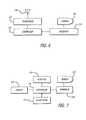
- FIG. 6is a functional block diagram of an illustrative embodiment of the present invention in accordance with the implementation depicted in FIGS. 2 and 3 .
- FIG. 7is a functional block diagram of an illustrative embodiment of the present invention in accordance with the implementation depicted in FIG. 4 .
- FIG. 8is a flow diagram of an illustrative embodiment of the present invention.
- present inventionis described herein in connection with a swimming application.
- present teachingsare also applicable to a variety of other applications including, by way of example, track and field events (running, walking, cycling, and etc.), rowing, skating, and motor sports such as automobile and motorcycle racing.
- present teachingsare not limited to sporting applications.
- the swimming pool exampleis of interest inasmuch as it involves environmental constraints introduced by water and the limitations these constraints place on an individual swimmer.
- the senses of vision and hearingare challenged more so than in air. Consequently, communication of information to the swimmer is more problematic than other applications. Breathing must be coordinated with the swimmer's stroke and this affects the body's natural breathing rhythms, which can result in blood-oxygen level maintenance issues. Also, electronic equipment and communications techniques are constrained when operated under water.
- FIG. 1illustrates an operational environment and an illustrative implementation of the teachings of the present invention in a swimming pool environment.
- An individual swimmer 6swims laps in water 10 above a swimming pool floor 8 . At the end of each lap, the swimmer 6 turns off the side wall 12 of the pool. The side wall terminates at the pool deck 14 .
- a transponder or transmitter(generally, a “communications device”) 4 is affixed to the swimmer 6 , which in the illustration is accomplished with a wristband housing the electronic circuitry.
- a communications linkis established between the transponder or transmitter 4 and a lap counter and timer 2 .
- the lap counter and timer 2includes a second communications device (not individually shown).
- the range of the communication linkis a matter of design choice.
- the rangeis selected so that as the swimmer swims laps, the transponder or transmitter moves into and out of range of the lap counter and timer device.
- the establishment of a communication link between the transponder or transmitterindicates that a lap of the circuit (i.e., the swimming pool) has been completed.
- the lap counter and timer deviceincludes a time reference that allows it to calculate the duration of each lap, as well as the duration, or elapsed time, since the start of the event.
- the lap counter and timing deviceis enabled to track the number of laps completed, the split time for each of a plurality of laps, as well as the elapsed time for the entire event.
- the lap counter and timer device 2rests on the bottom of the pool in a watertight housing. Battery power is preferred for operation of the device since it eliminates the requirement to connect to an external power supply.
- the lap counter and timer device 2has a display that faces upward and which employs large, readily visible characters. Light emitting diodes are preferred for this application as the bright illumination offers a high level of contrast, useful in the aquatic environment to facilitate viewing by the swimmer 6 .
- the physical location and arrangement of the lap counter and timer devicecombined with a readily visible display, enables the swimmer 6 to see the displayed lap count, split time, and elapsed time at the end of each lap.
- the wristband transponder or transmittercan be a passive or active device and is small and streamlined so as not to introduce adverse effects on the swimming activity.
- the lap counter and timer actuationcan be accomplished in several different modes.
- a temporal approachis employed.
- the time duration when the transponder or transmitter 4 is in close proximity to, and thus in communications range with, the lap counter and timer device 2is naturally brief as the swimmer 6 merely turns against the side wall 12 and proceeds to the next lap.
- the swimmer 6prior to beginning the event, and at the conclusion of the event, the swimmer 6 typically pauses at a stationary position near the side wall 12 of the pool.
- the lap counter and timer device 2is adapted to monitor this time period (the length of time the transponder or transmitter and lap counter and timer device are in communications range) and react to stop and reset the counter and timers operating therein.
- the timers and countersbegin normal operation when the swimmer 6 swims away from the lap counter and timer device 2 and thus moves out of communications range. A loss of the communications link initializes the device 2 to start counting and timing.
- an input devicecan be employed to allow the swimmer to manually stop, start, and reset the lap counter and timer device 2 .
- Such an input devicecan be a momentary contact switch accessible through a waterproof membrane on the device 2 , which is thus maintained in waterproof condition. Activation may be by foot or hand action of the swimmer.
- a magnetically coupled input devicesuch as a Hall effect sensor and handheld magnet can be used.
- a sonic device or a remote device using an electromagnetic, radio, infrared or light wavescan be used as will be appreciated by those of ordinary skill in the art.
- the signals communicatedinclude a unique transponder or transmitter identity signal.
- the informationis modulated onto the signal and is decoded by the lap counter and timer. It is subsequently compared to a stored value to determine if a match occurred.
- Thiseffectively discriminates each of the desired signals from any other non-desired signals that might be present.
- each event detected by the lap counter and timeris qualified as being linked to one or more particular transponder or transmitter identities.
- the teachingalso enable the device to track a plurality of uniquely identified transponders of transmitters simultaneously.
- the present inventionis readily capable of servicing plural users simultaneously.
- the lap counter and timer devicesoperate in conjunction with a transponder in a first embodiment and a transmitter in a second embodiment.
- a transponderis a device that is stimulated by an interrogation signal that is transmitted by the lap counter and timer device.
- the stimulation signalcauses the transponder to emit a responsive signal that is encoded with the aforementioned identification signal. While this approach increases the complexity of the lap counter and timer device, it is advantageous because the transponder can be implemented as a passive device that requires no independent electrical power source.
- Such systemsare understood by those possessing ordinary skill in the art and are currently implemented in card access systems used in building security, turnpike toll cards, and wave-by credit cards.
- the transmitter in the lap counter and timer devicerepetitively interrogates for a transponder within its communications range by repetitively transmitting an interrogation signal.
- an interrogation signalWhen no transponder is within communications range, there is no responsive identification signal received, and thus no swimmer present.
- the responsive identification signalis produced and received, and this the lap counter and timer device is enabled to determine the presence of the transponder.
- the second illustrative embodiment of the lap counter and timer deviceoperates in conjunction with a transmitter.
- the transmitteris an active device, requiring its own power source, which repetitively transmits an identification signal over a limited communications range.
- the lap counter and timer deviceimplements the corresponding receiver.
- the presence of the transmitter within the communications rangeis determined by the repetitive receipt of the identification signal.
- the frequency of the repetitive signalis a matter of design choice, and defines the minimum resolution in time of the various timing event contemplated herein. For amateur use, a repetition rate of ten per second is reasonable. For serious competitive events, a repetition rate of one hundred per second may be preferred.
- the communications link in any of the illustrative embodimentscan be established with any of a variety of communications technologies that are now understood, or later become available, to those skilled in the art.
- the choicesinclude, but are not limited to, visible light links, infrared light links, acoustic links, including ultra-sound, as well as various other frequencies of electromagnetic energy.
- a low frequency electromagnetic carrieris useful in an aquatic environment.
- FIG. 2is a diagram showing an operating environment for an illustrative embodiment of the present invention that employs a physiologic sensor.
- a physiologic sensorthat employs a light emitting diode and photodetector sensor and that are capable of monitoring heart rate and blood-oxygen levels.
- FIG. 2illustrates a swimmer 6 in water 10 with various structures described with like reference numerals as per FIG. 1 .
- FIG. 2illustrates the addition of a finger cot style physiologic sensor 5 that is coupled to the wristband style communications device 4 with a wire cable 7 .
- physiologic datais coupled to the wristband 4 where it is coupled with the aforementioned identification data and transmitted by the communications device to the display unit 2 on the pool floor.
- the display unit 2also displays the swimmer's heart rate and blood-oxygen levels each time the swimmer moves into the predetermined communication range of the unit 2 .
- the swimmer 6is able to look down to see the display unit 2 at the bottom of the pool. The swimmer is then informed as to the heart rate and blood oxygen levels, as well as the lap and time data, and can make adjustments to the level of effort as needed.
- FIG. 3is a diagram of a goggle display in accordance with an illustrative embodiment of the present invention.
- This embodimentis a refinement of the present invention where the person utilizing the system is continuously informed as data is gathered and updated by the system. This is made possible through implementation of a display unit that moves with the person traversing the circuit.
- the embodiment illustrated in FIG. 3is also directed to the swimming environment, but is applicable to many other applications as well.
- the display unitis a pair of swimmer's goggles 80 that incorporate a liquid crystal display 86 into one of the goggle 80 eyepieces 82 .
- the other eyepiece 84is of conventional design.
- the liquid crystal display 86is positioned outside the central field of view and is visible to the swimmer by slightly averting the angle of view toward the liquid crystal display 86 .
- a small lens group(not shown) is positioned between the liquid crystal display 86 and the eye so that the display is comfortably focused for viewing by the swimmer. Those skilled in the art are knowledgeable about such lens focusing groups.
- the gogglesare secured to the swimmer with an elastic strap 88 that couples the two eyepieces 84 and 82 about the swimmer's head.
- a thin wire cable 78couples the display 86 to the electronics that are disposed within the wristband 70 .
- Another thin wire cablecouples from the electronics in the wrist band 70 to the finger cot physiologic sensor 72 that is positioned on the swimmer's finger 76 (shown in phantom).
- the functions of the circuitry disposed within wristband 70will be more fully described hereinafter. It is noted that the lap events are detected through use of a transponder (not shown) disposed at the start/finish end of the circuit.
- a transceiver communications device(not shown in FIG.
- the wristband 70interrogates the transponder to determine when the swimmer has entered the predetermined communications range.
- the lap count split timesare updated and that information is written to the display 86 .
- the elapsed time, heart rate, and blood-oxygen levelsare continuously updated so that the information is available to the swimmer anytime it is desired.
- FIG. 4is a diagram of a goggle display in accordance with an illustrative embodiment of the present invention in which a separate transponder communications device is not required.
- the illustrative embodiment of FIG. 4comprises a pair of goggles 90 with a first eyepiece 92 and a second eyepiece 94 that are worn about the swimmer's head utilizing an elastic strap 95 .
- a liquid crystal display 96is disposed in eyepiece 94 such as that employed in the embodiment of FIG. 3 .
- the electronicsare alternatively located in a module 98 that is supported along the elastic head strap 95 . This approach obviates the need for a wrist strap as applied in the previous embodiments.
- a thin wire cableextends from the module 98 to the finger cot sensor 102 , which is disposed on the swimmer's finger 104 (shown in phantom).
- FIG. 4accomplishes this through the use of an actuator 106 disposed on the finger cot sensor 102 .
- the actuator 106is actuated each time the swimmer completes a lap, as well as at the beginning of the first lap. Actuation can be accomplished by pressing on the actuator 106 manually, or through impact with the pool side wall as the swimmer turns to change directions at the end of each lap.
- the actuator 106is electrically coupled to the circuitry in the module 98 and stimulates a controller (not shown) to increment the lap count and mark split time intervals.
- FIG. 5is a functional block diagram of an illustrative embodiment of the present invention.
- the embodiment depicted in FIG. 5is representative of the transponder embodiment, but differs only slightly (the addition of a transmitter 16 from the transceiver embodiment discussed respecting FIG. 1 .
- An antenna 24is employed since this embodiment utilizes an electromagnetic communications link.
- the antenna 24receives a transmit interrogation signal from an antenna driver circuit 18 , which sets the power and is thus the limiting factor with respect to the range of the device.
- the interrogation signalis generated by transmit circuit 16 , which is controlled by controller 16 .
- the repetition rateis programmed into the controller 26 .
- Controller 26may be any of the variety of processors, microprocessor, controllers, microcontrollers and other programmable devices as are understood by those having ordinary skill in the art.
- the interrogation signal output by the antenna 24is electromagnetically coupled to the transponder 34 , which emits a responsive identification signal comprising the transponder's 34 unique identity.
- the transmitterwould be illustrated by reference numeral 34 .
- the transmitterrepetitively emits a transmitter identification signal.
- the identification signalis received by antenna 24 and is coupled to antenna receiver 22 .
- the transmit and receive functionsdo not interfere with one another as they are multiplexed in time.
- the antenna receiver circuitdemodulates the signal and couples it to decode circuit 20 .
- Decode circuit 20determines the unique one, or plural, transponder (or transmitter) identity(ies).
- the decode circuit 20may alternatively be implemented in software in a controller 26 .
- the controller 26increments a lap count, measure and the time since the last lap count event, then calculates and displays on display 28 the lap count, split time, and elapsed time. It is to be understood that any limited subset of such information displayed is within the scope of the teachings herein.
- the aforementioned user inputsare entered through user inputs circuit 32 . As discussed herein before, this can include any of a variety of input devices.
- the information inputis similar to that information entered into prior art lap counters and timers, such as set and resent functions, display formats, and other information.
- the present inventionincorporates a countdown to start timer with corresponding display. This function allows the user to initialize a start sequence, such as by activating a user input, which is preceded by a countdown timer that gives the user time to get ready and set to begin the event. The duration of the count down timer is programmable by user selection.
- the controller 26gathers and stores lap-event data and marks it with respect to time by reference to an internal time reference in the device (not shown).
- the datais assembled into a database of information for use in the aforementioned calculations of laps, times and etc.
- the present inventionincludes a serial interface 30 coupled to the controller 26 , which is useful for transferring this database of information to another device.
- the usermay desire to save the database by transferring it through serial interface 30 to a separate computing device.
- the datacan then be further manipulated as desired by the user.
- Serial interface 30can employ any of the interface technologies understood by those skilled 110 in the art, including but not limited to RS-232 serial port specifications, USB serial interface specifications, IEEE 1394 port specifications, or a wireless interface standard or proprietary scheme. Optical and sonic coupling are applicable as well.
- FIG. 6is a functional block diagram of an illustrative embodiment of the present invention in accordance with the implementation depicted in FIGS. 2 and 3 .
- the communications device employedis a wireless transceiver 112 that is coupled to an antenna 118 .
- the transceivercommunicates with a fixed wireless communications device (not shown) located at the bottom of the swimming pool. See item 2 in FIG. 2 for reference.
- the wireless communication linkis designed for a predetermined communications range such that the two communications devices can communicate data only when they are within a predetermined distance of one another.
- a finger cot physiologic sensor 116is coupled to an interface circuit 114 that drives the sensor 116 and produces suitable data output to controller 110 . Sensors and interface circuits for detecting and coupling physiological data are known to those skilled in the art.
- the controller 110may be any of the variety of processor, controllers, or computers known to those skilled in the art to be suitable for dedicated control applications.
- interface 114couples this information to the controller 110 where it is temporarily stored.
- the physiologic datais transferred by wireless communications to the fixed unit, where it is displayed along with the lap and timing data. The communication occurs repetitively as plural laps are completed and at each lap the swimmer is able to view the updated displayed data.
- FIG. 7is a functional block diagram of an illustrative embodiment of the present invention in accordance with the implementation depicted in FIG. 4 .
- a finger cot physiologic sensor 130is coupled to an interface circuit 128 that outputs physiologic data to a controller 120 .
- Controller 120processes the physiologic data and writes it to display 122 .
- the display 122is a liquid crystal display located in eyewear worn by the swimmer.
- the display 122is a liquid crystal display located in eyewear worn by the swimmer.
- a runnermight prefer to have a wristband implementation of the system with a wristwatch like display.
- lap and timing informationis also written to the display 122 by the controller 120 .
- a clock-timer circuit 124is coupled to the controller 120 and provides a timing reference for lap and split time measurements.
- Clock-timer circuitsare known to those skilled in the art and may be external to or internal to the controller 120 .
- the illustrative embodiment in FIG. 7does not utilize a fixed communications device along the circuit. Rather, the user actuates an actuator 126 at the beginning of each lap. The actuation is coupled to controller 120 , which sets a time reference at each actuation. The controller 120 then measures the time since the previous actuation as a lap time (or split time) and also increments a lap counter variable. An elapsed time is also counted. The lap count, split time and elapsed times are output by the controller 120 to the display 122 for viewing by the swimmer.
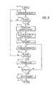
- FIG. 8is a flow diagram of an illustrative embodiment of the present invention.
- the process illustrated in FIG. 8relates to the transponder implementation of the present invention as described respecting FIG. 1 .
- the processis entered at step 40 and proceeds to step 42 where the lap counter and timer device interrogates and receives, looking for a transponder.
- step 44a test is conducted to determine if an identification signal has been received. If not, the interrogation step is repeated at step 42 and the cycle repeats until a signal is received at step 44 .
- the identification signalis decoded at step 46 to determine the transponder identity of the responsive transponder. Assuming there is a match in the identity, the receipt of the signal is marked with respect to time and accumulated in the lap data.
- the lap dataincludes the identity of the transponder and the time that such identity was realized, by coming into range of the lap counter and timer device.
- the lap countis incremented to indicate the total number of laps completed, the split time is calculated with respect to the lap data gathered from the previous lap event, and the elapsed time since the beginning of the event is updated. Also at step 48 , this information is displayed for the information of the user. Thus, as the event unfolds, the laps are individually tracked, the data stored, and the pertinent display information calculated and displayed.
- Steps 50 through 60 in FIG. 8implement the aforementioned temporal reset function of the present invention.
- the repetitive nature of the interrogation signalcauses the lap counter and timer device to repeat the test so long as the transponder is within range, and thereafter as well. Therefore, at step 50 , a counter is reset and the interrogation and receive operations are repeated at step 52 .
- the decode stepmay or may not be repeated, the decision to do so being a design choice.
- step 54is made at step 54 to determine if the identification has been received. If not, the process returns to step 42 to await the next lap event.
- step 54If the signal is received at step 54 , then the counter is incremented at step 56 .
- a testis conducted at step 58 to determine if the counter has reached a preset threshold. The threshold may be selected to specify a duration of time long enough to confidently indicated that the event is not a lap event and that the transponder (the swimmer) is resting at the starting position. If the counter has not reach the threshold, the process returns to step 52 to execute another interrogation cycle. On the other hand, at step 58 , if the counter threshold is met, then the lap counter is reset at step 60 so that another event can be initialized. Then, at step 62 , the process returns to a calling subroutine.
Landscapes
- Health & Medical Sciences (AREA)
- General Health & Medical Sciences (AREA)
- Physical Education & Sports Medicine (AREA)
- Engineering & Computer Science (AREA)
- Business, Economics & Management (AREA)
- Physics & Mathematics (AREA)
- Entrepreneurship & Innovation (AREA)
- Pulmonology (AREA)
- Educational Administration (AREA)
- Educational Technology (AREA)
- General Physics & Mathematics (AREA)
- Theoretical Computer Science (AREA)
- Measurement Of Unknown Time Intervals (AREA)
- Measuring And Recording Apparatus For Diagnosis (AREA)
Abstract
Description
- http://members.aol.com/herian/heusline.htm
- http://www.trovan.com/TRANSP-1. HTM
Claims (37)
Priority Applications (1)
| Application Number | Priority Date | Filing Date | Title |
|---|---|---|---|
| US10/116,183US6870466B2 (en) | 2002-04-03 | 2002-04-03 | Data display system and method for an object traversing a circuit |
Applications Claiming Priority (1)
| Application Number | Priority Date | Filing Date | Title |
|---|---|---|---|
| US10/116,183US6870466B2 (en) | 2002-04-03 | 2002-04-03 | Data display system and method for an object traversing a circuit |
Publications (2)
| Publication Number | Publication Date |
|---|---|
| US20030189484A1 US20030189484A1 (en) | 2003-10-09 |
| US6870466B2true US6870466B2 (en) | 2005-03-22 |
Family
ID=28673911
Family Applications (1)
| Application Number | Title | Priority Date | Filing Date |
|---|---|---|---|
| US10/116,183Expired - Fee RelatedUS6870466B2 (en) | 2002-04-03 | 2002-04-03 | Data display system and method for an object traversing a circuit |
Country Status (1)
| Country | Link |
|---|---|
| US (1) | US6870466B2 (en) |
Cited By (24)
| Publication number | Priority date | Publication date | Assignee | Title |
|---|---|---|---|---|
| US20030235116A1 (en)* | 2002-06-20 | 2003-12-25 | Astra Gesellschaft Fur Asset Management Mbh & Co. Kg | Method and device for automatic timing in mass sporting events |
| US20050225868A1 (en)* | 2004-04-13 | 2005-10-13 | Nelson Andrew J | System and method for displaying information on athletic eyewear |
| US20050225867A1 (en)* | 2001-12-05 | 2005-10-13 | Yamamoto Kogaku Co., Ltd. | Sports goggle |
| US20050243651A1 (en)* | 2004-04-30 | 2005-11-03 | Brad Balley | Swim lap counter/timer |
| US20090073330A1 (en)* | 1999-12-01 | 2009-03-19 | Roar Viala | Head mountable display system |
| US20090112630A1 (en)* | 2007-10-26 | 2009-04-30 | Collins Jr Williams F | System and method for collection and communication of data from multiple patient care devices |
| US20100134297A1 (en)* | 2008-12-03 | 2010-06-03 | Curtis Baldwin | Activity monitoring eyewear |
| US20100159827A1 (en)* | 2005-06-15 | 2010-06-24 | Mark Rhodes | Underwater remote sensing |
| US20100304934A1 (en)* | 2009-06-02 | 2010-12-02 | Swimnetix Corporation | Aquatic training system and method |
| US20110149694A1 (en)* | 2009-12-21 | 2011-06-23 | Masami Sakita | Swim timer, lap cunter and swim analyzer |
| US8026821B2 (en) | 2000-05-05 | 2011-09-27 | Hill-Rom Services, Inc. | System for monitoring caregivers and equipment at a patient location |
| US20110280107A1 (en)* | 2009-11-19 | 2011-11-17 | Lawrence James Day | Submersible chronograph and counter |
| US8421606B2 (en) | 2004-08-02 | 2013-04-16 | Hill-Rom Services, Inc. | Wireless bed locating system |
| US20150209614A1 (en)* | 2014-01-28 | 2015-07-30 | Samsung Electronics Co., Ltd. | Swimming race system, swimming race method, method of managing water quality, and display apparatus |
| US9142923B2 (en) | 2003-08-21 | 2015-09-22 | Hill-Rom Services, Inc. | Hospital bed having wireless data and locating capability |
| US9217634B1 (en) | 2015-05-06 | 2015-12-22 | Swimpad Corporation | Swim lap counting and timing system and methods for event detection from noisy source data |
| US9230421B2 (en) | 2000-05-05 | 2016-01-05 | Hill-Rom Services, Inc. | System for monitoring caregivers and equipment |
| US10022087B2 (en) | 2012-11-29 | 2018-07-17 | Johnson Outdoors Inc. | Swim stroke counter |
| US10360787B2 (en) | 2016-05-05 | 2019-07-23 | Hill-Rom Services, Inc. | Discriminating patient care communications system |
| US10816653B2 (en) | 2015-11-25 | 2020-10-27 | Swimmetric, LLC | Swimming speedometer system with near-eye display |
| US11213722B2 (en) | 2015-11-25 | 2022-01-04 | Swimmetric, LLC | Swimming speedometer system with near-eye display |
| US12186241B2 (en) | 2021-01-22 | 2025-01-07 | Hill-Rom Services, Inc. | Time-based wireless pairing between a medical device and a wall unit |
| US12263376B1 (en)* | 2021-11-17 | 2025-04-01 | Corporation For National Research Initiatives | Microsensors applied to athletes bodies in order to provide real-time feedback about sport-specific technique for sport performance improvements |
| US12279999B2 (en) | 2021-01-22 | 2025-04-22 | Hill-Rom Services, Inc. | Wireless configuration and authorization of a wall unit that pairs with a medical device |
Families Citing this family (42)
| Publication number | Priority date | Publication date | Assignee | Title |
|---|---|---|---|---|
| US7605685B2 (en)* | 2006-01-27 | 2009-10-20 | Orbiter, Llc | Portable lap counter and system |
| US20070260478A1 (en)* | 2006-05-02 | 2007-11-08 | International Business Machines Corporation | Delivery of Health Insurance Plan Options |
| US7853446B2 (en)* | 2006-05-02 | 2010-12-14 | International Business Machines Corporation | Generation of codified electronic medical records by processing clinician commentary |
| DE102007001820B3 (en)* | 2006-10-12 | 2008-01-24 | Cairos Technologies Ag | System for detecting contact of player with ball comprises magnetic field generator on player generating field with characteristic code sequence or frequency, sensor on ball detecting field and identifying player |
| NL2001465C2 (en)* | 2008-04-10 | 2009-10-13 | Riny Bay Sportswear | Counting and indication device and use thereof. |
| GB2461946A (en)* | 2008-07-22 | 2010-01-27 | Karen Bhopal | Swimming distance counter |
| US9216341B2 (en)* | 2008-08-04 | 2015-12-22 | Xipu Li | Real-time swimming monitor |
| US20110076951A1 (en)* | 2009-09-30 | 2011-03-31 | Kabushiki Kaisha Toshiba | Information processing apparatus |
| US9375627B2 (en) | 2011-01-20 | 2016-06-28 | Innovative Timing Systems, Llc | Laser detection enhanced RFID tag reading event timing system and method |
| WO2012100237A2 (en) | 2011-01-20 | 2012-07-26 | Innovative Timing Systems, Llc | Rfid timing system and method with integrated event participant location tracking |
| US9002979B2 (en) | 2010-01-11 | 2015-04-07 | Innovative Timing Systems, Llc | Sports timing system (STS) event and participant announcement communication system (EPACS) and method |
| US9076278B2 (en) | 2010-07-29 | 2015-07-07 | Innovative Timing Systems, Llc | Automated timing systems and methods having multiple time event recorders and an integrated user time entry interface |
| US9495568B2 (en) | 2010-01-11 | 2016-11-15 | Innovative Timing Systems, Llc | Integrated timing system and method having a highly portable RFID tag reader with GPS location determination |
| US8576051B2 (en) | 2010-01-29 | 2013-11-05 | Innovative Timing Systems, LLC. | Spaced apart extended range RFID tag assemblies and methods of operation |
| US8576050B2 (en) | 2010-01-29 | 2013-11-05 | Innovative Timing Systems, LLC. | Extended range RFID tag assemblies and methods of operation |
| US8360331B2 (en)* | 2010-01-29 | 2013-01-29 | Innovative Timing Systems, Llc | Harsh operating environment RFID tag assemblies and methods of manufacturing thereof |
| US9883332B2 (en) | 2010-03-01 | 2018-01-30 | Innovative Timing Systems, Llc | System and method of an event timing system having integrated geodetic timing points |
| EP2543002A4 (en) | 2010-03-01 | 2016-12-28 | Innovative Timing Systems Llc | Variably spaced multi-point rfid tag reader systems and methods |
| WO2012031303A2 (en) | 2010-09-03 | 2012-03-08 | Innovative Timing Systems, Llc | Integrated detection point passive rfid tag reader and event timing system and method |
| CN103124542B (en)* | 2010-10-08 | 2015-11-25 | 皇家飞利浦电子股份有限公司 | For providing protective eye lens, the system and method for feedback |
| US9508036B2 (en) | 2011-01-20 | 2016-11-29 | Innovative Timing Systems, Llc | Helmet mountable timed event RFID tag assembly and method of use |
| USD676790S1 (en) | 2012-01-20 | 2013-02-26 | Innovative Timing Systems, LLC. | RFID tag mount assembly for a bicycle |
| US9942455B2 (en) | 2012-01-25 | 2018-04-10 | Innovative Timing Systems, Llc | Timing system and method with integrated participant event image capture management services |
| US10430404B2 (en)* | 2012-05-22 | 2019-10-01 | Nitin Gambhir | System and method for tracking events |
| US9187154B2 (en)* | 2012-08-01 | 2015-11-17 | Innovative Timing Systems, Llc | RFID tag reading systems and methods for aquatic timed events |
| US9192817B2 (en)* | 2012-12-17 | 2015-11-24 | Anthony Frolov | Device for training swimmers and performing physiotherapeutic exercises |
| ITRM20130096A1 (en)* | 2013-02-19 | 2014-08-20 | Safety Bed S R L | "AUTOMATIC SYSTEM WITH HIGH PRECISION AND RELIABILITY FOR CHRONOMETRIC MONITORING AND REAL-TIME ANALYSIS OF A PLURALITY OF DATA RELATING TO THE SINGLE PERFORMANCE OF SWIMMING ATHLETES" |
| US20160022144A1 (en)* | 2013-03-15 | 2016-01-28 | Innovative Timing Systems Llc | System and method of integrating participant biometrics within an event timing system |
| GB2513357A (en)* | 2013-04-24 | 2014-10-29 | Kevin Warren | Apparatus for detecting laps made by a swimmer |
| US11039284B1 (en)* | 2015-03-03 | 2021-06-15 | Amtech Systems, LLC | Vehicle tracking system using smart-phone as active transponder |
| US20170178524A1 (en)* | 2015-05-06 | 2017-06-22 | Ocula Corporation | Swim Lap Counting and Timing System and Methods for Event Detection from Noisy Source Data |
| WO2016196217A1 (en)* | 2015-05-29 | 2016-12-08 | Nike Innovate C.V. | Enhancing exercise through augmented reality |
| GB2545191A (en)* | 2015-12-08 | 2017-06-14 | 222 Sports Ltd | Swimming performance tracking device |
| US10818152B2 (en)* | 2018-01-15 | 2020-10-27 | Universal City Studios Llc | Interactive systems and methods with feedback devices |
| FR3077454B1 (en)* | 2018-01-29 | 2020-05-22 | Alexandre Henic | METHOD, DEVICE AND USE THEREOF, SYSTEM AND COMPUTER PROGRAM PRODUCT FOR COUNTING THE NUMBER OF LENGTHS PERFORMED BY A SWIMMER |
| US10488667B1 (en)* | 2018-05-21 | 2019-11-26 | Flipper, Inc. | Systems and methods for minimally intrusive displays |
| US11612362B2 (en) | 2019-02-12 | 2023-03-28 | Flipper, Inc. | Systems and methods for minimally intrusive displays with heart rate monitoring and workouts |
| US11766185B2 (en) | 2019-02-12 | 2023-09-26 | Flipper Inc. | Systems and methods for minimally intrusive displays with heart rate monitoring and workouts |
| US11836569B1 (en) | 2019-12-06 | 2023-12-05 | Amtech Systems, LLC | Vehicle tracking system using smart-phone as active transponder |
| US11839803B2 (en) | 2020-08-04 | 2023-12-12 | Orbiter, Inc. | System and process for RFID tag and reader detection in a racing environment |
| US20240233508A1 (en)* | 2023-01-05 | 2024-07-11 | Vivek Sandrapaty | Drowing prevention system |
| KR102746596B1 (en)* | 2024-05-30 | 2024-12-24 | 사단법인 동의과학대스포츠클럽 | Smart safety management system of swimming exercise |
Citations (13)
| Publication number | Priority date | Publication date | Assignee | Title |
|---|---|---|---|---|
| US4823367A (en)* | 1987-08-07 | 1989-04-18 | Rikagaku Kenkyujyo and Hochiki Corp. | Method and apparatus for automatic lap counting |
| US5125010A (en)* | 1990-10-15 | 1992-06-23 | Lee Lewis C | Lap counting system |
| US5136621A (en)* | 1990-12-11 | 1992-08-04 | Mitchell David E | Timing and lap counting device for a swimmer |
| US5557085A (en) | 1992-01-20 | 1996-09-17 | Rso Corporation N.V. | Method and device for electronic identification |
| US5585871A (en)* | 1995-05-26 | 1996-12-17 | Linden; Harry | Multi-function display apparatus |
| US5685722A (en)* | 1995-04-13 | 1997-11-11 | U.S. Divers Co., Inc. | Electronic timing swimmer's goggles |
| US5751223A (en) | 1995-03-22 | 1998-05-12 | International Computers Limited | Electronic identification system |
| US5812049A (en)* | 1996-10-25 | 1998-09-22 | Micro Utility Ltd. | System and method for monitoring a competitive activity |
| US6130859A (en) | 1997-12-01 | 2000-10-10 | Divecom Ltd. | Method and apparatus for carrying out high data rate and voice underwater communication |
| US6144620A (en)* | 1997-08-19 | 2000-11-07 | Depoortere; Thomas | Apparatus for monitoring an athletic activity |
| US6144301A (en) | 1997-02-10 | 2000-11-07 | Safetrac Control Systems, Inc. | Electronic tracking tag |
| US6222452B1 (en) | 1996-12-16 | 2001-04-24 | Confidence International Ab | Electronic identification tag |
| US6714133B2 (en)* | 1999-12-15 | 2004-03-30 | Koninklijke Philips Electronics N.V. | Short range communication system |
Family Cites Families (2)
| Publication number | Priority date | Publication date | Assignee | Title |
|---|---|---|---|---|
| EP1210345B1 (en)* | 1999-09-08 | 2004-03-03 | Glaxo Group Limited | Oxazole ppar antagonists |
| US6414002B1 (en)* | 1999-09-22 | 2002-07-02 | Bristol-Myers Squibb Company | Substituted acid derivatives useful as antidiabetic and antiobesity agents and method |
- 2002
- 2002-04-03USUS10/116,183patent/US6870466B2/ennot_activeExpired - Fee Related
Patent Citations (13)
| Publication number | Priority date | Publication date | Assignee | Title |
|---|---|---|---|---|
| US4823367A (en)* | 1987-08-07 | 1989-04-18 | Rikagaku Kenkyujyo and Hochiki Corp. | Method and apparatus for automatic lap counting |
| US5125010A (en)* | 1990-10-15 | 1992-06-23 | Lee Lewis C | Lap counting system |
| US5136621A (en)* | 1990-12-11 | 1992-08-04 | Mitchell David E | Timing and lap counting device for a swimmer |
| US5557085A (en) | 1992-01-20 | 1996-09-17 | Rso Corporation N.V. | Method and device for electronic identification |
| US5751223A (en) | 1995-03-22 | 1998-05-12 | International Computers Limited | Electronic identification system |
| US5685722A (en)* | 1995-04-13 | 1997-11-11 | U.S. Divers Co., Inc. | Electronic timing swimmer's goggles |
| US5585871A (en)* | 1995-05-26 | 1996-12-17 | Linden; Harry | Multi-function display apparatus |
| US5812049A (en)* | 1996-10-25 | 1998-09-22 | Micro Utility Ltd. | System and method for monitoring a competitive activity |
| US6222452B1 (en) | 1996-12-16 | 2001-04-24 | Confidence International Ab | Electronic identification tag |
| US6144301A (en) | 1997-02-10 | 2000-11-07 | Safetrac Control Systems, Inc. | Electronic tracking tag |
| US6144620A (en)* | 1997-08-19 | 2000-11-07 | Depoortere; Thomas | Apparatus for monitoring an athletic activity |
| US6130859A (en) | 1997-12-01 | 2000-10-10 | Divecom Ltd. | Method and apparatus for carrying out high data rate and voice underwater communication |
| US6714133B2 (en)* | 1999-12-15 | 2004-03-30 | Koninklijke Philips Electronics N.V. | Short range communication system |
Cited By (45)
| Publication number | Priority date | Publication date | Assignee | Title |
|---|---|---|---|---|
| US20090073330A1 (en)* | 1999-12-01 | 2009-03-19 | Roar Viala | Head mountable display system |
| US9666061B2 (en) | 2000-05-05 | 2017-05-30 | Hill-Rom Services, Inc. | System for monitoring caregivers and equipment |
| US8487774B2 (en) | 2000-05-05 | 2013-07-16 | Hill-Rom Services, Inc. | System for monitoring caregivers and equipment |
| US8766804B2 (en) | 2000-05-05 | 2014-07-01 | Hill-Rom Services, Inc. | System for monitoring caregivers and equipment |
| US8258965B2 (en) | 2000-05-05 | 2012-09-04 | Hill-Rom Services, Inc. | System for monitoring caregivers and equipment at a patient location |
| US9230421B2 (en) | 2000-05-05 | 2016-01-05 | Hill-Rom Services, Inc. | System for monitoring caregivers and equipment |
| US8026821B2 (en) | 2000-05-05 | 2011-09-27 | Hill-Rom Services, Inc. | System for monitoring caregivers and equipment at a patient location |
| US20050225867A1 (en)* | 2001-12-05 | 2005-10-13 | Yamamoto Kogaku Co., Ltd. | Sports goggle |
| US7192137B2 (en)* | 2001-12-05 | 2007-03-20 | Yamamoto Kogaku Co., Ltd. | Sports goggle |
| US7057975B2 (en)* | 2002-06-20 | 2006-06-06 | ASTRA Gesellschaft für Asset Management mbH & Co. KG | Method and device for automatic timing in mass sporting events |
| US20030235116A1 (en)* | 2002-06-20 | 2003-12-25 | Astra Gesellschaft Fur Asset Management Mbh & Co. Kg | Method and device for automatic timing in mass sporting events |
| US9925104B2 (en) | 2003-08-21 | 2018-03-27 | Hill-Rom Services, Inc. | Hospital bed and room communication modules |
| US10206837B2 (en) | 2003-08-21 | 2019-02-19 | Hill-Rom Services, Inc. | Hospital bed and room communication modules |
| US9572737B2 (en) | 2003-08-21 | 2017-02-21 | Hill-Rom Services, Inc. | Hospital bed having communication modules |
| US9142923B2 (en) | 2003-08-21 | 2015-09-22 | Hill-Rom Services, Inc. | Hospital bed having wireless data and locating capability |
| US7185983B2 (en)* | 2004-04-13 | 2007-03-06 | Andrew Nelson | System and method for displaying information on athletic eyewear |
| US20050225868A1 (en)* | 2004-04-13 | 2005-10-13 | Nelson Andrew J | System and method for displaying information on athletic eyewear |
| US7029170B2 (en)* | 2004-04-30 | 2006-04-18 | Brad Bailey | Swim lap counter/timer |
| US20050243651A1 (en)* | 2004-04-30 | 2005-11-03 | Brad Balley | Swim lap counter/timer |
| US8421606B2 (en) | 2004-08-02 | 2013-04-16 | Hill-Rom Services, Inc. | Wireless bed locating system |
| US20100159827A1 (en)* | 2005-06-15 | 2010-06-24 | Mark Rhodes | Underwater remote sensing |
| US8756078B2 (en) | 2007-10-26 | 2014-06-17 | Hill-Rom Services, Inc. | System and method for collection and communication of data from multiple patient care devices |
| US11031130B2 (en) | 2007-10-26 | 2021-06-08 | Hill-Rom Services, Inc. | Patient support apparatus having data collection and communication capability |
| US8082160B2 (en) | 2007-10-26 | 2011-12-20 | Hill-Rom Services, Inc. | System and method for collection and communication of data from multiple patient care devices |
| US20090112630A1 (en)* | 2007-10-26 | 2009-04-30 | Collins Jr Williams F | System and method for collection and communication of data from multiple patient care devices |
| US9734293B2 (en) | 2007-10-26 | 2017-08-15 | Hill-Rom Services, Inc. | System and method for association of patient care devices to a patient |
| US20100134297A1 (en)* | 2008-12-03 | 2010-06-03 | Curtis Baldwin | Activity monitoring eyewear |
| US20100304934A1 (en)* | 2009-06-02 | 2010-12-02 | Swimnetix Corporation | Aquatic training system and method |
| US8317659B2 (en)* | 2009-06-02 | 2012-11-27 | Swimnetix Corporation | Aquatic training system and method |
| US8472285B2 (en)* | 2009-11-19 | 2013-06-25 | Lawrence James Day | Submersible chronograph and counter |
| US20110280107A1 (en)* | 2009-11-19 | 2011-11-17 | Lawrence James Day | Submersible chronograph and counter |
| US20110149694A1 (en)* | 2009-12-21 | 2011-06-23 | Masami Sakita | Swim timer, lap cunter and swim analyzer |
| US8406085B2 (en)* | 2009-12-21 | 2013-03-26 | Masami Sakita | Swim device |
| US10022087B2 (en) | 2012-11-29 | 2018-07-17 | Johnson Outdoors Inc. | Swim stroke counter |
| US9539469B2 (en)* | 2014-01-28 | 2017-01-10 | Samsung Electronics Co., Ltd. | Swimming race system, swimming race method, method of managing water quality, and display apparatus |
| US20150209614A1 (en)* | 2014-01-28 | 2015-07-30 | Samsung Electronics Co., Ltd. | Swimming race system, swimming race method, method of managing water quality, and display apparatus |
| US9217634B1 (en) | 2015-05-06 | 2015-12-22 | Swimpad Corporation | Swim lap counting and timing system and methods for event detection from noisy source data |
| US9778622B2 (en) | 2015-05-06 | 2017-10-03 | Ocula Corporation | Swim lap counting and timing system and methods for event detection from noisy source data |
| US10816653B2 (en) | 2015-11-25 | 2020-10-27 | Swimmetric, LLC | Swimming speedometer system with near-eye display |
| US11213722B2 (en) | 2015-11-25 | 2022-01-04 | Swimmetric, LLC | Swimming speedometer system with near-eye display |
| US10360787B2 (en) | 2016-05-05 | 2019-07-23 | Hill-Rom Services, Inc. | Discriminating patient care communications system |
| US11791055B2 (en) | 2016-05-05 | 2023-10-17 | Hill-Rom Services, Inc. | Discriminating patient care communications system |
| US12186241B2 (en) | 2021-01-22 | 2025-01-07 | Hill-Rom Services, Inc. | Time-based wireless pairing between a medical device and a wall unit |
| US12279999B2 (en) | 2021-01-22 | 2025-04-22 | Hill-Rom Services, Inc. | Wireless configuration and authorization of a wall unit that pairs with a medical device |
| US12263376B1 (en)* | 2021-11-17 | 2025-04-01 | Corporation For National Research Initiatives | Microsensors applied to athletes bodies in order to provide real-time feedback about sport-specific technique for sport performance improvements |
Also Published As
| Publication number | Publication date |
|---|---|
| US20030189484A1 (en) | 2003-10-09 |
Similar Documents
| Publication | Publication Date | Title |
|---|---|---|
| US6870466B2 (en) | Data display system and method for an object traversing a circuit | |
| US4823367A (en) | Method and apparatus for automatic lap counting | |
| CN108742559B (en) | Wearable heart rate monitor | |
| US5812049A (en) | System and method for monitoring a competitive activity | |
| US20020013535A1 (en) | Electronic wrist-worn device and method of controlling the same | |
| CN105433949B (en) | Hybrid angular motion sensor | |
| CN104287703B (en) | Use of Gyroscopes in Personal Fitness Tracking Devices | |
| JP5933465B2 (en) | Personal exercise equipment triggered by RFID | |
| CN106333667B (en) | Wearable heart rate monitor | |
| EP3383510B1 (en) | Activity identification and tracking | |
| US5136621A (en) | Timing and lap counting device for a swimmer | |
| CN108903920A (en) | Portable biometric metering monitor and its operating method | |
| US20140018686A1 (en) | Data collection unit power and noise management | |
| JP5736321B2 (en) | Exercise system and communication method | |
| US20180204474A1 (en) | Swim Lap Counting and Timing System and Methods for Event Detection from Noisy Source Data | |
| US20130332286A1 (en) | Activity type detection and targeted advertising system | |
| CN102835951A (en) | Mobile wrist strap equipment and working method thereof | |
| AU2013296579A1 (en) | Athletic monitoring | |
| JPH11505458A (en) | Programmable audible pacing device | |
| US5130955A (en) | Athletic timer correction system | |
| AU2016219557B2 (en) | Devices and methods for sports and/or aquatic environments | |
| CA2984000A1 (en) | Swim lap counting and timing system and methods for event detection from noisy source data | |
| US20180001182A1 (en) | Patent Application for Athletic Training Device | |
| GB2282521A (en) | Sport shoes | |
| GB2545191A (en) | Swimming performance tracking device |
Legal Events
| Date | Code | Title | Description |
|---|---|---|---|
| AS | Assignment | Owner name:HEWLETT-PACKARD COMPANY, COLORADO Free format text:ASSIGNMENT OF ASSIGNORS INTEREST;ASSIGNORS:RUST, ROBERT A.;OLDFIELD, BARRY J.;REEL/FRAME:013030/0562 Effective date:20020328 | |
| AS | Assignment | Owner name:HEWLETT-PACKARD DEVELOPMENT COMPANY, L.P., COLORADO Free format text:ASSIGNMENT OF ASSIGNORS INTEREST;ASSIGNOR:HEWLETT-PACKARD COMPANY;REEL/FRAME:013776/0928 Effective date:20030131 Owner name:HEWLETT-PACKARD DEVELOPMENT COMPANY, L.P., COLORAD Free format text:ASSIGNMENT OF ASSIGNORS INTEREST;ASSIGNOR:HEWLETT-PACKARD COMPANY;REEL/FRAME:013776/0928 Effective date:20030131 Owner name:HEWLETT-PACKARD DEVELOPMENT COMPANY, L.P.,COLORADO Free format text:ASSIGNMENT OF ASSIGNORS INTEREST;ASSIGNOR:HEWLETT-PACKARD COMPANY;REEL/FRAME:013776/0928 Effective date:20030131 | |
| FPAY | Fee payment | Year of fee payment:4 | |
| FPAY | Fee payment | Year of fee payment:8 | |
| AS | Assignment | Owner name:HEWLETT PACKARD ENTERPRISE DEVELOPMENT LP, TEXAS Free format text:ASSIGNMENT OF ASSIGNORS INTEREST;ASSIGNOR:HEWLETT-PACKARD DEVELOPMENT COMPANY, L.P.;REEL/FRAME:037079/0001 Effective date:20151027 | |
| REMI | Maintenance fee reminder mailed | ||
| LAPS | Lapse for failure to pay maintenance fees | ||
| STCH | Information on status: patent discontinuation | Free format text:PATENT EXPIRED DUE TO NONPAYMENT OF MAINTENANCE FEES UNDER 37 CFR 1.362 | |
| FP | Lapsed due to failure to pay maintenance fee | Effective date:20170322 |