US6869528B2 - Filtering system for runoff water - Google Patents
Filtering system for runoff waterDownload PDFInfo
- Publication number
- US6869528B2 US6869528B2US10/040,611US4061102AUS6869528B2US 6869528 B2US6869528 B2US 6869528B2US 4061102 AUS4061102 AUS 4061102AUS 6869528 B2US6869528 B2US 6869528B2
- Authority
- US
- United States
- Prior art keywords
- fluid
- filtering
- layer
- drain
- reservoir
- Prior art date
- Legal status (The legal status is an assumption and is not a legal conclusion. Google has not performed a legal analysis and makes no representation as to the accuracy of the status listed.)
- Expired - Lifetime
Links
- XLYOFNOQVPJJNP-UHFFFAOYSA-NwaterSubstancesOXLYOFNOQVPJJNP-UHFFFAOYSA-N0.000titleclaimsabstractdescription136
- 238000001914filtrationMethods0.000titleclaimsabstractdescription118
- 230000004888barrier functionEffects0.000claimsabstractdescription58
- 239000007788liquidSubstances0.000claimsabstractdescription14
- 239000012530fluidSubstances0.000claimsdescription102
- 239000000463materialSubstances0.000claimsdescription55
- 230000005484gravityEffects0.000claimsdescription6
- 239000004746geotextileSubstances0.000claimsdescription5
- 238000007599dischargingMethods0.000claims3
- 239000011148porous materialSubstances0.000claims1
- 239000000839emulsionSubstances0.000abstractdescription4
- 230000007246mechanismEffects0.000description22
- 239000003921oilSubstances0.000description19
- 229920006395saturated elastomerPolymers0.000description6
- 238000000034methodMethods0.000description4
- 239000003344environmental pollutantSubstances0.000description3
- 239000002245particleSubstances0.000description3
- 231100000719pollutantToxicity0.000description3
- 230000008569processEffects0.000description3
- 238000000926separation methodMethods0.000description2
- 125000006850spacer groupChemical group0.000description2
- 230000008901benefitEffects0.000description1
- 239000000356contaminantSubstances0.000description1
- 239000003657drainage waterSubstances0.000description1
- 230000003203everyday effectEffects0.000description1
- 230000035699permeabilityEffects0.000description1
- 239000002699waste materialSubstances0.000description1
Images


Classifications
- E—FIXED CONSTRUCTIONS
- E03—WATER SUPPLY; SEWERAGE
- E03F—SEWERS; CESSPOOLS
- E03F5/00—Sewerage structures
- E03F5/14—Devices for separating liquid or solid substances from sewage, e.g. sand or sludge traps, rakes or grates
- E03F5/16—Devices for separating oil, water or grease from sewage in drains leading to the main sewer
- B—PERFORMING OPERATIONS; TRANSPORTING
- B01—PHYSICAL OR CHEMICAL PROCESSES OR APPARATUS IN GENERAL
- B01D—SEPARATION
- B01D17/00—Separation of liquids, not provided for elsewhere, e.g. by thermal diffusion
- B01D17/02—Separation of non-miscible liquids
- B01D17/0208—Separation of non-miscible liquids by sedimentation
- B—PERFORMING OPERATIONS; TRANSPORTING
- B01—PHYSICAL OR CHEMICAL PROCESSES OR APPARATUS IN GENERAL
- B01D—SEPARATION
- B01D17/00—Separation of liquids, not provided for elsewhere, e.g. by thermal diffusion
- B01D17/02—Separation of non-miscible liquids
- B01D17/04—Breaking emulsions
- B01D17/045—Breaking emulsions with coalescers
- B—PERFORMING OPERATIONS; TRANSPORTING
- B01—PHYSICAL OR CHEMICAL PROCESSES OR APPARATUS IN GENERAL
- B01D—SEPARATION
- B01D17/00—Separation of liquids, not provided for elsewhere, e.g. by thermal diffusion
- B01D17/08—Thickening liquid suspensions by filtration
- B—PERFORMING OPERATIONS; TRANSPORTING
- B01—PHYSICAL OR CHEMICAL PROCESSES OR APPARATUS IN GENERAL
- B01D—SEPARATION
- B01D17/00—Separation of liquids, not provided for elsewhere, e.g. by thermal diffusion
- B01D17/08—Thickening liquid suspensions by filtration
- B01D17/10—Thickening liquid suspensions by filtration with stationary filtering elements
- B—PERFORMING OPERATIONS; TRANSPORTING
- B01—PHYSICAL OR CHEMICAL PROCESSES OR APPARATUS IN GENERAL
- B01D—SEPARATION
- B01D24/00—Filters comprising loose filtering material, i.e. filtering material without any binder between the individual particles or fibres thereof
- B01D24/002—Filters comprising loose filtering material, i.e. filtering material without any binder between the individual particles or fibres thereof with multiple filtering elements in parallel connection
- B01D24/005—Filters being divided into a plurality of cells or compartments
- B—PERFORMING OPERATIONS; TRANSPORTING
- B01—PHYSICAL OR CHEMICAL PROCESSES OR APPARATUS IN GENERAL
- B01D—SEPARATION
- B01D24/00—Filters comprising loose filtering material, i.e. filtering material without any binder between the individual particles or fibres thereof
- B01D24/007—Filters comprising loose filtering material, i.e. filtering material without any binder between the individual particles or fibres thereof with multiple filtering elements in series connection
- B01D24/008—Filters comprising loose filtering material, i.e. filtering material without any binder between the individual particles or fibres thereof with multiple filtering elements in series connection arranged concentrically or coaxially
- B—PERFORMING OPERATIONS; TRANSPORTING
- B01—PHYSICAL OR CHEMICAL PROCESSES OR APPARATUS IN GENERAL
- B01D—SEPARATION
- B01D24/00—Filters comprising loose filtering material, i.e. filtering material without any binder between the individual particles or fibres thereof
- B01D24/02—Filters comprising loose filtering material, i.e. filtering material without any binder between the individual particles or fibres thereof with the filter bed stationary during the filtration
- B01D24/04—Filters comprising loose filtering material, i.e. filtering material without any binder between the individual particles or fibres thereof with the filter bed stationary during the filtration the filtering material being clamped between pervious fixed walls
- B01D24/042—Filters comprising loose filtering material, i.e. filtering material without any binder between the individual particles or fibres thereof with the filter bed stationary during the filtration the filtering material being clamped between pervious fixed walls the filtering material being held in a flexible porous bag
- B—PERFORMING OPERATIONS; TRANSPORTING
- B01—PHYSICAL OR CHEMICAL PROCESSES OR APPARATUS IN GENERAL
- B01D—SEPARATION
- B01D24/00—Filters comprising loose filtering material, i.e. filtering material without any binder between the individual particles or fibres thereof
- B01D24/02—Filters comprising loose filtering material, i.e. filtering material without any binder between the individual particles or fibres thereof with the filter bed stationary during the filtration
- B01D24/04—Filters comprising loose filtering material, i.e. filtering material without any binder between the individual particles or fibres thereof with the filter bed stationary during the filtration the filtering material being clamped between pervious fixed walls
- B01D24/08—Filters comprising loose filtering material, i.e. filtering material without any binder between the individual particles or fibres thereof with the filter bed stationary during the filtration the filtering material being clamped between pervious fixed walls the filtering material being supported by at least two pervious coaxial walls
- B—PERFORMING OPERATIONS; TRANSPORTING
- B01—PHYSICAL OR CHEMICAL PROCESSES OR APPARATUS IN GENERAL
- B01D—SEPARATION
- B01D24/00—Filters comprising loose filtering material, i.e. filtering material without any binder between the individual particles or fibres thereof
- B01D24/02—Filters comprising loose filtering material, i.e. filtering material without any binder between the individual particles or fibres thereof with the filter bed stationary during the filtration
- B01D24/20—Filters comprising loose filtering material, i.e. filtering material without any binder between the individual particles or fibres thereof with the filter bed stationary during the filtration the filtering material being provided in an open container
- B01D24/22—Downward filtration, the filter material being supported by pervious surfaces
- B—PERFORMING OPERATIONS; TRANSPORTING
- B01—PHYSICAL OR CHEMICAL PROCESSES OR APPARATUS IN GENERAL
- B01D—SEPARATION
- B01D24/00—Filters comprising loose filtering material, i.e. filtering material without any binder between the individual particles or fibres thereof
- B01D24/02—Filters comprising loose filtering material, i.e. filtering material without any binder between the individual particles or fibres thereof with the filter bed stationary during the filtration
- B01D24/20—Filters comprising loose filtering material, i.e. filtering material without any binder between the individual particles or fibres thereof with the filter bed stationary during the filtration the filtering material being provided in an open container
- B01D24/26—Upward filtration
- B01D24/263—Upward filtration the filtering material being supported by pervious surfaces
- C—CHEMISTRY; METALLURGY
- C02—TREATMENT OF WATER, WASTE WATER, SEWAGE, OR SLUDGE
- C02F—TREATMENT OF WATER, WASTE WATER, SEWAGE, OR SLUDGE
- C02F1/00—Treatment of water, waste water, or sewage
- C02F1/28—Treatment of water, waste water, or sewage by sorption
- C—CHEMISTRY; METALLURGY
- C02—TREATMENT OF WATER, WASTE WATER, SEWAGE, OR SLUDGE
- C02F—TREATMENT OF WATER, WASTE WATER, SEWAGE, OR SLUDGE
- C02F1/00—Treatment of water, waste water, or sewage
- C02F1/40—Devices for separating or removing fatty or oily substances or similar floating material
- C—CHEMISTRY; METALLURGY
- C02—TREATMENT OF WATER, WASTE WATER, SEWAGE, OR SLUDGE
- C02F—TREATMENT OF WATER, WASTE WATER, SEWAGE, OR SLUDGE
- C02F2103/00—Nature of the water, waste water, sewage or sludge to be treated
- C02F2103/001—Runoff or storm water
Definitions
- the present inventionis an improved filtering system for use as the second of the above two stages.
- Cylindrical filtershaving two or more concentric layers, through which the liquid to be filtered pass in a radial direction are old, see U.S. Pat. No. 2,742,160 to Fogwell, U.S. Pat. No. 3,442,391 to Bozek, and U.S. Pat. No. 5,811,002 to Felber.
- patents disclosing filters for drainage waterinclude U.S. Pat. No. 6,027,639 to Lenhart, Jr. and U.S. Pat. No. 6,190,545 to Williamson.
- the runoff water which is processed by the present inventionmay vary from a very low rate of flow to a very high rate of flow. That portion of the runoff water that is within the capacity of this filtering mechanism is fed to a reservoir and from the reservoir to plural cylindrical filter cells where the runoff water is filtered and fed to an outlet.
- a tankreceives the inlet water and feeds it to a reservoir which in turn feeds the water to the cylindrical filter cells.
- the water passing through the filter cellsis received by a manifold which feeds the clean water to an outlet.
- the runoff waterhas a high rate of flow the reservoir soon overflows and the excess water flows directly to an outlet.
- the reservoirmay be either above or below the filter cells. If above, the water entering the inlet flows downward to a reservoir which is perforated to provide water to the filter cells. If, however, the reservoir is below the filter cells, it has a perforated top which feeds the filter cells.
- the water in the reservoiris under pressure. The pressure is sufficient to force the water through the filter cells to the outlet. The pressure may be obtained by confining the water in a column that extends alongside the filter cells.
- the filter cellsare preferably concentric cylindrical layers surrounding, in a horizontal plane, a central cell.
- Each layeris an individual filter cell that surrounds a central axis and has its own individual inlet, its own individual outlet and its own filtering media between its inlet and its outlet.
- the inlets and outletsextend vertically along the cells.
- the inletsare fed by a reservoir and the fluids in the outlets are received by a manifold.
- Each layeris separated from adjacent layers by a barrier.
- Each layer of the filteris bounded by a porous barrier. Surrounding, and spaced from, the outermost barrier is an outer wall. The space between the outermost barrier and the wall forms a drain for feeding the filtered liquid to an output.
- FIG. 1is a plan view of the preferred form of the invention.
- FIG. 2is a sectional view of the preferred form of the invention taken along line 2 — 2 of FIG. 1 .
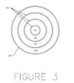
- FIG. 3is a plan view of the filter mechanism 105 for the preferred form of the invention.
- FIG. 4is a cross-sectional view of the filter mechanism.
- FIG. 5is a cross-sectional view of each of the three layers 110 , 110 B of FIG. 4 .
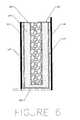
- FIG. 6is a cross-sectional view of each of the layer 110 A of FIG. 4 .
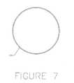
- FIG. 7is a plan view of the filter mechanism 105 for a First Modified Form of the Invention.
- FIG. 8is a sectional view of the filter mechanism of the First Modified Form of the Invention.
- FIG. 9is a plan view of a Second Modified Form of the Invention.
- FIG. 10is a horizontal sectional view of a Second Modified Form of the Invention.
- FIG. 11is a sectional view of a Third Modified Form of the Invention.
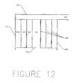
- FIG. 12is a sectional view of the filter mechanism 201 in the Third Modified Form of the Invention.
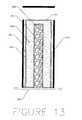
- FIG. 13is a detailed sectional view of a part of filter cell 211 in the Third Modified Form of the Invention.
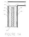
- FIG. 14is a detailed sectional view of filter cell 211 A in the Third Modified Form of the Invention.
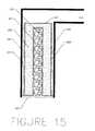
- FIG. 15is a detailed section view of a filter insert 201 which consists of only one filter cell.
- the present inventionis a system for removing oils from stormwater runoff by using filtration.
- the conventional prior artrelies on gravity separation to remove oils from stormwater runoff. Free oils can be removed by this method, but emulsified and dissolved oils cannot.
- the present inventionmakes use of a fine filter media to trap those oils that cannot be removed in a conventional gravity separator. Used in conjunction with a gravity separator such as those described in U.S. Pat. Nos. 5,746,911 and 8,264,835, both to Pank, the present invention comprises a two stage process for the removal of oils from runoff water.
- FIGS. 1 to 6illustrate the preferred form of the invention.
- the new filterhas two opposing sides, one of which sides comprises the upper ends of the cells 110 , 110 A and 110 B of FIGS. 5 and 6 and the other of which sides comprises the lower end of said cells 110 , 110 A and 110 B.
- FIGS. 1 and 2there is a tank 100 that has an inlet conduit such as pipe 101 , a clean water outlet conduit such as pipe 102 , and an overflow outlet conduit such as pipe 103 .
- the clean water outlet pipe 102is at a substantially lower elevation than the inlet pipe 101
- the overflow outlet pipe 103is at the same elevation as the inlet pipe 101 .
- the clean water outlet conduit 102 and overflow outlet conduit 103may be kept separate to maintain segregated waste streams, or may be combined into a single outlet conduit.
- the filter mechanism 105is shown in FIGS. 3 and 4 .
- the filter mechanismis divided into concentric filter cells 110 and 110 A by inner walls 111 , and surrounded by outer wall 112 .
- Outer wall 112is taller than inner walls 111 .
- a reservoir 113with one side, in this case the bottom side, perforated.
- the reservoiris formed by outer wall 112 and the tops of the filter cells 110 and 110 A.
- Each interior filter cell 110is constructed as shown in FIG. 5 .
- the inner walls 11constitute the vertical boundaries of the cell, and perforated plate 125 constitutes the floor.
- the entire filter mechanism 105is held above the floor of tank 100 in any suitable way.
- a drain 124is fastened along the inside of the inner walls 111 .
- the drainis bounded by barrier 123 , which separates the drain 124 from a fine filter media 122 .
- Barrier 123is a geotextile or similar device that is fine enough to retain fine filter media 122 , but porous enough to allow water to pass through it.
- a second barrier 121separates the fine filter media 122 from a coarse material 120 .
- barrier 121is also a geotextile or similar device that is fine enough to retain fine filter media 122 , but porous enough to allow water to pass through it. Barrier 121 extends along the top of the fine filter media 122 to the inner wall 111 .
- the tank 100is a large chamber. Inside of the large chamber is a smaller chamber 112 containing the filter cells 110 and 110 A.
- Each filter cellsuch as those shown in FIGS. 5 and 6 , has a first passageway along the vertical center line of the cell and containing the first filter media 120 .
- a second passagewayis in the form of drain 124 .
- the fine filtering mediacomprises the second filtration media.
- the exterior filter cell 110 Ais shown in FIG. 6 .
- An inner wall 111forms one vertical boundary, while the outer wall 112 forms the other vertical boundary.
- Perforated plate 125 , drain 124 , barrier 123 , fine filter media 122 , barrier 121 , and coarse material 120are arranged as they are in the aforementioned interior filter cell 110 .
- the wateris passed from spillway 101 A into reservoir 113 above filter mechanism 105 . Because the oil entering the system is emulsified or dissolved, the oil does not remain on top of the water in reservoir 113 , but is instead mixed throughout the water. From reservoir 113 , the water flows into coarse material 120 . Coarse material 120 has a large volume of voids and provides little resistance to the flow of water, thus the water is distributed evenly throughout coarse material 120 .
- Fine filter media 122provides significantly more resistance to flow than does coarse material 120 . Furthermore, the finer particles create a more tortuous flow path, allowing for longer contact time between the runoff water and the fine filter media 122 , and therefore more efficient pollutant removal. As the fine filter media 122 slowly becomes saturated, the filtered runoff water will then penetrate barrier 123 and enter drain 124 .
- Drain 124is simply an open space that allows the water to flow down along interior wall 111 or outer wall 112 to perforated plate 125 .
- the waterflows through the perforations in plate 125 and back into tank 100 .
- tank 100From tank 100 , the water flows between spacers 106 and enters the clean water outlet pipe 102 .
- the clean water outlet pipe 102delivers the filtered runoff water to a sewer or stream.
- the fine filter media 122restricts the flow through filter cells 110 and 110 A, and therefore restricts the flow through filter mechanism 105 .
- the overflow outlet pipe 103accepts the excess water from the surface of the reservoir 113 through overflow inlet 103 A.
- Overflow pipe 103delivers the unfiltered water to a sewer or stream. This can be the same sewer or stream that clean water outlet pipe 102 discharges to, or it can be a different discharge point.
- the present inventioncan be used with a single filter cell.
- the tank 100 , inlet pipe 101 with spillway 101 A, clean water outlet pipe 102 , and overflow outlet pipe 103 with inlet 103 Aare unchanged, and are arranged as shown in FIGS. 1 and 2 for the preferred form of the invention.
- the filter mechanism 105is positioned in the same place within the invention, but the interior components are altered to create a single filter cell.
- FIGS. 7 and 8illustrate this First Modified Form of the present invention.
- the filter mechanism 105is bounded by outer wall 131 , which also creates reservoir 113 .
- the outer wall 139contains the single filter cell as shown in FIG. 8 , and perforated plate 135 constitutes the floor.
- the entire filter mechanism 105is again raised above the floor of tank 100 in any suitable way.
- a drain 134is fastened along the inside of the outer wall 139 .
- the drainis bounded by barrier 133 , which separates the drain 134 from a fine filter media 132 .
- Barrier 133is a geotextile or similar device that is fine enough to retain fine filter media 132 , but porous enough to allow water to pass through it.
- barrier 131separates the fine filter media 132 from a coarse material 130 .
- barrier 131is also a geotextile or similar device that is fine enough to retain fine filter media 132 , but porous enough to allow water to pass through it. Barrier 131 extends along the top of the fine filter media 132 to the outer wall 139 .
- the wateris passed from spillway 101 A into reservoir 113 above filter mechanism 105 . Because the oil entering the system is emulsified or dissolved, the oil does not remain on top of the water in reservoir 113 A, but is instead mixed throughout the water. From reservoir 113 A, the water flows into coarse material 130 . Coarse material 130 has a large volume of voids and provides little resistance to the flow of water, thus the water is distributed evenly throughout coarse material 130 .
- Fine filter media 132provides significantly more resistance to flow than does coarse material 130 . Furthermore, the finer particles create a more tortuous flow path, allowing for longer contact time between the runoff water and the fine filter media 132 , and therefore more efficient pollutant removal. As the fine filter media 132 slowly becomes saturated, the filtered runoff water will then penetrate barrier 133 and enter drain 134 .
- Drain 134is simply an open space that allows the water to flow down along outer wall 139 to perforated plate 135 .
- the waterflows through the perforations in plate 135 and back into tank 100 .
- tank 100From tank 100 , the water flows between spacers 106 A and enters the clean water outlet pipe 102 .
- the clean water outlet pipe 102delivers the filtered runoff water to a sewer or stream.
- the fine filter media 132restricts the flow through the single filter cell, and therefore restricts the flow through filter mechanism 105 .
- the overflow outlet pipe 103accepts the excess water from the surface of the reservoir 113 through overflow outlet 103 A.
- Overflow pipe 103delivers the unfiltered water to a sewer or stream. This can be the same sewer or stream that clean water outlet pipe 102 discharges to, or it can be a different discharge point.
- the present inventioncan be configured with a single outlet pipe that conveys the filtered water during low flow rate conditions and the unfiltered water during high flow rate conditions to the same discharge point.
- FIGS. 9 and 10show the arrangement of the tank and associated pipes for this form of the Invention.
- FIGS. 9 and 10there is a tank 100 that has an inlet pipe 101 and an outlet pipe 141 .
- the outlet pipe 140is at a substantially lower elevation than the inlet pipe 101 .
- the filter mechanism 105remains unchanged from the Preferred Form of the Invention.
- the wateris passed from spillway 101 A into reservoir 113 above filter mechanism 105 . Because the oil entering the system is emulsified or dissolved, the oil does not remain on top of the water in reservoir 113 , but is instead mixed throughout the water. From reservoir 113 , the water flows into coarse material 120 . Coarse material 120 has a large volume of voids and provides little resistance to the flow of water, thus the water is distributed evenly throughout coarse material 120 .
- Fine filter media 122provides significantly more resistance to flow than does coarse material 120 . Furthermore, the finer particles create a more tortuous flow path, allowing for longer contact time between the runoff water and the fine filter media 122 , and therefore more efficient pollutant removal. As the fine filter media 122 slowly becomes saturated, the filtered runoff water will then penetrate barrier 123 and enter drain 124 .
- Drain 124is simply an open space that allows the water to flow down along interior wall 111 or outer wall 112 to perforated plate 125 .
- the waterflows through the perforations in plate 125 and back into tank 100 .
- the waterenters the clean water outlet pipe 102 .
- the clean water outlet pipe 102delivers the filtered runoff water to a sewer or stream.
- the fine filter media 122restricts the flow through filter cells 110 and 110 A, and therefore restricts the flow through filter mechanism 105 .
- the excess waterflows over the outer wall 112 of filter mechanism 105 , and down to the floor of tank 100 .
- the untreated waterenters the single outlet pipe 141 .
- the outlet pipe 141delivers the filtered runoff water to a sewer or stream.
- FIGS. 11-14show the configuration of the invention for this form.
- tank 200has a sump below the outlet pipe 203 , and filter insert 201 is set in that sump.
- Inlet pipe 202allows water to flow into tank 200 and into the sump.
- water level in tank 200exceeds the elevation of clean water outlet pipe 203 , water will begin to flow through filter insert 201 and into outlet pipe 203 .
- waterwill be allowed to exit tank 200 through overflow pipe 204 .
- FIG. 12shows a section of filter insert 201 and its connection to clean water outlet pipe 203 .
- Filter insert 201is bounded by outer walls 210 , which connect to clean water outlet pipe 203 .
- Concentric rings 211are defined within filter insert 201 by inner walls 212 , with the outer ring 211 A bound by the inner wall 212 on one side and outer wall 210 on the other.
- Waterenters filter insert 201 through a permeable bottom 213 , and flows upward through filter top 214 . Once clean water flows through filter top 214 , it then flows by gravity through clean water outlet 203 .
- FIG. 13shows a detailed section of one of the concentric rings 211 that make up filter insert 201 .
- the ring 211is bounded on each side by inner wall 212 .
- Waterenters the filter cell through permeable bottom 213 and flows into the coarse filter media 220 . Because of the high permeability of media 220 , the water distributes itself evenly through coarse media 220 and flows from there, through permeable barrier 221 , and into fine media 222 . The water flows mainly horizontally through fine media 222 , but near the top of the cell, water may also flow vertically through fine media 222 . Once through the fine media 222 , water passes through permeable barrier 223 and into vertical drain 224 . Once in drain 224 , the water flows upward alongside wall 212 until it reaches the top of the filter cell. At the top of the cell, water can flow over wall 212 onto the top of the adjacent cell, until it reaches the outermost filter cell.
- FIG. 14shows the outermost filter cell 211 A.
- the filter cell 211 Afunctions the same way as the other cells 211 , with the exception that it is bordered by one inner wall 212 and the outer wall 210 of filter insert 201 .
- Water again enters the cell through permeable barrier 213flows into coarse media 220 , flows through permeable barrier 221 into fine media 222 , through permeable barrier 223 into vertical drain 224 , and upward to the top of the cell. From the top of filter cell 211 A, the filtered water leaves the system through clean water outlet pipe 203 .
- wateralso enters cell 211 A from adjacent filter cells 211 by flowing over inner walls 212 . This water also leaves filter cell 211 A through an outlet conduit such as clean water outlet pipe 203 .
- FIG. 15shows a cross section of filter insert 201 in a final modified form of the invention, in which filter insert 201 consists solely of one filter cell.
- the filter cellis bounded on each side by outer walls 212 , and is in direct communication with clean water outlet pipe 203 .
- Water enters the filter cell through permeable barrier 213flows into coarse media 220 , enters fine media 222 through permeable barrier 221 , enters vertical drain 224 through permeable barrier 223 , and flows upward until it leaves the filter cell through clean water outlet pipe 203 .
Landscapes
- Chemical & Material Sciences (AREA)
- Chemical Kinetics & Catalysis (AREA)
- Thermal Sciences (AREA)
- Physics & Mathematics (AREA)
- Hydrology & Water Resources (AREA)
- Water Supply & Treatment (AREA)
- Engineering & Computer Science (AREA)
- Life Sciences & Earth Sciences (AREA)
- Public Health (AREA)
- Health & Medical Sciences (AREA)
- Environmental & Geological Engineering (AREA)
- Organic Chemistry (AREA)
- Filtration Of Liquid (AREA)
- Filtering Of Dispersed Particles In Gases (AREA)
Abstract
Description
Claims (44)
Priority Applications (4)
| Application Number | Priority Date | Filing Date | Title |
|---|---|---|---|
| US10/040,611US6869528B2 (en) | 2001-02-26 | 2002-01-09 | Filtering system for runoff water |
| PCT/US2002/003786WO2002068085A1 (en) | 2001-02-26 | 2002-02-06 | Filtering system for runoff water |
| CA002399157ACA2399157C (en) | 2001-02-26 | 2002-02-06 | Filtering system for runoff water |
| US10/306,606US7182856B2 (en) | 2001-02-26 | 2002-11-27 | Stormwater treatment train |
Applications Claiming Priority (2)
| Application Number | Priority Date | Filing Date | Title |
|---|---|---|---|
| US27106501P | 2001-02-26 | 2001-02-26 | |
| US10/040,611US6869528B2 (en) | 2001-02-26 | 2002-01-09 | Filtering system for runoff water |
Related Child Applications (1)
| Application Number | Title | Priority Date | Filing Date |
|---|---|---|---|
| US10/306,606Continuation-In-PartUS7182856B2 (en) | 2001-02-26 | 2002-11-27 | Stormwater treatment train |
Publications (2)
| Publication Number | Publication Date |
|---|---|
| US20020117435A1 US20020117435A1 (en) | 2002-08-29 |
| US6869528B2true US6869528B2 (en) | 2005-03-22 |
Family
ID=26717227
Family Applications (1)
| Application Number | Title | Priority Date | Filing Date |
|---|---|---|---|
| US10/040,611Expired - LifetimeUS6869528B2 (en) | 2001-02-26 | 2002-01-09 | Filtering system for runoff water |
Country Status (3)
| Country | Link |
|---|---|
| US (1) | US6869528B2 (en) |
| CA (1) | CA2399157C (en) |
| WO (1) | WO2002068085A1 (en) |
Cited By (22)
| Publication number | Priority date | Publication date | Assignee | Title |
|---|---|---|---|---|
| US20050069386A1 (en)* | 2003-03-11 | 2005-03-31 | Henry Happel | Golf course green storm water filter |
| US20050178719A1 (en)* | 2004-02-12 | 2005-08-18 | Pank Thomas E. | Filter in the form of a roll and the method of making the same |
| US20060016767A1 (en)* | 2004-07-23 | 2006-01-26 | I.S.C. Environmental, Inc. | Fluid filter system and related method |
| US20070023352A1 (en)* | 2005-01-07 | 2007-02-01 | Pank Thomas E | System for feeding a liquid fluid through a filter |
| US20070256966A1 (en)* | 2006-05-04 | 2007-11-08 | Siviter Terry L | Stormwater bioretention filtration system with overflow/bypass capability |
| US20080245710A1 (en)* | 2006-12-08 | 2008-10-09 | Ohio University | Exfiltration apparatus |
| US20080277327A1 (en)* | 2007-05-09 | 2008-11-13 | Contech Stormwater Solutions, Inc. | Stormwater Filter Assembly |
| US20090045128A1 (en)* | 2007-08-15 | 2009-02-19 | Christopher Adam Murray | Filter For Removing Sediment From Water |
| US7582216B2 (en) | 2007-08-22 | 2009-09-01 | Imbrium Systems Corp. | Water treatment and bypass system |
| US7743573B1 (en) | 2007-09-17 | 2010-06-29 | Engineering Innovations, LLC | Roofing composition |
| US20110056890A1 (en)* | 2009-09-09 | 2011-03-10 | Contech Construction Products Inc. | Stormwater filtration apparatus, system and method |
| US8221618B2 (en)* | 2007-08-15 | 2012-07-17 | Monteco Ltd. | Filter for removing sediment from water |
| US8287726B2 (en) | 2007-08-15 | 2012-10-16 | Monteco Ltd | Filter for removing sediment from water |
| US8333885B1 (en) | 2009-06-19 | 2012-12-18 | Paul Anthony Iorio | Stormwater filtration system and method with pretreatment capability |
| US8512555B1 (en) | 2006-08-23 | 2013-08-20 | Contech Engineered Solutions LLC | Filter assembly, system and method |
| US9162169B1 (en) | 2012-09-01 | 2015-10-20 | Guy Alan Stivers | Flexible filter hand bags for catch basins |
| US9175463B1 (en) | 2012-09-01 | 2015-11-03 | Guy Alan Stivers | Methods for modular catch basins |
| US9487421B2 (en) | 2012-09-01 | 2016-11-08 | Jeff Howard Coffman | Modular high performance bioswale and water treatment system and method |
| US9593477B1 (en) | 2012-09-01 | 2017-03-14 | Guy Alan Stivers | Modular catch basins |
| US9839864B2 (en) | 2015-10-27 | 2017-12-12 | Jeff Mason | Enclosed media fluid filtration device |
| US10563392B2 (en) | 2015-08-11 | 2020-02-18 | Mmt, Inc. | Stormwater biofiltration system and method |
| US20220023778A1 (en)* | 2020-07-27 | 2022-01-27 | Pre-Con Products | Double-Filter Basket for StormWater Retention System Drain |
Families Citing this family (6)
| Publication number | Priority date | Publication date | Assignee | Title |
|---|---|---|---|---|
| US6533941B2 (en)* | 2001-08-14 | 2003-03-18 | George R. Butler | Flow through drain filter for a stormwater or wastewater catch basin |
| DE50307913D1 (en)* | 2002-12-30 | 2007-09-20 | Bosch Gmbh Robert | FUEL FILTER |
| GB0508483D0 (en)* | 2005-04-27 | 2005-06-01 | Robinson Iain A S | Storm drain filter |
| WO2008104030A1 (en)* | 2007-03-01 | 2008-09-04 | Jack Mckenzie Droomer | Separating solid or particulate matter from a fluid flow, in particular, a stormwater flow, and further with an overflow bypass |
| AU2008221239B2 (en)* | 2008-02-29 | 2015-05-14 | Jack Mckenzie Droomer | Separating solid or particulate matter from a fluid flow, in particular, a stormwater flow, and further with an overflow bypass |
| EP2363185B1 (en)* | 2010-03-03 | 2013-01-02 | Maximilian Blomeier | Regenerable filter element with support layers |
Citations (67)
| Publication number | Priority date | Publication date | Assignee | Title |
|---|---|---|---|---|
| US210113A (en) | 1878-11-19 | Improvement in cistern-filters | ||
| US300612A (en)* | 1884-06-17 | Filter | ||
| US575478A (en)* | 1897-01-19 | Carl haefner | ||
| US620316A (en)* | 1899-02-28 | Filter | ||
| US631128A (en) | 1899-01-21 | 1899-08-15 | William M Ricketts | Rain-water filter. |
| US745497A (en) | 1902-08-15 | 1903-12-01 | John P Mcandrews | Filter. |
| US789968A (en) | 1904-06-21 | 1905-05-16 | Silver & Company | Filter. |
| US945989A (en)* | 1909-02-24 | 1910-01-11 | George Vol Sponenbarger | Filter. |
| US988391A (en)* | 1909-07-30 | 1911-04-04 | Henry Shillington | Apparatus for filtering water, sewage, and the like. |
| US1033329A (en)* | 1912-02-26 | 1912-07-23 | Owen Laughlin | Filter. |
| US1090283A (en)* | 1912-12-26 | 1914-03-17 | Merton L Crandall | Water filterer or strainer. |
| US1140726A (en)* | 1914-01-05 | 1915-05-25 | William F Warden | Filter. |
| US1793080A (en)* | 1931-02-17 | glover | ||
| US1956132A (en)* | 1932-05-10 | 1934-04-24 | Philabert Frank | Apparatus for the treatment of liquids |
| US2405838A (en)* | 1944-03-01 | 1946-08-13 | Lawson Archibald | Liquid separator apparatus |
| US2723035A (en)* | 1954-09-15 | 1955-11-08 | Edward B Anderson | Oil filter |
| US2742160A (en) | 1951-06-14 | 1956-04-17 | Joseph W Fogwell | Filter cartridge |
| US3807570A (en) | 1972-09-29 | 1974-04-30 | Carborundum Co | Slot depth filter element |
| US4045346A (en) | 1976-02-24 | 1977-08-30 | Swaskey Henry S | Basement sewer trap |
| US4261823A (en) | 1979-07-26 | 1981-04-14 | Summit Engineering Corporation | Storm drain catch basin |
| US4297219A (en) | 1980-01-28 | 1981-10-27 | The Kbi Corp. | Temporary stream filtration system |
| US4708792A (en) | 1985-10-17 | 1987-11-24 | Takara Kogyo Co., Ltd. | Filter medium |
| US4752396A (en) | 1985-10-07 | 1988-06-21 | Brunswick Corporation | Multi-strand wound filter with variant cross sectional density |
| US4861465A (en) | 1988-01-25 | 1989-08-29 | Augustyniak Stanley D | Anti-reverse siphoning water circulating system for aquariums |
| US4985148A (en) | 1990-02-08 | 1991-01-15 | Fibresep Ltd. | Improved separator tank construction |
| US5122270A (en) | 1989-04-11 | 1992-06-16 | Seitz-Filter-Werke Theo & Geo Seitz Gmbh & Co. | Filter cartridge or filter module consisting of flexible deep filter material |
| US5133619A (en) | 1991-03-18 | 1992-07-28 | Murfae George W | Storm water filtration system for use with conventional storm water collection sewers |
| US5160039A (en) | 1991-10-04 | 1992-11-03 | Perry Colburn | Bio-tube aquatic filter |
| US5223154A (en) | 1991-11-01 | 1993-06-29 | Emcon Northwest, Inc. | System for filtering liquids in a catch basin using filters in series and overflow channels |
| US5269921A (en) | 1989-04-11 | 1993-12-14 | Seitz-Filter-Werke Gmbh & Co. | Filter cartridge or filter module consisting of flexible deep filter material |
| US5431813A (en)* | 1994-02-14 | 1995-07-11 | Daniels; Jack E. | Water filtering bottle |
| US5433845A (en) | 1994-06-03 | 1995-07-18 | Newberry Tanks & Equipment, Inc. | Flow control bypass basin apparatus |
| US5480254A (en) | 1993-11-19 | 1996-01-02 | Autry; James L. | Storm drain box filter and method of use |
| US5511904A (en) | 1991-02-06 | 1996-04-30 | Van Egmond; John | Storm water infiltration |
| US5531888A (en) | 1993-07-28 | 1996-07-02 | Vsb Vogelsberger Umwelttechnischer Anlagenbau Gmbh | Arrangement for separation of coarse matter and/or bulky solids in rainwater relief structures |
| US5562819A (en) | 1994-04-19 | 1996-10-08 | Fresh Creek Technologies, Inc. | Apparatus for trapping, signalling presence of and collecting debris in waterways |
| US5632889A (en) | 1995-06-09 | 1997-05-27 | Tharp; Gary D. | Filter cartridge for separating liquid hydrocarbons from water |
| US5643445A (en) | 1995-08-28 | 1997-07-01 | Billias; Charles | Removable storm water screen and overflow device |
| US5650065A (en) | 1996-01-22 | 1997-07-22 | Sewell; William J. | Skimmer cover for dry well in a catch basin |
| US5707527A (en)* | 1996-04-30 | 1998-01-13 | Stormwater Treatment Llc | Apparatus and method for treating storm water runoff |
| US5725760A (en) | 1996-04-29 | 1998-03-10 | Stormceptor Corporation | Enhanced separator tank |
| US5744048A (en) | 1996-03-01 | 1998-04-28 | Storm Water Systems, Inc. | Clog resistant storm drain filter |
| US5759415A (en) | 1991-10-02 | 1998-06-02 | Vortechnics, Inc. | Method and apparatus for separating floating and non-floating particulate from rainwater drainage |
| US5770057A (en) | 1996-08-12 | 1998-06-23 | John Meunier Inc. | Overflow water screening apparatus |
| US5779888A (en) | 1995-09-04 | 1998-07-14 | Baramy Engineering Pty. Ltd. | Filtering apparatus |
| US5788848A (en) | 1994-06-17 | 1998-08-04 | Cds Tech Ltd | Apparatus and methods for separating solids from flowing liquids or gases |
| US5814216A (en) | 1997-02-07 | 1998-09-29 | John Meunier Inc. | Waste water contaminant segregating unit for sewer conduits |
| US5820762A (en) | 1995-06-20 | 1998-10-13 | Bamer; Jonathan Michael | Filter insert for a storm drain |
| US5849181A (en) | 1997-06-02 | 1998-12-15 | Stormceptor Corporation | Catch basin |
| US5904842A (en) | 1995-08-28 | 1999-05-18 | Billias; Charles | Removable storm water devices |
| US5958226A (en) | 1997-12-29 | 1999-09-28 | Fleischmann; Charles R. | Storm drain filter with removable debris tray |
| US6027639A (en)* | 1996-04-30 | 2000-02-22 | Stormwater Treatment Llc | Self-cleaning siphon-actuated radial flow filter basket |
| US6062767A (en) | 1998-02-09 | 2000-05-16 | Kizhnerman; Samuil | Storm water receptor system |
| US6068765A (en) | 1999-03-26 | 2000-05-30 | Stormceptor Corporation | Separator tank |
| US6077448A (en) | 1996-10-07 | 2000-06-20 | Wilkinson Heavy Precast | Oil/grit interceptor |
| US6080308A (en) | 1998-10-26 | 2000-06-27 | Ecodrain Ab | Water purification arrangement for drain water catch basins |
| US6086758A (en) | 1998-11-13 | 2000-07-11 | Pactec, Inc. | Storm drain liner |
| US6086756A (en) | 1996-10-23 | 2000-07-11 | Ecosol Pty Ltd | Gross pollution filter |
| US6096200A (en) | 1997-11-27 | 2000-08-01 | Baramy Engineering Pty. Ltd. | Filtering apparatus |
| US6099729A (en) | 1996-03-01 | 2000-08-08 | Parker-Hannifin Corporation | Coreless non-metallic filter element |
| US6190545B1 (en) | 1998-04-01 | 2001-02-20 | Remedial Solutions, Inc. | Drainwater treatment system for use in a horizontal passageway |
| US6200484B1 (en) | 2000-03-16 | 2001-03-13 | Mcinnis Stephen J. | Surface water filtration apparatus |
| US6217757B1 (en)* | 2000-04-26 | 2001-04-17 | Charles R. Fleischmann | Storm drain filter with vertical screens |
| US6241881B1 (en) | 1997-11-21 | 2001-06-05 | University Of South Australia | Pollution separator and filtration apparatus |
| US6251269B1 (en) | 1999-03-18 | 2001-06-26 | Dennis J. Johnson | Modular filtration system having removable filter element |
| US6270653B1 (en) | 1997-01-09 | 2001-08-07 | Imperial College Of Science, Technology & Medicine | Method of controlling asphaltene precipitation in a fluid |
| US6315897B1 (en) | 2000-05-23 | 2001-11-13 | Eastern States Associates | Rain water run-off filtering system |
Family Cites Families (6)
| Publication number | Priority date | Publication date | Assignee | Title |
|---|---|---|---|---|
| EP0370026B1 (en)* | 1987-06-10 | 1994-08-17 | Conoco Specialty Products Inc. | Liquid separator |
| EP0401276A4 (en)* | 1988-02-19 | 1991-11-13 | Conoco Specialty Products Inc. | Separating liquids |
| US4933094A (en)* | 1988-09-30 | 1990-06-12 | Conoco Specialty Products, Inc. | Method and apparatus for separating liquid components from a liquid mixture |
| US5158678A (en)* | 1990-09-28 | 1992-10-27 | Broussard Paul C Sr | Water clarification method and apparatus |
| US5492622A (en)* | 1990-09-28 | 1996-02-20 | Broussard; Paul C. | Water clarification apparatus |
| US5565101A (en)* | 1995-02-15 | 1996-10-15 | Spokane Industries, Inc. | Oil and water separator |
- 2002
- 2002-01-09USUS10/040,611patent/US6869528B2/ennot_activeExpired - Lifetime
- 2002-02-06WOPCT/US2002/003786patent/WO2002068085A1/ennot_activeApplication Discontinuation
- 2002-02-06CACA002399157Apatent/CA2399157C/ennot_activeExpired - Lifetime
Patent Citations (67)
| Publication number | Priority date | Publication date | Assignee | Title |
|---|---|---|---|---|
| US1793080A (en)* | 1931-02-17 | glover | ||
| US300612A (en)* | 1884-06-17 | Filter | ||
| US575478A (en)* | 1897-01-19 | Carl haefner | ||
| US620316A (en)* | 1899-02-28 | Filter | ||
| US210113A (en) | 1878-11-19 | Improvement in cistern-filters | ||
| US631128A (en) | 1899-01-21 | 1899-08-15 | William M Ricketts | Rain-water filter. |
| US745497A (en) | 1902-08-15 | 1903-12-01 | John P Mcandrews | Filter. |
| US789968A (en) | 1904-06-21 | 1905-05-16 | Silver & Company | Filter. |
| US945989A (en)* | 1909-02-24 | 1910-01-11 | George Vol Sponenbarger | Filter. |
| US988391A (en)* | 1909-07-30 | 1911-04-04 | Henry Shillington | Apparatus for filtering water, sewage, and the like. |
| US1033329A (en)* | 1912-02-26 | 1912-07-23 | Owen Laughlin | Filter. |
| US1090283A (en)* | 1912-12-26 | 1914-03-17 | Merton L Crandall | Water filterer or strainer. |
| US1140726A (en)* | 1914-01-05 | 1915-05-25 | William F Warden | Filter. |
| US1956132A (en)* | 1932-05-10 | 1934-04-24 | Philabert Frank | Apparatus for the treatment of liquids |
| US2405838A (en)* | 1944-03-01 | 1946-08-13 | Lawson Archibald | Liquid separator apparatus |
| US2742160A (en) | 1951-06-14 | 1956-04-17 | Joseph W Fogwell | Filter cartridge |
| US2723035A (en)* | 1954-09-15 | 1955-11-08 | Edward B Anderson | Oil filter |
| US3807570A (en) | 1972-09-29 | 1974-04-30 | Carborundum Co | Slot depth filter element |
| US4045346A (en) | 1976-02-24 | 1977-08-30 | Swaskey Henry S | Basement sewer trap |
| US4261823A (en) | 1979-07-26 | 1981-04-14 | Summit Engineering Corporation | Storm drain catch basin |
| US4297219A (en) | 1980-01-28 | 1981-10-27 | The Kbi Corp. | Temporary stream filtration system |
| US4752396A (en) | 1985-10-07 | 1988-06-21 | Brunswick Corporation | Multi-strand wound filter with variant cross sectional density |
| US4708792A (en) | 1985-10-17 | 1987-11-24 | Takara Kogyo Co., Ltd. | Filter medium |
| US4861465A (en) | 1988-01-25 | 1989-08-29 | Augustyniak Stanley D | Anti-reverse siphoning water circulating system for aquariums |
| US5269921A (en) | 1989-04-11 | 1993-12-14 | Seitz-Filter-Werke Gmbh & Co. | Filter cartridge or filter module consisting of flexible deep filter material |
| US5122270A (en) | 1989-04-11 | 1992-06-16 | Seitz-Filter-Werke Theo & Geo Seitz Gmbh & Co. | Filter cartridge or filter module consisting of flexible deep filter material |
| US4985148A (en) | 1990-02-08 | 1991-01-15 | Fibresep Ltd. | Improved separator tank construction |
| US5511904A (en) | 1991-02-06 | 1996-04-30 | Van Egmond; John | Storm water infiltration |
| US5133619A (en) | 1991-03-18 | 1992-07-28 | Murfae George W | Storm water filtration system for use with conventional storm water collection sewers |
| US5759415A (en) | 1991-10-02 | 1998-06-02 | Vortechnics, Inc. | Method and apparatus for separating floating and non-floating particulate from rainwater drainage |
| US5160039A (en) | 1991-10-04 | 1992-11-03 | Perry Colburn | Bio-tube aquatic filter |
| US5223154A (en) | 1991-11-01 | 1993-06-29 | Emcon Northwest, Inc. | System for filtering liquids in a catch basin using filters in series and overflow channels |
| US5531888A (en) | 1993-07-28 | 1996-07-02 | Vsb Vogelsberger Umwelttechnischer Anlagenbau Gmbh | Arrangement for separation of coarse matter and/or bulky solids in rainwater relief structures |
| US5480254A (en) | 1993-11-19 | 1996-01-02 | Autry; James L. | Storm drain box filter and method of use |
| US5431813A (en)* | 1994-02-14 | 1995-07-11 | Daniels; Jack E. | Water filtering bottle |
| US5562819A (en) | 1994-04-19 | 1996-10-08 | Fresh Creek Technologies, Inc. | Apparatus for trapping, signalling presence of and collecting debris in waterways |
| US5433845A (en) | 1994-06-03 | 1995-07-18 | Newberry Tanks & Equipment, Inc. | Flow control bypass basin apparatus |
| US5788848A (en) | 1994-06-17 | 1998-08-04 | Cds Tech Ltd | Apparatus and methods for separating solids from flowing liquids or gases |
| US5632889A (en) | 1995-06-09 | 1997-05-27 | Tharp; Gary D. | Filter cartridge for separating liquid hydrocarbons from water |
| US5820762A (en) | 1995-06-20 | 1998-10-13 | Bamer; Jonathan Michael | Filter insert for a storm drain |
| US5643445A (en) | 1995-08-28 | 1997-07-01 | Billias; Charles | Removable storm water screen and overflow device |
| US5904842A (en) | 1995-08-28 | 1999-05-18 | Billias; Charles | Removable storm water devices |
| US5779888A (en) | 1995-09-04 | 1998-07-14 | Baramy Engineering Pty. Ltd. | Filtering apparatus |
| US5650065A (en) | 1996-01-22 | 1997-07-22 | Sewell; William J. | Skimmer cover for dry well in a catch basin |
| US6099729A (en) | 1996-03-01 | 2000-08-08 | Parker-Hannifin Corporation | Coreless non-metallic filter element |
| US5744048A (en) | 1996-03-01 | 1998-04-28 | Storm Water Systems, Inc. | Clog resistant storm drain filter |
| US5725760A (en) | 1996-04-29 | 1998-03-10 | Stormceptor Corporation | Enhanced separator tank |
| US5707527A (en)* | 1996-04-30 | 1998-01-13 | Stormwater Treatment Llc | Apparatus and method for treating storm water runoff |
| US6027639A (en)* | 1996-04-30 | 2000-02-22 | Stormwater Treatment Llc | Self-cleaning siphon-actuated radial flow filter basket |
| US5770057A (en) | 1996-08-12 | 1998-06-23 | John Meunier Inc. | Overflow water screening apparatus |
| US6077448A (en) | 1996-10-07 | 2000-06-20 | Wilkinson Heavy Precast | Oil/grit interceptor |
| US6086756A (en) | 1996-10-23 | 2000-07-11 | Ecosol Pty Ltd | Gross pollution filter |
| US6270653B1 (en) | 1997-01-09 | 2001-08-07 | Imperial College Of Science, Technology & Medicine | Method of controlling asphaltene precipitation in a fluid |
| US5814216A (en) | 1997-02-07 | 1998-09-29 | John Meunier Inc. | Waste water contaminant segregating unit for sewer conduits |
| US5849181A (en) | 1997-06-02 | 1998-12-15 | Stormceptor Corporation | Catch basin |
| US6241881B1 (en) | 1997-11-21 | 2001-06-05 | University Of South Australia | Pollution separator and filtration apparatus |
| US6096200A (en) | 1997-11-27 | 2000-08-01 | Baramy Engineering Pty. Ltd. | Filtering apparatus |
| US5958226A (en) | 1997-12-29 | 1999-09-28 | Fleischmann; Charles R. | Storm drain filter with removable debris tray |
| US6062767A (en) | 1998-02-09 | 2000-05-16 | Kizhnerman; Samuil | Storm water receptor system |
| US6190545B1 (en) | 1998-04-01 | 2001-02-20 | Remedial Solutions, Inc. | Drainwater treatment system for use in a horizontal passageway |
| US6080308A (en) | 1998-10-26 | 2000-06-27 | Ecodrain Ab | Water purification arrangement for drain water catch basins |
| US6086758A (en) | 1998-11-13 | 2000-07-11 | Pactec, Inc. | Storm drain liner |
| US6251269B1 (en) | 1999-03-18 | 2001-06-26 | Dennis J. Johnson | Modular filtration system having removable filter element |
| US6068765A (en) | 1999-03-26 | 2000-05-30 | Stormceptor Corporation | Separator tank |
| US6200484B1 (en) | 2000-03-16 | 2001-03-13 | Mcinnis Stephen J. | Surface water filtration apparatus |
| US6217757B1 (en)* | 2000-04-26 | 2001-04-17 | Charles R. Fleischmann | Storm drain filter with vertical screens |
| US6315897B1 (en) | 2000-05-23 | 2001-11-13 | Eastern States Associates | Rain water run-off filtering system |
Cited By (39)
| Publication number | Priority date | Publication date | Assignee | Title |
|---|---|---|---|---|
| US20050069386A1 (en)* | 2003-03-11 | 2005-03-31 | Henry Happel | Golf course green storm water filter |
| US6979148B2 (en)* | 2003-03-11 | 2005-12-27 | Henry Happel | Golf course green storm water filter |
| US20050178719A1 (en)* | 2004-02-12 | 2005-08-18 | Pank Thomas E. | Filter in the form of a roll and the method of making the same |
| US20060016767A1 (en)* | 2004-07-23 | 2006-01-26 | I.S.C. Environmental, Inc. | Fluid filter system and related method |
| US7799235B2 (en)* | 2004-07-23 | 2010-09-21 | Contech Stormwater Solutions, Inc. | Fluid filter system and related method |
| US20110062088A1 (en)* | 2004-07-23 | 2011-03-17 | Olson Norman L | Fluid filter system and related method |
| US7708149B2 (en) | 2005-01-07 | 2010-05-04 | Thomas E. Pank | System for feeding a liquid fluid through a filter |
| US20070023352A1 (en)* | 2005-01-07 | 2007-02-01 | Pank Thomas E | System for feeding a liquid fluid through a filter |
| US7425261B2 (en)* | 2006-05-04 | 2008-09-16 | Americast, Inc. | Stormwater bioretention filtration system with overflow/bypass capability |
| US7625485B2 (en)* | 2006-05-04 | 2009-12-01 | Americast, Inc. | Stormwater bioretention filtration system with overflow/bypass capability |
| US20070256966A1 (en)* | 2006-05-04 | 2007-11-08 | Siviter Terry L | Stormwater bioretention filtration system with overflow/bypass capability |
| US8512555B1 (en) | 2006-08-23 | 2013-08-20 | Contech Engineered Solutions LLC | Filter assembly, system and method |
| US20080245710A1 (en)* | 2006-12-08 | 2008-10-09 | Ohio University | Exfiltration apparatus |
| US9017550B2 (en)* | 2006-12-08 | 2015-04-28 | Ohio University | Exfiltration apparatus |
| US20080277327A1 (en)* | 2007-05-09 | 2008-11-13 | Contech Stormwater Solutions, Inc. | Stormwater Filter Assembly |
| US8110099B2 (en) | 2007-05-09 | 2012-02-07 | Contech Stormwater Solutions Inc. | Stormwater filter assembly |
| US20090045128A1 (en)* | 2007-08-15 | 2009-02-19 | Christopher Adam Murray | Filter For Removing Sediment From Water |
| US8123935B2 (en)* | 2007-08-15 | 2012-02-28 | Monteco Ltd. | Filter for removing sediment from water |
| US8221618B2 (en)* | 2007-08-15 | 2012-07-17 | Monteco Ltd. | Filter for removing sediment from water |
| US8287726B2 (en) | 2007-08-15 | 2012-10-16 | Monteco Ltd | Filter for removing sediment from water |
| US7582216B2 (en) | 2007-08-22 | 2009-09-01 | Imbrium Systems Corp. | Water treatment and bypass system |
| US8065854B1 (en) | 2007-09-17 | 2011-11-29 | Engineering Innovations, LLC | Roofing composition |
| US7743573B1 (en) | 2007-09-17 | 2010-06-29 | Engineering Innovations, LLC | Roofing composition |
| US10626592B2 (en) | 2008-01-16 | 2020-04-21 | Contech Engineered Solutions LLC | Filter for removing sediment from water |
| US8333885B1 (en) | 2009-06-19 | 2012-12-18 | Paul Anthony Iorio | Stormwater filtration system and method with pretreatment capability |
| US8658044B2 (en) | 2009-09-09 | 2014-02-25 | Contech Engineered Solutions LLC | Stormwater filtration apparatus, system and method |
| US20110056890A1 (en)* | 2009-09-09 | 2011-03-10 | Contech Construction Products Inc. | Stormwater filtration apparatus, system and method |
| US9162169B1 (en) | 2012-09-01 | 2015-10-20 | Guy Alan Stivers | Flexible filter hand bags for catch basins |
| US9175463B1 (en) | 2012-09-01 | 2015-11-03 | Guy Alan Stivers | Methods for modular catch basins |
| US9487421B2 (en) | 2012-09-01 | 2016-11-08 | Jeff Howard Coffman | Modular high performance bioswale and water treatment system and method |
| US9593477B1 (en) | 2012-09-01 | 2017-03-14 | Guy Alan Stivers | Modular catch basins |
| US10563392B2 (en) | 2015-08-11 | 2020-02-18 | Mmt, Inc. | Stormwater biofiltration system and method |
| US11124959B2 (en) | 2015-08-11 | 2021-09-21 | Mmt, Inc. | Stormwater biofiltration system and method |
| US9839864B2 (en) | 2015-10-27 | 2017-12-12 | Jeff Mason | Enclosed media fluid filtration device |
| US11020688B2 (en) | 2015-10-27 | 2021-06-01 | Advanced Drainage Systems, Inc. | Enclosed media fluid filtration device |
| US11253799B2 (en) | 2015-10-27 | 2022-02-22 | Advanced Drainage Systems, Inc. | Enclosed media fluid filtration device |
| US12311290B2 (en) | 2015-10-27 | 2025-05-27 | Advanced Drainage Systems, Inc. | Enclosed media fluid filtration device |
| US20220023778A1 (en)* | 2020-07-27 | 2022-01-27 | Pre-Con Products | Double-Filter Basket for StormWater Retention System Drain |
| US11980835B2 (en)* | 2020-07-27 | 2024-05-14 | Foley Products Company, Llc | Double-filter basket for stormwater retention system drain |
Also Published As
| Publication number | Publication date |
|---|---|
| CA2399157C (en) | 2009-05-12 |
| CA2399157A1 (en) | 2002-09-06 |
| WO2002068085A1 (en) | 2002-09-06 |
| US20020117435A1 (en) | 2002-08-29 |
Similar Documents
| Publication | Publication Date | Title |
|---|---|---|
| US6869528B2 (en) | Filtering system for runoff water | |
| US7022243B2 (en) | Apparatus for treating storm water | |
| AU703425B2 (en) | Method and apparatus for separating floating and non-floating particulate from rainwater drainage | |
| US7582216B2 (en) | Water treatment and bypass system | |
| US4261823A (en) | Storm drain catch basin | |
| NZ287820A (en) | Self-cleaning fluid borne solids separating screen for stormwater | |
| US7182856B2 (en) | Stormwater treatment train | |
| AU2018288385B2 (en) | "device for improving water quality" | |
| US7285211B2 (en) | Process and system for separating solids from combined sewer overflows | |
| US20110049029A1 (en) | Apparatus to Separate Light Fluids, Heavy Fluids, and/or Sediment from a Fluid Stream | |
| SK154794A3 (en) | Separator of sludge and oil | |
| AU2011298805B2 (en) | Separator for separating a light liquid-water mixture and method for separating a light liquid-water mixture | |
| KR101687180B1 (en) | Natural type nonpoint pollution decrease infiltration trench | |
| AU2006220392B2 (en) | System for feeding a liquid fluid through a filter | |
| AU2005316557B2 (en) | Apparatus for separating particulates from a fluid stream | |
| KR102215767B1 (en) | Non-point contaminant reducing device for treatment of first rain water | |
| JP3341210B2 (en) | Separation device for mixture of oils in water | |
| JPH09296499A (en) | Sedimentation and penetration equipment |
Legal Events
| Date | Code | Title | Description |
|---|---|---|---|
| AS | Assignment | Owner name:WESTMINSTER UNION BANK, MARYLAND Free format text:SECURITY AGREEMENT;ASSIGNOR:PANK, THOMAS E.;REEL/FRAME:014108/0006 Effective date:20030430 | |
| AS | Assignment | Owner name:WESTMINSTER UNION BANK, MARYLAND Free format text:SECURITY INTEREST;ASSIGNOR:PANK, THOMAS E.;REEL/FRAME:016536/0280 Effective date:20050203 | |
| STCF | Information on status: patent grant | Free format text:PATENTED CASE | |
| AS | Assignment | Owner name:WESTMINSTER UNION BANK, MARYLAND Free format text:AMENDMENT TO COLLATERAL ASSIGNMENT OF PATENTS AS SECURITY;ASSIGNOR:THOMAS E. PANK;REEL/FRAME:016945/0201 Effective date:20051222 | |
| AS | Assignment | Owner name:WESTMINSTER UNION BANK, MARYLAND Free format text:COLLATERAL ASSIGNMENT OF PATENTS AS SECURITY AND SECURITY AGREEMENT;ASSIGNOR:THOMAS E. PANK;REEL/FRAME:018120/0279 Effective date:20060803 | |
| REMI | Maintenance fee reminder mailed | ||
| FPAY | Fee payment | Year of fee payment:4 | |
| SULP | Surcharge for late payment | ||
| FPAY | Fee payment | Year of fee payment:8 | |
| FPAY | Fee payment | Year of fee payment:12 | |
| SULP | Surcharge for late payment | Year of fee payment:11 |