US6868309B1 - Dialysis machine with symmetric multi-processing (SMP) control system and method of operation - Google Patents
Dialysis machine with symmetric multi-processing (SMP) control system and method of operationDownload PDFInfo
- Publication number
- US6868309B1 US6868309B1US09/961,735US96173501AUS6868309B1US 6868309 B1US6868309 B1US 6868309B1US 96173501 AUS96173501 AUS 96173501AUS 6868309 B1US6868309 B1US 6868309B1
- Authority
- US
- United States
- Prior art keywords
- processors
- dialysis machine
- bus
- processor
- control system
- Prior art date
- Legal status (The legal status is an assumption and is not a legal conclusion. Google has not performed a legal analysis and makes no representation as to the accuracy of the status listed.)
- Expired - Fee Related, expires
Links
- 238000000502dialysisMethods0.000titleclaimsabstractdescription87
- 238000000034methodMethods0.000titleclaimsabstractdescription70
- 238000012545processingMethods0.000titleclaimsabstractdescription14
- 230000015654memoryEffects0.000claimsabstractdescription69
- 230000008569processEffects0.000claimsabstractdescription55
- 239000008280bloodSubstances0.000claimsdescription22
- 210000004369bloodAnatomy0.000claimsdescription22
- 230000004044responseEffects0.000claimsdescription3
- 238000004891communicationMethods0.000abstractdescription12
- 230000000694effectsEffects0.000description8
- 230000008901benefitEffects0.000description7
- 238000013461designMethods0.000description7
- 230000006870functionEffects0.000description6
- XLYOFNOQVPJJNP-UHFFFAOYSA-NwaterSubstancesOXLYOFNOQVPJJNP-UHFFFAOYSA-N0.000description6
- 239000012528membraneSubstances0.000description4
- 230000000737periodic effectEffects0.000description4
- 238000002360preparation methodMethods0.000description4
- 238000001514detection methodMethods0.000description3
- 230000001276controlling effectEffects0.000description2
- 230000008878couplingEffects0.000description2
- 238000010168coupling processMethods0.000description2
- 238000005859coupling reactionMethods0.000description2
- 238000012423maintenanceMethods0.000description2
- 230000001105regulatory effectEffects0.000description2
- 238000012360testing methodMethods0.000description2
- 238000002560therapeutic procedureMethods0.000description2
- 239000003053toxinSubstances0.000description2
- 231100000765toxinToxicity0.000description2
- 108700012359toxinsProteins0.000description2
- 238000012546transferMethods0.000description2
- UIIMBOGNXHQVGW-DEQYMQKBSA-MSodium bicarbonate-14CChemical compound[Na+].O[14C]([O-])=OUIIMBOGNXHQVGW-DEQYMQKBSA-M0.000description1
- 208000027418Wounds and injuryDiseases0.000description1
- 239000002253acidSubstances0.000description1
- 230000006978adaptationEffects0.000description1
- 230000006399behaviorEffects0.000description1
- 230000017531blood circulationEffects0.000description1
- 230000006378damageEffects0.000description1
- 230000001419dependent effectEffects0.000description1
- 238000010586diagramMethods0.000description1
- 239000003814drugSubstances0.000description1
- 229940079593drugDrugs0.000description1
- 230000009977dual effectEffects0.000description1
- 231100001261hazardousToxicity0.000description1
- 230000006872improvementEffects0.000description1
- 208000014674injuryDiseases0.000description1
- 229910052500inorganic mineralInorganic materials0.000description1
- 210000003734kidneyAnatomy0.000description1
- 230000003907kidney functionEffects0.000description1
- 230000007257malfunctionEffects0.000description1
- 230000007246mechanismEffects0.000description1
- 239000011707mineralSubstances0.000description1
- 235000010755mineralNutrition0.000description1
- 238000002156mixingMethods0.000description1
- 239000000203mixtureSubstances0.000description1
- 238000012986modificationMethods0.000description1
- 230000004048modificationEffects0.000description1
- 230000002093peripheral effectEffects0.000description1
- 238000011084recoveryMethods0.000description1
- 230000003252repetitive effectEffects0.000description1
- 238000001223reverse osmosisMethods0.000description1
- 150000003839saltsChemical class0.000description1
- 239000000126substanceSubstances0.000description1
- 208000024891symptomDiseases0.000description1
Images

Classifications
- G—PHYSICS
- G16—INFORMATION AND COMMUNICATION TECHNOLOGY [ICT] SPECIALLY ADAPTED FOR SPECIFIC APPLICATION FIELDS
- G16H—HEALTHCARE INFORMATICS, i.e. INFORMATION AND COMMUNICATION TECHNOLOGY [ICT] SPECIALLY ADAPTED FOR THE HANDLING OR PROCESSING OF MEDICAL OR HEALTHCARE DATA
- G16H20/00—ICT specially adapted for therapies or health-improving plans, e.g. for handling prescriptions, for steering therapy or for monitoring patient compliance
- G16H20/40—ICT specially adapted for therapies or health-improving plans, e.g. for handling prescriptions, for steering therapy or for monitoring patient compliance relating to mechanical, radiation or invasive therapies, e.g. surgery, laser therapy, dialysis or acupuncture
- G—PHYSICS
- G05—CONTROLLING; REGULATING
- G05B—CONTROL OR REGULATING SYSTEMS IN GENERAL; FUNCTIONAL ELEMENTS OF SUCH SYSTEMS; MONITORING OR TESTING ARRANGEMENTS FOR SUCH SYSTEMS OR ELEMENTS
- G05B2219/00—Program-control systems
- G05B2219/30—Nc systems
- G05B2219/34—Director, elements to supervisory
- G05B2219/34466—Bad circuits, watchdog, alarm, indication
- Y—GENERAL TAGGING OF NEW TECHNOLOGICAL DEVELOPMENTS; GENERAL TAGGING OF CROSS-SECTIONAL TECHNOLOGIES SPANNING OVER SEVERAL SECTIONS OF THE IPC; TECHNICAL SUBJECTS COVERED BY FORMER USPC CROSS-REFERENCE ART COLLECTIONS [XRACs] AND DIGESTS
- Y10—TECHNICAL SUBJECTS COVERED BY FORMER USPC
- Y10T—TECHNICAL SUBJECTS COVERED BY FORMER US CLASSIFICATION
- Y10T436/00—Chemistry: analytical and immunological testing
- Y10T436/11—Automated chemical analysis
- Y10T436/115831—Condition or time responsive
- Y—GENERAL TAGGING OF NEW TECHNOLOGICAL DEVELOPMENTS; GENERAL TAGGING OF CROSS-SECTIONAL TECHNOLOGIES SPANNING OVER SEVERAL SECTIONS OF THE IPC; TECHNICAL SUBJECTS COVERED BY FORMER USPC CROSS-REFERENCE ART COLLECTIONS [XRACs] AND DIGESTS
- Y10—TECHNICAL SUBJECTS COVERED BY FORMER USPC
- Y10T—TECHNICAL SUBJECTS COVERED BY FORMER US CLASSIFICATION
- Y10T436/00—Chemistry: analytical and immunological testing
- Y10T436/11—Automated chemical analysis
- Y10T436/117497—Automated chemical analysis with a continuously flowing sample or carrier stream
Definitions
- This inventionrelates generally to the field of dialysis and machines for performing dialysis therapy. More particularly, the invention relates to a computer control system for a dialysis machine and a method of operation thereof in which a plurality of processors are provided which form a tightly coupled, symmetric multi-processing computing platform for the dialysis machine.
- Dialysisis a treatment for persons suffering from inadequate kidney function.
- a dialysis machineis an artificial kidney machine that treats the blood of a dialysis patient.
- Dialysis machinestypically incorporate an extracorporeal blood circuit having a semipermeable dialyzer membrane. During dialysis therapy, blood from the patient is circulated through the extracorporeal circuit to the dialyzer membrane, where toxins and excess water are transported through the dialyzer membrane into a dialysate solution. The treated blood is then returned to the patient.
- Dialysis machinesalso typically include a dialysate preparation system.
- This systemprepares a dialysate solution by mixing concentrated chemicals (typically a mixture of sodium bicarbonate, an acid solution, and additional minerals and salts) with reverse-osmosis filtered water.
- concentrated chemicalstypically a mixture of sodium bicarbonate, an acid solution, and additional minerals and salts
- dialysis equipmenthave specific safety criteria that are required by regulatory agencies.
- One of these criteriais single-fault tolerance.
- Single-fault tolerancerequires that no single point of failure of the instrumentation shall expose the patient to a hazardous condition.
- dialysis equipmenthave satisfied the criterion, in part, by designing in redundant components where indicated by risk management methodologies (e.g. hazard analysis etc.).
- the redundancy of componentsincludes aspects of the computer or processor-based control system for the machine.
- all dialysis machine implementations to datehave incorporated a computer control system based on redundant processors which execute control and safety instructions in the form of computer code. Accordingly, redundant processors permit a remaining processor to continue operation of the dialysis machine if one of the redundant processors fails.
- the failure of a processor or computermay be characterized as a Byzantine failure.
- the term “Byzantine” in the present documentrefers to a failure whose symptoms cannot be characterized. Stated differently, processor behavior during a Byzantine failure can be arbitrary and therefore potentially unsafe to the patient. As a result, two independent redundant processors may reduce the risk exposure to Byzantine failures when compared to a single processor implementation since the remaining processor may detect the malfunction and take control of the dialysis machine.
- Error detection in a redundant processor architecturemay therefore be provided by allowing the properly running processor to become a master and the faulty processor to become a slave.
- An example of a redundant processor computer control system for a dialysis machineis described in the patent of Rodney S. Kenley et al., U.S. Pat. No. 5,788,851, assigned to the assignee of the present invention, which is incorporated by reference herein.
- Two redundant processorssignificantly increase an instrument's cost and complexity over a single processor design, which would be the design of choice but for the safety and redundancy requirements explained above. These increased costs include a redundant CPU board, a more complex backplane, additional software development, increased maintenance, and increased costs for servicing the machine.
- redundant processorsmay require separate dedicated CPU buses for each processor.
- a failuresuch as a bus lock-up condition is more likely on a system with two busses rather than one bus because a failure may occur on either bus.
- a failure on one processormay not affect the other processor if the busses are truly independent.
- a single processor designmust, however, satisfy the same safety criterion as mentioned above, namely single-fault tolerance. Because a single processor alone has a single point of failure, i.e., the processor itself, another means must be used to detect Byzantine failures in the processor and provide for safe operation of the instrument regardless of a failure of the processor or the processor's board.
- a patent issued to Rosa et al. U.S. Pat. No. 5,618,441('441 patent), the contents of which are incorporated by reference, proposes a single microprocessor design for a dialysis machine.
- the solutionis a control system computing platform for a dialysis machine that uses a Symmetric Multi-Processing (SMP) architecture.
- SMPSymmetric Multi-Processing
- the SMP architecturetightly couples multiple (e.g., 2 or more) independent processors by sharing memory between the processors.
- a computer failuresuch as a bus failure on the circuit card for example
- one of the distributed hardware watchdogsmay reset the computer including the processors. Therefore, it is believed that the use of the SMP type architecture represents an improvement and distinct departure from the Rosa et al. '441 patent since the SMP design uses two physical processors (in the preferred embodiment) whereas the Rosa et al. '441 patent uses a single physical processor.
- the SMP architecturehas the following advantages:
- An SMP controllermay use a single main memory shared by both CPUs in order to facilitate communication between the processors. As a result, cost is reduced by eliminating the expense of redundant components such as redundant processors, memory and memory busses.
- the parallel processors in an SMP controllermay use a common CPU bus coupled to the shared memory, or each processor may have their own CPU bus coupled to a cache that is then linked with other processors through a separate memory bus.
- redundant designsrequire separate redundant memories in order to maintain true redundancy resulting in additional cost.
- the two, or in general n SMP processorsprovide the advantage of high throughput without the added cost of redundant memory.
- the SMP controllerprovides increased processor throughput when compared with single processor controllers by operating on N processes in parallel without requiring redundant memory and without having a single point of failure in the controller or computer. Therefore, the SMP controller uniquely combines the advantages of increased throughput provided by redundant processor controllers while maintaining the reduced cost advantages of a single processor controller.
- the SMP architecturemay also connect to host adapter boards for interfacing with various dialysis machine and extracorporeal circuits.
- these devicesmay include active and passive components such as control devices, sensors, motors, heaters, pumps and valve drivers.
- the extracorporeal circuit devicesmay control the flow of blood in the dialysis machine.
- the SMP architecturemay be conveniently implemented into a modular computer chassis of an SMP processing board. Maintenance costs may be reduced as a result because a single board may be replaced more economically than replacing the entire controller.
- a safety consideration with SMP architectureis that the processor board itself, wherein the N tightly coupled processors may reside, may be single fault tolerant by using a watch dog timer circuit. Since there are no longer two fully independent redundant processors in the SMP architecture, such as those described in the Kenley et al. '851 patent cited above, a Byzantine failure on the processor board (a bus lockup condition for example) may be rectified with a watchdog timer resetting the processors. This prevents software execution from stopping when the CPU or I/O bus locks up.
- Multiple hardware watchdogs distributed (with respect to the system boards) in an SMP architecturemay remedy a controller failure in a novel and much less expensive manner than in a redundant processor architecture.
- the CPUsmay periodically reset the watchdog timers before the timers “time-out”. Accordingly, the periodic receipt of the watchdog reset signals from the CPUs may indicate that the CPUs are operating properly.
- the watchdog timersmay time-out by counting down to zero or alternatively to a predetermined number. For example, the CPU may fail to reset the watchdog timer due to a Byzantine failure such as a CPU or bus lock up condition.
- the watchdog timermay send a reset signal to reset the CPUs in order to correct the failure. Therefore, should the watchdog timer circuit fail to receive the periodic reset signals within the expected time interval(s), the CPUs may be reset. Since the watchdogs are physically independent of the processor board, the watchdogs are unaffected by Byzantine failures on it. Additionally, because there are multiple watchdogs in the system, the watchdog circuitry itself is single-fault tolerant.
- the watchdog timer circuitsmay respond to a controller failure by delivering a control signal to these various dialysis machine and extracorporeal circuits.
- the watchdog reset signalmay also be sent to the various hardware components such as the extracorporeal circuits of the dialysis machine in order to place the system in a safe mode.
- the control signalmay effectively de-energize the extracorporeal control and hydraulics devices to cause the dialysis machine to assume the safe patient mode.
- the safe modemay also shut off the flow of blood to the patient from the dialysis machine in order to prevent any damaged or unsafe blood from flowing to the patient. For example, the flow of blood to the patient may be stopped by disabling the blood pump and closing a clamp in the venous line. A failure of the controller therefore effectively results in the dialysis machine entering the safe patient mode.
- an improved control system for a dialysis machineis described.
- the improved control systemis single fault tolerant by utilizing multiple watchdog circuits in an SMP architecture.
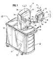
- FIG. 1is a perspective view of a dialysis machine
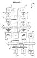
- FIG. 2illustrates a block diagram for one embodiment of the SMP architecture for the controller in the dialysis machine of FIG. 1 ;
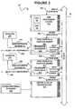
- FIG. 3illustrates one embodiment of distributing the SMP architecture into modular circuit cards.
- FIG. 1illustrates an exemplary dialysis machine 10 shown in a perspective view.
- the dialysis machine 10includes a patient or user interface module 12 containing a touch screen display 14 and a set of hard keys 16 , 18 , 20 .
- the user interface module 12is connected to an SMP control system 90 for controlling the functions of the dialysis machine as shown in FIG. 2 in more detail.
- the dialysis machine 10 shown in FIG. 1has an integral water treatment 23 and dialysate preparation module 25 contained within a lower cabinet 22 .
- An extracorporeal blood circulation circuitis housed within an upper cabinet 32 .
- the integral water treatment 23 and dialysate preparation modules 25are described in detail in U.S. Pat. No. 5,591,344 to Kenley et al. and assigned to Aksys, Ltd., the assignee of the present invention, and in PCT application publication no. WO 96/25214. These references describe a preferred dialysis machine suitable for use in the home environment.
- the Kenley et al. U.S. Pat. No. 5,591,344 and published PCT application no. WO 96/25214are both fully incorporated by reference herein. Additionally, the manner in which the dialysate solutions are prepared and circulated through the dialysate circuit may be as described in the above-referenced Kenley et al. U.S. Pat. No. 5,591,344.
- Bloodis removed from the patient and introduced into an arterial line, and pumped by a blood pump to the blood chamber of a dialyzer 10 in the extracorporeal circuit within cabinet 32 .
- Blood-borne toxins and excess waterare removed from the blood through the membrane of the dialyzer, and the blood is returned to the patient via a venous line.
- the details of the dialysate preparation module 25 , water treatment module 23 , and extracorporeal blood circuitare discussed in Kenley et al. U.S. Pat. No. 5,591,344. Therefore, a detailed discussion of these aspects of the instrument is omitted.
- an SMP control system 90is shown. It will be readily apparent that the SMP control system 90 of the present invention could be used in many types of dialysis machines other than the one shown in FIG. 1 .
- the SMP control system 90may be used in the dialysis machines described in the patents to Grogan et al. U.S. Pat. No. 5,326,476 and Rosa et al. U.S. Pat. No. 5,618,441, the contents of which are incorporated by reference.
- the SMP control system 90 of the present inventioncould also be used in other machines currently marketed by Gambro, Cobe, Baxter Healthcare, Althin Medical, and others.
- FIG. 2illustrates a presently preferred architecture for a SMP control system 90 .
- the control system 90generally includes multiple tightly coupled central processing units (CPUs) 40 , 42 that share a common main memory 70 .
- Main memory 70may be RAM (Random Access Memory), PROM (Programmable Read Only Memory), hard drive, ASIC (Application Specific Integrated Circuit) or any other suitable storage device for storing program code and data.
- CPUs 40 and 42are shown, the SMP control system 90 may be extended to more CPUs such as 3, or more CPU's.
- the current version of the Windows NT, XP, ME, or 2000 operating systemmay support up to 32 processors.
- the SMP control systemmay be able to support more CPUs in the future.
- the processors in an SMP systemare identical or are from the same type of processor family. Nevertheless, it may be possible to use different models from the same processor family or even processors from different vendors. For example, processors from Intel, Motorola, Texas Instruments, AMD or any vendor may be used. Processors that support SMP are preferably used. Alternatively, extra circuitry may be added external to the processor in order to support SMP functions.
- the SMP control system 90may use a high performance memory bus 60 for high speed communications between the processors 40 , 42 and the main memory 70 .
- exemplary I/O devices 82 , 86may generally communicate on an I/O bus 80 rather than directly over the high performance communications (memory) bus 60 .
- Exemplary I/O devices 82 and 86may for example be, extracorporeal devices such as valves, pumps, heaters, lights and motors 120 as shown in FIG. 3 .
- One advantage of using the separate communications (memory) bus 60 and the separate I/O bus 80is that CPUs 40 , 42 may operate at a higher clock speed than the clock on the I/O bus 80 as is often the case.
- the I/O bus 80may be connected to the high performance bus 60 through a bus bridge 78 .
- the bus bridge 78may emulate a direct connection by performing any data formatting and data rate adaptation between the two buses.
- the I/O bus 80may interconnect exemplary I/O devices 82 , 86 to main memory 70 or CPUs 40 , 42 using bus bridge 78 .
- bus bridge 78may de-couple the I/O bus 80 from the high performance bus 60 when data transfer between these two busses is not required.
- CPU 40may be linked to a cache 48 via the local CPU address/data bus 44 .
- the second processor, CPU 42may be linked to a cache 50 via a local CPU address/data bus 46 .
- Caches 48 and 50may then be linked to the high performance communications (memory) bus 60 to facilitate communication between the processors.
- Caches 48 , 50can enhance processor 40 , 42 throughput by taking advantage of the highly repetitive and predictable computations executed in an application. For example, the most recently executed instructions, and therefore the most likely next executed instructions, may be stored in caches 48 , 50 in order to allow CPUs 40 , 42 fast access to the instructions. Consequently, caches 48 , 50 eliminate the need to access a slower device such as a hard drive or a main memory in order to retrieve recently executed instructions.
- This architecture shown for example in FIG. 2is a tightly coupled, shared memory, symmetric multi-processing (or simply symmetric multi-processing—SMP) hardware architecture using two or more symmetric physical processors, 40 and 42 in such a manner that they appear to act as a single logical processor to a software application.
- the architectureis characterized by the following properties.
- the SMP control system 90may link to the interface module 12 shown in FIG. 1 via the I/O bus 80 , PIC (Programmable Interrupt Controller) 72 , and I/O devices 82 , 86 for example.
- the PIC 72may connect to all external interrupt sources to arbitrate interrupt requests 92 , 94 for access to the CPUs 40 , 42 .
- I/O devices 82 , 86may interface with the CPUs 40 , 42 , PIC 72 , and the I/O bus 80 to provide supervisory control.
- the interface module 12shown in FIG. 1 in conjunction with the SMP control system 90 shown in FIG.
- the interface module 12may prompt the user to input commands and information.
- the user interface and method of operationis applicable to other types of medical instruments. For further details of the user interface, see U.S. Pat. No. 5,788,851 cited earlier.
- Hardware watchdog circuits 210 & 310are programmable hardware timers that have the capability of electrically resetting the computing platform should they time out. Watchdog timers 210 and 310 may interface with the CPUs 40 , 42 , a dedicated reset controller (not shown), the I/O bus 80 and the local CPU bus 60 . Watchdog timers 210 & 310 as shown in FIG. 2 may be reset by CPUs 40 & 42 in order to start the watchdog timers 210 & 310 onto a countdown. The watchdog timers 210 & 310 then count down towards zero from a predetermined amount of time.
- a hardware reset of watchdog timers 210 & 310normally occurs before the timer counts down to zero if there is no failure such as a bus (i.e., CPU bus 60 or I/O bus 80 ) lock-up condition preventing the CPUs 40 & 42 from resetting watchdog timers 210 & 310 .
- a busi.e., CPU bus 60 or I/O bus 80
- Other types of computer failuresmay include an interrupt failure, a memory failure, a disk failure, clock failure, a watchdog failure, a peripheral failure, a software failure and a CPU failure and any bus failure related to these and other components.
- any failuremay be deemed to be the result of any cause preventing CPUs 40 and 42 from resetting the watchdog timers 210 and 310 .
- CPUs 40 and 42periodically reset the watchdog timers 210 and 310 before the timers time-out.
- the periodic receipt of the signals by the watchdog timers 210 and 310 from the CPUs 40 and 42indicates that the CPUs 40 and 42 are operating properly.
- the watchdog timers 210 and 310are not reset and the watchdog timer times-out.
- the watchdog timers 210 and 310may time-out, for example, due to a CPU or bus lock up condition as previously stated.
- the watchdog timer 210 , 310may send a reset signal to reset CPUs 40 and 42 to force a system reboot.
- the watchdog timers 210 & 310may be reset at different intervals and have different count-down time periods in order to prevent double resets for example. Additionally, a reset controller or similar mechanism in either hardware or software would avoid a double reset.
- the watchdogs 210 and 310may be physically independent of the processor board 100 . As a result of being independent, watchdogs 210 and 310 are unaffected by Byzantine failures. Because there are multiple watchdogs in the system, the watchdog circuitry itself is single-fault tolerant. If one watchdog fails, then the other watchdog may reset the controller 90 in the event of a failure. In one exemplary embodiment as shown in FIG. 3 , multiple hardware watchdogs 210 and 310 are located on separate modular circuit boards 200 and 300 respectively. If the processor board suffers a Byzantine failure, the watchdogs 210 and 310 can still reset the system because they are physically independent of CPUs 40 and 42 .
- watchdog 210fails during operation then other watchdog 310 protects against processor failures. Analogously, if watchdog 310 fails during operation then other watchdog 210 protects against processor failures. Consequently, since the watchdogs provide a way to recover from a bus or processor failure, the present invention is single-fault tolerant. Additionally, the watchdog timer may, for example, be based on the Intel MCS 51/151/251 family of microcontrollers.
- the watchdog reset signals such as 240 and 340 shown in FIG. 3may also be sent to other hardware components of the dialysis machine 10 in order to control these components, or to place all electromechanical subsystems into a safe state.
- the watchdog timer circuits 210 and 310may respond to a controller 90 failure by delivering a control signal 240 and 340 to the extracorporeal circuit devices (e.g. blood pump and venous line clamp) and selected hydraulics control devices contained within the valves, motors and pumps 120 as shown in FIG. 3 . Consequently, the hardware watchdogs 210 , 310 may shut off the blood pump, motors, heaters and bypass values 120 in the dialyzer to assume the safe patient mode.
- the extracorporeal circuit devicese.g. blood pump and venous line clamp
- the safe modemay shut the flow of blood to the patient from the dialysis machine 10 in order to prevent any potentially unsafe blood from flowing to the patient.
- the safe modemay involve closing the arterial and venous clamps, stopping the arterial blood pump, the venous blood pump, and bypassing the flow of dialysate around the dialyzer by changing the state of the bypass valves. Therefore, a reset signal to the CPUs 40 and 42 effectively achieves the safe patient mode.
- the CPUs 40 , 42are reset in the absence of a controller failure, then there is no risk to the patient in any event because the dialysis machine is placed into a safe state. For example, if a failure on the watchdog timers 210 , 310 causes the CPUs 40 , 42 to reset, then the controller puts the dialysis machine 10 into a safe mode, so there is no risk of injury to the patient. After the controller is placed into a safe state, then the controller may perform a self-check, resolve any bus contention and resume normal dialysis operation. The self-check may include determining if all dialysis programming information is correct and verifying the programming information with the patient or user before resuming dialysis.
- access to the high performance (memory) bus 60 between CPUs 40 and 42 and caches 48 and 50may be arbitrated by one of several ways.
- the operating systemmay allocate bus access time to each processor 40 & 42 based on the allocation and timing of executable instructions to each processor. Since the operating system determines how the executable instructions are distributed between the processors 40 & 42 , then the operating system may also determine the most effective distribution of bus access to each processor based on instruction length and complexity.
- each processor 40 and 42may make a bus access request to, for example, a master bus controller in order to control access to the high performance bus 60 .
- the master bus controllermay then resolve multiple requests or any conflicting requests and integrate bus access requests with normal operating system bus access requests.
- Yet another technique for detecting and avoiding bus collisionsis to allow each processor 40 or 42 access to the high performance bus 60 based on either processor 40 or 42 first detecting activity on the bus 60 before driving the bus 60 . If no activity is sensed on the high performance bus 60 , then the processor 40 or 42 sensing no activity may take control of the bus 60 . If activity is detected on the high performance bus 60 , then, the processor 40 or 42 sensing the activity may wait a pre-determined amount of time to again detect bus activity, or until the bus is released. Accordingly, once a processor releases the high performance bus 60 , then another processor 40 or 42 may take control of the bus after detecting no activity.
- both processorstry to drive the bus 60 , then a protocol allowing a response or acknowledgement to a processor driving the bus will inform the processor if the message or command was received.
- the CPU driving the busmay not receive a response to the message or command because, for example both CPUs attempted to drive the bus causing a collision. Accordingly, both CPUs may release the bus and again attempt to drive the bus after performing the collision avoidance techniques above.
- An alternative technique for detecting a collision on the bus 60is to employ a dedicated collision detection circuit for informing the processors that the bus 60 is in use by one or more components. Once the component such as processor 40 or 42 receives a collision signal from the collision detector, the component may interrupt driving the bus 60 and release the bus for an amount of time statistically pre-determined to minimize collisions. Additionally, any combination of the above mentioned or well-known bus resolution techniques may be utilized.
- a processor errormay be detected during normal operation where the redundant processors may compare each other's computational results while executing command instructions. For example, if the results between the processors differ, then the processors may perform a self-test. Accordingly, if one processor fails the self test, then the remaining properly functioning processor may take control of the dialysis machine and reset the failed processor.
- an arbitrator circuitmay detect if there is a difference in the computational result of each processor. If there is a difference, then the arbitrator may then determine which processor is in error and assign control of the dialysis machine to the remaining, properly functioning processor.
- Element-to-memory communications arbitrationmay be performed on an equal time basis between elements. If any processor (i.e. CPU 40 , 42 ) reads physical memory address n, for example, then any other device such as an I/O device 82 , 86 may also read physical memory address n so that the same physical datum may be read twice. If, for example, processors 40 , 42 and/or I/O devices 82 , 86 access the main memory 70 simultaneously, then their access may be arbitrated so that each computing element (processor 40 , 42 or I/O device 82 , 86 ) receives an equal amount of element-to-memory communications bandwidth. Furthermore, the arbitration process may be transparent to the computing elements such as processors 40 , 42 . For further details, see UNIX Systems For Modern Architectures: Symmetric Multiprocessing And Caching For Kernel Programmers . Addison Wesley 1994, e.g. at section 8.2, page 152.
- FIG. 3illustrates the SMP control system 90 shown in FIG. 2 distributed among several modular circuit cards according to one embodiment of the present invention.
- an SMP processor board 100may be interconnected to an I/O bus 80 back plane.
- Exemplary CPUs 40 and 42may be mounted on the SMP processor board 100 .
- caches 48 , 50 , and PIC 72(shown in FIG. 2 ) may be connected to CPUs 40 , 42 via CPU bus 60 and may also be part of the SMP processor board 100 .
- main memory 70 and bus bridge 78(also shown in FIG. 2 ) may be mounted on the SMP processor board 100 .
- a reset line 150may link the SMP processor board 100 with the I/O bus 80 back plane in order to provide the reset signal to CPUs 40 and 42 from the watchdog timers 210 and 310 .
- the reset line 150may be coupled directly to CPUs 40 and 42 , or may be coupled through another device such as a reset controller (not shown) or PIC 72 .
- a host analog and adapter board 200 , 300may link to the I/O bus 80 via address, data, and other signals or buses.
- a hardware watchdog 210 , 310may be mounted on host analog and adapter boards 200 , 300 to interface with I/O bus 80 via a reset line 220 , 320 and a watchdog control line 230 , 330 .
- hardware watchdogs 210 , 310may interface to sensors 270 , 370 as well as other patient critical components of the dialysis machine 10 (shown in FIG.
- reset lines 220 , 320 , 330 , and 250 , 350may connect to processors 40 and 42 or alternatively to a reset controller on the SMP processor board 100 .
- reset lines 220 , 320 , 230 , 330 , 250 , 350may connect to PIC 72 or an interrupt I/O device such as I/O device 82 or 86 .
- Reset lines 250 , 350may be used to reset the devices on the host analog & adapter board 200 300 such as hardware watchdogs 210 , 310 .
- the signals from analog or digital sensors 270 , 370may interface to the analog/digital sensor bus 260 , 360 and then to I/O bus 80 via the host analog & adapter boards 200 , 300 .
- Analog or digital sensors 270 , 370may for example be conductivity sensors, pressure sensors, temperature sensors, or any other appropriate type of sensors or transducers.
- Reset lines 250 , 350may link the host analog and adapter board 200 , 300 with I/O bus 80 .
- FIG. 3illustrates a dialysis motor, heater and valve driver board 400 interfacing to I/O bus 80 , reset line 450 and extracorporeal device(s) 120 .
- Reset line 450may reset the extracorporeal devices 120 (valve, heater, motor and pumps etc.) coupled to the motor and valve driver board 400 .
- reset lines 250 , 350may therefore be used to reset the devices on the host analog & adapter boards 200 , 300 as well as.
- the exemplary SMP computer 90is shown distributed among four circuit boards, the SMP computer may be divided among greater or fewer than four circuit boards and may further depend on the physical lay-out of the dialysis machine 10 .
- An SMP operating systemmay coordinate access to the high performance bus 60 via controlling access by the processors 40 , 42 , memory 70 , and the bus bridge 78 .
- the SMP operating systemmay allow the SMP controller 90 to generally execute one or more processes by simultaneously executing or processing N instructions in parallel where N is the number of processors.
- a processmay be a software application, a module from a software application, a single instruction, an operating system command or any group of machine instructions, or other type or group of instruction.
- several processesmay be executed on separate processors, however, in another embodiment one process may also execute on more than one processor simultaneously by distributing instructions from a process amongst the processors.
- the SMP operating systemmay allow different processes to execute in parallel on different processors. Accordingly, n SMP processors may each execute different instructions from n different processes in order to execute the n processes simultaneously. In this embodiment, the SMP operating system executes different processes simultaneously and may be used where the operation of each process may be time critical. For example, one processor may execute a process for a safety function and another processor may execute a process for a control function.
- the net effect for an SMP system with n processorsis that up to n times as much work can be performed per unit of time when compared to a single or redundant processor system. If, however, a first process on one processor is dependent on a second process on another processor, then the first process may have to wait for the second process to finish.
- processesmay be executed sequentially.
- multiple instructions from the same processmay be distributed for execution among the n processors thereby reducing the execution time of any single process.
- n different instructions of any single processesmay be executing on n processors.
- a single-processor operating systemonly executes a single instruction or process at any instant in time.
- the single processor operating systemmerely creates the illusion of many virtual processes executing concurrently by rapidly switching execution between the different processes according to the single processor operating system's schedule. Therefore, in contrast to both the single processor and redundant processor systems, the SMP operating system and computer may execute a process more quickly because the SMP operating system may execute different instructions in a true parallel processing computer while using a single main memory.
- the SMP operating systemmay switch execution among processes using distributed instruction-scheduling policies. Additionally, an SMP operating system does not necessarily favor any of the n parallel processors. For example, the operating system may assign the first available processor to be used for executing the next instruction or process. If, however, processes are executed in sequence, then neither process is favored over another because the processes are executed independently.
- the SMP architecture and operating systemallows the presence of multiple physical processors to appear transparent to an application.
- an applicationexecutes on an SMP operating system
- the applicationis not necessarily aware that processes, commands, and instructions may be constantly scheduled on different physical processors by the SMP operating system.
- the applicationpreferably is not necessarily required to track or perform symmetric access to shared memory, rather, this function is performed by the operating system. Consequently, application software can simply be written as if it is to execute on a single “virtual” processor.
- the single-processor programming model used in the SMP controller 90is simpler than a programming model with redundant dedicated host and safety computing platforms.
- the redundant computer architecturehas a separate redundant memory for each controller whereas the SMP controller may function with a single memory.
- the CPUs in the SMP architecturedo not require redundant I/O busses whereas a redundant computer uses redundant I/O buses to interface with extra corporeal devices.
- the redundant dual processor type architectureis visible to application software and increases the complexity of the application software. For example, a significant portion of the redundant programming model is devoted to a synchronizing processes for distributing applications and processes on both processors as required in the '851 patent. In contrast, synchronization in the SMP operating system used in the SMP controller becomes trivial because the SMP operating system uses the single-processor programming model.
- independent and redundant processorsare different from an SMP system in that the redundant processors perform independent redundant tasks rather than load share as in the SMP architecture.
- the single-processor programming modelmay utilize two physical SMP processors sharing the work load, the SMP operating system and not the application manages processes between the processors.
- the redundant physical processor model of the '851 patentis undesirable due to the increased complexity and the resulting increased hardware and software costs.
- the single processor modelis undesirable because the application is required to manage different processes.
- the single processor controllerwill have less throughput than an SMP type computer assuming equivalent individual computers because the SMP architecture permits different processes to be executed simultaneously on different processors.
- a non-SMP operating systemcan be used on an SMP-enabled controller to achieve some degree of computing parallelism.
- a non-SMP O/Smight only run on one process, for example, on the first processor and multitask processes on that processor.
- the non-SMP operating systemcould then treat the second processor as a slave by executing different processes one at a time on the second processor such that the process must run to completion before starting the next application.
- the SMP enabled operating systemtruly treats all computing resources symmetrically.
- the SMP operating system and its subsystemscan be scheduled and executed on any processor in the system in exactly the same manner as the operating system schedules and executes processes.
- the number of CPUs in the SMPcan be generalized as “N” CPUs including 2, 3, 4, 32 or more CPUs as previously stated.
- the synchronization and distribution of the machine instructionsmay be performed by the operating system, or alternatively by dedicated hardware such as a dedicated programmable logic array, or a CPU. Additionally, the synchronization and distribution of the machine instructions may be performed by a software routine in conjunction with or without the operating system, a module to the operating system, or on another processor.
Landscapes
- Health & Medical Sciences (AREA)
- Nuclear Medicine, Radiotherapy & Molecular Imaging (AREA)
- Surgery (AREA)
- Urology & Nephrology (AREA)
- Engineering & Computer Science (AREA)
- Epidemiology (AREA)
- General Health & Medical Sciences (AREA)
- Medical Informatics (AREA)
- Primary Health Care (AREA)
- Public Health (AREA)
- External Artificial Organs (AREA)
Abstract
Description
- 1. The SMP architecture reduces cost over a redundant architecture by eliminating expensive redundant components because they are not necessary in order to provide single-fault tolerance.
- 2. The SMP architecture uses a parallel multiprocessor architecture for improved performance while retaining a “single processor-programming” model thereby significantly reducing the complexity of a software application when compared to a redundant architecture.
- 3. The SMP architecture increases performance over a single processor controller since both processors can share the processing work-load. For example, the processors can share the work-load by evenly balancing processor loading.
- (1) Tight coupling of
processors processors processors memory 70 can communicate directly with each other (typically through the common highperformance communications bus 60 although various types of switching networks may also be used). The high performance communications (memory)bus 60 may also interconnect withmain memory 70. Additionally, the high performance communications (memory)bus 60 may access an I/O bus 80 via abus bridge 78. - (2) There may be a single
main memory 70 that is global to all processors and shared by allprocessors processor caches memory 70 may be made of separate memory components such as memory integrated circuits while appearing as a single main memory. For example, multiple memory orvirtual memory components 70 may provide access toCPUs caches - (3) Access to the single
main memory 70 is symmetric and fair. In other words, any memory operation means the same thing whether performed by any processor (i.e.CPU 40,42) or any I/O device
- (1) Tight coupling of
Claims (24)
Priority Applications (1)
| Application Number | Priority Date | Filing Date | Title |
|---|---|---|---|
| US09/961,735US6868309B1 (en) | 2001-09-24 | 2001-09-24 | Dialysis machine with symmetric multi-processing (SMP) control system and method of operation |
Applications Claiming Priority (1)
| Application Number | Priority Date | Filing Date | Title |
|---|---|---|---|
| US09/961,735US6868309B1 (en) | 2001-09-24 | 2001-09-24 | Dialysis machine with symmetric multi-processing (SMP) control system and method of operation |
Publications (1)
| Publication Number | Publication Date |
|---|---|
| US6868309B1true US6868309B1 (en) | 2005-03-15 |
Family
ID=34275048
Family Applications (1)
| Application Number | Title | Priority Date | Filing Date |
|---|---|---|---|
| US09/961,735Expired - Fee RelatedUS6868309B1 (en) | 2001-09-24 | 2001-09-24 | Dialysis machine with symmetric multi-processing (SMP) control system and method of operation |
Country Status (1)
| Country | Link |
|---|---|
| US (1) | US6868309B1 (en) |
Cited By (56)
| Publication number | Priority date | Publication date | Assignee | Title |
|---|---|---|---|---|
| US20030226066A1 (en)* | 2002-03-28 | 2003-12-04 | Alan Weddle | Method for configuring a multiple channel discrete output module |
| US20040044902A1 (en)* | 2002-08-29 | 2004-03-04 | Luthi Peter O. | Method and apparatus for multi-level security implementation |
| US20040078627A1 (en)* | 2002-03-28 | 2004-04-22 | Alan Weddle | Configurable multiple channel discrete output module |
| US20040199824A1 (en)* | 2003-01-23 | 2004-10-07 | Werner Harter | Device for safety-critical applications and secure electronic architecture |
| US20070157052A1 (en)* | 2006-01-03 | 2007-07-05 | Alcatel | Protection of devices in a redundant configuration |
| US20080058697A1 (en)* | 2006-04-14 | 2008-03-06 | Deka Products Limited Partnership | Heat exchange systems, devices and methods |
| US20080125886A1 (en)* | 2006-11-03 | 2008-05-29 | Dennis Brian King | Redundant control systems and methods |
| US20080140163A1 (en)* | 2006-12-06 | 2008-06-12 | Keacher Jeffrey T | Telemetry device for a medical device programmer |
| US20080147145A1 (en)* | 2002-10-31 | 2008-06-19 | Medtronic, Inc. | Failsafe programming of implantable medical devices |
| US20080216898A1 (en)* | 2007-02-27 | 2008-09-11 | Deka Products Limited Partnership | Cassette System Integrated Apparatus |
| US20090008331A1 (en)* | 2007-02-27 | 2009-01-08 | Deka Products Limited Partnership | Hemodialysis systems and methods |
| US20090008306A1 (en)* | 2007-07-05 | 2009-01-08 | Baxter International Inc. | Extracorporeal dialysis ready peritoneal dialysis machine |
| US20090095679A1 (en)* | 2007-02-27 | 2009-04-16 | Deka Products Limited Partnership | Hemodialysis systems and methods |
| US20090101549A1 (en)* | 2007-02-27 | 2009-04-23 | Deka Products Limited Partnership | Modular assembly for a portable hemodialysis system |
| US20090309835A1 (en)* | 2008-06-11 | 2009-12-17 | Fresenius Medical Care Holdings, Inc. | User Interface Processing Device |
| US20090312694A1 (en)* | 2008-06-11 | 2009-12-17 | Baxter International Inc. | Distributed processing system and method for dialysis machines |
| US20100051529A1 (en)* | 2008-08-27 | 2010-03-04 | Deka Products Limited Partnership | Dialyzer cartridge mounting arrangement for a hemodialysis system |
| US20100051551A1 (en)* | 2007-02-27 | 2010-03-04 | Deka Products Limited Partnership | Reagent supply for a hemodialysis system |
| US20100056975A1 (en)* | 2008-08-27 | 2010-03-04 | Deka Products Limited Partnership | Blood line connector for a medical infusion device |
| US20100192686A1 (en)* | 2007-02-27 | 2010-08-05 | Deka Products Limited Partnership | Blood treatment systems and methods |
| US7967022B2 (en) | 2007-02-27 | 2011-06-28 | Deka Products Limited Partnership | Cassette system integrated apparatus |
| US20120145636A1 (en)* | 2010-12-10 | 2012-06-14 | Water Intellectual Properties, Inc. | High Efficiency Water Purification System |
| US8352034B2 (en) | 2011-02-18 | 2013-01-08 | Medtronic, Inc. | Medical device programmer with adjustable kickstand |
| US8393690B2 (en) | 2007-02-27 | 2013-03-12 | Deka Products Limited Partnership | Enclosure for a portable hemodialysis system |
| US8491184B2 (en) | 2007-02-27 | 2013-07-23 | Deka Products Limited Partnership | Sensor apparatus systems, devices and methods |
| US8532775B2 (en) | 2011-02-18 | 2013-09-10 | Medtronic, Inc. | Modular medical device programmer |
| US8894600B2 (en) | 2003-11-05 | 2014-11-25 | Baxter International Inc. | Hemodialysis system including on-line dialysate generation |
| CN104360913A (en)* | 2014-11-04 | 2015-02-18 | 长园深瑞继保自动化有限公司 | Monitoring module for computer operation system |
| US9028691B2 (en) | 2007-02-27 | 2015-05-12 | Deka Products Limited Partnership | Blood circuit assembly for a hemodialysis system |
| US9328969B2 (en) | 2011-10-07 | 2016-05-03 | Outset Medical, Inc. | Heat exchange fluid purification for dialysis system |
| EP2902046A4 (en)* | 2012-09-26 | 2016-05-11 | Terumo Corp | Controller for life support device and method for controlling same |
| US20160163208A1 (en)* | 2014-12-04 | 2016-06-09 | General Electric Company | System and method for collision avoidance |
| US9402945B2 (en) | 2014-04-29 | 2016-08-02 | Outset Medical, Inc. | Dialysis system and methods |
| US9440017B2 (en) | 2013-03-14 | 2016-09-13 | Baxter International Inc. | System and method for performing alternative and sequential blood and peritoneal dialysis modalities |
| US9517295B2 (en) | 2007-02-27 | 2016-12-13 | Deka Products Limited Partnership | Blood treatment systems and methods |
| US9545469B2 (en) | 2009-12-05 | 2017-01-17 | Outset Medical, Inc. | Dialysis system with ultrafiltration control |
| US9597442B2 (en) | 2007-02-27 | 2017-03-21 | Deka Products Limited Partnership | Air trap for a medical infusion device |
| US9724458B2 (en) | 2011-05-24 | 2017-08-08 | Deka Products Limited Partnership | Hemodialysis system |
| US9740178B2 (en) | 2013-03-14 | 2017-08-22 | GM Global Technology Operations LLC | Primary controller designation in fault tolerant systems |
| US9782596B2 (en) | 2003-06-11 | 2017-10-10 | Boston Scientific Neuromodulation Corporation | Server for communication with an implantable medical device |
| US9895502B2 (en) | 2012-09-26 | 2018-02-20 | Terumo Kabushiki Kaisha | Medical device and method for controlling same |
| US10201650B2 (en) | 2009-10-30 | 2019-02-12 | Deka Products Limited Partnership | Apparatus and method for detecting disconnection of an intravascular access device |
| US10537671B2 (en) | 2006-04-14 | 2020-01-21 | Deka Products Limited Partnership | Automated control mechanisms in a hemodialysis apparatus |
| IT201900021012A1 (en)* | 2019-11-12 | 2021-05-12 | Eurosets Srl | EQUIPMENT FOR CHECKING BIOMEDICAL DEVICES DURING EXTRA-BODY CIRCULATION AND RELATED SYSTEM |
| US11495334B2 (en) | 2015-06-25 | 2022-11-08 | Gambro Lundia Ab | Medical device system and method having a distributed database |
| US11534537B2 (en) | 2016-08-19 | 2022-12-27 | Outset Medical, Inc. | Peritoneal dialysis system and methods |
| US11696978B2 (en) | 2008-01-23 | 2023-07-11 | Deka Products Limited Partnership | Medical treatment system and methods using a plurality of fluid lines |
| US11724013B2 (en) | 2010-06-07 | 2023-08-15 | Outset Medical, Inc. | Fluid purification system |
| US11752248B2 (en) | 2008-01-23 | 2023-09-12 | Deka Products Limited Partnership | Medical treatment system and methods using a plurality of fluid lines |
| US12026271B2 (en) | 2014-05-27 | 2024-07-02 | Deka Products Limited Partnership | Control systems and methods for blood or fluid handling medical devices |
| US12194213B2 (en) | 2011-11-04 | 2025-01-14 | Deka Products Limited Partnership | Medical treatment system and methods using a plurality of fluid lines |
| US12201762B2 (en) | 2018-08-23 | 2025-01-21 | Outset Medical, Inc. | Dialysis system and methods |
| US12303631B2 (en) | 2011-11-04 | 2025-05-20 | Deka Products Limited Partnership | Medical treatment system and methods using a plurality of fluid lines |
| US12311086B2 (en) | 2008-01-23 | 2025-05-27 | Deka Products Limited Partnership | Pump cassette and methods for use in medical treatment system using a plurality of fluid lines |
| US12318528B2 (en) | 2020-10-30 | 2025-06-03 | Mozarc Medical Us Llc | Variable orifice fistula graft |
| US12390565B2 (en) | 2019-04-30 | 2025-08-19 | Outset Medical, Inc. | Dialysis systems and methods |
Citations (13)
| Publication number | Priority date | Publication date | Assignee | Title |
|---|---|---|---|---|
| US4263647A (en)* | 1979-02-07 | 1981-04-21 | Allen-Bradley Company | Fault monitor for numerical control system |
| US4370983A (en) | 1971-01-20 | 1983-02-01 | Lichtenstein Eric Stefan | Computer-control medical care system |
| US4445174A (en)* | 1981-03-31 | 1984-04-24 | International Business Machines Corporation | Multiprocessing system including a shared cache |
| US4731731A (en)* | 1985-02-21 | 1988-03-15 | Cochran Michael J | Dialysis machine having enhanced D/A resolution |
| US4823256A (en)* | 1984-06-22 | 1989-04-18 | American Telephone And Telegraph Company, At&T Bell Laboratories | Reconfigurable dual processor system |
| US5326476A (en) | 1991-04-19 | 1994-07-05 | Althin Medical, Inc. | Method and apparatus for kidney dialysis using machine with programmable memory |
| US5472614A (en) | 1991-12-30 | 1995-12-05 | Hospal Ltd. | Dialysis machine with safety monitoring and a corresponding method for monitoring safety |
| US5487827A (en) | 1991-04-19 | 1996-01-30 | Althin Medical, Inc. | Method and apparatus for kidney dialysis |
| US5591344A (en) | 1995-02-13 | 1997-01-07 | Aksys, Ltd. | Hot water disinfection of dialysis machines, including the extracorporeal circuit thereof |
| US5618441A (en) | 1995-06-07 | 1997-04-08 | Rosa; Jim | Single microcontroller execution of control and safety system functions in a dialysis machine |
| US5620608A (en) | 1995-06-07 | 1997-04-15 | Cobe Laboratories, Inc. | Information entry validation system and method for a dialysis machine |
| US5759044A (en) | 1990-02-22 | 1998-06-02 | Redmond Productions | Methods and apparatus for generating and processing synthetic and absolute real time environments |
| US5788851A (en) | 1995-02-13 | 1998-08-04 | Aksys, Ltd. | User interface and method for control of medical instruments, such as dialysis machines |
- 2001
- 2001-09-24USUS09/961,735patent/US6868309B1/ennot_activeExpired - Fee Related
Patent Citations (14)
| Publication number | Priority date | Publication date | Assignee | Title |
|---|---|---|---|---|
| US4370983A (en) | 1971-01-20 | 1983-02-01 | Lichtenstein Eric Stefan | Computer-control medical care system |
| US4263647A (en)* | 1979-02-07 | 1981-04-21 | Allen-Bradley Company | Fault monitor for numerical control system |
| US4445174A (en)* | 1981-03-31 | 1984-04-24 | International Business Machines Corporation | Multiprocessing system including a shared cache |
| US4823256A (en)* | 1984-06-22 | 1989-04-18 | American Telephone And Telegraph Company, At&T Bell Laboratories | Reconfigurable dual processor system |
| US4731731A (en)* | 1985-02-21 | 1988-03-15 | Cochran Michael J | Dialysis machine having enhanced D/A resolution |
| US5759044A (en) | 1990-02-22 | 1998-06-02 | Redmond Productions | Methods and apparatus for generating and processing synthetic and absolute real time environments |
| US5326476A (en) | 1991-04-19 | 1994-07-05 | Althin Medical, Inc. | Method and apparatus for kidney dialysis using machine with programmable memory |
| US5487827A (en) | 1991-04-19 | 1996-01-30 | Althin Medical, Inc. | Method and apparatus for kidney dialysis |
| US5472614A (en) | 1991-12-30 | 1995-12-05 | Hospal Ltd. | Dialysis machine with safety monitoring and a corresponding method for monitoring safety |
| US5591344A (en) | 1995-02-13 | 1997-01-07 | Aksys, Ltd. | Hot water disinfection of dialysis machines, including the extracorporeal circuit thereof |
| US5788851A (en) | 1995-02-13 | 1998-08-04 | Aksys, Ltd. | User interface and method for control of medical instruments, such as dialysis machines |
| US6146523A (en)* | 1995-02-13 | 2000-11-14 | Aksys, Ltd. | User interface and method for control of medical instruments, such as dialysis machines |
| US5618441A (en) | 1995-06-07 | 1997-04-08 | Rosa; Jim | Single microcontroller execution of control and safety system functions in a dialysis machine |
| US5620608A (en) | 1995-06-07 | 1997-04-15 | Cobe Laboratories, Inc. | Information entry validation system and method for a dialysis machine |
Non-Patent Citations (1)
| Title |
|---|
| "UNIX Systems for Modern Architectures: Symmetric Multiprocessing and Caching for Kernel Programmers", Curt Schimmel, Addison Wesley, 1994, pp. xxiii-xxiv, 149-173, 285-302. |
Cited By (137)
| Publication number | Priority date | Publication date | Assignee | Title |
|---|---|---|---|---|
| US20030226066A1 (en)* | 2002-03-28 | 2003-12-04 | Alan Weddle | Method for configuring a multiple channel discrete output module |
| US20040078627A1 (en)* | 2002-03-28 | 2004-04-22 | Alan Weddle | Configurable multiple channel discrete output module |
| US7085963B2 (en)* | 2002-03-28 | 2006-08-01 | Siemens Energy & Automation, Inc. | Method for configuring a multiple channel discrete output module |
| US7325162B2 (en)* | 2002-03-28 | 2008-01-29 | Siemens Energy & Automation, Inc. | Configurable multiple channel discrete output module |
| US20040044902A1 (en)* | 2002-08-29 | 2004-03-04 | Luthi Peter O. | Method and apparatus for multi-level security implementation |
| US7958351B2 (en)* | 2002-08-29 | 2011-06-07 | Wisterium Development Llc | Method and apparatus for multi-level security implementation |
| US20080147145A1 (en)* | 2002-10-31 | 2008-06-19 | Medtronic, Inc. | Failsafe programming of implantable medical devices |
| US20110125221A1 (en)* | 2002-10-31 | 2011-05-26 | Medtronic, Inc. | Failsafe programming of implantable medical devices |
| US7899546B2 (en) | 2002-10-31 | 2011-03-01 | Medtronic, Inc. | Failsafe programming of implantable medical devices |
| US9867992B2 (en) | 2002-10-31 | 2018-01-16 | Medtronic, Inc. | Failsafe programming of implantable medical devices |
| US20040199824A1 (en)* | 2003-01-23 | 2004-10-07 | Werner Harter | Device for safety-critical applications and secure electronic architecture |
| US9782596B2 (en) | 2003-06-11 | 2017-10-10 | Boston Scientific Neuromodulation Corporation | Server for communication with an implantable medical device |
| US8894600B2 (en) | 2003-11-05 | 2014-11-25 | Baxter International Inc. | Hemodialysis system including on-line dialysate generation |
| US10183109B2 (en) | 2003-11-05 | 2019-01-22 | Baxter International Inc. | Hemodialysis system including a disposable cassette |
| US9302039B2 (en) | 2003-11-05 | 2016-04-05 | Baxter International Inc. | Hemodialysis system including a disposable cassette |
| US20070157052A1 (en)* | 2006-01-03 | 2007-07-05 | Alcatel | Protection of devices in a redundant configuration |
| US7436291B2 (en)* | 2006-01-03 | 2008-10-14 | Alcatel Lucent | Protection of devices in a redundant configuration |
| US20080058697A1 (en)* | 2006-04-14 | 2008-03-06 | Deka Products Limited Partnership | Heat exchange systems, devices and methods |
| US11725645B2 (en) | 2006-04-14 | 2023-08-15 | Deka Products Limited Partnership | Automated control mechanisms and methods for controlling fluid flow in a hemodialysis apparatus |
| US11828279B2 (en) | 2006-04-14 | 2023-11-28 | Deka Products Limited Partnership | System for monitoring and controlling fluid flow in a hemodialysis apparatus |
| US8292594B2 (en) | 2006-04-14 | 2012-10-23 | Deka Products Limited Partnership | Fluid pumping systems, devices and methods |
| US20110218600A1 (en)* | 2006-04-14 | 2011-09-08 | Deka Products Limited Partnership | Heat exchange systems, devices and methods |
| US8968232B2 (en) | 2006-04-14 | 2015-03-03 | Deka Products Limited Partnership | Heat exchange systems, devices and methods |
| US10537671B2 (en) | 2006-04-14 | 2020-01-21 | Deka Products Limited Partnership | Automated control mechanisms in a hemodialysis apparatus |
| US8870549B2 (en) | 2006-04-14 | 2014-10-28 | Deka Products Limited Partnership | Fluid pumping systems, devices and methods |
| US20080175719A1 (en)* | 2006-04-14 | 2008-07-24 | Deka Products Limited Partnership | Fluid pumping systems, devices and methods |
| US20080125886A1 (en)* | 2006-11-03 | 2008-05-29 | Dennis Brian King | Redundant control systems and methods |
| US7680034B2 (en)* | 2006-11-03 | 2010-03-16 | General Electric Company | Redundant control systems and methods |
| US20080140163A1 (en)* | 2006-12-06 | 2008-06-12 | Keacher Jeffrey T | Telemetry device for a medical device programmer |
| US7885712B2 (en) | 2006-12-06 | 2011-02-08 | Medtronic, Inc. | Medical device programming safety |
| US7848819B2 (en) | 2006-12-06 | 2010-12-07 | Medtronic, Inc. | Medical device programming safety |
| US20080140161A1 (en)* | 2006-12-06 | 2008-06-12 | Medtronic, Inc. | Medical device programming safety |
| US20080140162A1 (en)* | 2006-12-06 | 2008-06-12 | Medtronic, Inc. | Medical device programming safety |
| US9028691B2 (en) | 2007-02-27 | 2015-05-12 | Deka Products Limited Partnership | Blood circuit assembly for a hemodialysis system |
| US9555179B2 (en) | 2007-02-27 | 2017-01-31 | Deka Products Limited Partnership | Hemodialysis systems and methods |
| US20080216898A1 (en)* | 2007-02-27 | 2008-09-11 | Deka Products Limited Partnership | Cassette System Integrated Apparatus |
| US8246826B2 (en) | 2007-02-27 | 2012-08-21 | Deka Products Limited Partnership | Hemodialysis systems and methods |
| US8273049B2 (en) | 2007-02-27 | 2012-09-25 | Deka Products Limited Partnership | Pumping cassette |
| US7967022B2 (en) | 2007-02-27 | 2011-06-28 | Deka Products Limited Partnership | Cassette system integrated apparatus |
| US8317492B2 (en) | 2007-02-27 | 2012-11-27 | Deka Products Limited Partnership | Pumping cassette |
| US11793915B2 (en) | 2007-02-27 | 2023-10-24 | Deka Products Limited Partnership | Hemodialysis systems and methods |
| US11724011B2 (en) | 2007-02-27 | 2023-08-15 | Deka Products Limited Partnership | Blood treatment systems and methods |
| US8357298B2 (en) | 2007-02-27 | 2013-01-22 | Deka Products Limited Partnership | Hemodialysis systems and methods |
| US8393690B2 (en) | 2007-02-27 | 2013-03-12 | Deka Products Limited Partnership | Enclosure for a portable hemodialysis system |
| US8409441B2 (en) | 2007-02-27 | 2013-04-02 | Deka Products Limited Partnership | Blood treatment systems and methods |
| US8425471B2 (en) | 2007-02-27 | 2013-04-23 | Deka Products Limited Partnership | Reagent supply for a hemodialysis system |
| US8459292B2 (en) | 2007-02-27 | 2013-06-11 | Deka Products Limited Partnership | Cassette system integrated apparatus |
| US8491184B2 (en) | 2007-02-27 | 2013-07-23 | Deka Products Limited Partnership | Sensor apparatus systems, devices and methods |
| US8499780B2 (en) | 2007-02-27 | 2013-08-06 | Deka Products Limited Partnership | Cassette system integrated apparatus |
| US20090008331A1 (en)* | 2007-02-27 | 2009-01-08 | Deka Products Limited Partnership | Hemodialysis systems and methods |
| US11666690B2 (en) | 2007-02-27 | 2023-06-06 | Deka Products Limited Partnership | Blood treatment systems and methods |
| US8545698B2 (en) | 2007-02-27 | 2013-10-01 | Deka Products Limited Partnership | Hemodialysis systems and methods |
| US8562834B2 (en) | 2007-02-27 | 2013-10-22 | Deka Products Limited Partnership | Modular assembly for a portable hemodialysis system |
| US10851769B2 (en) | 2007-02-27 | 2020-12-01 | Deka Products Limited Partnership | Pumping cassette |
| US10500327B2 (en) | 2007-02-27 | 2019-12-10 | Deka Products Limited Partnership | Blood circuit assembly for a hemodialysis system |
| US8721879B2 (en) | 2007-02-27 | 2014-05-13 | Deka Products Limited Partnership | Hemodialysis systems and methods |
| US8721884B2 (en) | 2007-02-27 | 2014-05-13 | Deka Products Limited Partnership | Hemodialysis systems and methods |
| US10441697B2 (en) | 2007-02-27 | 2019-10-15 | Deka Products Limited Partnership | Modular assembly for a portable hemodialysis system |
| US20100192686A1 (en)* | 2007-02-27 | 2010-08-05 | Deka Products Limited Partnership | Blood treatment systems and methods |
| US8888470B2 (en) | 2007-02-27 | 2014-11-18 | Deka Products Limited Partnership | Pumping cassette |
| US20090095679A1 (en)* | 2007-02-27 | 2009-04-16 | Deka Products Limited Partnership | Hemodialysis systems and methods |
| US10077766B2 (en) | 2007-02-27 | 2018-09-18 | Deka Products Limited Partnership | Pumping cassette |
| US8926294B2 (en) | 2007-02-27 | 2015-01-06 | Deka Products Limited Partnership | Pumping cassette |
| US9987407B2 (en) | 2007-02-27 | 2018-06-05 | Deka Products Limited Partnership | Blood circuit assembly for a hemodialysis system |
| US20100051551A1 (en)* | 2007-02-27 | 2010-03-04 | Deka Products Limited Partnership | Reagent supply for a hemodialysis system |
| US8985133B2 (en) | 2007-02-27 | 2015-03-24 | Deka Products Limited Partnership | Cassette system integrated apparatus |
| US8992189B2 (en) | 2007-02-27 | 2015-03-31 | Deka Products Limited Partnership | Cassette system integrated apparatus |
| US8992075B2 (en) | 2007-02-27 | 2015-03-31 | Deka Products Limited Partnership | Sensor apparatus systems, devices and methods |
| US9951768B2 (en) | 2007-02-27 | 2018-04-24 | Deka Products Limited Partnership | Cassette system integrated apparatus |
| US9115708B2 (en) | 2007-02-27 | 2015-08-25 | Deka Products Limited Partnership | Fluid balancing systems and methods |
| US20090101549A1 (en)* | 2007-02-27 | 2009-04-23 | Deka Products Limited Partnership | Modular assembly for a portable hemodialysis system |
| US9700660B2 (en) | 2007-02-27 | 2017-07-11 | Deka Products Limited Partnership | Pumping cassette |
| US9272082B2 (en) | 2007-02-27 | 2016-03-01 | Deka Products Limited Partnership | Pumping cassette |
| US9677554B2 (en) | 2007-02-27 | 2017-06-13 | Deka Products Limited Partnership | Cassette system integrated apparatus |
| US9302037B2 (en) | 2007-02-27 | 2016-04-05 | Deka Products Limited Partnership | Hemodialysis systems and methods |
| US9649418B2 (en) | 2007-02-27 | 2017-05-16 | Deka Products Limited Partnership | Pumping cassette |
| US9603985B2 (en) | 2007-02-27 | 2017-03-28 | Deka Products Limited Partnership | Blood treatment systems and methods |
| US9597442B2 (en) | 2007-02-27 | 2017-03-21 | Deka Products Limited Partnership | Air trap for a medical infusion device |
| US8042563B2 (en) | 2007-02-27 | 2011-10-25 | Deka Products Limited Partnership | Cassette system integrated apparatus |
| US9539379B2 (en) | 2007-02-27 | 2017-01-10 | Deka Products Limited Partnership | Enclosure for a portable hemodialysis system |
| US9535021B2 (en) | 2007-02-27 | 2017-01-03 | Deka Products Limited Partnership | Sensor apparatus systems, devices and methods |
| US9517295B2 (en) | 2007-02-27 | 2016-12-13 | Deka Products Limited Partnership | Blood treatment systems and methods |
| US9744284B2 (en) | 2007-07-05 | 2017-08-29 | Baxter International Inc. | Hybrid blood and peritoneal dialysis treatment systems and methods |
| US8512553B2 (en) | 2007-07-05 | 2013-08-20 | Baxter International Inc. | Extracorporeal dialysis ready peritoneal dialysis machine |
| US11672895B2 (en) | 2007-07-05 | 2023-06-13 | Baxter International Inc. | Method for peritoneal dialysis and extracorporeal blood treatments |
| US11045595B2 (en) | 2007-07-05 | 2021-06-29 | Baxter International Inc. | System for peritoneal dialysis and extracorporeal blood treatments |
| US20090008306A1 (en)* | 2007-07-05 | 2009-01-08 | Baxter International Inc. | Extracorporeal dialysis ready peritoneal dialysis machine |
| US10441703B2 (en) | 2007-07-05 | 2019-10-15 | Baxter International Inc. | Weight controlled and/or sorbent hybrid blood and peritoneal dialysis treatment systems and methods |
| US9227003B2 (en) | 2007-07-05 | 2016-01-05 | Baxter International Inc. | Hybrid blood and peritoneal dialysis treatment systems and methods |
| US10434237B2 (en) | 2007-07-05 | 2019-10-08 | Baxter International Inc. | Hybrid blood and peritoneal dialysis treatment systems and methods |
| US12311086B2 (en) | 2008-01-23 | 2025-05-27 | Deka Products Limited Partnership | Pump cassette and methods for use in medical treatment system using a plurality of fluid lines |
| US11752248B2 (en) | 2008-01-23 | 2023-09-12 | Deka Products Limited Partnership | Medical treatment system and methods using a plurality of fluid lines |
| US11696978B2 (en) | 2008-01-23 | 2023-07-11 | Deka Products Limited Partnership | Medical treatment system and methods using a plurality of fluid lines |
| US20090309835A1 (en)* | 2008-06-11 | 2009-12-17 | Fresenius Medical Care Holdings, Inc. | User Interface Processing Device |
| US8323503B2 (en)* | 2008-06-11 | 2012-12-04 | Fresenius Medical Care Holdings, Inc. | User interface processing device |
| US9180238B2 (en) | 2008-06-11 | 2015-11-10 | Baxter International Inc. | Distributed processing system and method for dialysis machines |
| US20090312694A1 (en)* | 2008-06-11 | 2009-12-17 | Baxter International Inc. | Distributed processing system and method for dialysis machines |
| US8924458B2 (en) | 2008-06-11 | 2014-12-30 | Fresenius Medical Care Holdings, Inc. | User interface processing device |
| US8771508B2 (en) | 2008-08-27 | 2014-07-08 | Deka Products Limited Partnership | Dialyzer cartridge mounting arrangement for a hemodialysis system |
| US20100051529A1 (en)* | 2008-08-27 | 2010-03-04 | Deka Products Limited Partnership | Dialyzer cartridge mounting arrangement for a hemodialysis system |
| US20100056975A1 (en)* | 2008-08-27 | 2010-03-04 | Deka Products Limited Partnership | Blood line connector for a medical infusion device |
| US10201650B2 (en) | 2009-10-30 | 2019-02-12 | Deka Products Limited Partnership | Apparatus and method for detecting disconnection of an intravascular access device |
| US9545469B2 (en) | 2009-12-05 | 2017-01-17 | Outset Medical, Inc. | Dialysis system with ultrafiltration control |
| US11724013B2 (en) | 2010-06-07 | 2023-08-15 | Outset Medical, Inc. | Fluid purification system |
| US20120145636A1 (en)* | 2010-12-10 | 2012-06-14 | Water Intellectual Properties, Inc. | High Efficiency Water Purification System |
| US8691095B2 (en)* | 2010-12-10 | 2014-04-08 | Water Intellectual Properties, Inc. | High efficiency water purification system |
| US8352034B2 (en) | 2011-02-18 | 2013-01-08 | Medtronic, Inc. | Medical device programmer with adjustable kickstand |
| US8706227B2 (en) | 2011-02-18 | 2014-04-22 | Medtronic, Inc. | Electronic device with adjustable kickstand |
| US8532775B2 (en) | 2011-02-18 | 2013-09-10 | Medtronic, Inc. | Modular medical device programmer |
| US9724458B2 (en) | 2011-05-24 | 2017-08-08 | Deka Products Limited Partnership | Hemodialysis system |
| US10780213B2 (en) | 2011-05-24 | 2020-09-22 | Deka Products Limited Partnership | Hemodialysis system |
| US9328969B2 (en) | 2011-10-07 | 2016-05-03 | Outset Medical, Inc. | Heat exchange fluid purification for dialysis system |
| US12303631B2 (en) | 2011-11-04 | 2025-05-20 | Deka Products Limited Partnership | Medical treatment system and methods using a plurality of fluid lines |
| US12194213B2 (en) | 2011-11-04 | 2025-01-14 | Deka Products Limited Partnership | Medical treatment system and methods using a plurality of fluid lines |
| US9907895B2 (en)* | 2012-09-26 | 2018-03-06 | Terumo Kabushiki Kaisha | Controller for life support device and control method thereof |
| EP2902046A4 (en)* | 2012-09-26 | 2016-05-11 | Terumo Corp | Controller for life support device and method for controlling same |
| US9895502B2 (en) | 2012-09-26 | 2018-02-20 | Terumo Kabushiki Kaisha | Medical device and method for controlling same |
| US9440017B2 (en) | 2013-03-14 | 2016-09-13 | Baxter International Inc. | System and method for performing alternative and sequential blood and peritoneal dialysis modalities |
| US9740178B2 (en) | 2013-03-14 | 2017-08-22 | GM Global Technology Operations LLC | Primary controller designation in fault tolerant systems |
| US10632243B2 (en) | 2013-03-14 | 2020-04-28 | Baxter International Inc. | System and method for performing alternative and sequential blood and peritoneal dialysis modalities |
| US11305040B2 (en) | 2014-04-29 | 2022-04-19 | Outset Medical, Inc. | Dialysis system and methods |
| US9579440B2 (en) | 2014-04-29 | 2017-02-28 | Outset Medical, Inc. | Dialysis system and methods |
| US9402945B2 (en) | 2014-04-29 | 2016-08-02 | Outset Medical, Inc. | Dialysis system and methods |
| US9504777B2 (en) | 2014-04-29 | 2016-11-29 | Outset Medical, Inc. | Dialysis system and methods |
| US12026271B2 (en) | 2014-05-27 | 2024-07-02 | Deka Products Limited Partnership | Control systems and methods for blood or fluid handling medical devices |
| CN104360913B (en)* | 2014-11-04 | 2017-10-27 | 长园深瑞继保自动化有限公司 | Monitoring module for computer operating system |
| CN104360913A (en)* | 2014-11-04 | 2015-02-18 | 长园深瑞继保自动化有限公司 | Monitoring module for computer operation system |
| US20160163208A1 (en)* | 2014-12-04 | 2016-06-09 | General Electric Company | System and method for collision avoidance |
| US9836661B2 (en)* | 2014-12-04 | 2017-12-05 | General Electric Company | System and method for collision avoidance |
| US11495334B2 (en) | 2015-06-25 | 2022-11-08 | Gambro Lundia Ab | Medical device system and method having a distributed database |
| US11951241B2 (en) | 2016-08-19 | 2024-04-09 | Outset Medical, Inc. | Peritoneal dialysis system and methods |
| US11534537B2 (en) | 2016-08-19 | 2022-12-27 | Outset Medical, Inc. | Peritoneal dialysis system and methods |
| US12201762B2 (en) | 2018-08-23 | 2025-01-21 | Outset Medical, Inc. | Dialysis system and methods |
| US12390565B2 (en) | 2019-04-30 | 2025-08-19 | Outset Medical, Inc. | Dialysis systems and methods |
| WO2021094971A1 (en)* | 2019-11-12 | 2021-05-20 | Eurosets S.R.L. | Equipment for the control of biomedical devices during extracorporeal circulation and related system |
| IT201900021012A1 (en)* | 2019-11-12 | 2021-05-12 | Eurosets Srl | EQUIPMENT FOR CHECKING BIOMEDICAL DEVICES DURING EXTRA-BODY CIRCULATION AND RELATED SYSTEM |
| US12318528B2 (en) | 2020-10-30 | 2025-06-03 | Mozarc Medical Us Llc | Variable orifice fistula graft |
Similar Documents
| Publication | Publication Date | Title |
|---|---|---|
| US6868309B1 (en) | Dialysis machine with symmetric multi-processing (SMP) control system and method of operation | |
| US5255367A (en) | Fault tolerant, synchronized twin computer system with error checking of I/O communication | |
| US5067071A (en) | Multiprocessor computer system employing a plurality of tightly coupled processors with interrupt vector bus | |
| Bernstein | Sequoia: A fault-tolerant tightly coupled multiprocessor for transaction processing | |
| US5249187A (en) | Dual rail processors with error checking on I/O reads | |
| US4870704A (en) | Multicomputer digital processing system | |
| KR100303947B1 (en) | Multiprocessor system and its initialization function distributed and self-diagnostic system and method | |
| US4916704A (en) | Interface of non-fault tolerant components to fault tolerant system | |
| EP0306209B1 (en) | Dual rail processors with error checking at single rail interfaces | |
| US4412281A (en) | Distributed signal processing system | |
| EP0106084B1 (en) | Modular computer system | |
| US9690719B2 (en) | Mechanism for managing access to at least one shared integrated peripheral of a processing unit and a method of operating thereof | |
| JPH0713816B2 (en) | Multiprocessor computing system featuring overall control | |
| Beck et al. | VLSI Assist for a Multiprocessor | |
| EP1452967A2 (en) | Operating-system-independent modular programming method for robust just-in-time response to multiple asynchronous data streams | |
| JP3301992B2 (en) | Computer system with power failure countermeasure and method of operation | |
| JPH02132528A (en) | Duplex processor | |
| CN103890687A (en) | Management of a computer | |
| JP4226668B2 (en) | Peripheral modules and microprocessor systems | |
| JPH0430245A (en) | Multiprocessor control system | |
| JPH10275136A (en) | Multiprocessor control method and multitask control method | |
| Serrano et al. | A Low Cost Fault-Tolerant Multiprocessor System for Real-Time Control | |
| JPH03167636A (en) | Duplex system for service processor | |
| Glass et al. | The upgraded Tevatron front end | |
| Geitz et al. | BFS—realization of a fault-tolerant architecture |
Legal Events
| Date | Code | Title | Description |
|---|---|---|---|
| AS | Assignment | Owner name:AKSYS, LTD., ILLINOIS Free format text:ASSIGNMENT OF ASSIGNORS INTEREST;ASSIGNOR:BEGELMAN, JAMIE;REEL/FRAME:012202/0246 Effective date:20010918 | |
| AS | Assignment | Owner name:DURUS LIFE SCIENCES MASTER FUND, LTD., A CAYMEN IS Free format text:SECURITY AGREEMENT;ASSIGNOR:AKSYS, LTD., A DELAWARE CORPORATION;REEL/FRAME:017400/0777 Effective date:20060331 | |
| AS | Assignment | Owner name:DURUS LIFE SCIENCES MASTER FUND, LTD., A CAYMEN IS Free format text:ASSIGNMENT OF ASSIGNORS INTEREST;ASSIGNOR:AKSYS LTD., A DELAWARE CORPORATION;REEL/FRAME:019466/0711 Effective date:20070307 Owner name:HHD LLC, A DELAWARE LIMITED LIABILITY COMPANY, MAS Free format text:ASSIGNMENT OF ASSIGNORS INTEREST;ASSIGNOR:DURUS LIFE SCIENCES MASTER FUND, LTD., A CAYMEN ISLANDS EXEMPTED COMPANY;REEL/FRAME:019466/0732 Effective date:20070307 | |
| FPAY | Fee payment | Year of fee payment:4 | |
| FPAY | Fee payment | Year of fee payment:8 | |
| FEPP | Fee payment procedure | Free format text:PAT HOLDER NO LONGER CLAIMS SMALL ENTITY STATUS, ENTITY STATUS SET TO UNDISCOUNTED (ORIGINAL EVENT CODE: STOL); ENTITY STATUS OF PATENT OWNER: LARGE ENTITY | |
| SULP | Surcharge for late payment | ||
| AS | Assignment | Owner name:BAXTER INTERNATIONAL INC., ILLINOIS Free format text:ASSIGNMENT OF ASSIGNORS INTEREST;ASSIGNOR:BAXTER HEALTHCARE SA, SINGAPORE BRANCH;REEL/FRAME:036795/0953 Effective date:20150904 Owner name:BAXTER HEALTHCARE SA, SWITZERLAND Free format text:ASSIGNMENT OF ASSIGNORS INTEREST;ASSIGNOR:BAXTER HEALTHCARE SA, SINGAPORE BRANCH;REEL/FRAME:036795/0953 Effective date:20150904 | |
| AS | Assignment | Owner name:BAXTER HEALTHCARE SA, SINGAPORE BRANCH, ILLINOIS Free format text:ASSIGNMENT OF ASSIGNORS INTEREST;ASSIGNOR:HHD, LLC;REEL/FRAME:037171/0532 Effective date:20110616 | |
| REMI | Maintenance fee reminder mailed | ||
| LAPS | Lapse for failure to pay maintenance fees | ||
| STCH | Information on status: patent discontinuation | Free format text:PATENT EXPIRED DUE TO NONPAYMENT OF MAINTENANCE FEES UNDER 37 CFR 1.362 | |
| FP | Lapsed due to failure to pay maintenance fee | Effective date:20170315 |