US6867695B2 - Object storage and tracking system, an object tracking unit and a container for object tracking units - Google Patents
Object storage and tracking system, an object tracking unit and a container for object tracking unitsDownload PDFInfo
- Publication number
- US6867695B2 US6867695B2US10/059,043US5904302AUS6867695B2US 6867695 B2US6867695 B2US 6867695B2US 5904302 AUS5904302 AUS 5904302AUS 6867695 B2US6867695 B2US 6867695B2
- Authority
- US
- United States
- Prior art keywords
- electrical
- jacks
- unit
- plug
- housing
- Prior art date
- Legal status (The legal status is an assumption and is not a legal conclusion. Google has not performed a legal analysis and makes no representation as to the accuracy of the status listed.)
- Expired - Lifetime, expires
Links
Images


Classifications
- G—PHYSICS
- G06—COMPUTING OR CALCULATING; COUNTING
- G06K—GRAPHICAL DATA READING; PRESENTATION OF DATA; RECORD CARRIERS; HANDLING RECORD CARRIERS
- G06K17/00—Methods or arrangements for effecting co-operative working between equipments covered by two or more of main groups G06K1/00 - G06K15/00, e.g. automatic card files incorporating conveying and reading operations
Definitions
- the present inventionis directed to object tracking and storage systems, and more particularly to an object tracking and storage system that monitors objects regardless of their location in a storage receptacle, to an object tracking unit and to a container for storing object tracking units.
- the present inventionis directed to an object tracking system useful to track objects, such as keys in an automobile dealer environment.
- the systemcomprises a container; a plurality of storage locations in the container; a plurality of electrical jacks each at a corresponding storage location.
- the plurality of electrical jacksare electrically connected together in series.
- Each plug unitcomprises an object attachment member to attach to an object to be tracked and a memory device storing a unique identifier that can be accessed via a data line.
- a controllercouples to the data line to read the identifier of any memory device of a plug unit when the plug unit is installed in any electrical jack.
- FIG. 1is a top view of the storage drawer according to the present invention.
- FIG. 2is a perspective view of inverted channels that are disposed in the drawer according to the present invention.
- FIG. 3is an end view of a single channel.
- FIG. 4is a side view of a string of jacks showing electrical connection between jacks according to one embodiment.
- FIG. 5is a side view of a string of jacks showing electrical connection between jacks according to another embodiment.
- FIG. 6is an enlarged bottom view of a metal channel.
- FIGS. 7 and 8are perspective views of the plug units according to the present invention.
- FIGS. 9 and 10are views of each side of the circuit board in each plug unit according to the present invention.
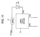
- FIG. 11is a schematic diagram of the circuit in each plug unit.
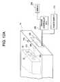
- FIG. 12Ais a perspective view of the rear of the drawer system showing the connection between circuit control boards of the control system.
- FIG. 12Bis a perspective view of the front of the drawer system showing elements on the front of the drawer chassis that are connected to the control system.
- FIGS. 13 and 14are schematic diagrams of a control system according to one embodiment.
- FIG. 15is a block diagram of a control system according to another embodiment.
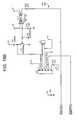
- FIG. 16is a schematic diagram of the master controller interface of the control system shown in FIG. 15 .
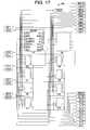
- FIG. 17is a schematic diagram of the channel interface.
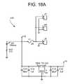
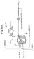
- FIG. 18Ais a schematic diagram of the power interface.
- FIG. 18Bis a schematic diagram of a portion of the front panel jack interface and the door lock interface.
- FIG. 19Ais a schematic diagram of the front panel jack interface and the drawer identification circuitry.
- FIG. 19Bis a schematic diagram of a capacitor network used in the control system shown in FIG. 15 .
- FIG. 19Cis a schematic diagram of the auxiliary interfaces.
- FIGS. 20A and 20Bare schematic diagrams showing connection of a microprocessor board in the control system of FIG. 15 , and showing the drawer sensor interface.
- FIG. 21is a schematic diagram showing integrated circuits useful to provide electrostatic discharge protection.
- FIG. 22is a schematic diagram of another circuit board of the control system shown in FIG. 15 .
- a drawer system 10comprising a drawer body 12 comprising a closed bottom and an open top. Disposed on the bottom surface of the drawer are a plurality of inverted metal channels 20 , each having a squared-off inverted “U” shape. There is at least one, but usually several channels 20 mounted in a drawer 12 .
- the channels 20comprise a horizontal surface 22 , two side vertical surfaces 24 and two feet 26 .
- the jacks 30may be staggered or offset in multiple strings per channel.
- each supporting 50 jacks in two staggered strings of 25 jacksthere may be five channels, each supporting 50 jacks in two staggered strings of 25 jacks.
- the feet 26 of the channels 20attach to the bottom surface of the drawer with, for example, pims welded to the feet 26 .
- Plug units 60fit into the jacks 30 .
- the plug units 60will be described in greater detail hereinafter in conjunction with FIGS. 7-11 .
- the jacks 30are, for example, standard audio jacks each capable of receiving a 1 ⁇ 4 inch audio plug.
- Each jack 30is secured to the channel 20 with a nut on the top of the horizontal surface 22 that threads around the top opening of the jack 20 .
- a variation to the design described aboveis one in which a single structure supports all of the jacks.
- each jackThere are three terminals 32 , 34 and 36 on each jack and therefore three wires 52 , 54 and 56 or connections are made to each jack: a data line or connection for transporting data or control information, a power supply line, and a ground line.
- the data linemay supply power to the memory device of a plug unit (described hereinafter) inserted in a jack, while the dedicated power line is available to supply power to the LED (described hereinafter) of a plug unit in a jack.
- the three contact terminals 32 , 34 and 36 on each jackare inserted into or soldered onto the three wires on the ribbon, cable or printed circuit board panel 40 . All of the jacks 30 in a channel share a common ground. Wires 52 , 54 and 56 are electrically connected between jacks 30 . Another connection method is to solder discrete wires 52 , 54 and 56 between the corresponding three terminals 32 , 34 and 36 of each jack 30 as shown in FIGS. 3 , 5 and 6 . These discrete wires connect from one jack to the next. Still another configuration is to attach three uninsulated wires across the string of jacks similar to that shown in FIG. 4 , but without the circuit board 40 .
- the jacks 30may be formed from an injection molding process creating an integrated structure capable of receiving the plug units, and having electrical connections of any of the variety described above.
- Each plug unit 60comprises an elongated housing 62 .
- An electrically conductive plug member 64 with three contactsextends outward from one end of the housing 62 .
- the plug unit 60is designed to attach or otherwise be associated with an object to be tracked.
- an attachment ring 66is provided on the housing 62 that can be used to attach keys or other objects.
- the keycan be attached to the attachment ring 66 with metal straps, tie wraps or other means.
- a translucent or transparent lens cap 63may be provided for an LED described hereinafter.
- a circuit board 68that is electrically connected to the plug member 64 as explained further hereinafter.
- a memory device 70is mounted on one side of the circuit board 68 (FIG. 9 ).
- the memory device 70is, for example, a DS2405 addressable switch device manufactured and sold by Dallas Semiconductor.
- the DS2405 deviceprovides a means for assigning an electronically readable identification to a particular node or location with additional control capability provided by an open drain N-channel MOSFET that can be remotely switched and sensed via communication over a one-wire bus.
- the DS2405contains a factory-lasered registration number that includes a unique 48-bit serial number which provides a unique electronic identification for the device itself but also is a means to locate and change or read the state of the switch (open or closed) that is associated with it.
- the memory device 70stores a unique identifier to be associated with an object to be tracked.
- One advantage of using the specific type of memory device identified aboveis that it is capable of being electrically accessed for read and write operations with one wire, i.e., the data line, connected to it. On that same side, there is a conductive surface 75 for ground that is soldered to a ground conductive surface/tab of the plug member 64 .
- circuit board 68There is a hole 71 through the circuit board 68 having a conductive surface around the inner surface for coupling power to a power plug tab on the plug member.
- a resistor 72On the opposite side of the circuit board ( FIG. 10 ) a resistor 72 is mounted and a conductive surface 73 is provided for data that is soldered to a data surface/tab of the plug member 64 .
- Extending from the end of the circuit boardis an LED 74 that is connected through the resistor 72 to the memory device 70 .
- the circuit board 68is mounted inside the housing 62 of the plug unit 60 so that the LED 74 is adjacent the lens cap 63 to communicate light outward from the housing 62 .
- FIG. 11shows the schematic connections for the electrical components inside the housing 62 of the plug unit 60 .
- Current-limited (5V) powercomes in to the circuit board and is supplied through an optional resistor 72 to the LED 74 .
- the ground and data linesconnect to corresponding ground and data terminals on the memory device 70 .
- the memory device 70stores a unique identifier to be associated with an object to be tracked and is suitably powered when it receives a signal on its data terminal.
- the LED 74is illuminated when instructed to do so by the master controller.
- the plug member of the plug unitmakes electrical connections to each of the data, power and ground lines in the jack so as to provide access and control over the memory device 70 in a plug unit.
- FIG. 12AThere are many possible configurations for the control system of the drawer system.
- the control systemcomprises two circuit boards: a first board 100 that may be mounted on the rear wall of the drawer chassis, and a second circuit board 300 that may be mounted on the back wall of the drawer 12 .
- the circuit board 100 and the circuit board 300are connected together by a cable or ribbon 500 .
- the circuit board 300connects to the jacks on each channel 20 of the drawer 12 by separate electrical connections 510 , such as RJ11 telephone line-type wires and connectors.
- the circuit board 300interfaces a string of jacks in one or more drawers to the circuit board 100 , which in turns interfaces to a controller, such as a personal computer (PC) 200 , which has an associated display 210 . Power is supplied to the jacks by a power supply 212 .
- PCpersonal computer
- FIG. 12Bshows the front panel of the drawer 12 and the drawer chassis 14 .
- a front panel jack 750On the front of the drawer chassis 14 , there are a front panel jack 750 , a door lock 760 , and a power indicator LED 765 . These elements are electrically connected to the circuit board 100 or 100 ′ as described hereinafter.
- the door lock 760is a solenoid-driven door lock that can be controlled to lock or unlock the drawer.
- the status of the door lock 760(lock/unlock) is provided to the controller.
- the door lock 760may also be locked and unlocked using a key.
- the front panel jack 750is used to allow plug unit identification without having to open the drawer.
- the front panel jack 750is used to allow the user to access the system (e.g., log the user in).
- the identification of the plug unitis obtained and compared against a user database. If a match occurs, the user is logged into the software managed by the master controller (described hereinafter).
- the other use of the front panel jack 750is to create database entries for plug units.
- the usercreates a new database entry for an object (e.g., car keys), and then places the associated plug unit into the front panel jack.
- the software executed by the master controllerthen reads the unique identification of the plug unit, turns on the LED in the plug unit (in part to verify that the LED works), and associates the plug unit with the database entry.
- FIGS. 13 and 14illustrate the circuit boards 100 and 300 according to one embodiment.
- FIGS. 15-22illustrate alternative embodiments of the circuit boards 100 and 300 .
- a master controllere.g., a computer executing a software program and managing a database, accesses the circuit boards and obtains information from the drawer system, which information is used by the software program to manage the database, etc.
- a standard 6-pin interface 215is used to interface to the cable 500 which is coupled to the circuit board 100 .
- An identical connector 217can be used to allow an alternate placement of the interface cable.
- the controlleris coupled through the interface 215 to a drawer branch coupler 230 .
- the drawer branch coupler 230in turn is connected to a control/channel branch coupler 220 .
- the control/channel branch coupler 220is in turn connected to a lock/sensor branch coupler 218 .
- the control/channel branch coupler 220is also connected to a plurality of string branch couplers 240 , 242 , 244 , 246 and 248 .
- Each of the string branch couplers 240 - 248is coupled to a corresponding interface connector 250 - 258 , respectively, that interfaces with two corresponding strings of jacks 30 .
- string branch coupler 240interfaces with strings 1 and 2 in channel 1
- string branch coupler 242interfaces with strings 3 and 4 in channel 2 , etc.
- the couplers 218 , 220 , 230 and 240 - 248are 1-wire couplers, such as the DS2409P coupler made and sold by Dallas Semiconductor, Inc.
- Couplermaintains a common ground level for the entire network and keeps inactive segments powered, as opposed to approaches that switch the ground line. This makes supply of power easier to manage and prevents loss of status of parasitically powered devices. Additional information about the DS2409P 1-wire coupler can be obtained from Dallas Semiconductor, and is well known in the art. The couplers can be connected to each other and to 1-wire memory devices, such as the type included in the plug units 60 .
- Each couplerhas six pins: Pin 1 is ground, pin 2 is the input data/control, pin 3 is main 1-wire data/power, pin 4 is auxiliary 1-wire data/power, pin 5 is control output, and pin 6 is V DD (power).
- a Micro Switch Sense signaldraws close status
- a Door Solenoid (lock) signal lineis coupled to the control output pin 5 .
- a control/communication pathis established between the 1-wire input pin 2 of lock/sensor branch coupler 218 and the auxiliary 1-wire output pin 4 of the control/channel branch coupler 220 .
- a control/communication pathis established between the main 1-wire output pin 3 of control/channel branch coupler 220 and the 1-wire input pin 2 of each of the string branch couplers 240 - 248 .
- a string branch coupler and a channel interfaceare connected as follows.
- the auxiliary 1-wire output pin of string branch coupler 240is coupled to pin 4 of the connector 250 that connects to string 1 of jacks.
- the main 1-wire output pin 3 of the string branch coupler 240is coupled to pin 3 that connects to string 2 of jacks.
- the auxiliary 1-wire output pin 4 of string branch coupler 242is coupled to pin 4 of connector 252 that connects to string 3 of jacks and the main 1-wire output pin 3 of the string branch coupler 242 is coupled to pin 3 of connector 252 that connects to string 4 of jacks.
- the string branch couplers 244 , 246 and 28connect to the interface connectors 254 , 256 and 258 , respectively, in a similar manner.
- the interface connectors 250 - 258are, for example, RJ-11 connectors. Two current limited 5 volt signals are also passed through the connectors 250 - 258 . The current limiting is to keep potential shorts from developing between 5 volts and ground and also to keep from overdriving the LEDs that are housed in the plug units. The ground signal is also passed to all of the channels.
- FIG. 14shows the schematic diagram of the to the circuit board 100 according to one embodiment.
- the interface between the master controller, such as a PC, and between other drawer systemsis provided through headers 260 and 262 .
- Header 260provides a path for 1-wire communications to the master controller 200 .
- Header 262provides a path for 1-wire communications to another drawer system.
- these drawersare considered upstream.
- Drawers connected to header 262are considered downstream.
- data that is meant for downstream drawerswill be passed from header 260 to header 262 via the 1-wire drawer branch coupler 230 described above.
- data from downstream that is meant for the master controllerwill be passed from header 262 to header 260 .
- the header 270may be designed to protrude out the back of the drawer chassis when the board is mounted at the inside rear of the chassis.
- a fuse, F 1is provided to protect the external power supply and the internal circuitry if a power short develops.
- An LED, D 3that also protrudes from the drawer chassis, lights to indicate when the board is powered.
- 5 voltsis used by the board circuitry and is provided through a voltage regulator 272 . This regulator is rated for at least 1 amp operation, for example.
- a heat sinkis generally required on the regulator to help dissipate heat.
- a door lock 760may require 12 volts with a fairly large current draw.
- a MOSFET 274such as a Q1 RFD3055, is used to drive the door lock.
- the controllerdrives the door lock with the door solenoid signal that is accessed through the lock/sensor branch coupler 218 on the other board.
- the signalthen drives an opto-isolator 276 , such as an MCT2E, that in turn drives the MOSFET 274.
- the opto-isolatorprotects the lock/sensor branch coupler 218 in case of MOSFET failure. It also inverts the control logic for the MOSFET 274 which keeps the drawer from unlocking during power-up.
- the signals to/from the door lock 760 and the front panel jack 750are provided by the connector 278 .
- the connector 280is used to provide power to future auxiliary components.
- FIG. 14also shows the 1-wire connections, except for the front panel jack connection, to the connector 215 .
- connector 215provides a path, through a ribbon cable 500 , to the circuit board 300 and ultimately to the jacks 30 located on the channels 20 .
- 5 volts and groundis also passed through the connector 215 to provide power for the plug unit LEDs and a reference ground.
- the couplersroute data/control signals from the controller 200 , and are used to uniquely identify each drawer, the lock/control status mechanism in each drawer, and ultimately each string of jacks in each drawer.
- the controller 200through software executed thereby, accesses the couplers to identify drawers, check drawer open/close status, unlock drawers, scan strings of jacks to plug unit identification, perform FOB identification, etc. Consequently, the controller 200 is able to look up an object, such as a key, in a database, to find its corresponding electronic identifier (ID).
- IDelectronic identifier
- the controller 200then sends a signal through the interface connector 215 into the network of couplers to activate the LED on the plug unit corresponding to the electronic ID in any location that it may reside.
- Plug units and their corresponding objectcan be replaced in any drawer at any location because the controller automatically recognizes the plug unit upon its placement in a jack. Moreover, because the plug units are self-identified by activating their LED when installed in any jack as opposed to in a particular storage location, it is possible to have a mix of different shapes and sizes of storage containers in a facility, all access controlled using the same controller and user interface.
- FIGS. 15-22show another configuration as an alternative to that shown in FIGS. 13 and 14 .
- the circuit board 100 ′ shown in FIG. 15contains an embedded microprocessor board 410 , such as a Rabbit Semiconductor RCM2010, to provide local control of the drawer system. Other microprocessors are suitable.
- the embedded processorutilizes its digital inputs and outputs to communicate with the various interface circuitry.
- the power interface 420provides an interface to AC/DC power supply 212 .
- the front panel jack interface 430interfaces with the front panel jack 750 .
- the door lock interface 440interfaces with the door lock 760 .
- the master interfaceis for example, an RS232 interface that couples to a DB9-RJ12 interface 730 , which in turn is connected to the master controller (PC) 200 and to a next drawer 740 in a chain (if there are multiple drawers in the system).
- the drawer sensor interface 460interfaces with the drawer sensor 770 that is positioned in the drawer chassis in a variety locations, one of which is shown in FIG. 12 B.
- the channel interface 480interfaces with the circuit board 300 ′, which in turn couples to the jacks 30 on the channels 20 .
- the circuit board 100 ′may be designed such that when it is mounted, the RS232 connectors (such as RJ12), power connector, and power indicator (such as an LED) extrude through the chassis. This is to provide access from the outside of the chassis with the connectors mounted directly to the board.
- the circuit board 300 ′provides an additional connector conversion and current limiting between the circuit board 300 ′ and the channels 20 of jacks 30 .
- FIGS. 16-21The master interface 450 between embedded microprocessor board 410 and the master controller 200 , and between the board 410 and the next drawer 740 in the chain, is shown in FIG. 16 .
- Header J 12provides a path for RS232 communications to the master controller 700 .
- Header J 13provides a path for RS232 communications to another drawer system.
- Drawers connected to header J 13are considered downstream. Generally, data that is meant for downstream drawers will be passed from header J 12 to header J 13 via the embedded microprocessor 410 .
- data from downstreamthat is meant for the master controller will be passed from J 13 to J 12 .
- the data from a downstream drawermay first be manipulated by the current drawer system. For example, if there is a global request by the master controller to get drawer IDs, the current drawer system may pass the request downstream. When the response from downstream is returned, the current drawer system may append its ID to the message and send it upstream.
- the RS232 signalsare converted to/from standard digital 5 volt signals using a RS232 interface IC U 15 such as the MAX232.
- Interface IC U 15is used to convert the transmit and receive signals while interface IC U 16 is used to convert the request to send (RTS) and clear to send (CTS) signals.
- RTSrequest to send
- CTSclear to send
- the 5 volt signalsare passed to the serial port pins of the microprocessor 410 .
- FIG. 17shows the channel interface 480 between the microprocessor 410 and the data lines that will eventually reach the channel jacks, and ultimately a plug unit.
- the 1-wire communication protocolis followed as specified by Dallas Semiconductor, Inc.
- One method of providing 1-wire communications from an embedded microprocessoris to utilize an interface IC, such as the DS1481 interface, manufactured by Dallas Semiconductor, Inc.
- the DS1481is a dedicated 1-wire timing generator and is normally used in conjunction with a parallel port controller to provide the necessary interface between 1-wire devices, such as the 1-wire memory device and the host processor.
- This ICis controlled by the microprocessor through the ENI, D/CLK, and RES lines.
- the microprocessorcan get the IC status through the O1/BSY1 line.
- the I/O lineprovides the 1-wire line that can be electrically connected to 1-wire devices, such as the plug unit.
- the protocol for these linescan be found datasheets for the IC published by Dallas Semiconductor.
- U 3 through U 12there are ten DS1481 ICs, designated U 3 through U 12 , used to communicate to plug units in each of the ten strings or subsets of receptacles, two strings per channel. This isolates the strings (subsets) such that if one string (subset) malfunctions, the other strings are not affected.
- this novel approach of separate string controlprovides substantially simultaneous processing of the strings (subsets) of receptacles.
- FIG. 18Ashows the power interface 420 and FIG. 18B shows the door lock interface 440 and a portion of the front panel jack interface 430 .
- twelve volt DC poweris obtained through the connector J 5 .
- This poweris output through the connectors J 4 and J 4 A for future auxiliary power.
- the connector J 5is designed to protrude outward from the back of the drawer chassis when the board is mounted at the inside rear of the chassis.
- a fuse, F 1is provided to protect the external power supply and the internal circuitry if a power short develops.
- the power LED indicator 765(corresponding to D 3 in FIG. 18A ) also protrudes from the front of drawer chassis as shown in FIG. 12 B and lights to indicate when the board is powered.
- 5 voltsis also required by the board circuitry. This is provided through a voltage regulator, 7805 . This regulator should be rated for at least 1 amp operation. A heat sink is generally required on the regulator to help dissipate heat.
- the door lock interface 440 and part of the front panel jack interface 430is shown.
- the door lock 760may require 12 volts with a fairly large current draw.
- a MOSFETsuch as Q1 RFD3055, is used to drive the door lock 760 .
- the microprocessor 710drives the door lock with the door solenoid signal. This signal then drives an opto-isolator U 17 , such as a MCT2E, that in turn drives the MOSFET.
- the opto-isolator U 17protects the microprocessor 410 in case of MOSFET failure. It also inverts the control logic for the MOSFET which keeps the drawer from unlocking during power-up.
- the signals to/from the door lock and the front panel jackare provided by the J 11 connector.
- the J 6 connectoris used to provide power to future auxiliary components.
- the front panel jack interface 430comprises a DS1481 U 1 .
- this ICprovides an interface between the microprocessor and 1-wire devices.
- This ICis connected to the front panel jack and also to an ID chip, such as the DS2401P U 2 .
- the ID chip U 2provides an ID that is unique to the drawer system.
- FIG. 19Billustrates a network of bypass capacitors useful for noise protection on the power supply. The capacitor network is connected near the power connections for the integrated circuits.
- FIG. 19Cillustrates the auxiliary interfaces 490 .
- the microprocessor 410provides local control of the drawer system.
- the microprocessor 410receives requests from the master controller 700 , performs the function, and returns the results to the master controller 700 . Examples include scanning for plug units, testing for drawer status (opened/closed), unlocking or locking the drawer, returning its ID, checking for presence of a plug unit in the front panel jack, and lighting or unlighting plug units.
- the microprocessor 410is located on a separate printed circuit board that connects to the circuit board 100 ′ via two connectors J 1 and J 2 shown in FIGS. 20A and 20B . These connectors pass power to the microprocessor board and provide all input and output signals required by the microprocessor 410 to properly control the drawer system.
- An additional item shown in FIG. 20Bis the drawer sensor interface 460 (connector J 3 ) for the drawer sensor 770 ( FIG. 12A ) that determines if the drawer is opened or closed.
- Electrostatic discharge protection for all 1-wire interfacesis provided by ICs U 13 and U 14 , such as a PACDN 006 , as shown in FIG. 21 .
- This figurealso shows the 1-wire connections, except for the front panel jack connection, to the connector J 10 .
- This connectorprovides a path, through a ribbon cable, to the circuit board 300 ′ and ultimately to the jacks located on the channels.
- 5 volts and groundis also passed through the connector to provide power for the plug unit LEDs and a reference ground.
- FIG. 22A schematic of the circuit board 300 ′ located at the back of the storage drawer is shown in FIG. 22 .
- This boardreceives 1-wire data lines from the circuit board through the connector J 10 (FIG. 21 ). It also receives 5 volts and a ground signal. These signals are then passed onto connectors J 5 through J 9 (which may be RJ12 connectors for example) that are connected to the channels. The 5-volt signal is also passed to the channels, through resistors R 5 through R 14 . These resistors restrict the maximum current that can flow through the lines. This is to keep potential shorts from developing between 5 volts and ground and also to keep from overdriving the LEDs that are housed in the plug units. The ground signal is also passed to all of the channels. Finally, an LED D 1 is provided to indicate that power is being applied to the board.
Landscapes
- Physics & Mathematics (AREA)
- General Physics & Mathematics (AREA)
- Engineering & Computer Science (AREA)
- Theoretical Computer Science (AREA)
- Details Of Connecting Devices For Male And Female Coupling (AREA)
Abstract
Description
Claims (32)
Priority Applications (1)
| Application Number | Priority Date | Filing Date | Title |
|---|---|---|---|
| US10/059,043US6867695B2 (en) | 2001-02-01 | 2002-01-30 | Object storage and tracking system, an object tracking unit and a container for object tracking units |
Applications Claiming Priority (2)
| Application Number | Priority Date | Filing Date | Title |
|---|---|---|---|
| US26582401P | 2001-02-01 | 2001-02-01 | |
| US10/059,043US6867695B2 (en) | 2001-02-01 | 2002-01-30 | Object storage and tracking system, an object tracking unit and a container for object tracking units |
Publications (2)
| Publication Number | Publication Date |
|---|---|
| US20020113706A1 US20020113706A1 (en) | 2002-08-22 |
| US6867695B2true US6867695B2 (en) | 2005-03-15 |
Family
ID=23012020
Family Applications (1)
| Application Number | Title | Priority Date | Filing Date |
|---|---|---|---|
| US10/059,043Expired - LifetimeUS6867695B2 (en) | 2001-02-01 | 2002-01-30 | Object storage and tracking system, an object tracking unit and a container for object tracking units |
Country Status (3)
| Country | Link |
|---|---|
| US (1) | US6867695B2 (en) |
| CA (1) | CA2437171A1 (en) |
| WO (1) | WO2002061654A1 (en) |
Cited By (12)
| Publication number | Priority date | Publication date | Assignee | Title |
|---|---|---|---|---|
| US20040160304A1 (en)* | 2002-04-30 | 2004-08-19 | General Electric Company | Managing access to physical assets |
| US20050242666A1 (en)* | 2003-09-25 | 2005-11-03 | Rainer Huscher | Device for acquiring signals from sensors installed in a motor vehicle |
| US7116228B1 (en)* | 2001-02-20 | 2006-10-03 | Key Control Holding, Inc. | Asset management system |
| US20070241898A1 (en)* | 2004-12-14 | 2007-10-18 | Declan Comerford | Security System |
| US20080252415A1 (en)* | 2007-04-12 | 2008-10-16 | Larson Wayne F | Restricted range lockbox, access device and methods |
| US20110012735A1 (en)* | 2009-06-15 | 2011-01-20 | Jerry Kestenbaum | Item storage and tracking system |
| US20110115610A1 (en)* | 2008-07-09 | 2011-05-19 | Thomas Fergus Hughes | Laboratory sample archiving apparatus and method |
| US8194045B1 (en) | 2005-01-27 | 2012-06-05 | Singleton Technology, Llc | Transaction automation and archival system using electronic contract disclosure units |
| US8228299B1 (en) | 2005-01-27 | 2012-07-24 | Singleton Technology, Llc | Transaction automation and archival system using electronic contract and disclosure units |
| US20130154834A1 (en)* | 2011-12-19 | 2013-06-20 | Tyco Safety Products Canada Ltd. | Cabinet with tamper detection system and method |
| US20180276929A1 (en)* | 2017-03-21 | 2018-09-27 | Bobby JAIN | Key fob for a key management system |
| US11398122B2 (en) | 2017-04-28 | 2022-07-26 | 1 Micro, LLC | Passenger authentication system for a transportation service vehicle |
Families Citing this family (11)
| Publication number | Priority date | Publication date | Assignee | Title |
|---|---|---|---|---|
| US7123127B2 (en)* | 2003-01-31 | 2006-10-17 | General Electric Company | System for managing physical assets |
| US7042334B2 (en)* | 2003-01-31 | 2006-05-09 | General Electric Company | Methods for managing access to physical assets |
| US6731211B1 (en)* | 2002-11-20 | 2004-05-04 | Micheal A. King | Key control tag |
| US20100250309A1 (en)* | 2007-12-04 | 2010-09-30 | Ford Global Technologies, Llc | Asset management system and method for an automotive vehicle |
| US8193924B2 (en)* | 2009-04-02 | 2012-06-05 | Ford Global Technologies, Llc | Automotive vehicle and asset management system therefor |
| US8193923B2 (en) | 2009-04-02 | 2012-06-05 | Ford Global Technologies, Llc | Automotive vehicle and asset management system therefor |
| US9633496B2 (en) | 2014-01-09 | 2017-04-25 | Ford Global Technologies, Llc | Vehicle contents inventory system |
| US9255810B2 (en) | 2014-01-09 | 2016-02-09 | Ford Global Technologies, Llc | Vehicle contents inventory system interface |
| US10062227B2 (en) | 2014-01-09 | 2018-08-28 | Ford Global Technologies, Llc | Contents inventory tracking system and protocol |
| US9836717B2 (en) | 2014-01-09 | 2017-12-05 | Ford Global Technologies, Llc | Inventory tracking system classification strategy |
| US10210068B2 (en)* | 2015-04-13 | 2019-02-19 | Leviton Manufacturing Co., Inc. | Device topology definition system |
Citations (21)
| Publication number | Priority date | Publication date | Assignee | Title |
|---|---|---|---|---|
| US3975722A (en) | 1975-02-03 | 1976-08-17 | Shaul Adler | Protective alarm system |
| US4205328A (en) | 1977-01-20 | 1980-05-27 | Motohiro Gotanda | Apparatus for controlling a power source for an electrical alarm or indicator |
| US4549170A (en) | 1982-05-17 | 1985-10-22 | Serres Bernard M | System for managing a panel of objects such as keys |
| US4595922A (en) | 1984-12-10 | 1986-06-17 | Cobb Richard G | Method and apparatus for monitoring keys and other articles |
| US4635053A (en) | 1983-09-06 | 1987-01-06 | Banks Edward J K | Apparatus for supervising access to individual items |
| US4661806A (en) | 1985-05-10 | 1987-04-28 | Peters Gilbert A | Computer controlled key management system |
| US4673915A (en) | 1985-12-12 | 1987-06-16 | Cobb Richard G | Key storage and monitoring system |
| US5038023A (en) | 1989-06-28 | 1991-08-06 | C. Itoh Information Systems Development, Inc. | System for storing and monitoring bar coded articles such as keys in a drawer |
| US5038123A (en) | 1989-12-14 | 1991-08-06 | General Motors Corporation | Flat electromagnetic relay |
| WO1995004324A1 (en) | 1993-07-29 | 1995-02-09 | Morse Watchmans, Inc. | System and device for storing objects |
| WO1995012858A1 (en) | 1993-11-04 | 1995-05-11 | The General Hospital Corporation | Managing an inventory of devices |
| WO1997009687A1 (en)* | 1995-09-08 | 1997-03-13 | Key-Trak, Inc. | Inventoriable-object control and tracking system |
| US5946278A (en) | 1996-09-09 | 1999-08-31 | Tower; Robert P. | Storage and selection system for audio, visual, and information storage media |
| US6075441A (en) | 1996-09-05 | 2000-06-13 | Key-Trak, Inc. | Inventoriable-object control and tracking system |
| US6195005B1 (en) | 1998-09-11 | 2001-02-27 | Key-Trak, Inc. | Object carriers for an object control and tracking system |
| US6204764B1 (en) | 1998-09-11 | 2001-03-20 | Key-Trak, Inc. | Object tracking system with non-contact object detection and identification |
| US6232876B1 (en) | 1998-09-11 | 2001-05-15 | Key-Trak, Inc. | Mobile object tracking system |
| USD444331S1 (en) | 1996-09-05 | 2001-07-03 | Key-Trak, Inc. | Drawer panel |
| US6262664B1 (en) | 1998-09-11 | 2001-07-17 | Key-Trak, Inc. | Tamper detection prevention for an object control and tracking system |
| USD456852S1 (en) | 2000-03-31 | 2002-05-07 | Key-Trak, Inc. | Key tag |
| US6427913B1 (en) | 1998-09-11 | 2002-08-06 | Key-Trak, Inc. | Object control and tracking system with zonal transition detection |
- 2002
- 2002-01-30CACA002437171Apatent/CA2437171A1/ennot_activeAbandoned
- 2002-01-30WOPCT/US2002/002429patent/WO2002061654A1/ennot_activeApplication Discontinuation
- 2002-01-30USUS10/059,043patent/US6867695B2/ennot_activeExpired - Lifetime
Patent Citations (37)
| Publication number | Priority date | Publication date | Assignee | Title |
|---|---|---|---|---|
| US3975722A (en) | 1975-02-03 | 1976-08-17 | Shaul Adler | Protective alarm system |
| US4205328A (en) | 1977-01-20 | 1980-05-27 | Motohiro Gotanda | Apparatus for controlling a power source for an electrical alarm or indicator |
| US4549170A (en) | 1982-05-17 | 1985-10-22 | Serres Bernard M | System for managing a panel of objects such as keys |
| US4635053A (en) | 1983-09-06 | 1987-01-06 | Banks Edward J K | Apparatus for supervising access to individual items |
| US4595922A (en) | 1984-12-10 | 1986-06-17 | Cobb Richard G | Method and apparatus for monitoring keys and other articles |
| US4661806A (en) | 1985-05-10 | 1987-04-28 | Peters Gilbert A | Computer controlled key management system |
| US4673915A (en) | 1985-12-12 | 1987-06-16 | Cobb Richard G | Key storage and monitoring system |
| US5038023A (en) | 1989-06-28 | 1991-08-06 | C. Itoh Information Systems Development, Inc. | System for storing and monitoring bar coded articles such as keys in a drawer |
| US5038123A (en) | 1989-12-14 | 1991-08-06 | General Motors Corporation | Flat electromagnetic relay |
| WO1995004324A1 (en) | 1993-07-29 | 1995-02-09 | Morse Watchmans, Inc. | System and device for storing objects |
| US6131808A (en) | 1993-07-29 | 2000-10-17 | Morse Watchmans Inc. | System and device for storing objects |
| WO1995012858A1 (en) | 1993-11-04 | 1995-05-11 | The General Hospital Corporation | Managing an inventory of devices |
| WO1997009687A1 (en)* | 1995-09-08 | 1997-03-13 | Key-Trak, Inc. | Inventoriable-object control and tracking system |
| US5801628A (en) | 1995-09-08 | 1998-09-01 | Key-Trak, Inc. | Inventoriable-object control and tracking system |
| US6075441A (en) | 1996-09-05 | 2000-06-13 | Key-Trak, Inc. | Inventoriable-object control and tracking system |
| US6317044B1 (en) | 1996-09-05 | 2001-11-13 | Key-Track, Inc. | Inventoriable object control and tracking system |
| USD444331S1 (en) | 1996-09-05 | 2001-07-03 | Key-Trak, Inc. | Drawer panel |
| US5946278A (en) | 1996-09-09 | 1999-08-31 | Tower; Robert P. | Storage and selection system for audio, visual, and information storage media |
| US6232876B1 (en) | 1998-09-11 | 2001-05-15 | Key-Trak, Inc. | Mobile object tracking system |
| US20020044055A1 (en) | 1998-09-11 | 2002-04-18 | Key-Trak, Inc. | Object carriers for an object control and tracking system |
| US6204764B1 (en) | 1998-09-11 | 2001-03-20 | Key-Trak, Inc. | Object tracking system with non-contact object detection and identification |
| US20010006368A1 (en) | 1998-09-11 | 2001-07-05 | Key-Trak, Inc. | Object tracking system with non-contact object detection and identification |
| US6262664B1 (en) | 1998-09-11 | 2001-07-17 | Key-Trak, Inc. | Tamper detection prevention for an object control and tracking system |
| US20010009397A1 (en) | 1998-09-11 | 2001-07-26 | Key-Trak, Inc. | Object carriers for an object control and tracking system |
| US20010022552A1 (en) | 1998-09-11 | 2001-09-20 | Key-Trak, Inc. | Tamper detection and prevention for an object control and tracking system |
| US6195005B1 (en) | 1998-09-11 | 2001-02-27 | Key-Trak, Inc. | Object carriers for an object control and tracking system |
| US20020014961A1 (en) | 1998-09-11 | 2002-02-07 | Key-Trak, Inc. | Mobile object tracking system |
| US20010004235A1 (en) | 1998-09-11 | 2001-06-21 | Key-Trak, Inc. | Mobile object tracking system |
| US20030052782A1 (en) | 1998-09-11 | 2003-03-20 | Key-Trak, Inc. | Tamper detection and prevention for an object control and tracking system |
| US6392543B2 (en) | 1998-09-11 | 2002-05-21 | Key-Trak, Inc. | Mobile object tracking system |
| US6407665B2 (en) | 1998-09-11 | 2002-06-18 | Key-Trak, Inc. | Object tracking system with non-contact object detection and identification |
| US20020075154A1 (en) | 1998-09-11 | 2002-06-20 | Key-Trak, Inc. | Mobile object tracking system |
| US6424260B2 (en) | 1998-09-11 | 2002-07-23 | Key-Trak, Inc. | Mobile object tracking system |
| US6427913B1 (en) | 1998-09-11 | 2002-08-06 | Key-Trak, Inc. | Object control and tracking system with zonal transition detection |
| US20020145520A1 (en) | 1998-09-11 | 2002-10-10 | Key-Trak, Inc. | Object tracking system with non-contact object detection and identification |
| US6501379B2 (en) | 1998-09-11 | 2002-12-31 | Key-Trak, Inc. | Object carriers for an object control and tracking system |
| USD456852S1 (en) | 2000-03-31 | 2002-05-07 | Key-Trak, Inc. | Key tag |
Non-Patent Citations (5)
| Title |
|---|
| "50 Ways to Touch Memory", Third Edition, Aug. 1994, Dallas Semiconductor. |
| "DS2407 Dual Addressable Switch Plus Memory 1K-Bit Memory", Data Sheet, Copyright 1995, Dallas Semiconductor, pp. 1-31. |
| Dallas Semiconductor Corporation, "Application Note 104: Minimalist Temperature Control Demo", pp. 1901-1904, at http://web.archive.org/web19961102012829/www.dalsemi.com/DocControl/PDFs/app104.pdf (1995). |
| Dallas Semiconductor Corporation, "Application Note 106: Complex MicroLANs", pp. 1905-1919, at http://web.archive.org/web/19961102012933/www.dalsemi.com/DocControl/PDFs/app106.pdf (1995). |
| Dan Awtrey, "MicroLAN Design Guide", Copyright 1998, Dallas Semiconductor. |
Cited By (28)
| Publication number | Priority date | Publication date | Assignee | Title |
|---|---|---|---|---|
| US7116228B1 (en)* | 2001-02-20 | 2006-10-03 | Key Control Holding, Inc. | Asset management system |
| US20040160304A1 (en)* | 2002-04-30 | 2004-08-19 | General Electric Company | Managing access to physical assets |
| US7061367B2 (en)* | 2002-04-30 | 2006-06-13 | General Electric Company | Managing access to physical assets |
| US20050242666A1 (en)* | 2003-09-25 | 2005-11-03 | Rainer Huscher | Device for acquiring signals from sensors installed in a motor vehicle |
| US8358206B2 (en)* | 2003-09-25 | 2013-01-22 | Nexans | Device for acquiring signals from sensors installed in a motor vehicle |
| US20070241898A1 (en)* | 2004-12-14 | 2007-10-18 | Declan Comerford | Security System |
| US7760091B2 (en)* | 2004-12-14 | 2010-07-20 | Declan Comerford | Security system |
| US9916018B1 (en) | 2005-01-27 | 2018-03-13 | Reynolds & Reynolds Holdings, Inc. | Transaction automation and archival system using electronic contract disclosure units |
| US10133385B1 (en) | 2005-01-27 | 2018-11-20 | Reynolds & Reynolds Holdings, Inc. | Transaction automation and archival system using electronic contract disclosure units |
| US8194045B1 (en) | 2005-01-27 | 2012-06-05 | Singleton Technology, Llc | Transaction automation and archival system using electronic contract disclosure units |
| US8228299B1 (en) | 2005-01-27 | 2012-07-24 | Singleton Technology, Llc | Transaction automation and archival system using electronic contract and disclosure units |
| US8933904B2 (en) | 2005-01-27 | 2015-01-13 | Reynolds & Reynolds Holdings, Inc. | Transaction automation and archival system using electronic contract disclosure units |
| US9235276B1 (en) | 2005-01-27 | 2016-01-12 | Reynolds & Reynolds Holding, Inc. | Transaction automation and archival system using electronic contract disclosure units |
| US8531424B1 (en) | 2005-01-27 | 2013-09-10 | Reynolds & Reynolds Holdings, Inc. | Transaction automation and archival system using electronic contract disclosure units |
| US8547356B2 (en) | 2005-01-27 | 2013-10-01 | Reynolds & Reynolds Holdings, Inc. | Transaction automation and archival system using electronic contract disclosure units |
| US9081423B2 (en) | 2005-01-27 | 2015-07-14 | Reynolds & Reynolds Holdings, Inc. | Transaction automation and archival system using electrode contract disclosure units |
| US8854330B1 (en) | 2005-01-27 | 2014-10-07 | Reynolds & Reynolds Holdings, Inc. | Transaction automation and archival system using electronic contract disclosure units |
| US9670694B2 (en) | 2007-04-12 | 2017-06-06 | Utc Fire & Security Americas Corporation, Inc. | Restricted range lockbox, access device and methods |
| US20080252415A1 (en)* | 2007-04-12 | 2008-10-16 | Larson Wayne F | Restricted range lockbox, access device and methods |
| US8952787B2 (en)* | 2008-07-09 | 2015-02-10 | Thomas Fergus Hughes | Laboratory sample archiving apparatus and method |
| US20110115610A1 (en)* | 2008-07-09 | 2011-05-19 | Thomas Fergus Hughes | Laboratory sample archiving apparatus and method |
| US8610574B2 (en) | 2009-06-15 | 2013-12-17 | Gerald Isaac Kestenbaum | Item storage and tracking system |
| US20110012735A1 (en)* | 2009-06-15 | 2011-01-20 | Jerry Kestenbaum | Item storage and tracking system |
| US20130154834A1 (en)* | 2011-12-19 | 2013-06-20 | Tyco Safety Products Canada Ltd. | Cabinet with tamper detection system and method |
| US20180276929A1 (en)* | 2017-03-21 | 2018-09-27 | Bobby JAIN | Key fob for a key management system |
| US10748363B2 (en)* | 2017-03-21 | 2020-08-18 | Marcon International Inc | Key fob for a key management system |
| US11398122B2 (en) | 2017-04-28 | 2022-07-26 | 1 Micro, LLC | Passenger authentication system for a transportation service vehicle |
| US12283146B2 (en) | 2017-04-28 | 2025-04-22 | 1Micro, Llc | Methods and apparatus for accessing secured physical assets at a facility utilized for maintenance and management |
Also Published As
| Publication number | Publication date |
|---|---|
| US20020113706A1 (en) | 2002-08-22 |
| WO2002061654A1 (en) | 2002-08-08 |
| CA2437171A1 (en) | 2002-08-08 |
Similar Documents
| Publication | Publication Date | Title |
|---|---|---|
| US6867695B2 (en) | Object storage and tracking system, an object tracking unit and a container for object tracking units | |
| US5570002A (en) | Universal power-supply connection system for multiple electronic devices | |
| US6054846A (en) | Universal power-supply connection system for multiple electronic devices, and devices for use therewith | |
| CN102742293B (en) | Automatic tracing cable connects and identifies the correlation technique of the system of work area equipment, apparatus and method and operation communication network | |
| US9812825B2 (en) | Ethernet device | |
| US7275970B2 (en) | Plug error insertion prevention systems, plugs, plug insertion sections, plug control programs, contactless identification tag control programs, and plug insertion section control programs | |
| US9113236B2 (en) | Physical layer management using RFID modules and common mode signaling | |
| US20080186130A1 (en) | Key management system | |
| WO2009108177A2 (en) | Intelligent mpo-to-mpo patch panels having connectivity tracking capabilities and related methods | |
| US6501659B1 (en) | Method and system for identifying an industrial personal computer in a rack | |
| US20070075586A1 (en) | Ethernet powered device with an internaly controlled auxiliary power ouput | |
| US5404268A (en) | Interface allowing normal or inverted insertion of data communications card | |
| US20080141056A1 (en) | Asset, PoE and power supply, stack management controller | |
| US4891636A (en) | Electronic keylock system | |
| US7075769B2 (en) | Next connect electrical receptacle assembly | |
| US7623032B2 (en) | Object controlled access and inventory system | |
| US4903230A (en) | Remote terminal address and baud rate selection | |
| CN211062135U (en) | Storing cabinet | |
| CN217008314U (en) | Intelligent key management cabinet | |
| US20070108299A1 (en) | Electrical device with stored data | |
| US20040004130A1 (en) | Identification module for mobile platform | |
| CN200986663Y (en) | Programable controller system | |
| CN209590842U (en) | A kind of monitoring system server based on network security | |
| US11257310B2 (en) | Function module for an electronic access control | |
| KR200348874Y1 (en) | Locker system with rf reader |
Legal Events
| Date | Code | Title | Description |
|---|---|---|---|
| AS | Assignment | Owner name:KEY REGISTER SYSTEMS, INC., CALIFORNIA Free format text:ASSIGNMENT OF ASSIGNORS INTEREST;ASSIGNORS:PRADO, RONALD J.;COLLINS, THOMAS R.;REEL/FRAME:014300/0441 Effective date:20030718 | |
| AS | Assignment | Owner name:KEY-TRAK, INC., TEXAS Free format text:ASSIGNMENT OF ASSIGNORS INTEREST;ASSIGNOR:KEY REGISTER SYSTEMS, INC.;REEL/FRAME:015132/0243 Effective date:20040908 | |
| STCF | Information on status: patent grant | Free format text:PATENTED CASE | |
| AS | Assignment | Owner name:KEY CONTROL HOLDINGS, INC., A DELAWARE CORPORATION Free format text:CHANGE OF NAME;ASSIGNOR:KEY-TRAK, INC., A FLORIDA CORPORATION;REEL/FRAME:018645/0362 Effective date:20041209 | |
| FPAY | Fee payment | Year of fee payment:4 | |
| AS | Assignment | Owner name:DEUTSCHE BANK AG NEW YORK BRANCH, AS COLLATERAL AG Free format text:SECURITY INTEREST;ASSIGNOR:KEY CONTROL HOLDING, INC.;REEL/FRAME:024286/0176 Effective date:20100421 | |
| FPAY | Fee payment | Year of fee payment:8 | |
| AS | Assignment | Owner name:KEY CONTROL HOLDING, INC., TEXAS Free format text:RELEASE BY SECURED PARTY;ASSIGNOR:DEUTSCHE BANK AG NEW YORK BRANCH;REEL/FRAME:037719/0195 Effective date:20160210 | |
| FPAY | Fee payment | Year of fee payment:12 |