US6866822B1 - Gimbaled bladder actuator for use with test strips - Google Patents
Gimbaled bladder actuator for use with test stripsDownload PDFInfo
- Publication number
- US6866822B1 US6866822B1US09/637,504US63750400AUS6866822B1US 6866822 B1US6866822 B1US 6866822B1US 63750400 AUS63750400 AUS 63750400AUS 6866822 B1US6866822 B1US 6866822B1
- Authority
- US
- United States
- Prior art keywords
- bladder
- gimbaled
- actuator
- meter
- compression pad
- Prior art date
- Legal status (The legal status is an assumption and is not a legal conclusion. Google has not performed a legal analysis and makes no representation as to the accuracy of the status listed.)
- Expired - Lifetime, expires
Links
Images


Classifications
- B—PERFORMING OPERATIONS; TRANSPORTING
- B01—PHYSICAL OR CHEMICAL PROCESSES OR APPARATUS IN GENERAL
- B01L—CHEMICAL OR PHYSICAL LABORATORY APPARATUS FOR GENERAL USE
- B01L3/00—Containers or dishes for laboratory use, e.g. laboratory glassware; Droppers
- B—PERFORMING OPERATIONS; TRANSPORTING
- B01—PHYSICAL OR CHEMICAL PROCESSES OR APPARATUS IN GENERAL
- B01L—CHEMICAL OR PHYSICAL LABORATORY APPARATUS FOR GENERAL USE
- B01L3/00—Containers or dishes for laboratory use, e.g. laboratory glassware; Droppers
- B01L3/50—Containers for the purpose of retaining a material to be analysed, e.g. test tubes
- B01L3/502—Containers for the purpose of retaining a material to be analysed, e.g. test tubes with fluid transport, e.g. in multi-compartment structures
- B01L3/5027—Containers for the purpose of retaining a material to be analysed, e.g. test tubes with fluid transport, e.g. in multi-compartment structures by integrated microfluidic structures, i.e. dimensions of channels and chambers are such that surface tension forces are important, e.g. lab-on-a-chip
- B01L3/50273—Containers for the purpose of retaining a material to be analysed, e.g. test tubes with fluid transport, e.g. in multi-compartment structures by integrated microfluidic structures, i.e. dimensions of channels and chambers are such that surface tension forces are important, e.g. lab-on-a-chip characterised by the means or forces applied to move the fluids
- B—PERFORMING OPERATIONS; TRANSPORTING
- B01—PHYSICAL OR CHEMICAL PROCESSES OR APPARATUS IN GENERAL
- B01L—CHEMICAL OR PHYSICAL LABORATORY APPARATUS FOR GENERAL USE
- B01L9/00—Supporting devices; Holding devices
- B01L9/52—Supports specially adapted for flat sample carriers, e.g. for plates, slides, chips
- B—PERFORMING OPERATIONS; TRANSPORTING
- B01—PHYSICAL OR CHEMICAL PROCESSES OR APPARATUS IN GENERAL
- B01L—CHEMICAL OR PHYSICAL LABORATORY APPARATUS FOR GENERAL USE
- B01L2300/00—Additional constructional details
- B01L2300/08—Geometry, shape and general structure
- B01L2300/0809—Geometry, shape and general structure rectangular shaped
- B01L2300/0825—Test strips
- B—PERFORMING OPERATIONS; TRANSPORTING
- B01—PHYSICAL OR CHEMICAL PROCESSES OR APPARATUS IN GENERAL
- B01L—CHEMICAL OR PHYSICAL LABORATORY APPARATUS FOR GENERAL USE
- B01L2300/00—Additional constructional details
- B01L2300/08—Geometry, shape and general structure
- B01L2300/0861—Configuration of multiple channels and/or chambers in a single devices
- B01L2300/0864—Configuration of multiple channels and/or chambers in a single devices comprising only one inlet and multiple receiving wells, e.g. for separation, splitting
- B—PERFORMING OPERATIONS; TRANSPORTING
- B01—PHYSICAL OR CHEMICAL PROCESSES OR APPARATUS IN GENERAL
- B01L—CHEMICAL OR PHYSICAL LABORATORY APPARATUS FOR GENERAL USE
- B01L2400/00—Moving or stopping fluids
- B01L2400/04—Moving fluids with specific forces or mechanical means
- B01L2400/0475—Moving fluids with specific forces or mechanical means specific mechanical means and fluid pressure
- B01L2400/0481—Moving fluids with specific forces or mechanical means specific mechanical means and fluid pressure squeezing of channels or chambers
- B—PERFORMING OPERATIONS; TRANSPORTING
- B01—PHYSICAL OR CHEMICAL PROCESSES OR APPARATUS IN GENERAL
- B01L—CHEMICAL OR PHYSICAL LABORATORY APPARATUS FOR GENERAL USE
- B01L2400/00—Moving or stopping fluids
- B01L2400/06—Valves, specific forms thereof
- B01L2400/0688—Valves, specific forms thereof surface tension valves, capillary stop, capillary break
- Y—GENERAL TAGGING OF NEW TECHNOLOGICAL DEVELOPMENTS; GENERAL TAGGING OF CROSS-SECTIONAL TECHNOLOGIES SPANNING OVER SEVERAL SECTIONS OF THE IPC; TECHNICAL SUBJECTS COVERED BY FORMER USPC CROSS-REFERENCE ART COLLECTIONS [XRACs] AND DIGESTS
- Y10—TECHNICAL SUBJECTS COVERED BY FORMER USPC
- Y10T—TECHNICAL SUBJECTS COVERED BY FORMER US CLASSIFICATION
- Y10T436/00—Chemistry: analytical and immunological testing
- Y10T436/11—Automated chemical analysis
- Y10T436/113332—Automated chemical analysis with conveyance of sample along a test line in a container or rack
- Y10T436/114165—Automated chemical analysis with conveyance of sample along a test line in a container or rack with step of insertion or removal from test line
Definitions
- the field of this inventionis fluidic medical diagnostic devices for measuring the concentration of an analyte in or a property of a biological fluid.
- a variety of medical diagnostic proceduresinvolve tests on biological fluids, such as blood, urine, or saliva, and are based on a change in a physical characteristic of such a fluid or an element of the fluid, such as blood serum.
- the characteristiccan be an electrical, magnetic, fluidic, or optical property.
- these proceduresmay make use of a transparent or translucent device to contain the biological fluid and a reagent.
- a change in light absorption of the fluidcan be related to an analyte H concentration in, or property of, the fluid.
- fluidis introduced into the device at one location but analyzed at another.
- movement of the introduced fluid from the introduction location to the measurement locationis necessary.
- these devicesrequire a means for moving fluid from the introduction site to the measurement site.
- One type of devicerelies on capillary action to move fluid through the device, where the fluid paths through the device are dimensioned to provide for this capillary action.
- Other designsinclude those intended for use with gravity, those intended for use with injection of the sample under pressure, and the like.
- fluidis moved through the device from the point of introduction by negative pressure, where the negative pressure is typically provided by a compressible bladder.
- negative pressuretypically provided by a compressible bladder.
- Such devicesinclude those described in U.S. Pat. No. 3,620,676; U.S. Pat. No. 3,640,267 and EP 0 803 288.
- references of interestinclude: U.S. Pat. Nos. 3,620,676; 3,640,267; 4,088,448; 4,426,451; 4,868,129; 5,104,813; 5,230,866; 5,700,695; 5,736,404; 5,208,163; and European Patent Application EP 0 803 288.
- Gimbaled bladder actuators and methods for their use in compressing bladders present on fluidic devices or test stripsare provided.
- the actuatorsare characterized by the presence of a gimbaled compression pad under movement control of an actuating means, preferably an automated actuating means.
- meters for reading test stripsthat include bladders, where the meters include the subject gimbaled bladder actuators.
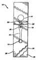
- FIG. 1is a plan view of a test strip which includes a bladder that may be actuated by the subject gimbaled bladder actuators.
- FIG. 2is an exploded view of the device of FIG. 1 .
- FIG. 3is a perspective view of the device of FIG. 1 .
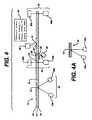
- FIG. 4is a schematic of a meter that includes a gimbaled bladder actuator according to the subject invention.
- FIG. 4Adepicts an alternative embodiment of an element of the meter of FIG. 4 .
- FIG. 5is a graph of data that is used to determine PT time.
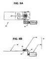
- FIG. 6Aprovides a top view of a gimbaled bladder actuator according to the subject invention
- FIG. 6Bshows a side view of the device shown in FIG. 6 A.
- FIGS. 7A and 7Bprovide top and bottom perspective views of the device shown in FIGS. 6A and 6B .
- FIG. 8Aprovides a top perspective view of the device shown in FIG. 6A
- FIG. 8Bprovides a view along line B—B of FIG. 8 A
- FIG. 8Cprovides a blow-up view of FIG. 8 B.
- Gimbaled bladder actuators and methods for their use in compressing bladders present on test stripsare provided.
- the subject actuatorsare characterized by the presence of a gimbaled compression pad under movement control of an actuating means, preferably an automated actuating means.
- meters for reading bladder including test stripsare also provided.
- the subject gimbaled bladder actuatorsare described first in greater detail, followed by a description of the test strip/meter systems with which the subject gimbaled bladder actuator find use, as well as methods for using the same.
- the subject inventionprovides bladder compressing devices or actuators that find use in compressing bladders on fluidic devices or test strips that include bladders.
- the subject bladder actuatorswill be described first in general terms, followed by a detailed discussion of a representative actuator in terms of the figures.
- a feature of the subject bladder compressing devices or actuatorsis that they include a gimbaled compression pad.
- the subject bladder actuatorsare gimbaled bladder actuators.
- gimbaled compression padis meant a planar compression element that is suspended from a holder in a manner such that the planar compression element becomes parallel to the surface it contacts during actuation.
- planar compression elementis meant a rigid piece having a substantially planar surface. The view normal to the planar surface of this element may have varying area configurations, including circular, square, rectangular, trapezoidal, oval, triangular, irregular, etc., and in many embodiments is selected so as to contact substantially all of the upper surface of a bladder of a test strip or fluidic device with which the gimbaled bladder actuator is employed.
- the actual area of the planar surfacemay vary, but is generally at least about 0.008 square inches, usually at least about 0.15 square inches and more usually at least about 0.2 square inches, where the actual area may be as great as 0.4 square inches or greater, but generally does not exceed about 0.6 square inches and usually does not exceed about 0.8 square inches. In certain embodiments, the actual area ranges from about 0.15 to 0.25 square inches, usually from about 0.19 to 0.21 square inches.
- the gimbaled compression padis characterized by being capable of applying uniform pressure to the bladder upon actuation.
- uniform pressureis meant that the pressure applied by the planar compression element at any two different locations on the bladder that is contacted by the compression element is substantially the same or identical.
- the magnitude of the variance at any two given locationstypically does not exceed about 18 lbs per square inch, usually does not exceed about 7 lbs per square inch and more usually does not exceed about 2 lbs per square inches.
- the amount of force applied by the gimbaled pad to the bladder during usetypically ranges in many embodiments from about 0.25 to 10, usually from about 0.5 to 5 and more usually from about 1.0 to 1.5 lbs.
- an actuating meansfor actuating or moving the gimbaled compression pad onto and off of a bladder of present on a test strip.
- any convenient actuating meansmay be employed that is capable of contacting the gimbaled compression pad against the bladder surface in a manner that applies substantially uniform pressure across the bladder surface, as described supra.
- the actuation meansmay be manual or automatic.
- Manual actuation meansmay simply be a compression button that can be pushed by an operator to achieve contact of the gimbaled compression pad and the bladder surface.
- the actuation meansis an automated actuation means that is capable of contacting the bladder surface with the gimbaled compression pad in a reproducible manner.
- one convenient automated actuation meansincludes the following elements: (i) a lever arm; (ii) a chassis; and (iii) a solenoid.
- this representative automated actuation meansat one end of the lever arm the gimbaled compression pad (i.e. the planar compression element and the holder) is attached.
- the lever armis such that it is capable of holding the gimbaled compression pad over, the bladder such that, upon actuation, the gimbaled compression pad contacts the bladder in a manner sufficient to compress the bladder, as described supra.
- the other end of the lever armis connected to a chassis or analogous element.
- the length of the lever armgenerally ranges from about 0.3 inches to 0.4 inches, usually from about 0.345 inches to 0.355 inches.
- the chassis or analogous elementprovides for operative communication between the lever arm and the solenoid.
- the chassismay have any convenient configuration, where a representative configuration is provided in the figures, described infra.
- the solenoidConnected to the chassis is a solenoid actuator which is capable of moving the lever arm and therefore the gimbaled compression pad in the desired manner upon actuation.
- the solenoidis generally a dual action solenoid capable of moving the gimbaled compression pad in two directions: a first direction onto the bladder and a second direction off of the bladder.
- the solenoidis under the control of a solenoid actuation means, where the means may be manual (i.e. may actuate the solenoid following direct input from a human user) or automated (i.e. may automatically actuate the solenoid following detection of an event by a sensor in a device, such as a sample placement detecting sensor).
- FIG. 6Aprovides a top view of a bladder compression device 62 of the subject invention positioned over a test strip 64 that includes a bladder.
- FIG. 6Bshows a side view of the device shown in FIG. 6 A.
- bladder compression deviceis seen placed over the end of test strip 64 .
- Bladder compression device 62includes solenoid actuation means 66 and lever arm 68 .
- gimbaled compression pad 69Located on lever arm 68 is gimbaled compression pad 69 , which is placed above bladder 63 of test strip 64 .
- FIG. 7 A and FIG. 7Bprovide top and bottom perspective views of the device shown in FIGS. 6A and 6B .
- Gimbaled compression pad 69can be seen in FIG. 7 A.
- FIG. 8Aprovides a top perspective view of the device shown in FIG. 6 A.
- bladder compression device 62is positioned over test strip 64 .
- the top of solenoid 66 and lever arm 68is visible, as well as gimbaled compression pad 69 .
- sample application region 65 of test strip 64is also visible.
- FIG. 8Bprovides a blow up view along line B—B showing gimbaled compression pad 69 .
- Gimbaled compression pad 69is made up of planar compression element 69 a in holder 69 b .
- FIG. 8Cprovides a blow-up view of FIG. 8A , showing gimbaled compression pad 69 positioned over test strip 64 .
- test strips with which the subject gimbaled bladder actuators find useare fluidic devices that generally include a sample application area; a bladder, to create a suction force to draw the sample into the device; a measurement area, in which the sample may undergo a change in an optical parameter, such as light scattering; and a stop junction to precisely stop flow after filling the measurement area.
- the test stripis substantially transparent over the measurement area, so that the area can be illuminated by a light source on one side and the transmitted light measured on the opposite side.
- FIGS. 1 , 2 and 3A representative test strip with which the subject gimbaled bladder actuators find use is shown in FIGS. 1 , 2 and 3 .
- FIG. 1provides a plan view of representative device 10
- FIG. 2provides an exploded view
- FIG. 3provides a perspective view of the same representative device.
- Sampleis applied to sample port 12 after bladder 14 has been compressed.
- the region of layer 26 and/or layer 28 that adjoins the cutout for bladder 14must be resilient, to permit bladder 14 to be compressed.
- Polyester of about 0.1 mm thicknesshas suitable resilience and springiness.
- top layer 26has a thickness of about 0.125 mm, bottom layer 28 about 0.100 mm.
- the volume of bladder 14is preferably at least about equal to the combined volume of channel 16 and measurement area 18 . If measurement area 18 is to be illuminated from below, layer 28 must be transparent where it adjoins measurement area 18 .
- stop junction 22adjoins bladder 14 and measurement area 18 ; however, a continuation of channel 16 may be on either or both sides of stop junction 22 , separating the stop junction from measurement area 18 and/or bladder 14 .
- sample flow stopsWhen the sample reaches stop junction 22 , sample flow stops.
- the principle of operation of stop junctionsis described in U.S. Pat. No. 5,230,866, incorporated herein by reference.
- all the above elementsare formed by cutouts in intermediate layer 24 , sandwiched between top layer 26 and bottom layer 28 .
- layer 24is double-sided adhesive tape.
- Stop junction 22is formed by an additional cutout in layer 26 and/or 28 , aligned with the cutout in layer 24 and sealed with sealing layer 30 and/or 32 .
- the stop junctioncomprises cutouts in both layers 26 and 28 , with sealing layers 30 and 32 .
- Each cutout for stop junction 22is at least as wide as channel 16 .
- an optional filter 12 Ato cover sample port 12 .
- the filtermay separate out red blood cells from a whole blood sample and/or may contain a reagent to interact with the blood to provide additional information.
- a suitable filtercomprises an anisotropic membrane, preferably a polysulfone membrane of the type available from Spectral Diagnostics, Inc., Toronto, Canada
- Optional reflector 18 Amay be on, or adjacent to, a surface of layer 26 and positioned over measurement area 18 . If the reflector is present, the device becomes a transflectance device.
- the test strip pictured in FIG. 2 and described aboveis preferably formed by laminating thermoplastic sheets 26 and 28 to a thermoplastic intermediate layer 24 that has adhesive on both of its surfaces.
- the cutouts that form the elements shown in FIG. 1may be formed, for example, by laser- or die-cutting of layers 24 , 26 , and 28 .
- the devicecan be formed of molded plastic.
- the surface of sheet 28is hydrophilic. (Film 9962, available from 3M, St. Paul, Minn.) However, the surfaces do not need to be hydrophilic, because the sample fluid will fill the device without capillary forces.
- sheets 26 and 28may be untreated polyester or other thermoplastic sheet, well known in the art.
- the devicecan be used in any orientation. Unlike capillary fill devices that have vent holes through which sample could leak, these types of devices vent through the sample port before sample is applied, which means that the part of the strip that is first inserted into the meter is without an opening, reducing the risk of contamination.
- the subject gimbaled bladder actuatorsfind use in meters, generally automated meters, that are designed for use with the above described test strips.
- a representative meteris depicted in FIG. 4 , where a representative test strip 10 is inserted into the meter.
- the meter shown in FIG. 4includes strip detector 40 (made up of LED 40 a and detector 40 b ), sample detector 42 (made up of light source 42 a and detector 42 b ), measurement system 44 (made up of LED 44 a and detector 44 b ), and optional heater 46 .
- the devicefurther includes a gimbaled bladder actuator 48 , which is described in greater detail supra.
- the gimbaled bladder actuatoris, in many embodiments, actuated by the strip detector 40 and the sample detector 42 , such that when a strip is inserted into the meter and detected by the strip detector, the gimbaled bladder actuator is depressed, and when the sample is added to the fluidic device or strip inserted into the meter, the gimbaled bladder actuator is withdrawn so as to decompress the bladder and concomitantly pull sample into the measurement area of the device via the resultant negative pressure conditions in the fluid channel(s) of the test strip.
- a meter display 50that provides for an interface with the user.
- test strip/meter systemsthat include the subject gimbaled bladder actuators are suitable for use in a variety of analytical tests of biological fluids, such as determining biochemical or hematological characteristics, or measuring the concentration in such fluids of analytes such as proteins, hormones, carbohydrates, lipids, drugs, toxins, gases, electrolytes, etc.
- analytessuch as proteins, hormones, carbohydrates, lipids, drugs, toxins, gases, electrolytes, etc.
- the procedures for performing these testshave been described in the literature. Among the tests, and where they are described, are the following: (1) Chromogenic Factor XIIa Assay (and other clotting factors as well): Rand, M. D. et al., Blood, 88, 3432 (1996); (2) Factor X Assay: Bick, R. L.
- test strip/meter systemsare particularly well suited for measuring blood-clotting time—“prothrombin time” or “PT time,” as more fully described in U.S. Pat. No. 6,521,182, filed Jun. 15, 1999; and U.S. Pat. No. 6,261,519, filed Jul. 16, 1999; the disclosures of which are herein incorporated by reference.
- PT timeblood-clotting time
- the first step the user performsis to turn on the meter, thereby energizing strip detector 40 , sample detector 42 , measurement system 44 , and optional heater 46 .
- the second stepis to insert the strip.
- the stripis not transparent over at least a part of its area, so that an inserted strip will block the illumination by LED 40 a of detector 40 b .
- the intermediate layeris formed of a non-transparent material, so that background light does not enter measurement system 44 .
- Detector 40 bthereby senses that a strip has been inserted and triggers gimbaled bladder actuator 48 to compress bladder 14 .
- a meter display 50then directs the user to apply a sample to sample port 12 as the third and last step the user must perform to initiate the measurement sequence.
- the empty sample portis reflective.
- a sampleWhen a sample is introduced into the sample port, it absorbs light from LED 42 a and thereby reduces the light that is reflected to detector 42 b . That reduction in light, in turn, signals gimbaled bladder actuator 48 to release bladder 14 .
- the resultant suction in channel 16draws sample through measurement area 18 to stop junction 22 .
- Light from LED 44 apasses through measurement area 18 , and detector 44 b monitors the light transmitted through the sample as it is clotting. Analysis of the transmitted light as a function of time (as described below) permits a calculation of the PT time, which is displayed on the meter display 50 .
- sample temperatureis maintained at about 39° C. by heater 46 .
- the detectorsenses a sample in sample port 12 , simply by detecting a reduction in (specular) reflection of a light signal that is emitted by 42 a and detected by 42 b .
- a simple systemcannot easily distinguish between a whole blood sample and some other liquid (e.g., blood serum) placed in the sample port in error or, even, an object (e.g., a finger) that can approach sample port 12 and cause the system to erroneously conclude that a proper sample has been applied.
- another embodimentmeasures diffuse reflection from the sample port. This embodiment appears in FIG. 4A , which shows detector 42 b positioned normal to the plane of strip 10 . With the arrangement shown in FIG.
- the signal detected by 42 bincreases abruptly, because of scattering in the blood sample, then decreases, because of rouleaux formation.
- the detector system 42is thus programmed to require that type of signal before causing gimbaled bladder actuator 48 to release bladder 14 .
- the delay of several seconds in releasing bladder 14does not substantially affect the readings described below.
- FIG. 5depicts a typical “clot signature” curve in which the current from detector 44 b is plotted as a function of time.
- Bloodis first detected in the measurement area by 44 b at time 1.
- the bloodfills the measurement area.
- the reduction in current during that time intervalis due to light scattered by red cells and is thus an approximate measure of the hematocrit.
- samplehas filled the measurement area and is at rest, its movement having been stopped by the stop junction.
- the red cellsbegin to stack up like coins (rouleaux formation).
- the rouleaux effectallows increasing light transmission through the sample (and less scattering) in the time interval between points 2 and 3.
- clot formationends rouleaux formation and transmission through the sample reaches a maximum.
- the PT timecan be calculated from the interval B between points 1 and 3 or between 2 and 3. Thereafter, blood changes state from liquid to a semi-solid gel, with a corresponding reduction in light transmission.
- the reduction in C current C between the maximum 3 and endpoint 4correlates with fibrinogen in the sample.
- the subject inventionprovides a means for applying uniform and reproducible bladder compression and decompression in test strips that include bladders.
- the subject devicesprovide for the elimination of a source of error in analytical assays using such test strips.
- the subject inventionrepresents a significant contribution to the art.
Landscapes
- Chemical & Material Sciences (AREA)
- Health & Medical Sciences (AREA)
- Clinical Laboratory Science (AREA)
- Chemical Kinetics & Catalysis (AREA)
- Dispersion Chemistry (AREA)
- Analytical Chemistry (AREA)
- General Health & Medical Sciences (AREA)
- Hematology (AREA)
- Investigating Or Analysing Biological Materials (AREA)
- Investigating Strength Of Materials By Application Of Mechanical Stress (AREA)
- Investigating Or Analysing Materials By Optical Means (AREA)
- Sampling And Sample Adjustment (AREA)
- Optical Measuring Cells (AREA)
- Automatic Analysis And Handling Materials Therefor (AREA)
- Accommodation For Nursing Or Treatment Tables (AREA)
- Apparatus For Radiation Diagnosis (AREA)
Abstract
Description
Claims (15)
Priority Applications (23)
| Application Number | Priority Date | Filing Date | Title |
|---|---|---|---|
| US09/637,504US6866822B1 (en) | 2000-08-11 | 2000-08-11 | Gimbaled bladder actuator for use with test strips |
| DK01961740TDK1311862T3 (en) | 2000-08-11 | 2001-07-26 | Automatic measuring instrument with a cardan-suspended bladder drive device for use with test strips |
| MXPA03001090AMXPA03001090A (en) | 2000-08-11 | 2001-07-26 | Gimbaled bladder actuator for use with test strips. |
| AT01961740TATE313081T1 (en) | 2000-08-11 | 2001-07-26 | AUTOMATIC METER WITH A CARDAN BUBBLE DRIVE DEVICE FOR USE WITH TEST STRIPS |
| HK03105078.1AHK1052745B (en) | 2000-08-11 | 2001-07-26 | Automatic meters including a gimbaled bladder actuator for use with test strips |
| AU2001282985AAU2001282985B2 (en) | 2000-08-11 | 2001-07-26 | Gimbaled bladder actuator for use with test strips |
| PCT/US2001/023531WO2002013970A2 (en) | 2000-08-11 | 2001-07-26 | Gimbaled bladder actuator for use with test strips |
| CNA018172229ACN1469997A (en) | 2000-08-11 | 2001-07-26 | Cardanized bladder actuator for use with test strips |
| CA002418693ACA2418693A1 (en) | 2000-08-11 | 2001-07-26 | Gimbaled bladder actuator for use with test strips |
| DE60115916TDE60115916T2 (en) | 2000-08-11 | 2001-07-26 | AUTOMATIC METER WITH A CARDANIAN BUBBLE DRIVE DEVICE FOR USE WITH TEST STRIPS |
| IL15422101AIL154221A0 (en) | 2000-08-11 | 2001-07-26 | Gimbaled bladder actuator for use with test strips |
| ES01961740TES2253412T3 (en) | 2000-08-11 | 2001-07-26 | AUTOMATIC METER THAT INCLUDES A CARDANIC CAMERA ACTIVATOR FOR USE WITH ANALYSIS STRIPS. |
| EP01961740AEP1311862B1 (en) | 2000-08-11 | 2001-07-26 | Automatic meters including a gimbaled bladder actuator for use with test strips |
| CZ2003399ACZ2003399A3 (en) | 2000-08-11 | 2001-07-26 | Gimbaled bladder actuator for use with test strips |
| JP2002519101AJP2004512501A (en) | 2000-08-11 | 2001-07-26 | Gimbal capsule actuator for use with test specimens |
| PL01359932APL359932A1 (en) | 2000-08-11 | 2001-07-26 | Gimbaled bladder actuator for use with test strips |
| RU2003103852/14ARU2003103852A (en) | 2000-08-11 | 2001-07-26 | SWIVEL ACTUATOR OF AN ELASTIC CYLINDER FOR APPLICATION WITH TESTING STRIPES |
| KR10-2003-7001781AKR20030033021A (en) | 2000-08-11 | 2001-07-26 | Gimbaled bladder actuator for use with test strips |
| AU8298501AAU8298501A (en) | 2000-08-11 | 2001-07-26 | Gimbaled bladder actuator for use with test strips |
| MYPI20013753MY133947A (en) | 2000-08-11 | 2001-08-09 | Gimbaled bladder actuator for use with test strips |
| TW090119565ATW550115B (en) | 2000-08-11 | 2001-08-10 | Gimbaled bladder actuator for use with test strips |
| ARP010103844AAR030343A1 (en) | 2000-08-11 | 2001-08-10 | AMPOLLA ACTUATOR IN CARDANIC SUSPENSION FOR USE WITH ANALYSIS STRIPS |
| NO20030616ANO20030616L (en) | 2000-08-11 | 2003-02-07 | Cardanic bleeder controller for use with test strips |
Applications Claiming Priority (1)
| Application Number | Priority Date | Filing Date | Title |
|---|---|---|---|
| US09/637,504US6866822B1 (en) | 2000-08-11 | 2000-08-11 | Gimbaled bladder actuator for use with test strips |
Publications (1)
| Publication Number | Publication Date |
|---|---|
| US6866822B1true US6866822B1 (en) | 2005-03-15 |
Family
ID=24556216
Family Applications (1)
| Application Number | Title | Priority Date | Filing Date |
|---|---|---|---|
| US09/637,504Expired - LifetimeUS6866822B1 (en) | 2000-08-11 | 2000-08-11 | Gimbaled bladder actuator for use with test strips |
Country Status (22)
| Country | Link |
|---|---|
| US (1) | US6866822B1 (en) |
| EP (1) | EP1311862B1 (en) |
| JP (1) | JP2004512501A (en) |
| KR (1) | KR20030033021A (en) |
| CN (1) | CN1469997A (en) |
| AR (1) | AR030343A1 (en) |
| AT (1) | ATE313081T1 (en) |
| AU (2) | AU8298501A (en) |
| CA (1) | CA2418693A1 (en) |
| CZ (1) | CZ2003399A3 (en) |
| DE (1) | DE60115916T2 (en) |
| DK (1) | DK1311862T3 (en) |
| ES (1) | ES2253412T3 (en) |
| HK (1) | HK1052745B (en) |
| IL (1) | IL154221A0 (en) |
| MX (1) | MXPA03001090A (en) |
| MY (1) | MY133947A (en) |
| NO (1) | NO20030616L (en) |
| PL (1) | PL359932A1 (en) |
| RU (1) | RU2003103852A (en) |
| TW (1) | TW550115B (en) |
| WO (1) | WO2002013970A2 (en) |
Cited By (56)
| Publication number | Priority date | Publication date | Assignee | Title |
|---|---|---|---|---|
| US20020110922A1 (en)* | 1998-07-20 | 2002-08-15 | Shartle Robert Justice | Vacuum loaded test strip and method of use |
| US20050220629A1 (en)* | 2004-03-31 | 2005-10-06 | Sebastian Bohm | Method of segregating a bolus of fluid using a pneumatic actuator in a fluid handling circuit |
| US20050220630A1 (en)* | 2004-03-31 | 2005-10-06 | Sebastian Bohm | Method of using triggerable passive valves to control the flow of fluid |
| US20050220644A1 (en)* | 2004-03-31 | 2005-10-06 | Sebastian Bohm | Pneumatic actuator for bolus generation in a fluid handling circuit |
| US20050217743A1 (en)* | 2004-03-31 | 2005-10-06 | Sebastian Bohm | Triggerable passive valve for use in controlling the flow of fluid |
| US20050217741A1 (en)* | 2004-03-31 | 2005-10-06 | Sebastian Bohm | Method of controlling the movement of fluid through a microfluidic circuit using an array oftriggerable passive valves |
| US20050217742A1 (en)* | 2004-03-31 | 2005-10-06 | Sebastian Bohm | Microfluidic circuit including an array of triggerable passive valves |
| US7875047B2 (en) | 2002-04-19 | 2011-01-25 | Pelikan Technologies, Inc. | Method and apparatus for a multi-use body fluid sampling device with sterility barrier release |
| US7892183B2 (en) | 2002-04-19 | 2011-02-22 | Pelikan Technologies, Inc. | Method and apparatus for body fluid sampling and analyte sensing |
| US7901365B2 (en) | 2002-04-19 | 2011-03-08 | Pelikan Technologies, Inc. | Method and apparatus for penetrating tissue |
| US7909774B2 (en) | 2002-04-19 | 2011-03-22 | Pelikan Technologies, Inc. | Method and apparatus for penetrating tissue |
| US7909775B2 (en) | 2001-06-12 | 2011-03-22 | Pelikan Technologies, Inc. | Method and apparatus for lancet launching device integrated onto a blood-sampling cartridge |
| US7909777B2 (en) | 2002-04-19 | 2011-03-22 | Pelikan Technologies, Inc | Method and apparatus for penetrating tissue |
| US7909778B2 (en) | 2002-04-19 | 2011-03-22 | Pelikan Technologies, Inc. | Method and apparatus for penetrating tissue |
| US7914465B2 (en) | 2002-04-19 | 2011-03-29 | Pelikan Technologies, Inc. | Method and apparatus for penetrating tissue |
| US7976476B2 (en) | 2002-04-19 | 2011-07-12 | Pelikan Technologies, Inc. | Device and method for variable speed lancet |
| US7981056B2 (en) | 2002-04-19 | 2011-07-19 | Pelikan Technologies, Inc. | Methods and apparatus for lancet actuation |
| US7981055B2 (en) | 2001-06-12 | 2011-07-19 | Pelikan Technologies, Inc. | Tissue penetration device |
| US7988645B2 (en) | 2001-06-12 | 2011-08-02 | Pelikan Technologies, Inc. | Self optimizing lancing device with adaptation means to temporal variations in cutaneous properties |
| US8007446B2 (en) | 2002-04-19 | 2011-08-30 | Pelikan Technologies, Inc. | Method and apparatus for penetrating tissue |
| US8062231B2 (en) | 2002-04-19 | 2011-11-22 | Pelikan Technologies, Inc. | Method and apparatus for penetrating tissue |
| US8079960B2 (en) | 2002-04-19 | 2011-12-20 | Pelikan Technologies, Inc. | Methods and apparatus for lancet actuation |
| US8197421B2 (en) | 2002-04-19 | 2012-06-12 | Pelikan Technologies, Inc. | Method and apparatus for penetrating tissue |
| US8221334B2 (en) | 2002-04-19 | 2012-07-17 | Sanofi-Aventis Deutschland Gmbh | Method and apparatus for penetrating tissue |
| US8251921B2 (en) | 2003-06-06 | 2012-08-28 | Sanofi-Aventis Deutschland Gmbh | Method and apparatus for body fluid sampling and analyte sensing |
| US8262614B2 (en) | 2003-05-30 | 2012-09-11 | Pelikan Technologies, Inc. | Method and apparatus for fluid injection |
| US8267870B2 (en) | 2002-04-19 | 2012-09-18 | Sanofi-Aventis Deutschland Gmbh | Method and apparatus for body fluid sampling with hybrid actuation |
| US8282576B2 (en) | 2003-09-29 | 2012-10-09 | Sanofi-Aventis Deutschland Gmbh | Method and apparatus for an improved sample capture device |
| US8296918B2 (en) | 2003-12-31 | 2012-10-30 | Sanofi-Aventis Deutschland Gmbh | Method of manufacturing a fluid sampling device with improved analyte detecting member configuration |
| US8333710B2 (en) | 2002-04-19 | 2012-12-18 | Sanofi-Aventis Deutschland Gmbh | Tissue penetration device |
| US8360992B2 (en) | 2002-04-19 | 2013-01-29 | Sanofi-Aventis Deutschland Gmbh | Method and apparatus for penetrating tissue |
| US8372016B2 (en) | 2002-04-19 | 2013-02-12 | Sanofi-Aventis Deutschland Gmbh | Method and apparatus for body fluid sampling and analyte sensing |
| US8382682B2 (en) | 2002-04-19 | 2013-02-26 | Sanofi-Aventis Deutschland Gmbh | Method and apparatus for penetrating tissue |
| US8435190B2 (en) | 2002-04-19 | 2013-05-07 | Sanofi-Aventis Deutschland Gmbh | Method and apparatus for penetrating tissue |
| US8439872B2 (en) | 1998-03-30 | 2013-05-14 | Sanofi-Aventis Deutschland Gmbh | Apparatus and method for penetration with shaft having a sensor for sensing penetration depth |
| US8556829B2 (en) | 2002-04-19 | 2013-10-15 | Sanofi-Aventis Deutschland Gmbh | Method and apparatus for penetrating tissue |
| US8574895B2 (en) | 2002-12-30 | 2013-11-05 | Sanofi-Aventis Deutschland Gmbh | Method and apparatus using optical techniques to measure analyte levels |
| US8641644B2 (en) | 2000-11-21 | 2014-02-04 | Sanofi-Aventis Deutschland Gmbh | Blood testing apparatus having a rotatable cartridge with multiple lancing elements and testing means |
| US8652831B2 (en) | 2004-12-30 | 2014-02-18 | Sanofi-Aventis Deutschland Gmbh | Method and apparatus for analyte measurement test time |
| US8668656B2 (en) | 2003-12-31 | 2014-03-11 | Sanofi-Aventis Deutschland Gmbh | Method and apparatus for improving fluidic flow and sample capture |
| US8702624B2 (en) | 2006-09-29 | 2014-04-22 | Sanofi-Aventis Deutschland Gmbh | Analyte measurement device with a single shot actuator |
| US8721671B2 (en) | 2001-06-12 | 2014-05-13 | Sanofi-Aventis Deutschland Gmbh | Electric lancet actuator |
| US8784335B2 (en) | 2002-04-19 | 2014-07-22 | Sanofi-Aventis Deutschland Gmbh | Body fluid sampling device with a capacitive sensor |
| US8828203B2 (en) | 2004-05-20 | 2014-09-09 | Sanofi-Aventis Deutschland Gmbh | Printable hydrogels for biosensors |
| US8965476B2 (en) | 2010-04-16 | 2015-02-24 | Sanofi-Aventis Deutschland Gmbh | Tissue penetration device |
| US9144401B2 (en) | 2003-06-11 | 2015-09-29 | Sanofi-Aventis Deutschland Gmbh | Low pain penetrating member |
| US9226699B2 (en) | 2002-04-19 | 2016-01-05 | Sanofi-Aventis Deutschland Gmbh | Body fluid sampling module with a continuous compression tissue interface surface |
| US9248267B2 (en) | 2002-04-19 | 2016-02-02 | Sanofi-Aventis Deustchland Gmbh | Tissue penetration device |
| US9314194B2 (en) | 2002-04-19 | 2016-04-19 | Sanofi-Aventis Deutschland Gmbh | Tissue penetration device |
| US9351680B2 (en) | 2003-10-14 | 2016-05-31 | Sanofi-Aventis Deutschland Gmbh | Method and apparatus for a variable user interface |
| US9375169B2 (en) | 2009-01-30 | 2016-06-28 | Sanofi-Aventis Deutschland Gmbh | Cam drive for managing disposable penetrating member actions with a single motor and motor and control system |
| US9386944B2 (en) | 2008-04-11 | 2016-07-12 | Sanofi-Aventis Deutschland Gmbh | Method and apparatus for analyte detecting device |
| US9427532B2 (en) | 2001-06-12 | 2016-08-30 | Sanofi-Aventis Deutschland Gmbh | Tissue penetration device |
| US9775553B2 (en) | 2004-06-03 | 2017-10-03 | Sanofi-Aventis Deutschland Gmbh | Method and apparatus for a fluid sampling device |
| US9795747B2 (en) | 2010-06-02 | 2017-10-24 | Sanofi-Aventis Deutschland Gmbh | Methods and apparatus for lancet actuation |
| US9820684B2 (en) | 2004-06-03 | 2017-11-21 | Sanofi-Aventis Deutschland Gmbh | Method and apparatus for a fluid sampling device |
Families Citing this family (7)
| Publication number | Priority date | Publication date | Assignee | Title |
|---|---|---|---|---|
| US7452457B2 (en) | 2003-06-20 | 2008-11-18 | Roche Diagnostics Operations, Inc. | System and method for analyte measurement using dose sufficiency electrodes |
| US7604721B2 (en) | 2003-06-20 | 2009-10-20 | Roche Diagnostics Operations, Inc. | System and method for coding information on a biosensor test strip |
| US7597793B2 (en) | 2003-06-20 | 2009-10-06 | Roche Operations Ltd. | System and method for analyte measurement employing maximum dosing time delay |
| US7556723B2 (en) | 2004-06-18 | 2009-07-07 | Roche Diagnostics Operations, Inc. | Electrode design for biosensor |
| US7569126B2 (en) | 2004-06-18 | 2009-08-04 | Roche Diagnostics Operations, Inc. | System and method for quality assurance of a biosensor test strip |
| CN102164531A (en)* | 2008-08-05 | 2011-08-24 | 美艾利尔瑞士股份有限公司 | A universal testing platform for medical diagnostics and an apparatus for reading testing platforms |
| DE102019215952A1 (en)* | 2019-10-16 | 2021-04-22 | Robert Bosch Gmbh | Diaphragm pump, system and method for the optical determination of a deflection state of a diaphragm of the diaphragm pump |
Citations (20)
| Publication number | Priority date | Publication date | Assignee | Title |
|---|---|---|---|---|
| US3620676A (en) | 1969-02-20 | 1971-11-16 | Sterilizer Control Royalties A | Disposable colorimetric indicator and sampling device for liquids |
| US3640267A (en) | 1969-12-15 | 1972-02-08 | Damon Corp | Clinical sample container |
| US4088448A (en) | 1975-09-29 | 1978-05-09 | Lilja Jan Evert | Apparatus for sampling, mixing the sample with a reagent and making particularly optical analyses |
| US4426451A (en) | 1981-01-28 | 1984-01-17 | Eastman Kodak Company | Multi-zoned reaction vessel having pressure-actuatable control means between zones |
| US4480685A (en) | 1980-09-03 | 1984-11-06 | Gilbertson Thomas A | Oil well pump driving unit |
| US4868129A (en) | 1987-08-27 | 1989-09-19 | Biotrack Inc. | Apparatus and method for dilution and mixing of liquid samples |
| EP0374115A1 (en) | 1988-12-08 | 1990-06-20 | Humanteknik AB | Positive displacement pump |
| US5104813A (en) | 1989-04-13 | 1992-04-14 | Biotrack, Inc. | Dilution and mixing cartridge |
| US5208163A (en) | 1990-08-06 | 1993-05-04 | Miles Inc. | Self-metering fluid analysis device |
| US5230866A (en) | 1991-03-01 | 1993-07-27 | Biotrack, Inc. | Capillary stop-flow junction having improved stability against accidental fluid flow |
| US5252044A (en) | 1992-10-20 | 1993-10-12 | Medflow, Inc. | Parenteral fluid pump with disposable cassette |
| US5302093A (en) | 1992-05-01 | 1994-04-12 | Mcgaw, Inc. | Disposable cassette with negative head height fluid supply and method |
| US5309176A (en) | 1992-08-25 | 1994-05-03 | Sci Systems, Inc. | Airline ticket printer with stepper motor for selectively engaging print head and platen |
| WO1995012117A1 (en) | 1993-10-28 | 1995-05-04 | I-Stat Corporation | Apparatus for assaying viscosity changes in fluid samples and method of conducting same |
| EP0803288A2 (en) | 1996-04-26 | 1997-10-29 | Kyoto Daiichi Kagaku Co., Ltd. | Device and method for analyzing a sample |
| US5700695A (en) | 1994-06-30 | 1997-12-23 | Zia Yassinzadeh | Sample collection and manipulation method |
| US5736404A (en)* | 1995-12-27 | 1998-04-07 | Zia Yassinzadeh | Flow detection appartus and method |
| WO1999034957A1 (en) | 1998-01-12 | 1999-07-15 | Speedfam-Ipec Corporation | Workpiece carrier with monopiece pressure plate and low gimbal point |
| US20030044318A1 (en)* | 2001-09-05 | 2003-03-06 | Lorin Olson | Devices for analyte concentration determination and methods of using the same |
| US6652814B1 (en)* | 2000-08-11 | 2003-11-25 | Lifescan, Inc. | Strip holder for use in a test strip meter |
- 2000
- 2000-08-11USUS09/637,504patent/US6866822B1/ennot_activeExpired - Lifetime
- 2001
- 2001-07-26DEDE60115916Tpatent/DE60115916T2/ennot_activeExpired - Lifetime
- 2001-07-26WOPCT/US2001/023531patent/WO2002013970A2/enactiveIP Right Grant
- 2001-07-26AUAU8298501Apatent/AU8298501A/enactivePending
- 2001-07-26HKHK03105078.1Apatent/HK1052745B/ennot_activeIP Right Cessation
- 2001-07-26MXMXPA03001090Apatent/MXPA03001090A/enunknown
- 2001-07-26CACA002418693Apatent/CA2418693A1/ennot_activeAbandoned
- 2001-07-26ILIL15422101Apatent/IL154221A0/enunknown
- 2001-07-26EPEP01961740Apatent/EP1311862B1/ennot_activeExpired - Lifetime
- 2001-07-26AUAU2001282985Apatent/AU2001282985B2/ennot_activeCeased
- 2001-07-26PLPL01359932Apatent/PL359932A1/ennot_activeApplication Discontinuation
- 2001-07-26RURU2003103852/14Apatent/RU2003103852A/ennot_activeApplication Discontinuation
- 2001-07-26ESES01961740Tpatent/ES2253412T3/ennot_activeExpired - Lifetime
- 2001-07-26JPJP2002519101Apatent/JP2004512501A/enactivePending
- 2001-07-26ATAT01961740Tpatent/ATE313081T1/enactive
- 2001-07-26DKDK01961740Tpatent/DK1311862T3/enactive
- 2001-07-26CZCZ2003399Apatent/CZ2003399A3/enunknown
- 2001-07-26KRKR10-2003-7001781Apatent/KR20030033021A/ennot_activeWithdrawn
- 2001-07-26CNCNA018172229Apatent/CN1469997A/enactivePending
- 2001-08-09MYMYPI20013753patent/MY133947A/enunknown
- 2001-08-10TWTW090119565Apatent/TW550115B/ennot_activeIP Right Cessation
- 2001-08-10ARARP010103844Apatent/AR030343A1/enunknown
- 2003
- 2003-02-07NONO20030616Apatent/NO20030616L/ennot_activeApplication Discontinuation
Patent Citations (20)
| Publication number | Priority date | Publication date | Assignee | Title |
|---|---|---|---|---|
| US3620676A (en) | 1969-02-20 | 1971-11-16 | Sterilizer Control Royalties A | Disposable colorimetric indicator and sampling device for liquids |
| US3640267A (en) | 1969-12-15 | 1972-02-08 | Damon Corp | Clinical sample container |
| US4088448A (en) | 1975-09-29 | 1978-05-09 | Lilja Jan Evert | Apparatus for sampling, mixing the sample with a reagent and making particularly optical analyses |
| US4480685A (en) | 1980-09-03 | 1984-11-06 | Gilbertson Thomas A | Oil well pump driving unit |
| US4426451A (en) | 1981-01-28 | 1984-01-17 | Eastman Kodak Company | Multi-zoned reaction vessel having pressure-actuatable control means between zones |
| US4868129A (en) | 1987-08-27 | 1989-09-19 | Biotrack Inc. | Apparatus and method for dilution and mixing of liquid samples |
| EP0374115A1 (en) | 1988-12-08 | 1990-06-20 | Humanteknik AB | Positive displacement pump |
| US5104813A (en) | 1989-04-13 | 1992-04-14 | Biotrack, Inc. | Dilution and mixing cartridge |
| US5208163A (en) | 1990-08-06 | 1993-05-04 | Miles Inc. | Self-metering fluid analysis device |
| US5230866A (en) | 1991-03-01 | 1993-07-27 | Biotrack, Inc. | Capillary stop-flow junction having improved stability against accidental fluid flow |
| US5302093A (en) | 1992-05-01 | 1994-04-12 | Mcgaw, Inc. | Disposable cassette with negative head height fluid supply and method |
| US5309176A (en) | 1992-08-25 | 1994-05-03 | Sci Systems, Inc. | Airline ticket printer with stepper motor for selectively engaging print head and platen |
| US5252044A (en) | 1992-10-20 | 1993-10-12 | Medflow, Inc. | Parenteral fluid pump with disposable cassette |
| WO1995012117A1 (en) | 1993-10-28 | 1995-05-04 | I-Stat Corporation | Apparatus for assaying viscosity changes in fluid samples and method of conducting same |
| US5700695A (en) | 1994-06-30 | 1997-12-23 | Zia Yassinzadeh | Sample collection and manipulation method |
| US5736404A (en)* | 1995-12-27 | 1998-04-07 | Zia Yassinzadeh | Flow detection appartus and method |
| EP0803288A2 (en) | 1996-04-26 | 1997-10-29 | Kyoto Daiichi Kagaku Co., Ltd. | Device and method for analyzing a sample |
| WO1999034957A1 (en) | 1998-01-12 | 1999-07-15 | Speedfam-Ipec Corporation | Workpiece carrier with monopiece pressure plate and low gimbal point |
| US6652814B1 (en)* | 2000-08-11 | 2003-11-25 | Lifescan, Inc. | Strip holder for use in a test strip meter |
| US20030044318A1 (en)* | 2001-09-05 | 2003-03-06 | Lorin Olson | Devices for analyte concentration determination and methods of using the same |
Non-Patent Citations (1)
| Title |
|---|
| Gimbal definition from English Oxford Dictionary online: http://dictionary.oed.com/cgi/entry/00094657?signle=1&query-type=work&queryword=gimbal&edition=2e&first=1&max to show=10. |
Cited By (118)
| Publication number | Priority date | Publication date | Assignee | Title |
|---|---|---|---|---|
| US8439872B2 (en) | 1998-03-30 | 2013-05-14 | Sanofi-Aventis Deutschland Gmbh | Apparatus and method for penetration with shaft having a sensor for sensing penetration depth |
| US20020110922A1 (en)* | 1998-07-20 | 2002-08-15 | Shartle Robert Justice | Vacuum loaded test strip and method of use |
| US8641644B2 (en) | 2000-11-21 | 2014-02-04 | Sanofi-Aventis Deutschland Gmbh | Blood testing apparatus having a rotatable cartridge with multiple lancing elements and testing means |
| US7909775B2 (en) | 2001-06-12 | 2011-03-22 | Pelikan Technologies, Inc. | Method and apparatus for lancet launching device integrated onto a blood-sampling cartridge |
| US8360991B2 (en) | 2001-06-12 | 2013-01-29 | Sanofi-Aventis Deutschland Gmbh | Tissue penetration device |
| US9427532B2 (en) | 2001-06-12 | 2016-08-30 | Sanofi-Aventis Deutschland Gmbh | Tissue penetration device |
| US8845550B2 (en) | 2001-06-12 | 2014-09-30 | Sanofi-Aventis Deutschland Gmbh | Tissue penetration device |
| US8721671B2 (en) | 2001-06-12 | 2014-05-13 | Sanofi-Aventis Deutschland Gmbh | Electric lancet actuator |
| US8679033B2 (en) | 2001-06-12 | 2014-03-25 | Sanofi-Aventis Deutschland Gmbh | Tissue penetration device |
| US9694144B2 (en) | 2001-06-12 | 2017-07-04 | Sanofi-Aventis Deutschland Gmbh | Sampling module device and method |
| US8641643B2 (en) | 2001-06-12 | 2014-02-04 | Sanofi-Aventis Deutschland Gmbh | Sampling module device and method |
| US8622930B2 (en) | 2001-06-12 | 2014-01-07 | Sanofi-Aventis Deutschland Gmbh | Tissue penetration device |
| US9802007B2 (en) | 2001-06-12 | 2017-10-31 | Sanofi-Aventis Deutschland Gmbh | Methods and apparatus for lancet actuation |
| US9937298B2 (en) | 2001-06-12 | 2018-04-10 | Sanofi-Aventis Deutschland Gmbh | Tissue penetration device |
| US8123700B2 (en) | 2001-06-12 | 2012-02-28 | Pelikan Technologies, Inc. | Method and apparatus for lancet launching device integrated onto a blood-sampling cartridge |
| US8382683B2 (en) | 2001-06-12 | 2013-02-26 | Sanofi-Aventis Deutschland Gmbh | Tissue penetration device |
| US8162853B2 (en) | 2001-06-12 | 2012-04-24 | Pelikan Technologies, Inc. | Tissue penetration device |
| US8343075B2 (en) | 2001-06-12 | 2013-01-01 | Sanofi-Aventis Deutschland Gmbh | Tissue penetration device |
| US8337421B2 (en) | 2001-06-12 | 2012-12-25 | Sanofi-Aventis Deutschland Gmbh | Tissue penetration device |
| US8282577B2 (en) | 2001-06-12 | 2012-10-09 | Sanofi-Aventis Deutschland Gmbh | Method and apparatus for lancet launching device integrated onto a blood-sampling cartridge |
| US8216154B2 (en) | 2001-06-12 | 2012-07-10 | Sanofi-Aventis Deutschland Gmbh | Tissue penetration device |
| US8211037B2 (en) | 2001-06-12 | 2012-07-03 | Pelikan Technologies, Inc. | Tissue penetration device |
| US7981055B2 (en) | 2001-06-12 | 2011-07-19 | Pelikan Technologies, Inc. | Tissue penetration device |
| US8206319B2 (en) | 2001-06-12 | 2012-06-26 | Sanofi-Aventis Deutschland Gmbh | Tissue penetration device |
| US7988645B2 (en) | 2001-06-12 | 2011-08-02 | Pelikan Technologies, Inc. | Self optimizing lancing device with adaptation means to temporal variations in cutaneous properties |
| US8206317B2 (en) | 2001-06-12 | 2012-06-26 | Sanofi-Aventis Deutschland Gmbh | Tissue penetration device |
| US8016774B2 (en) | 2001-06-12 | 2011-09-13 | Pelikan Technologies, Inc. | Tissue penetration device |
| US9560993B2 (en) | 2001-11-21 | 2017-02-07 | Sanofi-Aventis Deutschland Gmbh | Blood testing apparatus having a rotatable cartridge with multiple lancing elements and testing means |
| US8388551B2 (en) | 2002-04-19 | 2013-03-05 | Sanofi-Aventis Deutschland Gmbh | Method and apparatus for multi-use body fluid sampling device with sterility barrier release |
| US7875047B2 (en) | 2002-04-19 | 2011-01-25 | Pelikan Technologies, Inc. | Method and apparatus for a multi-use body fluid sampling device with sterility barrier release |
| US8157748B2 (en) | 2002-04-19 | 2012-04-17 | Pelikan Technologies, Inc. | Methods and apparatus for lancet actuation |
| US8062231B2 (en) | 2002-04-19 | 2011-11-22 | Pelikan Technologies, Inc. | Method and apparatus for penetrating tissue |
| US8197421B2 (en) | 2002-04-19 | 2012-06-12 | Pelikan Technologies, Inc. | Method and apparatus for penetrating tissue |
| US8197423B2 (en) | 2002-04-19 | 2012-06-12 | Pelikan Technologies, Inc. | Method and apparatus for penetrating tissue |
| US8202231B2 (en) | 2002-04-19 | 2012-06-19 | Sanofi-Aventis Deutschland Gmbh | Method and apparatus for penetrating tissue |
| US8007446B2 (en) | 2002-04-19 | 2011-08-30 | Pelikan Technologies, Inc. | Method and apparatus for penetrating tissue |
| US7988644B2 (en) | 2002-04-19 | 2011-08-02 | Pelikan Technologies, Inc. | Method and apparatus for a multi-use body fluid sampling device with sterility barrier release |
| US7981056B2 (en) | 2002-04-19 | 2011-07-19 | Pelikan Technologies, Inc. | Methods and apparatus for lancet actuation |
| US7976476B2 (en) | 2002-04-19 | 2011-07-12 | Pelikan Technologies, Inc. | Device and method for variable speed lancet |
| US8221334B2 (en) | 2002-04-19 | 2012-07-17 | Sanofi-Aventis Deutschland Gmbh | Method and apparatus for penetrating tissue |
| US8235915B2 (en) | 2002-04-19 | 2012-08-07 | Sanofi-Aventis Deutschland Gmbh | Method and apparatus for penetrating tissue |
| US9907502B2 (en) | 2002-04-19 | 2018-03-06 | Sanofi-Aventis Deutschland Gmbh | Method and apparatus for penetrating tissue |
| US9839386B2 (en) | 2002-04-19 | 2017-12-12 | Sanofi-Aventis Deustschland Gmbh | Body fluid sampling device with capacitive sensor |
| US8267870B2 (en) | 2002-04-19 | 2012-09-18 | Sanofi-Aventis Deutschland Gmbh | Method and apparatus for body fluid sampling with hybrid actuation |
| US9795334B2 (en) | 2002-04-19 | 2017-10-24 | Sanofi-Aventis Deutschland Gmbh | Method and apparatus for penetrating tissue |
| US7959582B2 (en) | 2002-04-19 | 2011-06-14 | Pelikan Technologies, Inc. | Method and apparatus for penetrating tissue |
| US9724021B2 (en) | 2002-04-19 | 2017-08-08 | Sanofi-Aventis Deutschland Gmbh | Method and apparatus for penetrating tissue |
| US8333710B2 (en) | 2002-04-19 | 2012-12-18 | Sanofi-Aventis Deutschland Gmbh | Tissue penetration device |
| US8337419B2 (en) | 2002-04-19 | 2012-12-25 | Sanofi-Aventis Deutschland Gmbh | Tissue penetration device |
| US7938787B2 (en) | 2002-04-19 | 2011-05-10 | Pelikan Technologies, Inc. | Method and apparatus for penetrating tissue |
| US8337420B2 (en) | 2002-04-19 | 2012-12-25 | Sanofi-Aventis Deutschland Gmbh | Tissue penetration device |
| US7914465B2 (en) | 2002-04-19 | 2011-03-29 | Pelikan Technologies, Inc. | Method and apparatus for penetrating tissue |
| US7909778B2 (en) | 2002-04-19 | 2011-03-22 | Pelikan Technologies, Inc. | Method and apparatus for penetrating tissue |
| US8360992B2 (en) | 2002-04-19 | 2013-01-29 | Sanofi-Aventis Deutschland Gmbh | Method and apparatus for penetrating tissue |
| US8366637B2 (en) | 2002-04-19 | 2013-02-05 | Sanofi-Aventis Deutschland Gmbh | Method and apparatus for penetrating tissue |
| US8372016B2 (en) | 2002-04-19 | 2013-02-12 | Sanofi-Aventis Deutschland Gmbh | Method and apparatus for body fluid sampling and analyte sensing |
| US8382682B2 (en) | 2002-04-19 | 2013-02-26 | Sanofi-Aventis Deutschland Gmbh | Method and apparatus for penetrating tissue |
| US7909777B2 (en) | 2002-04-19 | 2011-03-22 | Pelikan Technologies, Inc | Method and apparatus for penetrating tissue |
| US7909774B2 (en) | 2002-04-19 | 2011-03-22 | Pelikan Technologies, Inc. | Method and apparatus for penetrating tissue |
| US8403864B2 (en) | 2002-04-19 | 2013-03-26 | Sanofi-Aventis Deutschland Gmbh | Method and apparatus for penetrating tissue |
| US8414503B2 (en) | 2002-04-19 | 2013-04-09 | Sanofi-Aventis Deutschland Gmbh | Methods and apparatus for lancet actuation |
| US8430828B2 (en) | 2002-04-19 | 2013-04-30 | Sanofi-Aventis Deutschland Gmbh | Method and apparatus for a multi-use body fluid sampling device with sterility barrier release |
| US8435190B2 (en) | 2002-04-19 | 2013-05-07 | Sanofi-Aventis Deutschland Gmbh | Method and apparatus for penetrating tissue |
| US7901365B2 (en) | 2002-04-19 | 2011-03-08 | Pelikan Technologies, Inc. | Method and apparatus for penetrating tissue |
| US8491500B2 (en) | 2002-04-19 | 2013-07-23 | Sanofi-Aventis Deutschland Gmbh | Methods and apparatus for lancet actuation |
| US8496601B2 (en) | 2002-04-19 | 2013-07-30 | Sanofi-Aventis Deutschland Gmbh | Methods and apparatus for lancet actuation |
| US8556829B2 (en) | 2002-04-19 | 2013-10-15 | Sanofi-Aventis Deutschland Gmbh | Method and apparatus for penetrating tissue |
| US8562545B2 (en) | 2002-04-19 | 2013-10-22 | Sanofi-Aventis Deutschland Gmbh | Tissue penetration device |
| US8574168B2 (en) | 2002-04-19 | 2013-11-05 | Sanofi-Aventis Deutschland Gmbh | Method and apparatus for a multi-use body fluid sampling device with analyte sensing |
| US9498160B2 (en) | 2002-04-19 | 2016-11-22 | Sanofi-Aventis Deutschland Gmbh | Method for penetrating tissue |
| US8579831B2 (en) | 2002-04-19 | 2013-11-12 | Sanofi-Aventis Deutschland Gmbh | Method and apparatus for penetrating tissue |
| US7892183B2 (en) | 2002-04-19 | 2011-02-22 | Pelikan Technologies, Inc. | Method and apparatus for body fluid sampling and analyte sensing |
| US8636673B2 (en) | 2002-04-19 | 2014-01-28 | Sanofi-Aventis Deutschland Gmbh | Tissue penetration device |
| US8079960B2 (en) | 2002-04-19 | 2011-12-20 | Pelikan Technologies, Inc. | Methods and apparatus for lancet actuation |
| US9339612B2 (en) | 2002-04-19 | 2016-05-17 | Sanofi-Aventis Deutschland Gmbh | Tissue penetration device |
| US9314194B2 (en) | 2002-04-19 | 2016-04-19 | Sanofi-Aventis Deutschland Gmbh | Tissue penetration device |
| US9248267B2 (en) | 2002-04-19 | 2016-02-02 | Sanofi-Aventis Deustchland Gmbh | Tissue penetration device |
| US9226699B2 (en) | 2002-04-19 | 2016-01-05 | Sanofi-Aventis Deutschland Gmbh | Body fluid sampling module with a continuous compression tissue interface surface |
| US8690796B2 (en) | 2002-04-19 | 2014-04-08 | Sanofi-Aventis Deutschland Gmbh | Method and apparatus for penetrating tissue |
| US9186468B2 (en) | 2002-04-19 | 2015-11-17 | Sanofi-Aventis Deutschland Gmbh | Method and apparatus for penetrating tissue |
| US9089678B2 (en) | 2002-04-19 | 2015-07-28 | Sanofi-Aventis Deutschland Gmbh | Method and apparatus for penetrating tissue |
| US8784335B2 (en) | 2002-04-19 | 2014-07-22 | Sanofi-Aventis Deutschland Gmbh | Body fluid sampling device with a capacitive sensor |
| US8808201B2 (en) | 2002-04-19 | 2014-08-19 | Sanofi-Aventis Deutschland Gmbh | Methods and apparatus for penetrating tissue |
| US9089294B2 (en) | 2002-04-19 | 2015-07-28 | Sanofi-Aventis Deutschland Gmbh | Analyte measurement device with a single shot actuator |
| US9072842B2 (en) | 2002-04-19 | 2015-07-07 | Sanofi-Aventis Deutschland Gmbh | Method and apparatus for penetrating tissue |
| US8845549B2 (en) | 2002-04-19 | 2014-09-30 | Sanofi-Aventis Deutschland Gmbh | Method for penetrating tissue |
| US8905945B2 (en) | 2002-04-19 | 2014-12-09 | Dominique M. Freeman | Method and apparatus for penetrating tissue |
| US9034639B2 (en) | 2002-12-30 | 2015-05-19 | Sanofi-Aventis Deutschland Gmbh | Method and apparatus using optical techniques to measure analyte levels |
| US8574895B2 (en) | 2002-12-30 | 2013-11-05 | Sanofi-Aventis Deutschland Gmbh | Method and apparatus using optical techniques to measure analyte levels |
| US8262614B2 (en) | 2003-05-30 | 2012-09-11 | Pelikan Technologies, Inc. | Method and apparatus for fluid injection |
| US8251921B2 (en) | 2003-06-06 | 2012-08-28 | Sanofi-Aventis Deutschland Gmbh | Method and apparatus for body fluid sampling and analyte sensing |
| US10034628B2 (en) | 2003-06-11 | 2018-07-31 | Sanofi-Aventis Deutschland Gmbh | Low pain penetrating member |
| US9144401B2 (en) | 2003-06-11 | 2015-09-29 | Sanofi-Aventis Deutschland Gmbh | Low pain penetrating member |
| US8282576B2 (en) | 2003-09-29 | 2012-10-09 | Sanofi-Aventis Deutschland Gmbh | Method and apparatus for an improved sample capture device |
| US8945910B2 (en) | 2003-09-29 | 2015-02-03 | Sanofi-Aventis Deutschland Gmbh | Method and apparatus for an improved sample capture device |
| US9351680B2 (en) | 2003-10-14 | 2016-05-31 | Sanofi-Aventis Deutschland Gmbh | Method and apparatus for a variable user interface |
| US9561000B2 (en) | 2003-12-31 | 2017-02-07 | Sanofi-Aventis Deutschland Gmbh | Method and apparatus for improving fluidic flow and sample capture |
| US8668656B2 (en) | 2003-12-31 | 2014-03-11 | Sanofi-Aventis Deutschland Gmbh | Method and apparatus for improving fluidic flow and sample capture |
| US8296918B2 (en) | 2003-12-31 | 2012-10-30 | Sanofi-Aventis Deutschland Gmbh | Method of manufacturing a fluid sampling device with improved analyte detecting member configuration |
| US20050217741A1 (en)* | 2004-03-31 | 2005-10-06 | Sebastian Bohm | Method of controlling the movement of fluid through a microfluidic circuit using an array oftriggerable passive valves |
| US7665303B2 (en) | 2004-03-31 | 2010-02-23 | Lifescan Scotland, Ltd. | Method of segregating a bolus of fluid using a pneumatic actuator in a fluid handling circuit |
| US20050220629A1 (en)* | 2004-03-31 | 2005-10-06 | Sebastian Bohm | Method of segregating a bolus of fluid using a pneumatic actuator in a fluid handling circuit |
| US7156117B2 (en) | 2004-03-31 | 2007-01-02 | Lifescan Scotland Limited | Method of controlling the movement of fluid through a microfluidic circuit using an array of triggerable passive valves |
| US7059352B2 (en) | 2004-03-31 | 2006-06-13 | Lifescan Scotland | Triggerable passive valve for use in controlling the flow of fluid |
| US20050217743A1 (en)* | 2004-03-31 | 2005-10-06 | Sebastian Bohm | Triggerable passive valve for use in controlling the flow of fluid |
| US20050220644A1 (en)* | 2004-03-31 | 2005-10-06 | Sebastian Bohm | Pneumatic actuator for bolus generation in a fluid handling circuit |
| US20050220630A1 (en)* | 2004-03-31 | 2005-10-06 | Sebastian Bohm | Method of using triggerable passive valves to control the flow of fluid |
| US20050217742A1 (en)* | 2004-03-31 | 2005-10-06 | Sebastian Bohm | Microfluidic circuit including an array of triggerable passive valves |
| US8828203B2 (en) | 2004-05-20 | 2014-09-09 | Sanofi-Aventis Deutschland Gmbh | Printable hydrogels for biosensors |
| US9261476B2 (en) | 2004-05-20 | 2016-02-16 | Sanofi Sa | Printable hydrogel for biosensors |
| US9820684B2 (en) | 2004-06-03 | 2017-11-21 | Sanofi-Aventis Deutschland Gmbh | Method and apparatus for a fluid sampling device |
| US9775553B2 (en) | 2004-06-03 | 2017-10-03 | Sanofi-Aventis Deutschland Gmbh | Method and apparatus for a fluid sampling device |
| US8652831B2 (en) | 2004-12-30 | 2014-02-18 | Sanofi-Aventis Deutschland Gmbh | Method and apparatus for analyte measurement test time |
| US8702624B2 (en) | 2006-09-29 | 2014-04-22 | Sanofi-Aventis Deutschland Gmbh | Analyte measurement device with a single shot actuator |
| US9386944B2 (en) | 2008-04-11 | 2016-07-12 | Sanofi-Aventis Deutschland Gmbh | Method and apparatus for analyte detecting device |
| US9375169B2 (en) | 2009-01-30 | 2016-06-28 | Sanofi-Aventis Deutschland Gmbh | Cam drive for managing disposable penetrating member actions with a single motor and motor and control system |
| US8965476B2 (en) | 2010-04-16 | 2015-02-24 | Sanofi-Aventis Deutschland Gmbh | Tissue penetration device |
| US9795747B2 (en) | 2010-06-02 | 2017-10-24 | Sanofi-Aventis Deutschland Gmbh | Methods and apparatus for lancet actuation |
Also Published As
| Publication number | Publication date |
|---|---|
| TW550115B (en) | 2003-09-01 |
| EP1311862A2 (en) | 2003-05-21 |
| DE60115916T2 (en) | 2006-08-10 |
| DK1311862T3 (en) | 2006-04-18 |
| NO20030616L (en) | 2003-04-08 |
| CN1469997A (en) | 2004-01-21 |
| WO2002013970A2 (en) | 2002-02-21 |
| HK1052745B (en) | 2006-07-28 |
| ES2253412T3 (en) | 2006-06-01 |
| MY133947A (en) | 2007-11-30 |
| KR20030033021A (en) | 2003-04-26 |
| ATE313081T1 (en) | 2005-12-15 |
| EP1311862B1 (en) | 2005-12-14 |
| PL359932A1 (en) | 2004-09-06 |
| CZ2003399A3 (en) | 2004-03-17 |
| AU2001282985B2 (en) | 2005-06-09 |
| NO20030616D0 (en) | 2003-02-07 |
| JP2004512501A (en) | 2004-04-22 |
| RU2003103852A (en) | 2004-07-20 |
| AR030343A1 (en) | 2003-08-20 |
| MXPA03001090A (en) | 2003-05-27 |
| AU8298501A (en) | 2002-02-25 |
| HK1052745A1 (en) | 2003-09-26 |
| CA2418693A1 (en) | 2002-02-21 |
| WO2002013970A3 (en) | 2002-07-04 |
| DE60115916D1 (en) | 2006-01-19 |
| IL154221A0 (en) | 2003-07-31 |
Similar Documents
| Publication | Publication Date | Title |
|---|---|---|
| US6866822B1 (en) | Gimbaled bladder actuator for use with test strips | |
| US6652814B1 (en) | Strip holder for use in a test strip meter | |
| AU2001282985A1 (en) | Gimbaled bladder actuator for use with test strips | |
| US7022286B2 (en) | Fluidic device for medical diagnostics | |
| AU752645B2 (en) | Fluidic device for medical diagnostics | |
| AU2001280844A1 (en) | Strip holder for use in a test strip meter | |
| EP1069427A2 (en) | Initiation of an analytical measurement procedure for blood | |
| US20030044318A1 (en) | Devices for analyte concentration determination and methods of using the same |
Legal Events
| Date | Code | Title | Description |
|---|---|---|---|
| AS | Assignment | Owner name:LIFESCAN, INC., CALIFORNIA Free format text:ASSIGNMENT OF ASSIGNORS INTEREST;ASSIGNORS:HOUSE, ALLEN;OLSON, LORIN;REEL/FRAME:011014/0890;SIGNING DATES FROM 20000802 TO 20000803 | |
| STCF | Information on status: patent grant | Free format text:PATENTED CASE | |
| FPAY | Fee payment | Year of fee payment:4 | |
| FPAY | Fee payment | Year of fee payment:8 | |
| FPAY | Fee payment | Year of fee payment:12 | |
| AS | Assignment | Owner name:BANK OF AMERICA, N.A., AS COLLATERAL AGENT, NORTH CAROLINA Free format text:SECURITY AGREEMENT;ASSIGNOR:LIFESCAN IP HOLDINGS, LLC;REEL/FRAME:047179/0150 Effective date:20181001 Owner name:BANK OF AMERICA, N.A., AS COLLATERAL AGENT, NORTH Free format text:SECURITY AGREEMENT;ASSIGNOR:LIFESCAN IP HOLDINGS, LLC;REEL/FRAME:047179/0150 Effective date:20181001 | |
| AS | Assignment | Owner name:BANK OF AMERICA, N.A., AS COLLATERAL AGENT, NORTH CAROLINA Free format text:SECURITY AGREEMENT;ASSIGNOR:LIFESCAN IP HOLDINGS, LLC;REEL/FRAME:047186/0836 Effective date:20181001 Owner name:BANK OF AMERICA, N.A., AS COLLATERAL AGENT, NORTH Free format text:SECURITY AGREEMENT;ASSIGNOR:LIFESCAN IP HOLDINGS, LLC;REEL/FRAME:047186/0836 Effective date:20181001 | |
| AS | Assignment | Owner name:CILAG GMBH INTERNATIONAL, SWITZERLAND Free format text:ASSIGNMENT OF ASSIGNORS INTEREST;ASSIGNOR:LIFESCAN INC.;REEL/FRAME:050836/0737 Effective date:20181001 Owner name:LIFESCAN IP HOLDINGS, LLC, CALIFORNIA Free format text:ASSIGNMENT OF ASSIGNORS INTEREST;ASSIGNOR:CILAG GMBH INTERNATIONAL;REEL/FRAME:050837/0001 Effective date:20181001 | |
| AS | Assignment | Owner name:JOHNSON & JOHNSON CONSUMER INC., NEW JERSEY Free format text:RELEASE OF SECOND LIEN PATENT SECURITY AGREEMENT RECORDED OCT. 3, 2018, REEL/FRAME 047186/0836;ASSIGNOR:BANK OF AMERICA, N.A.;REEL/FRAME:064206/0176 Effective date:20230627 Owner name:JANSSEN BIOTECH, INC., PENNSYLVANIA Free format text:RELEASE OF SECOND LIEN PATENT SECURITY AGREEMENT RECORDED OCT. 3, 2018, REEL/FRAME 047186/0836;ASSIGNOR:BANK OF AMERICA, N.A.;REEL/FRAME:064206/0176 Effective date:20230627 Owner name:LIFESCAN IP HOLDINGS, LLC, CALIFORNIA Free format text:RELEASE OF SECOND LIEN PATENT SECURITY AGREEMENT RECORDED OCT. 3, 2018, REEL/FRAME 047186/0836;ASSIGNOR:BANK OF AMERICA, N.A.;REEL/FRAME:064206/0176 Effective date:20230627 | |
| AS | Assignment | Owner name:CILAG GMBH INTERNATIONAL, SWITZERLAND Free format text:CORRECTIVE ASSIGNMENT TO CORRECT THE PROPERTY LIST BY ADDING PATENTS 6990849;7169116; 7351770;7462265;7468125; 7572356;8093903; 8486245;8066866;AND DELETE 10881560. PREVIOUSLY RECORDED ON REEL 050836 FRAME 0737. ASSIGNOR(S) HEREBY CONFIRMS THE ASSIGNMENT;ASSIGNOR:LIFESCAN INC.;REEL/FRAME:064782/0443 Effective date:20181001 |