US6866667B2 - Patellar milling clamp - Google Patents
Patellar milling clampDownload PDFInfo
- Publication number
- US6866667B2 US6866667B2US10/234,916US23491602AUS6866667B2US 6866667 B2US6866667 B2US 6866667B2US 23491602 AUS23491602 AUS 23491602AUS 6866667 B2US6866667 B2US 6866667B2
- Authority
- US
- United States
- Prior art keywords
- milling
- guide
- shaft
- bushing
- notches
- Prior art date
- Legal status (The legal status is an assumption and is not a legal conclusion. Google has not performed a legal analysis and makes no representation as to the accuracy of the status listed.)
- Expired - Lifetime, expires
Links
Images


Classifications
- A—HUMAN NECESSITIES
- A61—MEDICAL OR VETERINARY SCIENCE; HYGIENE
- A61B—DIAGNOSIS; SURGERY; IDENTIFICATION
- A61B17/00—Surgical instruments, devices or methods
- A61B17/16—Instruments for performing osteoclasis; Drills or chisels for bones; Trepans
- A61B17/17—Guides or aligning means for drills, mills, pins or wires
- A61B17/1739—Guides or aligning means for drills, mills, pins or wires specially adapted for particular parts of the body
- A61B17/1764—Guides or aligning means for drills, mills, pins or wires specially adapted for particular parts of the body for the knee
- A61B17/1767—Guides or aligning means for drills, mills, pins or wires specially adapted for particular parts of the body for the knee for the patella
Definitions
- the present inventionrelates generally to surgical instruments, and more particularly to a patellar milling clamp and adjustable stops used with patellar milling clamps.
- a patellar implantis applied to a prepared patella either by surface attachment, referred to as an onlay procedure, or by recessing the implant into the patella, referred to as an insetting procedure.
- an onlay procedurethe posterior patella surface is milled flat, to provide a suitable surface for attachment of the implant.
- an insetting procedurethe posterior patella surface is milled to provide a cavity for receiving the implant, with a rim of bone remaining around the periphery of the implant.
- the patellamust be secured firmly, relative to the milling tools used, and the milling tools must be guided accurately against the patella as the milling procedure progresses.
- a milling tool guideincluding a stop, so that continued advancement of the milling tool, and continued milling of the patella is prevented after a predetermined amount of surface milling has occurred.
- Tool stopsgenerally are known, and have included apparatus to prevent further advancement of the milling tool dependent upon the amount of material remaining in the patella.
- U.S. Pat. No. 5,129,907 “PATELLAR CLAMP AND REAMER WITH ADJUSTABLE STOP”includes an adjustable stop calibrated with indicia for indicating the thickness of patellar bone remaining when the stop is engaged.
- the surgeonis required to calculate the amount of patellar bone material to be recessed to accept a patellar implant in an insetting procedure. The surgeon must also consider and calculate the amount such that sufficient patellar bone thickness remains after resection. With stops of this type, more bone thickness than necessary may be removed for insetting the implant or for preparing and smoothing the surface to receive an implant in an onlay procedure.
- a patellar milling clampthat securely holds a patella while guiding a tool against the patella during a milling procedure, with an adjustable stop adjusted to remove only a sufficient amount of bone for the implant being used, regardless of the original patella bone thickness.
- the present inventionprovides a patellar milling clamp having upper and lower jaws for clamping a bone therebetween, and a milling tool guide tower affixed to the upper jaw.
- the guide towerhas an adjustable depth stop to terminate advancement of the tool after a predetermined amount of bone has been removed.
- the inventioncomprises, in one form thereof, a patellar milling clamp for guiding a milling tool during a patella milling procedure.
- the milling toolhas a shaft that is used for driving a milling grater.
- the clamphas a first jaw and a second jaw associatively connected to clamp a patella therebetween.
- a grater guide and a shaft guideare secured relative to the first jaw.
- the shaft guidehas a top with a plurality of fixed elevations.
- a capis adapted for engaging a selected one of the elevations to establish a variable height abutment surface.
- a stopis associated with the shaft for engaging the abutment surface and terminating movement of the shaft toward the second jaw.
- the inventioncomprises a surgical instrument for clamping a bone and guiding a milling tool against the bone.
- the instrumenthas an upper handle assembly and a lower handle assembly crossed with and pivotally connected to each other.
- An upper jaw assemblyis connected to the lower handle assembly; a lower jaw assembly is connected to the upper handle assembly.
- a guide toweris detachabably affixed to the upper jaw assembly, and includes a guide bushing having a plurality of fixed elevations and a cap selectively positioned for engaging a selected one of the plurality of fixed elevations.
- the inventioncomprises, in still another form thereof, a bone milling depth control for a surgical instrument having top and bottom jaws for clamping a bone, and a milling tool guide for positioning a milling tool relative to the bone during a milling procedure, the milling tool being driven by a shaft.
- the depth controlincludes a bushing spaced from and in alignment with the milling tool guide.
- the bushingis adapted for guiding the shaft for axial movement.
- the bushinghas an end surface and a plurality of fixed elevations at different spaced distances from the end surface.
- a capis slidable over the bushing for selectively engaging a selected one of the fixed elevations.
- a ringis fixed to the shaft for abutting the cap to restrict axial advancement of the shaft toward a bone clamped in the jaws.
- An advantage of the present inventionis providing a milling tool guide that securely clamps a bone during a milling procedure, and accurately guides a milling tool during the milling procedure.
- Another advantageis providing a patellar milling clamp with an adjustable stop permitting removal of a fixed amount of bone during a milling procedure, regardless of original bone thickness.
- Yet another advantageis providing a patellar milling clamp with an adjustable depth stop that is easy to adjust, accurate in adjustment, and firmly held in the adjusted position.
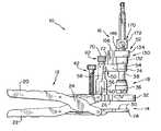
- FIG. 1is a side-elevational view of a patellar milling clamp according to the present invention
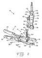
- FIG. 2is an exploded perspective view of the milling clamp shown in FIG. 1 ;
- FIG. 3is an exploded perspective view of the guide tower assembly portion of the milling clamp shown in the previous drawings;
- FIG. 4is perspective view of the cap for the guide tower
- FIG. 5is a cross-sectional view of the cap, taken along line 5 — 5 of FIG. 4 ;
- FIG. 6is a top view of the guide tower
- FIG. 7is an elevational view of one side of the guide tower
- FIG. 8is an elevational view of one end of the guide tower
- FIG. 9is another side elevational view of the guide tower, showing the side opposite the side shown in FIG. 7 ;
- FIG. 10is another end elevational view of the guide tower, showing the end opposite the end shown in FIG. 8 ;
- FIG. 11is an enlarged cross-sectional view of the milling tool stop in accordance with the present invention.
- Milling clamp 10generally includes a handle assembly 12 , a clamping assembly 14 and a milling tool guide tower assembly 16 . Milling clamp 10 operates in cooperation with a milling tool 18 during the performance of a milling procedure on a patella bone (not shown). Milling clamp 10 is constructed of surgical instrument quality materials, such that it may be cleaned and sterilized for repetitive use. It is readily disassembled, as will be described, so that it may be cleaned thoroughly between uses.
- Handle assembly 12includes an upper handle 20 and a lower handle 22 that are crossed with each other at an area 24 of crossed handles 20 and 22 .
- Clamping assembly 14includes an upper jaw assembly 26 detachably connected to lower handle 22 , and a lower jaw assembly 28 detachably connected to upper handle 20 .
- handle assembly 12 and clamping assembly 14have an appearance through connection area 24 to function similarly to that of pliers or scissors.
- a patella bonecan be clamped between upper jaw assembly 26 and lower jaw assembly 28 .
- lower jaw assembly 28may be provided with one or more prongs 30 , to partially embed in the patella bone, and prevent the bone from sliding relative to clamping assembly 14 .
- distal portions of jaw assemblies 26 and 28can be shaped advantageously to retain a patella bone between them.
- Upper jaw assembly 26includes a grater guide 32 detachably affixed thereto.
- Grater guide 32is essentially a ring, or annular body, best seen in FIG. 2 , sized to receive therein a grater (not shown) of milling tool 18 .
- Grater guide 32 and the grater (not shown)are sized such that the grater will slide through grater guide 32 , with minimal play such that the grater is precisely moved relative to a patellar bone affixed between upper jaw assembly 26 and lower jaw assembly 28 .
- the grater(not shown) is detachably affixed by a bayonet style coupling 36 on a drive shaft 38 of milling tool 18 .
- Milling tool 18further includes a pneumatic or other drive device (not shown) providing rotational power to shaft 38 , for rotating the grater to perform a milling procedure against a patella bone.
- a plurality of pins 40are used for securing upper jaw assembly 26 and lower jaw assembly 28 to lower handle 22 and upper handle 20 , respectively, and for securing grater guide 32 in upper jaw assembly 26 .
- pins 40are shown in FIG. 2 .
- Movement of jaw assemblies 26 and 28 toward or away from each othercan be performed by rotation of a driver 42 having threads 44 engaged with and extending through upper jaw assembly 26 .
- An outer end of driver 42includes a knob 46 to assist a user of clamp 10 in grasping and turning driver 42 .
- An inner end of driver 42is rotatably secured to, but not threadedly engaged with lower jaw assembly 28 .
- jaw assemblies 26 and 28can be caused to move toward or away from each other by rotation of driver 42 .
- Rotation of driver 42 in one directioncauses upper jaw assembly 26 to climb along threads 44 toward knob 46
- rotation of driver 42 in the opposite directioncauses upper jaw assembly 26 to descend on the threads toward lower jaw assembly 28 .
- driver 42holds jaw assemblies 26 and 28 in fixed spaced relation to each other.
- Guide tower assembly 16includes a guide tower 50 detachably secured to upper jaw assembly 26 .
- An adjustable milling depth control 52is operatively associated with and part of guide tower assembly 16 , for limiting the extent to which shaft 38 can be advanced towards a bone secured in clamping assembly 14 .
- Guide tower 50has a guide for shaft 38 in the nature of a guide bushing 54 that is essentially a cylindrical tube of proper size to slidably receive shaft 38 therein.
- Guide bushing 54is axially aligned with grater guide 32 , for guiding milling tool 18 linearly, toward and away from a patella held in clamping assembly 14 .
- Guide tower 50is detachably secured to upper jaw assembly 26 via a fork 56 extending downwardly from a leg 58 of guide tower 50 .
- Fork 56engages a post 60 extending upwardly from upper jaw assembly 26 .
- a screw 62extends through a hole 64 ( FIG. 3 ) in leg 58 , and includes threads 66 that engage threads in a hole (not shown) in post 60 .
- Screw 62further includes a head 70 having knurls or ridges 72 for grasping screw 62 such that screw 62 may be finger tightened in the hole 68 , to detachably secure guide tower 50 on upper jaw assembly 26 .
- post 60is square or rectangular in cross section, with at least two flat sides for engaging against flat sides of fork 56 , to prevent rotation of fork 56 on post 60 .
- Screw 62need be tightened only sufficiently to seat fork 56 on post 60 snuggly, but need not be overly tightened.
- Cooperative structures other than fork 56 and post 60can be used for accurately positioning tower 50 on upper jaw assembly 26 , as those skilled in the art will understand readily.
- Leg 58is connected to guide bushing 54 by an arm portion 74 of guide tower 50 .
- guide bushing 54 , arm 74 , leg 58 and fork 56are formed integrally as a monolithic body.
- Depth control 52is a cooperative assembly between structures of and on guide bushing 54 and structures on shaft 38 .
- Guide bushing 54includes a top end 90 and a bottom end 92 .
- a plurality of notches 94 , 96 , 98 and 100are provided extending downwardly from top end 90 at the outer surface of guide bushing 54 .
- guide bushing 54includes four notches 94 , 96 , 98 and 100 , but also may include fewer than four notches, or more than four notches.
- Each notch 94 , 96 , 98 and 100includes a floor 104 , 106 , 108 and 110 , respectively.
- Each floor 104 , 106 , 108 and 110is a preestablished different distance from top end 90 , thereby providing a plurality of different fixed elevations on guide bushing 54 .
- Each notch 94 , 96 , 98 and 100further includes a flattened face 114 , 116 , 118 and 120 , respectively, extending between floor 104 , 106 , 108 and 110 , respectively, and top end 90 .
- Notches 94 , 96 , 98 and 100are spaced from each other by lands 122 , 124 , 126 and 128 .
- Notches 94 and 96are adjacent each other, and separated by land 122 .
- Notches 96 and 98are adjacent each other, and separated by land 124 .
- Notches 98 and 100are adjacent each other, and separated by land 126 .
- Notches 94 and 100are adjacent each other, and separated by land 128 . As shown, notches 94 , 96 , 98 and 100 are spaced evenly around guide bushing 54 , but need not necessarily be evenly spaced.
- Depth control 52further includes a cap 130 having a cylindrical body 132 and a top 134 (FIGS. 4 and 5 ).
- An axial opening 136 through body 132is sufficiently large to allow cap 130 to slide over top end 90 of guide bushing 54 .
- Top 134includes a narrowed opening 138 sufficient for cap 130 to slide over shaft 38 , but not sufficiently large for top 134 to slide completely over guide bushing 54 .
- an indexing key 140extends downwardly from top 134 . Indexing key 140 has a width and depth to be received in any of notches 94 , 96 , 98 and 100 .
- a bottom surface 142( FIG.
- indexing key 140rests on any of floors 104 , 106 , 108 and 110 .
- the body of key 140and particularly an inner wall 144 thereof, extends upwardly from bottom surface 142 , along the respective face 114 , 116 , 118 or 120 of the notch 94 , 96 , 98 or 100 in which indexing key 140 is received.
- indexing key 140can be positioned in any of the notches 94 , 96 , 98 and 100 .
- an abutment surface 146 on top 134 of cap 130can be positioned at selective elevations with respect to guide bushing 54 .
- Abutment surface 146can be scribed or otherwise marked into quadrants 148 , 150 , 152 and 154 and provided with numerical markings indicating the milling depths when indexing key 140 is seated in a particular notch 94 , 96 , 98 or 100 .
- a post 156 having threads 158is secured in a threaded hole 160 of arm 74 (FIG. 3 ).
- An arrow, line or other indicator(not shown) is provided on post 156 to create a visual reference for selecting the desired position of cap 130 by aligning the proper one of quadrants 148 , 150 , 152 and 154 with post 156 .
- Depth control 52further includes a stop ring 170 secured on shaft 38 .
- a sleeve 172 slidable on shaft 38is provided with a trigger button 174 having a hole 176 .
- a curved spring 178is secured with trigger button 174 via a pin 180 .
- an axial opening 182 in sleeve 172can be offset slightly from hole 176 in button 174 , to provide a wedging engagement between stop ring 170 and shaft 38 .
- trigger button 174By depressing trigger button 174 , axial opening 182 and hole 176 are aligned, allowing shaft 38 to slide therethrough. In this manner, stop ring 170 can be adjusted along shaft 38 and secured on shaft 38 at a desired position.
- a patella boneis placed between upper jaw assembly 26 and lower jaw assembly 28 , and is clamped there between by rotating driver 42 to move jaw assemblies 26 and 28 toward each other until the patella is clamped firmly.
- a grater(not shown) is attached to shaft 38 , with shaft 38 extended through guide bushing 54 .
- Guide tower 50is attached to upper jaw assembly 26 by engaging post 60 of upperjaw assembly 26 with fork 56 of guide tower 50 .
- Screw 62is inserted through post 60 , with threads 66 thereof secured and tightened in post 60 .
- the height of faces 114 , 116 , 118 and 120 between floors 104 , 106 , 108 and 110 , respectively, and top end 90are selected to provide a zero penetration depth, and common required milling depths for standard patellar implants used.
- the shallowest of notches 94 , 96 , 98 and 100is provided as a zero depth notch.
- the remaining notches 96 , 98 and 100are provided at common milling depths deeper than the zero notch 94 , for example depths of 7, 8 or 9 millimeters below floor 104 of notch 94 .
- Cap 130is rotated on guide bushing 54 until indexing key 140 is aligned with the shallowest notch, notch 94 as shown. Cap 130 is lowered until bottom surface 142 of indexing key 140 is positioned against floor 104 of notch 94 . Abutment surface 146 of cap 130 is then at the zero position. Adjustment is completed by advancing milling tool 18 until the grater (not shown) is positioned against the patella bone, and stop ring 170 is slid downwardly on shaft 38 to abut abutment surface 146 .
- shaft 38is retracted slightly, without moving stop ring 170 relative to the position thereof on shaft 38 .
- Cap 130lifted and rotated as necessary to position indexing key 140 in the required one of notches 96 , 98 and 100 corresponding to the desired milling depth.
- abutment surface 140is lowered relative to the zero position established earlier, and the distance of separation is equal to the difference in height of the one of faces 116 , 118 and 120 for the one of notches 96 , 98 and 100 selected and the height of face 114 for zero notch 94 .
- stop ring 170is separated from abutment surface 146 by the selected milling depth or penetration.
- shaft 38slides in guide bushing 54 and the grater (not shown) slides in grater guide 32 downwardly until stop ring 170 abuts abutment surface 146 . Further advancement of shaft 38 toward lower jaw assembly 28 is thereby prevented.
- the difference between the height of face 114 and the height of face 116 , 118 or 120 for the selected notch 96 , 98 or 100determines the axial distance which shaft 38 can be advanced, and thereby determines the depth of the milling process in the patella bone clamped between upper jaw assembly 26 and lower jaw assembly 28 .
- the depth to which milling occursis the same regardless of the original thickness of the patella bone being milled.
- a predetermined precise depthcan be achieved, as necessary, for the patellar implant being used.
- Adjustment of the depth controlis easily performed by lifting and rotating cap 130 relative to guide bushing 54 .
- indexing key 140is properly positioned in the selected one of notches 94 , 96 , 98 and 100 , with bottom surface 142 of key 140 positioned on the selected one of floors 104 , 106 , 108 and 110 and inner wall 144 of key 140 positioned along the selected one of faces 114 , 116 , 118 and 120 , cap 130 cannot be accidentally rotated and displaced, without raising cap 130 relative to guide bushing 54 and rotating cap 130 through a quarter turn.
- depth control 52stays firmly in place to provide precise, accurate milling depth control.
- milling tool 18can comprise different size and types of graters, or other devices, such as, for example, a drill; and guide 32 can comprise a drill guide for accurately positioning anchor holes to receive anchor pins of an implant.
- Jaw assemblies 26 and 28 of clamping assembly 14can be changed with modular inserts to receive different size patellae, or to perform cementing or other clamping procedures.
- Milling clamp 10is lightweight and versatile.
Landscapes
- Health & Medical Sciences (AREA)
- Surgery (AREA)
- Life Sciences & Earth Sciences (AREA)
- Biomedical Technology (AREA)
- Medical Informatics (AREA)
- Orthopedic Medicine & Surgery (AREA)
- Oral & Maxillofacial Surgery (AREA)
- Engineering & Computer Science (AREA)
- Dentistry (AREA)
- Heart & Thoracic Surgery (AREA)
- Nuclear Medicine, Radiotherapy & Molecular Imaging (AREA)
- Molecular Biology (AREA)
- Animal Behavior & Ethology (AREA)
- General Health & Medical Sciences (AREA)
- Public Health (AREA)
- Veterinary Medicine (AREA)
- Surgical Instruments (AREA)
Abstract
Description
Claims (21)
Priority Applications (1)
| Application Number | Priority Date | Filing Date | Title |
|---|---|---|---|
| US10/234,916US6866667B2 (en) | 2002-09-03 | 2002-09-03 | Patellar milling clamp |
Applications Claiming Priority (1)
| Application Number | Priority Date | Filing Date | Title |
|---|---|---|---|
| US10/234,916US6866667B2 (en) | 2002-09-03 | 2002-09-03 | Patellar milling clamp |
Publications (2)
| Publication Number | Publication Date |
|---|---|
| US20040087961A1 US20040087961A1 (en) | 2004-05-06 |
| US6866667B2true US6866667B2 (en) | 2005-03-15 |
Family
ID=32174471
Family Applications (1)
| Application Number | Title | Priority Date | Filing Date |
|---|---|---|---|
| US10/234,916Expired - LifetimeUS6866667B2 (en) | 2002-09-03 | 2002-09-03 | Patellar milling clamp |
Country Status (1)
| Country | Link |
|---|---|
| US (1) | US6866667B2 (en) |
Cited By (30)
| Publication number | Priority date | Publication date | Assignee | Title |
|---|---|---|---|---|
| EP1911407A1 (en) | 2006-10-12 | 2008-04-16 | WALDEMAR LINK GmbH & Co. KG | Modular patellar resection instrument |
| US20080177394A1 (en)* | 2006-10-18 | 2008-07-24 | Howmedica Osteonics Corp. | Mis patellar preparation |
| US20080300689A1 (en)* | 2006-01-23 | 2008-12-04 | Mc Kinnon Brian W | Patellar Components |
| US20090088767A1 (en)* | 2007-09-27 | 2009-04-02 | Depuy Products, Inc. | Guide assembly for use in a medical procedure |
| USD666720S1 (en) | 2011-06-30 | 2012-09-04 | Depuy Products, Inc. | Patella resection guide |
| USD666721S1 (en) | 2011-06-30 | 2012-09-04 | Depuy Products, Inc. | Patella resection guide |
| USD667110S1 (en) | 2011-06-30 | 2012-09-11 | Depuy Products, Inc. | Multifunctional handle |
| USD667953S1 (en)* | 2011-06-30 | 2012-09-25 | Depuy Products, Inc. | Combination patella drill guide and clamp |
| USD679395S1 (en) | 2011-06-30 | 2013-04-02 | Depuy (Ireland) | Combination patella clamp and drill guide |
| US8821501B2 (en) | 2010-09-24 | 2014-09-02 | Depuy (Ireland) | Patella resectioning guide and assembly |
| US8915923B2 (en) | 2011-09-28 | 2014-12-23 | Depuy (Ireland) | Patella resection assembly |
| US8945135B2 (en) | 2011-02-14 | 2015-02-03 | Michael D. Ries | Patellar prostheses and instrumentation |
| US8951262B2 (en) | 2011-06-30 | 2015-02-10 | Depuy (Ireland) | Patella clamp and drill guide surgical instrument |
| US8968321B2 (en) | 2011-06-30 | 2015-03-03 | Depuy (Ireland) | Patella resection guide with locating features and method of using the same |
| US8979854B2 (en) | 2011-06-30 | 2015-03-17 | Depuy (Ireland) | Patella orthopaedic surgical instrument assembly |
| US8986306B2 (en) | 2011-06-30 | 2015-03-24 | Depuy (Ireland) | Patella orthopaedic surgical method |
| US8998912B2 (en) | 2011-09-28 | 2015-04-07 | Depuy (Ireland) | Clamping patella drill guide |
| US8998913B2 (en) | 2011-09-28 | 2015-04-07 | Depuy (Ireland) | Patella resection assembly |
| US9078676B2 (en) | 2011-09-28 | 2015-07-14 | Depuy (Ireland) | Patella drilling system |
| US9078772B2 (en) | 2011-09-28 | 2015-07-14 | Depuy (Ireland) | Rotatable patella drill guide |
| US9554813B2 (en) | 2012-09-28 | 2017-01-31 | Depuy Ireland Unlimited Company | Patella drill guide and trial surgical instrument |
| US9675399B2 (en) | 2011-02-14 | 2017-06-13 | Michael D. Ries | Patient specific implants and instrumentation for patellar prostheses |
| US20170245867A1 (en)* | 2014-10-24 | 2017-08-31 | Aston Medical | Device for the preparation of a patella for the implementation of a patellar implant |
| US10034679B1 (en)* | 2017-10-31 | 2018-07-31 | Boyer Anderson, LLC | Artificial prosthesis installation clamp and method |
| US10085758B2 (en) | 2012-09-28 | 2018-10-02 | Depuy Ireland Unlimited Company | Patella drill guide and trial surgical instrument having an alignment bore formed therein and method of using the same |
| US10172630B2 (en) | 2016-05-19 | 2019-01-08 | Medos International Sarl | Drill guide with adjustable stop |
| US10278714B2 (en) | 2015-03-27 | 2019-05-07 | Depuy Ireland Unlimted Company | Orthopaedic surgical instrument system for implanting a prosthetic patella component and method of use |
| US10335163B2 (en) | 2013-03-05 | 2019-07-02 | Depuy Ireland Unlimited Company | Polymer 4-in-2 femoral cutting instrument having separable A/P and chamfer cutting blocks |
| US10987116B2 (en) | 2017-12-15 | 2021-04-27 | Medos International Sarl | Adjustable drill guides and related methods |
| US12076025B2 (en) | 2022-05-11 | 2024-09-03 | DePuy Synthes Products, Inc. | Polymer cutting block |
Families Citing this family (1)
| Publication number | Priority date | Publication date | Assignee | Title |
|---|---|---|---|---|
| USD991451S1 (en)* | 2020-10-27 | 2023-07-04 | Depuy Ireland Unlimited Company | Patella clamp |
Citations (24)
| Publication number | Priority date | Publication date | Assignee | Title |
|---|---|---|---|---|
| US2291413A (en) | 1941-06-13 | 1942-07-28 | John R Siebrandt | Bone clamping and wire adjusting means |
| US2427128A (en) | 1946-01-28 | 1947-09-09 | Zimmer Mfg Company | Surgical bone clamp |
| US2698483A (en) | 1953-01-12 | 1955-01-04 | Berkowitz Julius | Interspatial dental tooth clamp |
| US3037405A (en) | 1959-08-24 | 1962-06-05 | Francis W Zimmerman | Micrometer depth gage |
| US3126767A (en) | 1964-03-31 | sawyer | ||
| US3724963A (en) | 1971-09-20 | 1973-04-03 | M Stadtmiller | Quill stop and gauge therefor |
| US3979165A (en) | 1975-05-22 | 1976-09-07 | Pyle Arnold S | Drill guide |
| US4312337A (en) | 1980-09-08 | 1982-01-26 | Donohue Brian T | Cannula and drill guide apparatus |
| USD273326S (en) | 1981-02-27 | 1984-04-03 | Ab Stille-Werner | Surgical instrument for guiding a drill bit for drilling through bone sections |
| US4444180A (en) | 1982-03-01 | 1984-04-24 | Aktiebolaget Stille-Werner | Surgical instrument for engaging a bony part of the human body and guiding a drill bit into a specific location in the bony part |
| US4565192A (en) | 1984-04-12 | 1986-01-21 | Shapiro James A | Device for cutting a patella and method therefor |
| US4586497A (en) | 1983-10-31 | 1986-05-06 | David J. Dapra | Drill fixation device and method for vertebra cutting |
| US4633862A (en) | 1985-05-30 | 1987-01-06 | Petersen Thomas D | Patellar resection sawguide |
| US4706660A (en) | 1985-05-30 | 1987-11-17 | Petersen Thomas D | Patellar clamp |
| US4736737A (en) | 1986-03-31 | 1988-04-12 | William Fargie | Tibial cutting jig |
| US4750481A (en) | 1984-04-16 | 1988-06-14 | Reese H William | Osteotomy appliances and method |
| US4952213A (en) | 1989-02-03 | 1990-08-28 | Boehringer Mannheim Corporation | Tibial cutting guide |
| US5002547A (en) | 1987-02-07 | 1991-03-26 | Pfizer Hospital Products Group, Inc. | Apparatus for knee prosthesis |
| US5021055A (en) | 1990-09-19 | 1991-06-04 | Intermedics Orthopedics, Inc. | Patellar clamp and surgical saw guide |
| US5129907A (en) | 1990-12-10 | 1992-07-14 | Zimmer, Inc. | Patellar clamp and reamer with adjustable stop |
| US5486177A (en)* | 1994-12-20 | 1996-01-23 | Intermedics Orthopedics, Inc. | Patella planer with adjustable stop |
| US5536271A (en)* | 1994-06-02 | 1996-07-16 | Depuy, Inc. | Patella reaming system |
| US5716360A (en)* | 1995-06-30 | 1998-02-10 | U.S. Medical Products | Patella recession instrument and method for anatomically-shaped patellar prostheses |
| US6277121B1 (en)* | 1998-09-09 | 2001-08-21 | Brian D. Burkinshaw | Patella reaming system |
Family Cites Families (1)
| Publication number | Priority date | Publication date | Assignee | Title |
|---|---|---|---|---|
| DE73326C (en)* | Firma CARL THIEL & SÖHNE in Lübeck | Closing device for vessels for sterilization |
- 2002
- 2002-09-03USUS10/234,916patent/US6866667B2/ennot_activeExpired - Lifetime
Patent Citations (24)
| Publication number | Priority date | Publication date | Assignee | Title |
|---|---|---|---|---|
| US3126767A (en) | 1964-03-31 | sawyer | ||
| US2291413A (en) | 1941-06-13 | 1942-07-28 | John R Siebrandt | Bone clamping and wire adjusting means |
| US2427128A (en) | 1946-01-28 | 1947-09-09 | Zimmer Mfg Company | Surgical bone clamp |
| US2698483A (en) | 1953-01-12 | 1955-01-04 | Berkowitz Julius | Interspatial dental tooth clamp |
| US3037405A (en) | 1959-08-24 | 1962-06-05 | Francis W Zimmerman | Micrometer depth gage |
| US3724963A (en) | 1971-09-20 | 1973-04-03 | M Stadtmiller | Quill stop and gauge therefor |
| US3979165A (en) | 1975-05-22 | 1976-09-07 | Pyle Arnold S | Drill guide |
| US4312337A (en) | 1980-09-08 | 1982-01-26 | Donohue Brian T | Cannula and drill guide apparatus |
| USD273326S (en) | 1981-02-27 | 1984-04-03 | Ab Stille-Werner | Surgical instrument for guiding a drill bit for drilling through bone sections |
| US4444180A (en) | 1982-03-01 | 1984-04-24 | Aktiebolaget Stille-Werner | Surgical instrument for engaging a bony part of the human body and guiding a drill bit into a specific location in the bony part |
| US4586497A (en) | 1983-10-31 | 1986-05-06 | David J. Dapra | Drill fixation device and method for vertebra cutting |
| US4565192A (en) | 1984-04-12 | 1986-01-21 | Shapiro James A | Device for cutting a patella and method therefor |
| US4750481A (en) | 1984-04-16 | 1988-06-14 | Reese H William | Osteotomy appliances and method |
| US4633862A (en) | 1985-05-30 | 1987-01-06 | Petersen Thomas D | Patellar resection sawguide |
| US4706660A (en) | 1985-05-30 | 1987-11-17 | Petersen Thomas D | Patellar clamp |
| US4736737A (en) | 1986-03-31 | 1988-04-12 | William Fargie | Tibial cutting jig |
| US5002547A (en) | 1987-02-07 | 1991-03-26 | Pfizer Hospital Products Group, Inc. | Apparatus for knee prosthesis |
| US4952213A (en) | 1989-02-03 | 1990-08-28 | Boehringer Mannheim Corporation | Tibial cutting guide |
| US5021055A (en) | 1990-09-19 | 1991-06-04 | Intermedics Orthopedics, Inc. | Patellar clamp and surgical saw guide |
| US5129907A (en) | 1990-12-10 | 1992-07-14 | Zimmer, Inc. | Patellar clamp and reamer with adjustable stop |
| US5536271A (en)* | 1994-06-02 | 1996-07-16 | Depuy, Inc. | Patella reaming system |
| US5486177A (en)* | 1994-12-20 | 1996-01-23 | Intermedics Orthopedics, Inc. | Patella planer with adjustable stop |
| US5716360A (en)* | 1995-06-30 | 1998-02-10 | U.S. Medical Products | Patella recession instrument and method for anatomically-shaped patellar prostheses |
| US6277121B1 (en)* | 1998-09-09 | 2001-08-21 | Brian D. Burkinshaw | Patella reaming system |
Non-Patent Citations (8)
| Title |
|---|
| Biomet Inc. AGC-Total Knee System: Patellar Instrumentation 1990. |
| Depuy-AMK Total Knee System Design Rationale and Surgical Procedure-Engh et al.-3 pages including p25. |
| Dow Corning Wright-"We-re Pushing All the Wright Buttons." |
| Dow Corning Wright-Whiteside ORTHOLOC II Total Knee System: Surgical Technique Patella Recessing-pp. 1-5. |
| Intermedics Orthopedics, Inc.-The Intermedics Natural-Knee System-Hoffman-pp. 23-24. |
| Richards Tricon Total Knee System-Tricon-M With Pro-Fit Surgical Procedures-4 pages including pp. 14-15. |
| Richards-Genesis Total Knee System: Addressing the Unexpected-Cruciate-Retaining Primary Technique-pp. 21-23, 34. |
| Richards-pp. 37-38-Various Patellar Instruments. |
Cited By (50)
| Publication number | Priority date | Publication date | Assignee | Title |
|---|---|---|---|---|
| US8142509B2 (en) | 2006-01-23 | 2012-03-27 | Smith & Nephew, Inc. | Patellar components |
| US20080300689A1 (en)* | 2006-01-23 | 2008-12-04 | Mc Kinnon Brian W | Patellar Components |
| EP1911407A1 (en) | 2006-10-12 | 2008-04-16 | WALDEMAR LINK GmbH & Co. KG | Modular patellar resection instrument |
| WO2008043410A1 (en)* | 2006-10-12 | 2008-04-17 | Waldemar Link Gmbh & Co. Kg | Modular patella instrument |
| US20100030223A1 (en)* | 2006-10-12 | 2010-02-04 | Waldemar Link Gmbh & Co., Kg | Modular patella instrument |
| CN101522114B (en)* | 2006-10-12 | 2011-10-19 | 沃尔德马连接两合公司 | Modular patella instrument |
| US20080177394A1 (en)* | 2006-10-18 | 2008-07-24 | Howmedica Osteonics Corp. | Mis patellar preparation |
| US20100160915A1 (en)* | 2006-10-18 | 2010-06-24 | Howmedica Osteonics Corp. | Mis patellar preparation |
| US7758651B2 (en) | 2006-10-18 | 2010-07-20 | Howmedica Osteonics Corp. | Mis patellar preparation |
| US20090088767A1 (en)* | 2007-09-27 | 2009-04-02 | Depuy Products, Inc. | Guide assembly for use in a medical procedure |
| US8808300B2 (en)* | 2007-09-27 | 2014-08-19 | Biomet C.V. | Guide assembly for use in a medical procedure |
| US8821501B2 (en) | 2010-09-24 | 2014-09-02 | Depuy (Ireland) | Patella resectioning guide and assembly |
| US8945135B2 (en) | 2011-02-14 | 2015-02-03 | Michael D. Ries | Patellar prostheses and instrumentation |
| US9675399B2 (en) | 2011-02-14 | 2017-06-13 | Michael D. Ries | Patient specific implants and instrumentation for patellar prostheses |
| USD667110S1 (en) | 2011-06-30 | 2012-09-11 | Depuy Products, Inc. | Multifunctional handle |
| USD667953S1 (en)* | 2011-06-30 | 2012-09-25 | Depuy Products, Inc. | Combination patella drill guide and clamp |
| USD666721S1 (en) | 2011-06-30 | 2012-09-04 | Depuy Products, Inc. | Patella resection guide |
| USD679395S1 (en) | 2011-06-30 | 2013-04-02 | Depuy (Ireland) | Combination patella clamp and drill guide |
| USD666720S1 (en) | 2011-06-30 | 2012-09-04 | Depuy Products, Inc. | Patella resection guide |
| US8951262B2 (en) | 2011-06-30 | 2015-02-10 | Depuy (Ireland) | Patella clamp and drill guide surgical instrument |
| US8968321B2 (en) | 2011-06-30 | 2015-03-03 | Depuy (Ireland) | Patella resection guide with locating features and method of using the same |
| US8979854B2 (en) | 2011-06-30 | 2015-03-17 | Depuy (Ireland) | Patella orthopaedic surgical instrument assembly |
| US8986306B2 (en) | 2011-06-30 | 2015-03-24 | Depuy (Ireland) | Patella orthopaedic surgical method |
| US9414851B2 (en) | 2011-06-30 | 2016-08-16 | Depuy (Ireland) | Patella clamp and drill guide surgical instrument and method of use |
| US8998913B2 (en) | 2011-09-28 | 2015-04-07 | Depuy (Ireland) | Patella resection assembly |
| US8915923B2 (en) | 2011-09-28 | 2014-12-23 | Depuy (Ireland) | Patella resection assembly |
| US9078772B2 (en) | 2011-09-28 | 2015-07-14 | Depuy (Ireland) | Rotatable patella drill guide |
| US9295483B2 (en) | 2011-09-28 | 2016-03-29 | Depuy (Ireland) | Rotatable patella drill guide |
| US8998912B2 (en) | 2011-09-28 | 2015-04-07 | Depuy (Ireland) | Clamping patella drill guide |
| US9078676B2 (en) | 2011-09-28 | 2015-07-14 | Depuy (Ireland) | Patella drilling system |
| US11109873B2 (en) | 2012-09-28 | 2021-09-07 | Depuy Ireland Unlimited Company | Patella drill guide and trial surgical instrument system and method of using the same |
| US9554813B2 (en) | 2012-09-28 | 2017-01-31 | Depuy Ireland Unlimited Company | Patella drill guide and trial surgical instrument |
| US11925365B2 (en) | 2012-09-28 | 2024-03-12 | Depuy Ireland Unlimited Company | Patella drill guide and trial surgical instrument |
| US9855065B2 (en) | 2012-09-28 | 2018-01-02 | Depuy Ireland Unlimited Company | Orthopaedic surgical instrument assembly for implanting a prosthetic patella component |
| US9700330B2 (en) | 2012-09-28 | 2017-07-11 | Depuy Ireland Unlimited Company | Method for surgically implanting a prosthetic patella component |
| US10085758B2 (en) | 2012-09-28 | 2018-10-02 | Depuy Ireland Unlimited Company | Patella drill guide and trial surgical instrument having an alignment bore formed therein and method of using the same |
| US10335163B2 (en) | 2013-03-05 | 2019-07-02 | Depuy Ireland Unlimited Company | Polymer 4-in-2 femoral cutting instrument having separable A/P and chamfer cutting blocks |
| US11234711B2 (en) | 2013-03-05 | 2022-02-01 | Depuy Ireland Unlimited Company | Polymer 4-in-2 femoral cutting instrument having separable A/P and chamfer cutting blocks |
| US20170245867A1 (en)* | 2014-10-24 | 2017-08-31 | Aston Medical | Device for the preparation of a patella for the implementation of a patellar implant |
| US11304711B2 (en) | 2015-03-27 | 2022-04-19 | Depuy Ireland Unlimited Company | Orthopaedic surgical instrument system for implanting a prosthetic patella component and method of use |
| US10278714B2 (en) | 2015-03-27 | 2019-05-07 | Depuy Ireland Unlimted Company | Orthopaedic surgical instrument system for implanting a prosthetic patella component and method of use |
| US12156663B2 (en) | 2015-03-27 | 2024-12-03 | Depuy Ireland Unlimited Company | Orthopaedic surgical instrument system for implanting a prosthetic patella component and method of use |
| US12167862B2 (en) | 2015-03-27 | 2024-12-17 | Depuy Ireland Unlimited Company | Orthopaedic surgical instrument system for implanting a prosthetic patella component and method of use |
| US10945744B2 (en) | 2016-05-19 | 2021-03-16 | Medos International Sarl | Drill guide with adjustable stop |
| US10172630B2 (en) | 2016-05-19 | 2019-01-08 | Medos International Sarl | Drill guide with adjustable stop |
| US10799254B2 (en)* | 2017-10-31 | 2020-10-13 | Boyer Anderson, LLC | Artificial prosthesis installation clamp and method |
| US10034679B1 (en)* | 2017-10-31 | 2018-07-31 | Boyer Anderson, LLC | Artificial prosthesis installation clamp and method |
| US20190125372A1 (en)* | 2017-10-31 | 2019-05-02 | Boyer Anderson, LLC | Artificial Prosthesis Installation Clamp and Method |
| US10987116B2 (en) | 2017-12-15 | 2021-04-27 | Medos International Sarl | Adjustable drill guides and related methods |
| US12076025B2 (en) | 2022-05-11 | 2024-09-03 | DePuy Synthes Products, Inc. | Polymer cutting block |
Also Published As
| Publication number | Publication date |
|---|---|
| US20040087961A1 (en) | 2004-05-06 |
Similar Documents
| Publication | Publication Date | Title |
|---|---|---|
| US6866667B2 (en) | Patellar milling clamp | |
| US5575793A (en) | Patella clamp apparatus | |
| US4627425A (en) | Osteotomy appliances and method | |
| US7344540B2 (en) | Patella resection guide | |
| CA2050808C (en) | Patellar clamp and reamer with adjustable stop | |
| US8216242B2 (en) | Modular patella instrument | |
| US6277121B1 (en) | Patella reaming system | |
| US7608079B1 (en) | Unicondylar knee apparatus and system | |
| EP1732452B1 (en) | Adjustable depth drill bit | |
| EP1911407B1 (en) | Modular patellar resection instrument | |
| US4750481A (en) | Osteotomy appliances and method | |
| KR101169809B1 (en) | Quick-release drill guide assembly for bone plate | |
| US3867932A (en) | Assembly for inserting rigid shafts into fractured bones | |
| US20050240196A1 (en) | Apparatus for use in orthopaedic surgery | |
| US4028810A (en) | Root canal file | |
| JPH09224952A (en) | Patella cutting apparatus | |
| CZ302276B6 (en) | Security device comprising a stop member for drilling tool used in particular in dental surgery and device for pre-calibration and storage of drilling depth | |
| US11918490B2 (en) | Meniscal transplant system | |
| KR20060135633A (en) | Surgical Drill Guides | |
| JP2014131735A (en) | Trajectory guide | |
| JPH08191841A (en) | Orthopedic alignment guide and resection guide | |
| US20060229626A1 (en) | In-line milling system | |
| US10758319B2 (en) | Surgical dental tool | |
| MXPA05010453A (en) | Tool and method for scribing longitudinal lines on a cylindrical rod. | |
| JP2846347B2 (en) | Artificial patella placement device |
Legal Events
| Date | Code | Title | Description |
|---|---|---|---|
| AS | Assignment | Owner name:OTHY, INC., INDIANA Free format text:ASSIGNMENT OF ASSIGNORS INTEREST;ASSIGNORS:WOOD, STEVEN R.;MENDENHALL, BRYAN C.;SALYER, PAUL E.;REEL/FRAME:013266/0656 Effective date:20020626 | |
| AS | Assignment | Owner name:WACHOVIA BANK, NATIONAL ASSOCIATION, NORTH CAROLIN Free format text:SECURITY AGREEMENT;ASSIGNOR:SYMMETRY MEDICAL USA INC.;REEL/FRAME:014201/0877 Effective date:20030611 | |
| AS | Assignment | Owner name:SYMMETRY MEDICAL USA, INC., INDIANA Free format text:MERGER;ASSIGNOR:OTHY, INC.;REEL/FRAME:014939/0818 Effective date:20011213 | |
| AS | Assignment | Owner name:WACHOVIA BANK, NATIONAL ASSOCIATION, NORTH CAROLIN Free format text:SECURITY AGREEMENT;ASSIGNORS:SYMMETRY MEDICAL INC.;SYMMETRY MEDICAL USA INC., A DELAWARE CORPORATION;REEL/FRAME:015460/0042 Effective date:20041214 | |
| AS | Assignment | Owner name:SYMMETRY MEDICAL INC., INDIANA Free format text:RELEASE OF SECURITY INTEREST;ASSIGNOR:WACHOVIA BANK, NATIONAL ASSOCIATION;REEL/FRAME:015552/0866 Effective date:20041214 Owner name:SYMMETRY MEDICAL USA INC., INDIANA Free format text:RELEASE OF SECURITY INTEREST;ASSIGNOR:WACHOVIA BANK, NATIONAL ASSOCIATION;REEL/FRAME:015552/0866 Effective date:20041214 | |
| STCF | Information on status: patent grant | Free format text:PATENTED CASE | |
| CC | Certificate of correction | ||
| FEPP | Fee payment procedure | Free format text:PAT HOLDER NO LONGER CLAIMS SMALL ENTITY STATUS, ENTITY STATUS SET TO UNDISCOUNTED (ORIGINAL EVENT CODE: STOL); ENTITY STATUS OF PATENT OWNER: LARGE ENTITY | |
| FPAY | Fee payment | Year of fee payment:4 | |
| AS | Assignment | Owner name:JPMORGAN CHASE BANK, N.A., AS ADMINISTRATIVE AGENT Free format text:SECURITY AGREEMENT;ASSIGNOR:SYMMETRY MEDICAL USA INC.;REEL/FRAME:025350/0069 Effective date:20101103 | |
| AS | Assignment | Owner name:SYMMETRY MEDICAL USA, INC., INDIANA Free format text:RELEASE OF SECURITY INTEREST RECORDED AT REEL/FRAME 15460/042 AND 17766/615;ASSIGNOR:WELLS FARGO BANK, NATIONAL ASSOCIATION (AS SUCCESSOR BY MERGER TO WACHOVIA BANK, NATIONAL ASSOCIATION);REEL/FRAME:025627/0610 Effective date:20101227 | |
| AS | Assignment | Owner name:SYMMETRY MEDICAL MANUFACTURING, INC., INDIANA Free format text:ASSIGNMENT OF ASSIGNORS INTEREST;ASSIGNOR:SYMMETRY MEDICAL USA, INC.;REEL/FRAME:027178/0427 Effective date:20111103 | |
| FPAY | Fee payment | Year of fee payment:8 | |
| AS | Assignment | Owner name:SYMMETRY MEDICAL USA INC., INDIANA Free format text:RELEASE BY SECURED PARTY;ASSIGNOR:JPMORGAN CHASE BANK, N.A., AS ADMINISTRATIVE AGENT;REEL/FRAME:034539/0521 Effective date:20141205 | |
| AS | Assignment | Owner name:CREDIT SUISSE AG, CAYMAN ISLANDS BRANCH, AS AGENT, Free format text:SECOND LIEN INTELLECTUAL PROPERTY SECURITY AGREEMENT;ASSIGNOR:SYMMETRY MEDICAL MANUFACTURING INC.;REEL/FRAME:034546/0049 Effective date:20141205 Owner name:CREDIT SUISSE AG, CAYMAN ISLANDS BRANCH, AS AGENT, Free format text:FIRST LIEN INTELLECTUAL PROPERTY SECURITY AGREEMENT;ASSIGNOR:SYMMETRY MEDICAL MANUFACTURING INC.;REEL/FRAME:034546/0001 Effective date:20141205 | |
| FPAY | Fee payment | Year of fee payment:12 | |
| AS | Assignment | Owner name:WELLS FARGO BANK, NATIONAL ASSOCIATION, AS ADMINIS Free format text:SECURITY INTEREST;ASSIGNORS:TECOMET INC.;SYMMETRY MEDICAL INC.;SYMMETRY MEDICAL MANUFACTURING INC.;REEL/FRAME:042380/0915 Effective date:20170501 Owner name:WELLS FARGO BANK, NATIONAL ASSOCIATION, AS ADMINISTRATIVE AGENT, CALIFORNIA Free format text:SECURITY INTEREST;ASSIGNORS:TECOMET INC.;SYMMETRY MEDICAL INC.;SYMMETRY MEDICAL MANUFACTURING INC.;REEL/FRAME:042380/0915 Effective date:20170501 | |
| AS | Assignment | Owner name:JEFFERIES FINANCE LLC, AS COLLATERAL AGENT, NEW YO Free format text:SECURITY AGREEMENT;ASSIGNORS:TECOMET INC.;SYMMETRY MEDICAL MANUFACTURING INC.;SYMMETRY MEDICAL INC.;REEL/FRAME:042386/0154 Effective date:20170501 Owner name:TECOMET INC., MASSACHUSETTS Free format text:RELEASE OF SECOND LIEN SECURITY INTEREST;ASSIGNOR:CREDIT SUISSE AG, CAYMAN ISLANDS BRANCH;REEL/FRAME:042386/0407 Effective date:20170501 Owner name:SYMMETRY MEDICAL MANUFACTURING INC., NEW HAMPSHIRE Free format text:RELEASE OF SECOND LIEN SECURITY INTEREST;ASSIGNOR:CREDIT SUISSE AG, CAYMAN ISLANDS BRANCH;REEL/FRAME:042386/0407 Effective date:20170501 Owner name:SYMMETRY MEDICAL MANUFACTURING INC., NEW HAMPSHIRE Free format text:RELEASE OF FIRST LIEN SECURITY INTEREST;ASSIGNOR:CREDIT SUISSE AG, CAYMAN ISIANDS BRANCH;REEL/FRAME:042386/0363 Effective date:20170501 Owner name:SYMMETRY MEDICAL INC., NEW YORK Free format text:RELEASE OF FIRST LIEN SECURITY INTEREST;ASSIGNOR:CREDIT SUISSE AG, CAYMAN ISIANDS BRANCH;REEL/FRAME:042386/0363 Effective date:20170501 Owner name:SYMMETRY MEDICAL INC., NEW YORK Free format text:RELEASE OF SECOND LIEN SECURITY INTEREST;ASSIGNOR:CREDIT SUISSE AG, CAYMAN ISLANDS BRANCH;REEL/FRAME:042386/0407 Effective date:20170501 Owner name:NEIPAL ENTERPRISES, INC., COLORADO Free format text:RELEASE OF FIRST LIEN SECURITY INTEREST;ASSIGNOR:CREDIT SUISSE AG, CAYMAN ISIANDS BRANCH;REEL/FRAME:042386/0363 Effective date:20170501 Owner name:MOUNTAINSIDE MEDICAL COLORADO, LLC, COLORADO Free format text:RELEASE OF SECOND LIEN SECURITY INTEREST;ASSIGNOR:CREDIT SUISSE AG, CAYMAN ISLANDS BRANCH;REEL/FRAME:042386/0407 Effective date:20170501 Owner name:NEIPAL ENTERPRISES, INC., COLORADO Free format text:RELEASE OF SECOND LIEN SECURITY INTEREST;ASSIGNOR:CREDIT SUISSE AG, CAYMAN ISLANDS BRANCH;REEL/FRAME:042386/0407 Effective date:20170501 Owner name:TECOMET INC., MASSACHUSETTS Free format text:RELEASE OF FIRST LIEN SECURITY INTEREST;ASSIGNOR:CREDIT SUISSE AG, CAYMAN ISIANDS BRANCH;REEL/FRAME:042386/0363 Effective date:20170501 Owner name:MOUNTAINSIDE MEDICAL COLORADO, LLC, COLORADO Free format text:RELEASE OF FIRST LIEN SECURITY INTEREST;ASSIGNOR:CREDIT SUISSE AG, CAYMAN ISIANDS BRANCH;REEL/FRAME:042386/0363 Effective date:20170501 Owner name:JEFFERIES FINANCE LLC, AS COLLATERAL AGENT, NEW YORK Free format text:SECURITY AGREEMENT;ASSIGNORS:TECOMET INC.;SYMMETRY MEDICAL MANUFACTURING INC.;SYMMETRY MEDICAL INC.;REEL/FRAME:042386/0154 Effective date:20170501 | |
| AS | Assignment | Owner name:PNC BANK, NATIONAL ASSOCIATION, NEW YORK Free format text:SECURITY INTEREST;ASSIGNORS:TECOMET INC.;SYMMETRY MEDICAL MANUFACTURING INC.;SYMMETRY MEDICAL INC.;REEL/FRAME:064236/0110 Effective date:20230707 Owner name:SYMMETRY MEDICAL INC., INDIANA Free format text:RELEASE BY SECURED PARTY;ASSIGNOR:WELLS FARGO BANK, NATIONAL ASSOCIATION, AS ADMINISTRATIVE AGENT;REEL/FRAME:064239/0266 Effective date:20230707 Owner name:SYMMETRY MEDICAL MANUFACTURING INC., INDIANA Free format text:RELEASE BY SECURED PARTY;ASSIGNOR:WELLS FARGO BANK, NATIONAL ASSOCIATION, AS ADMINISTRATIVE AGENT;REEL/FRAME:064239/0266 Effective date:20230707 Owner name:TECOMET INC., MASSACHUSETTS Free format text:RELEASE BY SECURED PARTY;ASSIGNOR:WELLS FARGO BANK, NATIONAL ASSOCIATION, AS ADMINISTRATIVE AGENT;REEL/FRAME:064239/0266 Effective date:20230707 Owner name:SYMMETRY MEDICAL INC., INDIANA Free format text:RELEASE BY SECURED PARTY;ASSIGNOR:JEFFERIES FINANCE LLC, AS COLLATERAL AGENT;REEL/FRAME:064239/0203 Effective date:20230707 Owner name:SYMMETRY MEDICAL MANUFACTURING INC., INDIANA Free format text:RELEASE BY SECURED PARTY;ASSIGNOR:JEFFERIES FINANCE LLC, AS COLLATERAL AGENT;REEL/FRAME:064239/0203 Effective date:20230707 Owner name:TECOMET INC., MASSACHUSETTS Free format text:RELEASE BY SECURED PARTY;ASSIGNOR:JEFFERIES FINANCE LLC, AS COLLATERAL AGENT;REEL/FRAME:064239/0203 Effective date:20230707 Owner name:HPS INVESTMENT PARTNERS, LLC, AS ADMINISTRATIVE AGENT, NEW YORK Free format text:SECURITY INTEREST;ASSIGNORS:TECOMET INC.;SYMMETRY MEDICAL MANUFACTURING INC.;SYMMETRY MEDICAL INC.;REEL/FRAME:064239/0169 Effective date:20230707 |