US6866198B2 - Imaging bar code reader with moving beam simulation - Google Patents
Imaging bar code reader with moving beam simulationDownload PDFInfo
- Publication number
- US6866198B2 US6866198B2US10/271,039US27103902AUS6866198B2US 6866198 B2US6866198 B2US 6866198B2US 27103902 AUS27103902 AUS 27103902AUS 6866198 B2US6866198 B2US 6866198B2
- Authority
- US
- United States
- Prior art keywords
- indicia
- bar code
- solid
- line
- arrangement
- Prior art date
- Legal status (The legal status is an assumption and is not a legal conclusion. Google has not performed a legal analysis and makes no representation as to the accuracy of the status listed.)
- Expired - Lifetime
Links
Images


Classifications
- G—PHYSICS
- G06—COMPUTING OR CALCULATING; COUNTING
- G06K—GRAPHICAL DATA READING; PRESENTATION OF DATA; RECORD CARRIERS; HANDLING RECORD CARRIERS
- G06K7/00—Methods or arrangements for sensing record carriers, e.g. for reading patterns
- G06K7/10—Methods or arrangements for sensing record carriers, e.g. for reading patterns by electromagnetic radiation, e.g. optical sensing; by corpuscular radiation
- G06K7/10544—Methods or arrangements for sensing record carriers, e.g. for reading patterns by electromagnetic radiation, e.g. optical sensing; by corpuscular radiation by scanning of the records by radiation in the optical part of the electromagnetic spectrum
- G06K7/10821—Methods or arrangements for sensing record carriers, e.g. for reading patterns by electromagnetic radiation, e.g. optical sensing; by corpuscular radiation by scanning of the records by radiation in the optical part of the electromagnetic spectrum further details of bar or optical code scanning devices
- G06K7/10851—Circuits for pulse shaping, amplifying, eliminating noise signals, checking the function of the sensing device
- G—PHYSICS
- G06—COMPUTING OR CALCULATING; COUNTING
- G06K—GRAPHICAL DATA READING; PRESENTATION OF DATA; RECORD CARRIERS; HANDLING RECORD CARRIERS
- G06K7/00—Methods or arrangements for sensing record carriers, e.g. for reading patterns
- G06K7/10—Methods or arrangements for sensing record carriers, e.g. for reading patterns by electromagnetic radiation, e.g. optical sensing; by corpuscular radiation
- G06K7/10544—Methods or arrangements for sensing record carriers, e.g. for reading patterns by electromagnetic radiation, e.g. optical sensing; by corpuscular radiation by scanning of the records by radiation in the optical part of the electromagnetic spectrum
- G06K7/10554—Moving beam scanning
- G06K7/10564—Light sources
- G06K7/10584—Source control
- G—PHYSICS
- G06—COMPUTING OR CALCULATING; COUNTING
- G06K—GRAPHICAL DATA READING; PRESENTATION OF DATA; RECORD CARRIERS; HANDLING RECORD CARRIERS
- G06K7/00—Methods or arrangements for sensing record carriers, e.g. for reading patterns
- G06K7/10—Methods or arrangements for sensing record carriers, e.g. for reading patterns by electromagnetic radiation, e.g. optical sensing; by corpuscular radiation
- G06K7/14—Methods or arrangements for sensing record carriers, e.g. for reading patterns by electromagnetic radiation, e.g. optical sensing; by corpuscular radiation using light without selection of wavelength, e.g. sensing reflected white light
Definitions
- the present inventiongenerally relates to electro-optical imaging systems using solid-state sensors for recording a target image, including optical code readers and digital cameras. Aspects of the invention are particularly useful in linear sensor-based and two-dimensional sensor-based, handheld bar code readers. More specifically, the present invention relates to simulating the appearance of a flickering laser beam in such imaging systems.
- Optical codesare patterns made up of image areas having different light reflective or light absorptive properties, which are typically assembled in accordance with a priori rules.
- the term “bar code”is sometimes used to describe certain kinds of optical codes.
- the optical properties and patterns of optical codesare selected to distinguish them in appearance from the background.
- Devices for identifying or extracting data from optical codesare sometimes referred to as “optical code readers” of which bar code scanners are one type.
- Optical code readersare used in both fixed and portable installations in many diverse environments such as in stores for checkout services, in manufacturing locations for work flow and inventory control, and in transport vehicles for tracking package handling.
- the optical codecan be used as a rapid, generalized means of data entry, for example, by reading a target bar code from a printed listing of many bar codes.
- the optical code readeris connected to a portable data processing device or a data collection and transmission device. Frequently, the optical code reader includes a handheld sensor which is manually directed at a target code.
- the bar codeis a pattern of variable-width rectangular bars separated by fixed or variable width spaces.
- the bars and spaceshave different light reflecting characteristics.
- UPC/EAN codeis the UPC/EAN code.
- Bar codeshave traditionally been read by sweeping a laser beam across the codes, and by detecting light reflected off the codes.
- the detected lightis electronically processed to generate data related to the code.
- the laser beamis swept at a scanning rate of many times per second, e.g., 20 or 40 scans per second.
- the laser beamappears to flicker and, hence, over the course of time, a user expects to see a flickering laser beam during reading of the codes.
- the flickering beamserves as a visual cue that the system is in operation.
- Bar codescan also be read by employing solid-state imaging devices.
- an image sensormay be employed which has a two-dimensional array of cells or photosensors which correspond to image elements or pixels in a field of view of the device
- Such an image sensormay be a two-dimensional or area charge coupled device (CCD) and associated circuits for producing electronic signals corresponding to a two-dimensional array of pixel information for a field of view.
- a one-dimensional linear array of photodiodesmay also be used in detecting a bar code reflection image (see, e.g., U.S. Pat. No. 6,138,915 to Danielson et al., which is herein expressly incorporated by reference).
- the solid-state imagersprovide no visual cue as to their operation. There is no flickering laser beam. A user, expecting a flickering beam, instead sees nothing since the solid-state imager acts like a camera and merely receives light from the target.
- imaging systemscan employ either lasers or light emitting diodes (LEDs).
- LEDsmay be preferred over lasers since the incoherent nature of the LED light source does not produce the speckle noise impact that is produced by lasers. Further, LEDs are more cost effective than lasers due to the ease of manufacturing and packaging of LEDs. Additionally, LEDs can be built more compactly and are easier to surface mount than lasers.
- LEDsare not an ideal point source. Specifically, light produced by an LED is less focused which produces an increased line thickness of the projected light. To reduce the line thickness of the light produced by an LED, many designers place a mechanical slit in front of the LED. However, the mechanical slit reduces the amount of light that is projected by the LED onto an object. In any event, during use, the LED is constantly energized to maximize the collected light and to enhance the aiming.
- the present inventionprovides an arrangement for simulating a scanning laser beam in a system for electro-optically reading indicia, such as bar code symbols, by imaging light reflected off the indicia over two mutually orthogonal directions, especially by a solid-state sensor such as a charge coupled device (CCD) array or a complementary metal oxide semiconductor (CMOS) array.
- CCDcharge coupled device
- CMOScomplementary metal oxide semiconductor
- the arrangementincludes a light emitting diode (LED) component for emitting visible light, an optical component for optically modifying the visible light to form a visible line across the indicia, and means for turning the visible line on and off.
- LEDlight emitting diode
- This actionsimulates the scanning laser beam which, in use, fluctuates or flickers on the indicia.
- a user of known moving laser beam scannersexpects to see such a non-stable, flickering scan line on and across the indicia being read.
- This inventiontherefore, provides visual feedback to the user and simulates the operating environment that the user has come to expect.
- FIG. 1schematically illustrates an opto-electronic module for use in a bar code reader in accordance with a preferred embodiment.
- FIGS. 2A and 2Brespectively schematically illustrate a top view and a side view of a miniature imager in accordance with an exemplary embodiment.
- FIGS. 3A and 3Bare exploded schematic representations of a bar code reader in accordance with a preferred embodiment.
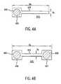
- FIGS. 4A-4Dschematically illustrate aiming beam LEDs in accordance with preferred embodiments.
- FIG. 4Eschematically illustrates a square aiming beam LED in accordance with an exemplary alternative embodiment and illustrating advantages of the preferred embodiments of FIGS. 4A-4D .
- FIG. 5schematically illustrates preferred electrical components of a bar code reader in accordance with a preferred embodiment.
- FIG. 6illustrates a flow chart describing the image capture process according to the present invention.
- FIG. 1schematically illustrates an opto-electronic module 1 for use in a bar code reader 1 in accordance with a preferred embodiment.
- the module 1includes a frame 2 preferably made of plastic or other molded polymeric and/or synthetic material.
- a printed circuit (PC) board 4is coupled with the frame 2 .
- the PC board 4has a semiconductor sensor device 704 and an LED 702 mounted thereon (see also FIGS. 4 A- 4 E).
- the semiconductor sensor devicepreferably includes a single CMOS chip having a linear array of pixels that are each elongated orthogonal to the linear direction of the array, i.e., parallel to the bars of a bar code symbol 22 .
- the LED 702is preferably also elongated such that it is narrower in the focusing direction of a lens 18 , wherein lens 18 is preferably cylindrical/toroidal and is cylindrical on one side and toroidal on the other, and generally, lens 18 has greater optical power in the direction of the bars forming the bar code.
- the PC board 4preferably includes other semiconductor chips 6 for processing signals received from the sensor device.
- these other chips 6may include a chip for storing electronic images and/or a chip for decoding the signals.
- the lens 18which is preferably cylindrical/toroidal, as mentioned, or at least having high power in the direction of the bars of the bar code symbol 22 , is inserted into the frame 2 for focusing light emitted from the LED 702 as a visible aiming beam 20 for the bar code reader 1 . That is, when the aiming beam is aligned with the bar code symbol 22 , as shown in FIG. 1 , the bar code reader 1 is properly aligned for reading the bar code symbol 22 .
- a molded plastic portion 8 of the lens 18is used for aiding in the insertion of the lens 18 into the frame 2 .
- a focusing lens 16images the bar code symbol onto the sensor device on the PC board 4 .
- the focusing lens 16is preferably mounted in a lens barrel which fits into a cylindrical sleeve 17 in the frame 2 .
- One or more notches 14e.g., as shown in FIG. 1 , may be used for positioning the lens barrel within the sleeve 17 .
- the lens barrel including the focusing lens 16is aligned relative to the sensor device, and is then fixed to the frame 2 , e.g., using a glue hole 10 , as shown in FIG. 1 or by other means understood by those skilled in the art such as a bolt or hook fastener assembly.
- a notch 12is also shown in FIG. 1 that may be preferably used for holding the module 1 in place during the assembly process.
- the focusing lens 16is itself preferably substantially a wide angle lens, e.g., 35 °-40° for reading one-dimensional bar code symbols such as the bar code symbol 22 illustrated schematically in FIG. 1 . Therefore, a bar code symbol 22 that is substantially two inches from the lens 16 , and out to substantially six inches from the lens 16 , may be captured.
- the aperture for the lens 16is preferably elliptical, and may alternatively be circular, square, rectangular or otherwise.
- the systempreferably operates to capture the bar code images with no artificial illumination.
- the lens 16is preferably spherical for capturing more light than an alternative cylindrical lens would. Illumination may alternatively be used with a cylindrical lens 16 .
- FIGS. 2A-2Brespectively illustrate schematically in block form cross-sectional top and side views of a bar code reader in accordance with the preferred embodiment shown in FIG. 1 .
- the bar code readeris incorporated into a molded optical package 110 corresponding to the frame 2 of FIG. 1 .
- Structures and techniques for so doingare disclosed in U.S. patent application Ser. No. 09/880,906, filed Jun. 15, 2001 to Mazz et al., entitled “Molded lmager Optical Package and Linear Detector-Based Scan Engines”, which is assigned to the same assignee as the present application and is hereby incorporated by reference herein.
- the molded optical packageincludes an imaging/decoder integrated circuit (IC) 120 and imaging/focusing lens 140 corresponding to lens 16 of FIG.
- ICimaging/decoder integrated circuit
- the imaging/decoder IC 120is fabricated in accordance with known complementary metal oxide semiconductor (CMOS) techniques.
- CMOScomplementary metal oxide semiconductor
- the imaging/decoder IC 120can comprises a CCD imager with associated decoding circuitry.
- the imaging/decoder IC 120receives an image via imaging/focusing lens 140 .
- an aiming beamis generated by focusing light emitted from LEDs 130 on the target image via aiming lens 150 .
- the location of the target image in the proper field of view of the imaging/decoder ICis aided by projecting an aiming pattern on the target image using the aiming LEDs 130 .
- Illumination/aiming LEDsare focused on a target image through illumination/aiming lenses 150 .
- the volume of the imaging systemis scaled by scaling the pixel pitch of the detector array of imaging/decoder IC 120 .
- the pixel pitchrefers to the spacing between image elements, i.e., pixels, on an image sensor.
- the focal lengthis decreased to maintain a comparable field of view.
- the aperture sizeis kept constant, then the same amount of light is collected per pixel and there is not a loss in imager sensitivity.
- the size of the apertureis not limiting the size of the imager, then in a two-dimensional imaging system all three dimensions scale by the scale factor of the pixel. In a one-dimensional imaging system, two dimensions scale by the scale factor of the pixel.
- the imaging engine of the preferred embodimentis designed to provide a similar depth of focus and similar light throughput for each pixel. This results in a balance with the pixel dynamic range and pixel quantum efficiency.
- the bar code reader of FIGS. 2A-2Bhas a CMOS detector array 120 with an approximately 1 -4 mm length of 256 to 512 pixels each having about a 5 -8 micron width. This results in an advantageously small detector length.
- the focal length of the systemis approximately 5 mm.
- the detector footprintcan be further minimized by making two or more rows of pixels offset, e.g., staggered, from one another.
- an array of 500 pixels with 3 mm pitchhas a length of 1.5 mm.
- the pixel pitchis maintained at 3 mm, but the detector array has a resultant length of 0.75 mm. Since the arrays are offset by half of a pixel, the pixel values can be combined to obtain a resolution equivalent to a 1.5 mm sensor.
- the pixel pitchis maintained at a reasonable level for absorbing photons, but the detector footprint, and thus, the total volume of the system can be dramatically decreased.
- the imaging detector array, read-out electronics, analog-to-digital converter and decoding logicare all integrated into a single chip.
- the imaging/decoding chipis mounted on a carrier with at least one LED die or a small laser.
- the carriercan be an FR 4 substrate, an industry recognized organic substrate, and may contain a lead frame or solder bumps for attachment to a larger circuit board.
- the carrieris covered with a molded plastic piece that has the optical surfaces molded into it.
- the molded plastic coveris optical quality and can tolerate temperatures encountered in automated circuit board assembly.
- the devicemay be configured as a complete scanner, including opto-mechanics and electronics, which could be handled like a surface mount integrated circuit and be compatible with re-flow soldering techniques.
- the devicemay be mechanically attached to a circuit board by solder joints only. Accordingly, screws or other mechanical supports would not be required, thus reducing the size and complexity of a device which incorporates this imaging engine.
- FIGS. 3A-3Bare exploded schematic representations of the bar code reader 1 .
- the bar code reader 1includes the frame 2 and PC board 4 of FIG. 1 .
- the frame 2is shown with the cylindrical/toroidal lens 18 including the molded plastic portion 8 inserted therein, the sleeve 17 with lens barrel containing the focusing lens 16 inserted therein, and the notches 12 and 14 and the glue hole 10 , as described above with reference to FIG. 1 .
- the PC board 4is separated from the frame 2 in the exploded representation of FIG. 3A so that the LED 702 and sensor device 704 of the PC board 4 may be schematically illustrated. It is noted that the LED 702 and sensor device 704 are not drawn to scale in FIG.
- the orientation of the bar code reader 1 with respect to the bar code symbol 22is that its elongated direction is perpendicular to the bar code stripes or bars, as shown, and the proper orientation may be rotated, e.g., by 90°, with the orientations of the lenses 16 , 18 and the LED 702 and sensor device 704 correspondingly rotated.
- the LED 702 for emitting visible light focused by lens 18 to cross the bar code symbol 22 as the aiming beam 20is shown next to the chips 6 , which may be image storage and decoding chips 6 .
- the LED 702is preferably elongated with its narrow dimension in the focusing direction of the lens 18 .
- the lens 18preferably has higher power in the direction of the bar code stripes, is preferably cylindrical/toroidal, and may alternatively be purely a cylindrical lens, or may have some power in the orthogonal direction, e.g., such as to expand the aiming beam orthogonal to the bar code stripes and/or to direct the aiming beam somewhat to the right in FIG.
- the LED 702is preferably a single, elongated LED device, as shown, and may alternatively include a single LED of arbitrary shape or multiple LEDs of arbitrary shape and location, with the condition that the LED 702 /lens 18 combination produce a suitable aiming beam.
- the sensor device 704preferably includes a single semiconductor chip 704 .
- This sensor device chip 704preferably includes multiple sensor pixels arranged as a linear array, as shown in FIG. 3 A.
- the deviceincludes no more than 512 pixels, and preferably between 256 and 512 pixels.
- An arbitrary number of pixelsmay be used between a minimum number (e.g., 256) such that the pattern of the bar code symbol 22 is resolveable and a maximum number (e.g., 512) depending on size constraints due to the selected dimensions of the PC board 4 and the focusing properties of the selected lens 16 .
- a single rowis preferred, more than one row of pixels may be included. For example, two rows of pixels staggered by half their width may make up the sensor device 704 such that the resolution may be enhanced.
- the pixels themselvesare preferably elongated in the direction of the bar code stripes, as shown in FIG. 3 A.
- the aspect ratio of the pixelsis preferably greater than 2 to 1 and more particularly is between 4 to 1 and 8 to 1.
- the pixelspreferably have a short dimension not less than 2 microns and not greater than 8 microns, and may specifically be between 7 microns and 8 microns.
- the pixel array 704is not drawn to scale with the frame 2 and PC board 4 in FIG. 3 A. That is, for example, for 512 pixels each being 8 microns wide and, e.g., 64 microns tall, the sensor device 704 would have an effective area of about 4 mm ⁇ 8 microns (which is substantially smaller than the relative dimensions of the sensor device 704 shown in FIG.
- the advantageous elongated shapes of the preferred pixelsprovides an improved combination of high resolution of the bar code symbol 22 and high angular probability of capture of the bar code symbol image at the sensor device 704 compared with, e.g., a sensor device having a single row of square pixels.
- a PCB assembly 4 ais shown having preferred dimensions of 7.1 mm in height by 19.5 mm in width.
- a chassis 2 ais shown removed from its mount to the PCB assembly 4 a .
- the chassis 2 ahas preferred dimensions of approximately 6.6 mm by 11.45 mm.
- a lens barrel 16 ais shown exploded from the slot in the chassis 2 a so that features of the lens system can be shown.
- the lens systempreferably includes a first lens 16 b preferably made of glass, an aperture 16 c and a second lens 16 d preferably made of plastic.
- a light pipe 18 a and aperture 19are also shown removed from their mount to the apparatus in the exploded view of FIG. 3 B.
- FIGS. 4A-4Dillustrate four different embodiments of elongated LEDs corresponding to the LED 702 described above with reference to FIG. 3A in accordance with the preferred embodiment.
- the preferred LEDs of FIGS. 4A-4Das well as the alternative LED 600 of FIG. 4E , each have a total die area which may be the same, i.e., having similar output power and having similar input power and total real estate requirements, although they differ in shape and/or power input configuration.
- the preferred LED dies 615 , 635 , 655 , 675are thinned in the focusing direction of the lens 18 of FIG.
- the dies 615 , 635 , 655 , 675are elongated in the direction perpendicular to the scan lines of the bar code symbol 22 .
- the LED 615has a square portion 620 and a rectangular portion 625 , the rectangular portion is the above-referred elongated portion.
- the square portion 620has a bonding pad 630 .
- the LED 620has dimensions of Dx by Dy, wherein Dy is the width of the elongated portion 625 . Since the voltage which drives the LED is supplied via the bonding pad, the amount of light power emitting from the LED decreases the further the portion of the LED is from the bonding pad. Accordingly, in FIG. 4A , the amount of light power emitted from portions of the elongated portion 625 decreases for portions further to the right of the bonding pad 630 . However, current LED technology provides sufficient luminescent intensity across the entire LED out to the right edge in FIG. 4 A.
- FIG. 4Billustrates a top view of an LED in accordance with another embodiment.
- the LED 635has two square portions 640 and 647 joined by a rectangular portion 642 .
- Square portion 640has bonding pad 645 located thereon and square portion 647 has bonding pad 650 located thereon.
- FIG. 4Cillustrates a top view of an LED in accordance with yet another embodiment of the present invention.
- a bonding pad 670is placed adjacent to the rectangular portion 660 of LED 655 . Accordingly, the bonding pad 670 does not block any light emitted from the elongated portion.
- the placement of the bonding pad in FIG. 4Bmay result in a reduced amount of light in the center of the rectangular portion
- the placement of the bonding pad 670 in FIG. 4Censures a more uniform distribution of light emitted from the center of the rectangular portion 660 of LED die 655 .
- FIG. 4Dillustrates a top view of an LED in accordance with a fourth embodiment.
- a rectangular portion 680 of the LED die 675is surrounded on all sides by a bonding pad 685 .
- the bonding pad 685By surrounding the rectangular portion 680 of the LED die 675 by the bonding pad 685 , a uniform distribution of light emitted from the whole rectangular portion 680 of the LED die 675 is achieved compared to the LED dies illustrated in FIGS. 4A-4C .
- Dy in FIGS. 4A-4Dmay be reduced to less than or about 50 mm.
- Dx, in FIGS. 4A-4Dis advantageously selected, preferably around 1 mm, such that the total die area of the LED is such that sufficient emitting power is produced.
- the lens 18 of FIG. 1is selected such that the aiming beam is focused to a thin, bright line for providing a sufficiently bright aiming beam 20 , notwithstanding whether, if broadened, the beam would have sufficient power to illuminate the entire bar code symbol 22 .
- FIG. 4Eillustrates a top view of a square LED 600 such as may be used for generating a combined illumination/aiming beam, or even for providing only an aiming beam such as that mentioned above with reference to FIG. 1 .
- the LED 600includes a bonding pad 610 through which electrical power is supplied to the LED 600 .
- the LED 600 illustrated at FIG. 4Ehas a square shape and may have dimensions around approximately 300 mm by 300 mm. As illustrated in FIG. 4E , the bonding pad 610 may be typically placed in the middle of the LED 600 .
- This placement of the bonding pad 610blocks approximately 30% of the light power emitting from the LED 600 .
- the square LED of FIG. 4Eproduces less focused light than a laser, the result of which is projected light having an aspect ratio of 1:1 before being focused by lens 18 .
- the elongated LEDs 615 , 635 , 655 and 675 described above with reference to FIGS. 4A-4D , respectively,are preferred over the square LED 600 of FIG. 4 E.
- this aiming beam 20is not otherwise needed to illuminate the bar code symbol 22 so that the reader 1 can capture it with sufficient intensity to resolve the scan lines.
- the aiming beamis preferably only used to align the reader 1 , and thus a bright thin line is preferred over broad illumination, although the aiming beam may advantageously be used for both aiming and illumination.
- the advantageous LEDs 615 , 635 , 655 and 675 described above with reference to FIGS. 4A-4D , respectively,provide the desired bright, thin aiming beam 20 , i.e., in conjunction with the lens 18 preferably having high power in the direction of the scan lines of the symbol 22 (e.g., the preferred lens 18 is a cylindrical/toroidal lens 18 , as described above with reference to FIG. 1 ).
- FIG. 5illustrates the electronics of a bar code reader in accordance with a preferred embodiment.
- These electronicsinclude a two-dimensional sensor device 410 which is controlled via clock driver and charge pump 420 .
- Clock driver and charge pump 420are controlled in accordance with signals received from timing generator 430 .
- An image captured by sensor device 410is provided to correlated double sampling block 440 . Since pixels do not always return to the same value when they are reset, correlated double sampling is used to remove the offset introduced by pixels which have not returned to their normal reset values. Accordingly, correlated double sampling involves capturing two values of the pixels, the first value is the value of the pixels with the desired image, e.g., a one-dimensional bar code, and the second value is the value of the pixels after being reset.
- the two values of each pixelare compared to remove the offset introduced by pixels which have not returned to their normal reset value.
- the imageis passed through a weak AC coupling to block DC content of the correlated double sampled image.
- an automatic gain control 442amplifies the signal which is then provided to an analog-to-digital converter 444 .
- the analog-to-digital converteris a nine bit analog-to-digital converter.
- Digital datais provided by the analog-to-digital converter to the glue logic field programmable gate array (FPGA) block 450 .
- the glue logic/FPGA 450packs the digital data so that it can be read by microprocessor 460 and connects with the microprocessor 460 to provide all of the device controls.
- the microprocessor 460includes DRAM embedded on the same IC as the microprocessor which increases the speed of the system while allowing a reduced size and cost for the resultant imager.
- the microprocessor 460operates under control of a program stored in flash memory 470 via an external data and address bus.
- the target imagee.g., such as the bar code symbol 22 of FIG. 1
- the target imageis preferably sufficiently illuminated by ambient light due to the opto-electronic configuration of the preferred bar code reader 1 of FIG. 1 , so that the bar code symbol 22 is resolvable without additional illumination.
- illuminationmay be provided by one or more 650 nm red LEDs of an optional illumination module 475 . The LEDs would be arranged so that the target image is uniformly illuminated.
- the preferred aiming module 480is preferably used to provide a unique aiming pattern.
- Aiming module 480can include an elongated LED (see FIGS. 3 A and 4 A- 4 D) and lens 18 of FIGS. 1 and 3 , or alternatively may include a laser diode and a diffractive optical element (DOE) to provide the unique aiming pattern.
- Interaction between a host device which may incorporate the preferred bar code reader 1 of FIG. 1may be provided using host interface 490 of FIG. 5 . Since the preferred bar code reader 1 described herein is miniature, i.e., of a small form factor, a host device may be a portable radio telephone (cellular phone), a personal digital assistant (PDA), or the like. Using the elements described in connection with FIG. 5 , a miniature bar code reader device can be achieved which can be manufactured in a SE900 or smaller form factor which may be used in the imager industry for the manufacture of imaging devices.
- the module 1includes a one-dimensional, solid-state, image sensor 704 or a two-dimensional, solid-state, image sensor 410 for capturing an image of a target.
- the module 1is positioned within a handheld device having a trigger which, when manually actuated, initiates image capture and, hence, reading of a bar code symbol 22 as the target.
- the LED 702 and the lens 18together form the aiming line 20 on the symbol to facilitate proper positioning of the sensor relative to the symbol.
- the light from the LED 702helps to illuminate the symbol.
- the LEDis constantly energized so that the light emitted from the LED is constant.
- a moving laser beam scannertypically sweeps a laser spot a plurality of times a second across a symbol, each sweep defining a scan line. Scan lines are typically swept at a rate of 20-40 scans per second. As a consequence, a user of the known moving beam scanner expects to see a flickering scan line on and across the symbol being read. With the solid-state system, no such flickering scan lines are present and, as a result, the user of a solid-state system does not experience any visual feedback. This is disadvantageous, because the user may be uncertain that the solid-state system is working.
- this inventionproposes, as shown in the flow chart of FIG. 6 , to use the LED 702 and the lens 18 to form a visible line on the symbol, and to turn the visible line on and off, thereby causing the visible line to flicker and simulate a moving laser beam.
- various parameters of the modulefor example, the exposure time of the sensor are initialized (block 504 ).
- the LED 702is energized, and the visible line 20 is turned on (block 506 ).
- the LED lightby itself covers a wide area on the order of 1 cm wide.
- the lens 18narrows the width and, if necessary, an aperture stop can be used to narrow the width of the light emitted from the LED.
- the triggeris pulled (block 508 ), and the visible line is turned off, thereby causing the visible line to flicker (block 510 ).
- the sensorcaptures the image of the target (block 512 ), after which, the visible line is turned on again (block 514 ).
- the pixel qualityis tested (block 516 ) and, if found to be good, the electrical signal produced by the sensor is digitized (block 518 ) and attempted to be decoded (block 520 ). If not decoded, then the user is prompted to pull the trigger again.
- the decoded signalis processed, the result is stored (block 522 ), and auditory beep (block 524 ) is annunciated to signify a successful decode, and the system readies itself for the next symbol to be read.
- the exposure time of the sensoris recomputed and adjusted, either longer or shorter (block 526 ).
- the initialized exposure timeis typically 10 ms and is adjustable depending on ambient light from about 60 ⁇ s to about 30 ms. After adjustment, the visible line is turned off again (block 528 ) prior to capturing the image at block 512 .
- the flickering visible linesimulates the experience of a user who previously was accustomed to operating moving laser beam scanners and increases the comfort level of the user who is new to using sensor-based systems.
Landscapes
- Physics & Mathematics (AREA)
- Engineering & Computer Science (AREA)
- Electromagnetism (AREA)
- Artificial Intelligence (AREA)
- Toxicology (AREA)
- General Health & Medical Sciences (AREA)
- Health & Medical Sciences (AREA)
- Computer Vision & Pattern Recognition (AREA)
- General Physics & Mathematics (AREA)
- Theoretical Computer Science (AREA)
- Facsimile Scanning Arrangements (AREA)
- Image Input (AREA)
- Mechanical Optical Scanning Systems (AREA)
- Studio Devices (AREA)
- Facsimile Heads (AREA)
Abstract
Description
Claims (18)
Priority Applications (3)
| Application Number | Priority Date | Filing Date | Title |
|---|---|---|---|
| US10/271,039US6866198B2 (en) | 2002-10-15 | 2002-10-15 | Imaging bar code reader with moving beam simulation |
| CNB2003101138909ACN100371941C (en) | 2002-10-15 | 2003-10-14 | Imagingbar code reader with movable light beam simulation |
| JP2003354948AJP2004151711A (en) | 2002-10-15 | 2003-10-15 | Imaging bar code reader with moving beam simulation |
Applications Claiming Priority (1)
| Application Number | Priority Date | Filing Date | Title |
|---|---|---|---|
| US10/271,039US6866198B2 (en) | 2002-10-15 | 2002-10-15 | Imaging bar code reader with moving beam simulation |
Publications (2)
| Publication Number | Publication Date |
|---|---|
| US20040069855A1 US20040069855A1 (en) | 2004-04-15 |
| US6866198B2true US6866198B2 (en) | 2005-03-15 |
Family
ID=32069068
Family Applications (1)
| Application Number | Title | Priority Date | Filing Date |
|---|---|---|---|
| US10/271,039Expired - LifetimeUS6866198B2 (en) | 2002-10-15 | 2002-10-15 | Imaging bar code reader with moving beam simulation |
Country Status (3)
| Country | Link |
|---|---|
| US (1) | US6866198B2 (en) |
| JP (1) | JP2004151711A (en) |
| CN (1) | CN100371941C (en) |
Cited By (19)
| Publication number | Priority date | Publication date | Assignee | Title |
|---|---|---|---|---|
| US20040173681A1 (en)* | 2003-03-03 | 2004-09-09 | Denso Wave Incorporated Denso Elecs Co., Ltd. | Optical information reading apparatus |
| US20050006475A1 (en)* | 2003-01-09 | 2005-01-13 | Pettinelli John A. | Analog-to-digital converter with automatic range and sensitivity adjustment |
| US20090001169A1 (en)* | 2007-06-28 | 2009-01-01 | Symbol Technologies, Inc. | Bar code reader with improved lens for imaging with balanced astigmatism |
| US20090090782A1 (en)* | 2007-10-09 | 2009-04-09 | Hewlett-Packard Development Company Lp | Alignment and non-alignment assist images |
| WO2010014084A1 (en)* | 2008-07-30 | 2010-02-04 | Optoelectronics Co., Ltd. | One dimensional barcode reader using two dimensional image sensor |
| US20100176319A1 (en)* | 2009-01-12 | 2010-07-15 | Cognex Corporation | Modular focus system for image based code readers (as amended) |
| US20100181378A1 (en)* | 2007-03-09 | 2010-07-22 | Optoelectronics Co., Ltd. | Beverage maker with compact optical code reader |
| US20100213258A1 (en)* | 2009-02-24 | 2010-08-26 | Rong Liu | Arrangement for and method of generating uniform distributed line pattern for imaging reader |
| US7957554B1 (en) | 2002-12-31 | 2011-06-07 | Cognex Technology And Investment Corporation | Method and apparatus for human interface to a machine vision system |
| US8181878B2 (en) | 2006-01-25 | 2012-05-22 | Cognex Technology And Investment Corporation | Method and apparatus for providing a focus indication for optical imaging of visual codes |
| US8302864B2 (en) | 2007-12-28 | 2012-11-06 | Cognex Corporation | Method and apparatus using aiming pattern for machine vision training |
| WO2013105921A1 (en)* | 2011-12-12 | 2013-07-18 | Optoelectronics Co., Ltd. | Miniature imaging and decoding module |
| US8646689B2 (en) | 2007-12-28 | 2014-02-11 | Cognex Corporation | Deformable light pattern for machine vision system |
| US9746636B2 (en) | 2012-10-19 | 2017-08-29 | Cognex Corporation | Carrier frame and circuit board for an electronic device |
| US10067312B2 (en) | 2011-11-22 | 2018-09-04 | Cognex Corporation | Vision system camera with mount for multiple lens types |
| US10498934B2 (en) | 2011-11-22 | 2019-12-03 | Cognex Corporation | Camera system with exchangeable illumination assembly |
| US10528772B1 (en) | 2012-02-24 | 2020-01-07 | Socket Mobile, Inc. | Assisted aimer for optimized symbol scanning by a portable computing device having an integral camera |
| US11366284B2 (en) | 2011-11-22 | 2022-06-21 | Cognex Corporation | Vision system camera with mount for multiple lens types and lens module for the same |
| US11442256B2 (en) | 2018-11-14 | 2022-09-13 | Largan Precision Co., Ltd. | Imaging optical lens assembly, imaging apparatus and electronic device |
Families Citing this family (26)
| Publication number | Priority date | Publication date | Assignee | Title |
|---|---|---|---|---|
| US6666377B1 (en)* | 2000-07-18 | 2003-12-23 | Scott C. Harris | Bar code data entry device |
| US7014114B2 (en)* | 2003-10-02 | 2006-03-21 | Symbol Technologies, Inc. | Image capture device for and method of electro-optically reading indicia at low ambient light levels |
| US7874487B2 (en) | 2005-10-24 | 2011-01-25 | Cognex Technology And Investment Corporation | Integrated illumination assembly for symbology reader |
| US9070031B2 (en) | 2003-10-24 | 2015-06-30 | Cognex Technology And Investment Llc | Integrated illumination assembly for symbology reader |
| US7823783B2 (en) | 2003-10-24 | 2010-11-02 | Cognex Technology And Investment Corporation | Light pipe illumination system and method |
| US7823789B2 (en) | 2004-12-21 | 2010-11-02 | Cognex Technology And Investment Corporation | Low profile illumination for direct part mark readers |
| US7604174B2 (en) | 2003-10-24 | 2009-10-20 | Cognex Technology And Investment Corporation | Method and apparatus for providing omnidirectional lighting in a scanning device |
| US9536124B1 (en) | 2003-10-24 | 2017-01-03 | Cognex Corporation | Integrated illumination assembly for symbology reader |
| US7201321B2 (en)* | 2004-08-27 | 2007-04-10 | Symbol Technologies, Inc. | Electro-optically reading direct part markings on workpieces by image capture |
| US9292724B1 (en) | 2004-12-16 | 2016-03-22 | Cognex Corporation | Hand held symbology reader illumination diffuser with aimer optics |
| US7617984B2 (en) | 2004-12-16 | 2009-11-17 | Cognex Technology And Investment Corporation | Hand held symbology reader illumination diffuser |
| US7494065B2 (en)* | 2005-08-11 | 2009-02-24 | Symbol Technologies, Inc. | Optical code reader system and method for control of illumination for aiming and exposure |
| KR100752610B1 (en) | 2006-01-06 | 2007-08-29 | (주)블루버드 소프트 | Barcode scanner |
| JP4205117B2 (en)* | 2006-05-22 | 2009-01-07 | シャープ株式会社 | Optical reflective information reading sensor and electronic device |
| US7387252B2 (en)* | 2006-08-15 | 2008-06-17 | Hand Held Products, Inc. | Optical reader with improved lens focusing system |
| US8201740B2 (en)* | 2007-09-28 | 2012-06-19 | Symbol Technologies, Inc. | Imaging reader for and method of improving visibility of aiming pattern |
| US8061616B2 (en)* | 2009-12-18 | 2011-11-22 | Symbol Technologies, Inc. | Aiming sight for a barcode reader |
| US9418270B2 (en)* | 2011-01-31 | 2016-08-16 | Hand Held Products, Inc. | Terminal with flicker-corrected aimer and alternating illumination |
| US8523074B2 (en)* | 2011-08-26 | 2013-09-03 | Honeywell International Inc. | Bar code imagers |
| CN103780847A (en) | 2012-10-24 | 2014-05-07 | 霍尼韦尔国际公司 | Chip on board-based highly-integrated imager |
| US9665757B2 (en) | 2014-03-07 | 2017-05-30 | Hand Held Products, Inc. | Indicia reader for size-limited applications |
| USD737822S1 (en)* | 2014-03-10 | 2015-09-01 | Datalogic Ip Tech S.R.L. | Optical module |
| USD805078S1 (en) | 2015-05-07 | 2017-12-12 | Datalogic Ip Tech S.R.L. | Barcode reading module |
| CN105005754B (en)* | 2015-08-14 | 2018-05-29 | 福建联迪商用设备有限公司 | A kind of dimensional code scanner of shared light compensating lamp and alignment lamp |
| CN108957737B (en)* | 2018-06-12 | 2021-06-04 | 上海视界纵横智能科技有限公司 | Visual feedback laser scanning system |
| JP2023054552A (en)* | 2021-10-04 | 2023-04-14 | ローランドディー.ジー.株式会社 | Pointer and inkjet printer having the same |
Citations (26)
| Publication number | Priority date | Publication date | Assignee | Title |
|---|---|---|---|---|
| US5283699A (en)* | 1991-12-28 | 1994-02-01 | Neorex Co., Ltd. | Micro-bar code reader system |
| US5354977A (en)* | 1992-02-27 | 1994-10-11 | Alex Roustaei | Optical scanning head |
| US5481099A (en)* | 1989-10-30 | 1996-01-02 | Symbol Technologies, Inc. | Scanning arrangement for the implementation of omni-directional scanning patterns over indicia |
| US5621203A (en)* | 1992-09-25 | 1997-04-15 | Symbol Technologies | Method and apparatus for reading two-dimensional bar code symbols with an elongated laser line |
| US5747785A (en)* | 1987-12-21 | 1998-05-05 | Miller; Phillip | Integrated hand-held bar code processing device capable of automatic scan and data display |
| US5798516A (en)* | 1996-05-28 | 1998-08-25 | Accu-Sort Systems, Inc. | Focusing mechanism for hand-held CCD scanners |
| US5874720A (en)* | 1989-10-30 | 1999-02-23 | Symbol Technologies, Inc. | Electro-magnetically activated scanner with suspended scanner component |
| US5949052A (en)* | 1997-10-17 | 1999-09-07 | Welch Allyn, Inc. | Object sensor system for stationary position optical reader |
| US5959286A (en)* | 1994-05-18 | 1999-09-28 | Symbol Technologies, Inc. | Method and apparatus for raster scanning of images |
| US5969323A (en)* | 1995-10-05 | 1999-10-19 | Symbol Technologies, Inc. | Noise-reduced electro-optical readers with optical bandpass filter |
| US6073848A (en)* | 1998-05-18 | 2000-06-13 | Symbol Technologies, Inc. | Digital automatic gain control for multi-stage amplification circuits |
| US6124950A (en)* | 1997-04-15 | 2000-09-26 | Minolta Co., Ltd. | Apparatus and method for detecting book document along the longitudinal edge |
| US6145743A (en)* | 1995-06-19 | 2000-11-14 | Symbol Technologies, Inc. | Light collection systems in electro-optical readers |
| US6149061A (en)* | 1997-07-30 | 2000-11-21 | Intermec Ip Corp. | Optoelectronic device for multidirectional capture of images of plane objects, in particular bar codes |
| US6163414A (en)* | 1997-10-20 | 2000-12-19 | Fuji Xerox Co., Ltd. | Image reading apparatus |
| US20020044205A1 (en)* | 2000-09-08 | 2002-04-18 | Hidetada Nagaoka | Image pickup apparatus with reduced flicker and automatic level adjusting method of the same |
| US20020043562A1 (en)* | 1998-04-07 | 2002-04-18 | Victor Zazzu | Multi sensor information reader |
| US20020067341A1 (en)* | 2000-12-06 | 2002-06-06 | Kiwamu Kobayashi | Photodetector, photosensing position detector, coordinate input device, coordinate input/output apparatus, and photodetection method |
| US20020117547A1 (en)* | 1994-06-30 | 2002-08-29 | Mark Krichever | Apparatus and method for reading indicia using charge coupled device and scanning laser beam technology |
| US20020117574A1 (en)* | 2001-02-27 | 2002-08-29 | Ronald Hawley | Wire spool stay |
| US6491225B1 (en)* | 1989-10-30 | 2002-12-10 | Symbol Technologies, Inc. | Electro-optical reader with electronic stylus |
| US20030024990A1 (en)* | 1990-09-10 | 2003-02-06 | Wilz David M. | Portable hand-supportable data terminal with automatically-activated laser scanning bar code symbol reader |
| US6601768B2 (en)* | 2001-03-08 | 2003-08-05 | Welch Allyn Data Collection, Inc. | Imaging module for optical reader comprising refractive diffuser |
| US20030218069A1 (en)* | 1999-11-02 | 2003-11-27 | Welch Allyn Data Collection, Inc. | Indicia sensor system for optical reader |
| US20040056101A1 (en)* | 2001-04-10 | 2004-03-25 | Edward Barkan | Retail sales customer marketing system with electronic coupon processing |
| US6749120B2 (en)* | 2000-12-11 | 2004-06-15 | Cpo Technologies Corp. | Method and apparatus for scanning electronic barcodes |
Family Cites Families (14)
| Publication number | Priority date | Publication date | Assignee | Title |
|---|---|---|---|---|
| JPH07107688B2 (en)* | 1986-03-18 | 1995-11-15 | 日本電装株式会社 | Optical information reader |
| US5258605A (en)* | 1990-03-13 | 1993-11-02 | Symbol Technologies, Inc. | Scan generators for bar code reader using linear array of lasers |
| JPH04220786A (en)* | 1990-03-13 | 1992-08-11 | Symbol Technol Inc | Bar code scanner |
| JPH04181288A (en)* | 1990-11-16 | 1992-06-29 | Seiko Epson Corp | Picture display device |
| CN1042982C (en)* | 1991-12-14 | 1999-04-14 | 欧林巴斯光学工业股份有限公司 | Non-laser scanner and scan method |
| JPH0793459A (en)* | 1993-09-28 | 1995-04-07 | Tec Corp | Two-dimensional code scanner |
| US5672858A (en)* | 1994-06-30 | 1997-09-30 | Symbol Technologies Inc. | Apparatus and method for reading indicia using charge coupled device and scanning laser beam technology |
| JPH08153157A (en)* | 1994-11-28 | 1996-06-11 | Nippondenso Co Ltd | Optical information reader |
| JP3698788B2 (en)* | 1995-02-01 | 2005-09-21 | シンボル テクノロジーズ インコーポレイテッド | Optical system and optical pointer module |
| JPH09237315A (en)* | 1996-03-01 | 1997-09-09 | Asahi Optical Co Ltd | Symbol reader |
| JPH10334173A (en)* | 1997-05-30 | 1998-12-18 | Tec Corp | Two-dimensional code reader and two-dimensional code reader system |
| AU7992000A (en)* | 1999-10-04 | 2001-05-10 | Welch Allyn Data Collection, Inc. | Imaging module for optical reader |
| CN1325084A (en)* | 2000-05-22 | 2001-12-05 | 昆盈企业股份有限公司 | barcode scanning device |
| JP2002230476A (en)* | 2001-02-01 | 2002-08-16 | Canon Inc | 2D barcode reader |
- 2002
- 2002-10-15USUS10/271,039patent/US6866198B2/ennot_activeExpired - Lifetime
- 2003
- 2003-10-14CNCNB2003101138909Apatent/CN100371941C/ennot_activeExpired - Fee Related
- 2003-10-15JPJP2003354948Apatent/JP2004151711A/enactivePending
Patent Citations (26)
| Publication number | Priority date | Publication date | Assignee | Title |
|---|---|---|---|---|
| US5747785A (en)* | 1987-12-21 | 1998-05-05 | Miller; Phillip | Integrated hand-held bar code processing device capable of automatic scan and data display |
| US5481099A (en)* | 1989-10-30 | 1996-01-02 | Symbol Technologies, Inc. | Scanning arrangement for the implementation of omni-directional scanning patterns over indicia |
| US5874720A (en)* | 1989-10-30 | 1999-02-23 | Symbol Technologies, Inc. | Electro-magnetically activated scanner with suspended scanner component |
| US6491225B1 (en)* | 1989-10-30 | 2002-12-10 | Symbol Technologies, Inc. | Electro-optical reader with electronic stylus |
| US20030024990A1 (en)* | 1990-09-10 | 2003-02-06 | Wilz David M. | Portable hand-supportable data terminal with automatically-activated laser scanning bar code symbol reader |
| US5283699A (en)* | 1991-12-28 | 1994-02-01 | Neorex Co., Ltd. | Micro-bar code reader system |
| US5354977A (en)* | 1992-02-27 | 1994-10-11 | Alex Roustaei | Optical scanning head |
| US5621203A (en)* | 1992-09-25 | 1997-04-15 | Symbol Technologies | Method and apparatus for reading two-dimensional bar code symbols with an elongated laser line |
| US5959286A (en)* | 1994-05-18 | 1999-09-28 | Symbol Technologies, Inc. | Method and apparatus for raster scanning of images |
| US20020117547A1 (en)* | 1994-06-30 | 2002-08-29 | Mark Krichever | Apparatus and method for reading indicia using charge coupled device and scanning laser beam technology |
| US6145743A (en)* | 1995-06-19 | 2000-11-14 | Symbol Technologies, Inc. | Light collection systems in electro-optical readers |
| US5969323A (en)* | 1995-10-05 | 1999-10-19 | Symbol Technologies, Inc. | Noise-reduced electro-optical readers with optical bandpass filter |
| US5798516A (en)* | 1996-05-28 | 1998-08-25 | Accu-Sort Systems, Inc. | Focusing mechanism for hand-held CCD scanners |
| US6124950A (en)* | 1997-04-15 | 2000-09-26 | Minolta Co., Ltd. | Apparatus and method for detecting book document along the longitudinal edge |
| US6149061A (en)* | 1997-07-30 | 2000-11-21 | Intermec Ip Corp. | Optoelectronic device for multidirectional capture of images of plane objects, in particular bar codes |
| US5949052A (en)* | 1997-10-17 | 1999-09-07 | Welch Allyn, Inc. | Object sensor system for stationary position optical reader |
| US6163414A (en)* | 1997-10-20 | 2000-12-19 | Fuji Xerox Co., Ltd. | Image reading apparatus |
| US20020043562A1 (en)* | 1998-04-07 | 2002-04-18 | Victor Zazzu | Multi sensor information reader |
| US6073848A (en)* | 1998-05-18 | 2000-06-13 | Symbol Technologies, Inc. | Digital automatic gain control for multi-stage amplification circuits |
| US20030218069A1 (en)* | 1999-11-02 | 2003-11-27 | Welch Allyn Data Collection, Inc. | Indicia sensor system for optical reader |
| US20020044205A1 (en)* | 2000-09-08 | 2002-04-18 | Hidetada Nagaoka | Image pickup apparatus with reduced flicker and automatic level adjusting method of the same |
| US20020067341A1 (en)* | 2000-12-06 | 2002-06-06 | Kiwamu Kobayashi | Photodetector, photosensing position detector, coordinate input device, coordinate input/output apparatus, and photodetection method |
| US6749120B2 (en)* | 2000-12-11 | 2004-06-15 | Cpo Technologies Corp. | Method and apparatus for scanning electronic barcodes |
| US20020117574A1 (en)* | 2001-02-27 | 2002-08-29 | Ronald Hawley | Wire spool stay |
| US6601768B2 (en)* | 2001-03-08 | 2003-08-05 | Welch Allyn Data Collection, Inc. | Imaging module for optical reader comprising refractive diffuser |
| US20040056101A1 (en)* | 2001-04-10 | 2004-03-25 | Edward Barkan | Retail sales customer marketing system with electronic coupon processing |
Cited By (37)
| Publication number | Priority date | Publication date | Assignee | Title |
|---|---|---|---|---|
| US7957554B1 (en) | 2002-12-31 | 2011-06-07 | Cognex Technology And Investment Corporation | Method and apparatus for human interface to a machine vision system |
| US8625880B2 (en) | 2002-12-31 | 2014-01-07 | Cognex Technology And Investment Corporation | Method and apparatus for human interface to a machine vision system |
| US20050006475A1 (en)* | 2003-01-09 | 2005-01-13 | Pettinelli John A. | Analog-to-digital converter with automatic range and sensitivity adjustment |
| US7175092B2 (en)* | 2003-01-09 | 2007-02-13 | Hand Held Products, Inc. | Analog-to-digital converter with automatic range and sensitivity adjustment |
| US20070228170A1 (en)* | 2003-01-09 | 2007-10-04 | Pettinelli John A Jr | Analog-to-digital converter with automatic range and sensitivity adjustment |
| US7413126B2 (en) | 2003-01-09 | 2008-08-19 | Hand Held Products, Inc. | Analog-to-digital converter with automatic range and sensitivity adjustment |
| US7083097B2 (en)* | 2003-03-03 | 2006-08-01 | Denso Wave Incorporated | Optical information reading apparatus |
| US20040173681A1 (en)* | 2003-03-03 | 2004-09-09 | Denso Wave Incorporated Denso Elecs Co., Ltd. | Optical information reading apparatus |
| US8181878B2 (en) | 2006-01-25 | 2012-05-22 | Cognex Technology And Investment Corporation | Method and apparatus for providing a focus indication for optical imaging of visual codes |
| US20100181378A1 (en)* | 2007-03-09 | 2010-07-22 | Optoelectronics Co., Ltd. | Beverage maker with compact optical code reader |
| US8201743B2 (en)* | 2007-06-28 | 2012-06-19 | Symbol Technologies, Inc. | Bar code reader with improved lens for imaging with balanced astigmatism |
| US20090001169A1 (en)* | 2007-06-28 | 2009-01-01 | Symbol Technologies, Inc. | Bar code reader with improved lens for imaging with balanced astigmatism |
| US8016198B2 (en) | 2007-10-09 | 2011-09-13 | Hewlett-Packard Development Company, L.P. | Alignment and non-alignment assist images |
| US20090090782A1 (en)* | 2007-10-09 | 2009-04-09 | Hewlett-Packard Development Company Lp | Alignment and non-alignment assist images |
| US8302864B2 (en) | 2007-12-28 | 2012-11-06 | Cognex Corporation | Method and apparatus using aiming pattern for machine vision training |
| US8646689B2 (en) | 2007-12-28 | 2014-02-11 | Cognex Corporation | Deformable light pattern for machine vision system |
| WO2010014084A1 (en)* | 2008-07-30 | 2010-02-04 | Optoelectronics Co., Ltd. | One dimensional barcode reader using two dimensional image sensor |
| US20100176319A1 (en)* | 2009-01-12 | 2010-07-15 | Cognex Corporation | Modular focus system for image based code readers (as amended) |
| US8134116B2 (en) | 2009-01-12 | 2012-03-13 | Cognex Corporation | Modular focus system for image based code readers |
| US8803060B2 (en) | 2009-01-12 | 2014-08-12 | Cognex Corporation | Modular focus system alignment for image based readers |
| US20100213258A1 (en)* | 2009-02-24 | 2010-08-26 | Rong Liu | Arrangement for and method of generating uniform distributed line pattern for imaging reader |
| US10678019B2 (en) | 2011-11-22 | 2020-06-09 | Cognex Corporation | Vision system camera with mount for multiple lens types |
| US11115566B2 (en) | 2011-11-22 | 2021-09-07 | Cognex Corporation | Camera system with exchangeable illumination assembly |
| US10067312B2 (en) | 2011-11-22 | 2018-09-04 | Cognex Corporation | Vision system camera with mount for multiple lens types |
| US10498934B2 (en) | 2011-11-22 | 2019-12-03 | Cognex Corporation | Camera system with exchangeable illumination assembly |
| US10498933B2 (en) | 2011-11-22 | 2019-12-03 | Cognex Corporation | Camera system with exchangeable illumination assembly |
| US11936964B2 (en) | 2011-11-22 | 2024-03-19 | Cognex Corporation | Camera system with exchangeable illumination assembly |
| US11921350B2 (en) | 2011-11-22 | 2024-03-05 | Cognex Corporation | Vision system camera with mount for multiple lens types and lens module for the same |
| US11366284B2 (en) | 2011-11-22 | 2022-06-21 | Cognex Corporation | Vision system camera with mount for multiple lens types and lens module for the same |
| WO2013105921A1 (en)* | 2011-12-12 | 2013-07-18 | Optoelectronics Co., Ltd. | Miniature imaging and decoding module |
| US10909340B2 (en) | 2012-02-24 | 2021-02-02 | Socket Mobile, Inc. | Aimer beam formation facilitating rapid barcode processing by a user with a standard smart phone |
| US10719675B2 (en) | 2012-02-24 | 2020-07-21 | Socket Mobile, Inc. | Assisted aimer for optimized symbol scanning by a portable computing device having an integral camera |
| US10528772B1 (en) | 2012-02-24 | 2020-01-07 | Socket Mobile, Inc. | Assisted aimer for optimized symbol scanning by a portable computing device having an integral camera |
| US12265878B2 (en) | 2012-02-24 | 2025-04-01 | Socket Mobile, Inc. | Assisted aimer for optimized symbol scanning by a portable computing device having an integral camera |
| US10754122B2 (en) | 2012-10-19 | 2020-08-25 | Cognex Corporation | Carrier frame and circuit board for an electronic device |
| US9746636B2 (en) | 2012-10-19 | 2017-08-29 | Cognex Corporation | Carrier frame and circuit board for an electronic device |
| US11442256B2 (en) | 2018-11-14 | 2022-09-13 | Largan Precision Co., Ltd. | Imaging optical lens assembly, imaging apparatus and electronic device |
Also Published As
| Publication number | Publication date |
|---|---|
| US20040069855A1 (en) | 2004-04-15 |
| CN100371941C (en) | 2008-02-27 |
| CN1497490A (en) | 2004-05-19 |
| JP2004151711A (en) | 2004-05-27 |
Similar Documents
| Publication | Publication Date | Title |
|---|---|---|
| US6866198B2 (en) | Imaging bar code reader with moving beam simulation | |
| US6811085B2 (en) | Miniature imager | |
| US6685092B2 (en) | Molded imager optical package and miniaturized linear sensor-based code reading engines | |
| US7705288B2 (en) | Optical reading device with light blocking gasket | |
| EP0980537B1 (en) | Optical scanner and image reader for reading images and decoding optical information including one and two dimensional symbologies at variable depth of field | |
| US6766954B2 (en) | Omnidirectional linear sensor-based code reading engines | |
| US8910872B2 (en) | Imaging reader and method with dual function illumination light assembly | |
| US20070164111A1 (en) | Optical reader | |
| US20100096459A1 (en) | Electro-optical reader with extended working range | |
| JP6053224B2 (en) | Image reading device | |
| JPH11514461A (en) | Data form reader and method | |
| US8657199B2 (en) | Compact imaging engine for imaging reader | |
| US20100078483A1 (en) | Arrangement for and method of generating uniform distributed line pattern for imaging reader | |
| US6837431B2 (en) | Semiconductor device adapted for imaging bar code symbols | |
| TWI227447B (en) | Semiconductor device adapted for imaging bar code symbols | |
| US8006906B2 (en) | Arrangement for and method of generating uniform distributed line pattern for imaging reader | |
| GB2418512A (en) | Pixel array for an imaging system | |
| EP1916557B1 (en) | Optical scanner and image reader for reading images and decoding optical information including one and two dimensional symbologies at variable depth of field | |
| US7679724B2 (en) | Determining target distance in imaging reader |
Legal Events
| Date | Code | Title | Description |
|---|---|---|---|
| AS | Assignment | Owner name:SYMBOL TECHNOLOGIES, INC., NEW YORK Free format text:ASSIGNMENT OF ASSIGNORS INTEREST;ASSIGNORS:PATEL, MEHUL;PREUSS, WALTER;DVORKIS, PAUL;REEL/FRAME:013393/0635 Effective date:20021009 | |
| STCF | Information on status: patent grant | Free format text:PATENTED CASE | |
| FPAY | Fee payment | Year of fee payment:4 | |
| FPAY | Fee payment | Year of fee payment:8 | |
| AS | Assignment | Owner name:MORGAN STANLEY SENIOR FUNDING, INC. AS THE COLLATERAL AGENT, MARYLAND Free format text:SECURITY AGREEMENT;ASSIGNORS:ZIH CORP.;LASER BAND, LLC;ZEBRA ENTERPRISE SOLUTIONS CORP.;AND OTHERS;REEL/FRAME:034114/0270 Effective date:20141027 Owner name:MORGAN STANLEY SENIOR FUNDING, INC. AS THE COLLATE Free format text:SECURITY AGREEMENT;ASSIGNORS:ZIH CORP.;LASER BAND, LLC;ZEBRA ENTERPRISE SOLUTIONS CORP.;AND OTHERS;REEL/FRAME:034114/0270 Effective date:20141027 | |
| AS | Assignment | Owner name:SYMBOL TECHNOLOGIES, LLC, NEW YORK Free format text:CHANGE OF NAME;ASSIGNOR:SYMBOL TECHNOLOGIES, INC.;REEL/FRAME:036083/0640 Effective date:20150410 | |
| AS | Assignment | Owner name:SYMBOL TECHNOLOGIES, INC., NEW YORK Free format text:RELEASE BY SECURED PARTY;ASSIGNOR:MORGAN STANLEY SENIOR FUNDING, INC.;REEL/FRAME:036371/0738 Effective date:20150721 | |
| FPAY | Fee payment | Year of fee payment:12 |