Movatterモバイル変換


[0]ホーム

URL:


US6865418B2 - Docking station for defibrillator - Google Patents

Docking station for defibrillator
Download PDF

Info

Publication number
US6865418B2
US6865418B2US10/091,631US9163102AUS6865418B2US 6865418 B2US6865418 B2US 6865418B2US 9163102 AUS9163102 AUS 9163102AUS 6865418 B2US6865418 B2US 6865418B2
Authority
US
United States
Prior art keywords
platform
base
defibrillator
coupled
coupling mechanism
Prior art date
Legal status (The legal status is an assumption and is not a legal conclusion. Google has not performed a legal analysis and makes no representation as to the accuracy of the status listed.)
Expired - Lifetime, expires
Application number
US10/091,631
Other versions
US20030167074A1 (en
Inventor
Rodney Merry
Current Assignee (The listed assignees may be inaccurate. Google has not performed a legal analysis and makes no representation or warranty as to the accuracy of the list.)
Physio Control Inc
Original Assignee
Medtronic Physio Control Corp
Priority date (The priority date is an assumption and is not a legal conclusion. Google has not performed a legal analysis and makes no representation as to the accuracy of the date listed.)
Filing date
Publication date
Application filed by Medtronic Physio Control CorpfiledCriticalMedtronic Physio Control Corp
Priority to US10/091,631priorityCriticalpatent/US6865418B2/en
Assigned to MEDTRONIC PHYSIO-CONTROL CORP.reassignmentMEDTRONIC PHYSIO-CONTROL CORP.ASSIGNMENT OF ASSIGNORS INTEREST (SEE DOCUMENT FOR DETAILS).Assignors: MERRY, RODNEY
Publication of US20030167074A1publicationCriticalpatent/US20030167074A1/en
Application grantedgrantedCritical
Publication of US6865418B2publicationCriticalpatent/US6865418B2/en
Assigned to PHYSIO-CONTROL, INC.reassignmentPHYSIO-CONTROL, INC.CHANGE OF NAME (SEE DOCUMENT FOR DETAILS).Assignors: MEDTRONIC EMERGENCY RESPONSE SYSTEMS, INC.
Assigned to MEDTRONIC EMERGENCY RESPONSE SYSTEMS, INC.reassignmentMEDTRONIC EMERGENCY RESPONSE SYSTEMS, INC.CHANGE OF NAME (SEE DOCUMENT FOR DETAILS).Assignors: MEDTRONIC PHYSIO-CONTROL CORP.
Assigned to BANK OF NEW YORK MELLON TRUST COMPANY, N.A., AS *COLLATERAL TRUSTEE, THEreassignmentBANK OF NEW YORK MELLON TRUST COMPANY, N.A., AS *COLLATERAL TRUSTEE, THESECURITY AGREEMENTAssignors: PHYSIO-CONTROL, INC.
Assigned to CITIBANK, N.A., AS COLLATERAL AGENTreassignmentCITIBANK, N.A., AS COLLATERAL AGENTSECURITY AGREEMENTAssignors: PHYSIO-CONTROL, INC.
Assigned to PHYSIO-CONTROL, INC.reassignmentPHYSIO-CONTROL, INC.RELEASE BY SECURED PARTY (SEE DOCUMENT FOR DETAILS).Assignors: THE BANK OF NEW YORK MELLON TRUST COMPANY, N.A.
Assigned to CITIBANK, N.A., AS COLLATERAL AGENTreassignmentCITIBANK, N.A., AS COLLATERAL AGENTFIRST LIEN SECURITY AGREEMENTAssignors: PHYSIO-CONTROL INTERNATIONAL, INC., PHYSIO-CONTROL, INC.
Assigned to CITIBANK, N.A., AS COLLATERAL AGENTreassignmentCITIBANK, N.A., AS COLLATERAL AGENTSECOND LIEN SECURITY AGREEMENTAssignors: PHYSIO-CONTROL INTERNATIONAL, INC., PHYSIO-CONTROL, INC.
Assigned to PHYSIO-CONTROL INTERNATIONAL, INC., PHYSIO-CONTROL, INC.reassignmentPHYSIO-CONTROL INTERNATIONAL, INC.RELEASE BY SECURED PARTY (SEE DOCUMENT FOR DETAILS).Assignors: CITIBANK, N.A.
Assigned to PHYSIO-CONTROL, INC., PHYSIO-CONTROL INTERNATIONAL, INC.reassignmentPHYSIO-CONTROL, INC.RELEASE BY SECURED PARTY (SEE DOCUMENT FOR DETAILS).Assignors: CITIBANK, N.A.
Assigned to PHYSIO-CONTROL, INC.reassignmentPHYSIO-CONTROL, INC.RELEASE BY SECURED PARTY (SEE DOCUMENT FOR DETAILS).Assignors: CITIBANK, N.A.
Adjusted expirationlegal-statusCritical
Expired - Lifetimelegal-statusCriticalCurrent

Links

Images

Classifications

Definitions

Landscapes

Abstract

A docking station can engage a medical device such as a defibrillator. In a typical application, the docking station is mounted to a crash cart, and the medical device can be docked or undocked from the docking station. When the medical device is docked with the docking station, the medical device is held securely. In one embodiment, the docking station includes a base and a platform that supports the medical device, and the platform has at least some freedom to rotate relative to the base.

Description

TECHNICAL FIELD
The invention relates to medical devices, and more particularly, to portable medical devices, such as defibrillators, that may be mounted to another structure.
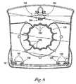
BACKGROUND
Cardiac arrest and ventricular fibrillation are examples of life-threatening medical conditions that may be treated with external defibrillation. External defibrillation includes applying electrodes to the patient's chest and delivering an electric shock to the patient to depolarize the patient's heart and restore normal sinus rhythm. The chances that a patient's heart can be successfully defibrillated increase significantly if a defibrillation shock is applied quickly.
A full-featured defibrillator is standard equipment for most modern hospitals. In many cases, hospitals mount the defibrillator on a mobile cart called a “crash cart.” A typical crash cart has several drawers that hold various instruments, medicines and supplies that are used by medical personnel. Some hospitals are equipped with several defibrillators mounted on crash carts. The crash carts may remain in a central location so that they may be quickly brought to the patient in need, wherever he or she may be.
Because a patient undergoing cardiac arrest or ventricular fibrillation has an urgent need, the defibrillator must be transported to the patient rapidly. A typical crash cart includes wheels so that it may be moved rapidly. In the rush to bring the defibrillator to the patient, there is a risk that the crash cart may swerve or collide with obstacles while being rushed to the patient. In such circumstances, it is important that the defibrillator not be accidentally dislodged from the crash cart.
Some hospital venues are very cramped, and a crash cart compounds the cramped conditions. When the defibrillator is mounted to the crash cart, it may be difficult to get the defibrillator close to the patient, or to orient the defibrillator so that it may be easily operated by the medical personnel.
SUMMARY
In general, the invention is directed to a docking station that can engage with a medical device such as a defibrillator. In a typical application, the docking station is mounted to a crash cart with fasteners such as bolts or screws. The medical device can easily be docked and undocked from the docking station. While docked, the medical device is held securely. Coupling mechanisms such as roller clamps engage the medical device and hold the device in place.
The medical device may also be rotated while docked. The docking station may include a base that is coupled to the crash cart and a platform that supports the medical device. The platform may have some freedom of rotation relative to the base, and the medical device may be rotated by rotating the platform.
In one embodiment, the invention is directed to a device comprising a platform, one or more coupling mechanisms and a base. In an exemplary embodiment described below, the platform is in the form of a “cover” supported by the base. The platform has some freedom to rotate relative to the base. The platform supports a medical device and the coupling mechanism engages and holds the medical device on the platform. The coupling mechanism may be, for example, a roller clamp. In an exemplary embodiment described below, three roller clamps hold the medical device, and one of the roller clamps is spring-loaded.
The device may include structure that assists the rotation of the platform relative to the base, such as a turntable. The device may also include structures that give the platform freedom to rotate in steps relative to the base.
In another embodiment, the invention is directed to a method. The method comprises engaging a medical device with a coupling mechanism on a docking station, holding the medical device with the coupling mechanism and rotating at least one portion of the docking station relative to another portion of the docking station. In an exemplary embodiment described below, the medical device may be held with a coupling mechanism such as a spring-loaded roller clamp. The roller clamp may retract when the coupling mechanism engages the medical device, and may extend to hold the medical device.
In a further embodiment, the invention is directed to a device comprising a platform, and at least two coupling mechanisms. The platform supports the medical device. The coupling mechanisms engage different sides of the medical device. The coupling mechanism may be, for example, roller clamps, and one or more of them may be spring-loaded. The device may also include a base coupled to the platform, the platform having some freedom to rotate relative to the base.
In an additional embodiment, the invention comprises a device comprising a platform and a base. Either the platform or the base is coupled to a crown, that is, a crown-like structure. The other of the platform and the base is coupled to a spring mechanism. The spring mechanism engages the crown. As a result, the rotation of the platform relative to the base is resisted by the engagement of the spring mechanism and the crown. Even though the rotational freedom of the platform relative to the base is restricted, the platform may have freedom to rotate 360 degrees relative to the base. Furthermore, the spring mechanism may deform when the platform is rotated relative to the base. In an exemplary embodiment described below, the spring mechanism and the crown cooperate to give the platform freedom to rotate in steps relative to the base.
In another embodiment, the invention is directed to an apparatus. The apparatus includes a crash cart, a base coupled to the crash cart and a platform coupled to the base. The platform supports a medical device and has some freedom to rotate relative to the crash cart.
In an added embodiment, the invention is directed to a defibrillator that includes docking structures that engage coupling mechanisms of a docking station. The docking structures may be, for example, recesses that correspond to the coupling mechanisms on the docking station.
The invention can provide one or more advantages, including security in transportation of a medical device. When docked to a docking station mounted to a crash cart, for example, the crash cart may be moved without dislodging the medical device from the crash cart. The medical device may easily be undocked from the docking station, which is advantageous in situations where the medical device needs to be taken to a place that cannot accommodate a crash cart.
While the medical device is docked to the docking station, the medical device can be rotated. It is not necessary to rotate the crash cart to orient the medical device in a desired direction. In one of the embodiments described below, the platform rotates in discrete steps relative to the base. Stepped rotational freedom prevents the medical device from swiveling uncontrollably when docked and also resists torques that may be applied when an operator operates the controls of the medical device.
The details of one or more embodiments of the invention are set forth in the accompanying drawings and the description below. Other features, objects, and advantages of the invention will be apparent from the description and drawings, and from the claims.
BRIEF DESCRIPTION OF DRAWINGS
FIG. 1 is a perspective view of a defibrillator engaged with a docking station.
FIG. 2 is a perspective view of the defibrillator ofFIG. 1 engaging or disengaging from the docking station.
FIG. 3 is a perspective view of the docking station of FIG.1.
FIG. 4 is a perspective view of the docking station ofFIG. 1 from a different angle, further demonstrating a mounting technique.
FIG. 5 is an exploded view of the docking station of FIG.1.
FIG. 6 is a perspective drawing of a spring arm that may be used in the docking station of FIG.1.
FIG. 7 is a perspective view of the underside of a cover associated with the docking station of FIG.1.
FIG. 8 is a plan view of the underside of a cover associated with the docking station of FIG.1.
FIG. 9 is a plan view of a crown on the underside of a cover associated with the docking station, engaged with the spring arm ofFIG. 6 in a stable configuration.
FIG. 10 is a plan view of a spring element of the spring arm ofFIG. 6 engaging the crown ofFIG. 9, with the spring arm in a stable configuration.
FIG. 11 is a plan view of the spring element ofFIG. 6 engaging the crown ofFIG. 9, with the spring arm in an unstable configuration.
FIG. 12 is a perspective view of a base of the docking station of FIG.1.
FIG. 13 is an exploded view of a front clamp.
FIG. 14 is a perspective view of the assembled and mounted front clamp of FIG.13.
FIG. 15 is an exploded view of a rear clamp.
DETAILED DESCRIPTION
FIG. 1 shows adefibrillator10 engaged with adocking station12.Docking station12 may be mounted to a crash cart (not shown in FIG.1), or similar structure. As will be shown below,defibrillator10 may be engaged with adocking station12 very quickly, and may also be disengaged fromdocking station12 quickly. When engaged withdocking station12,defibrillator10 is held securely bydocking station12, anddefibrillator10 may be transported rapidly on the crash cart without becoming dislodged. When disengaged fromdocking station12, however,defibrillator10 is portable and may be carried by ahandle14 to any convenient site.
As will be described in more detail below, the exterior ofdocking station12 principally comprises acover16 and abase18.Cover16 serves as a platform that supportsdefibrillator10.Base18 supports cover16.
Defibrillator10 engages coupling mechanisms (not shown in FIG.1), such as roller clamps, that are attached to cover16.Cover16 can rotate relative tobase18, which is stationary relative to the crash cart. As will be described below,base18 may be securely fastened to crash cart with fasteners such as screws, clamps, rivets or the like. By turningdefibrillator10, medical personnel rotatecover16 relative tobase18. In this way, medical personnel can rotatedefibrillator10 to a desired orientation on the crash cart.
In addition,base18 serves as a pedestal to elevatedefibrillator10 above the surface of the crash cart. In the exemplary application shown inFIG. 1,base18 raises cover16 about one inch (2.5 cm) above the surface of the crash cart. This extra space may accommodate cables and cords that may be attached todefibrillator10, and prevent the cables and cords from binding undercover16 whencover16 anddefibrillator10 are turned.
Notably, cover16 maintains a low profile.Cover16 preferably does not obstructdisplay20 or interfere with the operation of defibrillator controls22. Nor does cover16 interfere with front-mounted inputs or outputs, such aselectrocardiogram connector24,infrared data access26,defibrillator electrode receptacle28 orspeaker30. In the embodiment shown inFIG. 1, cover16 defines anotch32 that permits access to a built-inprinter34 ofdefibrillator10.Docking station12 therefore securesdefibrillator10 to the crash cart but does not interfere with the operation ofdefibrillator10.
FIG. 2 showsdefibrillator10 disengaging fromdocking station12. By lifting handle14 (not shown in FIG.2), an operator has caused afront clamp40 to disengage from arecess42 on the front side ofdefibrillator10.Defibrillator10 is still engaged to rear clamps (not shown in FIG.2), butdefibrillator10 can easily be disengaged from the rear clamps. Oncedefibrillator10 is disengaged fromdocking station12,defibrillator10 may be transported wherever desired. This is especially advantageous whendefibrillator10 is needed in an area too small to accommodate the crash cart, or when a patient is being transported on a gurney or mobile bed.
Asdefibrillator10 is lifted, thetop surface44 ofcover16 is revealed.Top surface44 is generally a flat surface that supports theunderside46 ofdefibrillator10. The mounting holes48 are unrelated to support ofdefibrillator10. Rather, mountingholes48 allowdocking station12 to be securely mounted to a crash cart or other structure, as will be shown in FIG.4.
FIG. 2 also shows one way in whichdefibrillator10 may engage withdocking station12. In particular, the operator may engage the rear ofdefibrillator10 with rear clamps first, thenlower defibrillator10 onto cover, engagingfront clamp40 withrecess42. This is not the only way fordefibrillator10 to engage withdocking station12, however. The operator may, for example, engagefront clamp40 first and the rear clamps afterward.
FIG. 3 is a perspective view ofdocking station12. The front side ofdocking station12 is indicated byreference numeral60 and the rear side is indicated byreference numeral62. As shown inFIG. 3, cover16 may include a substantially flat and substantially square-shapedtop surface44.Corners64,66,68,70 may bulge outward slightly to give the operator leverage to rotatecover16.Front ledge72 curves down slightly, thereby giving the operator extra room for access to front-mounted inputs or outputs ondefibrillator10, as shown in FIG.1.
Front clamp40 is housed byfront clamp housing74 incover16. As shown in FIG.3 and as will be described in more detail below,front clamp40 may comprise a spring-loaded roller clamp. Whendefibrillator10 is engaged or disengaged withdocking station12, the spring-loaded roller clamp may be pushed back intofront clamp housing74. When pressure against the spring-loaded roller clamp is released,front clamp40 projects outward fromfront clamp housing74.
Rear side62 includes a raisedbrim76. As shown inFIG. 3, brim76 may also wrap aroundcorners64,70.Brim76 may perform at least two functions. First, brim76 may house rear clamps78,80. Second, brim76 may provide a guide for the operator in steeringdefibrillator10 into engagement withdocking station12.Brim76 may be shaped to suit particular defibrillators. For example, brim76 includesnotch32, which gives the operator access to the built-inprinter34 indefibrillator10.Brim76 may be further shaped to accommodate power cables, data cables or other projections from a defibrillator.
FIG. 4 is a perspective view ofdocking station12 from another angle.FIG. 4 shows rear clamps78,80 housed inbrim76. Rear clamps78,80 may comprise roller clamps, and need not be spring-loaded. As will be described more fully below, rear clamps78,80 may be different fromfront clamp40, although the invention also encompasses the variation in which rear clamps78,80 andfront clamp40 are identically constructed.
FIG. 4 further illustrates a technique for mountingdocking station12 to acrash cart61 or other structure.Top surface44 includes three mountingholes48.Structure82 is not a mounting hole, but rather is a feature related to operation offront clamp40. A fastener such as ascrew84 is inserted into a mounting hole, which is large enough to accommodate the head ofscrew84. The head ofscrew84 therefore does not seat againsttop surface44. Mounting holes (not shown inFIG. 4) on the bottom side ofbase18 may be aligned with mountingholes48, but the mounting holes in the base are not large enough to accommodate the head ofscrew84. Whenscrew84 is driven into acrash cart61 or other structure with ascrewdriver86, the head ofscrew84 seats against the inner surface ofbase18, thereby mountingdocking station12 to thecrash cart61 or other structure.
Cover16 andbase18 may be formed from any of a number of materials, such as metal or plastic.Cover16 andbase18 may be formed from the same material or may be formed from different materials. In one embodiment, cover16 andbase18 are made from plastic and are injection molded from a blend of polycarbonate and acrylonitrile-butadiene-styrene resin, such as Bayblend™ plastic, commercially available from Bayer Corporation. Plastic of this type is easily molded, has good impact resistance and good rigidity and dimensional stability.
FIG. 5 is an exploded view that demonstrates the interior components and assembly ofdocking station12. The view ofcover16 inFIG. 5 is similar to the view ofcover16 in FIG.3, except that is lockingclamps40,78,80 are shown separately. Consequently, theopening88 in front clamphousing74, through which a portion of lockingclamp40 protrudes, is visible. Locking clamps40,78,80 will be described in more detail below.
Aturntable mechanism90, sometimes referred to conventionally as a “lazy susan bearing” or a “lazy susan turntable,” couples cover16 tobase18.Turntable mechanism90 comprises anupper platter92 and alower platter94 coupled to one another. Althoughplatters92,94 cannot be pulled apart,platters92,94 are free to rotate relative to one another. In a typical implementation,turntable90 includes a reduced friction mechanism, such as a ball bearing mechanism, to facilitate rotation.Turntable90 is typically constructed from metal, but can be fabricated of plastic for lighter loads.
Upper platter92 is coupled to cover16 with fasteners such as screws96.Lower platter94 is coupled tobase18 with fasteners such as screws98. Whencover16,turntable90 andbase18 are coupled in this fashion, cover16 cannot be separated frombase18, but cover16 andbase18 can be rotated relative to one another.Turntable90 further aids in weight distribution when a load such as the weight ofdefibrillator10 is placed uponcover16, allowing cover to rotate smoothly and without binding.
In one embodiment of the invention, cover16 andbase18 can be rotated relative to one another but the rotation is regulated. In particular, cover16 can rotate relative tobase18 through a number of stable positions. Aspring arm device100, coupled tobase18 as will be described below, interacts with a crown-shaped structure on the underside ofcover16 through acenter opening102 inturntable90 and regulates rotation. In particular,spring arm device100 interacts with the crown-shaped structure to provide a stepping action in whichturntable90 rotates among a series of locking angular positions. In the locking angular positions, cover16 resists rotation relative tobase18, but the resistance can be overcome by the application of sufficient torque. An applied torque of approximately three foot-pounds (approximately four newton-meters), for example, may be sufficient to rotatecover16 relative tobase18.
FIG. 6 is a perspective drawing ofspring arm100, which is an exemplary embodiment of a spring mechanism.Spring arm100 includes acentral body110.Central body110 may include acentral depression108.Main arms112,114 protrude fromcentral body110 in opposite directions.Central body110 andmain arms112,114 support fourspring elements116,118,120,122.Spring elements116,118,120,122 are arranged symmetrically.
Spring element116, for example, includes alarge spring member124 and asmall spring member126 coupled to acylinder128. In one embodiment,spring arm100 is made from plastic and are injection molded from Delrin™ acetal resin, commercially available from du Pont de Nemours and Company, of Wilmington, Del. Material of this kind produces a spring arm that can deform without fracturing or shattering. This material also has a low coefficient of friction, which promotes smooth interaction betweenspring arm100 and the underside ofcover16.
FIG. 7 is a perspective view of the underside ofcover16.Cover16 includes acrown130, which takes the form of a crown-shaped structure that receivesspring element100 as will be described below.Crown130 may be integrally formed withcover16.
FIG. 7 also shows supportingrib structure132, which provides structural integrity to cover16.Rib structure132 supportscrown130 and sleeves for mountingholes48.Rib structure132further supports fittings134 for fasteners96 (not shown inFIG. 7) that couple turntable90 (not shown inFIG. 7) to cover16.
Further,FIG. 7 showsopenings136,138 and mountingstructures140,142, which are used to mount rear clamps78,80.Cover16 also has anopening144, which forms the underside offront clamp housing74, andfront mounting structures146, which are used to mountfront clamp40.
FIG. 8 is a plan view of the underside ofcover16. This view shows the shape ofcrown130.Crown130 is a crown-shaped ring comprisingrounded indentations148 protruding into the ring.Rounded indentations148 definedetents150, which are the points insidecrown130 that are farthest from the center ofcrown130. InFIG. 8, there are sixteenindentations148 and sixteendetents150.
FIG. 9 shows the engagement betweencrown130 andspring arm100.Spring arm100 engagescrown130 in a stable configuration, i.e.,spring arm100 is as fully expanded insidecrown130 ascrown130 permits. In a typical implementation, the natural shape ofspring arm100seats spring arm100 snugly insidecrown130 with very little compression of any spring elements. In a stable configuration,spring elements116,118,120,122 exert very little force againstcrown130 because their shape is close to theshape spring elements116,118,120,122 would have whenoutside crown130. The engagement of foursymmetrical spring elements116,118,120,122 withcrown130 reduces wobbling during rotation. Notably,cylinder128 ofspring element116 need not necessarily rest fully in thenearest detent152.
FIGS. 10 and 11 illustrate compression ofexemplary spring element116 whenspring arm100 is rotated relative to crown130.FIG. 10 showsspring element116engaging crown130 in a stable configuration, andFIG. 11 showsspring element116engaging crown130 in an unstable configuration due to rotation. During rotation,indentation154 ofcrown130 pushescylinder128 closer tocentral body110. As a result,large spring member124 bends inward andsmall spring member126 deforms due to compression. The deformations store potential energy andcause cylinder128 to exert a greater force againstcrown130. Whencylinder128 nearsdetent156,large spring member124 andsmall spring member126push cylinder128 outward, and spring arm returns to a stable configuration.
As noted above,cylinder128 may be formed from a plastic such as Delrin™, andcrown130 may be formed from a plastic such as Bayblend™. There is a low coefficient of friction between such materials.Cylinder128 glides smoothly overindentation154 with little wear or tear to either component.
As will be shown below,spring arm100 is coupled tobase18 and does not rotate relative tobase18.Spring arm100 does rotate relative to cover16, however, as shown inFIGS. 9,10 and11, i.e.,crown130 rotates aroundspring arm100. In this way, the rotation ofcover16 relative tobase18 is not a smooth rotation. Rather, cover16 steps through sixteen stable positions. As a result,defibrillator10, when docked indocking station12, will not rotate freely. When crash cart is moved or is parked on an unbalanced surface,defibrillator10 will not swivel uncontrollably. Medical personnel can, however, apply a torque todefibrillator10 or cover16 to rotatedefibrillator10 to any desired angle.
FIG. 12 is a perspective view of the interior ofbase18. The center region includesbrackets160 that receivemain arms112,114 ofspring arm100. The center region may also include aprotrusion162, which is received bydepression108 ofcentral body110.
FIG. 12 furthershows mounting holes164.Base18 can be rotated relative to cover16 so that mountingholes164 align with mountingholes48 incover16. Mountingholes48 incover16 provide access to mountingholes164 inbase18. As shown inFIG. 4, a fastener such as ascrew84 may be seated against the inner surface ofbase18 to mountdocking station12 to a crash cart or other structure.
FIG. 12 also showssupport fittings166 for fasteners98 (not shown inFIG. 12) that couplelower platter94 of turntable90 (not shown inFIG. 7) tobase18. In addition,base18 may includeribs168 that receivelower platter94.Ribs168 are useful in aligninglower platter94 during assembly. Anaccess slot170 may allow the assembler to rotatelower platter94 into position for assembly.Base18 may also include arib structure172 for structural integrity and for support offittings166.
FIG. 13 is an exploded view of one of an exemplary coupling mechanism, i.e.,front clamp40.Front clamp40 includes aroller180 on aspindle182 that couples to arocker body184.Rocker body184 includes abracket186 that receivesroller180 andspindle182.Roller180 andspindle182 may be secured with alocking ring188.Rocker body184 is secured to front mountingstructures146 of cover16 (not shown inFIG. 13) with mountingbracket190 andfasteners192.Fasteners192 may be screws.
Rocker body184 includessockets194 that receiveexpansive springs196. In addition,rocker body184 includes anaxle member198 and astop block200.Rocker body184, includingsockets196,axle member198 and stopblock200, may be integrally formed form an injection molded plastic such as Delrin™.
FIG. 14 showsfront clamp40 assembled. When mounted to cover16,roller180 andbracket186 ofrocker body184 are protected byfront clamp housing74.Axle member198 seats in aslot202 defined by the underside ofcover16.Springs196 seat insockets194 and bear againstbarrier204, which likewise is defined by the underside ofcover16.Slot202 andbarrier204 are shown inFIGS. 7 and 8. Whencover16 is injection molded,barrier204 may be hollow, which may result in an artifact ontop surface44.Structure82, shown inFIGS. 3 and 4, is such an artifact.Springs196 push againstbarrier204 andsockets194, causingrocker body184 to pivot aroundaxle member198, thereby causingroller180 andbracket186 ofrocker body184 to project throughopening88. Stopblock200 bears against the underside ofcover16, impeding further projection throughopening88.
Front clamp40 is a spring-loaded roller clamp. Whendefibrillator10 is engaged withdocking station12,defibrillator10 pushesroller180 andbracket186 intofront clamp housing74. As a result,rocker body184 pivots aroundaxle member198, causingsprings196 to compress betweensockets196 andbarrier204. Whendefibrillator10 is docked, springs pushroller180 andbracket186 outward intorecess42 ofdefibrillator10. Similarly, whendefibrillator10 is disengaged fromdocking station12,defibrillator10 pushesroller180 andbracket186 intofront clamp housing74, androller180 andbracket186 spring back whendefibrillator10 is free.
FIG. 15 is an exploded view of an exemplaryrear clamp80.Rear clamp80 includes aroller210 on aspindle212 that couples to amain body214.Main body184 includes abracket216 that receivesroller210 andspindle212.Roller210 andspindle212 may be secured with alocking ring218.Main body214 may further include mountingbrackets220.Fasteners222 such as screwscouple mounting brackets220 to mountingstructures142 oncover16.Roller210 and a portion ofmain body184 protrude throughopening138 incover16.
Unlikefront clamp40,rear clamp80 is not spring loaded. Whendefibrillator10 engagesdocking station12 as shown inFIG. 2,defibrillator10 may engagerear clamps78,80 first, and need not pushrear clamps78,80 to make the engagement.
The invention can provide one or more advantages. In particular,docking station12 holdsdefibrillator10 securely.Defibrillator10 may be transported rapidly on a crash cart without becoming dislodged fromdocking station12. Other techniques for securing a defibrillator to a crash cart, such as strapping the defibrillator to the crash cart, prevent rapid removal of the defibrillator from the crash cart. When docked withdocking station12, by contrast,defibrillator10 may be quickly undocked fromdocking station12 for transportation to any convenient site.
Defibrillator10 can be rotated while docked indocking station12. In an embodiment described abovedefibrillator10 can be rotated 360 degrees. When dockingstation12 is mounted to a crash cart, it is less important to orient the crash cart so thatdefibrillator10 is facing in the right direction. Rather,defibrillator10 can simply be turned to a desired position by rotatingcover16 relative tobase18.
In one of the embodiments described above, cover16 rotates in discrete steps. Stepped rotational freedom is advantageous in many respects. First,defibrillator10 will not swivel uncontrollably when docked. Whendefibrillator10 is being rushed via a crash cart to a patient, uncontrolled swiveling is undesirable. Also, as shown inFIG. 1, controls22 ofdefibrillator10 may be located off-center, and operation of the controls may introduce torque todefibrillator10 anddocking station12. Torque may also be introduced by, for example, coupling defibrillation electrodes todefibrillator electrode receptacle28 and pulling the electrodes toward a patient. Without some restriction of rotational freedom,defibrillator10 may rotate to an inconvenient orientation and may be more difficult to operate. An operator may try to push a button, for example, only to havedefibrillator10 swivel in response. With stepped rotational freedom,docking station12 resists the applied torque, and the operator need not worry aboutcontrols22 moving. Access to inputs or outputs is also easier whendefibrillator10 is held steady. The particular embodiment employing a spring arm and a crown is further advantageous in that it uses few moving parts and requires no separate locking mechanism.
Although various coupling mechanisms may be employed, roller clamps are advantageous in several respects. Roller clamps need no separate locking latch. Roller clamps are also durable and can perform well after numerous dockings and undockings. Roller clamps also make docking and undocking simple: a medical device may be easily docked simply by pushing the medical device onto the docking station, and may be easily undocked by lifting the medical device off the docking station.
Various embodiments of the invention have been described. These embodiments are illustrative of the practice of the invention. Various modifications may be made without departing from the scope of the claims. For example, the docking station is not limited to use with a defibrillator. Other medical devices likewise may be secured to structures such as crash carts with the invention.
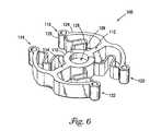
 Furthermore, cover16 is merely an exemplary platform for a defibrillator. Platforms may be shaped in a variety of ways, and in particular, may be shaped to accommodate and support a particular model of medical device. Similarly, the base need not be shaped likebase18. The invention encompasses docking stations with bases of all shapes.
The invention encompasses docking stations that include a platform that rotate in relation to a base. The invention encompasses all degrees of rotation, and is not limited to the stepped rotation described above. For example, a platform may rotate freely with respect to a base, and may also be locked in place with a mechanism such as a locking lever and/or a clutch mechanism.
The spring mechanism need not be a spring arm as shown in the figures. A spring mechanism may, for example, include fewer than four spring elements. It may be possible to form the spring element integrally with the platform or the base. Similarly, the crown need not be shaped as shown in the figures, and the spring mechanism need not engage the crown as shown. The spring mechanism may, for example, engage the exterior of the crown, rather than the interior as shown in FIG.9.
The crown may be coupled to the base, rather than the platform. Similarly, the spring mechanism may be coupled to the platform rather than the base.
The coupling mechanisms need not be roller clamps. The coupling mechanisms may be, for example, latches or manually operated locks. In an embodiment above, roller clamps on the docking station engaged recesses on a medical device, but the invention also encompasses, for example, roller clamps on a defibrillator that engage recesses on the docking station.
These and other embodiments are within the scope of the following claims.

Claims (32)

US10/091,6312002-03-042002-03-04Docking station for defibrillatorExpired - LifetimeUS6865418B2 (en)

Priority Applications (1)

Application NumberPriority DateFiling DateTitle
US10/091,631US6865418B2 (en)2002-03-042002-03-04Docking station for defibrillator

Applications Claiming Priority (1)

Application NumberPriority DateFiling DateTitle
US10/091,631US6865418B2 (en)2002-03-042002-03-04Docking station for defibrillator

Publications (2)

Publication NumberPublication Date
US20030167074A1 US20030167074A1 (en)2003-09-04
US6865418B2true US6865418B2 (en)2005-03-08

Family

ID=27804130

Family Applications (1)

Application NumberTitlePriority DateFiling Date
US10/091,631Expired - LifetimeUS6865418B2 (en)2002-03-042002-03-04Docking station for defibrillator

Country Status (1)

CountryLink
US (1)US6865418B2 (en)

Cited By (13)

* Cited by examiner, † Cited by third party
Publication numberPriority datePublication dateAssigneeTitle
US20040124979A1 (en)*2002-12-312004-07-01Medema Douglas K.Communication between emergency medical device and safety agency
US20040172069A1 (en)*2003-02-282004-09-02Hakala Douglas T.Recording information for emergency call by defibrillator apparatus
US20070154873A1 (en)*2005-12-292007-07-05Blevins Daniel AFacilitating medical emergency assistance
USD566282S1 (en)*2005-02-182008-04-08Masimo CorporationStand for a portable patient monitor
US20080108921A1 (en)*2006-11-072008-05-08Helgeson Lonnie JCombined air pulsator and movable pedestal
US20090013731A1 (en)*2007-07-132009-01-15Bo WeiFixing/releasing mechanism and the base using such mechanism
USD585991S1 (en)2006-11-072009-02-03Helgeson Lonnie JCombined air pulsator and movable pedestal
US20120246375A1 (en)*2009-07-242012-09-27Welch Allyn, Inc.Configurable health-care equipment apparatus
RU2542538C1 (en)*2013-11-192015-02-20Николай Евгеньевич СтароверовStationary system for nurse (versions)
JP2015513434A (en)*2012-03-042015-05-14メドトロニック アーディアン ルクセンブルク ソシエテ ア レスポンサビリテ リミテ Generator assembly and related systems and methods for neuromodulation therapy
US11920361B2 (en)2020-03-272024-03-05Physio-Control, Inc.Medical device docking station
US12102590B2 (en)2020-03-302024-10-01Zoll Medical CorporationMedical device system and hardware for sensor data acquisition
USD1063078S1 (en)*2018-08-162025-02-18Deka Products Limited PartnershipHandle of a central controller

Families Citing this family (16)

* Cited by examiner, † Cited by third party
Publication numberPriority datePublication dateAssigneeTitle
US7957798B2 (en)2003-12-172011-06-07Physio-Control, Inc.Defibrillator/monitor system having a pod with leads capable of wirelessly communicating
US10413742B2 (en)2008-03-052019-09-17Physio-Control, Inc.Defibrillator patient monitoring pod
US8929980B2 (en)2012-05-032015-01-06Physio-Control, Inc.External defibrillator electrode, method and system for reducing ECG artifact
US9289621B2 (en)*2012-05-082016-03-22Physio-Control, Inc.Defibrillator network system
US10099063B2 (en)*2012-07-022018-10-16Physio-Control, Inc.Medical monitor-defibrillator with defibrillator and data operations processors
US10303852B2 (en)2012-07-022019-05-28Physio-Control, Inc.Decision support tool for use with a medical monitor-defibrillator
US9026147B2 (en)2012-09-242015-05-05Physio-Control, Inc.Defibrillator location tracking device
US9282911B2 (en)2012-11-272016-03-15Physio-Control, Inc.Linear display of ECG signals
USD724218S1 (en)2012-11-302015-03-10Physio-Control, Inc.Defibrillator with bridge back and utility module
USD724219S1 (en)2012-11-302015-03-10Physio-Control, Inc.Utility module with a bridge back for receiving a defibrillator
JP2015150446A (en)*2014-02-182015-08-24ゾール メディカル コーポレイションZOLL Medical CorporationAutomated external defibrillator support mechanism
CN107106858A (en)*2014-12-102017-08-29皇家飞利浦有限公司 Emergency medical device that can be positioned at two different viewing angles and method for its positioning
USD781425S1 (en)*2016-02-262017-03-14Zoll Medical CorporationDefibrillator
JP6383775B2 (en)*2016-11-242018-08-29フクダ電子株式会社 Docking system
DE202017102531U1 (en)2017-04-282018-08-03Pöttker GmbH Swivel bearing for furniture
US10646170B2 (en)*2017-12-202020-05-12Drägerwerk AG & Co. KGaARotating docking station

Citations (24)

* Cited by examiner, † Cited by third party
Publication numberPriority datePublication dateAssigneeTitle
USD263995S (en)*1979-09-121982-04-20Providence HospitalCrash cart for hospitals
US4583795A (en)*1984-01-031986-04-22Brown Rollen ECrash cart for use in a hospital and the like
US5248264A (en)1992-05-081993-09-28Motorola, Inc.Latch assembly and carrier for a portable product
US5335651A (en)*1990-05-161994-08-09Hill-Rom Company, Inc.Ventilator and care cart each capable of nesting within and docking with a hospital bed base
US5375604A (en)1992-12-111994-12-27Siemens Medical Electronics, Inc.Transportable modular patient monitor
US5488537A (en)1994-03-281996-01-30Siemens Medical Systems, Inc.Safety interconnect latch for portable medical electronic patient monitoring product
US5765842A (en)*1996-07-241998-06-16Phaneuf; SimonMedical emergency treatment cart
US5829997A (en)1995-11-241998-11-03Victor Company Of JapanConnecting apparatus
US5876351A (en)1997-04-101999-03-02Mitchell RohdePortable modular diagnostic medical device
US5921697A (en)1995-08-311999-07-13Texas Instruments IncorporatedDocking station latch apparatus and attachment system
US5933321A (en)1996-10-181999-08-03Compaq Computer CorporationPortable computer docking station having modular motorized docking/undocking structure
US5946186A (en)1996-08-301999-08-31Texas Instruments IncorporatedLatch apparatus and attachment system
US5957838A (en)1996-07-021999-09-28Instrumentarium OyPatient monitoring system
US5997323A (en)1997-04-151999-12-07Samsung Electronic Co., Ltd.Device for connecting a portable computer to a docking station
US6163722A (en)*1997-11-142000-12-19Marquette Hellige GmbhDefibrillator having a monitor with rotatable screen content
US6183417B1 (en)1992-12-112001-02-06Siemens Medical Systems, Inc.Docking station for a patient monitoring system
US6185095B1 (en)1998-08-282001-02-06Hewlett-Packard CompanyComputer docking station with retractable release lever
US6221012B1 (en)1992-12-112001-04-24Siemens Medical Electronics, Inc.Transportable modular patient monitor with data acquisition modules
US6227518B1 (en)1999-09-082001-05-08Compal Electronics, Inc.Pivot base for a computer monitor
US6280212B1 (en)2000-04-182001-08-28Compaq Computer CorporationPortable computer docking station with movable docking connector
US6310766B1 (en)1997-03-152001-10-30Samsung Electronics Co., Ltd.Latching apparatus for a portable computer
US20030076015A1 (en)*2001-10-192003-04-24Ehrenreich Kevin J.Medical servicing system
US6594146B2 (en)*2000-12-262003-07-15Ge Medical Systems Information Technologies, Inc.Docking station for patient monitor or other electronic device
US6721178B1 (en)*1998-09-182004-04-13Fhs Acquisition, LlcMobile clinical workstation

Patent Citations (24)

* Cited by examiner, † Cited by third party
Publication numberPriority datePublication dateAssigneeTitle
USD263995S (en)*1979-09-121982-04-20Providence HospitalCrash cart for hospitals
US4583795A (en)*1984-01-031986-04-22Brown Rollen ECrash cart for use in a hospital and the like
US5335651A (en)*1990-05-161994-08-09Hill-Rom Company, Inc.Ventilator and care cart each capable of nesting within and docking with a hospital bed base
US5248264A (en)1992-05-081993-09-28Motorola, Inc.Latch assembly and carrier for a portable product
US5375604A (en)1992-12-111994-12-27Siemens Medical Electronics, Inc.Transportable modular patient monitor
US6221012B1 (en)1992-12-112001-04-24Siemens Medical Electronics, Inc.Transportable modular patient monitor with data acquisition modules
US6183417B1 (en)1992-12-112001-02-06Siemens Medical Systems, Inc.Docking station for a patient monitoring system
US5488537A (en)1994-03-281996-01-30Siemens Medical Systems, Inc.Safety interconnect latch for portable medical electronic patient monitoring product
US5921697A (en)1995-08-311999-07-13Texas Instruments IncorporatedDocking station latch apparatus and attachment system
US5829997A (en)1995-11-241998-11-03Victor Company Of JapanConnecting apparatus
US5957838A (en)1996-07-021999-09-28Instrumentarium OyPatient monitoring system
US5765842A (en)*1996-07-241998-06-16Phaneuf; SimonMedical emergency treatment cart
US5946186A (en)1996-08-301999-08-31Texas Instruments IncorporatedLatch apparatus and attachment system
US5933321A (en)1996-10-181999-08-03Compaq Computer CorporationPortable computer docking station having modular motorized docking/undocking structure
US6310766B1 (en)1997-03-152001-10-30Samsung Electronics Co., Ltd.Latching apparatus for a portable computer
US5876351A (en)1997-04-101999-03-02Mitchell RohdePortable modular diagnostic medical device
US5997323A (en)1997-04-151999-12-07Samsung Electronic Co., Ltd.Device for connecting a portable computer to a docking station
US6163722A (en)*1997-11-142000-12-19Marquette Hellige GmbhDefibrillator having a monitor with rotatable screen content
US6185095B1 (en)1998-08-282001-02-06Hewlett-Packard CompanyComputer docking station with retractable release lever
US6721178B1 (en)*1998-09-182004-04-13Fhs Acquisition, LlcMobile clinical workstation
US6227518B1 (en)1999-09-082001-05-08Compal Electronics, Inc.Pivot base for a computer monitor
US6280212B1 (en)2000-04-182001-08-28Compaq Computer CorporationPortable computer docking station with movable docking connector
US6594146B2 (en)*2000-12-262003-07-15Ge Medical Systems Information Technologies, Inc.Docking station for patient monitor or other electronic device
US20030076015A1 (en)*2001-10-192003-04-24Ehrenreich Kevin J.Medical servicing system

Cited By (21)

* Cited by examiner, † Cited by third party
Publication numberPriority datePublication dateAssigneeTitle
US7289029B2 (en)2002-12-312007-10-30Medtronic Physio-Control Corp.Communication between emergency medical device and safety agency
US20040124979A1 (en)*2002-12-312004-07-01Medema Douglas K.Communication between emergency medical device and safety agency
US20040172069A1 (en)*2003-02-282004-09-02Hakala Douglas T.Recording information for emergency call by defibrillator apparatus
USD566282S1 (en)*2005-02-182008-04-08Masimo CorporationStand for a portable patient monitor
US7567180B2 (en)*2005-12-292009-07-28Daniel Allen BlevinsFacilitating medical emergency assistance
US20070154873A1 (en)*2005-12-292007-07-05Blevins Daniel AFacilitating medical emergency assistance
US7713219B2 (en)2006-11-072010-05-11Electromed, Inc.Combined air pulsator and movable pedestal
USD585991S1 (en)2006-11-072009-02-03Helgeson Lonnie JCombined air pulsator and movable pedestal
WO2008057549A3 (en)*2006-11-072008-07-17Electromed IncCombined air pulsator and movable pedestal
US20080108921A1 (en)*2006-11-072008-05-08Helgeson Lonnie JCombined air pulsator and movable pedestal
US8430103B2 (en)2007-07-132013-04-30Ge Medical Systems Global Technology Company, LlcFixing/releasing mechanism and the base using such mechanism
US20090013731A1 (en)*2007-07-132009-01-15Bo WeiFixing/releasing mechanism and the base using such mechanism
US8499108B2 (en)*2009-07-242013-07-30Welch Allyn, Inc.Configurable health-care equipment apparatus
US20120246375A1 (en)*2009-07-242012-09-27Welch Allyn, Inc.Configurable health-care equipment apparatus
JP2015513434A (en)*2012-03-042015-05-14メドトロニック アーディアン ルクセンブルク ソシエテ ア レスポンサビリテ リミテ Generator assembly and related systems and methods for neuromodulation therapy
US20150297282A1 (en)*2012-03-042015-10-22Medtronic Ardian Luxembourg SarlGenerator assemblies for neuromodulation therapy and associated systems and methods
RU2542538C1 (en)*2013-11-192015-02-20Николай Евгеньевич СтароверовStationary system for nurse (versions)
USD1063078S1 (en)*2018-08-162025-02-18Deka Products Limited PartnershipHandle of a central controller
US11920361B2 (en)2020-03-272024-03-05Physio-Control, Inc.Medical device docking station
US12320136B2 (en)2020-03-272025-06-03Physio-Control, Inc.Medical device docking station
US12102590B2 (en)2020-03-302024-10-01Zoll Medical CorporationMedical device system and hardware for sensor data acquisition

Also Published As

Publication numberPublication date
US20030167074A1 (en)2003-09-04

Similar Documents

PublicationPublication DateTitle
US6865418B2 (en)Docking station for defibrillator
ES2957686T3 (en) security device
US6845723B2 (en)Folding and tilting table
US7828253B2 (en)Secure shelf for technology workstand
US20050045072A1 (en)Adjustable height workstation for laptop or tablet computers
JP4531263B2 (en) Computer display screen system, adjustable display screen mount and swivel display screen for display screen system
US9527456B2 (en)Device for retaining flat, approximately rectangular appliances such as tablet computers or mobile telephones in the interior of a motor vehicle
US6721178B1 (en)Mobile clinical workstation
US7274564B2 (en)Locking cradle for tablet computers
EP1176935B1 (en)Docking assembly
US20100213679A1 (en)Accessory Cart
US11332177B2 (en)Charging and storage cart with accessory mounting system and method
US8662458B2 (en)Infusion management system and holder
US20240159068A1 (en)Medical device docking station
US11919556B2 (en)Cart for medical equipment
WO2004057144A2 (en)Laptop security device
US7137603B2 (en)Apparatus for providing desktop mobility for desktop electronic devices
US20080079292A1 (en)Organizer attachable to a chair and task utility system and process of providing same
KR101674369B1 (en)Portable folding table with monolithic structure
EP4287421B1 (en)Medical device accessories
WO2015161238A2 (en)Portable medical cart system
CN217091647U (en) Medical fluid pump, load holding device and load holding system
CN115227519B (en)Carrier and oxygenator system using same
US20100012796A1 (en)Mobile Cart Laptop Computer Retainer and Stand System
JP4878749B2 (en) Thin display hanging device and furniture with thin display hanging device

Legal Events

DateCodeTitleDescription
ASAssignment

Owner name:MEDTRONIC PHYSIO-CONTROL CORP., WASHINGTON

Free format text:ASSIGNMENT OF ASSIGNORS INTEREST;ASSIGNOR:MERRY, RODNEY;REEL/FRAME:012679/0140

Effective date:20020228

STCFInformation on status: patent grant

Free format text:PATENTED CASE

CCCertificate of correction
FPAYFee payment

Year of fee payment:4

ASAssignment

Owner name:PHYSIO-CONTROL, INC., WASHINGTON

Free format text:CHANGE OF NAME;ASSIGNOR:MEDTRONIC EMERGENCY RESPONSE SYSTEMS, INC.;REEL/FRAME:027009/0086

Effective date:20061201

Owner name:MEDTRONIC EMERGENCY RESPONSE SYSTEMS, INC., WASHIN

Free format text:CHANGE OF NAME;ASSIGNOR:MEDTRONIC PHYSIO-CONTROL CORP.;REEL/FRAME:027009/0050

Effective date:20040415

ASAssignment

Owner name:BANK OF NEW YORK MELLON TRUST COMPANY, N.A., AS *C

Free format text:SECURITY AGREEMENT;ASSIGNOR:PHYSIO-CONTROL, INC.;REEL/FRAME:027765/0861

Effective date:20120130

ASAssignment

Owner name:CITIBANK, N.A., AS COLLATERAL AGENT, NEW YORK

Free format text:SECURITY AGREEMENT;ASSIGNOR:PHYSIO-CONTROL, INC.;REEL/FRAME:027763/0881

Effective date:20120130

FPAYFee payment

Year of fee payment:8

ASAssignment

Owner name:PHYSIO-CONTROL, INC., WASHINGTON

Free format text:RELEASE BY SECURED PARTY;ASSIGNOR:THE BANK OF NEW YORK MELLON TRUST COMPANY, N.A.;REEL/FRAME:037519/0240

Effective date:20150605

ASAssignment

Owner name:CITIBANK, N.A., AS COLLATERAL AGENT, NEW YORK

Free format text:FIRST LIEN SECURITY AGREEMENT;ASSIGNORS:PHYSIO-CONTROL, INC.;PHYSIO-CONTROL INTERNATIONAL, INC.;REEL/FRAME:037532/0828

Effective date:20150605

ASAssignment

Owner name:CITIBANK, N.A., AS COLLATERAL AGENT, NEW YORK

Free format text:SECOND LIEN SECURITY AGREEMENT;ASSIGNORS:PHYSIO-CONTROL, INC.;PHYSIO-CONTROL INTERNATIONAL, INC.;REEL/FRAME:037559/0601

Effective date:20150605

ASAssignment

Owner name:PHYSIO-CONTROL, INC., WASHINGTON

Free format text:RELEASE BY SECURED PARTY;ASSIGNOR:CITIBANK, N.A.;REEL/FRAME:038376/0806

Effective date:20160405

Owner name:PHYSIO-CONTROL INTERNATIONAL, INC., WASHINGTON

Free format text:RELEASE BY SECURED PARTY;ASSIGNOR:CITIBANK, N.A.;REEL/FRAME:038379/0001

Effective date:20160405

Owner name:PHYSIO-CONTROL, INC., WASHINGTON

Free format text:RELEASE BY SECURED PARTY;ASSIGNOR:CITIBANK, N.A.;REEL/FRAME:038379/0001

Effective date:20160405

Owner name:PHYSIO-CONTROL, INC., WASHINGTON

Free format text:RELEASE BY SECURED PARTY;ASSIGNOR:CITIBANK, N.A.;REEL/FRAME:038378/0028

Effective date:20160405

Owner name:PHYSIO-CONTROL INTERNATIONAL, INC., WASHINGTON

Free format text:RELEASE BY SECURED PARTY;ASSIGNOR:CITIBANK, N.A.;REEL/FRAME:038378/0028

Effective date:20160405

FPAYFee payment

Year of fee payment:12


[8]ページ先頭

©2009-2025 Movatter.jp