US6865237B1 - Method and system for digital signal transmission - Google Patents
Method and system for digital signal transmissionDownload PDFInfo
- Publication number
- US6865237B1 US6865237B1US09/676,373US67637300AUS6865237B1US 6865237 B1US6865237 B1US 6865237B1US 67637300 AUS67637300 AUS 67637300AUS 6865237 B1US6865237 B1US 6865237B1
- Authority
- US
- United States
- Prior art keywords
- code
- matrix
- symbols
- matrices
- antennas
- Prior art date
- Legal status (The legal status is an assumption and is not a legal conclusion. Google has not performed a legal analysis and makes no representation as to the accuracy of the status listed.)
- Expired - Lifetime, expires
Links
- 238000000034methodMethods0.000titleclaimsabstractdescription63
- 230000008054signal transmissionEffects0.000titledescription2
- 239000011159matrix materialSubstances0.000claimsabstractdescription233
- 238000004891communicationMethods0.000claimsdescription10
- 230000015572biosynthetic processEffects0.000abstractdescription4
- 230000005540biological transmissionEffects0.000description28
- 239000013598vectorSubstances0.000description28
- 238000013461designMethods0.000description18
- 238000001514detection methodMethods0.000description14
- 238000005562fadingMethods0.000description13
- 239000000243solutionSubstances0.000description12
- 238000012545processingMethods0.000description9
- 238000007476Maximum LikelihoodMethods0.000description6
- 230000011664signalingEffects0.000description6
- 230000009466transformationEffects0.000description6
- 230000001413cellular effectEffects0.000description5
- 238000010276constructionMethods0.000description5
- 230000006698inductionEffects0.000description5
- 238000001228spectrumMethods0.000description5
- 238000004422calculation algorithmMethods0.000description4
- 230000008859changeEffects0.000description4
- 238000010295mobile communicationMethods0.000description4
- 230000000694effectsEffects0.000description3
- 230000006870functionEffects0.000description3
- 229910052704radonInorganic materials0.000description3
- 230000007480spreadingEffects0.000description3
- 238000004458analytical methodMethods0.000description2
- 238000013459approachMethods0.000description2
- 238000005284basis setMethods0.000description2
- 230000001427coherent effectEffects0.000description2
- 230000004044responseEffects0.000description2
- 230000003068static effectEffects0.000description2
- 239000000654additiveSubstances0.000description1
- 230000000996additive effectEffects0.000description1
- QELSIJXWEROXOE-UHFFFAOYSA-Nasoxime chlorideChemical compound[Cl-].[Cl-].C1=CC(C(=O)N)=CC=[N+]1COC[N+]1=CC=CC=C1\C=N\OQELSIJXWEROXOE-UHFFFAOYSA-N0.000description1
- 230000008901benefitEffects0.000description1
- 238000004364calculation methodMethods0.000description1
- 230000015556catabolic processEffects0.000description1
- 230000021615conjugationEffects0.000description1
- 238000012937correctionMethods0.000description1
- 238000006731degradation reactionMethods0.000description1
- 230000001066destructive effectEffects0.000description1
- 239000010432diamondSubstances0.000description1
- 238000010790dilutionMethods0.000description1
- 239000012895dilutionSubstances0.000description1
- 238000005516engineering processMethods0.000description1
- 238000001914filtrationMethods0.000description1
- 238000011835investigationMethods0.000description1
- 238000007726management methodMethods0.000description1
- 238000012067mathematical methodMethods0.000description1
- 238000012986modificationMethods0.000description1
- 230000004048modificationEffects0.000description1
- 239000013307optical fiberSubstances0.000description1
- 239000002245particleSubstances0.000description1
- 230000010363phase shiftEffects0.000description1
- 230000008569processEffects0.000description1
- 230000000644propagated effectEffects0.000description1
- SYUHGPGVQRZVTB-UHFFFAOYSA-Nradon atomChemical compound[Rn]SYUHGPGVQRZVTB-UHFFFAOYSA-N0.000description1
- 238000012552reviewMethods0.000description1
- 238000000926separation methodMethods0.000description1
- 239000007787solidSubstances0.000description1
- 238000012549trainingMethods0.000description1
- 238000000844transformationMethods0.000description1
Images


Classifications
- H—ELECTRICITY
- H04—ELECTRIC COMMUNICATION TECHNIQUE
- H04B—TRANSMISSION
- H04B7/00—Radio transmission systems, i.e. using radiation field
- H04B7/02—Diversity systems; Multi-antenna system, i.e. transmission or reception using multiple antennas
- H04B7/04—Diversity systems; Multi-antenna system, i.e. transmission or reception using multiple antennas using two or more spaced independent antennas
- H04B7/06—Diversity systems; Multi-antenna system, i.e. transmission or reception using multiple antennas using two or more spaced independent antennas at the transmitting station
- H04B7/0613—Diversity systems; Multi-antenna system, i.e. transmission or reception using multiple antennas using two or more spaced independent antennas at the transmitting station using simultaneous transmission
- H04B7/0667—Diversity systems; Multi-antenna system, i.e. transmission or reception using multiple antennas using two or more spaced independent antennas at the transmitting station using simultaneous transmission of delayed versions of same signal
- H04B7/0669—Diversity systems; Multi-antenna system, i.e. transmission or reception using multiple antennas using two or more spaced independent antennas at the transmitting station using simultaneous transmission of delayed versions of same signal using different channel coding between antennas
- H—ELECTRICITY
- H04—ELECTRIC COMMUNICATION TECHNIQUE
- H04L—TRANSMISSION OF DIGITAL INFORMATION, e.g. TELEGRAPHIC COMMUNICATION
- H04L1/00—Arrangements for detecting or preventing errors in the information received
- H04L1/02—Arrangements for detecting or preventing errors in the information received by diversity reception
- H04L1/06—Arrangements for detecting or preventing errors in the information received by diversity reception using space diversity
- H04L1/0618—Space-time coding
Definitions
- This inventionrelates generally to methods and systems for achieving transmit diversity in a telecommunication system. More particularly, the present invention relates to an apparatus and associated method for using a space-time block code to reduce bit error rates of a wireless communication in a spread spectrum receiver.
- a vectormay be represented in Dirac notation proposed by P.A.M. Dirac:
- ⁇ z( 1 0 0 - 1 )
- ⁇ x( 0 1 1 0 )
- ⁇ ⁇ ⁇ y( 0 - i i 0 )
- a set of linearly independent vectorsmay be represented as group elements, a vector space may be generated by taking a linear combination of the elements of the set.
- the product already defined on the basis setcan be extended to all the elements of the vector space by linearity defining a group algebra.
- the Pauli-Spin matricesmay be thought of as group elements.
- wireless system designhas become increasingly demanding in relation to equipment and performance requirements.
- Future wireless systemswhich will be third generation (3G) systems and fourth generation systems compared to the first generation analog and second generation digital systems currently in use, will be required to provide high quality high transmission rate data services in addition to high quality voice services.
- Concurrent with the system service performance requirementswill be equipment design constraints, which will strongly impact the design of mobile terminals.
- the third and fourth generation wireless mobile terminalswill be required to be smaller, lighter, more power-efficient units that are also capable of providing the sophisticated voice and data services required of these future wireless systems.
- Time-varying multi-path fadingis an effect in wireless systems whereby a transmitted signal propagates along multiple paths to a receiver causing fading of the received signal due to the constructive and destructive summing of the signals at the receiver. This occurs regardless of the physical form of the transmission path, (i.e. whether the transmission path is a radio link, an optical fiber or a cable).
- Several methodsare known for overcoming the effects of multi-path fading, such as time interleaving with error correction coding, implementing frequency diversity by utilizing spread spectrum techniques, transmitter power control techniques, and the like. Each of these techniques, however, has drawbacks in regard to use for third and fourth generation wireless systems.
- Time interleavingmay introduce unnecessary delay
- spread spectrum techniquesmay require large bandwidth allocation to overcome a large coherence bandwidth
- power control techniquesmay require higher transmitter power than is desirable for sophisticated receiver-to-transmitter feedback techniques that increase mobile station complexity. All of these drawbacks have negative impact on achieving the desired characteristics for third and fourth generation mobile terminals.
- Diversityis another way to overcome the effects of multi-path fading.
- Antenna diversityis one type of diversity used in wireless systems.
- antenna diversitytwo or more physically separated antennas are used to receive a signal, which is then processed through combining and switching to generate a received signal.
- a drawback of diversity receptionis that the physical separation required between antennas may make diversity reception impractical for use on the forward link in the new wireless systems where small mobile station size is desired.
- a second technique for implementing antenna diversityis transmit (Tx) diversity.
- Txtransmit
- a signalis transmitted from two or more antennas and then processed at the receiver by using maximum likelihood sequence estimator (MLSE) or minimum mean square error (MMSE) techniques.
- MSEmaximum likelihood sequence estimator
- MMSEminimum mean square error
- Transmit diversityhas more practical application to the forward link in wireless systems in that it is easier to implement multiple antennas in the base station than in the mobile terminal.
- FIG. 1is an illustration showing an example of a transmit diversity system.
- Channel interferencemay be created by structures or other features 140 among various channel paths.
- Space-Time Block Codeaka Space-Time Code (STC) may be considered as diversity-creating.
- the essential design criteriaare the achieved diversity, the rate of the code, and the delay.
- Diversityis characterized by the number of independently decodable channels. For full diversity, this equals the number of transmit antennas.
- the rate of the codeis the ratio of the space-time coded transmission rate to the rate of an one-antenna transmission (i.e. the ratio of the transmission rate of the block code to transmission rate of the uncoded scheme).
- the delayis the length of the space-time block code frame.
- space-time block codesmay be divided into real and complex codes.
- Rate in the context of space-time block codemay be understood as inefficiency in use of the antenna resources, leading to dilution of maximal bit-rates as compared to the inherent capacity of the underlying wireless system specifications.
- This inefficient use of antenna resourcesmay give rise to fluctuating of transmit powers.
- Such fluctuation of transmit powersis referred to as the power-unbalance problem.
- the aim of diversityis to achieve maximal diversity.
- AlamoutiAn example of an open-loop concept is provided by Alamouti, who proposed a method of transmit diversity employing two antennas that offers second order diversity for complex valued signals.
- S. M. Alamouti“ A Simple Transmit Diversity Technique for Wireless Communications,” IEEE Journal on Selected Areas of Communications , vol. 16, no. 8, pp. 1451-1458, October 1998 and publication WO 99/14871 of ALAMOUTI et al. entitled “Transmitter Diversity Technique for Wireless Communication”
- Tsymbol period
- s 1 and s 2are complex numbers.
- the signal ⁇ s 2 *(negation/conjugate)is transmitted from the first antenna (Tx 1 ) and the signal s 1 * (conjugate) is transmitted from the second antenna (Tx 2 ), where * is the complex conjugate operator.
- 21.
- Cis the code matrix
- Iis the identity matrix of the same dimension
- His the hermitean operator (complex conjugate transpose).
- the maximum-ratio-combining property of the codeis a direct consequence of the appearance of the sum of the symbol powers on the main diagonal of the hermitean square of the code matrix.
- the Alamounti STBCis the Radon-Hurwitz submatrix form and is an unitary unimodular matrix given in general form by:
- C R ⁇ ⁇ H[ c n c n + 1 - c n + 1 * c n * ] ( 10 )
- This methodhas a disadvantage in a loss in transmission rate and the fact that the multi-level nature of the ST coded symbols increases the peak-to-average ratio requirement of the transmitted signal and imposes stringent requirements on the linear power amplifier design.
- a drawback of the above solutionsis that only the requirements 1 and 2 can be fulfilled.
- the transmission power of different antennasis divided unequally, (i.e. different antennas transmit at different powers). This causes problems in the planning of output amplifiers.
- the code rateis not optimal.
- this maximal rateis 3 ⁇ 4. Because of the inefficiency of codes with rates less than one (R ⁇ 1) transmit power of a given antenna fluctuates in time; thus, presenting a power-unbalanced problem. Therefore, there is a need to provide a power-balance full-rate code. Since a decrease in rate may not acceptable, some other features of space-time block codes have to be relaxed.
- the STOTD schemeis completely balanced and is also orthogonal, so that linear decoding gives maximal likelihood results.
- the diversity order achievedis only two, which is the same as the Alamouti STTD scheme.
- D ceshould have full rank for all distinct code words c and e.
- the eigenvalues of D ce H D ceshould be as close to each other as possible.
- Tr ⁇ ⁇ D ce H ⁇ D ce ⁇N ⁇ ⁇ k ⁇ ⁇ z k , c - z k , e ⁇ 2 . This is the maximum given a fixed transmit power. Moreover, all eigenvalues are the same.
- a method of transmitting a digital signal consisting of symbolswhich method comprises the steps of coding complex symbols to channel symbols in blocks having the length of a given K and transmitting the channel symbols via several different channels and two or more antennas.
- codingis performed such that the coding is defined by a code matrix, which can be expressed as a sum of 2K elements, in which each element is a product of a symbol or symbol complex conjugate to be transmitted and a N ⁇ N representation matrix of a complexified anti-commutator algebra, extended by a unit element, and in which each matrix is used at most once in the formation of the code matrix.
- the codingis performed such that the coding is defined by a code matrix which is formed by freely selecting 2K ⁇ 1 unitary, anti-hermitean N ⁇ N matrices anti-commuting with each other, forming K ⁇ 1 pairs of said matrices, whereby the remaining matrix forms a pair with an N-dimensional unit matrix, forming two matrices of each pair such that the second matrix of the pair, multiplied by the imaginary unit, is added to and subtracted from the first matrix of the pair, and in which each matrix formed in the above manner defines the dependence of the code matrix on one symbol or symbol complex conjugate to be coded.
- the inventionalso relates to an arrangement for transmitting a digital signal consisting of symbols, which arrangement comprises a coder for coding complex symbols to channel symbols in blocks having the length of a given K, means for transmitting the channel symbols via several different channels and two or more antennas.
- the coderis arranged to code the symbols using a code matrix, which can be expressed as a sum of 2K elements, in which each element is a product of a symbol or symbol complex conjugate to be transmitted and a a N ⁇ N representation matrix of a complexified anti-commutator algebra, extended by a unit element, and in which each matrix is used at most once in the formation of the code matrix.
- the coderis arranged to code the symbols using a code matrix which is formed by freely selecting 2K-1 unitary, anti-hermitean N ⁇ N matrices anti-commuting with each other, forming K ⁇ 1 pairs of said matrices, whereby the remaining matrix forms a pair with an N-dimensional unit matrix, forming two matrices of each pair such that the second matrix of the pair, multiplied by the imaginary unit, is added to and subtracted from the first matrix of the pair, and in which each matrix formed in the above manner defines the dependence of the code matrix on one symbol or symbol complex conjugate to be coded.
- the solution of the inventioncan provide a system in which any number of transmit and receive antennas can be used and a full diversity gain can be achieved by space-time block coding.
- the maximal code rate and the optimal delayare achieved by square codes having a dimension that is a power of two.
- the solution of the inventionemploys complex block codes.
- codesare used, which are based on matrices whose all elements have the form of ⁇ s k , ⁇ s* k or 0.
- the prior art solutionsreveal no codes in whose elements the term 0 appears.
- square codesare given, from which non-square codes are obtained by eliminating columns (antennas).
- these codesknown as basic codes the elements depend only on one symbol, or on the real part of a symbol and the imaginary part of another symbol.
- full diversity codeswhich do not have the above restriction can be used.
- a code matrixis formed by matrices of a portion of the symbols placed on the diagonal of the code matrix and by matrices of a second portion of symbols along the anti-diagonal of the code matrix.
- a sub-optimal solutionis also provided by an embodiment of the invention using a rate 1 ⁇ 3 convolution code.
- the solution of the inventionpreferably also provides coding in which the ratio of the maximum power to the average power or the ratio of the average power to the minimum power can be minimized.
- the transmitted symbolsmay be recovered using a maximum likelihood sequence estimator (MLSE) decoder implemented with the Viterbi algorithm with a decoding trellis according to the transmitter.
- MSEmaximum likelihood sequence estimator
- FIG. 1shows an example of a system of multi-channel transmission in which multi-path path fading may occur
- FIG. 2Ashows an example of a system in accordance with an embodiment of the invention
- FIG. 2Bshows another example of a system in accordance with an embodiment of the invention
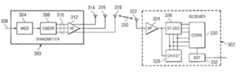
- FIG. 3is an illustration showing an example of a transmitter/receiver arrangement in accordance with an embodiment of the invention
- FIG. 4shows a rate ⁇ fraction (5/16) ⁇ two-layer block code for four antennas
- FIG. 5shows a rate ⁇ fraction (63/64) ⁇ three-layer block code for four antennas.
- FIGS. 6A & 6Bshow the two forms of matrices from which a power-balanced full rate code may be constructed.
- the inventionmay be used in radio systems which allow the transmission of at least a part of a signal by using at least three or more transmit antennas or three or more beams that are accomplished by any number of transmit antennas.
- a transmission channelmay be formed by using a time division, frequency division or code division multiple access method.
- systems that employ combinations of different multiple access methodsare in accordance with the invention.
- the examplesdescribe the use of the invention in a universal mobile communication system utilizing a broadband code division multiple access method implemented with a direct sequential technique, yet without restricting the invention thereto.
- a structure of a mobile communication systemis described by way of example.
- the main parts of the mobile communication systemare core network CN, UMTS terrestrial radio access network UTRAN and user equipment UE.
- the interface between the CN and the UTRANis called lu and the air interface between the UTRAN and the UE is called Uu.
- the UTRANcomprises radio network subsystems RNS.
- the interface between the RNSsis called lur.
- the RNScomprises a radio network controller RNC and one or more nodes B.
- the interface between the RNC and Bis called lub.
- the coverage area, or cell, of the node Bis marked with C in the figure.
- FIG. 2AThe description of FIG. 2A is relatively general, and it is clarified with a more specific example of a cellular radio system in FIG. 2 B.
- FIG. 2Bincludes only the most essential blocks, but it is obvious to a person skilled in the art that the conventional cellular radio system also includes other functions and structures, which need not be further explained herein. It is also to be noted that FIG. 2B only shows one exemplified structure. In systems according to the invention, details can be different from what is shown in FIG. 2B , but as to the invention, these differences are not relevant.
- a cellular radio networktypically comprises a fixed network infrastructure, i.e. a network part 200 , and user equipment 202 , which may be fixedly located, vehicle-mounted or portable terminals.
- the network part 200comprises base stations 204 , a base station corresponding to a B-node shown in the previous figure.
- a plurality of base stations 204are, in turn, controlled in a centralized manner by a radio network controller 206 communicating with them.
- the base station 204comprises transceivers 208 and a multiplexer 212 .
- the base station 204further comprises a control unit 210 which controls the operation of the transceivers 208 and the multiplexer 212 .
- the multiplexer 212arranges the traffic and control channels used by several transceivers 208 to a single transmission connection 214 , which forms an interface lub.
- the transceivers 208 of the base station 204are connected to an antenna unit 218 which is used for implementing a bi-directional radio connection 216 to the user equipment 202 .
- the structure of the frames to be transmitted in the bi-directional radio connection 216is defined separately in each system, the connection being referred to as an air interface Uu.
- the radio network controller 206comprises a group switching field 220 and a control unit 222 .
- the group switching field 220is used for connecting speech and data and for combining signalling circuits.
- the base station 204 and the radio network controller 206form a radio network subsystem 224 which further comprises a transcoder 226 .
- the transcoder 226is usually located as close to a mobile services switching center 228 as possible, because speech can then be transferred in a cellular radio network form between the transcoder 226 and the radio network controller 206 , which saves transmission capacity.
- the transcoder 226converts different digital speech coding forms used between a public switched telephone network and a radio network to make them compatible, for instance from a fixed network form to another cellular radio network form, and vice versa.
- the control unit 222performs call control, mobility management, collection of statistical data and signalling.
- FIG. 2Bfurther shows the mobile services switching center 228 and a gateway mobile services switching center 230 which controls the connections from the mobile communications system to the outside world, in this case to a public switched telephone network 232 .
- a sub-optimal class of Space-Time Codesbased on the Radon-Hurwitz sub-matrix.
- the inventioncan thus be applied particularly to a system in which signal transmission is carried out by using complex space-time block coding in which the complex symbols to be transmitted are coded to channel symbols in blocks having the length of a given K in order to be transmitted via several different channels and two or more antennas. These several different channels can be formed of different time slots.
- the symbol blockforms into a code matrix in which the number of columns corresponds to the number of antennas used for the transmission and the number of rows corresponds to the number of different channels, which, in case of space-time coding, is the number of time slots to be used.
- the inventioncan be applied to a system in which different frequencies or different spreading codes are used instead of time slots. In this case it does not naturally deal with space-time coding but rather with space-frequency coding or space-code-division coding.
- the space-frequency codingcould be used in an OFDM (orthogonal frequency division multiplexing) system, for example.
- the present inventionminimizes the inherent non-orthogonality and have simple linear decoding, which may be iterated.
- the present inventionis also backward compatible with 3GPP release 99 open-loop diversity mode.
- a square complex space-time block codeis based on a unitary N ⁇ N matrix, whose elements depend on linearly transmitted symbols s k and their complex conjugates.
- a unitary matrixis a square matrix whose inverse matrix is proportional to its hermitean conjugate.
- the hermitean conjugateis the complex conjugate of the matrix transpose.
- the proportional coefficient between the product of the code matrix and its hermitean conjugate, and the unit matrixis a linear combination of the absolute value squares of the symbols to be transmitted. This linear combination can be called unitarity coefficient.
- the unitarity (complex-orthogonality) of the space-time block codesmay thus be expressed with the inner products proportional to the sum of the squared amplitudes of the symbols:
- C H ⁇ C⁇ i ⁇ ⁇ z i ⁇ 2 ⁇ I ( 19 )
- Cis the code matrix
- Iis the identity matrix of the same dimension
- His the hermitean conjugate (complex conjugate transpose operator).
- the maximum-ratio-combining property of the codeis a direct consequence of the appearance of the sum of the symbol powers on the diagonal of the hermitean square of the code matrix.
- a vector spacemay be generated by taking a linear combination of the elements of the set.
- the product already defined on the basis setcan be extended to all the elements of the vector space by linearity.
- this prescriptionyields all possible complex linear space-time codes with N antennas and time epochs, full diversity, and rate K/N.
- the codes with minimal dimensions for a given rateare thus delay optimal codes.
- An embodiment of the inventionprovides a sub-optimal solution as will be presented below.
- Matrices (28)are proportional to Pauli matrices. For later convenience, these have been chosen so that ⁇ 1 and or ⁇ 2 are anti-hermitean, and ⁇ 3 is hermitean.
- the fundamental representation(the minimal dimension faithful representation), is generated by these 2 ⁇ 2 matrices.
- j ⁇ 1 ⁇ 2 ⁇ 3 ⁇ 4 ⁇ 5is an hermitean/Casimir operator, and its matrix representation can be taken proportional to the unit matrix.
- ⁇ 5⁇ j ⁇ 1 ⁇ 2 ⁇ 3 ⁇ 4 .
- R K ( ⁇ tilde over ( ⁇ ) ⁇ K ⁇ 1 )R 2 ( ⁇ 1 ) ⁇ circle around ( ⁇ ) ⁇ I dim
- R K ( ⁇ tilde over ( ⁇ ) ⁇ K )R 2 ( ⁇ 2 ) ⁇ circle around ( ⁇ ) ⁇ I dim R K ⁇ 2 (35)
- R K ⁇ ( ⁇ K )j ( K + 1 ) / 2 ⁇
- R K - 1 ⁇ ( ⁇ j1 K - 1 ⁇ ⁇ ⁇ j ) ( 39 )
- the induction steps abovecan be used to prove the following theorem:
- the minimal dimension to represent a Clifford algebra generated by K elementsis 2 [K/2] .
- R 2 (su 2 )is the fundamental two-dimensional representation of su 2 , the algebra of anti-hermitean 2 ⁇ 2 matrices with vanishing trace.
- ⁇ tilde over (R) ⁇denotes this representation space enlarged by matrices proportional to the two-dimensional unit matrix.
- An anti-hermitean matrixrefers to a matrix, the hermitean conjugate of which is the matrix itself multiplied by ⁇ 1.
- Anti-commutationmeans that when two matrices can be multiplied by each other in two orders, then if one product is ⁇ 1 times the other product, the matrices anti-commute.
- the above family, to which 2K ⁇ 1 matrices belong,can be called an N-dimensional anti-commutator algebra presentation of 2K ⁇ 1 elements.
- a code matrixis formed such that each of the matrices formed as above defines the dependence of the code matrix on one and only one s k or the complex conjugate of s k .
- the code matrixis the sum of 2K elements and each element is the product of some s k or s k complex conjugate and an N ⁇ N complex anti-commutator matrix, such that each symbol, complex conjugate, and matrix only appears once in the expression.
- the matricesform an anti-commutator algebra presentation of the freely selected 3 elements.
- Two matricesare selected from the above defined matrices, and they can be called an elementary pair.
- the remaining matrixis multiplied by the imaginary unit, and the result is called a third elementary matrix.
- a matrix proportional to a two-dimensional unit matrixis used as a fourth elementary matrix. This matrix can be called an elementary unit matrix.
- K-I pairs of N ⁇ N matricesare formed of these matrices by formulating tensor products of K ⁇ 1 elementary matrices for example in the following manner:
- the second matrix pairis obtained by tensoring K ⁇ 3 elementary matrices, one member of the elementary pair and the third elementary matrix, in this order.
- the Ith matrix pairis obtained by tensoring K-I ⁇ 1 elementary unit matrices, one member of the elementary pair and I ⁇ 1 third elementary matrices, in this order.
- K-1th pairis obtained by tensoring one member of the elementary pair and K ⁇ 2 third elementary matrices.
- the tensor product of two matricescan be understood as a block form by considering a matrix with as many blocks as the first matrix to be tensored has elements, each block being as big as the second matrix to be tensored.
- a block of the tensor productis the corresponding element of the first matrix times the second matrix.
- the obtained codeis a delay optimal basic block code.
- All possible basic block codes of a given code ratecan be created simply by interchanging the places of rows and/or columns in all ⁇ matrices simultaneously, or by multiplying the ⁇ matrices by any combination of terms, or changing the numbering of the ⁇ matrices, or by multiplying all ⁇ matrices from right and/or left by a unitary matrix which has four elements diverging from zero, the elements being an arbitrary combination of the numbers ⁇ 1, ⁇ i.
- the basic rate 3 ⁇ 4 code for four transmit antennas as formed in the above mannerhas the form ( s 1 , s 2 , s 3 ) ⁇ ( s 1 s 2 s 3 0 - s 2 * s 1 * 0 - s 3 - s 3 * 0 s 1 * s 2 0 s 3 * - s 2 * s 1 ) ( 49 )
- the rate 1/2 code for eight antennasis ( s 1 , s 2 , s 3 ) ⁇ ( s 1 s 2 s 3 0 s 4 0 0 0 - s 2 * s 1 * 0 - s 3 0 - s 4 0 0 - s 3 * 0 s 1 * s 2 0 0 - s 4 0 0 s 3 * - s 2 * s 1 0 0 0 s 4 - s 4 * 0 0 0 0 s 1 * s 2 s 3 0 0 s 4 * 0 0 - s 2 * s 1 0 - s 3 0 0 s 4 * 0 0 - s 2 * s 1 0 - s 3 0 0 s 4 * 0 - s 3 * 0 - s 3 * 0 - s 1 * s 1 * s 2 0 0 - s 4
- rate 3 ⁇ 4 codeis in the upper left corner and the corresponding inverted complex conjugate in the lower right corner.
- This constructiongives a family of block codes with N 2 +N′ 2 ⁇ 2 continuous parameters.
- the square codes obtained this waycomprise delay optimal maximal rate block codes when the number of antennas is proportional to a power of two.
- usersmay be provided with different versions (for example, a version with a permutated antenna order) of the block code, and thus the transmission powers can be uniformized.
- the signal received by the antenna m at the time slot tis denoted by r tm .
- FIG. 3is an illustration of an arrangement according to an embodiment of the invention—to be use as exemplar only.
- the figureshows a situation where channel-coded symbols are transmitted via three antennas at different frequencies, at different time slots or by using a different spreading code.
- a transmitter 300which is in connection with a receiver 302 .
- the transmittercomprises a modulator 304 which receives as input a signal 306 to be transmitted, which consists of bits in a solution according to a preferred embodiment of the invention.
- the bitsare modulated to symbols in the modulator.
- the symbols to be transmittedare grouped into blocks having the length of a given K. It is assumed in this example that the length of the block is three symbols and that the symbols are s 1 , s 2 and s 3 .
- the symbolsare conveyed to a coder 308 .
- each blockis coded to N ⁇ N′ channel symbols.
- the channel symbols 310are conveyed in this example via radio frequency parts 312 to three antennas 314 to 318 from where they are to be transmitted.
- the blockcomprises the symbols s 1 , s 2 and s 3 .
- the coderperforms coding, the defining code matrix of which is formed of 2K elements, in which each element is a product of a symbol or symbol complex conjugate to be transmitted and a complex N ⁇ N anticommutator matrix, and in which each matrix is used at most once in the formation of the code matrix.
- a code matrixcan for example be the matrix (54) described above, which means that the coder performs the coding ( s 1 , s 2 , s 3 ) ⁇ ( s 1 - s 2 * - s 3 * s 1 * + s 2 * + s 3 * s 1 * - s 2 * + s 3 * s 1 + s 2 - s 3 s 1 + s 2 * - s 3 * - s 1 * + s 2 * - s 3 * - s 1 * + s 2 * + s 3 * - s 1 + s 2 + s 3 * - s 1 + s 2 + s 3 * - s 1 + s 2 + s 3 s 1 - s 2 * + s 3 * s 1 * + s 2 * - s 3 * - s 1 * + s 2 * + s 3 * s 1 * + s 2 * - s 3 * - s 1 *
- the codercan preferably be implemented by means of a processor and suitable software or alternatively by means of separate components.
- a signal 320is transmitted by using three or more antennas.
- the signalis received in the receiver 302 by means of an antenna 322 and it is conveyed to the radio frequency parts 324 .
- the signalis converted to an intermediate frequency or to baseband.
- the converted signalis conveyed to a channel estimator 326 , which forms estimates for the channel through which the signal has propagated.
- the estimatescan be formed, for example, by means of previously known bits the signal contains, such as a pilot signal or a training sequence code.
- the signalis conveyed from the radio frequency parts also to a combiner 328 , to which also the estimates are delivered from the channel estimator 326 .
- the channel estimator and the radio frequency partscan be implemented by employing the known methods.
- a detector 330performs the symbol detection according to the formula (61). The signal is conveyed from the detector 330 to a channel decoder 332 and further to the other parts of the receiver.
- the detectorcan preferably be implemented by means of a processor and suitable software or alternatively by means of separate components.
- space-time block codesmay be relaxed.
- One such featureis the requirement of orthogonality of the space-time block code.
- rates less than 1result in power-unbalanced schemes (i.e. the transmit power of a given antenna fluctuates in time).
- the basic rate 3 ⁇ 4 codeis given above, the symbols transmitted are s 1 , s 2 , and s 3 .
- a three antenna version of the codeis derived by switching off one of the antennas. The inefficiency and power-unbalance is visible in the zeros of the code. Furthermore, it is clear from the code that the inefficiency of the code is due to the existence of redundant directions in the code matrix, which are not used for signaling.
- Layered space-time block codesinvolves patching pieces of fully orthogonal space-time block codes together.
- ⁇is the matrix of channel weights (allowing for a multitude of receive antennas)
- Ris the matrix of received symbols
- the inefficiency of the codeis exploited to transmit additional data.
- parts of another block code(the higher layer code) may be appended onto the redundant directions of the block code. This is repeated as many time as is required to transmit the full higher layer code.
- the upper layersviolate the inherent orthogonality of the underlying block code, making linear one-step decoding impossible.
- the two-layer codecan be decoded in two linear steps, first the upper layer, then, after interference cancellation, the component codes of the lower layer one at a time. Better performance is achieved, if instead of linear decoding, the upper layer is decoded by a optimal configuration search.
- the possible residual inefficiency of the two-layer codecan be used to transmit a third layer block code.
- the linear decoding of a I-layer codehas to be done in I steps, starting from the uppermost layer.
- the interference induced by a higher layer on the lower onesis cancelled after detection of the higher layer.
- the best performanceis achieved when the upper layers are decoded by a optimal configuration search.
- Code matrix orthogonalityrestricts the number of symbols to some number K ⁇ N.
- the proposed schemeapplies when K ⁇ N.
- the antenna resourceis used inefficiently, the block code has rate ⁇ 1, and it is power-unbalanced.
- the received symbol vectoris a vector in N-dimensional complex space, call it the reception space.
- orthogonality of the code matrixwhich translates on reception to linear decodability of the block code, and full diversity.
- the code-matrix-orthogonal K symbolsspan a K-dimensional subspace of the reception space, call it the block-code reception subspace.
- K ⁇ Nthere is room in the reception space for more information.
- This extra informationis called the higher layer, and it is encoded into redundant directions of the code matrix, (i.e. code matrix directions that project onto directions of the reception space that are reception-space-orthogonal to the block-code reception subspace).
- This reception-space-orthogonalitydoes not translate into code-matrix orthogonality, as the latter was already maximized when maximizing K. Thus one-step linear decoding is lost. However, the redundant directions can be decoded first, and subtracted using interference cancellation. After this, what remains from the received symbols, can be linearly decoded using code-matrix orthogonality. Optimal decoding of the upper layer requires searching through the upper layer configurations to find the optimal one.
- the additional layeringcan be terminated on any stage (also before adding any layers to the basic block code), and the remaining inefficiency can be used to transmit known pilot bits. These dedicated pilots would, apart from improving the channel estimates on reception, make the code completely power-balanced. Also, a rate-1 block code (Alamouti 2 ⁇ 2 or no code) can be used on an upper layer to make the layered code unit rate and power-balanced.
- a rate-1 block codeAlamouti 2 ⁇ 2 or no code
- the upper layer codescan be designed so that it is possible to construct upper layer pseudo-received signals in which the interference from the lower layers is cancelled completely. These pseudo-received signals are constructed from the received signals and the powers of the estimated channels.
- the upper-layer codecan thus be decoded directly, without considering lower-layer interference.
- the decoded upper layercan then be cancelled from the received signals, and the lower layer may be decoded linearly. This decoding scheme is sensitive to changes in the channels over the whole multi-layer block.
- the upper-layer decoding based on pseudo-received symbolsis sub-optimal, however.
- An optimal upper-layer decodingwould involve searching the upper layer configuration which after IC and lower-layer decoding would give the smallest euclidean distance between the received signals and the explained part of the received signals.
- An optimal decodingis insensitive to changes in the channels between lowest layer sub-blocks.
- the optimal decodingcan be approached by iterating an IC-procedure.
- the transmitted symbolsare divided into two parts, the lowest layer and the upper ones.
- the detected lowest and upper layer symbolsare alternately subtracted from the received signals, using the residual signal to detect the upper and lowest layer symbols, respectively.
- the lowest layer of a two-layer codeconsists of four elementary blocks.
- the processing delayis 16 symbol intervals. All in all, 15 complex symbols can be encoded into a two-layer block code with three or four transmit (Tx) antennas.
- This equationis the basis of the layering embodiment of the invention.
- the zeros in the lower layer blocksare filled with rows from the higher layer block code.
- a matrixis added that can be constructed as the product of the redundance spanner matrix ⁇ 0 , and a matrix with one of the rows of C 2 on the diagonal.
- the zeros in the two-layer code in FIG. 4may now be used to accommodate either pilot bits, or one row of a third layer block code. Repeating this four times, for each row of the Layer 3 block, we get a rate ⁇ fraction (63/64) ⁇ three-layer block code for four transmit (Tx) antennas. This code provides full diversity, and encodes 63 complex symbols with a processing delay of 64.
- An example of a three-layer codeis given in FIG. 5 .
- the procedure of inserting rows of the third layer code into holes of the two-layer codesdiffers from inserting rows of the second layer to the one-layer codes, in that no sign changes indicated by multiplying with ⁇ 0 are required.
- the residual inefficiency of these codescan be used to transmit pilot symbols. This would make the codes completely power-balanced.
- the decoding algorithmsare presented for one receive (Rx) antenna. It is easy to generalize to any number of Rx antennas.
- An optimal decodinginvolves an upper layer configuration search.
- An optimal decodingis insensitive to changes of the channels between successive lowest layer blocks.
- the layered schemethus is as sensitive to the fading speed as the lowest-layer block code.
- This embodiment of the inventionprovides an iterative IC-procedure that converges towards optimal decoding for the 2-layer code in FIG. 4 .
- the complex channel weights between the n:th transmit and the receive antennais denoted ⁇ n .
- each of these subblockscan be decoded as a 4 ⁇ 4 block code of the form C 3/4 , using metric (65) above.
- each received signalcarries information of only one of the upper layer symbols, multiplied by a channel. It is clear how these can be maximal ratio combined by multiplying with suitable channel estimates. Due to the space-time block code structure of the upper layer, MRC gives four-diversity-branch combined estimates for the symbols.
- the linear I-step decoding described in the next Sectioncan be used as a starting point for iterative IC detection, making convergence faster.
- iterative IC detectionFor fast fading channels, one should start the iterations by first detecting the lowest layer with no IC.
- An embodiment of the inventionprovides for a detection and interference cancellation procedure, which decodes in I-linear steps the preferred embodiment I-layered code built on space-time block code C 3/4 .
- the channelsare supposed to be almost static over the I-layer processing period of length 2 21 .
- the pseudo-received symbols constructed in (70)carry the data encoded onto the redundant directions of the four first layer blocks.
- M k 2
- MAPmaximum a posteriori
- the interferenceis only one-way; the upper layer bits disturb the lower layer bits, whereas the upper layer does not see the lower layer.
- this procedureis iterated the corresponding number of times, always starting from the highest layer.
- R 3[ ⁇ ⁇ 1 4 ⁇ s 61 + ⁇ 2 4 ⁇ s 62 + ⁇ 3 4 ⁇ s 63 ⁇ 2 4 ⁇ s 61 * - ⁇ 1 4 ⁇ s 62 * - ⁇ 4 4 ⁇ s 63 ⁇ 3 4 ⁇ s 61 * + ⁇ 4 4 ⁇ s 62 - ⁇ 1 4 ⁇ s 63 * ⁇ 4 4 ⁇ s 61 - ⁇ 3 4 ⁇ s 62 * + ⁇ 2 4 ⁇ s 63 * ] + noise ( 82 )
- M k 3
- each of these blocksmay be decoded with the metric (78), and again, after second-layer IC, the sixteen first-layer blocks may be decoded using metric (65).
- the decoding of the I:th layerproceeds in a similar way, only that in constructing the I:th layer pseudo-received symbols, as in (76, 81), the channel vector ⁇ (2I ⁇ 2) is used, and in the I:th layer metric, corresponding to (78, 83), the channel vector ⁇ (2I ⁇ 2) is used.
- the rate of a layered codecan be increased even more than by using the same code on all layers.
- the price to pay for thisis performance losses due to non-coherent combining of upper layer channels.
- a two-step linear decoding of this codestarts with creating a second layer pseudo-received symbol, as in Equation (76), then making a symbol decision for s 4 based upon this pseudo-received symbol, subtracting the interference from the lower layer, (i.e. s 1 ; s 2 ; s 3 ), and decoding them as a normal block code.
- An optimal decodinginvolves searching through the 16 upper layer configurations, canceling the interference of these, decoding the lower layer using metric (65), and choosing the configuration which minimizes the residual noise.
- the non-orthogonality determined by the procedure set out abovemeasures ⁇ fraction (3/16) ⁇ or 0.1875.
- the layered block code methodis an iterative decoding that is based on interference cancellation between the fully orthogonal pieces of the layered code. It rapidly approaches the optimal performance provided by a maximum likelihood decoder.
- the co-pending applicationalso provides a non-orthogonal four-antenna space-time block code based on a matrix of size 16 ⁇ 4, (i.e. it had a processing delay of 16 symbol periods or time epochs), with a rate equal to ⁇ fraction (15/16) ⁇ .
- the non-orthogonality of the codemeasures ⁇ fraction (2/25) ⁇ or 0.08.
- FIGS. 6A and 6Bshow the two forms of matrices from which a power-balanced full rate code may be constructed.
- any of the hollow circles 610is some phase factor times s 1 or s 1 *; any of the stars 620 is some phase factor times s 2 or s 2 *; any of the solid circles 630 is some phase factor times s 3 or s 3 *; and any of the diamonds 640 is some phase factor times s 4 or s 4 *.
- the germinal matricesi.e. the parts of the code matrix depending only on one of the symbols, are all unitary matrices by default).
- full raw diversity four-antenna codecan be mapped to one of the two forms shown in FIGS. 6A and 6B by discrete matrix operations like interchanging columns and/or rows. These operations do not affect performance properties. Also, generic unitary transformations may be applied from left and/or right, changing the power spectrum, but leaving the performance unchanged.
- the four symbolsmay be arranged as follows replacing the complex (z) representation in the general sub-matrix form with (s) to represent the symbol to be transmitted.
- C ABBA ⁇ ( s 1 , s 2 , s 3 , s 4 )[ ⁇ s 1 s 2 s 3 s 4 - s 2 * s 1 * - s 4 * s 3 * s 3 s 4 s 1 s 2 - s 4 * s 3 * - s 2 * s 1 * ⁇ ] . ( 89 )
- C ABBAhas two of the 2 ⁇ 2 Alamouti block code with symbols s 1 and s 2 on the block diagonal, and has two copies of the Alamounti code with symbols s 3 , s 4 on the block anti-diagonal in the form [ A B B A ] . ( 91 )
- This embodimentmay be referred to as the “ABBA” scheme.
- the common channel pilotsare organized in a suitable way.
- LMMSELeast Minimal Mean Squares Estimate
- H[ ⁇ ⁇ 1 ⁇ 2 ⁇ 3 ⁇ 4 ⁇ 2 * - ⁇ 1 * ⁇ 4 * - ⁇ 3 * ⁇ 3 ⁇ 4 ⁇ 1 ⁇ 2 ⁇ 4 * - ⁇ 3 * ⁇ 2 * - ⁇ 1 * ⁇ ] ( 95 )
- H [ ⁇ R 1 R 2 * R 3 R 4 * ⁇ ]( ( ⁇ 1 ⁇ ⁇ 1 * + ⁇ 2 ⁇ ⁇ 2 * + ⁇ 3 ⁇ ⁇ 3 * + ⁇ 4 ⁇ ⁇ 4 * ) ⁇ l + N ⁇ ) [ ⁇ s 1 s 2 s 3 s 4 ⁇ ] + noise . ( 96 )
- N2 ⁇ jIm ⁇ [ s 1 ⁇ s 3 * + s 2 ⁇ s 4 * ] [ ⁇ 0 0 1 0 0 0 0 1 1 0 0 0 0 1 0 0 ⁇ ]
- ⁇ ⁇ N2 ⁇ ⁇ Re ⁇ [ s 1 ⁇ s 3 * + s 2 ⁇ s 4 * ] [ ⁇ 0 0 1 0 0 0 0 1 1 0 0 0 0 0 ⁇ ] . ( 97 )
- iterative methodsmay be used to improve the estimates of correlating symbols.
- onemay subtract from the received symbols the estimates of symbols s 3 and s 4 , then detect the (orthogonally encoded) symbols s 1 and s 2 , and vice versa.
- most of the benefitmay be reaped with one re-iteration only.
- Another way to build embodiments of the inventionis to restrict the non-orthogonality to be block diagonal instead of the block off-diagonal non-orthogonality (97) of the preferred embodiment.
- a ⁇ ( s1 , s2 )[ s 1 s 2 ⁇ s 2 ⁇ s 1 ] ( 101 )
- delay optimal minimally non-orthogonal space-time block codesmay be constructed by repeatedly iterating the ABBA method.
- An embodiment of the inventionprovides a class of sub-optimal space-time block codes.
- Z 12[ z 1 z 2 - z 2 * z 1 * ] .
- Z 12[ z 1 z 2 - z 2 * z 1 * ] .
- H[ h 1 h 2 h 2 * - h 1 * ] . matrix, the attention will be focused on the latter one. Subsequently, a few proprieties of H matrix are given below.
- C 2k ⁇ 1,2k and D 2k ⁇ 1,2kare p ⁇ p matrices that:
- H (1)has nonzero entries in all positions. Therefore a multi-user detector, which may include de-correlating and decision-feedback, should be employed for data estimation. However, if relations (102) or (103) (above) could be exploited, the number of nonzero entries in H (1) can be halved. This will significantly reduce the cross-interference terms, thus improving the detector performance.
- the number of nonzero entries in H (1)can be halved if relation (116) holds for any (i,j) pair.
- Relation (121)provides the first data estimates (first stage).
- the next stage(s)can use y (1) from relation (119) and the previous stage data estimations to cancel the interference given by the b elements in H (1) the matrix.
- the computation overhead introduced by MICis insignificant because H (1) is a sparse matrix.
- a sparse matrixis a matrix where the number of nonzero elements situated off the main diagonal is less than the number of zero elements.
- bis a real value thus, multiplication with ⁇ 1 ⁇ j is as a matter of fact a change of sign.
- the estimationcan be performed using hard bit or soft bit decision.
- the algorithmcan provide soft outputs, which is desirable for the next processing blocks, (e.g. convolutional decoder).
- S[ ⁇ s 1 s 2 s 3 s 4 s 3 s 4 s 1 s 2 - s 2 * s 1 * - s 4 * - s 3 * - s 4 * - s 3 * - s 4 * - s 3 * - s 2 * - s 1 * ⁇ ] ( 124 )
- phase rotationscan be applied to antennas. Recall that the columns are associated with the antennas. Therefore if a phase rotation is applied to all the elements of a given column, this will translate as a phase rotation to the corresponding channel, and implicitly to the corresponding antenna. This can be useful to combat the degradation due to the fading.
Landscapes
- Engineering & Computer Science (AREA)
- Computer Networks & Wireless Communication (AREA)
- Signal Processing (AREA)
- Radio Transmission System (AREA)
- Mobile Radio Communication Systems (AREA)
Abstract
Description
- Bra a| which may be represented by a row matrix or αi=[α1,α2,α3]
- Ket |b which may be represented by a column matrix
and - C is defined as
a|b=b|a*
a|(β|b+γ|c)=βa|b+γa|c
a|a≧0, anda|a=0iff|a=0.
- but
(the Kronecker delta δij) is a symbol that is defined to be 0 for i≠j and to be 1 when i=j and can be represented by the unit matrix
which may also be referred to as the identity matrix I2or for an N dimension basis IN. The vectors i and j are normalized and form an orthonormal basis. Sometimes {|ei}i=1Nis used as a basis in a N-dimensional vector space.
- but
- |b=A|a operator A performs operation on vector state |a to produce vector state |b,
- b|A|a*=a|AH|b where AHis an operator whose matrix elements are AijH=(Aji) and is called Hermitian when AH=A.
- |b=A|a operator A performs operation on vector state |a to produce vector state |b,
∃ε∈G ε*g=g*ε=gand∀g∈G,∃g−1g*g−1=g−1*g=ε
- which reads in other words: there exist an unique element ε of the group G such that ε operating on g equals g operating on ε equals g (the element ε is referred to as the identity); and for every element g belonging to group G, there exists an element g−1(called the inverse) such that g operating on g-inverse equals g-inverse operating on g equals the identity ε.
| TABLE 1 | |||
| Period | Trans. Ant. 1 (Tx1) | Trans Ant. 2 (Tx2) | Receive Ant. (Rx) |
| T1 | s1 | s2 | r1 |
| T2 | −s2* | s1* | r2 |
r1=h1s1+h2s2+n1 (1)
r2=−h2s2*+h1s1*+n2* (2)
- where n1and n2are noise factors and let us assume impulse response coefficients, e.g. flat-fading case hi, where i=1 to K associated with the two antennas (K=2) are constant over the two-symbol time interval.
is optimal with complex signal constellations. It reaches diversity 2, with a linear decoding scheme which yields estimates for both symbols with the two channels maximal ratio combined.
and the received signals by
and the noise by
- or, equivalently,
- or, equivalently,
s=H12Hr (6)
ŝ=sign (H12Hr)=sign[(||h1||2+||h2||2)I2s+H12Hn] (7)
where a and b are complex numbers which satisfy the unimodular condition |a|2+|b|2=1. The orthogonality of the space-time block codes may thus be expressed as
- where a star (*) refers to a complex conjugate. These codes are not delay-optimal.
- 1. Full diversity in regard to the number of antennas.
- 2. Only linear processing is required in a transmitter and a receiver.
- 3. Transmission power is divided equally between the antennas.
- 4. The code rate efficiency is as high as possible.
- 1. The rank criterion: The diversity gained by a multiple transmitter scheme is:
diversity=mine≠cRank[Dce]<=min[T;N] (14)
- 1. The rank criterion: The diversity gained by a multiple transmitter scheme is:
- 2. The determinant criterion: To optimize performance in a Rayleigh fading environment, Code (C) should be designed to maximize
mine≠sdet′[DceHDce]. (15)
- 2. The determinant criterion: To optimize performance in a Rayleigh fading environment, Code (C) should be designed to maximize
- 3. The trace criterion: To optimize performance in flat fading channels, Code (C) should be designed to maximize the Euclidean distance
Tr[DceHDce]. (16)
- 3. The trace criterion: To optimize performance in flat fading channels, Code (C) should be designed to maximize the Euclidean distance
- Rank criterion: As an unitary matrix, Dceis full rank for all distinct code word pairs. Thus, all space-time block codes give full diversity, equaling the number of Tx antennas.
This is the maximum given a fixed transmit power. Moreover, all eigenvalues are the same.
βkHβj+βjHβk=2δjkIN. (23)
γk=βkHβk;k=0, . . . ,2K−1, (24)
γkH=−γk,k=1, . . . ,2K−1, (25)
γkγj+γjγk=−2δjkIN,j,k=1, . . . ,2K−1. (26)
γkγj
- 1. Find a N-dimensional representation of the Clifford algebra γkγj+γjγk=−2δjkIN,j,k=1 . . . ,2K −1 for anti-hermitean matrices γk, k=1, . . . ,2K−1.
- 2. Take an unitary matrix β0εU(N).
- 3. Define βk=β0γk,k=1, . . . ,2K−1.
- 4. Use the matrices βk,k=0, . . . ,2K−1 to create a code matrix C(z) according
γ1=σ1; γ2=σ2. (29)
γ3=γ1γ2=Iσ3. (30)
Here we see that Clifford3coincides with the algebra su2. Also, Clifford2is a two-dimensional sub-algebra of su2.
to be the above representation of the three generators of Clifford3, together with the two-dimensional unit matrix, we get exactly the 2×2 Alamouti code. Next add a fourth generator to the Clifford-algebra. Denoting {tilde over (γ)}3=−jγ1γ2γ3, {tilde over (γ)}4=−jγ1γ2γ4, we see from the anti-commutation relations that the sub-algebras generated by γ1, γ2and {tilde over (γ)}3, {tilde over (γ)}4commute. The two sub-algebras, on the other hand, are isomorphic to Clifford2. Thus each of these subalgebras can be represented using the matrices in Equation (A.27). The two commuting sub-algebras, however, have to be represented using the tensor product. Thus, we get the following matrix representation for the generators of Clifford4:
γ1=I2{circle around (×)}σ1;γ2=I2{circle around (×)}σ2{tilde over (γ)}3=σ1{circle around (×)}I2;{tilde over (γ)}4=σ2{circle around (×)}I2. (31)
- using prescription
one can use the matrices above with the indices cyclically permuted.
- using prescription
{tilde over (γ)}K=(−j)K/2−1(Πi=1K−2γj)γK,
{tilde over (γ)}K−1=(−j)K/2−1(Πi=1K−2γj)γK−1. (34)
RK(γj)=I2{circle around (×)}RK−2(γj)j=1, . . .K−2
RK({tilde over (γ)}K−1)=R2(γ1){circle around (×)}IdimRK−2
RK({tilde over (γ)}K)=R2(γ2){circle around (×)}IdimRK−2 (35)
RK(γj)=RK−1(γj),j=1, . . .K−1 (38)
γj→VHγjV,j=1 . . . ,L (42)
where V is an unitary dimRK×dimRKmatrix. This symmetry is large enough to accommodate any choice of basis in Clifford2sub-algebras.
- where the dimensions of the commuting sub-algebra representation (d1, . . . ,d[K/2]) are even integers ≧2.
- matrices are anti-hermitean and unitary; and
- matrices anti-commute with each other.
- The first matrix pair is established as a tensor product of K−2 elementary unit matrices and members of the elementary pair. Each member of the elementary pair appears as separately tensored with the unit matrices. This gives two matrices, (i.e. a matrix pair).
- is used, which is called an elementary unit matrix.
{overscore (C)}=UC(s)V, (51)
- where C(s) is a basic block code, such as above. It is an N×N′ matrix, where N is the number of time slots and N′ is the number of antennas. U and V are N×N and N′×N′ unitary matrices. The phase shifts caused by U and V are irrelevant. U and V can be assumed to be unitary matrices with
determinant 1.
- where C(s) is a basic block code, such as above. It is an N×N′ matrix, where N is the number of time slots and N′ is the number of antennas. U and V are N×N and N′×N′ unitary matrices. The phase shifts caused by U and V are irrelevant. U and V can be assumed to be unitary matrices with
- where the exp operation is a matrix exponential, the six parameters ωkare complex and the three parameters Φkare real. U is of the same form. All in all this makes 30 free real parameters. All possible generalizations of said ¾ code (49) can now be constructed by applying the transformation (51) and using the above described U and V.
R={overscore (C)}(s)α+n, (59)
- where n is an N×M matrix of additive complex Gaussian noise. The block code {overscore (C)} is constructed as above ((1), (2) and (4)), possibly by restricting the number of antennas. Now denote
{overscore (γ)}k±=Uγk±V, k=1 . . . ,K (60)
- where n is an N×M matrix of additive complex Gaussian noise. The block code {overscore (C)} is constructed as above ((1), (2) and (4)), possibly by restricting the number of antennas. Now denote
Mk=|Tr({overscore (γ)}k+αRH+RαH{overscore (γ)}Hk−)−sk|2+(Tr(ααH)−1)sk|2 (61)
- where Tr refers to a matrix trace, (i.e. the sum of diagonal elements, and H refers to the complex conjugate transpose). Thus, the aim is to minimize the metric, (i.e. it is used as a criterion for deciding which symbol skcomprises).
Mk=|Tr(βk+αRH+RαHβk−H)−sk|2+(Tr(αHα)−1)|zk|2 (65)
- 1. Using the redundant directions of a space-time block code matrix for signalling additional data.
- 2. Additional coding of the signals on the redundant direction.
- 3. More specifically, utilizing a higher layer block code for signaling on the redundant directions of successive lower layer transmit blocks, to improve the reliability of the higher layer bits.
- 4. If a redundant block-code is used for the higher layer, iterating the layering structure any number of times, always increasing the coding rate, asymptotically making it approach unity.
- 5. After terminating the layering procedure, possibly using the remaining redundancy to transmit pilot bits, thus making the code completely power-balanced.
- 6. Designing the code so that multi-step linear decoding is possible; with suitable operations, the interference from the lower layers to an upper ones can be completely cancelled. Thus one first decodes the highest layer block code, then cancels the interference from lower layer symbols, and repeats this until the lowest layer has been decoded. This decoding is sub-optimal, and sensitive to changes of the channels over the successive blocks covered by the layering scheme.
- 7. Iterative IC-decoding by alternatingly subtracting the interference caused by the upper layers on the lowest one and the lowest layer to the upper ones.
- The starting point of the first iteration of the lowest layer might be the upper-layer data produced by the multi-step linear decoding described above, if the channels do not change significantly over the whole signaling block.
- If the channels do change significantly, or if the upper layer codes have not been designed to enable multi-layer linear decoding, the iterative IC-decoding should be started directly by decoding the lowest layer, skipping upper-layer IC.
- Iterative IC decoding converges towards an optimal upper layers decoding by an upper-layers configuration search.
αTβ0R=0+noise. (68)
Mk=|Tr(βk+αRH+RαHβk−H)−sk|2+(Tr(αHα)−1)|sk|2 (70)
- and finding the configuration that minimizes the residual noise (the absolute difference of the received symbols and the part explained by the decided bits).
mR=C({overscore (s)})2-layer, mα+noise, m=1,2,3,4. (71)
Rm(2)=−αTβ0 mR. (76)
Here we see how the data encoded onto the redundant direction of the code-matrix C3/4is extracted from the received signals.
Now one can employ a variant of the metric given above in (65) to decode the symbols s13, s14and s15. The ensuing decoding metric is
Mk2=|R(2)Hβk+α(2)+α(2)Hβk−HR(2)−sk|2+(α(2)Hα(2)−1)|sk2 (78)
which gives an estimate for S12+k, when the detection matrices βk± are used.
m{tilde over (R)}=mR−β0Ĉm(2,diag)α. (80)
These IC-cancelled blocks {tilde over (R)}mcan now be decoded as conventional space-time blocks codes using metric (65).
Rn(3)=−α(2)Tβ
These carry the data encoded onto the redundant directions of the four second layer blocks, each consisting of four first layer blocks. To be explicit, the vector of these pseudo-received symbols is
This again may be decoded with the metric provided above. Thus,
Mk3=|R(3)Hβk+α(4)+α(4)Hβk−HR(3)−sk|2+(α(4)Hα(4)−1)|sk|2 (83)
which gives an estimate for s60+k, when the detection matrices βk±are used.
A two-step linear decoding of this code starts with creating a second layer pseudo-received symbol, as in Equation (76), then making a symbol decision for s4based upon this pseudo-received symbol, subtracting the interference from the lower layer, (i.e. s1; s2; s3), and decoding them as a normal block code.
Clayered4×4HClayered4×4=(s1s1*+s2s2*+s3s3*+s4s4*),I+N (85)
- where the non-orthogonality of the matrix N is
- where the non-orthogonality of the matrix N is
CABBAHCABBA=(s1s1*+s2s2*+s3s3*+s4s4*)I+N (92)
- where the non-orthogonality matrix N is
- where the non-orthogonality matrix N is
R=CABBAα+noise. (94)
- and build a code with the upper two blocks in ABBA being of the above form (101), and the lower two blocks being complex conjugates of the above form (101), e.g.
- and build a code with the upper two blocks in ABBA being of the above form (101), and the lower two blocks being complex conjugates of the above form (101), e.g.
- where A; B; C; D are of the form (89), and depend on the symbols (s1;s2), (s3;s4), (s5;s6), (s7;s8) respectively. The non-orthogonality of this scheme measures to ⅜=0.375. Also, the non-orthogonality matrix is scarce, so it can easily be inverted to produce a reliable LMMSE decoding scheme.
by overlaying it with a version of itself. The result is a power-balanced non-orthogonal code with rate 1
This code has non-orthogonality ½. Thus, the twice iterated ABBA code (103) may be superior to this scheme, and similarly superior to any scheme in which the code matrix is put together from two maximally orthogonal pieces.
It is a structured matrix because it may be filled with any complex pair of symbols. Also, this structured matrix may be used as a sub-block to construct structured matrix classes or families. Because there is direct relation between the Z matrix or structure and the
matrix, the attention will be focused on the latter one. Subsequently, a few proprieties of H matrix are given below. The following matrix multiplication plays an important role in the class of space-time codes provide by the present invention:
- have at most one nonzero entry for each row and column;
- any two matrices cannot have a nonzero entry in the same position, (i.e. the matrices have disjoint nonzero entries);
- a nonzero entry is modulus one (unit power);
- a row in the H matrix is filled either by H2k−1,2kor by H*2k−1,2kmatrices.
- H2k−1,2k,
- C2k−1,2k, and
- D2k−1,2k, respectively.
r=Hs+n (111)
CHkDj=DHkCj=0 (112)
- this multiplication yields:
- this multiplication yields:
CiHCj=CjHCi, (∀i≠j) (114)
DiHDj=DjHDi, (∀i≠j). (115)
CiHCj=−(DjHDi), (∀i≠j). (116)
- results in:
H(2)HHr=H(2)HH(Hs+n)=H(2)H(1)s+H(2)HHn=(a2−b2)I4s+H(2)HHn (121)
- results in:
- There is an intrinsic relation between the Z matrix that provides the STC and its equivalent representation in the H matrix. The design has been carried out using the H matrix because the target was a simple receiver.
- The STC design presented herein is quite general and straightforward. Also, can provide a rate R=1 STC.
- Different STC schemes of the proposed class can be concatenated, i.e. a sequence generated by relations (119) and (122), alternately.
- has exactly the same decoding properties as (108) and (109). Thus, other embodiments of code structures may use these Alamouti versions, (e.g. (123), as sub-blocks to construct structured matrix classes).
- where the second and the third row have been permuted. Note that the first S matrix in (124) is the counterpart of the H matrix in (119).
Claims (8)
Priority Applications (5)
| Application Number | Priority Date | Filing Date | Title |
|---|---|---|---|
| US09/676,373US6865237B1 (en) | 2000-02-22 | 2000-09-29 | Method and system for digital signal transmission |
| US10/023,924US7006579B2 (en) | 2000-09-29 | 2001-12-18 | ISI-robust slot formats for non-orthogonal-based space-time block codes |
| US11/070,624US7355961B2 (en) | 2000-02-22 | 2005-03-02 | Method and arrangement for digital signal transmission using layered space-time codes |
| US11/070,717US7477703B2 (en) | 2000-02-22 | 2005-03-02 | Method and radio system for digital signal transmission using complex space-time codes |
| US13/166,702USRE43746E1 (en) | 2000-02-22 | 2011-06-22 | Method and radio system for digital signal transmission using complex space-time codes |
Applications Claiming Priority (4)
| Application Number | Priority Date | Filing Date | Title |
|---|---|---|---|
| FI20000406AFI112565B (en) | 2000-02-22 | 2000-02-22 | Method and radio system for transmitting a digital signal |
| US19340200P | 2000-03-29 | 2000-03-29 | |
| FI20001944AFI20001944L (en) | 2000-09-04 | 2000-09-04 | Method and arrangement for transmitting a digital signal |
| US09/676,373US6865237B1 (en) | 2000-02-22 | 2000-09-29 | Method and system for digital signal transmission |
Related Parent Applications (1)
| Application Number | Title | Priority Date | Filing Date |
|---|---|---|---|
| PCT/FI2000/000916Continuation-In-PartWO2002021754A1 (en) | 2000-09-04 | 2000-10-23 | Method and arrangement for digital signal transmission |
Related Child Applications (3)
| Application Number | Title | Priority Date | Filing Date |
|---|---|---|---|
| US10/023,924Continuation-In-PartUS7006579B2 (en) | 2000-09-29 | 2001-12-18 | ISI-robust slot formats for non-orthogonal-based space-time block codes |
| US11/070,624DivisionUS7355961B2 (en) | 2000-02-22 | 2005-03-02 | Method and arrangement for digital signal transmission using layered space-time codes |
| US11/070,717DivisionUS7477703B2 (en) | 2000-02-22 | 2005-03-02 | Method and radio system for digital signal transmission using complex space-time codes |
Publications (1)
| Publication Number | Publication Date |
|---|---|
| US6865237B1true US6865237B1 (en) | 2005-03-08 |
Family
ID=34222451
Family Applications (3)
| Application Number | Title | Priority Date | Filing Date |
|---|---|---|---|
| US09/676,373Expired - LifetimeUS6865237B1 (en) | 2000-02-22 | 2000-09-29 | Method and system for digital signal transmission |
| US11/070,624Expired - LifetimeUS7355961B2 (en) | 2000-02-22 | 2005-03-02 | Method and arrangement for digital signal transmission using layered space-time codes |
| US13/166,702Expired - Fee RelatedUSRE43746E1 (en) | 2000-02-22 | 2011-06-22 | Method and radio system for digital signal transmission using complex space-time codes |
Family Applications After (2)
| Application Number | Title | Priority Date | Filing Date |
|---|---|---|---|
| US11/070,624Expired - LifetimeUS7355961B2 (en) | 2000-02-22 | 2005-03-02 | Method and arrangement for digital signal transmission using layered space-time codes |
| US13/166,702Expired - Fee RelatedUSRE43746E1 (en) | 2000-02-22 | 2011-06-22 | Method and radio system for digital signal transmission using complex space-time codes |
Country Status (1)
| Country | Link |
|---|---|
| US (3) | US6865237B1 (en) |
Cited By (90)
| Publication number | Priority date | Publication date | Assignee | Title |
|---|---|---|---|---|
| US20020003793A1 (en)* | 2000-07-05 | 2002-01-10 | Alcatel | Method to set up a voice over internet protocol communication |
| US20020041680A1 (en)* | 2000-02-08 | 2002-04-11 | George Cybenko | System and methods for encrypted execution of computer programs |
| US20020044611A1 (en)* | 2000-08-11 | 2002-04-18 | Babak Hassibi | Method of multiple-antenna wireless communication using space-time codes |
| US20020090035A1 (en)* | 2000-11-06 | 2002-07-11 | Broadcom Corporation | Super-orthogonal space-time trellis codes, and applications thereof |
| US20020126648A1 (en)* | 2000-09-29 | 2002-09-12 | Nokia Corporation | ISI-robust slot formats for non-orthogonal-based space-time block codes |
| US20020142723A1 (en)* | 2001-02-09 | 2002-10-03 | Foschini Gerard J. | Wireless communication system using multi-element antenna having a space-time architecture |
| US20020165626A1 (en)* | 2000-11-06 | 2002-11-07 | Hammons A. Roger | Space-time coded OFDM system for MMDS applications |
| US20030064690A1 (en)* | 2001-09-28 | 2003-04-03 | Kasapi Athanasios A. | System and related methods for introducing sub-carrier diversity in a wideband communication system |
| US20030067993A1 (en)* | 2001-09-18 | 2003-04-10 | Harish Viswanathan | Open-loop diversity technique for systems employing multi-transmitter antennas |
| US20030076777A1 (en)* | 2001-09-17 | 2003-04-24 | Stuber Gordon L. | Apparatus and methods for providing efficient space-time structures for preambles, pilots and data for multi-input, multi-output communications systems |
| US20030227979A1 (en)* | 2000-09-04 | 2003-12-11 | Olav Tirkkonen | Method and arrangement for digital signal transmission |
| US20040002364A1 (en)* | 2002-05-27 | 2004-01-01 | Olav Trikkonen | Transmitting and receiving methods |
| US20040013180A1 (en)* | 2002-04-22 | 2004-01-22 | Giannakis Georgios B. | Space-time multipath coding schemes for wireless communication systems |
| US20040072594A1 (en)* | 2002-10-10 | 2004-04-15 | Samsung Electronics Co., Ltd. | Transmitting and receiving apparatus for supporting transmit antenna diversity using space-time block code |
| US20040081254A1 (en)* | 2000-12-22 | 2004-04-29 | Olav Tirkkonen | Transmitting digital signal |
| US20040121809A1 (en)* | 2002-12-18 | 2004-06-24 | Wallace Mark S | Transmission diversity systems |
| US20040132413A1 (en)* | 2003-01-02 | 2004-07-08 | Samsung Electronics Co., Ltd. | Transmission/reception apparatus for a wireless communication system with three transmission antennas |
| US20040131012A1 (en)* | 2002-10-04 | 2004-07-08 | Apurva Mody | Methods and systems for sampling frequency offset detection, correction and control for MIMO OFDM systems |
| US20040213336A1 (en)* | 2002-10-15 | 2004-10-28 | Jandu Daljit S. | Micro-modem |
| US20040218697A1 (en)* | 2003-05-02 | 2004-11-04 | Jung-Tao Liu | Array processing using an aggregate channel matrix generated using a block code structure |
| US20040234005A1 (en)* | 2001-06-21 | 2004-11-25 | Sylvie Mayrargue | Reduced-sttd- interference trasmission method |
| US20040252797A1 (en)* | 2003-06-13 | 2004-12-16 | Samsung Electronics Co., Ltd. | Method and apparatus for determining antenna weight in a closed-loop transmit diversity system |
| US20040252779A1 (en)* | 2001-08-13 | 2004-12-16 | Rouquette Stephanie Pascale | Transit diversity wireless communication |
| US20040257978A1 (en)* | 2003-02-27 | 2004-12-23 | Lei Shao | Apparatus and associated methods to introduce diversity in a multicarrier communication channel |
| US20040258174A1 (en)* | 2003-02-27 | 2004-12-23 | Lei Shao | Apparatus and associated methods to introduce diversity in a multicarrier communication channel |
| US20050047347A1 (en)* | 2003-08-28 | 2005-03-03 | Lee Jung Ah | Method of determining random access channel preamble detection performance in a communication system |
| US20050105631A1 (en)* | 2003-10-01 | 2005-05-19 | Giannakis Georgios B. | Full-diversity, full-rate complex-field space-time coding for wireless communication |
| US20050113121A1 (en)* | 2003-11-24 | 2005-05-26 | John Terry | Apparatus, and associated method, for communicating communication data in a multiple-input, multiple-output communication system |
| US20050135499A1 (en)* | 2003-12-23 | 2005-06-23 | Samsung Electronics Co., Ltd. | Differential space-time block coding apparatus using eight or less transmit antennas |
| US20050147180A1 (en)* | 2000-05-17 | 2005-07-07 | Ionescu Dumitru M. | Apparatus, and associated method, for forming a signal exhibiting space-time redundancy |
| US20050190853A1 (en)* | 2000-02-22 | 2005-09-01 | Olav Tirkkonen | Method and arrangement for digital signal transmission using layered space-time codes |
| US20050249111A1 (en)* | 2004-05-07 | 2005-11-10 | Korea Electronics Technology Institute | Method and apparatus for detecting STBC-OFDM signals in time-variant channels |
| US20050254590A1 (en)* | 2004-05-11 | 2005-11-17 | Ilari Kukkula | Receiver, arrangement and method for decoding signal |
| US20050259568A1 (en)* | 2004-05-17 | 2005-11-24 | California Institute Of Technology | Method and apparatus for canceling intercarrier interference through conjugate transmission for multicarrier communication systems |
| US20050265478A1 (en)* | 2001-04-09 | 2005-12-01 | Naofal Al-Dhahir | Training-based channel estimation for multiple-antennas |
| US20050281357A1 (en)* | 2004-06-04 | 2005-12-22 | France Telecom | Method for the reception of a signal that has undergone a linear precoding and a channel coding, corresponding reception device and computer program product |
| US20050281349A1 (en)* | 2004-06-21 | 2005-12-22 | Brodcom Corporation | Multiple streams using STBC with higher data rates and diversity gain within a wireless local area network |
| US20060039499A1 (en)* | 2004-08-17 | 2006-02-23 | Samsung Electronics Co., Ltd. | Apparatus and method for space-time block coding |
| US20060045199A1 (en)* | 2004-08-25 | 2006-03-02 | Broadcom Corporation | Multiple streams using partial STBC with SDM within a wireless local area network |
| US20060056539A1 (en)* | 2004-09-13 | 2006-03-16 | Samsung Electronics Co., Ltd. | Differential space-time block coding apparatus with high transmission rate and method thereof |
| US20060140294A1 (en)* | 2004-11-05 | 2006-06-29 | Nokia Corporation | Block modulation |
| US20060203923A1 (en)* | 2003-01-10 | 2006-09-14 | Elena Costa | Method and communications system device for the code-modulated transmission of information |
| US20060233274A1 (en)* | 2003-10-03 | 2006-10-19 | France Telecom | Method for the multiple-antennae emission of a signal by unitary space-time codes, receiving method, and corresponding signal |
| US20070223622A1 (en)* | 2006-03-03 | 2007-09-27 | Samsung Electronics Co., Ltd. | Apparatus and method for transmitting/receiving a signal in a mobile communication system using a multiple-input multiple-output scheme |
| US20070253496A1 (en)* | 2002-04-22 | 2007-11-01 | Giannakis Georgios B | Wireless communication system having linear encoder |
| US20080069054A1 (en)* | 2006-09-18 | 2008-03-20 | Industrial Technology Research Institute | Communication system and method for selecting codeword thereof |
| WO2008027619A3 (en)* | 2006-09-01 | 2008-07-17 | Intermec Ip Corp | Rfid tag system with block coding, such as space-time block coding |
| EP1993225A1 (en)* | 2007-05-15 | 2008-11-19 | STMicroelectronics S.r.l. | Reconfigurable Alamouti/ABBA decoder |
| US7545875B2 (en) | 2004-11-03 | 2009-06-09 | Nokia Corporation | System and method for space-time-frequency coding in a multi-antenna transmission system |
| US20090262856A1 (en)* | 2008-04-16 | 2009-10-22 | Texas Instruments Incorporated | High data rate uplink transmission |
| US20090285125A1 (en)* | 2008-05-17 | 2009-11-19 | Farokh Marvasti | Iterative synchronous and Asynchronous Multi-User Detection with Optimum Soft limiter |
| US20090319862A1 (en)* | 2001-01-02 | 2009-12-24 | Quang Nguyen | High speed turbo codes decoder for 3g using pipelined siso log-map decoders architecture |
| WO2010003747A1 (en)* | 2008-07-10 | 2010-01-14 | Infineon Technologies Ag | Method and device for transmitting a plurality of data symbols |
| US20100008281A1 (en)* | 2008-07-11 | 2010-01-14 | Krishna Balachandran | Broadcast and multicast in single frequency networks using othrogonal space-time codes |
| US20100074242A1 (en)* | 2000-12-07 | 2010-03-25 | Interdigital Technology Corporation | Simple block space time transmit diversity using multiple spreading codes |
| US20100119017A1 (en)* | 2008-11-10 | 2010-05-13 | Joonsuk Kim | Method and system for a 4x2 sfbc/stbc system with 2 spatial streams using angle feedback |
| US20100172424A1 (en)* | 2009-01-06 | 2010-07-08 | Yona Perets | Efficient mimo transmission schemes |
| US20100172430A1 (en)* | 2009-01-05 | 2010-07-08 | Ezer Melzer | Precoding codebooks for mimo communication systems |
| US20100214065A1 (en)* | 2006-09-01 | 2010-08-26 | Intermec Ip Corp. | Rfid tags with cdma communication capabilities |
| US20100220800A1 (en)* | 2009-02-27 | 2010-09-02 | Adoram Erell | Signaling of dedicated reference signal (drs) precoding granularity |
| US20100232532A1 (en)* | 2006-06-08 | 2010-09-16 | Koninklijke Philips Electronics N.V. | Method and apparatus of space-time-frequency coding |
| US20100254474A1 (en)* | 2009-04-06 | 2010-10-07 | Krishna Srikanth Gomadam | Feedback Strategies for Multi-User MIMO Communication Systems |
| US20100267341A1 (en)* | 2009-04-21 | 2010-10-21 | Itsik Bergel | Multi-Point Opportunistic Beamforming with Selective Beam Attenuation |
| US20100271179A1 (en)* | 2006-09-01 | 2010-10-28 | Maltseff Paul A | Rfid tags with orthogonal communication capabilities, and associated systems |
| US20110021165A1 (en)* | 2009-07-23 | 2011-01-27 | Panasonic Corporation | Methods and apparatus for reducing the average-to-minimum power ratio of communications signals in communications transmitters |
| US20110096704A1 (en)* | 2009-02-27 | 2011-04-28 | Adoram Erell | Signaling of dedicated reference signal (drs) precoding granularity |
| US20110110450A1 (en)* | 2009-11-09 | 2011-05-12 | Krishna Srikanth Gomadam | Asymmetrical feedback for coordinated transmission systems |
| US20110150052A1 (en)* | 2009-12-17 | 2011-06-23 | Adoram Erell | Mimo feedback schemes for cross-polarized antennas |
| US20110194638A1 (en)* | 2010-02-10 | 2011-08-11 | Adoram Erell | Codebook adaptation in mimo communication systems using multilevel codebooks |
| KR101084145B1 (en) | 2005-07-12 | 2011-11-17 | 엘지전자 주식회사 | Multi-antenna adaptive modulation method and device |
| US8615052B2 (en) | 2010-10-06 | 2013-12-24 | Marvell World Trade Ltd. | Enhanced channel feedback for multi-user MIMO |
| US8675794B1 (en) | 2009-10-13 | 2014-03-18 | Marvell International Ltd. | Efficient estimation of feedback for modulation and coding scheme (MCS) selection |
| US8687741B1 (en) | 2010-03-29 | 2014-04-01 | Marvell International Ltd. | Scoring hypotheses in LTE cell search |
| US8750404B2 (en) | 2010-10-06 | 2014-06-10 | Marvell World Trade Ltd. | Codebook subsampling for PUCCH feedback |
| US8861391B1 (en) | 2011-03-02 | 2014-10-14 | Marvell International Ltd. | Channel feedback for TDM scheduling in heterogeneous networks having multiple cell classes |
| US8890744B1 (en) | 1999-04-07 | 2014-11-18 | James L. Geer | Method and apparatus for the detection of objects using electromagnetic wave attenuation patterns |
| US20140341576A1 (en)* | 2009-10-13 | 2014-11-20 | Xieon Networks S.A.R.L. | Method for processing data in an optical network element and optical network element |
| US8902842B1 (en) | 2012-01-11 | 2014-12-02 | Marvell International Ltd | Control signaling and resource mapping for coordinated transmission |
| US8917796B1 (en) | 2009-10-19 | 2014-12-23 | Marvell International Ltd. | Transmission-mode-aware rate matching in MIMO signal generation |
| US8923427B2 (en) | 2011-11-07 | 2014-12-30 | Marvell World Trade Ltd. | Codebook sub-sampling for frequency-selective precoding feedback |
| US9020058B2 (en) | 2011-11-07 | 2015-04-28 | Marvell World Trade Ltd. | Precoding feedback for cross-polarized antennas based on signal-component magnitude difference |
| US9031597B2 (en) | 2011-11-10 | 2015-05-12 | Marvell World Trade Ltd. | Differential CQI encoding for cooperative multipoint feedback |
| US9048970B1 (en) | 2011-01-14 | 2015-06-02 | Marvell International Ltd. | Feedback for cooperative multipoint transmission systems |
| US9106286B2 (en) | 2000-06-13 | 2015-08-11 | Comcast Cable Communications, Llc | Network communication using diversity |
| US9124327B2 (en) | 2011-03-31 | 2015-09-01 | Marvell World Trade Ltd. | Channel feedback for cooperative multipoint transmission |
| US9143951B2 (en) | 2012-04-27 | 2015-09-22 | Marvell World Trade Ltd. | Method and system for coordinated multipoint (CoMP) communication between base-stations and mobile communication terminals |
| US9191138B2 (en)* | 2000-12-15 | 2015-11-17 | Adaptix, Inc. | OFDMA with adaptive subcarrier-cluster configuration and selective loading |
| US9220087B1 (en) | 2011-12-08 | 2015-12-22 | Marvell International Ltd. | Dynamic point selection with combined PUCCH/PUSCH feedback |
| US10187904B2 (en) | 2008-02-29 | 2019-01-22 | Koninklijke Kpn N.V. | Telecommunications network and method for time-based network access |
| US20230093484A1 (en)* | 2021-09-23 | 2023-03-23 | Apple Inc. | Systems and methods for de-correlating coded signals in dual port transmissions |
Families Citing this family (13)
| Publication number | Priority date | Publication date | Assignee | Title |
|---|---|---|---|---|
| US7477703B2 (en)* | 2000-02-22 | 2009-01-13 | Nokia Mobile Phones, Limited | Method and radio system for digital signal transmission using complex space-time codes |
| SE0201103D0 (en)* | 2002-04-11 | 2002-04-11 | Ericsson Telefon Ab L M | Diagonally Layered Multi-Antenna Transmission for Frequency Selective Channels |
| US7933343B2 (en)* | 2002-12-30 | 2011-04-26 | Motorola Mobility, Inc. | Enhanced OFDM by use of alternating polarization states |
| KR101075741B1 (en)* | 2004-08-17 | 2011-10-21 | 엘지전자 주식회사 | Method for transmitting signals through three-antennas of terminal |
| EP1860789A4 (en)* | 2005-03-15 | 2014-07-23 | Fujitsu Ltd | COMMUNICATION DEVICE AND COMMUNICATION METHOD |
| US7602855B2 (en)* | 2005-04-01 | 2009-10-13 | Interdigital Technology Corporation | Method and apparatus for singular value decomposition of a channel matrix |
| CN101189818A (en)* | 2005-06-03 | 2008-05-28 | 松下电器产业株式会社 | Wireless sending device, wireless receiving device and signal configuration method |
| US20070126585A1 (en)* | 2005-12-06 | 2007-06-07 | Symbol Technologies, Inc. | System integration of RFID and MIMO technologies |
| US8254492B2 (en)* | 2007-04-26 | 2012-08-28 | Samsung Electronics Co., Ltd. | Transmit diversity in a wireless communication system |
| WO2008133439A1 (en)* | 2007-04-26 | 2008-11-06 | Samsung Electronics Co., Ltd. | Transmit diversity in a wireless communication system |
| US8644407B2 (en)* | 2008-06-23 | 2014-02-04 | Blackberry Limited | Apparatus, and associated method of phase-offset modulation, for space-time coded wireless communication systems |
| US8073393B2 (en)* | 2009-02-05 | 2011-12-06 | Qualcomm Incorporated | Methods and systems for least squares block channel estimation |
| KR101026021B1 (en)* | 2009-09-16 | 2011-03-30 | 포항공과대학교 산학협력단 | Method and apparatus for detecting space-time block codes |
Citations (18)
| Publication number | Priority date | Publication date | Assignee | Title |
|---|---|---|---|---|
| GB2237706A (en) | 1989-11-03 | 1991-05-08 | Racal Res Ltd | Radio communications link with diversity |
| WO1997041670A1 (en) | 1996-04-26 | 1997-11-06 | At & T Corp. | Method and apparatus for data transmission using multiple transmit antennas |
| WO1999014871A1 (en) | 1997-09-16 | 1999-03-25 | At & T Wireless Services, Inc. | Transmitter diversity technique for wireless communications |
| WO1999023766A2 (en) | 1997-10-31 | 1999-05-14 | At & T Wireless Services, Inc. | Maximum likelihood detection of concatenated space-time codes for wireless applications with transmitter diversity |
| WO2000011806A1 (en) | 1998-08-25 | 2000-03-02 | Ericsson Inc. | Wireless communications system employing selective diversity transmission, method for selectively enabling diversity transmission, and a wireless telecommunications network employing the system or the method |
| WO2000018056A1 (en) | 1998-09-18 | 2000-03-30 | Hughes Electronics Corporation | Method and constructions for space-time codes for psk constellations for spatial diversity in multiple-element antenna systems |
| US6088408A (en) | 1998-11-06 | 2000-07-11 | At & T Corp. | Decoding for generalized orthogonal designs for space-time codes for wireless communication |
| US6097771A (en) | 1996-07-01 | 2000-08-01 | Lucent Technologies Inc. | Wireless communications system having a layered space-time architecture employing multi-element antennas |
| WO2000049780A1 (en) | 1999-02-16 | 2000-08-24 | Motorola Inc. | Interleaving method and apparatus for orthogonal transmit diversity and multi-carriers cdma communication systems |
| WO2000051265A1 (en) | 1999-02-22 | 2000-08-31 | Motorola Inc. | Method and system using transmit diversity techniques |
| US6178196B1 (en) | 1997-10-06 | 2001-01-23 | At&T Corp. | Combined interference cancellation and maximum likelihood decoding of space-time block codes |
| WO2001019013A1 (en) | 1999-09-09 | 2001-03-15 | Home Wireless Networks, Inc. | Turbo detection of space-time codes |
| WO2001054305A1 (en) | 2000-01-24 | 2001-07-26 | Iospan Wireless, Inc. | Wireless communication system and method using stochastic space-time/frequency division multiplexing |
| WO2001056218A1 (en) | 2000-01-27 | 2001-08-02 | Telefonaktiebolaget Lm Ericsson (Publ) | A method and apparatus for efficient transmit diversity using complex space-time block codes |
| WO2001063826A1 (en) | 2000-02-22 | 2001-08-30 | Nokia Corporation | Method and radio system for digital signal transmission |
| WO2001069814A1 (en) | 2000-03-15 | 2001-09-20 | Nokia Corporation | Transmit diversity method and system |
| US6317466B1 (en) | 1998-04-15 | 2001-11-13 | Lucent Technologies Inc. | Wireless communications system having a space-time architecture employing multi-element antennas at both the transmitter and receiver |
| US6631168B2 (en)* | 1998-06-15 | 2003-10-07 | Sony International (Europe) Gmbh | Generating matrices to be used for the random orthogonal transformation of blocks of data in a transmission chain |
Family Cites Families (21)
| Publication number | Priority date | Publication date | Assignee | Title |
|---|---|---|---|---|
| US5805583A (en)* | 1995-08-25 | 1998-09-08 | Terayon Communication Systems | Process for communicating multiple channels of digital data in distributed systems using synchronous code division multiple access |
| US5848103A (en) | 1995-10-04 | 1998-12-08 | Lucent Technologies Inc. | Method and apparatus for providing time diversity |
| DE19616829C1 (en) | 1996-04-26 | 1997-04-24 | Siemens Ag | Radio transfer system for digital signals between several subscriber terminals and base station |
| US6359874B1 (en) | 1998-05-21 | 2002-03-19 | Ericsson Inc. | Partially block-interleaved CDMA coding and decoding |
| US6058105A (en) | 1997-09-26 | 2000-05-02 | Lucent Technologies Inc. | Multiple antenna communication system and method thereof |
| US7733966B2 (en)* | 1997-12-30 | 2010-06-08 | Summit Technology Systems, Lp | System and method for space diversified linear block interleaving |
| US6445730B1 (en) | 1998-01-26 | 2002-09-03 | Aware, Inc. | Multicarrier transmission system with low power sleep mode and rapid-on capability |
| WO2000061265A1 (en) | 1999-04-08 | 2000-10-19 | Southwest Research Institute | Guard bed for emission control catalyst |
| IL141800A0 (en)* | 1999-07-06 | 2002-03-10 | Samsung Electronics Co Ltd | Rate matching device and method for a data communication system |
| EP1069707A1 (en) | 1999-07-13 | 2001-01-17 | Motorola, Inc. | Transmit diversity transmitter and receiver for radio communications systems |
| US6741658B1 (en) | 1999-12-29 | 2004-05-25 | Nokia Corporation | Apparatus, and associated method, for forming a signal for communication upon a fading channel |
| US6816555B2 (en) | 2000-02-18 | 2004-11-09 | Sony Corporation | Signal component demultiplexing apparatus, filter apparatus, receiving apparatus, communication apparatus, and communication method |
| US6865237B1 (en)* | 2000-02-22 | 2005-03-08 | Nokia Mobile Phones Limited | Method and system for digital signal transmission |
| US6542556B1 (en) | 2000-03-31 | 2003-04-01 | Nokia Mobile Phones Ltd. | Space-time code for multiple antenna transmission |
| US6922447B1 (en) | 2000-05-17 | 2005-07-26 | Nokia Corporation | Apparatus, and associated method, for forming a signal exhibiting space-time redundancy |
| FI20002845L (en) | 2000-12-22 | 2002-06-23 | Nokia Corp | Sending a digital signal |
| WO2002043313A2 (en) | 2000-11-22 | 2002-05-30 | Nortel Networks Limited | Space-time turbo trellis coding arrangement and method thereof |
| US6771706B2 (en) | 2001-03-23 | 2004-08-03 | Qualcomm Incorporated | Method and apparatus for utilizing channel state information in a wireless communication system |
| US7061854B2 (en) | 2001-10-15 | 2006-06-13 | Nortel Networks Limited | Efficient OFDM communications with interference immunity |
| US7301893B2 (en) | 2001-11-21 | 2007-11-27 | Texas Instruments Incorporated | Linear space-time block code with block STTD structure |
| US6760388B2 (en) | 2001-12-07 | 2004-07-06 | Qualcomm Incorporated | Time-domain transmit and receive processing with channel eigen-mode decomposition for MIMO systems |
- 2000
- 2000-09-29USUS09/676,373patent/US6865237B1/ennot_activeExpired - Lifetime
- 2005
- 2005-03-02USUS11/070,624patent/US7355961B2/ennot_activeExpired - Lifetime
- 2011
- 2011-06-22USUS13/166,702patent/USRE43746E1/ennot_activeExpired - Fee Related
Patent Citations (19)
| Publication number | Priority date | Publication date | Assignee | Title |
|---|---|---|---|---|
| GB2237706A (en) | 1989-11-03 | 1991-05-08 | Racal Res Ltd | Radio communications link with diversity |
| WO1997041670A1 (en) | 1996-04-26 | 1997-11-06 | At & T Corp. | Method and apparatus for data transmission using multiple transmit antennas |
| US6097771A (en) | 1996-07-01 | 2000-08-01 | Lucent Technologies Inc. | Wireless communications system having a layered space-time architecture employing multi-element antennas |
| WO1999014871A1 (en) | 1997-09-16 | 1999-03-25 | At & T Wireless Services, Inc. | Transmitter diversity technique for wireless communications |
| US6178196B1 (en) | 1997-10-06 | 2001-01-23 | At&T Corp. | Combined interference cancellation and maximum likelihood decoding of space-time block codes |
| WO1999023766A2 (en) | 1997-10-31 | 1999-05-14 | At & T Wireless Services, Inc. | Maximum likelihood detection of concatenated space-time codes for wireless applications with transmitter diversity |
| US6317466B1 (en) | 1998-04-15 | 2001-11-13 | Lucent Technologies Inc. | Wireless communications system having a space-time architecture employing multi-element antennas at both the transmitter and receiver |
| US6631168B2 (en)* | 1998-06-15 | 2003-10-07 | Sony International (Europe) Gmbh | Generating matrices to be used for the random orthogonal transformation of blocks of data in a transmission chain |
| WO2000011806A1 (en) | 1998-08-25 | 2000-03-02 | Ericsson Inc. | Wireless communications system employing selective diversity transmission, method for selectively enabling diversity transmission, and a wireless telecommunications network employing the system or the method |
| WO2000018056A1 (en) | 1998-09-18 | 2000-03-30 | Hughes Electronics Corporation | Method and constructions for space-time codes for psk constellations for spatial diversity in multiple-element antenna systems |
| US6088408A (en) | 1998-11-06 | 2000-07-11 | At & T Corp. | Decoding for generalized orthogonal designs for space-time codes for wireless communication |
| WO2000049780A1 (en) | 1999-02-16 | 2000-08-24 | Motorola Inc. | Interleaving method and apparatus for orthogonal transmit diversity and multi-carriers cdma communication systems |
| US6317411B1 (en) | 1999-02-22 | 2001-11-13 | Motorola, Inc. | Method and system for transmitting and receiving signals transmitted from an antenna array with transmit diversity techniques |
| WO2000051265A1 (en) | 1999-02-22 | 2000-08-31 | Motorola Inc. | Method and system using transmit diversity techniques |
| WO2001019013A1 (en) | 1999-09-09 | 2001-03-15 | Home Wireless Networks, Inc. | Turbo detection of space-time codes |
| WO2001054305A1 (en) | 2000-01-24 | 2001-07-26 | Iospan Wireless, Inc. | Wireless communication system and method using stochastic space-time/frequency division multiplexing |
| WO2001056218A1 (en) | 2000-01-27 | 2001-08-02 | Telefonaktiebolaget Lm Ericsson (Publ) | A method and apparatus for efficient transmit diversity using complex space-time block codes |
| WO2001063826A1 (en) | 2000-02-22 | 2001-08-30 | Nokia Corporation | Method and radio system for digital signal transmission |
| WO2001069814A1 (en) | 2000-03-15 | 2001-09-20 | Nokia Corporation | Transmit diversity method and system |
Non-Patent Citations (28)
| Title |
|---|
| Alamouti S M: "A Simple Transmit Diversity Technique for Wireless Communications", IEEE Journal on Selected Areas in Communications, IEEE Inc. New York, US, vol. 16, no. 8, Oct. 1998, pp. 1451-1458, XP002100058, ISSN: 0733-8716, cited in the application the whole document. |
| Alamouti, S.M. et al; Trellis-Coded Modulation and Transmit Diversity: Design Criteria and Performance Evaluation; 1998 IEEE; pp. 703-707; 0-7803-5106-1/98. |
| Alamouti, Siavash M.; A Simple Transmit Diversity Technique for Wireless Communications; 1998 IEEE; IEEE Journal on Select Areas in Communications; vol. 16, No. 8, Oct. 1998. |
| Calderbank, A. et al.; Space-Time Codes for Wireless Communication; 19997 IEEE; ISIT 1997, Ulm, Germany, Jun. 29-Jul. 4; p. 146. |
| D. Mihai Ionescu; New Results on Space-Time Code Design Criteria; 1999 IEEE; pp. 684-687; 0-7803-5668-3/99. |
| Damen, O. et al.; Lattice Code Decoder for Space-Time Codes; IEEE 2000; pg161-pg163; 1089-7798/00; IEEE Communications Letters, vol. 4, No. 5, May 2000. |
| Edited by Holma H., et al.; WCDMA for UMTS Radio Access for Third Generation Mobile Communications; Reprinted Jun. 2000; p. 97; John Wiley & Sons, Ltd., Baffins Lane, Chichester, West Sussex, PO19 1UD, England. |
| Foschini, G.; Layered Space-Time Architecture for Wireless Communication in a Fading Environment When Using Multi-Element Antennas; Bell Labs Technical Journal, 1996; Pg41-Pg59. |
| GTUE4Y Jiann-Ching: "Concatenated coding for transmit diversity systems" Proceedings of the 1999 VTC-Fall IEEE VTS 50th Vehicular Technology Conference 'Gateway to 21st Century Communications Village'; Amsterdam, Neth. Sep. 19-Sep. 22, 1999, vol. 5, 1999 pp. 2500-2504, XP002181329 IEEE Veh. Technol. Conf. ; IEEE Vehicular Technology Conference 1999 IEEE, Piscataway, NJ, USA-whole document. |
| Hassibi, B. et al.; "High-Rate Codes that are Linear in Space and Time"; Aug. 22, 2000; 55 pp.; Bell Laboratories, Lucent Technologies; Murray Hill, NJ 07974 USA. |
| Hottinen, A. et al.; Closed-loop transmit diversity techniques for multi-element transceivers; IEEE 2000; p. 70-73; 0-7803-6507-0/00. |
| Jalloul, L.M.A. et al; Performance Analysis of CDMA Transmit Diversity Methods; 1999 IEEE; pp. 1326-1330; 0-7803-5435-4/99. |
| Lo, T. et al; Space-Time Block Coding-From a Physical Perspective; 1999 IEEE; pp. 150-153; 0-7803-5668-3/99. |
| Naguib, A.F. et al; Space-Time Coded Modulation for High Data Rate Wireless Communications; 1997 IEEE; pp. 102-109; 0-7803-4198-8/97. |
| Seshadri, N. et al; Space-Time Codes for Wireless Communication: Code Construction: 1997 IEEE; pp. 637-641; 0-7803-3659-3/97. |
| Shiu, D. et al.; "Layered Space-Time Codes for Wireless Communications Using Multiple Transmit Antennas"; 0-7803-5284-X99; 436-440 pp.; 1999 IEEE; University of California at Berkeley USA. |
| Shiu, D. et al.; "Scalable Layered Space-Time Codes for Wireless Communications: Performance Analysis and Design Criteria"; 0-7803-5668-3/99; 159-163 pp.; 1999 IEEE; University of California at Berkeley USA. |
| Sweatman, C. et al.; A Comparison of Detection Algorithms including BLAST for Wireless Communication using Multiple Antennas; IEEE 2000; pg698-pg703; 0-7803-6465-5/00. |
| Tarokh V et al: "Space-Time Block Coding for Wireless Communications: Performance Results", IEEE Journal on Selected Areas in Communications, IEEE Inc. New York, US, vol. 17, no. 3, Mar. 1999, pp. 451-460, XP000804974 ISSN: 0733-8716 equations (6) and (7). |
| Tarokh, V. et al; A Differential Detection Scheme for Transmit Diversity; 1999 IEEE; pp. 1043-1047; 0-7803-5668-3/99. |
| Tarokh, V. et al; New Detection Schemes for Transmit Diversity with No Channel Estimation; 1998 IEEE; pp. 917-920 0-7803-5106-1/98. |
| Tarokh, V. et al; Space-Time Block Codes from Orthogonal Designs; 1999 IEEE; IEEE Transactions on Information Theory; vol. 45, No. 5, Jul. 1999. |
| Tarokh, V. et al; Space-Time Block Coding for Wireless Communications: Performance Results; 1999 IEEE; IEEE Journal on Selected Areas in Communications, vol. 17, No. 3, Mar. 1999. |
| Tarokh, V. et al; Space-Time Codes for High Data Rate Wireless Communication: Performance Criteria in the Presence of Channel Estimation Errors, Mobility, and Multiple Paths; 1999 IEEE; IEEE Transactions on Communications; vol. 47, No. 2; Feb. 1999. |
| Tarokh, V., et al.; The Application of Orthogonal Designs to Wireless Communication; 1998 IEEE; pp. 46-47; 0-7803-4408-1/98. |
| Tarokh,V., et al.; Space-Time Codes for High Data Rate Wireless Communication: Performance Criterion and Code Construction; 1998 IEEE; IEEE Transactions on Information Theory, vol. 44, No. 2, Mar. 1998. |
| Tirkkonen, O. et al.; Complex Space-Time Block Codes for Four Tx Antennas; IEEE; 2000; pg1005-pg1009; 0-7803-6451-1/10. |
| Tirkkonen, O. et al.; Minimal Non-Orthogonality Rate 1 Space-Time Block Code for 3+ Tx Antennas; IEEE Sep. 6-8, 2000; 6th Int. Symp. on Spread-Spectrum Tech. & Appli., NJIT, New Jersey, USA; pg429-pg432. |
Cited By (193)
| Publication number | Priority date | Publication date | Assignee | Title |
|---|---|---|---|---|
| US9551785B1 (en) | 1999-04-07 | 2017-01-24 | James L. Geer | Method and apparatus for the detection of objects using electromagnetic wave attenuation patterns |
| US8890744B1 (en) | 1999-04-07 | 2014-11-18 | James L. Geer | Method and apparatus for the detection of objects using electromagnetic wave attenuation patterns |
| US7296163B2 (en)* | 2000-02-08 | 2007-11-13 | The Trustees Of Dartmouth College | System and methods for encrypted execution of computer programs |
| US20020041680A1 (en)* | 2000-02-08 | 2002-04-11 | George Cybenko | System and methods for encrypted execution of computer programs |
| US20050190853A1 (en)* | 2000-02-22 | 2005-09-01 | Olav Tirkkonen | Method and arrangement for digital signal transmission using layered space-time codes |
| USRE43746E1 (en) | 2000-02-22 | 2012-10-16 | Amosmet Investments Llc | Method and radio system for digital signal transmission using complex space-time codes |
| US7355961B2 (en)* | 2000-02-22 | 2008-04-08 | Nokia Corporation | Method and arrangement for digital signal transmission using layered space-time codes |
| US20050147180A1 (en)* | 2000-05-17 | 2005-07-07 | Ionescu Dumitru M. | Apparatus, and associated method, for forming a signal exhibiting space-time redundancy |
| US7469018B2 (en)* | 2000-05-17 | 2008-12-23 | Nokia Corporation | Apparatus, and associated method, for forming a signal exhibiting space-time redundancy |
| US9197297B2 (en) | 2000-06-13 | 2015-11-24 | Comcast Cable Communications, Llc | Network communication using diversity |
| US9391745B2 (en) | 2000-06-13 | 2016-07-12 | Comcast Cable Communications, Llc | Multi-user transmissions |
| USRE45775E1 (en) | 2000-06-13 | 2015-10-20 | Comcast Cable Communications, Llc | Method and system for robust, secure, and high-efficiency voice and packet transmission over ad-hoc, mesh, and MIMO communication networks |
| US9106286B2 (en) | 2000-06-13 | 2015-08-11 | Comcast Cable Communications, Llc | Network communication using diversity |
| USRE45807E1 (en) | 2000-06-13 | 2015-11-17 | Comcast Cable Communications, Llc | Apparatus for transmitting a signal including transmit data to a multiple-input capable node |
| US9401783B1 (en) | 2000-06-13 | 2016-07-26 | Comcast Cable Communications, Llc | Transmission of data to multiple nodes |
| US9209871B2 (en) | 2000-06-13 | 2015-12-08 | Comcast Cable Communications, Llc | Network communication using diversity |
| US9515788B2 (en) | 2000-06-13 | 2016-12-06 | Comcast Cable Communications, Llc | Originator and recipient based transmissions in wireless communications |
| US9344233B2 (en) | 2000-06-13 | 2016-05-17 | Comcast Cable Communications, Llc | Originator and recipient based transmissions in wireless communications |
| US9356666B1 (en) | 2000-06-13 | 2016-05-31 | Comcast Cable Communications, Llc | Originator and recipient based transmissions in wireless communications |
| US10349332B2 (en) | 2000-06-13 | 2019-07-09 | Comcast Cable Communications, Llc | Network communication using selected resources |
| US9654323B2 (en) | 2000-06-13 | 2017-05-16 | Comcast Cable Communications, Llc | Data routing for OFDM transmission based on observed node capacities |
| US10257765B2 (en) | 2000-06-13 | 2019-04-09 | Comcast Cable Communications, Llc | Transmission of OFDM symbols |
| US9722842B2 (en) | 2000-06-13 | 2017-08-01 | Comcast Cable Communications, Llc | Transmission of data using a plurality of radio frequency channels |
| US9820209B1 (en) | 2000-06-13 | 2017-11-14 | Comcast Cable Communications, Llc | Data routing for OFDM transmissions |
| US20020003793A1 (en)* | 2000-07-05 | 2002-01-10 | Alcatel | Method to set up a voice over internet protocol communication |
| US6944236B2 (en)* | 2000-08-11 | 2005-09-13 | Lucent Technologies Inc. | Method of multiple-antenna wireless communication using space-time codes |
| US20020044611A1 (en)* | 2000-08-11 | 2002-04-18 | Babak Hassibi | Method of multiple-antenna wireless communication using space-time codes |
| US20030227979A1 (en)* | 2000-09-04 | 2003-12-11 | Olav Tirkkonen | Method and arrangement for digital signal transmission |
| US7006579B2 (en)* | 2000-09-29 | 2006-02-28 | Nokia Corporation | ISI-robust slot formats for non-orthogonal-based space-time block codes |
| US20020126648A1 (en)* | 2000-09-29 | 2002-09-12 | Nokia Corporation | ISI-robust slot formats for non-orthogonal-based space-time block codes |
| US7065148B2 (en)* | 2000-11-06 | 2006-06-20 | Broadcom Corporation | Super-orthogonal space-time trellis codes, and applications thereof |
| US20020090035A1 (en)* | 2000-11-06 | 2002-07-11 | Broadcom Corporation | Super-orthogonal space-time trellis codes, and applications thereof |
| US20060159199A1 (en)* | 2000-11-06 | 2006-07-20 | Broadcom Corporation | Super-orthogonal space-time trellis codes, and applications thereof |
| US7342875B2 (en)* | 2000-11-06 | 2008-03-11 | The Directv Group, Inc. | Space-time coded OFDM system for MMDS applications |
| US7409013B2 (en) | 2000-11-06 | 2008-08-05 | Broadcom Corporation | Super-orthogonal space-time trellis codes, and applications thereof |
| US20020165626A1 (en)* | 2000-11-06 | 2002-11-07 | Hammons A. Roger | Space-time coded OFDM system for MMDS applications |
| US8374272B2 (en) | 2000-11-06 | 2013-02-12 | The Directv Group, Inc. | Space-time coded OFDM system for MMDS applications |
| US20080130772A1 (en)* | 2000-11-06 | 2008-06-05 | Hammons A Roger | Space-time coded OFDM system for MMDS applications |
| US8311492B2 (en)* | 2000-12-07 | 2012-11-13 | Interdigital Technology Corporation | Simple block space time transmit diversity using multiple spreading codes |
| US20100074242A1 (en)* | 2000-12-07 | 2010-03-25 | Interdigital Technology Corporation | Simple block space time transmit diversity using multiple spreading codes |
| US9191138B2 (en)* | 2000-12-15 | 2015-11-17 | Adaptix, Inc. | OFDMA with adaptive subcarrier-cluster configuration and selective loading |
| US9203553B1 (en) | 2000-12-15 | 2015-12-01 | Adaptix, Inc. | OFDMA with adaptive subcarrier-cluster configuration and selective loading |
| US9210708B1 (en) | 2000-12-15 | 2015-12-08 | Adaptix, Inc. | OFDMA with adaptive subcarrier-cluster configuration and selective loading |
| US9219572B2 (en) | 2000-12-15 | 2015-12-22 | Adaptix, Inc. | OFDMA with adaptive subcarrier-cluster configuration and selective loading |
| US9344211B2 (en) | 2000-12-15 | 2016-05-17 | Adaptix, Inc. | OFDMA with adaptive subcarrier-cluster configuration and selective loading |
| US8031800B2 (en) | 2000-12-22 | 2011-10-04 | Amosmet Investments Llc | Transmitting digital signal |
| US20040081254A1 (en)* | 2000-12-22 | 2004-04-29 | Olav Tirkkonen | Transmitting digital signal |
| US8082483B2 (en)* | 2001-01-02 | 2011-12-20 | Icomm Technologies Inc. | High speed turbo codes decoder for 3G using pipelined SISO Log-MAP decoders architecture |
| US20090319862A1 (en)* | 2001-01-02 | 2009-12-24 | Quang Nguyen | High speed turbo codes decoder for 3g using pipelined siso log-map decoders architecture |
| US20020142723A1 (en)* | 2001-02-09 | 2002-10-03 | Foschini Gerard J. | Wireless communication system using multi-element antenna having a space-time architecture |
| US7116722B2 (en)* | 2001-02-09 | 2006-10-03 | Lucent Technologies Inc. | Wireless communication system using multi-element antenna having a space-time architecture |
| US20100220803A1 (en)* | 2001-04-09 | 2010-09-02 | Naofal Al-Dhahir | Training-Based Channel Estimation for Multiple-Antennas |
| US20050265478A1 (en)* | 2001-04-09 | 2005-12-01 | Naofal Al-Dhahir | Training-based channel estimation for multiple-antennas |
| USRE44827E1 (en)* | 2001-04-09 | 2014-04-08 | At&T Intellectual Property Ii, L.P. | Training-based channel estimation for multiple-antennas |
| US7746945B2 (en)* | 2001-04-09 | 2010-06-29 | Naofal Al-Dhahir | Training-based channel estimation for multiple-antennas |
| US8942335B2 (en) | 2001-04-09 | 2015-01-27 | At&T Intellectual Property Ii, L.P. | Training-based channel estimation for multiple-antennas |
| US20040234005A1 (en)* | 2001-06-21 | 2004-11-25 | Sylvie Mayrargue | Reduced-sttd- interference trasmission method |
| US7623592B2 (en)* | 2001-06-21 | 2009-11-24 | France Telecom | Reduced space time transmit diversity (STTD) interference transmission method |
| US20040252779A1 (en)* | 2001-08-13 | 2004-12-16 | Rouquette Stephanie Pascale | Transit diversity wireless communication |
| US7308035B2 (en)* | 2001-08-13 | 2007-12-11 | Motorola, Inc. | Transit diversity wireless communication |
| USRE44867E1 (en) | 2001-09-17 | 2014-04-29 | Intellectual Ventures Ii Llc | Apparatus and methods for providing efficient space-time structures for preambles, pilots and data for multi-input, multi-output communications systems |
| USRE43294E1 (en)* | 2001-09-17 | 2012-04-03 | Taffco Three Fund, L.L.C. | Apparatus and methods for providing efficient space-time structures for preambles, pilots and data for multi-input, multi-output communications systems |
| US20030076777A1 (en)* | 2001-09-17 | 2003-04-24 | Stuber Gordon L. | Apparatus and methods for providing efficient space-time structures for preambles, pilots and data for multi-input, multi-output communications systems |
| US7269224B2 (en)* | 2001-09-17 | 2007-09-11 | Bae Systems Information And Electronic Systems Integration Inc. | Apparatus and methods for providing efficient space-time structures for preambles, pilots and data for multi-input, multi-output communications systems |
| US20070189369A1 (en)* | 2001-09-18 | 2007-08-16 | Harish Viswanathan | Open-Loop Diversity Technique for Systems Employing Multi-Transmitter Antennas |
| US7929653B2 (en) | 2001-09-18 | 2011-04-19 | Alcatel-Lucent Usa Inc. | Open-loop diversity technique for systems employing multi-transmitter antennas |
| US20030067993A1 (en)* | 2001-09-18 | 2003-04-10 | Harish Viswanathan | Open-loop diversity technique for systems employing multi-transmitter antennas |
| US7227905B2 (en)* | 2001-09-18 | 2007-06-05 | Lucent Technologies Inc. | Open-loop diversity technique for systems employing multi-transmitter antennas |
| US20030064690A1 (en)* | 2001-09-28 | 2003-04-03 | Kasapi Athanasios A. | System and related methods for introducing sub-carrier diversity in a wideband communication system |
| US7961589B2 (en)* | 2001-09-28 | 2011-06-14 | Intel Corporation | System and related methods for introducing sub-carrier diversity in a wideband communication system |
| USRE45230E1 (en) | 2002-04-22 | 2014-11-04 | Regents Of The University Of Minnesota | Wireless communication system having linear encoder |
| US7292647B1 (en)* | 2002-04-22 | 2007-11-06 | Regents Of The University Of Minnesota | Wireless communication system having linear encoder |
| US20040013180A1 (en)* | 2002-04-22 | 2004-01-22 | Giannakis Georgios B. | Space-time multipath coding schemes for wireless communication systems |
| US20070253496A1 (en)* | 2002-04-22 | 2007-11-01 | Giannakis Georgios B | Wireless communication system having linear encoder |
| US7224744B2 (en)* | 2002-04-22 | 2007-05-29 | Regents Of The University Of Minnesota | Space-time multipath coding schemes for wireless communication systems |
| US7773685B2 (en)* | 2002-05-27 | 2010-08-10 | Nokia Corporation | Transmitting and receiving methods |
| US20040002364A1 (en)* | 2002-05-27 | 2004-01-01 | Olav Trikkonen | Transmitting and receiving methods |
| US20040131012A1 (en)* | 2002-10-04 | 2004-07-08 | Apurva Mody | Methods and systems for sampling frequency offset detection, correction and control for MIMO OFDM systems |
| US7889819B2 (en) | 2002-10-04 | 2011-02-15 | Apurva Mody | Methods and systems for sampling frequency offset detection, correction and control for MIMO OFDM systems |
| US7889814B2 (en) | 2002-10-10 | 2011-02-15 | Samsung Electronics Co., Ltd | Transmitting and receiving apparatus for supporting transmit antenna diversity using space-time block code |
| US20040072594A1 (en)* | 2002-10-10 | 2004-04-15 | Samsung Electronics Co., Ltd. | Transmitting and receiving apparatus for supporting transmit antenna diversity using space-time block code |
| US7505527B2 (en)* | 2002-10-10 | 2009-03-17 | Samsung Electronics Co., Ltd. | Transmitting and receiving apparatus for supporting transmit antenna diversity using space-time block code |
| US20040213336A1 (en)* | 2002-10-15 | 2004-10-28 | Jandu Daljit S. | Micro-modem |
| US7024166B2 (en)* | 2002-12-18 | 2006-04-04 | Qualcomm, Incorporated | Transmission diversity systems |
| US20040121809A1 (en)* | 2002-12-18 | 2004-06-24 | Wallace Mark S | Transmission diversity systems |
| US20040132413A1 (en)* | 2003-01-02 | 2004-07-08 | Samsung Electronics Co., Ltd. | Transmission/reception apparatus for a wireless communication system with three transmission antennas |
| US7356090B2 (en)* | 2003-01-02 | 2008-04-08 | Samsung Electronics Co., Ltd | Transmission/reception apparatus for a wireless communication system with three transmission antennas |
| US20060203923A1 (en)* | 2003-01-10 | 2006-09-14 | Elena Costa | Method and communications system device for the code-modulated transmission of information |
| US7782970B2 (en)* | 2003-02-27 | 2010-08-24 | Intel Corporation | Apparatus and associated methods to introduce diversity in a multicarrier communication channel |
| US20040257978A1 (en)* | 2003-02-27 | 2004-12-23 | Lei Shao | Apparatus and associated methods to introduce diversity in a multicarrier communication channel |
| US20040258174A1 (en)* | 2003-02-27 | 2004-12-23 | Lei Shao | Apparatus and associated methods to introduce diversity in a multicarrier communication channel |
| US8289836B2 (en)* | 2003-02-27 | 2012-10-16 | Intel Corporation | Apparatus and associated methods to introduce diversity in a multicarrier communication channel |
| US20040218697A1 (en)* | 2003-05-02 | 2004-11-04 | Jung-Tao Liu | Array processing using an aggregate channel matrix generated using a block code structure |
| US7342970B2 (en)* | 2003-05-02 | 2008-03-11 | Lucent Technologies Inc. | Array processing using an aggregate channel matrix generated using a block code structure |
| US20040252797A1 (en)* | 2003-06-13 | 2004-12-16 | Samsung Electronics Co., Ltd. | Method and apparatus for determining antenna weight in a closed-loop transmit diversity system |
| US7391817B2 (en)* | 2003-06-13 | 2008-06-24 | Samsung Electronics Co., Ltd | Method and apparatus for determining antenna weight in a closed-loop transmit diversity system |
| US7643438B2 (en)* | 2003-08-28 | 2010-01-05 | Alcatel-Lucent Usa Inc. | Method of determining random access channel preamble detection performance in a communication system |
| US20050047347A1 (en)* | 2003-08-28 | 2005-03-03 | Lee Jung Ah | Method of determining random access channel preamble detection performance in a communication system |
| US20050105631A1 (en)* | 2003-10-01 | 2005-05-19 | Giannakis Georgios B. | Full-diversity, full-rate complex-field space-time coding for wireless communication |
| US7706454B2 (en) | 2003-10-01 | 2010-04-27 | Regents Of The University Of Minnesota | Full-diversity, full-rate complex-field space-time coding for wireless communication |
| US20060233274A1 (en)* | 2003-10-03 | 2006-10-19 | France Telecom | Method for the multiple-antennae emission of a signal by unitary space-time codes, receiving method, and corresponding signal |
| US7920638B2 (en)* | 2003-10-03 | 2011-04-05 | France Telecom | Method for the multiple-antenna transmission of a signal by space-time block codes, corresponding reception method and signal |
| US20050113121A1 (en)* | 2003-11-24 | 2005-05-26 | John Terry | Apparatus, and associated method, for communicating communication data in a multiple-input, multiple-output communication system |
| US7725084B2 (en)* | 2003-11-24 | 2010-05-25 | Nokia Corporation | Apparatus, and associated method, for communicating communication data in a multiple-input, multiple-output communication system |
| US7864876B2 (en)* | 2003-12-23 | 2011-01-04 | Samsung Electronics Co., Ltd | Differential space-time block coding apparatus using eight or less transmit antennas |
| US20050135499A1 (en)* | 2003-12-23 | 2005-06-23 | Samsung Electronics Co., Ltd. | Differential space-time block coding apparatus using eight or less transmit antennas |
| US20050249111A1 (en)* | 2004-05-07 | 2005-11-10 | Korea Electronics Technology Institute | Method and apparatus for detecting STBC-OFDM signals in time-variant channels |
| US7483364B2 (en)* | 2004-05-07 | 2009-01-27 | Korea Electronics Technology Institute | Method and apparatus for detecting STBC-OFDM signals in time-variant channels |
| US20050254590A1 (en)* | 2004-05-11 | 2005-11-17 | Ilari Kukkula | Receiver, arrangement and method for decoding signal |
| US7616557B2 (en)* | 2004-05-17 | 2009-11-10 | California Institute Of Technology | Method and apparatus for canceling intercarrier interference through conjugate transmission for multicarrier communication systems |
| US20050259568A1 (en)* | 2004-05-17 | 2005-11-24 | California Institute Of Technology | Method and apparatus for canceling intercarrier interference through conjugate transmission for multicarrier communication systems |
| US20050281357A1 (en)* | 2004-06-04 | 2005-12-22 | France Telecom | Method for the reception of a signal that has undergone a linear precoding and a channel coding, corresponding reception device and computer program product |
| US7489748B2 (en)* | 2004-06-04 | 2009-02-10 | France Telecom | Method for the reception of a signal that has undergone a linear precoding and a channel coding, corresponding reception device and computer program product |
| US20050281349A1 (en)* | 2004-06-21 | 2005-12-22 | Brodcom Corporation | Multiple streams using STBC with higher data rates and diversity gain within a wireless local area network |
| US20060039499A1 (en)* | 2004-08-17 | 2006-02-23 | Samsung Electronics Co., Ltd. | Apparatus and method for space-time block coding |
| US20090268842A1 (en)* | 2004-08-25 | 2009-10-29 | Broadcom Corporation | Multiple streams using partial stbc with sdm within a wireless local area network |
| US7561631B2 (en) | 2004-08-25 | 2009-07-14 | Broadcom Corporation | Multiple streams using partial STBC with SDM within a wireless local area network |
| US20060045199A1 (en)* | 2004-08-25 | 2006-03-02 | Broadcom Corporation | Multiple streams using partial STBC with SDM within a wireless local area network |
| US20060056539A1 (en)* | 2004-09-13 | 2006-03-16 | Samsung Electronics Co., Ltd. | Differential space-time block coding apparatus with high transmission rate and method thereof |
| US7567623B2 (en)* | 2004-09-13 | 2009-07-28 | Samsung Electronics Co., Ltd | Differential space-time block coding apparatus with high transmission rate and method thereof |
| US7545875B2 (en) | 2004-11-03 | 2009-06-09 | Nokia Corporation | System and method for space-time-frequency coding in a multi-antenna transmission system |
| US20060140294A1 (en)* | 2004-11-05 | 2006-06-29 | Nokia Corporation | Block modulation |
| KR101084145B1 (en) | 2005-07-12 | 2011-11-17 | 엘지전자 주식회사 | Multi-antenna adaptive modulation method and device |
| US7894544B2 (en)* | 2006-03-03 | 2011-02-22 | Samsung Electronics Co., Ltd | Apparatus and method for transmitting/receiving a signal in a mobile communication system using a multiple-input multiple-output scheme |
| US20070223622A1 (en)* | 2006-03-03 | 2007-09-27 | Samsung Electronics Co., Ltd. | Apparatus and method for transmitting/receiving a signal in a mobile communication system using a multiple-input multiple-output scheme |
| US20100232532A1 (en)* | 2006-06-08 | 2010-09-16 | Koninklijke Philips Electronics N.V. | Method and apparatus of space-time-frequency coding |
| US8422580B2 (en)* | 2006-06-08 | 2013-04-16 | Koninklijke Philips Electronics N.V. | Method of and apparatus for space-time-frequency coding |
| US8587406B2 (en) | 2006-09-01 | 2013-11-19 | Intermec Ip Corp. | RFID tags with orthogonal communication capabilities, and associated systems |
| US20100214065A1 (en)* | 2006-09-01 | 2010-08-26 | Intermec Ip Corp. | Rfid tags with cdma communication capabilities |
| US20100271179A1 (en)* | 2006-09-01 | 2010-10-28 | Maltseff Paul A | Rfid tags with orthogonal communication capabilities, and associated systems |
| US9779274B2 (en) | 2006-09-01 | 2017-10-03 | Intermec Ip Corp. | RFID tags with CDMA communication capabilities |
| WO2008027619A3 (en)* | 2006-09-01 | 2008-07-17 | Intermec Ip Corp | Rfid tag system with block coding, such as space-time block coding |
| US8508369B2 (en) | 2006-09-01 | 2013-08-13 | Intermec Ip Corp. | RFID tag system with block coding, such as space-time block coding |
| US8754749B2 (en) | 2006-09-01 | 2014-06-17 | Intermec Ip Corp. | RFID tags with CDMA communication capabilities |
| US20080069054A1 (en)* | 2006-09-18 | 2008-03-20 | Industrial Technology Research Institute | Communication system and method for selecting codeword thereof |
| US7764745B2 (en) | 2006-09-18 | 2010-07-27 | Industrial Technology Research Institute | Communication system and method for selecting codeword thereof |
| US8019030B2 (en) | 2007-05-15 | 2011-09-13 | Stmicroelectronics S.R.L. | Reconfigurable alamouti/ABBA decoder circuit, system, and method |
| US20080285680A1 (en)* | 2007-05-15 | 2008-11-20 | Stmicroelectronics S.R.L. | Reconfigurable Alamouti/ABBA decoder circuit, system, and method |
| EP1993225A1 (en)* | 2007-05-15 | 2008-11-19 | STMicroelectronics S.r.l. | Reconfigurable Alamouti/ABBA decoder |
| US10187904B2 (en) | 2008-02-29 | 2019-01-22 | Koninklijke Kpn N.V. | Telecommunications network and method for time-based network access |
| US20090262856A1 (en)* | 2008-04-16 | 2009-10-22 | Texas Instruments Incorporated | High data rate uplink transmission |
| US9755708B2 (en)* | 2008-04-16 | 2017-09-05 | Texas Instruments Incorporated | High data rate uplink transmission |
| US20090285125A1 (en)* | 2008-05-17 | 2009-11-19 | Farokh Marvasti | Iterative synchronous and Asynchronous Multi-User Detection with Optimum Soft limiter |
| KR101220051B1 (en) | 2008-07-10 | 2013-01-21 | 인텔 모바일 커뮤니케이션스 게엠베하 | Method and device for transmitting a plurality of data symbols |
| US20100008447A1 (en)* | 2008-07-10 | 2010-01-14 | Infineon Technologies Ag | Method and device for transmitting a plurality of data symbols |
| US8098750B2 (en) | 2008-07-10 | 2012-01-17 | Infineon Technologies Ag | Method and device for transmitting a plurality of data symbols |
| CN102090009B (en)* | 2008-07-10 | 2013-08-21 | 英特尔移动通信有限责任公司 | Method and device for transmitting a plurality of data symbols |
| WO2010003747A1 (en)* | 2008-07-10 | 2010-01-14 | Infineon Technologies Ag | Method and device for transmitting a plurality of data symbols |
| US8514693B2 (en)* | 2008-07-11 | 2013-08-20 | Alcatel Lucent | Broadcast and multicast in single frequency networks using othrogonal space-time codes |
| US20100008281A1 (en)* | 2008-07-11 | 2010-01-14 | Krishna Balachandran | Broadcast and multicast in single frequency networks using othrogonal space-time codes |
| US20100119017A1 (en)* | 2008-11-10 | 2010-05-13 | Joonsuk Kim | Method and system for a 4x2 sfbc/stbc system with 2 spatial streams using angle feedback |
| US8391392B2 (en)* | 2009-01-05 | 2013-03-05 | Marvell World Trade Ltd. | Precoding codebooks for MIMO communication systems |
| US8711970B2 (en) | 2009-01-05 | 2014-04-29 | Marvell World Trade Ltd. | Precoding codebooks for MIMO communication systems |
| US20100172430A1 (en)* | 2009-01-05 | 2010-07-08 | Ezer Melzer | Precoding codebooks for mimo communication systems |
| US8385441B2 (en) | 2009-01-06 | 2013-02-26 | Marvell World Trade Ltd. | Efficient MIMO transmission schemes |
| US20100172424A1 (en)* | 2009-01-06 | 2010-07-08 | Yona Perets | Efficient mimo transmission schemes |
| US8670499B2 (en) | 2009-01-06 | 2014-03-11 | Marvell World Trade Ltd. | Efficient MIMO transmission schemes |
| US8238483B2 (en) | 2009-02-27 | 2012-08-07 | Marvell World Trade Ltd. | Signaling of dedicated reference signal (DRS) precoding granularity |
| US20110096704A1 (en)* | 2009-02-27 | 2011-04-28 | Adoram Erell | Signaling of dedicated reference signal (drs) precoding granularity |
| US8699528B2 (en) | 2009-02-27 | 2014-04-15 | Marvell World Trade Ltd. | Systems and methods for communication using dedicated reference signal (DRS) |
| US20100220800A1 (en)* | 2009-02-27 | 2010-09-02 | Adoram Erell | Signaling of dedicated reference signal (drs) precoding granularity |
| US8699633B2 (en) | 2009-02-27 | 2014-04-15 | Marvell World Trade Ltd. | Systems and methods for communication using dedicated reference signal (DRS) |
| US8457236B2 (en) | 2009-04-06 | 2013-06-04 | Marvell World Trade Ltd. | Feedback strategies for multi-user MIMO communication systems |
| US20100254474A1 (en)* | 2009-04-06 | 2010-10-07 | Krishna Srikanth Gomadam | Feedback Strategies for Multi-User MIMO Communication Systems |
| US8543063B2 (en) | 2009-04-21 | 2013-09-24 | Marvell World Trade Ltd. | Multi-point opportunistic beamforming with selective beam attenuation |
| US20100267341A1 (en)* | 2009-04-21 | 2010-10-21 | Itsik Bergel | Multi-Point Opportunistic Beamforming with Selective Beam Attenuation |
| US20110021165A1 (en)* | 2009-07-23 | 2011-01-27 | Panasonic Corporation | Methods and apparatus for reducing the average-to-minimum power ratio of communications signals in communications transmitters |
| US8306486B2 (en)* | 2009-07-23 | 2012-11-06 | Panasonic Corporation | Methods and apparatus for reducing the average-to-minimum power ratio of communications signals in communications transmitters |
| US20140341576A1 (en)* | 2009-10-13 | 2014-11-20 | Xieon Networks S.A.R.L. | Method for processing data in an optical network element and optical network element |
| US8675794B1 (en) | 2009-10-13 | 2014-03-18 | Marvell International Ltd. | Efficient estimation of feedback for modulation and coding scheme (MCS) selection |
| US9294196B2 (en)* | 2009-10-13 | 2016-03-22 | Xieon Networks S.A.R.L. | Method for processing data in an optical network element and optical network element |
| US8917796B1 (en) | 2009-10-19 | 2014-12-23 | Marvell International Ltd. | Transmission-mode-aware rate matching in MIMO signal generation |
| US20110110450A1 (en)* | 2009-11-09 | 2011-05-12 | Krishna Srikanth Gomadam | Asymmetrical feedback for coordinated transmission systems |
| US8325860B2 (en) | 2009-11-09 | 2012-12-04 | Marvell World Trade Ltd. | Asymmetrical feedback for coordinated transmission systems |
| US8923455B2 (en) | 2009-11-09 | 2014-12-30 | Marvell World Trade Ltd. | Asymmetrical feedback for coordinated transmission systems |
| US8761289B2 (en) | 2009-12-17 | 2014-06-24 | Marvell World Trade Ltd. | MIMO feedback schemes for cross-polarized antennas |
| US20110150052A1 (en)* | 2009-12-17 | 2011-06-23 | Adoram Erell | Mimo feedback schemes for cross-polarized antennas |
| US8761297B2 (en) | 2010-02-10 | 2014-06-24 | Marvell World Trade Ltd. | Codebook adaptation in MIMO communication systems using multilevel codebooks |
| US20110194638A1 (en)* | 2010-02-10 | 2011-08-11 | Adoram Erell | Codebook adaptation in mimo communication systems using multilevel codebooks |
| US8611448B2 (en) | 2010-02-10 | 2013-12-17 | Marvell World Trade Ltd. | Codebook adaptation in MIMO communication systems using multilevel codebooks |
| US8687741B1 (en) | 2010-03-29 | 2014-04-01 | Marvell International Ltd. | Scoring hypotheses in LTE cell search |
| US8615052B2 (en) | 2010-10-06 | 2013-12-24 | Marvell World Trade Ltd. | Enhanced channel feedback for multi-user MIMO |
| US8750404B2 (en) | 2010-10-06 | 2014-06-10 | Marvell World Trade Ltd. | Codebook subsampling for PUCCH feedback |
| US9048970B1 (en) | 2011-01-14 | 2015-06-02 | Marvell International Ltd. | Feedback for cooperative multipoint transmission systems |
| US8861391B1 (en) | 2011-03-02 | 2014-10-14 | Marvell International Ltd. | Channel feedback for TDM scheduling in heterogeneous networks having multiple cell classes |
| US9124327B2 (en) | 2011-03-31 | 2015-09-01 | Marvell World Trade Ltd. | Channel feedback for cooperative multipoint transmission |
| US8923427B2 (en) | 2011-11-07 | 2014-12-30 | Marvell World Trade Ltd. | Codebook sub-sampling for frequency-selective precoding feedback |
| US9020058B2 (en) | 2011-11-07 | 2015-04-28 | Marvell World Trade Ltd. | Precoding feedback for cross-polarized antennas based on signal-component magnitude difference |
| US9031597B2 (en) | 2011-11-10 | 2015-05-12 | Marvell World Trade Ltd. | Differential CQI encoding for cooperative multipoint feedback |
| US9220087B1 (en) | 2011-12-08 | 2015-12-22 | Marvell International Ltd. | Dynamic point selection with combined PUCCH/PUSCH feedback |
| US8902842B1 (en) | 2012-01-11 | 2014-12-02 | Marvell International Ltd | Control signaling and resource mapping for coordinated transmission |
| US9143951B2 (en) | 2012-04-27 | 2015-09-22 | Marvell World Trade Ltd. | Method and system for coordinated multipoint (CoMP) communication between base-stations and mobile communication terminals |
| US20230093484A1 (en)* | 2021-09-23 | 2023-03-23 | Apple Inc. | Systems and methods for de-correlating coded signals in dual port transmissions |
Also Published As
| Publication number | Publication date |
|---|---|
| US7355961B2 (en) | 2008-04-08 |
| US20050190853A1 (en) | 2005-09-01 |
| USRE43746E1 (en) | 2012-10-16 |
Similar Documents
| Publication | Publication Date | Title |
|---|---|---|
| US6865237B1 (en) | Method and system for digital signal transmission | |
| US7477703B2 (en) | Method and radio system for digital signal transmission using complex space-time codes | |
| US6661856B1 (en) | Decoding for generalized orthogonal design for space-time codes for wireless communication | |
| Tarokh et al. | Space-time block codes from orthogonal designs | |
| US20050018789A1 (en) | Fast space-time decoding using soft demapping with table look-up | |
| Tan et al. | Multiuser detection of Alamouti signals | |
| Hassell et al. | A comparison of detection algorithms including BLAST for wireless communication using multiple antennas | |
| Wang et al. | A family of space-time block codes achieving full diversity with linear receivers | |
| CN101056162B (en) | Multi-input multi-output system signal transceiving method and device | |
| De Almeida et al. | Kronecker product-based space-time block codes | |
| Marsch et al. | Quasi-orthogonal STBC using stretched constellations for low detection complexity | |
| US7664191B2 (en) | Method of symbol detection for MIMO dual-signaling uplink CDMA systems | |
| CN100463541C (en) | A method for eliminating self-interference term of non-orthogonal space-time block codes based on matrix rotation | |
| Mohaisen et al. | Detection techniques for MIMO multiplexing: a comparative review | |
| Hong et al. | A space-time block coded multiuser MIMO downlink transmission scheme | |
| Da Silva et al. | Exploiting spatial diversity in overloaded MIMO LDS-OFDM multiple access systems | |
| Anoh et al. | Performance evaluation of spatial modulation and QOSTBC for MIMO systems | |
| Mohamed et al. | Reliability enhancement without employing STCs of a 3× 3 MIMO communication system using a parallel decoding technique | |
| Valkanas et al. | Introduction to Space–Time Coding | |
| Rabiei et al. | A new information lossless STBC for 2 transmit antennas with reduced-complexity ML decoding | |
| Perişoară | Performance comparison of different Space-Time Block Codes for MIMO systems | |
| Wu et al. | Space-time linear dispersion using coordinate interleaving | |
| Trung et al. | Antenna selection for mimo systems in correlated channels with diversity technique | |
| Nisirat et al. | Performance Improvement of Space-Time Block Coding Using Flexible Feedback Bits Over Rician Channels | |
| EP1796285B1 (en) | Transmission of space-time coded signals for wireless communication |
Legal Events
| Date | Code | Title | Description |
|---|---|---|---|
| AS | Assignment | Owner name:NOKIA MOBILE PHONES, LIMITED, FINLAND Free format text:ASSIGNMENT OF ASSIGNORS INTEREST;ASSIGNORS:BOARIU, ADRIAN;HOTTINEN, ARI;TIRKKONEN, OLAV;REEL/FRAME:011486/0041;SIGNING DATES FROM 20010102 TO 20010123 | |
| STCF | Information on status: patent grant | Free format text:PATENTED CASE | |
| FPAY | Fee payment | Year of fee payment:4 | |
| FEPP | Fee payment procedure | Free format text:PAYOR NUMBER ASSIGNED (ORIGINAL EVENT CODE: ASPN); ENTITY STATUS OF PATENT OWNER: LARGE ENTITY | |
| AS | Assignment | Owner name:NOKIA CORPORATION, FINLAND Free format text:CHANGE OF NAME;ASSIGNOR:NOKIA MOBILE PHONES LIMITED;REEL/FRAME:023304/0017 Effective date:20070911 | |
| AS | Assignment | Owner name:AMOSMET INVESTMENTS LLC, DELAWARE Free format text:ASSIGNMENT OF ASSIGNORS INTEREST;ASSIGNOR:NOKIA CORPORATION;REEL/FRAME:023538/0201 Effective date:20091009 | |
| FPAY | Fee payment | Year of fee payment:8 | |
| AS | Assignment | Owner name:CALLAHAN CELLULAR L.L.C., DELAWARE Free format text:MERGER;ASSIGNOR:AMOSMET INVESTMENTS LLC;REEL/FRAME:036687/0605 Effective date:20150827 | |
| FPAY | Fee payment | Year of fee payment:12 | |
| AS | Assignment | Owner name:INTELLECTUAL VENTURES ASSETS 130 LLC, DELAWARE Free format text:ASSIGNMENT OF ASSIGNORS INTEREST;ASSIGNOR:CALLAHAN CELLULAR L.L.C.;REEL/FRAME:050900/0904 Effective date:20191030 | |
| AS | Assignment | Owner name:COMMWORKS SOLUTIONS, LLC, GEORGIA Free format text:ASSIGNMENT OF ASSIGNORS INTEREST;ASSIGNOR:INTELLECTUAL VENTURES ASSETS 130 LLC;REEL/FRAME:051463/0026 Effective date:20191115 | |
| AS | Assignment | Owner name:UNWIRED SOLUTIONS, INC., CALIFORNIA Free format text:LICENSE;ASSIGNOR:COMMWORKS SOLUTIONS, LLC;REEL/FRAME:054443/0958 Effective date:20200918 | |
| AS | Assignment | Owner name:UNWIRED BROADBAND, INC., CALIFORNIA Free format text:CORRECTIVE ASSIGNMENT TO CORRECT THE ASSIGNEE NAME PREVIOUSLY RECORDED AT REEL: 054443 FRAME: 0958. ASSIGNOR(S) HEREBY CONFIRMS THE LICENSE;ASSIGNOR:COMMWORKS SOLUTIONS, LLC;REEL/FRAME:056981/0631 Effective date:20200918 Owner name:UNWIRED BROADBAND, INC., CALIFORNIA Free format text:CORRECTIVE ASSIGNMENT TO CORRECT THE ASSIGNEE NAME PREVIOUSLY RECORDED AT REEL: 054443 FRAME: 0958. ASSIGNOR(S) HEREBY CONFIRMS THE ASSIGNMENT;ASSIGNOR:COMMWORKS SOLUTIONS, LLC;REEL/FRAME:056981/0631 Effective date:20200918 | |
| AS | Assignment | Owner name:UNWIRED BROADBAND, INC., CALIFORNIA Free format text:CORRECTIVE ASSIGNMENT TO CORRECT THE THE NATURE OF CONVEYANCE PREVIOUSLY RECORDED AT REEL: 056981 FRAME: 0631. ASSIGNOR(S) HEREBY CONFIRMS THE ASSIGNMENT;ASSIGNOR:COMMWORKS SOLUTIONS, LLC;REEL/FRAME:059907/0563 Effective date:20200918 |