US6865151B1 - Methods and systems for optimizing data transmission in networks - Google Patents
Methods and systems for optimizing data transmission in networksDownload PDFInfo
- Publication number
- US6865151B1 US6865151B1US09/604,770US60477000AUS6865151B1US 6865151 B1US6865151 B1US 6865151B1US 60477000 AUS60477000 AUS 60477000AUS 6865151 B1US6865151 B1US 6865151B1
- Authority
- US
- United States
- Prior art keywords
- data
- source
- routing element
- router
- arrival time
- Prior art date
- Legal status (The legal status is an assumption and is not a legal conclusion. Google has not performed a legal analysis and makes no representation as to the accuracy of the status listed.)
- Expired - Fee Related, expires
Links
- 230000005540biological transmissionEffects0.000titleclaimsabstractdescription18
- 238000000034methodMethods0.000titleclaimsdescription27
- 230000000737periodic effectEffects0.000claimsabstractdescription22
- 230000003466anti-cipated effectEffects0.000claimsdescription7
- 230000004044responseEffects0.000claimsdescription5
- 230000006870functionEffects0.000description20
- 238000010586diagramMethods0.000description6
- 230000008569processEffects0.000description6
- 230000007423decreaseEffects0.000description5
- 239000000835fiberSubstances0.000description4
- 230000003287optical effectEffects0.000description4
- 230000007274generation of a signal involved in cell-cell signalingEffects0.000description3
- 230000011664signalingEffects0.000description3
- 230000002596correlated effectEffects0.000description2
- 238000005312nonlinear dynamicMethods0.000description2
- 239000013307optical fiberSubstances0.000description2
- 241000721662JuniperusSpecies0.000description1
- 230000002776aggregationEffects0.000description1
- 238000004220aggregationMethods0.000description1
- 238000005311autocorrelation functionMethods0.000description1
- 230000006399behaviorEffects0.000description1
- 230000001747exhibiting effectEffects0.000description1
- 239000011521glassSubstances0.000description1
- 238000012986modificationMethods0.000description1
- 230000004048modificationEffects0.000description1
- 238000012913prioritisationMethods0.000description1
- 230000009467reductionEffects0.000description1
- 239000000523sampleSubstances0.000description1
- 229920006395saturated elastomerPolymers0.000description1
- 238000001228spectrumMethods0.000description1
Images


Classifications
- H—ELECTRICITY
- H04—ELECTRIC COMMUNICATION TECHNIQUE
- H04L—TRANSMISSION OF DIGITAL INFORMATION, e.g. TELEGRAPHIC COMMUNICATION
- H04L45/00—Routing or path finding of packets in data switching networks
- H—ELECTRICITY
- H04—ELECTRIC COMMUNICATION TECHNIQUE
- H04L—TRANSMISSION OF DIGITAL INFORMATION, e.g. TELEGRAPHIC COMMUNICATION
- H04L45/00—Routing or path finding of packets in data switching networks
- H04L45/50—Routing or path finding of packets in data switching networks using label swapping, e.g. multi-protocol label switch [MPLS]
Definitions
- the present inventionrelates generally to data transmission in networks, and more particularly to systems for optimizing IP data traffic flows within network routers using a periodic dither signal to regulate the flow.
- IP or packetized network traffic modelsare currently based on well-established queuing models for predicting traffic loads on voice telephony networks.
- the fundamental reason why traffic aggregation is well understood on voice networksis that callers are refused admittance to the network once a link is saturated. In this manner, the network behaves according to stochastic Poisson statistics.
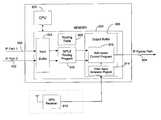
- the end-to-end network flowsact uncorrelated and independent causing the peak to average load ratio to decrease as the number of users on the network increases. In other words, the peak to average load ratio 100 of voice calls decreases as the number of voice calls increases, as expected from white noise statistics. This phenomenon is shown in FIG. 1 .
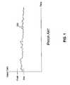
- FIG. 2illustrates an example of the fractal nature of a standard IP flow 200 over time.
- FIG. 2illustrates the standard IP flow 200 and an IP flow with CBR services added 250 .
- CBRConstant Bit Rate
- the peak to average load ratio of flow 250decreases from that of IP networks without CBR services. This is counterintuitive because there is less total bandwidth available for the other IP traffic sharing the transmission medium.
- the IP networkis basically a nonlinear, dynamic system with positive feedback.
- the addition of the CBR servicesreduces the feedback gain on the IP traffic flow, thereby reducing the peak traffic burstiness enough to increase the total IP packet flow.
- the addition of CBR servicesincreases total IP flow, bandwidth utilization is still inefficient and undesirably costly. Therefore, what is needed in the art is a way to further improve bandwidth efficiency and IP flow in a data communications network.
- a methodfor transmitting data between a first router and a second router within a network.
- the methodbegins by selecting a frequency for a dither signal that maximizes a flow rate of the network. The selected frequency is then used to switch between two sources of the data within the first router to transmit the data to the second router from the first router. Next, an arrival time that the data will arrive at the second router is determined and the second router is placed in an open state before the arrival time.
- routerssuch as a packet router, that may be used in accordance with an embodiment of the present invention.
- the methodmay also include selecting the frequency for a dither signal that maximizes the flow rate by varying a dither time as a function of the flow rate and determining the frequency that maximizes the flow rate as the selected frequency.
- the frequencymay be determined by finding the autocorrelation of the flow rate and determining the frequency that minimizes the autocorrelation as the selected frequency.
- arrival timemay be determined by determining a distance between the first router and the second router, determining a time required for the data to travel between the first router and the second router and determining an arrival time based on the time required.
- a methodfor transmitting data through a routing element of a network.
- the methodbegins by generating a periodic dither signal to regulate the transmission of data through the routing element.
- the periodic dither signalit then alternatively transmits from a first source of data and from a second source of data.
- the first source of data and the second source of datamay have different input paths to the routing element.
- the first source of data and the second source of datamay comprise different groups of data that exhibit a low correlation characteristic to each other.
- the first source of data and the second source of datacomprise different groups of data that are independent and uncorrelated to each other.
- an apparatusfor transmitting data within a network.
- the apparatusincludes a dither signal generator for generating a timing signal for alternating between a plurality of data sources at a frequency selected for maximizing a flow rate of data transmission and an admission control device for transmitting the data from the data sources in response to the timing signal.
- the timing signalmay be periodic.
- the admission control devicemay be capable of transmitting the data that further comprises a first packet from one of the data sources and a second, uncorrelated packet from another of the data sources, the second packet being transmitted over the same path as the first packet and being offset in time from the first packet.
- the apparatusmay also include a distance measuring device for determining a distance the data must travel and an arrival time of the packet based on the distance.
- the distance measuring devicemay be a location positioning receiver.
- a computer-readable mediumfor containing computer-executable instructions for transmitting data between routers within a network.
- the instructionsinclude generating a periodic dither signal to regulate the transmission of data through the routing element and alternatively transmitting from a first source of data and from a second source of data in response to the periodic dither signal.
- the first source of data and the second source of datamay have different input paths to the routing element.
- the first source of data and the second source of datamay comprise different groups of data that exhibit a low correlation characteristic to each other.
- the first source of data and the second source of datamay comprise different groups of data that are independent and uncorrelated to each other.
- FIG. 1is a graph of the peak to average load as a function of time in a prior art voice network
- FIG. 2is a graph of standard IP flow and IP flow with CBR services added as a function of time in a prior art network
- FIG. 3is a block diagram illustrating a network comprising routers A, B and C consistent with an exemplary embodiment of the present invention
- FIG. 4is a graph of the autocorrelation of voice traffic as a function of time in a prior art network
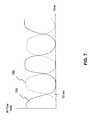
- FIG. 5is a graph of the autocorrelation of the IP flow as a function of time, which is consistent with an exemplary embodiment of the present invention
- FIG. 6is a graph of dither time as a function of time consistent with an exemplary embodiment of the present invention.
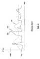
- FIG. 7is a graph of two uncorrelated IP flows being transmitted over a single medium consistent with an exemplary embodiment of the present invention.
- FIG. 8is a schematic diagram of a router consistent with an exemplary embodiment of the present invention.
- FIG. 9is a block diagram illustrating an exemplary embodiment of the present invention which is implemented in software within a conventional router.
- nonlinear dynamics of an optical fibermay be used to generate pulses.
- the article “CW Mode-Locked, 130 GHz Repetition Rate Soliton Laser Based on Modulational Instability” by P. Franco et al, published by Optical Amplifiers and Their Applications in June 1995discloses that a fiber exhibiting a modulation instability could be fed with a small probe signal that is AM or PM modulated. The instability of the fiber could use this small pertabation to generate soliton pulses.
- a router consistent with an embodiment of the present inventionis configured to utilize the nonlinear dynamics of an IP network and improve network flow.
- an embodiment of the present inventionimproves the admission control process on an IP router to feed the system with a periodic signal to force the IP flow into a deterministic, periodic, predictable pattern.
- the dither signalis a periodic timing signal produced at a frequency that maximizes IP flow. Because the flow is predictable, the router can determine the distance an IP packet (more generally referred to as data) will travel and the time it will arrive.
- the routeris desirably configured to be in an open state when the packet arrives at the predetermined time to quickly pass the IP packet through the router and onto the next path.
- the methodimproves the flow rate and decreases latency of the network.
- FIG. 1is a graph of the peak to average load as a function of time in a prior art voice network.
- FIG. 2graphically illustrates the standard IP flow and the IP flow with CBR services added in a prior art network.
- FIG. 3is a block diagram of an optical network comprising routers A, B and C.
- FIG. 4graphically illustrates the autocorrelation of voice traffic as a function of time.
- FIG. 5illustrates the autocorrelation of the IP flow as a function of time.
- FIG. 6graphically illustrates dither time as a function of time.
- FIG. 7graphically illustrates two uncorrelated IP flows being transmitted over a single medium consistent with an exemplary embodiment of the present invention.
- FIG. 8is a schematic diagram of a simplified portion of a router.
- FIG. 9is a block diagram illustrating an exemplary embodiment of the present invention implemented within software of a conventional router.
- FIG. 3illustrates an exemplary optical network comprising a router A 300 , router B 302 and router C 304 .
- a packet 306 sent from router A 300travels to router B 302 .
- router B 302it is desired that router B 302 be in the “open” position so that the packet 306 may be transmitted to router C 304 immediately.
- flow ratecan be increased, and latency may be reduced.
- a location positioning receivermay be attached to or incorporated within each router.
- a location positioning receivermay be attached to or incorporated within each router.
- Examples of such a receiverinclude conventional Global Positioning System (GPS) receivers, Long Range Navigation (LORAN) receivers, Satellite Navigation (SATNAV) receivers, or any other receiver that receives signals and calculates the arrival time and positional coordinates.
- GPSGlobal Positioning System
- LORANLong Range Navigation
- SATNAVSatellite Navigation
- the receiverprovides three-dimensional (3D) coordinates for the position of the router(or whatever device is routing data) and a fourth dimension of time. In this manner, the receiver functions as a global clock, providing synchronization for the system.
- 3D positional coordinatesprovided by each receiver attached to each router, the distance between the routers can be determined. Because the speed of the packets in the optical fiber is known, i.e.
- the time required for a packet 306 to travel from router A 300 to router B 302can be obtained.
- the anticipated arrival time a packet is to arrive at router Bmay be determined by adding the travel time (determined above), to the initial time (the time the packet 306 left router A 300 ), which is provided by the receiver connected to router A 300 .
- the arrival timemay be determined by assigning a “base” node and calculating the arrival time at the other network nodes.
- the arrival time at the other nodescan be calculated using the propagation speed of the signal through the fiber and the distance between the base nodes and the other nodes.
- the distance between the nodesi.e. the fiber length between the nodes, can be determined using any distance means, such as an Optical Time Domain Reflectometer (OTDR).
- OTDROptical Time Domain Reflectometer
- Admission Control Program of the routerdetermines when a packet is transmitted.
- Admission Control Programas described in this application may be implemented as a software module in readable memory or may be a hardwired or custom-designed device in hardware, despite the use of the “program” label.
- a dither signal produced by the Admission Control Programselects which data group is being transmitted.
- the data groupsare typically two IP flows entering the router or a single flow that is broken into two groups.
- the dither signal of the exemplary embodiment of the present inventionis optimized to provide a maximum IP flow rate.
- One way to determine the optimal dither rate (frequency)is to calculate the autocorrelation of the IP flow.
- autocorrelationis determined by shifting a function in time and multiplying it by itself. A value of 1 for the autocorrelation indicates that the function is completely positively correlated with itself. Likewise, a value of ⁇ 1 for the autocorrelation indicates that the function is negatively correlated with itself. A value of 0 signifies that the function is uncorrelated.
- FIG. 4shows the autocorrelation 400 of voice as a function of time.
- IP flowas described earlier, has correlation in the end-to-end flows.
- FIG. 5shows the autocorrelation 500 of the IP flow as a function of time. As shown in FIG. 5 , the autocorrelation 500 does not go to zero as a function of time. Instead, the autocorrelation 500 of the IP flow appears to be wavelike, varying between ⁇ 1.
- a preferred method for determining the optimal dither rateis to study the IP flow rate as a function of dither time.
- the results of varying dither rate as a function of time and measuring IP flow rateis shown in FIG. 6 .
- a maximum flow rate of IP flow 600occurs when dithering the transmission of data of a single IP flow between an open and closed transmission state. By selecting a dither time of 30 ms, the IP flow rate will be maximized.
- FIG. 7shows an example of transmitting a first flow 700 and a second independent, i.e. uncorrelated, flow 750 over a single medium.
- the uncorrelated flows 700 and 750are offset in time relative to each other, typically by approximately 180° according to the periodic dither signal.
- the first flow 700may be transmitted by a first router during a first time, in this case 0-50 ms. Transmission is then switched to the second flow 750 after the first flow falls off, i.e. after 50 ms.
- FIG. 8illustrates a simplified example of a router according to an embodiment of the present invention.
- the routermay have multiple IP traffic ingress paths, such as IP path 1 800 and IP path 2 802 , an IP traffic egress path 804 , a dither signal generator 806 and an admission control device 808 .
- the routermay be connected to or may contain a location positioning receiver, such as GPS receiver 810 .
- the splitting of IP flows into IP ingress path 800 and 802 respectivelymay be done by randomly splitting the flows into two groups, alternating packets from a buffer queue, or splitting the data into groups based on odd/even IP source or destination addresses.
- the GPS receiverprovides the location of the router in 3D coordinates and a global time.
- the dither signalstarts at an appropriate time based on the GPS signal and has a frequency that is selected to maximize the flow rate.
- IP path 1 800 and IP path 2 802are combined into one output path, IP egress path 804 , as discussed in reference to FIG. 7 .
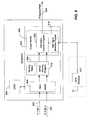
- FIG. 9illustrates an implementation of an embodiment of the present invention in software of a conventional router.
- a few examples of conventional routersinclude Versalar 25000, Optera Packet Core, Juniper M160 and Cisco GSR 12000.
- a conventional routermay include multiple ingress paths, such as IP path 1 800 and IP path 2 802 , a central processing unit (CPU) 900 , a memory 902 , and an IP egress path 804 .
- the routermay be connected to or may contain a location positioning receiver, such as GPS receiver 810 . While conventional routers typically include more components, those skilled in the art will appreciate that FIG. 9 has been simplified merely to avoid confusion.
- dataenters via IP path 1 801 or IP path 2 802 and enters the input buffer 904 .
- the CPU 900may process programs in the memory 902 , such as Multi Protocol Level Switching (MPLS) signaling program 910 , admission control program 912 and dither signal generation program 914 , to process and transmit the data in the input buffer 904 .
- MPLSMulti Protocol Level Switching
- the routerlearns where the data is to be routed.
- the routermay use a protocol such as Open Shortest Path First (OSPF).
- OSPFOpen Shortest Path First
- IP packetshave a field in their header that contains the address to which the packet is to be routed.
- routing tablessuch as routing table 908 , may be used at each router to look up the IP header and decide where to forward that packet.
- MPLS signaling program 910is used to simplify the routing process by encapsulating the IP packets with a short fixed-length label that acts as a shorthand representation of an IP packet's header.
- the dataencounters in the network, the contents of the header are analyzed and an appropriate label with which to encapsulate the packet is chosen.
- the MPLS labelis used to make the forwarding decision for the packet.
- MPLS signaling program 910also allows prioritization of services. For example, program 910 may allow voice to take high priority to ignore the dither signal because it is not exhibit fractal behavior. After determining where the data will be sent it is forwarded to an output buffer 906 .
- the output buffer 906includes an admission control program 912 and a dither signal generation program 914 to transmit the data over IP Egress Path 804 , as described previously.
- a dither signalmay be produced by the dither signal generation program 914 at a frequency which maximizes the EP flow rate.
- IP path 1 800 and IP path 2 802which are uncorrelated may be combined into a single IP egress path 804 by the admission control program 912 using the dither signal to regulate how fast and when the paths are alternately combined into the single output path.
- an exemplary embodiment of the present inventionincludes an admission control program of a router in a transmission system.
- a router consistent with an embodiment of the present inventionincreases IP flow and reduces latency by providing a dither signal at a frequency where the fractal spectrum of the traffic flow shows a peak to cause the IP flow to organize into a periodic and deterministic pattern.
- the frequency of the dither signalis optimized to maximize IP flow rate.
- Multiple, independent input pathscan be combined into a single output path using an admission control dither signal which regulates the frequency at which the paths are combined and when the paths are combined.
Landscapes
- Engineering & Computer Science (AREA)
- Computer Networks & Wireless Communication (AREA)
- Signal Processing (AREA)
- Data Exchanges In Wide-Area Networks (AREA)
Abstract
Description
Claims (28)
Priority Applications (1)
| Application Number | Priority Date | Filing Date | Title |
|---|---|---|---|
| US09/604,770US6865151B1 (en) | 2000-06-28 | 2000-06-28 | Methods and systems for optimizing data transmission in networks |
Applications Claiming Priority (1)
| Application Number | Priority Date | Filing Date | Title |
|---|---|---|---|
| US09/604,770US6865151B1 (en) | 2000-06-28 | 2000-06-28 | Methods and systems for optimizing data transmission in networks |
Publications (1)
| Publication Number | Publication Date |
|---|---|
| US6865151B1true US6865151B1 (en) | 2005-03-08 |
Family
ID=34216212
Family Applications (1)
| Application Number | Title | Priority Date | Filing Date |
|---|---|---|---|
| US09/604,770Expired - Fee RelatedUS6865151B1 (en) | 2000-06-28 | 2000-06-28 | Methods and systems for optimizing data transmission in networks |
Country Status (1)
| Country | Link |
|---|---|
| US (1) | US6865151B1 (en) |
Cited By (19)
| Publication number | Priority date | Publication date | Assignee | Title |
|---|---|---|---|---|
| US20030177233A1 (en)* | 2002-03-14 | 2003-09-18 | Yahoo! Inc. | Proxy client-server communication system |
| US20040174889A1 (en)* | 2000-07-25 | 2004-09-09 | Hisao Kikuchi | Network system and communication band control method thereof |
| US20060083168A1 (en)* | 2004-10-20 | 2006-04-20 | Rajat Prakash | Power-efficient data reception in a communication system with variable delay |
| US20060233170A1 (en)* | 2001-05-17 | 2006-10-19 | Dan Avida | Stream-Oriented Interconnect for Networked Computer Storage |
| US7161945B1 (en)* | 1999-08-30 | 2007-01-09 | Broadcom Corporation | Cable modem termination system |
| US20070118643A1 (en)* | 2005-11-18 | 2007-05-24 | Richard Mishra | Method and system for network planning |
| US20070147269A1 (en)* | 2005-12-22 | 2007-06-28 | Ettle David R | Method, system and apparatus for communications circuit design |
| US20070165532A1 (en)* | 2006-01-17 | 2007-07-19 | Cisco Technology, Inc. | Techniques for detecting loop-free paths that cross routing information boundaries |
| US20070198665A1 (en)* | 2006-02-20 | 2007-08-23 | Luca De Matteis | Method of configuring devices in a telecommunications network |
| US7296093B1 (en)* | 2001-12-31 | 2007-11-13 | Ciphermax, Inc. | Network processor interface system |
| US7325030B2 (en) | 2001-01-25 | 2008-01-29 | Yahoo, Inc. | High performance client-server communication system |
| US20080062947A1 (en)* | 2006-09-12 | 2008-03-13 | Alvaro Retana | Method and Apparatus for Passing Routing Information Among Mobile Routers |
| US20080130500A1 (en)* | 2006-11-30 | 2008-06-05 | Alvaro Retana | Automatic Overlapping Areas that Flood Routing Information |
| US20090086663A1 (en)* | 2007-09-27 | 2009-04-02 | Kah Kin Ho | Selecting Aggregation Nodes in a Network |
| US7561580B1 (en) | 2005-09-19 | 2009-07-14 | At&T Intellectual Property Ii, L.P. | Provisioning a multi-protocol label switching interface between networks |
| US20100008231A1 (en)* | 2006-08-29 | 2010-01-14 | Cisco Technology, Inc. | Method and Apparatus for Automatic Sub-Division of Areas that Flood Routing Information |
| US7729286B2 (en) | 2005-10-07 | 2010-06-01 | Amdocs Systems Limited | Method, system and apparatus for telecommunications service management |
| US20120281575A1 (en)* | 2009-11-18 | 2012-11-08 | Atsushi Iwata | Dynamic route branching system and dynamic route branching method |
| EP3175585A4 (en)* | 2014-07-30 | 2018-04-11 | Optulink Inc. | Voice optimization enablement apparatus |
Citations (5)
| Publication number | Priority date | Publication date | Assignee | Title |
|---|---|---|---|---|
| US3889065A (en)* | 1974-07-01 | 1975-06-10 | Us Navy | Acoustic devices for time-multiplexed communication |
| US4649536A (en)* | 1985-09-23 | 1987-03-10 | Motorola, Inc. | Flexible multiplex system for time division multiplex |
| US5291486A (en)* | 1991-08-19 | 1994-03-01 | Sony Corporation | Data multiplexing apparatus and multiplexed data demultiplexing apparatus |
| US5453981A (en)* | 1990-10-16 | 1995-09-26 | Kabushiki Kaisha Toshiba | Method of controlling communication network incorporating virtual channels exchange nodes and virtual paths exchange nodes |
| US5663962A (en)* | 1994-09-29 | 1997-09-02 | Cselt- Centro Studi E Laboratori Telecomunicazioni S.P.A. | Method of multiplexing streams of audio-visual signals coded according to standard MPEG1 |
- 2000
- 2000-06-28USUS09/604,770patent/US6865151B1/ennot_activeExpired - Fee Related
Patent Citations (5)
| Publication number | Priority date | Publication date | Assignee | Title |
|---|---|---|---|---|
| US3889065A (en)* | 1974-07-01 | 1975-06-10 | Us Navy | Acoustic devices for time-multiplexed communication |
| US4649536A (en)* | 1985-09-23 | 1987-03-10 | Motorola, Inc. | Flexible multiplex system for time division multiplex |
| US5453981A (en)* | 1990-10-16 | 1995-09-26 | Kabushiki Kaisha Toshiba | Method of controlling communication network incorporating virtual channels exchange nodes and virtual paths exchange nodes |
| US5291486A (en)* | 1991-08-19 | 1994-03-01 | Sony Corporation | Data multiplexing apparatus and multiplexed data demultiplexing apparatus |
| US5663962A (en)* | 1994-09-29 | 1997-09-02 | Cselt- Centro Studi E Laboratori Telecomunicazioni S.P.A. | Method of multiplexing streams of audio-visual signals coded according to standard MPEG1 |
Non-Patent Citations (2)
| Title |
|---|
| "CW Mode-Locked, 130 GHz Repetition Rate Soliton Laser Based on Modulational Instability" by P. Franco, F. Fontana, I Cristiani, M. Midrio and M. Romagnoli, in Optical Amplifiers and their Application, Jun. 15-17, 1995, vol. 8, pp 271-273. |
| "High-Speed Networks: TCP/IP and ATM Design Principles" By William Stallings, Chapter 8, pp. 181-207. |
Cited By (34)
| Publication number | Priority date | Publication date | Assignee | Title |
|---|---|---|---|---|
| US7161945B1 (en)* | 1999-08-30 | 2007-01-09 | Broadcom Corporation | Cable modem termination system |
| US20040174889A1 (en)* | 2000-07-25 | 2004-09-09 | Hisao Kikuchi | Network system and communication band control method thereof |
| US6975648B2 (en)* | 2000-07-25 | 2005-12-13 | Hitachi, Ltd. | Network system and communication band control method thereof |
| US7325030B2 (en) | 2001-01-25 | 2008-01-29 | Yahoo, Inc. | High performance client-server communication system |
| US7944936B2 (en)* | 2001-05-17 | 2011-05-17 | Netapp, Inc. | Stream-oriented interconnect for networked computer storage |
| US20060233170A1 (en)* | 2001-05-17 | 2006-10-19 | Dan Avida | Stream-Oriented Interconnect for Networked Computer Storage |
| US7296093B1 (en)* | 2001-12-31 | 2007-11-13 | Ciphermax, Inc. | Network processor interface system |
| US7103671B2 (en)* | 2002-03-14 | 2006-09-05 | Yahoo! Inc. | Proxy client-server communication system |
| US20030177233A1 (en)* | 2002-03-14 | 2003-09-18 | Yahoo! Inc. | Proxy client-server communication system |
| US20060083168A1 (en)* | 2004-10-20 | 2006-04-20 | Rajat Prakash | Power-efficient data reception in a communication system with variable delay |
| US7898954B2 (en)* | 2004-10-20 | 2011-03-01 | Qualcomm Incorporated | Power-efficient data reception in a communication system with variable delay |
| US7561580B1 (en) | 2005-09-19 | 2009-07-14 | At&T Intellectual Property Ii, L.P. | Provisioning a multi-protocol label switching interface between networks |
| US7729286B2 (en) | 2005-10-07 | 2010-06-01 | Amdocs Systems Limited | Method, system and apparatus for telecommunications service management |
| US8082335B2 (en) | 2005-11-18 | 2011-12-20 | Amdocs Systems Limited | Method and system for telecommunications network planning and management |
| US20070118643A1 (en)* | 2005-11-18 | 2007-05-24 | Richard Mishra | Method and system for network planning |
| US20070147269A1 (en)* | 2005-12-22 | 2007-06-28 | Ettle David R | Method, system and apparatus for communications circuit design |
| US7797425B2 (en) | 2005-12-22 | 2010-09-14 | Amdocs Systems Limited | Method, system and apparatus for communications circuit design |
| US7889655B2 (en) | 2006-01-17 | 2011-02-15 | Cisco Technology, Inc. | Techniques for detecting loop-free paths that cross routing information boundaries |
| US20070165532A1 (en)* | 2006-01-17 | 2007-07-19 | Cisco Technology, Inc. | Techniques for detecting loop-free paths that cross routing information boundaries |
| US8380833B2 (en) | 2006-02-20 | 2013-02-19 | Amdocs Systems Limited | Method of configuring devices in a telecommunications network |
| US20070198665A1 (en)* | 2006-02-20 | 2007-08-23 | Luca De Matteis | Method of configuring devices in a telecommunications network |
| US20100008231A1 (en)* | 2006-08-29 | 2010-01-14 | Cisco Technology, Inc. | Method and Apparatus for Automatic Sub-Division of Areas that Flood Routing Information |
| US8699410B2 (en) | 2006-08-29 | 2014-04-15 | Cisco Technology, Inc. | Method and apparatus for automatic sub-division of areas that flood routing information |
| US7899005B2 (en) | 2006-09-12 | 2011-03-01 | Cisco Technology, Inc. | Method and apparatus for passing routing information among mobile routers |
| US20080062947A1 (en)* | 2006-09-12 | 2008-03-13 | Alvaro Retana | Method and Apparatus for Passing Routing Information Among Mobile Routers |
| WO2008067041A1 (en)* | 2006-11-30 | 2008-06-05 | Cisco Technology, Inc. | Automatic overlapping domains that flood routing information |
| US20080130500A1 (en)* | 2006-11-30 | 2008-06-05 | Alvaro Retana | Automatic Overlapping Areas that Flood Routing Information |
| US8009591B2 (en)* | 2006-11-30 | 2011-08-30 | Cisco Technology, Inc. | Automatic overlapping areas that flood routing information |
| US20090086663A1 (en)* | 2007-09-27 | 2009-04-02 | Kah Kin Ho | Selecting Aggregation Nodes in a Network |
| US7936732B2 (en) | 2007-09-27 | 2011-05-03 | Cisco Technology, Inc. | Selecting aggregation nodes in a network |
| US20120281575A1 (en)* | 2009-11-18 | 2012-11-08 | Atsushi Iwata | Dynamic route branching system and dynamic route branching method |
| US9001656B2 (en)* | 2009-11-18 | 2015-04-07 | Nec Corporation | Dynamic route branching system and dynamic route branching method |
| US9385937B2 (en) | 2009-11-18 | 2016-07-05 | Nec Corporation | Dynamic route branching system and dynamic route branching method |
| EP3175585A4 (en)* | 2014-07-30 | 2018-04-11 | Optulink Inc. | Voice optimization enablement apparatus |
Similar Documents
| Publication | Publication Date | Title |
|---|---|---|
| US6865151B1 (en) | Methods and systems for optimizing data transmission in networks | |
| Potti et al. | A packet priority approach to mitigate starvation in wireless mesh network with multimedia traffic | |
| KR100779768B1 (en) | Dynamic and traffic-driven optimization of message routing to geographical addresses | |
| US6898205B1 (en) | Robust transport of IP traffic over wdm using optical burst switching | |
| US7822023B2 (en) | Routing data packets through a wireless network | |
| Zang et al. | Connection management for wavelength-routed WDM networks | |
| US8705381B2 (en) | Communication embodiments and low latency path selection in a multi-topology network | |
| RU2011116332A (en) | METHOD AND DEVICES FOR MANAGING OVERLOAD | |
| WO2002067497A3 (en) | Method and system for packet communication employing path diversity | |
| Pham et al. | Multi-path routing protocol with load balancing policy in mobile ad hoc network | |
| Yoo et al. | Comparative study of contention resolution policies in optical burst-switched WDM networks | |
| Yi et al. | A load aware routing (LWR) based on local information | |
| Sharma et al. | Improving the QOS in MANET by Enhancing the Routing Technique of AOMDV Protocol | |
| JP3422952B2 (en) | Packet switched network section free band measurement method and apparatus | |
| Rajendiran et al. | Route efficient on demand multicast routing protocol with stability link for MANETs | |
| Kunavut et al. | Generalized Multi-Constrained Path (G_MCP) QoS Routing Algorithm for Mobile Ad hoc Networks. | |
| Ktari et al. | Load balanced multipath routing in mobile ad hoc network | |
| Roberts et al. | WSN performance parameters of AODV, DYMO, OLSR and IERP in RWP mobility model through QualNet | |
| Cao et al. | Background Traffic‐Based Retransmission Algorithm for Multimedia Streaming Transfer over Concurrent Multipaths | |
| Frikha et al. | Implementation and simulation of OLSR protocol with QoS in Ad Hoc Networks | |
| Arora et al. | Toward the use of local monitoring and network-wide correction to achieve QoS guarantees in mobile ad hoc networks | |
| Calafate et al. | A flexible and tunable route discovery mechanism for on-demand protocols | |
| Cerveira et al. | A time-based admission control mechanism for IEEE 802.11 ad hoc networks | |
| Ping et al. | Multi-constraint quality of service routing algorithm for dynamic topology networks | |
| Newton et al. | An Efficient Hybrid Path Selection Algorithm for an Integrated Network Environment |
Legal Events
| Date | Code | Title | Description |
|---|---|---|---|
| AS | Assignment | Owner name:NORTEL NETWORKS CORPORATION, CANADA Free format text:ASSIGNMENT OF ASSIGNORS INTEREST;ASSIGNOR:SAUNDERS, ROSS ALEXANDER;REEL/FRAME:010902/0855 Effective date:20000622 | |
| FEPP | Fee payment procedure | Free format text:PAYER NUMBER DE-ASSIGNED (ORIGINAL EVENT CODE: RMPN); ENTITY STATUS OF PATENT OWNER: LARGE ENTITY Free format text:PAYOR NUMBER ASSIGNED (ORIGINAL EVENT CODE: ASPN); ENTITY STATUS OF PATENT OWNER: LARGE ENTITY | |
| AS | Assignment | Owner name:NORTEL NETWORKS LIMITED, CANADA Free format text:CHANGE OF NAME;ASSIGNOR:NORTEL NETWORKS CORPORATION;REEL/FRAME:016234/0088 Effective date:20010405 | |
| CC | Certificate of correction | ||
| FPAY | Fee payment | Year of fee payment:4 | |
| AS | Assignment | Owner name:ROCKSTAR BIDCO, LP, NEW YORK Free format text:ASSIGNMENT OF ASSIGNORS INTEREST;ASSIGNOR:NORTEL NETWORKS LIMITED;REEL/FRAME:027164/0356 Effective date:20110729 | |
| FPAY | Fee payment | Year of fee payment:8 | |
| AS | Assignment | Owner name:ROCKSTAR CONSORTIUM US LP, TEXAS Free format text:ASSIGNMENT OF ASSIGNORS INTEREST;ASSIGNOR:ROCKSTAR BIDCO, LP;REEL/FRAME:034086/0173 Effective date:20120509 | |
| AS | Assignment | Owner name:RPX CLEARINGHOUSE LLC, CALIFORNIA Free format text:ASSIGNMENT OF ASSIGNORS INTEREST;ASSIGNORS:ROCKSTAR CONSORTIUM US LP;ROCKSTAR CONSORTIUM LLC;BOCKSTAR TECHNOLOGIES LLC;AND OTHERS;REEL/FRAME:034924/0779 Effective date:20150128 | |
| AS | Assignment | Owner name:JPMORGAN CHASE BANK, N.A., AS COLLATERAL AGENT, IL Free format text:SECURITY AGREEMENT;ASSIGNORS:RPX CORPORATION;RPX CLEARINGHOUSE LLC;REEL/FRAME:038041/0001 Effective date:20160226 | |
| REMI | Maintenance fee reminder mailed | ||
| LAPS | Lapse for failure to pay maintenance fees | ||
| STCH | Information on status: patent discontinuation | Free format text:PATENT EXPIRED DUE TO NONPAYMENT OF MAINTENANCE FEES UNDER 37 CFR 1.362 | |
| FP | Lapsed due to failure to pay maintenance fee | Effective date:20170308 | |
| AS | Assignment | Owner name:RPX CLEARINGHOUSE LLC, CALIFORNIA Free format text:RELEASE (REEL 038041 / FRAME 0001);ASSIGNOR:JPMORGAN CHASE BANK, N.A.;REEL/FRAME:044970/0030 Effective date:20171222 Owner name:RPX CORPORATION, CALIFORNIA Free format text:RELEASE (REEL 038041 / FRAME 0001);ASSIGNOR:JPMORGAN CHASE BANK, N.A.;REEL/FRAME:044970/0030 Effective date:20171222 |