US6863676B2 - Excisional biopsy devices and methods - Google Patents
Excisional biopsy devices and methodsDownload PDFInfo
- Publication number
- US6863676B2 US6863676B2US10/066,353US6635302AUS6863676B2US 6863676 B2US6863676 B2US 6863676B2US 6635302 AUS6635302 AUS 6635302AUS 6863676 B2US6863676 B2US 6863676B2
- Authority
- US
- United States
- Prior art keywords
- tissue
- cutting tool
- tissue collection
- tubular member
- probe
- Prior art date
- Legal status (The legal status is an assumption and is not a legal conclusion. Google has not performed a legal analysis and makes no representation as to the accuracy of the status listed.)
- Expired - Fee Related, expires
Links
Images


Classifications
- A—HUMAN NECESSITIES
- A61—MEDICAL OR VETERINARY SCIENCE; HYGIENE
- A61B—DIAGNOSIS; SURGERY; IDENTIFICATION
- A61B10/00—Instruments for taking body samples for diagnostic purposes; Other methods or instruments for diagnosis, e.g. for vaccination diagnosis, sex determination or ovulation-period determination; Throat striking implements
- A61B10/02—Instruments for taking cell samples or for biopsy
- A61B10/0233—Pointed or sharp biopsy instruments
- A61B10/0266—Pointed or sharp biopsy instruments means for severing sample
- A—HUMAN NECESSITIES
- A61—MEDICAL OR VETERINARY SCIENCE; HYGIENE
- A61B—DIAGNOSIS; SURGERY; IDENTIFICATION
- A61B10/00—Instruments for taking body samples for diagnostic purposes; Other methods or instruments for diagnosis, e.g. for vaccination diagnosis, sex determination or ovulation-period determination; Throat striking implements
- A61B10/02—Instruments for taking cell samples or for biopsy
- A61B10/04—Endoscopic instruments, e.g. catheter-type instruments
- A—HUMAN NECESSITIES
- A61—MEDICAL OR VETERINARY SCIENCE; HYGIENE
- A61B—DIAGNOSIS; SURGERY; IDENTIFICATION
- A61B17/00—Surgical instruments, devices or methods
- A61B17/32—Surgical cutting instruments
- A61B17/3205—Excision instruments
- A61B17/3207—Atherectomy devices working by cutting or abrading; Similar devices specially adapted for non-vascular obstructions
- A61B17/320725—Atherectomy devices working by cutting or abrading; Similar devices specially adapted for non-vascular obstructions with radially expandable cutting or abrading elements
- A—HUMAN NECESSITIES
- A61—MEDICAL OR VETERINARY SCIENCE; HYGIENE
- A61B—DIAGNOSIS; SURGERY; IDENTIFICATION
- A61B18/00—Surgical instruments, devices or methods for transferring non-mechanical forms of energy to or from the body
- A61B18/04—Surgical instruments, devices or methods for transferring non-mechanical forms of energy to or from the body by heating
- A61B18/12—Surgical instruments, devices or methods for transferring non-mechanical forms of energy to or from the body by heating by passing a current through the tissue to be heated, e.g. high-frequency current
- A61B18/14—Probes or electrodes therefor
- A61B18/1482—Probes or electrodes therefor having a long rigid shaft for accessing the inner body transcutaneously in minimal invasive surgery, e.g. laparoscopy
- A—HUMAN NECESSITIES
- A61—MEDICAL OR VETERINARY SCIENCE; HYGIENE
- A61B—DIAGNOSIS; SURGERY; IDENTIFICATION
- A61B10/00—Instruments for taking body samples for diagnostic purposes; Other methods or instruments for diagnosis, e.g. for vaccination diagnosis, sex determination or ovulation-period determination; Throat striking implements
- A61B10/0041—Detection of breast cancer
- A—HUMAN NECESSITIES
- A61—MEDICAL OR VETERINARY SCIENCE; HYGIENE
- A61B—DIAGNOSIS; SURGERY; IDENTIFICATION
- A61B10/00—Instruments for taking body samples for diagnostic purposes; Other methods or instruments for diagnosis, e.g. for vaccination diagnosis, sex determination or ovulation-period determination; Throat striking implements
- A61B10/02—Instruments for taking cell samples or for biopsy
- A—HUMAN NECESSITIES
- A61—MEDICAL OR VETERINARY SCIENCE; HYGIENE
- A61B—DIAGNOSIS; SURGERY; IDENTIFICATION
- A61B18/00—Surgical instruments, devices or methods for transferring non-mechanical forms of energy to or from the body
- A61B2018/00005—Cooling or heating of the probe or tissue immediately surrounding the probe
- A61B2018/00011—Cooling or heating of the probe or tissue immediately surrounding the probe with fluids
- A—HUMAN NECESSITIES
- A61—MEDICAL OR VETERINARY SCIENCE; HYGIENE
- A61B—DIAGNOSIS; SURGERY; IDENTIFICATION
- A61B18/00—Surgical instruments, devices or methods for transferring non-mechanical forms of energy to or from the body
- A61B2018/00315—Surgical instruments, devices or methods for transferring non-mechanical forms of energy to or from the body for treatment of particular body parts
- A61B2018/00333—Breast
- A—HUMAN NECESSITIES
- A61—MEDICAL OR VETERINARY SCIENCE; HYGIENE
- A61B—DIAGNOSIS; SURGERY; IDENTIFICATION
- A61B18/00—Surgical instruments, devices or methods for transferring non-mechanical forms of energy to or from the body
- A61B18/04—Surgical instruments, devices or methods for transferring non-mechanical forms of energy to or from the body by heating
- A61B18/12—Surgical instruments, devices or methods for transferring non-mechanical forms of energy to or from the body by heating by passing a current through the tissue to be heated, e.g. high-frequency current
- A61B18/14—Probes or electrodes therefor
- A61B2018/1405—Electrodes having a specific shape
- A61B2018/1407—Loop
- A—HUMAN NECESSITIES
- A61—MEDICAL OR VETERINARY SCIENCE; HYGIENE
- A61B—DIAGNOSIS; SURGERY; IDENTIFICATION
- A61B18/00—Surgical instruments, devices or methods for transferring non-mechanical forms of energy to or from the body
- A61B18/04—Surgical instruments, devices or methods for transferring non-mechanical forms of energy to or from the body by heating
- A61B18/12—Surgical instruments, devices or methods for transferring non-mechanical forms of energy to or from the body by heating by passing a current through the tissue to be heated, e.g. high-frequency current
- A61B18/14—Probes or electrodes therefor
- A61B2018/1475—Electrodes retractable in or deployable from a housing
- A—HUMAN NECESSITIES
- A61—MEDICAL OR VETERINARY SCIENCE; HYGIENE
- A61B—DIAGNOSIS; SURGERY; IDENTIFICATION
- A61B90/00—Instruments, implements or accessories specially adapted for surgery or diagnosis and not covered by any of the groups A61B1/00 - A61B50/00, e.g. for luxation treatment or for protecting wound edges
- A61B90/36—Image-producing devices or illumination devices not otherwise provided for
- A61B90/37—Surgical systems with images on a monitor during operation
- A61B2090/378—Surgical systems with images on a monitor during operation using ultrasound
- A61B2090/3782—Surgical systems with images on a monitor during operation using ultrasound transmitter or receiver in catheter or minimal invasive instrument
- A61B2090/3784—Surgical systems with images on a monitor during operation using ultrasound transmitter or receiver in catheter or minimal invasive instrument both receiver and transmitter being in the instrument or receiver being also transmitter
- A—HUMAN NECESSITIES
- A61—MEDICAL OR VETERINARY SCIENCE; HYGIENE
- A61B—DIAGNOSIS; SURGERY; IDENTIFICATION
- A61B2218/00—Details of surgical instruments, devices or methods for transferring non-mechanical forms of energy to or from the body
- A61B2218/001—Details of surgical instruments, devices or methods for transferring non-mechanical forms of energy to or from the body having means for irrigation and/or aspiration of substances to and/or from the surgical site
- A61B2218/002—Irrigation
Definitions
- the present inventionpertains to the field of soft tissue excisional biopsy devices and methods.
- the present inventionrelates to the field of devices and methods for excising suspicious lesions from soft tissue, such as breast tissue.
- Breast canceris a major threat and concern to women. Early detection and treatment of suspicious or cancerous lesions in the breast has been shown to improve long-term survival of the patient. The trend is, therefore, to encourage women not only to perform monthly self-breast examination and obtain a yearly breast examination by a qualified physician, but also to undergo annual screening mammography commencing at age 40. Mammography is the only screening modality available today that can detect small, nonpalpable lesions. These nonpalpable lesions may appear as opaque densities relative to normal breast parenchyma and fat or as clusters of microcalcifications.
- the conventional method for diagnosing, localizing and excising nonpalpable lesions detected by mammographygenerally involves a time-consuming, multi-step process.
- the patientgoes to the radiology department where the radiologist finds and localizes the lesion either using mammography or ultrasound guidance.
- a radio-opaque wireis inserted into the breast.
- the distal end of the wiremay include a small hook or loop. Ideally, this is placed adjacent to the suspicious area to be biopsied.
- the patientis then transported to the operating room. Under general or local anesthesia, the surgeon performs a procedure called a needle-localized breast biopsy.
- the surgeonguided by the wire previously placed in the patient's breast, excises a mass of tissue around the distal end of the wire.
- the specimenis sent to the radiology department where a specimen radiograph is taken to confirm that the suspicious lesion is contained within the excised specimen.
- the surgeon, patient, anesthesiologist and operating room staffwait in the operating room for confirmation of that fact from the radiologist before the operation is completed.
- the suspicious lesionshould ideally be excised in toto with a small margin or rim of normal breast tissue on all sides. Obtaining good margins of normal tissue is extremely dependent upon the skill and experience of the surgeon, and often an excessively large amount of normal breast tissue is removed to ensure that the lesion is located within the specimen. This increases the risk of post-operative complications, including bleeding and permanent breast deformity. As 80% of breast biopsies today are benign, many women unnecessarily suffer from permanent scarring and deformity from such benign breast biopsies.
- Another conventional techniquelocalizes the suspicious lesion using stereotactic digital mammography.
- the patientis placed prone on a special table that includes a hole to allow the designated breast to dangle therethrough.
- the breastis compressed between two mammography plates, which stabilizes the breast to be biopsied and allows the digital mammograms to be taken. At least two images are taken 30 degrees apart to obtain stereotactic views.
- the x, y and z coordinates targeting the lesionare calculated by a computer.
- the physicianthen aligns a special mechanical stage mounted under the table that places the biopsy device into the breast to obtain the sample or samples.
- Fine needle aspirationuses a small gauge needle, usually 20 to 25 gauge, to aspirate a small sample of cells from the lesion or suspicious area.
- the sampleis smeared onto slides that are stained and examined by a cytopathologist.
- individual cells in the smearsare examined, and tissue architecture or histology is generally not preserved.
- Fine needle aspirationis also very dependent upon the skill and experience of the operator and can result in a high non-diagnostic rate (up to about 83%), due to inadequate sample collection or preparation.
- Core needle biopsyuses a larger size needle, usually 14 gauge to sample the lesion. Tissue architecture and histology are preserved with this method.
- a side-cutting deviceconsisting of an inner trough with an outer cutting cannula is attached to a spring-loaded device for a rapid semi-automated firing action. After the lesion is localized, local anaesthetic is instilled and a small incision is made in the skin with a scalpel. The device enters the breast and the needle tip is guided into the breast up to the targeted lesion. The device is fired. First, the inner cannula containing the trough rapidly penetrates the lesion.
- the outer cutting cannularapidly advances over the inner cannula cutting a sample of tissue off in the trough. The whole device is then removed and the sample retrieved. Multiple penetrations of the core needle through the breast and into the lesion are required to obtain an adequate sampling of the lesion. Over 10 samples have been recommended by some.
- the vacuum-assisted breast biopsy systemis a larger semi-automated side-cutting device. It is usually 11 gauge in diameter and is more sophisticated than the core needle biopsy device. Multiple large samples can be obtained from the lesion without having to reinsert the needle each time. A vacuum is added to suck the tissue into the trough. The rapid firing action of the spring-loaded core needle device is replaced with an oscillating outer cannula that cuts the breast tissue off in the trough. The physician controls the speed at which the outer cannula advances over the trough and can rotate the alignment of the trough in a clockwise fashion to obtain multiple samples.
- a fine needle aspirate, needle core biopsy or vacuum-assisted biopsyshows malignancy or a specific benign diagnosis of atypical hyperplasia
- the patientneeds to undergo another procedure, the traditional needle-localized breast biopsy, to fully excise the area with an adequate margin of normal breast tissue.
- the vacuum-assisted deviceremoves the whole targeted lesion. If this occurs, a small titanium clip should be placed in the biopsy field. This clip marks the area if a needle-localized breast biopsy is subsequently required for the previously mentioned reasons.
- Another method of biopsying the suspicious lesionutilizes a large end-cutting core device measuring 0.5 cm to 2.0 cm in diameter. This also uses the stereotactic table for stabilization and localization. After the lesion coordinates are calculated and local anesthesia instilled, an incision large enough is permit entry of the bore is made at the entry site with a scalpel. The breast tissue is cored down to and past the lesion. Once the specimen is retrieved, the patient is turned onto her back and the surgeon cauterizes bleeding vessels under direct vision. The incision, measuring 0.5 to larger than 2.0 cm is sutured closed.
- the stereotactic tablerequires awkward positioning of the patient and may be extremely uncomfortable. The woman must lie prone during the entire procedure, which may be impossible for some patients.
- the lesion to be biopsiedmust be in the center working area of the mammography plates. This may be extremely difficult and uncomfortable for the patient if the lesion is very posterior near the chest wall or high towards the axilla.
- the womanis subjected to increased radiation exposure as multiple radiographs are required throughout the course of the procedure to: (1) confirm that the lesion is within the working area of the mammography plates, (2) obtain the stereotactic coordinates (at least two views), (3) verify the positioning of the biopsy needle prior to obtaining tissue, and (4) verify that the lesion was indeed sampled. If any difficulty is encountered during the procedure, additional radiographic exposures are required to verify correction of the problem.
- the core needle biopsy and vacuum-assisted devicesboth cut into the tumor and carve out multiple samples for examination. While cutting into the tumor, cancerous cells may be dislodged. Cutting across blood vessels at the same time may allow the freed cancerous cells access to the blood stream, thus possibly seeding the tumor beyond its original locus.
- the long-term consequences of tumor seeding with the risk of bloodborne metastasesare unknown at this time, as the techniques are relatively new.
- metastases growing in needle tracks from previous biopsies of a cancerous massMost of these are from lung or liver cancers.
- the large core cutting device(0.5 cm to 2.0 cm) generally eliminates the risk of needle track seeding as it is designed to excise the lesion intact.
- a stereotactic tableis required with the same inherent awkwardness for the patient, as discussed above. Bleeding is controlled, albeit manually, requiring that the patient wait until the end of the procedure to be turned over. Compression is used to stabilize the breast and localize the lesions.
- the breastmay be torqued and distorted between the compression plates such that when the plates are removed after the biopsy, the large core track left behind may not be straight, but actually tortuous. This can result in permanent breast deformity.
- the location of the insertion site into the breastis dictated by the positioning of the breast in the machine and not by the physician.
- the entry siteis usually away from the nipple-areolar complex and is usually located on the more exposed areas of the breast.
- the incisionis usually very small and the scar almost unappreciable.
- the large core biopsy device0.5 to 2.0 cm
- a large incisionis needed. Such a large incision often results in a non-aesthetically placed scar.
- the newer conventional minimally invasive breast biopsy deviceshave improved in some ways the ability to diagnose mammographically detected nonpalpable lesions. These devices give the patient a choice as to how she wants the diagnosis to be made. Moreover, these devices are substantially less expensive than the older traditional needle-localized breast biopsy. They are not, however, the final solution. Due to the above-discussed problems and risks associated with compression, needle-track seeding, blood borne metastases, bleeding, radiation exposure and awkwardness of the stereotactic table, more refined devices and methods are needed to resolve these issues. Also, the conventional biopsy devices do not consider margins in their excisions and if cancer is diagnosed, the patient must undergo a needle-localized breast lumpectomy to ensure that adequate margins are removed around the cancer. Devices and methods, therefore, must address the problem of obtaining adequate margins so that a second procedure is not required. Margins, moreover, cannot be assessed while the breast is being compressed.
- an object of the present inventionto provide devices and methods to efficiently and safely excise suspicious lesions from the breast. It is also an object of the present invention to provide devices and methods that remove the entire lesion intact with the minimum amount of normal tissue surrounding the lesion needed to provide adequate margins. It is a further object of the present invention to provide devices and methods that provide hemostasis in the breast to minimize complications of ecchymosis, hematoma formation, and breast edema. It is another object of the present invention to provide methods and devices to provide intra-tissue ultrasonic guidance to provide real time, in situ monitoring of the procedure. A still further object is to provide devices and methods that allow the physician to minimize the size of the incision through which the procedure is performed and to leave an aesthetically acceptable scar on the breast.
- an embodiment of an excisional biopsy systemcomprises a tubular member including a proximal end and a distal end, the tubular member defining a first window near the distal end, and a first removable probe that includes a proximal portion including cutting tool extending means, a distal portion and a cutting tool near the distal portion, the first removable probe being configured to fit at least partially within the tubular member to enable the cutting tool to selectively bow out of and to retract within the first window when the cutting tool extending means are activated.
- the first removable probemay further include a window slide and the proximal end may further include a window slide extending means, the window slide being configured to selectively cover a portion of the first window when the window slide extending means are activated.
- the cutting toolmay include one of a thin ribbon sharpened on a leading edge thereof and a wire.
- the cutting toolmay include an RF cutting tool and the first removable probe may be adapted to be connected to an RF power source.
- the cutting toolmay include a monopolar or a bipolar RF cutting tool.
- the tubular membermay include a first internal guide that is configured to enable the first removable probe to slide within the tubular member.
- the first removable probemay include a second internal guide, the second internal guide enabling the cutting tool to slide within the first removable probe when the cutting tool extending means are activated.
- the first removable probemay include a third internal guide, the third internal guide enabling the window slide to slide within the first removable probe when the window slide extending means are activated.
- the biopsy systemmay further include a second removable probe comprising a proximal section including a tissue collection device extending means and a distal section including a tissue collection device, the second removable probe being configured to fit at least partially within the tubular member to enable the tissue collection device to extend out of and to retract within the first window when the tissue collection device extending means are activated.
- the tubular membermay define a second window near the distal end thereof, and the biopsy system may further include a second removable probe comprising a proximal section including a tissue collection device extending means and a distal section including a tissue collection device, the second removable probe being configured to fit at least partially within the tubular member to enable the tissue collection device to selectively extend out of and to retract within the second window when the tissue collection device extending means are activated.
- a second removable probecomprising a proximal section including a tissue collection device extending means and a distal section including a tissue collection device, the second removable probe being configured to fit at least partially within the tubular member to enable the tissue collection device to selectively extend out of and to retract within the second window when the tissue collection device extending means are activated.
- the tissue collection devicemay include a thin ribbon or a wire, as well as a thin flexible sheet of material attached to the thin ribbon or wire, the thin flexible sheet at least partially encapsulating a tissue specimen as the thin ribbon or wire is extended and the tubular member rotated.
- the thin flexible sheet of materialmay include a bag attached to the ribbon or wire so as to open and close when the ribbon or wire is extended and retracted, respectively.
- the tissue collection devicemay include a thin ribbon or a wire, and a thin flexible sheet of material may be attached to the thin ribbon or wire, the thin flexible sheet at least partially encapsulating a tissue specimen as the thin ribbon or wire is extended and the tubular member rotated.
- the thin flexible sheet of materialmay include a bag attached to the thin ribbon or wire so as to open and close when the thin ribbon or wire is extended and retracted, respectively.
- the tubular membermay include a first internal guide that is configured to enable one of the first and the second removable probe to slide within the tubular member until the cutting tool and/or the tissue collection device faces out of the first window.
- the tubular membermay include a second internal guide that is configured to enable the second removable probe to slide within the tubular member until the tissue collection device faces out of the second window.
- the distal portion of the first removable probemay further include a tissue collection device near a trailing edge of the cutting tool, the tissue collection device being configured to selectively extend out of and retract into the first window.
- the proximal portion of the first removable probemay include a tissue collection device extending means, the tissue collection device extending means being adapted to enable the tissue collection device to extend out of and to retract within the first window independently of the cutting tool.
- the tissue collection devicemay be coupled to the cutting tool and the cutting tool extending means may also be configured to selectively extend the tissue collection device out of the first window and retract the tissue collection device into the first window as the cutting tool is extended and retracted, respectively.
- the first removable probemay include an insulator between the tissue collection device and the cutting tool.
- the insulatormay include an air gap and/or an insulating material attached to and separating the cutting tool from the tissue collection device.
- the first removable probemay define one or more internal lumens that terminate near the distal portion as an opening formed in a surface of the first removable probe, the opening being adapted to deliver a pharmaceutical agent and/or to provide suction.
- a third removable probemay be provided, the third removable probe being configured to fit at least partially within the tubular member and including an imaging device mounted therein.
- the imaging devicemay include an ultrasound sensor, such as a linear array of ultrasound transducers, for example.
- the ultrasound sensormay be disposed near a distal tip of the third removable probe and away from the cutting tool, so that the ultrasound sensor sweeps a plane ahead of the cutting tool as the tubular member rotates.
- the ultrasound sensormay be tuned within the range from about 7.5 MHz to about 20 MHz.
- the ultrasound sensormay be disposed within the tubular member at an angle ⁇ relative to the cutting tool, the angle ⁇ being no smaller than that necessary to effectively control the operation of the cutting tool in response to information gathered from the ultrasound transducer as the tubular member rotates. For example, the angle ⁇ may be less than about 90 degrees.
- the tubular member, first removable probe, the second removable probe and/or the third removablemay be configured for a single use and may be disposable.
- the present inventionis also a soft tissue treatment method, comprising the steps of inserting a generally tubular member into the soft tissue, the tubular member defining a first window in a surface thereof, the tubular member being configured to accept a removable probe inserted therein; inserting a first removable probe into the tubular member, the first removable probe including a cutting tool that is adapted to face out of the first window; selectively activating the cutting tool to cut a tissue specimen while rotating the tubular member within the tissue; removing the first removable probe from the tubular member while the tubular member stays in place; inserting a second removable probe into the tubular member, the second removable probe including a tissue collection device that is adapted to face out of the first window, and selectively activating the tissue collection device to encapsulate the tissue specimen rotating the tubular member.
- the first removable probemay be inserted into the tubular member before the tubular member is inserted into the soft tissue.
- the methodmay further include the steps of inserting a third removable probe into the tubular member, the third removable probe including an imaging device therein that is configured to face out of the first window, and rotating the tubular member while activating the imaging device to image the soft tissue at least one of before and after the tissue collection device is activated.
- the tubular membermay define a second window in the surface thereof and the method may further include the steps of inserting a third removable probe into the tubular member, the third removable probe including an imaging device therein that is configured to face out of the second window, and rotating the tubular member while activating the imaging device to image the soft tissue at least one of before, during and after the tissue collection device is activated.
- Stepsmay be carried out to display information received from the imaging device on a display device and to vary the operation of the cutting tool and/or the tissue collection device during the first and/or second activating steps based upon the displayed information from the imaging device.
- the cutting toolmay include an electrosurgical blade and the method may further include the step of varying a power applied to the electrosurgical blade based upon information received from the imaging device or feedback to the RF generator.
- a step of stabilizing the soft tissue in an uncompressed state prior to the first inserting stepmay also be carried out.
- the tubular member and/or the first removable probemay define an internal lumen and a plurality of through holes in fluid communication with the internal lumen, and the method may further comprise one or more of the following steps: delivering a pharmaceutical agent to the tissue via the plurality of through holes, and suctioning smoke and/or fluids from the soft tissue via the plurality of through holes.
- the present inventionmay also be viewed as a soft tissue treatment method, comprising the steps of inserting a generally tubular member into the soft tissue, the tubular member defining a first window in a surface thereof, the tubular member being configured to accept a removable probe inserted therein; inserting a first removable probe into the tubular member, the first removable probe including a cutting tool and a tissue collection device that are adapted to face out of the first window; selectively activating the cutting tool to cut a tissue specimen while rotating the tubular member within the soft tissue, and selectively activating the tissue collection device to encapsulate the tissue specimen while rotating the tubular member.
- the first removable probemay be inserted into the tubular member before the tubular member is inserted into the soft tissue.
- the tubular membermay define a second window in the surface thereof and the method may further include the steps of inserting a second removable probe into the tubular member, the second removable probe including an imaging device therein that is configured to face out of the second window, and rotating the tubular member while activating the imaging device to image the soft tissue at least one of before, during and after at least one of the cutting tool and the tissue collection device are activated.
- the methodmay also include the steps of displaying information received from the imaging device on a display device; and varying an operation of at least one of the cutting tool and the tissue collection device during at least one the first and second rotating steps based upon the displayed information from the imaging device.
- the first and second activating stepsmay be carried out simultaneously and the cutting tool and the tissue collection device may be coupled to one another. Alternatively, the first and second activating steps may be carried out simultaneously or consecutively and the cutting tool and the tissue collection device may be activated independently of one another.
- the present inventionis also an excisional biopsy system for soft tissue, comprising a tubular member defining a first, a second and a third window near a distal tip thereof; a first removable probe comprising a proximal portion that includes cutting tool extending means, a distal portion and a cutting tool near the distal portion, the first removable probe being configured to fit at least partially within the tubular member to enable the cutting tool to selectively bow out of and to retract within the first window when the cutting tool extending means are activated; a second removable probe comprising a proximal section including a tissue collection device extending means and a distal section including a tissue collection device, the second removable probe being configured to fit at least partially within the tubular member to enable the tissue collection device to extend out of and to retract within the second window when the tissue collection device extending means are activated, and a third removable probe, the third removable probe being configured to fit at least partially within the tubular member and including an imaging device mounted therein that is configured to face out of the third window
- the present inventionmay also be viewed as an excisional biopsy system for soft tissue, comprising a tubular member defining a first and a second window near a distal tip thereof; a first removable probe comprising a proximal portion and a distal portion, the proximal portion including a tool extending means, the distal portion including a cutting tool and a tissue collection tool, the first removable probe being configured to fit at least partially within the tubular member to enable the cutting and tissue collection tools to selectively extend out of and to retract within the first window when the tool extending means are activated, and a second removable probe, the third removable probe being configured to fit at least partially within the tubular member and including an imaging device mounted therein that is configured to face out of the second window.
- the cutting and tissue collection toolsmay be mechanically coupled to one another.
- the cutting and tissue collection toolsmay also be independently activated and the tool extending means may include a cutting tool extending means operative to extend and to retract the cutting tool out of and into the first window and a tissue collection extending means operative to extend and to retract the tissue collection tool into and out of the first window.
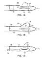
- FIG. 1Ashows an embodiment of the excisional device according to the present invention with the cutting tool in its flat, retracted configuration.
- FIG. 1Bshows the excisional device of FIG. 1A with its cutting tool in an extended, bowed configuration.
- FIG. 1Cshows another view of the excisional device of FIG. 1 A.
- FIG. 2Adepicts the distal region of another embodiment of the excisional device according to the present invention, showing the excisional device together with the external tissue collection attached thereto in the open configuration.
- FIG. 2Bshows the excisional device of FIG. 2A together with the external tissue collection attached thereto in the closed configuration.
- FIG. 2Cshows an embodiment of the proximal region of the excisional device according to the present invention.
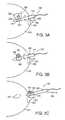
- FIG. 3Adepicts the operation of an embodiment of the excisional device and method according to the present invention.
- FIG. 3Bfurther shows the operation of an embodiment of the excisional device and method according to the present invention.
- FIG. 3Cfurther depicts the operation of an embodiment of the excisional device and method according to the present invention.
- FIG. 4shows a detailed view of a cutting tool suitable for use with the excisional device according to the present invention.
- FIG. 5shows a cross section of the cutting tool, taken along line AA′ in FIG. 4 .
- FIG. 6shows a detailed view of another cutting tool suitable for use with the excisional device according to the present invention.
- FIG. 7shows a cross section of the cutting tool, taken along line BB′ in FIG. 6 .
- FIG. 8shows another embodiment of a cutting tool suitable for use with the excisional biopsy device according to the present invention.
- FIG. 9is a cross-sectional schematic of the tubular member 110 , to illustrate the relative placements of the cutter window 120 and of the transducer 270 about the circumference of the tubular member 110 . Unnecessary details have been omitted for clarity.
- FIG. 10shows an excisional device according to another embodiment of the present invention, in which the tubular member of the excisional device includes an internal lumen through which a removable transducer core may be inserted.
- FIG. 11shows an embodiment of a removable transducer core according to the present invention.
- FIG. 12shows a cross section of the embodiment of the excisional device of FIG. 10 , taken along line AA′.
- FIG. 13shows the removable transducer core of FIG. 11 inserted within an expandable sheath, according to a further embodiment of the present invention.
- FIG. 14shows another embodiment of a soft tissue excisional device assembly according to the present invention, in which a removable transducer core is inserted and secured within the excisional device so that the active element faces out of the transducer window.
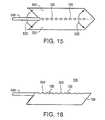
- FIG. 15shows another embodiment of a cutting tool (and method of making same) that is suitable for use within the excisional device according to the present invention.
- FIG. 16shows a view of the completed cutting tool of FIG. 15 .
- FIG. 17shows an embodiment of the method of excisional biopsy method according to the present invention.
- FIG. 18is a top view of a removable cutting probe, according to an embodiment of the present invention.
- FIG. 19is a side view of the removable cutting probe of FIG. 18 , showing the adjustable window slide in a first position, according to an embodiment of the present invention.
- FIG. 20is a side view of the removable cutting probe of FIG. 18 , showing the adjustable window slide in a second position, according to an embodiment of the present invention.
- FIG. 21is a top view of a removable tissue collection probe, according to an embodiment of the present invention.
- FIG. 22is a detail view of a removable tissue collection probe of FIG. 21 .
- FIG. 23is a side view of the removable tissue collection probe of FIG. 21 , showing the tissue collection device thereof in an extended (bowed) configuration.
- FIG. 24Ais a top view of a removable cutting and tissue collection combination probe, according to an embodiment of the present invention.
- FIG. 24Bis a partial cross-sectional view of the removable cutting and tissue collection combination probe of FIG. 24A , taken along lines AA′.
- FIG. 25is a top view of a removable cutting and tissue collection combination probe, according to another embodiment of the present invention.
- FIG. 26is a side view of a removable cutting and tissue collection combination probe, according to a still further embodiment of the present invention, wherein the cutting device and tissue collection devices are shown in their extended configuration.
- FIG. 27Ais a partial cross-section of a tissue collection probe, taken at the level of the tissue collection device thereof, wherein the tissue collection device is in its initial, non-extended configuration.
- FIG. 27Bis a partial cross-section of a tissue collection probe of FIG. 27A , wherein the tissue collection device is in its extended configuration.
- FIG. 27Cis a partial cross-section of a tissue collection probe of FIG. 27B , wherein the tissue collection device has returned to its non-extended configuration after capturing the target tissue.
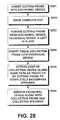
- FIG. 28is a flowchart of a soft tissue treatment method, according to another embodiment of the present invention.
- FIGS. 1A , 1 B and 1 Cshow an embodiment of the distal region 105 of the excisional biopsy device 100 according to the present invention.
- the distal region 105 of the excisional biopsy device 100includes a generally tubular member 110 having a generally tapered distal tip 115 .
- the distal tip 115is configured to penetrate soft tissue, such as breast tissue, lung tissue, liver tissue and the like.
- the distal tip 115 and the distal region 105 of the excisional biopsy device 100present a smooth, and relatively a traumatic profile to the soft tissue in which it is designed to penetrate.
- the tip 115may be sharply pointed and/or may include an energy source (not shown) to facilitate cutting through the tissue.
- the tubular member 110may be formed of rigid and hard plastic, or may be made of stainless steel, for example.
- the tubular member 100is used once and disposed of, for both safety and functional reasons.
- a cutter window 120is disposed within the tubular member 110 .
- the cutter window 120may be, for example, a shallow trench formed in the tubular member 110 .
- the cutter window 120may be a shallow and substantially rectangular trench in the tubular member 110 , or may be, for example, a thin, shallow I-shaped trench.
- the excisional biopsy device 125includes a work element, such as a cutting tool 125 .
- the distal end of the cutting tool 125is attached to the tubular member 110 near its distal tip 115 .
- the distal end of the cutting tool 125may be attached to the distal-most point 121 of the cutter window 120 .
- the cutting tool 125may alternatively be attached to other points within the distal region 105 .
- the distal portion of the cutting tool 125is exposed through the cutter window 120 .
- the remaining portion of the cutting tool 125is disposed within an internal guide or lumen 130 of the generally tubular member 110 .
- the internal guide 130constrains the movement of the cutting tool 125 and allows the cutting tool 125 to freely slide therein, parallel to the longitudinal axis of the tubular member 110 .
- the proximal portion 225 of the cutting tool 125emerges from the internal lumen 130 near the proximal end 215 of the tubular member 110 .
- the proximal end of the cutting tool 125may, for example, include a push or turn knob 226 .
- the push or turn knob 226allows the operator of the excisional biopsy device 100 to selectively push the cutting tool 125 in the distal direction (away from the physician and toward the distal tip 115 ) or retract the cutting tool 125 in the proximal direction (toward the physician and away from the distal tip 115 ).
- the cutting toolis preferably biased in the proximal direction, as symbolized by the arrow 227 in FIG. 2 C.
- This biasingmay be effectuated by means of a spring 228 attached at or near the proximal end 215 of the tubular member 110 and to the proximal portion 225 of the cutting tool 125 .
- the default configuration of the cutting tool 125is the retracted position, wherein the cutting tool 125 lies substantially flat within the cutter window 120 of the tubular member 110 .
- the cutting tool 125when pushed in the distal direction by the physician applying pressure in the distal direction on the push or turn knob 226 or equivalent structure, slides within the internal guide 130 of the tubular member 110 .
- the distal end of the cutting tool 125is attached near the distal end of the tubular member 110 or to the distal-most point 121 of the cutter window 120 , the portion thereof exposed through the cutter window 120 tends to bow outwardly, extending out of the cutter window 120 , as shown in FIG. 1 B.
- the extension out of the cutter window 120 and the degree of bowingmay be controlled by the physician, by appropriate action on the push or turn knob 226 .
- the possible range of extension and bowingis potentially infinite, being limited only by the physician's ability to control the cutting tool 125 by finely pushing and retracting the push or turn knob 226 .
- the degree of extension, as well as the shape of the bowed portion of the cutting tooltherefore, may be controlled by selectively sliding the cutting tool within the internal guide 130 of the tubular member 110 .
- the shape of the bowed portion and the ease with which the distal portion of the cutting tool 125 bows outwardlymay be varied by varying the physical characteristics of the cutting tool 125 .
- the cutting toolis formed of a resilient, readily deformable material that, when unstressed, returns to its original unbiased configuration.
- a nickel titanium alloymay be used for the cutting tool 125 , to allow the cutting tool 125 to exhibit shape-memory characteristics.
- the shape of the cutting tool 125 in its bowed and extended configurationmay be further controlled by varying, for example, the thickness of the cutting tool over the portion thereof exposed through the cutter window 120 .
- a locally thicker portion of the cutting tool 125will not bend as readily as a locally relatively thinner portion thereof. Judiciously varying the thickness, for example, of the cutting tool 125 , therefore, allows the curvature of the bowed portion thereof to be controlled.
- pushing on the push or turn knob 226causes the cutting tool 125 to bow outwardly and extend out from the cutter window 120 of the tubular member 110 , as shown in FIG. 1 B.
- retracting the push or turn knob 226causes the cutting tool 125 to flatten out within the cutter window 120 and to assume a configuration (shown in FIG. 1A ) that may be substantially flush with the outer surface of the tubular member 110 .
- the tubular member 110may easily penetrate soft tissue, such as breast, lung, liver or other soft body tissue.
- the surgeonmakes an incision into the patient's skin, such as the surface of the breast.
- the excisional biopsy device 100then may be directly introduced into the breast tissue, or an expandable sheath (shown at reference numeral 495 in FIG. 13 ) may be introduced into the incision and thereafter expanded as the excisional biopsy device 100 is introduced therein.
- the excisional biopsy deviceis introduced into the breast tissue itself and positioned, for example, adjacent to the lesion in the breast or adjacent the target site from which the excision is to take place.
- the cutting tool 125is in its retracted configuration wherein the portion thereof exposed through the cutter window 120 is substantially flat.
- the excisional device 100in this configuration, therefore, exhibits a smooth and tapered profile to the surrounding tissue.
- the deviceis rotated about its longitudinal axis. The rotation may be carried out manually, or the rotation of the device may be carried out by a motorized unit disposed within the proximal region of the device 100 .
- the surgeoncauses the cutting tool 125 to bow outwardly and to extend from the cutter window 120 .
- the degree of bowing and outward extensionis at least sufficient to include the lesion (such as the targeted microcalcification within the breast) within the space between the cutter window 120 and the cutting tool 125 .
- the cutting tool 125cuts the tissue as the device 100 is rotated, thereby severing the lesion from its surrounding breast tissue mass. By completing at least one revolution within the breast tissue, the cutting tool 125 sweeps a volume of revolution of breast tissue and severs that volume from the main tissue mass. Such volume of revolution includes at least the targeted lesion. Preferably, the volume of revolution severed from the main tissue mass not only includes the targeted lesion, but also includes a margin of healthy tissue surrounding the lesion. The degree of extension and bowing of the cutting tool 125 may be varied within a given revolution of the excisional biopsy device 100 . In this manner, it is possible to exert fine control over the amount of tissue cut away from the main tissue mass, as well as fine control over the shape of the severed mass.
- the severed tissuemay be removed from the main tissue mass. This removal of the severed tissue may be effectuated by any number of means, including the retraction of the excisional biopsy device 100 from the main tissue mass. Alternately, severed tissue extraction may be carried out by means of the structure and method to be described below.
- the cutting tool 125may, as shown in FIG. 1C , be configured as a thin ribbon.
- the thin ribbon 125 shown in FIG. 1Cis preferably sharpened on its leading edge to facilitate cutting through tissue and sometimes fibrous and calcified masses.
- the leading edge of the cutting tool 125is that edge thereof that first comes into contact with the tissue to be severed as the device 100 is rotated. Such a sharpened leading edge is shown in FIG. 4 at reference numeral 127 .
- the width of such a ribbon cutting tool 125is preferably smaller than the width of the cutter window 120 into which it recedes when the cutting tool 125 is retracted in the proximal direction.
- FIG. 8Another embodiment of the cutting tool 125 is shown in FIG. 8 .
- the leading edge of the portion thereof exposed through the cutter window 120may be serrated, including a plurality of teeth 127 .
- the leading edge of the plurality of teeth 127may include a sharpened edge.
- the cutting blade 125 of FIG. 8is believed to be highly effective in cutting through even relatively dense or fibrous tissue while minimizing the torque to be applied to the excisional biopsy device 100 as it is caused to rotate within the main soft tissue mass.
- the cutting tool 125may further comprise an interior lumen 128 running an entire length or a portion of the length of the cutting tool 125 .
- the cutting tool 125may further include a plurality of through holes 126 in the distal portion of the cutting tool 125 exposed through the cutter window 120 .
- the plurality of through holes 126are in fluid communication with the internal lumen 128 .
- the internal lumen 128may be connected, in the proximal portion of the excisional biopsy device 100 , to a fluid reservoir.
- the fluid reservoirwhich may be internal or external to the proximal section of the device 100 , supplies the distal portion of the cutting tool 125 with, for example, anaesthetic (such as, for example, lidocaine) and/or antibiotic fluid.
- anaesthetic and/or antibiotic fluidmay be delivered precisely to the tissue surrounding the cutting tool 125 as it rotates.
- a precisely dosed anaestheticmay be delivered to the very site where it is most needed. As such anaesthetic is delivered only where it is needed, the effect thereof is near instantaneous, and the patient feels little or no pain as the excisional biopsy device 100 according to the present invention is rotated within her breast, or other soft tissue.
- FIG. 5shows a cross-section of the cutting tool 125 of FIG. 4 , taken along line AA′ in FIG. 4 .
- the configuration and materials selectedshould allow the cutting tool 125 to bow and extend out of the cutter window 120 of the device 100 without, however, pinching or substantially disrupting the flow of fluid delivered via the internal lumen 128 of the cutting tool 125 , if the cutting tool 125 is provided with such.
- the cutting tool 125may be made of a shape-memory metal, such as nickel-titanium and/or the proximal portion of the cutting tool 125 may be formed relatively thicker than other portions thereof.
- the cutting tool 125may be formed by a thin sheet of steel or shape memory alloy.
- the sheetmay include a plurality of through holes 126 to allow the anaesthetic or other fluid to be instilled therethrough.
- a small tube 540may be disposed on the sheet, aligned with the through holes 126 .
- the sheetmay be folded in the direction indicated by the arrows 530 , thus securing the tube 540 between the two folded sides of the sheet.
- the edges 550 of the sheetmay be sealed together to render them fluid tight.
- the sides 550 of the sheetmay be welded together or secured by other means known to those of skill in the metal working arts.
- the edges 560 between the through holes 126may be sharpened, to allow the cutting tool 125 to efficiently cut through soft tissue.
- the tube 540may deliver anaesthetic or other fluid to the cutting tool 125 , which delivers minute amounts thereof precisely where it is needed: where the cutting edges 560 of the cutting tool 125 , thereby affording the patient immediate relief and minimizing the amount of anaesthetic that need be delivered.
- the proximal end of the tube 540may be in fluid communication with an anaesthetic reservoir (not shown) and/or an anaesthetic pump (also not shown).
- the cutting tool 125may include a thin wire, such as shown at 125 in FIGS. 6 and 7 .
- an external radio frequency (hereafter, RF) power source 240(shown at 240 in FIG. 2C ) supplies the cutting tool 125 with RF energy via two bipolar electrodes (not shown) attached to the cutting tool 125 of FIG. 6 .
- RFradio frequency
- Other energy sourcesmay also be used within the context of the present invention, RF power being discussed herein for illustrative purposes only.
- the RF power delivered by the RF power source 240allows the cutting tool 125 of FIG. 6 to become an electrosurgical cutting and/or an electrocoagulating tool by selectively varying the power applied to the cutting tool 125 .
- Suitable generators for such an electrosurgical cutting device 125are known to those of skill in this art.
- An example of such a suitable generatoris described in U.S. Pat. No. 4,903,696 issued Feb. 27, 1990 and assigned to Everest Medical Corporation, Brooklyn Center, Minn., the disclosure of which is incorporated herewith in its entirety.
- the cutting tool 125 of FIGS. 6 and 7includes an internal lumen 128 and a plurality of through holes 126 to allow anaesthetic or other fluid to be delivered to the surrounding tissue as the cutting tool 125 cuts through the soft tissue as the device 100 is rotated.
- the excisional biopsy device 100cuts out a (not necessarily symmetrical) volume of revolution as it cuts through the soft tissue upon rotation of the generally tubular member 110 .
- This severed mass of tissuemay be stabilized using an extendable tissue anchoring device, which anchoring device also assists in the retrieval of the severed tissue sample from the breast.
- the anchoring devicemay, for example, include a suction device or other substantially rigid anchor member to anchor the tissue sample.
- the severed tissue samplemay be collected in a tissue collection device, as shown at reference numeral 260 in FIGS. 2A and 2B .
- the tissue collection device 260is attached externally to the tubular member 110 , and preferably also to the trailing edge of the cutting tool 125 .
- the tissue collection device 260is preferably formed of a thin and flexible plastic membrane shaped like a bag.
- the opening of the bag-shaped collection device 260is preferably co-extensive with the opening 120 and is preferably attached to the tubular member 110 and to the trailing edge of the cutting tool 125 . In this manner, the opening or “mouth” of the bag-shaped collection device 260 opens and closes along with the bowing and retraction, respectively, of the cutting tool 125 .
- the “mouth” of the bag-shaped collection device 260is opened when the cutting tool 125 is bowed and extended out of the cutter window 120 and substantially closed when the same is retracted within the cutter window 120 , as the two edges (one attached to the tubular member 110 just adjacent to the edge of the cutter window 120 and the other attached to the trailing edge of the cutting tool 125 ) of the collection device are then pressed together.
- the cutting tool 125may be caused to bow and to extend outwardly from the cutter window 120 and caused to cut tissue coming into contact therewith.
- the tissue between the cutting tool 125 and the tubular member 110tends to advance toward and into the collection device.
- the “mouth” or opening of the bag-shaped collection device 260is also correspondingly open, allowing the severed tissue to collect therein.
- the cutting tool 125may be retracted and caused to assume a configuration wherein it is disposed within the recessed cutter window 120 , substantially flush with the outer surface of the tubular member 110 , as shown in FIG. 2 B.
- the collection device 260is closed, thereby securing the excised tissue sample therein.
- the device 100may then be safely retracted from the main tissue mass, such as the breast. As the excised sample is physically isolated from the remaining tissue mass, the probability of seeding the surrounding tissue with potentially abnormal cells is markedly decreased.
- the excisional device 100allows the surgeon to obtain adequate margins of healthy tissue surrounding the target lesion by choosing the degree of bowing and extension of the cutting tool 125 . In this manner, the integrity of the lesion itself is not violated, thereby maintaining tissue architecture intact.
- the collection device 260is preferably formed of a thin and flexible membrane, it is able to lay substantially flat against the outer surface of the tubular member 110 or slightly recessed within the cutter window 120 during insertion thereof into the soft tissue.
- the collection device 260offers little additional drag and resistance to the device 100 as it is inserted into the incision made in the patient's skin during or prior to the procedure.
- Suitable materials for the tissue collection device 260include plastics and nylon, for example. Any strong adhesive may be utilized to secure the tissue collection device 260 to the tubular member 110 and to the cutting tool 125 . Other means of securing the collection device 260 may also be employed without, however, departing from the scope of the present invention.
- the tissue collection device 260may be formed of a material other than specifically enumerated herein while remaining within the spirit of the present invention.
- the shape and size of the tissue collection device 260are such as to minimize drag on the excisional biopsy device 100 as it is inserted and rotated into the tissue.
- the tissue collection device 260preferably should be only as large as necessary to contain the excised tissue sample.
- the excisional biopsy device 100is preferably accurately positioned adjacent to the lesion within the breast or other organ. Toward that end, the present invention allows the surgeon to gain near real time or real time information as to the internal structure of the soft tissue during the procedure itself.
- the present inventionmay include a transducer 270 mounted within the distal portion of the tubular member 110 . This transducer 270 is preferably adapted to image tissue about to be cut by the cutting tool 125 as the excisional biopsy device 100 is rotated within the soft tissue.
- the transducer 270preferably generates information relative to the tissue about to be cut—that is, tissue that that has not yet been brought into contact with the cutting tool 125 as the tubular member 110 rotates about its longitudinal axis.
- the rotational speed of the excisional biopsy device 100is preferably quite slow (the rotation may be manually carried out or may be caused by a slow moving motorized unit attached to the tubular member 110 )
- the surgeonmay evaluate the information generated by the transducer 270 and may, based upon this information, vary the degree of bowing and extension of the cutting tool 125 .
- the transducer 270when the device 100 is positioned adjacent to the lesion of interest and rotated, the transducer 270 will detect the presence and location of the lesion before the lesion comes into contact with the cutting tool 125 . After the lesion has been detected by the transducer 270 , the surgeon may push on the push or turn knob 226 or other structure that causes the cutting tool to bow and extend from the cutter window 120 . The lesion (and preferably an adequate margin of healthy tissue) will then be severed from the main mass, and optionally collected, for example, in the tissue collection device 260 . When the transducer 270 indicates that the rotation of the tubular member has brought the cutting tool 125 past the lesion, the cutting tool 125 may be retracted within the cutter window 120 . The cutting, it can be seen, may be specifically tailored to the size and shape of the lesion within the main tissue mass in near real time or in real time, thereby allowing the surgeon to excise all of the tissue required and only the tissue that is necessary to achieve the intended results.
- the transducer 270is an ultrasound sensor mounted substantially flush with the external surface of the tubular member 110 .
- the ultrasound sensor 270is preferably electrically connected, via a communication channel such as electrical conductors, to at least one data processing and display device, shown at reference 250 in FIG. 2 C.
- the data processing and display device(s) 250allows the surgeon to see, in near real time or in real time, the internal structure of the tissue about to be cut by the cutting tool 125 .
- the present inventionis an intra-tissue ultrasound imaging device that may, but need not include a cutting tool, such as referenced by numeral 125 in the figures.
- the (e.g., ultrasound) transducersweeps a plane (graphically shown at 280 in FIG. 3A ) within the tissue ahead of the work element, such as cutting tool 125 .
- the surgeonmust balance the required resolution (i.e., the smallest feature that must be discernable) with the degree of penetration of the ultrasound waves within the tissue and the intensity of the ultrasonic waves generated. In general, higher frequencies allow better resolution. However, high frequencies do not penetrate the tissue as far as do lower frequency ultrasound waves.
- the ultrasound transducer 270is tuned within the range from about 5 MHz to about 20 MHz.
- the ultrasound transducer 270is tuned within the range of about 7.5 MHz to about 20 MHz.
- the ultrasound transducermay be tuned within the range of about 10 MHz to about 13 MHz.
- the transducer 270To effectively image the internal tissue structure prior to cutting it with, for example, the cutting tool 125 , the transducer 270 must be positioned within the tubular member 110 away from the cutting tool 125 . With reference to FIG. 9 , the transducer 270 may be disposed within the tubular member at an angle ⁇ relative to the cutting tool 125 . The angle ⁇ is preferably no smaller than that necessary to effectively control the operation of the work element (such as cutting element 125 ) in response to information gathered from the transducer 125 as the tubular member 110 rotates.
- This angle ⁇is dependent at least upon the rotational speed imposed upon the tubular member 110 and upon the time necessary for the surgeon to assimilate the information generated by the transducer and to effectively control the cutting tool 125 in response to such information.
- the angle ⁇is less than about 180 degrees.
- the excisional biopsy device 100may include a variety of work elements in place of or in addition to the cutting tool 125 .
- work elementsinclude, for example, an abrasive device, a reciprocating cutting device, an electrosurgical device or a vibrating device.
- FIGS. 3A , 3 B and 3 Cillustrate an embodiment of the excisional biopsy method according to the present invention.
- FIGS. 3A-3Cillustrate an embodiment of the present invention within the context of breast surgery, it is to be understood that the present inventive method is equally applicable to other soft tissue masses, such as, for example, lung, thyroid or liver tissue, with only minor modifications that will become apparent to skilled practitioners in this art.
- a small incision 331is made in the breast 310 , preferably in the peri-areolar region.
- the breastis stabilized, using, for example, the breast stabilizing devices disclosed in U.S. patent application Ser. Nos. 09/158,215 or 09/200,661 referred to above.
- the portion of the device 100 that remains outside of the soft tissuemay include attachment means (not shown) for clamping the device to a rim structure, for example, to allow stable operation and precise guidance thereof.
- the small incisionis preferably made on the border of the areola 330 surrounding the nipple 320 , as this provides a better cosmetic scar than on the skin on the side of the breast 310 .
- an expandable sheath(an example of which is shown at reference numeral 495 in FIG. 13 ) may be inserted into the breast tissue.
- the excisional biopsy device 100is inserted into the breast tissue and positioned adjacent the lesion 300 , which may be, for example, a microcalcification or other abnormal lesion. Once in position, the device 100 is rotated, for example, in the direction indicated in FIG. 3 A.
- the portion of the excisional biopsy device 100 that remains outside the soft tissuemay have a greater diameter than the portion thereof that is designed to penetrate the soft tissue. This aids in manual rotation of the device 100 . In the configuration depicted in FIG.
- the cutting tool 125is retracted within the cutter window 120 and the tissue collection device 260 , if present, is substantially flat against the external surface of the tubular member 110 .
- the device 110is rotated about its longitudinal axis and the transducer 270 is energized, the information therefrom being transmitted to, for example, the display device 250 shown in FIG. 2 C.
- the surgeongauges the size, shape and location thereof and controls the bowing and extension of the work element, such as cutting tool 125 based on the information received from the transducer 270 and displayed upon the display 250 .
- FIG. 3Bdepicts the situation wherein the lesion 300 has been imaged and the surgeon has extended the cutting tool 125 to sever the lesion 300 from the surrounding breast tissue.
- the severed tissuemay be received and collected in a tissue collection device 260 , as the device 100 rotates.
- Anaesthetic and/or antibiotic (or other) fluidsmay be delivered directly to the affected tissue by through holes 126 (best seen in FIGS. 2A , 2 B and FIGS. 4 - 7 ), greatly decreasing pain during the procedure
- the cutting tool 125is retracted within the cutter window 120 . This closes the tissue collection device 260 , if present, and allows the entire device 100 to be retracted from the breast in the direction of arrow 350 , as shown in FIG. 3 C. If the tissue collection device 260 is present, the lesion 300 will be isolated from surrounding tissue by the membrane of the tissue collection device 260 , thus minimizing any possibility of seeding potentially abnormal cells to surrounding breast tissue. Moreover, the tissue architecture of the retrieved lesion 300 is substantially preserved, thereby allowing accurate histopathology to be performed upon the entire mass excised from the breast.
- any compression such tissue may undergois believed to be solely due to the retraction of the device back through the entrance track of the device 100 in the uncompressed breast tissue.
- the push or turn knob 226may be acted upon to extend and bow the cutting tool 125 , thereby allowing the excised lesion to be retrieved from the tissue collection device 260 for examination.
- conventional suction meansmay be employed to extract the severed lesion from the surrounding breast tissue. Bleeding is controlled by suitably varying the RF or other power source applied to the electrosurgical cutting tool 125 , if present, to stem the bleeding by cauterizing the tissue coagulating the blood.
- the transducer 270is replaced by a removable transducer core 400 .
- the removable transducer core 400includes an active element 440 configured to perform intra-tissue imaging and of relaying information back to a display device (shown in FIG. 14 ) via a communication channel, such as shown at reference numeral 460 .
- the communication channel 460may be wireless or may include, for example, optical fibers and/or electrical conductors.
- the active element 440may draw power from an internal battery (not shown) or from a power source, such as shown at reference numeral 480 .
- the active element 440may include an ultrasound transducer.
- the removable transducer core 400preferably includes a generally tubular shaft 430 .
- a proximal section 450is included near the proximal portion of the transducer core 400 .
- the excisional device 100 of FIG. 10defines an internal lumen 420 through which the removable transducer core 400 may be inserted.
- the excisional device 100is used once and disposed of, for safety and functional reasons.
- the removable transducer core 400may either be disposable or re-usable for a limited number of uses.
- the generally tubular member 110 of the excisional device 100includes a transducer window 410 .
- the proximal section 450 of the core 400preferably snaps into a locked configuration with the proximal end of the excisional device 100 .
- the active element 440 of the transducer core 400is aligned with and faces the transducer window 410 , to allow the active element 440 to image the lesion and the surrounding tissue therethrough.
- the distal-most tip thereofmay include an (mono or bipolar) RF electrosurgical element or wire, as indicated at reference numeral 116 , which may be energized by an RF source, as shown at 240 in FIGS. 2C and 14 .
- FIG. 11shows an embodiment of the removable core 400 according to the present invention.
- the removable core 400may advantageously be used independently of the excisional device 100 , the removable core 400 includes a distal tapered tip 470 , to allow it to easily penetrate soft tissue. Moreover, its thin profile allows the surgeon to insert the removable core 400 within soft tissue without, however, unduly damaging the tissue or making a large incision.
- the removable core 400allows the surgeon to precisely localize the lesion to be excised from within the tissue itself.
- the active element 440 of the removable core 400may include an ultrasound transducer having similar characteristics as the sensor 270 , and may be used alone or in addition to surface ultrasound to localize the lesion with a great degree of precision.
- FIG. 12shows a cross section of the embodiment of the excisional device 100 of FIG. 10 , taken along line AA′.
- the cutting tool 125is exposed through the cutter window 120 .
- the window 120may, as shown in FIG. 12 , include support guides 122 to support and guide the cutting tool 125 as it is outwardly extended and bowed.
- the tissue collection device 260for clarity, is not shown in either FIGS. 10 or 12 .
- the tubular member 110may include a recessed section 131 .
- the recessed sectionprovides space for the collected (e.g., bagged) tissue sample in the tissue collection device 260 when the excisional device is removed from the soft tissue mass.
- the collected tissue sample within the tissue collection device 260does not protrude from the generally smooth outer surface of the excisional device 100 upon retraction of the latter from the soft tissue mass from which the tissue sample is excised.
- the internal lumen 420allows the removable core 400 to slide therein and to properly position the active element 440 facing the transducer window 410 .
- FIG. 13shows the removable core 400 inserted within an expandable sheath 495 .
- the expandable sheathincludes a proximal base section 510 .
- Attached to the proximal base section 510is a generally cylindrical expandable meshwork 500 of, for example, plastic or nylon fibers.
- the meshwork 500may be somewhat tapered at its distal end 520 , to provide a smooth transition between the expandable meshwork 500 and the removable core device 400 .
- the proximal section 450 of the core 400may snap-fit to the proximal base section 510 of the expandable sheath 495 , so as to be securely and removably attached thereto. As shown in FIG.
- the expandable meshwork 500expands just enough to accommodate the removable core 400 inserted therein.
- the expandable sheath 495 and removable core 400 assemblymay be inserted within the soft tissue together, to allow the surgeon to image the lesion prior to inserting the somewhat greater diameter excisional device 100 therein. Thereafter, the surgeon may retract the removable core 400 from the expandable sheath 495 , leaving the expandable sheath 495 in place within the soft tissue, such as the breast.
- FIG. 14shows another embodiment of a soft tissue excisional device assembly 600 according to the present invention.
- the removable core 400is inserted and secured within the excisional device 100 so that the active element 440 faces out of the transducer window 410 .
- the tissue collection device 260is not shown, for clarity.
- the excisional device 100is shown inserted within the expandable sheath 495 .
- the excisional device 100in FIG. 14 , is shown inserted within and past the distal end 520 of the meshwork 500 , so the distal portion of the excisional device 100 including the cutting tool 125 and the transducer window 410 extends therethrough.
- the meshwork 500in FIG.
- the proximal portion of the excisional device 100may extend from the proximal base section of the expandable sheath 495 . This allows the push or turn knob 226 (a turn knob 226 shown in FIG. 14 ) to be manually accessible to the surgeon.
- a number of peripheral devicesmay be connected to the assembly 600 . Examples of such include a core power source 480 , which may be, for example, an electrical source for an ultrasound transducer, one or more data processing and display devices 250 on which the internal structure of the tissue imaged by the active element 440 of the core 400 may be displayed, suction means 490 , a cutting tool power source (a variable RF energy source, for example), and/or other devices 590 .
- the suction device 490may provide a suction force to the window 120 through an internal lumen to facilitate cutting of the tissue by the cutting tool 125 .
- the excisional device assembly 600may be rotated in toto, or the excisional device 100 may be rotated independently of the expandable sheath 495 , depending upon the degree of friction between the two.
- the excisional device 100is removable from the expanded sheath 495 shown in FIG. 14 , while leaving the expanded sheath 495 in place within the soft tissue. In this manner, after retraction of the excisional device 100 from the sheath 495 , the sheath 495 remains in place within the soft tissue to allow other instruments to be inserted therethrough.
- the removable core 400may, after the excisional procedure proper, be re-inserted through the expanded sheath 495 to the excision site.
- the surgeonmay cause the active element 440 of the removable core 400 to become energized, to image the excision site to insure that the complete lesion has been removed from the soft tissue mass.
- the surgeonmay rotate the removable core 400 within the expanded sheath 495 while observing the display or displays for signs of the lesion. If none is found, it is probable that the entire lesion has been successfully removed and the surgeon may then retract the core 400 from the sheath 495 and the sheath from the tissue mass and repair the incision made prior to inserting the assembly therein.
- the surgeonmay choose to remove both the expanded sheath 495 and the core 400 simultaneously.
- FIG. 17shows an embodiment of the method of excisional biopsy method according to the present invention.
- the soft tissue from which the lesion is to be excisedis breast tissue and that the active element 440 of the removable core 400 is an ultrasound transducer.
- the removable core 400 and the active element 440in FIG. 17 , are together abbreviated as “US CORE”, a shorthand expression for the phrase “ultrasound core” and the word “assembly” is abbreviated to “Ass'y”.
- the steps shown in FIG. 17constitute but a broad outline of one possible embodiment of the present inventive method. Therefore, other additional steps may be inserted between the steps shown in FIG. 17 , or other steps may be substituted for some of the displayed steps without, however, departing from the scope of the present invention.
- step S 1the lesion within the breast is grossly targeted, using, for example, standard or stereotactic surface ultrasound.
- a rough estimate of the location of the lesion within the breastis obtained.
- the surgeonafter having located the general location of the lesion, may mark the location thereof on the ultrasound display or displays and/or on the corresponding surface of the breast, with an “X”, for example.
- the breastis stabilized in step S 2 .
- the breastis stabilized in an uncompressed or slightly expanded state, in the manner disclosed in the commonly assigned and co-pending U.S. patent application Ser. Nos. 09/158,215 or 09/200,661 previously discussed and incorporated by reference herein.
- the woman's other breastis preferably placed within a counterpart breast stabilizing device, which helps to immobilize the woman during the procedure.
- One of the ultrasound ports of the breast stabilizing deviceis aligned with the lesion, for example, by aligning one of its ultrasound ports with the marked location on the breast. Suction is then applied to the breast stabilizing device, in the manner described in the above-referenced application and a correctly oriented surface ultrasound device is secured to the ultrasound port of the stabilizing device.
- Other means of stabilizing the breastmay also be used without, however, departing form the present invention.
- step S 3an entry site on the breast is chosen.
- the peri-areolar regionis chosen as the incision site, as scars within the peri-areolar region are less visible than scars in more exposed regions of the breast and for other anatomical reasons.
- the incision siteis then anaesthetized, both on the skin surface and subcutaneously.
- a small incisionis made at the chosen incision site.
- the incisionis large enough to accommodate the expandable sheath 495 with the removable core 400 inserted therein.
- step S 4the expandable sheath 495 , together with the removable core inserted therethrough, is inserted into the incision made in step S 3 .
- the sheath 495 /core 400 assemblyis navigated adjacent to the lesion. If the sheath 495 /core 400 assembly can be properly positioned adjacent to the target lesion, the method according to the present invention proceeds to step S 5 . If the sheath 495 /core 400 assembly cannot be properly positioned adjacent to the target lesion, all or a portion of the above-detailed steps are repeated until proper positioning of the sheath 495 /core 400 assembly is achieved, adjacent to the target lesion.
- step S 4the core 400 is removed from the expandable sheath 495 and the expandable sheath 495 is left in place within the breast, as shown in step S 5 .
- step S 6the removable core 400 is inserted within the internal lumen 420 of the tubular member of the excisional device 100 and locked securely in place, so that the active element 440 (in this case, an ultrasound transducer) is aligned with and faces out of the transducer window 410 of the device 100 .
- the excisional device 100is advanced through the expandable sheath 495 .
- the sheath 495then expands within the breast tissue to accommodate the somewhat larger diameter of the excisional device 100 .
- the excisional device 100is advanced past the tapered distal end 520 of the sheath 495 , so the assembly including the sheath 495 , the excisional device 100 and the removable core 400 is positioned adjacent to the target lesion within the breast tissue, as shown in step S 7 .
- step S 8the correct position adjacent the target lesion and the correct rotational orientation of the aforementioned assembly ( FIG. 14 ) are confirmed, using surface ultrasound and/or the core ultrasound 400 .
- the active element 440 of the core 400is particularly well suited for this task, as the excisional device 100 may be rotated within the tissue, and positioned so the cutting tool 125 is properly positioned to allow it to rotate, extend and bow outwardly in such a manner as to precisely sever the lesion from the surrounding tissue with an adequate margin of healthy tissue.
- the ultrasound transducer 440as it rotates along with the excisional device 100 , images the lesion before the cutting tool 125 cuts it, thereby allowing the surgeon to optimally deploy the cutting tool based upon his or her observation of the imaged tissue on a display or displays.
- the surgeonmay activate an anaesthetic infusion, the anaesthetic being delivered by the cutting tool 125 via the plurality of through holes 126 , best seen in FIGS. 4 and 6 .
- Step S 9may be skipped if the cutting tool 125 does not provide for through holes 126 or if the surgeon does not deem it necessary to anaesthetize the tissue during the rotation of the cutting tool 125 .
- the tissuemay have been previously anaesthetized.
- the cutting tool 125is extended using, for example the push or turn knob 226 shown in FIGS. 2C and 14 , thereby causing the cutting tool 125 to extend from the window 410 and to bow outwardly, as shown in step S 10 .
- the sheath 495may rotated along with the excisional device 100 .
- the degree of extension and bowingmay be finely controlled by the surgeon as the excisional device 100 is rotated, either manually or by a motorized unit (not shown) coupled thereto.
- the cutting toolAs the cutting tool is rotated, the severed tissue sample is preferably collected (e.g., bagged) in a tissue collection device 260 (FIGS. 2 A and 2 B), as shown at step S 11 .
- the blood vesselsmay be coagulated as the cutting tools rotates and cuts the tissue, or afterwards.
- step S 12after the excisional device 100 has completed at least one revolution within the breast and has cut a volume of revolution therein, including at least the target lesion and preferably a margin of healthy tissue surrounding the lesion, the excisional biopsy device 100 and removable core 400 assembly are retracted through the sheath 495 , leaving the sheath 495 once again in place within the breast.
- the tissue collection device 260 and the tissue sample it encloseslie within the recessed section 131 of the generally tubular member 110 . In this manner, the filled collection device 260 does not protrude or protrude too much from the surface of the tubular member 110 , thereby allowing the retrieved tissue sample to be readily retracted with the excisional device 100 through the sheath 495 .
- the core 400may be retracted from the device 100 and re-inserted through the sheath 495 left in place within the breast.
- the core 400is then advanced adjacent to the excision site, and rotated to allow the surgeon to image the excision site to insure that the entire lesion has indeed been removed, as shown in step S 13 .
- Some or all of the above stepsmay be repeated should the imaging of the excision site by the core 400 within the sheath 495 reveal that a portion of the target lesion was not excised. Assuming that the entire target lesion has been removed, the incision is repaired by, for example, suturing the peri-areolar incision site. The method ends at step S 16 .
- FIG. 18shows a top view of a removable cutting probe 700 , according to an embodiment of the present invention.
- the removable probe 700includes a proximal portion 702 and a distal portion 704 .
- the proximal portion 702may include cutting tool extending means 718 and the distal portion 704 may include a cutting tool 706 , such as a wire or ribbon cutting tools described above.
- the cutting tool 706may be sharpened on its leading edge.
- the first removable probe 700is preferably configured to fit at least partially within the tubular member 110 to enable the cutting tool 706 to selectively bow out of and to retract within a first window 710 when the cutting tool extending means 718 are activated.
- the first window 710is defined within the surface of the removable probe 700 .
- the removable cutting probe 700may be inserted within the internal lumen 420 (or guided within guides internal to the tubular member 110 ) of the tubular member 110 in such a manner that the window 710 defined within the probe 700 faces the window 410 ( FIG. 10 ) defined within the surface of the tubular member 110 .
- the tubular member 110may define one or more additional windows similar to that shown at 410 in FIG. 10 .
- the removable probe 700(and those to be described relative to FIGS. 21-27C ) may be inserted within the tubular member 110 such that the window 710 faces one of these additional windows (hereinafter collectively referenced by numeral 410 ) and/or the window 410 in FIGS. 10 and 12 .
- the cutting tool 706may include an RF cutting tool.
- the RF cutting tool and the removable cutting probe 700may be connected to an RF power source, such as shown at 240 in FIGS. 2C , 14 and 18 .
- the RF cutting toolfor example, may be either a monopolar or a bipolar RF cutting tool, as disclosed above.
- the removable cutting probe 700may also include an internal guide 712 (or may define an internal lumen) to enable the cutting tool 706 to slide within the removable cutting probe 700 when cutting tool extending means 718 are activated.
- the cutting tools extending means 718are shown as a thumb-activated dial in FIGS. 18-20 .
- any other means of advancing and retracting the cutting tool 706may also advantageously be used within the context of the present invention.
- the distal portion 704 of the removable cutting probe 700may further include a window slide 708 disposed within the window 710 and the proximal end 702 may further include window slide extending means 716 .
- the window slide 708is coupled to the window slide extending means 716 and is guided within the removable cutting probe 700 by an internal guide or lumen 714 along the length of the probe 700 .
- the window slide 708is configured to selectively cover a portion of the window 710 when the window slide extending means 716 are activated.
- the window slide extending means 716are shown in FIGS. 18-20 as thumb-activated dials. However, any means of extending the window slide 708 within the window 710 to selectively cover a portion thereof may readily be implemented within the removable cutting probe 700 , as those of skill will recognize.
- the window slide 708covers a portion of the window 710 to selectively vary the width of the window 710 through which the cutting tool 706 is allowed to extend or bow.
- FIG. 19is a side view of the removable cutting probe of FIG. 18 , showing the adjustable window slide 708 in a first position, according to an embodiment of the present invention
- FIG. 20is a side view of the removable cutting probe of FIG. 18 , showing the adjustable window slide 708 in a second position.
- the window slide 708is less engaged within the window 710 and it is in FIG. 20 . Consequently, the cutting tool 706 in FIG. 19 is able to extend over a wider portion of the window 710 than it is able to when the window slide 708 is in the relatively more engaged position shown in FIG. 20 .
- the window slide 708may be further engaged within the window 710 ( FIG. 20 ) when the physician wants to cut a smaller tissue specimen than would otherwise be cut when the probe 700 is in the configuration illustrated in FIG. 19 .
- FIG. 21is a top view of a removable tissue collection probe 800 , according to an embodiment of the present invention.
- the removable tissue collection probe 800includes a proximal section 802 and a distal section 804 .
- the proximal section 802may include a tissue collection device extending means 814 and the distal section 804 may include a tissue collection device 808 , 810 .
- the removable tissue collection probe 800may be configured to fit at least partially within the tubular member 110 to enable the tissue collection device 808 , 810 to extend out of and to retract within the window 410 (or other window defined within the surface of the tubular member 110 ) when the tissue collection device extending means 814 are activated.
- the tissue collection device extending means 814may be configured as a thumb-dial or a wheel or as any other suitable means for extending the tissue collection device 808 , 810 , such as a lever, for example.
- the tissue collection device 808 , 810may include a ribbon or wire 808 that may be configured to extend or bow out of and retract back within the window 806 in the probe 800 .
- Attached to the wire or ribbon 808is a thin flexible sheet of non-porous or porous material 810 , such as polyethylene or polyethylene teraphthalate (PET), for example.
- PETpolyethylene or polyethylene teraphthalate
- a non-porous materialis preferable to isolate the tissue specimen from the surrounding tissue. Such isolation is used to prevent possible cancer cells from seeding along the insertion track of the probe and/or the excisional device 100 .
- a non-porous flexible material 810prevents fluid and cell leakage therefrom and insures isolation of the cut tissue specimen.
- the thin flexible sheet of material 810may be dispensed from a roll 814 of such material, the free end of the sheet 810 being attached to the ribbon or wire 808 .
- the roll 814may dispense the material 810 as the ribbon or wire 808 is extended or bowed out of the window 806 (and out of a corresponding (facing) window in the tubular member 110 ) and completely or partially encompass or encapsulate the tissue specimen (see reference numeral 1008 in FIGS. 27A-27C ) as the tubular member 110 and contained probe 800 are rotated within the patient's soft tissue.
- the tissue collection device 808 , 810may be configured as shown and described relative to FIGS. 2A and 2B , for example.
- FIGS. 27A through 27Cshow still another tissue collection device configuration, as will be described below.
- FIG. 23shows a side view of the removable tissue collection probe 800 of FIG. 21 , showing the tissue collection device 808 , 810 in an extended configuration.
- the tissue collection device extending means 814has been (manually, for example) activated to cause the bowing of the tissue collection device 808 , 810 out of the window 806 defined within the tissue collection probe 800 .
- This bowing, or extension, of the wire or ribbon 808causes the thin sheet of material 810 to be unrolled or otherwise deployed.
- the tissue collection probe contained thereinis also rotated, in the direction shown by arrow 816 , for example.
- the tissue collection device extending means 814may be activated extended (bowed) so as to cause the ribbon or wire 808 to follow substantially the same path within the tissue, as did the cutting tool 706 . This eases the collection process, as the ribbon or wire 808 merely follows the path of the incision previously made by the cutting tool 706 or 125 . As the excisional device is rotated, the tissue specimen (i.e., lesion) is captured within the sheet of material or bag 810 , whereupon it may readily be extracted from the patient for pathological examination.
- tissue specimeni.e., lesion
- FIG. 24Ais a top view of a removable cutting and tissue collection combination probe 900 , according to an embodiment of the present invention
- FIG. 24Bis a partial cross-sectional view of the removable cutting and tissue collection combination probe 900 of FIG. 24A , taken along lines AA′.
- the combination cutting and tissue collection removable probe 900includes a proximal end 902 and a distal end 904 .
- the proximal end 902may include cutting tool extending means 908 and tissue collection device extending means 906 .
- the extending means 906 , 908may be configured as thumb dials or as any devices that are operative to extend the tissue collection device 918 and/or the cutting tool 914 , such as a lever, for example.
- the wires and/or ribbons that constitute the cutting tool 914 and part of the tissue collection device 918extend from the extending means 906 , 908 along the length of the probe 900 .
- the cutting tool 914 and the wire or ribbon of the tissue collection device 918may be guided within the probe 900 by guides 912 and 910 , respectively.
- the cutting tool 914 and the wire or ribbon of the tissue collection device 918may be guided within the probe 900 by one or more internal lumens defined therein, in a manner similar as described relative to internal lumen 420 of tubular member 110 , shown in FIG. 10 .
- the cutting tool 914may be energized by RF energy, the cutting tool 914 may be separated from the tissue collection device 918 by an air gap 920 (for example) of sufficient width to prevent arcing therebetween.
- FIG. 25is a top view of a removable cutting and tissue collection combination probe 925 , according to another embodiment of the present invention.
- the embodiment of FIG. 25differs from that shown in FIG. 24A in that the cutting tool 914 is separated from the tissue collection device 918 not by an air gap, but by an insulating material 922 , such as a flexible plastic insulator.
- the cutting tool 914includes an RF cutting device
- the cutting tool 914is electrically coupled to an RF power source, such as shown at 240 .
- the configuration of the proximal end 902 of the probe shown in FIG. 25also differs from that shown in FIG.
- a single extending means 926is configured to activate both the cutting tool 914 and the tissue collection device 918 , as the cutting tool 914 and the tissue collection device 918 are mechanically coupled to one another.
- the assembly including the mechanically coupled cutting tool 914 and tissue collection device 918is coupled to the extending means 926 along the length of the probe, and is guided there along by an internal guide or lumen 924 .
- FIG. 26is a side view of a removable cutting and tissue collection combination probe 950 , according to a still further embodiment of the present invention, wherein the cutting tool 930 and the tissue collection device 932 , 934 are shown in their extended (bowed) configurations.
- the probe 950includes a proximal portion 902 and a distal portion 904 .
- the proximal portion 902includes a cutting tool extending means 926 that is configured to activate the cutting tool 930 and a tissue collection device extending means 944 that is configured to activate and extend the tissue collection device 932 , 934 .
- the tissue collection device 932 , 934may include a ribbon or wire 932 that is adapted to bow (extend) out of and to retract back within a first window 942 defined within the probe 950 .
- a thin and flexible sheet of material 934is attached to the trailing edge of the wire or ribbon 932 to encapsulate or otherwise capture the cut tissue specimen upon activation of the tissue collection device 932 , 934 and rotation of the tubular member 110 and probe 950 , in the direction indicated by arrow 928 , for example.
- the cutting tool 930(including an RF cutting tool, for example) is configured to extend out of and retract back into a second window 936 .
- Both of the first and second windows 942 , 936when the probe 950 is inserted into the tubular member 110 , are aligned with corresponding windows defined within the tubular member 110 .
- One such windowis shown in FIG. 10 at reference numeral 410 .
- the combination probe 950 of FIG. 26may also include a plurality of through holes in fluid communication with an internal lumen 940 defined within the internal wall of the probe 950 .
- the internal lumen 940is in fluid communication with a port 942 , which may be disposed at the proximal end of the probe 950 .
- the through holes 938may be utilized for the delivery of a fluid to the patient during the excisional procedure, such as antibiotic agents, analgesic agents or most any pharmaceutical agent. Such agents may be administered to the patient from the port 942 .
- the port 942may be coupled to suction and the through holes 938 may be utilized to suction out the excisional site of smoke, blood or other bodily fluids during or after the excisional procedure.
- more than one port 942may be provided in the proximal portion 902 and more than one lumen 940 may be defined along the length of the probe 950 .
- the additional lumenmay be in fluid communication with selected through holes 938 .
- FIGS. 18-26have been described as removable probes adapted to fit at least partially within the excisional device 110 , it should be noted that they need not be utilized therewith, and may be utilized independently thereof.
- the cutting probe of FIGS. 18-20may be inserted and operated within soft tissue by themselves, without being inserted in the excisional device 110 of FIG. 10 .
- the tissue collection probe 800may be utilized without the excisional device 110 .
- the cutting probe 700 of FIGS. 18-20may be utilized to cut the tissue specimen from the surrounding soft tissue, whereupon the tissue collection probe 800 of FIGS. 21-23 may be inserted after removal of the cutting probe 700 .
- the features of each of the probes of FIGS. 18-27Cmay be combined to best suit the application envisaged. The present invention, therefore, is not to be limited by the specific embodiments illustrated in FIGS. 18-27C , as various other combinations of the disclosed features are possible, as those of skill will readily recognize.
- FIG. 27A-27Care partial cross-sections of a tissue collection probe 1000 , taken at the level of the tissue collection device 1018 thereof, as the probe 1000 captures and encapsulates a tissue specimen (lesion) 1008 within the patient's soft tissue, such as the breast.
- the tissue collection device 1018includes a thin sheet of flexible material 1002 , which is folded on itself. One end of the thin flexible sheet of material 1002 is coupled at 1006 to the ribbon 1004 , while the other end thereof is attached to the body of the probe 1000 .
- the ribbon 1004is configured to selectively extend out of and retract back into a window, such as shown at 806 in FIG. 23 , for example.
- a tissue specimen (lesion) 1008is to be excised from the soft tissue 1018 .
- the excisional device 110(and thus the probe 1000 fitted therein) is rotated in the direction of the arrow 1010 , while the ribbon 1004 is extended (bowed) in the direction of arrow 1012 , shown in FIG. 27 B.
- the ribbon 1004As the ribbon 1004 is extended, it unfolds and deploys the thin sheet of flexible material 1002 , to at least partially encapsulate the tissue specimen 1008 .
- the ribbon 1004 of the tissue collection device 1018may then be retracted in the direction of arrow 1016 after the rotation 1014 ( FIG.
- the excisional device 110causes the tissue specimen 1008 to be fully encompassed or encapsulated by the thin sheet of flexible material 1002 .
- the excisional device 110may then be removed from the patient, along with the collected tissue specimen 1008 .
- the ribbon 1004 thereofmay include or be coated with a radiopaque material or may include a material readily visible by surface or intra-tissue ultrasound.
- FIG. 28is a flowchart of a soft tissue treatment method, according to another embodiment of the present invention.
- the cutting probesuch as shown at 700 in FIGS. 18-20
- the excisional device 100 and cutting probe assembly 700is then inserted into the patient's soft tissue, at the site of interest.
- the cutting tool 710 of the probe assembly 700is extended (bowed) to cut the tissue specimen of interest from the surrounding tissue and the excisional device 100 is then rotated, as shown at step S 282 .
- Step S 283calls for the removal of the cutting probe 700 from the excisional device 100 , leaving the excisional device 100 in place within the patient.
- a tissue collection probesuch as shown at 800 in FIGS.
- tissue collection device 808 - 810may be extended (bowed) out from the excisional device 100 and the assembly including the excisional device 100 and tissue collection probe 800 may then be rotated (in a direction opposite from the direction of rotation during the cutting step S 282 , for example). As noted in step S 285 , this extends the collection device 808 - 810 along the same path as traveled by the cutting tool 710 of the cutting probe 700 in step S 282 and causes the tissue collection device 808 - 810 to at least partially encompass (encapsulate) the tissue specimen, as shown, for example in FIG. 27 C.
- the assembly including the excisional device 100 and tissue collection device 800 and the encapsulated tissue specimenmay then be retracted from the patient, as shown at S 286 , and the specimen forwarded for histological analysis.
- the combination cutting and tissue collection probe 900may be inserted in the excisional device, instead of consecutively inserted the cutting probe 700 and tissue collection probe 800 therein.
- the tissue collection device 918 or 932 , 934may be activated simultaneously with or after the deployment of the cutting tool 914 .
- an intra-tissue ultrasound sensorsuch as described relative to FIGS. 1-17 may be used, to sweep a plane ahead of the cutting tool and/or tissue collection device as the tubular member 110 of the excisional device 100 rotates.
Landscapes
- Health & Medical Sciences (AREA)
- Life Sciences & Earth Sciences (AREA)
- Surgery (AREA)
- Engineering & Computer Science (AREA)
- Animal Behavior & Ethology (AREA)
- Veterinary Medicine (AREA)
- Biomedical Technology (AREA)
- Heart & Thoracic Surgery (AREA)
- Medical Informatics (AREA)
- Molecular Biology (AREA)
- Public Health (AREA)
- General Health & Medical Sciences (AREA)
- Nuclear Medicine, Radiotherapy & Molecular Imaging (AREA)
- Pathology (AREA)
- Vascular Medicine (AREA)
- Physics & Mathematics (AREA)
- Plasma & Fusion (AREA)
- Otolaryngology (AREA)
- Radiology & Medical Imaging (AREA)
- Surgical Instruments (AREA)
- Ultra Sonic Daignosis Equipment (AREA)
Abstract
Description
Claims (8)
Priority Applications (2)
| Application Number | Priority Date | Filing Date | Title |
|---|---|---|---|
| US10/066,353US6863676B2 (en) | 1998-09-03 | 2002-01-31 | Excisional biopsy devices and methods |
| US11/045,006US20050182339A1 (en) | 1998-09-03 | 2005-01-26 | Excisional biopsy devices and methods |
Applications Claiming Priority (4)
| Application Number | Priority Date | Filing Date | Title |
|---|---|---|---|
| US09/146,743US6022362A (en) | 1998-09-03 | 1998-09-03 | Excisional biopsy devices and methods |
| US09/417,520US6423081B1 (en) | 1998-09-03 | 1999-10-13 | Excisional biopsy devices and methods |
| US09/565,611US6440147B1 (en) | 1998-09-03 | 2000-05-04 | Excisional biopsy devices and methods |
| US10/066,353US6863676B2 (en) | 1998-09-03 | 2002-01-31 | Excisional biopsy devices and methods |
Related Parent Applications (1)
| Application Number | Title | Priority Date | Filing Date |
|---|---|---|---|
| US09/565,611ContinuationUS6440147B1 (en) | 1998-09-03 | 2000-05-04 | Excisional biopsy devices and methods |
Related Child Applications (1)
| Application Number | Title | Priority Date | Filing Date |
|---|---|---|---|
| US11/045,006DivisionUS20050182339A1 (en) | 1998-09-03 | 2005-01-26 | Excisional biopsy devices and methods |
Publications (2)
| Publication Number | Publication Date |
|---|---|
| US20020077648A1 US20020077648A1 (en) | 2002-06-20 |
| US6863676B2true US6863676B2 (en) | 2005-03-08 |
Family
ID=24259393
Family Applications (4)
| Application Number | Title | Priority Date | Filing Date |
|---|---|---|---|
| US09/565,611Expired - LifetimeUS6440147B1 (en) | 1998-09-03 | 2000-05-04 | Excisional biopsy devices and methods |
| US10/066,353Expired - Fee RelatedUS6863676B2 (en) | 1998-09-03 | 2002-01-31 | Excisional biopsy devices and methods |
| US10/066,428Expired - Fee RelatedUS6689145B2 (en) | 1998-09-03 | 2002-01-31 | Excisional biopsy devices and methods |
| US11/045,006AbandonedUS20050182339A1 (en) | 1998-09-03 | 2005-01-26 | Excisional biopsy devices and methods |
Family Applications Before (1)
| Application Number | Title | Priority Date | Filing Date |
|---|---|---|---|
| US09/565,611Expired - LifetimeUS6440147B1 (en) | 1998-09-03 | 2000-05-04 | Excisional biopsy devices and methods |
Family Applications After (2)
| Application Number | Title | Priority Date | Filing Date |
|---|---|---|---|
| US10/066,428Expired - Fee RelatedUS6689145B2 (en) | 1998-09-03 | 2002-01-31 | Excisional biopsy devices and methods |
| US11/045,006AbandonedUS20050182339A1 (en) | 1998-09-03 | 2005-01-26 | Excisional biopsy devices and methods |
Country Status (7)
| Country | Link |
|---|---|
| US (4) | US6440147B1 (en) |
| EP (1) | EP1278465A4 (en) |
| JP (1) | JP3679368B2 (en) |
| AU (2) | AU9518801A (en) |
| CA (2) | CA2407175A1 (en) |
| NZ (1) | NZ529658A (en) |
| WO (1) | WO2001082998A2 (en) |
Cited By (220)
| Publication number | Priority date | Publication date | Assignee | Title |
|---|---|---|---|---|
| US20040049215A1 (en)* | 1999-08-19 | 2004-03-11 | Fox Hollow Technologies, Inc. | Atherectomy catheter with aligned imager |
| US20040077938A1 (en)* | 2002-10-07 | 2004-04-22 | Mark Joseph L. | Introduction system for minimally invasive surgical instruments |
| US20040176789A1 (en)* | 1998-09-03 | 2004-09-09 | Rubicor Medical, Inc. | Excisional biopsy devices and methods |
| US20040267269A1 (en)* | 2001-06-01 | 2004-12-30 | Middleton Lance M. | Tissue cavitation device and method |
| US20050182339A1 (en)* | 1998-09-03 | 2005-08-18 | Roberta Lee | Excisional biopsy devices and methods |
| US20050197593A1 (en)* | 1998-03-03 | 2005-09-08 | Senorx, Inc. | Breast biopsy system and methods |
| US20050277829A1 (en)* | 2004-05-21 | 2005-12-15 | Mark Tsonton | Mri biopsy apparatus incorporating a sleeve and multi-function obturator |
| US20050288550A1 (en)* | 2004-06-14 | 2005-12-29 | Pneumrx, Inc. | Lung access device |
| US20050288684A1 (en)* | 2004-06-16 | 2005-12-29 | Aronson Nathan A | Method of reducing collateral flow in a portion of a lung |
| US20060009801A1 (en)* | 2004-07-08 | 2006-01-12 | Mcgurk Erin | Pleural effusion treatment device, method and material |
| US20060025815A1 (en)* | 2004-07-08 | 2006-02-02 | Mcgurk Erin | Lung device with sealing features |
| US20060167416A1 (en)* | 2004-11-23 | 2006-07-27 | Mark Mathis | Steerable device for accessing a target site and methods |
| US20060241665A1 (en)* | 2005-04-08 | 2006-10-26 | Vance Products Incorporated, D/B/A Cook Urological Incorporated | Percutaneous and endoscopic cutters |
| US20060241385A1 (en)* | 2005-04-12 | 2006-10-26 | Ethicon Endo-Surgery, Inc. | Guided disposable fiducial for breast biopsy localization fixture |
| US20060258956A1 (en)* | 2004-05-21 | 2006-11-16 | Haberstich Wells D | MRI Biopsy Device |
| US20070106176A1 (en)* | 2003-10-14 | 2007-05-10 | Mark Joseph L | Vacuum assisted biopsy needle set |
| US20070106155A1 (en)* | 2005-10-31 | 2007-05-10 | Novelis, Inc. | System and method for reducing angular geometric distortion in an imaging device |
| US20070142852A1 (en)* | 2005-12-21 | 2007-06-21 | Manoa Medical, Inc., A Delaware Corporation | Tissue cutting device |
| US20070167736A1 (en)* | 2004-05-21 | 2007-07-19 | Dietz Timothy G | MRI biopsy apparatus incorporating an imageable penetrating portion |
| US20070185511A1 (en)* | 2006-02-03 | 2007-08-09 | Ryo Minosawa | Tissue cutting device |
| US20070221230A1 (en)* | 2006-03-13 | 2007-09-27 | David Thompson | Minimally invasive lung volume reduction device and method |
| US20070250000A1 (en)* | 2006-03-30 | 2007-10-25 | Novelis, Inc. | Method and system for imaging, diagnosing, and/or treating an area of interest in a patient's body |
| US20070260267A1 (en)* | 2002-10-07 | 2007-11-08 | Nicoson Zachary R | Localizing obturator |
| US20070268287A1 (en)* | 2006-05-22 | 2007-11-22 | Magnin Paul A | Apparatus and method for rendering for display forward-looking image data |
| US20080027355A1 (en)* | 2006-07-12 | 2008-01-31 | Dicarlo Paul D | Biopsy device |
| US20080065125A1 (en)* | 2000-12-20 | 2008-03-13 | Foxhollow Technologies, Inc. | High capacity debulking catheter with distal driven cutting wheel |
| US20080114364A1 (en)* | 2006-11-15 | 2008-05-15 | Aoi Medical, Inc. | Tissue cavitation device and method |
| US20080161720A1 (en)* | 2002-10-07 | 2008-07-03 | Nicoson Zachary R | Registration system |
| US20080200833A1 (en)* | 2003-10-14 | 2008-08-21 | Hardin Terry D | Vacuum assisted biopsy device |
| US20080221481A1 (en)* | 2003-10-14 | 2008-09-11 | Mark Joseph L | Vacuum assisted biopsy needle set |
| US20080281323A1 (en)* | 1999-01-27 | 2008-11-13 | Burbank Fred H | Tissue specimen isolating and damaging device and method |
| US20080287801A1 (en)* | 2006-08-14 | 2008-11-20 | Novelis, Inc. | Imaging device, imaging system, and methods of imaging |
| US20080294166A1 (en)* | 2007-05-21 | 2008-11-27 | Mark Goldin | Extendable cutting member |
| US20090088666A1 (en)* | 2007-10-01 | 2009-04-02 | Miller Michael E | Surgical device |
| US20090163127A1 (en)* | 2007-12-20 | 2009-06-25 | 3M Innovative Properties Company | Abrasive article having a plurality of precisely-shaped abrasive composites |
| US20090247901A1 (en)* | 2008-03-25 | 2009-10-01 | Brian Zimmer | Latching side removal spacer |
| US20090247900A1 (en)* | 2008-03-25 | 2009-10-01 | Brian Zimmer | Push button adjustable spacer |
| US20090275858A1 (en)* | 2008-05-02 | 2009-11-05 | Hardin Terry D | Adjustable spacer |
| US20100121361A1 (en)* | 2008-06-05 | 2010-05-13 | Cardiovascular Systems, Inc. | Directional rotational atherectomy device with offset spinning abrasive element |
| US20100168747A1 (en)* | 2008-12-30 | 2010-07-01 | Howmedica Osteonics Corp. | Method and apparatus for removal of tissue |
| US20100280408A1 (en)* | 2009-04-30 | 2010-11-04 | Rusnak Joseph G | Fine needle biopsy system and method of use |
| US20100305715A1 (en)* | 2009-05-18 | 2010-12-02 | Pneumrx, Inc. | Cross-Sectional Modification During Deployment of an Elongate Lung Volume Reduction Device |
| US7887556B2 (en) | 2000-12-20 | 2011-02-15 | Fox Hollow Technologies, Inc. | Debulking catheters and methods |
| US20110196398A1 (en)* | 2010-02-11 | 2011-08-11 | Ethicon Endo-Surgery, Inc. | Seal arrangements for ultrasonically powered surgical instruments |
| US8048003B2 (en) | 2003-10-14 | 2011-11-01 | Suros Surgical Systems, Inc. | Vacuum assisted biopsy device |
| US8192452B2 (en) | 2009-05-14 | 2012-06-05 | Tyco Healthcare Group Lp | Easily cleaned atherectomy catheters and methods of use |
| US8226674B2 (en) | 2000-12-20 | 2012-07-24 | Tyco Healthcare Group Lp | Debulking catheters and methods |
| US8246640B2 (en) | 2003-04-22 | 2012-08-21 | Tyco Healthcare Group Lp | Methods and devices for cutting tissue at a vascular location |
| US8328829B2 (en) | 1999-08-19 | 2012-12-11 | Covidien Lp | High capacity debulking catheter with razor edge cutting window |
| US8414604B2 (en) | 2008-10-13 | 2013-04-09 | Covidien Lp | Devices and methods for manipulating a catheter shaft |
| US8496677B2 (en) | 2009-12-02 | 2013-07-30 | Covidien Lp | Methods and devices for cutting tissue |
| US8562634B2 (en) | 2004-05-28 | 2013-10-22 | Cavitech, Llc | Instruments and methods for reducing and stabilizing bone fractures |
| US8632605B2 (en) | 2008-09-12 | 2014-01-21 | Pneumrx, Inc. | Elongated lung volume reduction devices, methods, and systems |
| US8740921B2 (en) | 2006-03-13 | 2014-06-03 | Pneumrx, Inc. | Lung volume reduction devices, methods, and systems |
| US8773001B2 (en) | 2009-07-15 | 2014-07-08 | Ethicon Endo-Surgery, Inc. | Rotating transducer mount for ultrasonic surgical instruments |
| US8779648B2 (en) | 2008-08-06 | 2014-07-15 | Ethicon Endo-Surgery, Inc. | Ultrasonic device for cutting and coagulating with stepped output |
| US8784440B2 (en) | 2008-02-25 | 2014-07-22 | Covidien Lp | Methods and devices for cutting tissue |
| US8784333B2 (en) | 1999-08-19 | 2014-07-22 | Covidien Lp | Apparatus and methods for material capture and removal |
| US8808200B2 (en) | 2007-10-01 | 2014-08-19 | Suros Surgical Systems, Inc. | Surgical device and method of using same |
| US8808186B2 (en) | 2010-11-11 | 2014-08-19 | Covidien Lp | Flexible debulking catheters with imaging and methods of use and manufacture |
| US20140276832A1 (en)* | 2013-03-14 | 2014-09-18 | Nadi Salah Hibri | Surgical Device |
| US8920450B2 (en) | 2010-10-28 | 2014-12-30 | Covidien Lp | Material removal device and method of use |
| US8968210B2 (en) | 2008-10-01 | 2015-03-03 | Covidien LLP | Device for needle biopsy with integrated needle protection |
| US8992717B2 (en) | 2011-09-01 | 2015-03-31 | Covidien Lp | Catheter with helical drive shaft and methods of manufacture |
| US8998937B2 (en) | 1999-08-19 | 2015-04-07 | Covidien Lp | Methods and devices for cutting tissue |
| US9028512B2 (en) | 2009-12-11 | 2015-05-12 | Covidien Lp | Material removal device having improved material capture efficiency and methods of use |
| US9066747B2 (en) | 2007-11-30 | 2015-06-30 | Ethicon Endo-Surgery, Inc. | Ultrasonic surgical instrument blades |
| US9095367B2 (en) | 2012-10-22 | 2015-08-04 | Ethicon Endo-Surgery, Inc. | Flexible harmonic waveguides/blades for surgical instruments |
| US9119662B2 (en) | 2010-06-14 | 2015-09-01 | Covidien Lp | Material removal device and method of use |
| US9186128B2 (en) | 2008-10-01 | 2015-11-17 | Covidien Lp | Needle biopsy device |
| US9198714B2 (en) | 2012-06-29 | 2015-12-01 | Ethicon Endo-Surgery, Inc. | Haptic feedback devices for surgical robot |
| US9220527B2 (en) | 2007-07-27 | 2015-12-29 | Ethicon Endo-Surgery, Llc | Surgical instruments |
| US9226767B2 (en) | 2012-06-29 | 2016-01-05 | Ethicon Endo-Surgery, Inc. | Closed feedback control for electrosurgical device |
| US9226766B2 (en) | 2012-04-09 | 2016-01-05 | Ethicon Endo-Surgery, Inc. | Serial communication protocol for medical device |
| US9232979B2 (en) | 2012-02-10 | 2016-01-12 | Ethicon Endo-Surgery, Inc. | Robotically controlled surgical instrument |
| US9237921B2 (en) | 2012-04-09 | 2016-01-19 | Ethicon Endo-Surgery, Inc. | Devices and techniques for cutting and coagulating tissue |
| US9241728B2 (en) | 2013-03-15 | 2016-01-26 | Ethicon Endo-Surgery, Inc. | Surgical instrument with multiple clamping mechanisms |
| US9241731B2 (en) | 2012-04-09 | 2016-01-26 | Ethicon Endo-Surgery, Inc. | Rotatable electrical connection for ultrasonic surgical instruments |
| US9259234B2 (en) | 2010-02-11 | 2016-02-16 | Ethicon Endo-Surgery, Llc | Ultrasonic surgical instruments with rotatable blade and hollow sheath arrangements |
| US9283045B2 (en) | 2012-06-29 | 2016-03-15 | Ethicon Endo-Surgery, Llc | Surgical instruments with fluid management system |
| US9301736B2 (en) | 2009-04-30 | 2016-04-05 | Joseph G. Rusnak | Fine needle biopsy with adaptor |
| US9326788B2 (en) | 2012-06-29 | 2016-05-03 | Ethicon Endo-Surgery, Llc | Lockout mechanism for use with robotic electrosurgical device |
| US9332973B2 (en) | 2008-10-01 | 2016-05-10 | Covidien Lp | Needle biopsy device with exchangeable needle and integrated needle protection |
| US9351754B2 (en) | 2012-06-29 | 2016-05-31 | Ethicon Endo-Surgery, Llc | Ultrasonic surgical instruments with distally positioned jaw assemblies |
| US9393037B2 (en) | 2012-06-29 | 2016-07-19 | Ethicon Endo-Surgery, Llc | Surgical instruments with articulating shafts |
| US9402633B2 (en) | 2006-03-13 | 2016-08-02 | Pneumrx, Inc. | Torque alleviating intra-airway lung volume reduction compressive implant structures |
| US9408622B2 (en) | 2012-06-29 | 2016-08-09 | Ethicon Endo-Surgery, Llc | Surgical instruments with articulating shafts |
| US9414853B2 (en) | 2007-07-27 | 2016-08-16 | Ethicon Endo-Surgery, Llc | Ultrasonic end effectors with increased active length |
| US9427249B2 (en) | 2010-02-11 | 2016-08-30 | Ethicon Endo-Surgery, Llc | Rotatable cutting implements with friction reducing material for ultrasonic surgical instruments |
| US9439669B2 (en) | 2007-07-31 | 2016-09-13 | Ethicon Endo-Surgery, Llc | Ultrasonic surgical instruments |
| US9439668B2 (en) | 2012-04-09 | 2016-09-13 | Ethicon Endo-Surgery, Llc | Switch arrangements for ultrasonic surgical instruments |
| US9445832B2 (en) | 2007-07-31 | 2016-09-20 | Ethicon Endo-Surgery, Llc | Surgical instruments |
| US9498245B2 (en) | 2009-06-24 | 2016-11-22 | Ethicon Endo-Surgery, Llc | Ultrasonic surgical instruments |
| US9504483B2 (en) | 2007-03-22 | 2016-11-29 | Ethicon Endo-Surgery, Llc | Surgical instruments |
| US9504855B2 (en) | 2008-08-06 | 2016-11-29 | Ethicon Surgery, LLC | Devices and techniques for cutting and coagulating tissue |
| US9510850B2 (en) | 2010-02-11 | 2016-12-06 | Ethicon Endo-Surgery, Llc | Ultrasonic surgical instruments |
| US9532844B2 (en) | 2012-09-13 | 2017-01-03 | Covidien Lp | Cleaning device for medical instrument and method of use |
| US9623237B2 (en) | 2009-10-09 | 2017-04-18 | Ethicon Endo-Surgery, Llc | Surgical generator for ultrasonic and electrosurgical devices |
| US9636135B2 (en) | 2007-07-27 | 2017-05-02 | Ethicon Endo-Surgery, Llc | Ultrasonic surgical instruments |
| US9687266B2 (en) | 2009-04-29 | 2017-06-27 | Covidien Lp | Methods and devices for cutting and abrading tissue |
| US9700339B2 (en) | 2009-05-20 | 2017-07-11 | Ethicon Endo-Surgery, Inc. | Coupling arrangements and methods for attaching tools to ultrasonic surgical instruments |
| US9707027B2 (en) | 2010-05-21 | 2017-07-18 | Ethicon Endo-Surgery, Llc | Medical device |
| US9724118B2 (en) | 2012-04-09 | 2017-08-08 | Ethicon Endo-Surgery, Llc | Techniques for cutting and coagulating tissue for ultrasonic surgical instruments |
| US9764164B2 (en) | 2009-07-15 | 2017-09-19 | Ethicon Llc | Ultrasonic surgical instruments |
| US9782565B2 (en) | 2008-10-01 | 2017-10-10 | Covidien Lp | Endoscopic ultrasound-guided biliary access system |
| US9801647B2 (en) | 2006-05-26 | 2017-10-31 | Covidien Lp | Catheter including cutting element and energy emitting element |
| US9801648B2 (en) | 2007-03-22 | 2017-10-31 | Ethicon Llc | Surgical instruments |
| US9820768B2 (en) | 2012-06-29 | 2017-11-21 | Ethicon Llc | Ultrasonic surgical instruments with control mechanisms |
| US9848901B2 (en) | 2010-02-11 | 2017-12-26 | Ethicon Llc | Dual purpose surgical instrument for cutting and coagulating tissue |
| US9848902B2 (en) | 2007-10-05 | 2017-12-26 | Ethicon Llc | Ergonomic surgical instruments |
| US9883884B2 (en) | 2007-03-22 | 2018-02-06 | Ethicon Llc | Ultrasonic surgical instruments |
| US9943329B2 (en) | 2012-11-08 | 2018-04-17 | Covidien Lp | Tissue-removing catheter with rotatable cutter |
| US9962182B2 (en) | 2010-02-11 | 2018-05-08 | Ethicon Llc | Ultrasonic surgical instruments with moving cutting implement |
| US10010339B2 (en) | 2007-11-30 | 2018-07-03 | Ethicon Llc | Ultrasonic surgical blades |
| US10034684B2 (en) | 2015-06-15 | 2018-07-31 | Ethicon Llc | Apparatus and method for dissecting and coagulating tissue |
| US10034704B2 (en) | 2015-06-30 | 2018-07-31 | Ethicon Llc | Surgical instrument with user adaptable algorithms |
| US10080571B2 (en) | 2015-03-06 | 2018-09-25 | Warsaw Orthopedic, Inc. | Surgical instrument and method |
| US10154852B2 (en) | 2015-07-01 | 2018-12-18 | Ethicon Llc | Ultrasonic surgical blade with improved cutting and coagulation features |
| US10179022B2 (en) | 2015-12-30 | 2019-01-15 | Ethicon Llc | Jaw position impedance limiter for electrosurgical instrument |
| US10194973B2 (en) | 2015-09-30 | 2019-02-05 | Ethicon Llc | Generator for digitally generating electrical signal waveforms for electrosurgical and ultrasonic surgical instruments |
| US10201365B2 (en) | 2012-10-22 | 2019-02-12 | Ethicon Llc | Surgeon feedback sensing and display methods |
| US10201382B2 (en) | 2009-10-09 | 2019-02-12 | Ethicon Llc | Surgical generator for ultrasonic and electrosurgical devices |
| US10213224B2 (en) | 2014-06-27 | 2019-02-26 | Covidien Lp | Cleaning device for catheter and catheter including the same |
| US10226273B2 (en) | 2013-03-14 | 2019-03-12 | Ethicon Llc | Mechanical fasteners for use with surgical energy devices |
| US10245064B2 (en) | 2016-07-12 | 2019-04-02 | Ethicon Llc | Ultrasonic surgical instrument with piezoelectric central lumen transducer |
| US10251664B2 (en) | 2016-01-15 | 2019-04-09 | Ethicon Llc | Modular battery powered handheld surgical instrument with multi-function motor via shifting gear assembly |
| USD847990S1 (en) | 2016-08-16 | 2019-05-07 | Ethicon Llc | Surgical instrument |
| US10278721B2 (en) | 2010-07-22 | 2019-05-07 | Ethicon Llc | Electrosurgical instrument with separate closure and cutting members |
| US10285723B2 (en) | 2016-08-09 | 2019-05-14 | Ethicon Llc | Ultrasonic surgical blade with improved heel portion |
| US10285724B2 (en) | 2014-07-31 | 2019-05-14 | Ethicon Llc | Actuation mechanisms and load adjustment assemblies for surgical instruments |
| US10292721B2 (en) | 2015-07-20 | 2019-05-21 | Covidien Lp | Tissue-removing catheter including movable distal tip |
| US10314667B2 (en) | 2015-03-25 | 2019-06-11 | Covidien Lp | Cleaning device for cleaning medical instrument |
| US10314664B2 (en) | 2015-10-07 | 2019-06-11 | Covidien Lp | Tissue-removing catheter and tissue-removing element with depth stop |
| US10321950B2 (en) | 2015-03-17 | 2019-06-18 | Ethicon Llc | Managing tissue treatment |
| US10342602B2 (en) | 2015-03-17 | 2019-07-09 | Ethicon Llc | Managing tissue treatment |
| US10349999B2 (en) | 2014-03-31 | 2019-07-16 | Ethicon Llc | Controlling impedance rise in electrosurgical medical devices |
| US10357303B2 (en) | 2015-06-30 | 2019-07-23 | Ethicon Llc | Translatable outer tube for sealing using shielded lap chole dissector |
| US10376305B2 (en) | 2016-08-05 | 2019-08-13 | Ethicon Llc | Methods and systems for advanced harmonic energy |
| US10390838B1 (en) | 2014-08-20 | 2019-08-27 | Pneumrx, Inc. | Tuned strength chronic obstructive pulmonary disease treatment |
| US10420580B2 (en) | 2016-08-25 | 2019-09-24 | Ethicon Llc | Ultrasonic transducer for surgical instrument |
| US10433900B2 (en) | 2011-07-22 | 2019-10-08 | Ethicon Llc | Surgical instruments for tensioning tissue |
| US10441295B2 (en) | 2013-10-15 | 2019-10-15 | Stryker Corporation | Device for creating a void space in a living tissue, the device including a handle with a control knob that can be set regardless of the orientation of the handle |
| US10441345B2 (en) | 2009-10-09 | 2019-10-15 | Ethicon Llc | Surgical generator for ultrasonic and electrosurgical devices |
| US10456193B2 (en) | 2016-05-03 | 2019-10-29 | Ethicon Llc | Medical device with a bilateral jaw configuration for nerve stimulation |
| US10463421B2 (en) | 2014-03-27 | 2019-11-05 | Ethicon Llc | Two stage trigger, clamp and cut bipolar vessel sealer |
| US10485607B2 (en) | 2016-04-29 | 2019-11-26 | Ethicon Llc | Jaw structure with distal closure for electrosurgical instruments |
| US10524854B2 (en) | 2010-07-23 | 2020-01-07 | Ethicon Llc | Surgical instrument |
| US10537352B2 (en) | 2004-10-08 | 2020-01-21 | Ethicon Llc | Tissue pads for use with surgical instruments |
| US10555769B2 (en) | 2016-02-22 | 2020-02-11 | Ethicon Llc | Flexible circuits for electrosurgical instrument |
| US10575892B2 (en) | 2015-12-31 | 2020-03-03 | Ethicon Llc | Adapter for electrical surgical instruments |
| US10595930B2 (en) | 2015-10-16 | 2020-03-24 | Ethicon Llc | Electrode wiping surgical device |
| US10595929B2 (en) | 2015-03-24 | 2020-03-24 | Ethicon Llc | Surgical instruments with firing system overload protection mechanisms |
| US10603064B2 (en) | 2016-11-28 | 2020-03-31 | Ethicon Llc | Ultrasonic transducer |
| US10639092B2 (en) | 2014-12-08 | 2020-05-05 | Ethicon Llc | Electrode configurations for surgical instruments |
| US10646269B2 (en) | 2016-04-29 | 2020-05-12 | Ethicon Llc | Non-linear jaw gap for electrosurgical instruments |
| USRE47996E1 (en) | 2009-10-09 | 2020-05-19 | Ethicon Llc | Surgical generator for ultrasonic and electrosurgical devices |
| US10702329B2 (en) | 2016-04-29 | 2020-07-07 | Ethicon Llc | Jaw structure with distal post for electrosurgical instruments |
| US10716615B2 (en) | 2016-01-15 | 2020-07-21 | Ethicon Llc | Modular battery powered handheld surgical instrument with curved end effectors having asymmetric engagement between jaw and blade |
| US10765470B2 (en) | 2015-06-30 | 2020-09-08 | Ethicon Llc | Surgical system with user adaptable techniques employing simultaneous energy modalities based on tissue parameters |
| US10779845B2 (en) | 2012-06-29 | 2020-09-22 | Ethicon Llc | Ultrasonic surgical instruments with distally positioned transducers |
| US10779879B2 (en) | 2014-03-18 | 2020-09-22 | Ethicon Llc | Detecting short circuits in electrosurgical medical devices |
| US10779848B2 (en) | 2006-01-20 | 2020-09-22 | Ethicon Llc | Ultrasound medical instrument having a medical ultrasonic blade |
| US10820920B2 (en) | 2017-07-05 | 2020-11-03 | Ethicon Llc | Reusable ultrasonic medical devices and methods of their use |
| US10835312B2 (en) | 2013-04-16 | 2020-11-17 | Transmed7, Llc | Methods, devices and therapeutic platform for automated, selectable, soft tissue resection |
| US10835307B2 (en) | 2001-06-12 | 2020-11-17 | Ethicon Llc | Modular battery powered handheld surgical instrument containing elongated multi-layered shaft |
| US10842522B2 (en) | 2016-07-15 | 2020-11-24 | Ethicon Llc | Ultrasonic surgical instruments having offset blades |
| US10856929B2 (en) | 2014-01-07 | 2020-12-08 | Ethicon Llc | Harvesting energy from a surgical generator |
| US10856896B2 (en) | 2005-10-14 | 2020-12-08 | Ethicon Llc | Ultrasonic device for cutting and coagulating |
| US10874418B2 (en) | 2004-02-27 | 2020-12-29 | Ethicon Llc | Ultrasonic surgical shears and method for sealing a blood vessel using same |
| US10881449B2 (en) | 2012-09-28 | 2021-01-05 | Ethicon Llc | Multi-function bi-polar forceps |
| US10893883B2 (en) | 2016-07-13 | 2021-01-19 | Ethicon Llc | Ultrasonic assembly for use with ultrasonic surgical instruments |
| US10898256B2 (en) | 2015-06-30 | 2021-01-26 | Ethicon Llc | Surgical system with user adaptable techniques based on tissue impedance |
| US20210022723A1 (en)* | 2018-04-26 | 2021-01-28 | Olympus Corporation | Surgical system and expansion device |
| US10912580B2 (en) | 2013-12-16 | 2021-02-09 | Ethicon Llc | Medical device |
| US10912603B2 (en) | 2013-11-08 | 2021-02-09 | Ethicon Llc | Electrosurgical devices |
| US10925659B2 (en) | 2013-09-13 | 2021-02-23 | Ethicon Llc | Electrosurgical (RF) medical instruments for cutting and coagulating tissue |
| US10952759B2 (en) | 2016-08-25 | 2021-03-23 | Ethicon Llc | Tissue loading of a surgical instrument |
| US10987123B2 (en) | 2012-06-28 | 2021-04-27 | Ethicon Llc | Surgical instruments with articulating shafts |
| US11020140B2 (en) | 2015-06-17 | 2021-06-01 | Cilag Gmbh International | Ultrasonic surgical blade for use with ultrasonic surgical instruments |
| US11033292B2 (en) | 2013-12-16 | 2021-06-15 | Cilag Gmbh International | Medical device |
| US11051873B2 (en) | 2015-06-30 | 2021-07-06 | Cilag Gmbh International | Surgical system with user adaptable techniques employing multiple energy modalities based on tissue parameters |
| US11058447B2 (en) | 2007-07-31 | 2021-07-13 | Cilag Gmbh International | Temperature controlled ultrasonic surgical instruments |
| US11090104B2 (en) | 2009-10-09 | 2021-08-17 | Cilag Gmbh International | Surgical generator for ultrasonic and electrosurgical devices |
| US11129670B2 (en) | 2016-01-15 | 2021-09-28 | Cilag Gmbh International | Modular battery powered handheld surgical instrument with selective application of energy based on button displacement, intensity, or local tissue characterization |
| US11129669B2 (en) | 2015-06-30 | 2021-09-28 | Cilag Gmbh International | Surgical system with user adaptable techniques based on tissue type |
| US11229471B2 (en) | 2016-01-15 | 2022-01-25 | Cilag Gmbh International | Modular battery powered handheld surgical instrument with selective application of energy based on tissue characterization |
| US11266430B2 (en) | 2016-11-29 | 2022-03-08 | Cilag Gmbh International | End effector control and calibration |
| US11298113B2 (en) | 2008-10-01 | 2022-04-12 | Covidien Lp | Device for needle biopsy with integrated needle protection |
| US11311326B2 (en) | 2015-02-06 | 2022-04-26 | Cilag Gmbh International | Electrosurgical instrument with rotation and articulation mechanisms |
| US11324527B2 (en) | 2012-11-15 | 2022-05-10 | Cilag Gmbh International | Ultrasonic and electrosurgical devices |
| US11337747B2 (en) | 2014-04-15 | 2022-05-24 | Cilag Gmbh International | Software algorithms for electrosurgical instruments |
| US11399855B2 (en) | 2014-03-27 | 2022-08-02 | Cilag Gmbh International | Electrosurgical devices |
| US11452525B2 (en) | 2019-12-30 | 2022-09-27 | Cilag Gmbh International | Surgical instrument comprising an adjustment system |
| US11589916B2 (en) | 2019-12-30 | 2023-02-28 | Cilag Gmbh International | Electrosurgical instruments with electrodes having variable energy densities |
| US11660089B2 (en) | 2019-12-30 | 2023-05-30 | Cilag Gmbh International | Surgical instrument comprising a sensing system |
| US11684412B2 (en) | 2019-12-30 | 2023-06-27 | Cilag Gmbh International | Surgical instrument with rotatable and articulatable surgical end effector |
| US11696776B2 (en) | 2019-12-30 | 2023-07-11 | Cilag Gmbh International | Articulatable surgical instrument |
| US11723716B2 (en) | 2019-12-30 | 2023-08-15 | Cilag Gmbh International | Electrosurgical instrument with variable control mechanisms |
| US11759251B2 (en) | 2019-12-30 | 2023-09-19 | Cilag Gmbh International | Control program adaptation based on device status and user input |
| US11779387B2 (en) | 2019-12-30 | 2023-10-10 | Cilag Gmbh International | Clamp arm jaw to minimize tissue sticking and improve tissue control |
| US11779329B2 (en) | 2019-12-30 | 2023-10-10 | Cilag Gmbh International | Surgical instrument comprising a flex circuit including a sensor system |
| US11786291B2 (en) | 2019-12-30 | 2023-10-17 | Cilag Gmbh International | Deflectable support of RF energy electrode with respect to opposing ultrasonic blade |
| US11812957B2 (en) | 2019-12-30 | 2023-11-14 | Cilag Gmbh International | Surgical instrument comprising a signal interference resolution system |
| US11849986B2 (en) | 2019-04-24 | 2023-12-26 | Stryker Corporation | Systems and methods for off-axis augmentation of a vertebral body |
| US11911063B2 (en) | 2019-12-30 | 2024-02-27 | Cilag Gmbh International | Techniques for detecting ultrasonic blade to electrode contact and reducing power to ultrasonic blade |
| US11937866B2 (en) | 2019-12-30 | 2024-03-26 | Cilag Gmbh International | Method for an electrosurgical procedure |
| US11937863B2 (en) | 2019-12-30 | 2024-03-26 | Cilag Gmbh International | Deflectable electrode with variable compression bias along the length of the deflectable electrode |
| US11944366B2 (en) | 2019-12-30 | 2024-04-02 | Cilag Gmbh International | Asymmetric segmented ultrasonic support pad for cooperative engagement with a movable RF electrode |
| US11950797B2 (en) | 2019-12-30 | 2024-04-09 | Cilag Gmbh International | Deflectable electrode with higher distal bias relative to proximal bias |
| US11986201B2 (en) | 2019-12-30 | 2024-05-21 | Cilag Gmbh International | Method for operating a surgical instrument |
| US12023086B2 (en) | 2019-12-30 | 2024-07-02 | Cilag Gmbh International | Electrosurgical instrument for delivering blended energy modalities to tissue |
| US12053224B2 (en) | 2019-12-30 | 2024-08-06 | Cilag Gmbh International | Variation in electrode parameters and deflectable electrode to modify energy density and tissue interaction |
| US12064109B2 (en) | 2019-12-30 | 2024-08-20 | Cilag Gmbh International | Surgical instrument comprising a feedback control circuit |
| US12076006B2 (en) | 2019-12-30 | 2024-09-03 | Cilag Gmbh International | Surgical instrument comprising an orientation detection system |
| US12082808B2 (en) | 2019-12-30 | 2024-09-10 | Cilag Gmbh International | Surgical instrument comprising a control system responsive to software configurations |
| US12114912B2 (en) | 2019-12-30 | 2024-10-15 | Cilag Gmbh International | Non-biased deflectable electrode to minimize contact between ultrasonic blade and electrode |
| US12193698B2 (en) | 2016-01-15 | 2025-01-14 | Cilag Gmbh International | Method for self-diagnosing operation of a control switch in a surgical instrument system |
| US12262937B2 (en) | 2019-12-30 | 2025-04-01 | Cilag Gmbh International | User interface for surgical instrument with combination energy modality end-effector |
| US12336747B2 (en) | 2019-12-30 | 2025-06-24 | Cilag Gmbh International | Method of operating a combination ultrasonic / bipolar RF surgical device with a combination energy modality end-effector |
| US12343063B2 (en) | 2019-12-30 | 2025-07-01 | Cilag Gmbh International | Multi-layer clamp arm pad for enhanced versatility and performance of a surgical device |
Families Citing this family (94)
| Publication number | Priority date | Publication date | Assignee | Title |
|---|---|---|---|---|
| US6530923B1 (en)* | 1998-02-10 | 2003-03-11 | Artemis Medical, Inc. | Tissue removal methods and apparatus |
| US6261241B1 (en)* | 1998-03-03 | 2001-07-17 | Senorx, Inc. | Electrosurgical biopsy device and method |
| US6454727B1 (en)* | 1998-03-03 | 2002-09-24 | Senorx, Inc. | Tissue acquisition system and method of use |
| US6758848B2 (en)* | 1998-03-03 | 2004-07-06 | Senorx, Inc. | Apparatus and method for accessing a body site |
| US6997885B2 (en)* | 1998-04-08 | 2006-02-14 | Senorx, Inc. | Dilation devices and methods for removing tissue specimens |
| US6540695B1 (en)* | 1998-04-08 | 2003-04-01 | Senorx, Inc. | Biopsy anchor device with cutter |
| US6679851B2 (en)* | 1998-09-01 | 2004-01-20 | Senorx, Inc. | Tissue accessing and anchoring device and method |
| US7517348B2 (en) | 1998-09-03 | 2009-04-14 | Rubicor Medical, Inc. | Devices and methods for performing procedures on a breast |
| US7329253B2 (en)* | 2003-12-09 | 2008-02-12 | Rubicor Medical, Inc. | Suction sleeve and interventional devices having such a suction sleeve |
| US8282573B2 (en)* | 2003-02-24 | 2012-10-09 | Senorx, Inc. | Biopsy device with selectable tissue receiving aperture orientation and site illumination |
| US7189206B2 (en)* | 2003-02-24 | 2007-03-13 | Senorx, Inc. | Biopsy device with inner cutter |
| US7041101B2 (en)* | 1999-12-27 | 2006-05-09 | Neothermia Corporation | Electrosurgical accessing of tissue with controlled collateral thermal phenomena |
| US7534242B2 (en)* | 2003-02-25 | 2009-05-19 | Artemis Medical, Inc. | Tissue separating catheter assembly and method |
| US20030204188A1 (en)* | 2001-11-07 | 2003-10-30 | Artemis Medical, Inc. | Tissue separating and localizing catheter assembly |
| US6994677B1 (en)* | 2003-02-25 | 2006-02-07 | Artemis Medical, Inc. | Tissue localizing and separating assembly |
| WO2002064012A2 (en)* | 2000-11-07 | 2002-08-22 | Artemis Medical, Inc. | Target tissue localization assembly and method |
| US6676677B2 (en)* | 2001-05-11 | 2004-01-13 | Jeffrey A. Klein | Liposuction cannula with abrading apertures |
| US7846096B2 (en) | 2001-05-29 | 2010-12-07 | Ethicon Endo-Surgery, Inc. | Method for monitoring of medical treatment using pulse-echo ultrasound |
| US20030069502A1 (en) | 2001-05-29 | 2003-04-10 | Makin Inder Raj. S. | Ultrasound feedback in medically-treated patients |
| US6685717B1 (en)* | 2001-08-15 | 2004-02-03 | Flovector, L.L.C. | Scalpel system for treating carpal tunnel syndrome |
| US6780179B2 (en)* | 2002-05-22 | 2004-08-24 | Rubicor Medical, Inc. | Methods and systems for in situ tissue marking and orientation stabilization |
| ATE385741T1 (en)* | 2002-07-26 | 2008-03-15 | Stuart B Brown | TISSUE AND FLUID COLLECTION DEVICE |
| JP2004073582A (en)* | 2002-08-20 | 2004-03-11 | Olympus Corp | Vital tissue abscise tool |
| US7029451B2 (en)* | 2002-11-06 | 2006-04-18 | Rubicor Medical, Inc. | Excisional devices having selective cutting and atraumatic configurations and methods of using same |
| CA2505727A1 (en)* | 2002-11-13 | 2004-05-27 | Artemis Medical, Inc. | Devices and methods for controlling initial movement of an electrosurgical electrode |
| US20050119646A1 (en)* | 2002-11-13 | 2005-06-02 | Artemis Medical, Inc. | Devices and methods for controlling movement of an electrosurgical electrode |
| US7122011B2 (en)* | 2003-06-18 | 2006-10-17 | Rubicor Medical, Inc. | Methods and devices for cutting and collecting soft tissue |
| US20040260199A1 (en)* | 2003-06-19 | 2004-12-23 | Wilson-Cook Medical, Inc. | Cytology collection device |
| US20060058779A1 (en)* | 2003-07-17 | 2006-03-16 | Maryam Broukhim | Electrocautery method and system |
| US8172770B2 (en)* | 2005-09-28 | 2012-05-08 | Suros Surgical Systems, Inc. | System and method for minimally invasive disease therapy |
| US20120289859A9 (en)* | 2003-08-27 | 2012-11-15 | Nicoson Zachary R | System and method for minimally invasive disease therapy |
| US9408592B2 (en)* | 2003-12-23 | 2016-08-09 | Senorx, Inc. | Biopsy device with aperture orientation and improved tip |
| IL160517A0 (en)* | 2004-02-23 | 2004-07-25 | Roei Medical Technologies Ltd | A working tool for medical purposes having a rotating blade of adjustable size and a method therefor |
| US20050196354A1 (en)* | 2004-03-03 | 2005-09-08 | Andre Soshinsky | Film compositions |
| IL162415A0 (en)* | 2004-06-09 | 2005-11-20 | Noam Shamay | A micro-catheter for crossing totalocclusions in blood vessels |
| US7806839B2 (en) | 2004-06-14 | 2010-10-05 | Ethicon Endo-Surgery, Inc. | System and method for ultrasound therapy using grating lobes |
| US20060184175A1 (en) | 2004-07-29 | 2006-08-17 | X-Sten, Inc. | Spinal ligament modification devices |
| EP1830713B1 (en)* | 2004-11-29 | 2011-03-16 | Granit Medical Innovations, LLC | Rotating fine needle for core tissue sampling |
| US20090204021A1 (en)* | 2004-12-16 | 2009-08-13 | Senorx, Inc. | Apparatus and method for accessing a body site |
| US8343071B2 (en)* | 2004-12-16 | 2013-01-01 | Senorx, Inc. | Biopsy device with aperture orientation and improved tip |
| US20060241566A1 (en)* | 2005-04-11 | 2006-10-26 | Orthox, Llc | Nucleus Extraction from Spine Intervertebral Disc |
| US9095325B2 (en) | 2005-05-23 | 2015-08-04 | Senorx, Inc. | Tissue cutting member for a biopsy device |
| EP2335600B1 (en) | 2005-07-29 | 2017-04-19 | Vertos Medical, Inc. | Percutaneous tissue excision devices |
| US7572236B2 (en)* | 2005-08-05 | 2009-08-11 | Senorx, Inc. | Biopsy device with fluid delivery to tissue specimens |
| US8317725B2 (en) | 2005-08-05 | 2012-11-27 | Senorx, Inc. | Biopsy device with fluid delivery to tissue specimens |
| US20070060888A1 (en)* | 2005-09-06 | 2007-03-15 | Kerberos Proximal Solutions, Inc. | Methods and apparatus for assisted aspiration |
| CA2646251A1 (en)* | 2006-03-13 | 2007-09-20 | Baxano, Inc. | Methods and apparatus for tissue modification |
| US7942830B2 (en) | 2006-05-09 | 2011-05-17 | Vertos Medical, Inc. | Ipsilateral approach to minimally invasive ligament decompression procedure |
| US20070265633A1 (en)* | 2006-05-11 | 2007-11-15 | Moon Jon K | Implement and method to extract nucleus from spine intervertebral disc |
| FR2912304B1 (en)* | 2007-02-14 | 2009-05-15 | Scient X Sa | INSTRUMENT FOR REDUCING FRACTURE OF BONE BODY. |
| CN101686959B (en)* | 2007-05-02 | 2014-05-07 | 波托拉医药品公司 | Combination therapy with a compound acting as a platelet ADP receptor inhibitor |
| US20080300506A1 (en)* | 2007-05-29 | 2008-12-04 | Boston Scientific Scimed, Inc. | Biopsy device with multiple cutters |
| US9901362B2 (en)* | 2007-07-16 | 2018-02-27 | Dune Medical Devices Ltd. | Medical device and method for use in tissue characterization and treatment |
| US9757098B2 (en)* | 2007-07-16 | 2017-09-12 | Dune Medical Devices Ltd. | Medical device and method for use in tissue characterization and treatment |
| US9301734B2 (en)* | 2007-07-16 | 2016-04-05 | Dune Medical Devices Ltd. | Medical device and method for use in tissue characterization and treatment |
| US9999353B2 (en)* | 2007-07-16 | 2018-06-19 | Dune Medical Devices Ltd. | Medical device and method for use in tissue characterization and treatment |
| EP2224856A4 (en)* | 2007-10-25 | 2017-05-24 | Epitome Pharmaceuticals Limited | Tissue splitting biopsy needle |
| WO2009058682A2 (en)* | 2007-10-30 | 2009-05-07 | Wilson-Cook Medical Inc. | Polyp tome |
| WO2009059236A2 (en)* | 2007-10-31 | 2009-05-07 | Kim Stanley I | Rotating biopsy device and biopsy robot |
| US20090118709A1 (en)* | 2007-11-06 | 2009-05-07 | Vertos Medical, Inc. A Delaware Corporation | Tissue Excision Tool, Kits and Methods of Using the Same |
| WO2010018536A2 (en)* | 2008-08-13 | 2010-02-18 | Malarme, Luc | Handheld imaging guided biopsy device |
| JP4734475B2 (en)* | 2009-02-16 | 2011-07-27 | オリンパスメディカルシステムズ株式会社 | Capsule medical device |
| WO2011073725A1 (en)* | 2009-12-15 | 2011-06-23 | Luc Malarme | Handheld automated biopsy device |
| US8409235B2 (en)* | 2010-04-30 | 2013-04-02 | Medtronic Xomed, Inc. | Rotary cutting tool with improved cutting and reduced clogging on soft tissue and thin bone |
| US9282991B2 (en) | 2010-10-06 | 2016-03-15 | Rex Medical, L.P. | Cutting wire assembly with coating for use with a catheter |
| US8685049B2 (en) | 2010-11-18 | 2014-04-01 | Rex Medical L.P. | Cutting wire assembly for use with a catheter |
| US8685050B2 (en) | 2010-10-06 | 2014-04-01 | Rex Medical L.P. | Cutting wire assembly for use with a catheter |
| US8702736B2 (en) | 2010-11-22 | 2014-04-22 | Rex Medical L.P. | Cutting wire assembly for use with a catheter |
| JP5226908B1 (en)* | 2011-06-23 | 2013-07-03 | オリンパスメディカルシステムズ株式会社 | Biopsy instrument |
| GB201120009D0 (en)* | 2011-11-21 | 2012-01-04 | Univ Dundee | Apparatus and method for detaching solid tumours |
| US9788820B2 (en)* | 2011-12-15 | 2017-10-17 | Femasys Inc | Methods and devices for cervical cell and tissue sampling |
| JP6470173B2 (en)* | 2012-07-12 | 2019-02-13 | デューン メディカル デヴァイシズ リミテッドDune Medical Devices Ltd. | Medical device used for tissue characterization and treatment |
| WO2014035985A1 (en)* | 2012-08-27 | 2014-03-06 | Chris Salvino | Improved scalpel |
| US9259211B2 (en) | 2012-12-24 | 2016-02-16 | Transmed7, Llc | Automated, selectable, soft tissue excision biopsy devices and methods |
| CA2911243C (en)* | 2013-05-03 | 2020-06-30 | Femasys Inc. | Methods and devices for endometrial cell and tissue sampling |
| JP6925282B2 (en) | 2015-06-02 | 2021-08-25 | メリット・メディカル・システムズ・インコーポレイテッドMerit Medical Systems,Inc. | Tissue excision device |
| EP3328299A4 (en) | 2015-07-31 | 2019-06-26 | Polygon Medical, Inc. | Polypectomy systems, devices, and methods |
| EP3334360B1 (en) | 2015-10-28 | 2021-12-08 | Boston Scientific Scimed, Inc. | Retractable tissue cutting device |
| EP3383288A1 (en)* | 2015-12-01 | 2018-10-10 | Cook Medical Technologies LLC | Cutting device with precise cutting depth |
| EP4368128A3 (en) | 2016-09-07 | 2024-07-17 | Vertos Medical, Inc. | Percutaneous lateral recess resection methods and instruments |
| US10265577B1 (en)* | 2017-01-11 | 2019-04-23 | Brunswick Corporation | Apparatuses for performing pull- or push-type manual exercises |
| US10372876B2 (en)* | 2017-01-20 | 2019-08-06 | Agfa Healthcare Inc. | System and method for providing breast image data |
| WO2018161067A1 (en)* | 2017-03-03 | 2018-09-07 | Arizona Board Of Regents On Behalf Of The University Of Arizona | Biopsy system for enhanced tissue harvesting |
| CN116473629A (en) | 2017-06-14 | 2023-07-25 | 英姿医疗科技(杭州)有限公司 | Polypectomy systems, devices, and methods |
| USD847992S1 (en) | 2017-06-27 | 2019-05-07 | Polygon Medical, Inc. | Medical device handle |
| CN108852505B (en)* | 2018-09-12 | 2024-08-30 | 无锡圣诺亚科技有限公司 | Intra-cavity target tissue cutter |
| US11116538B2 (en)* | 2018-11-08 | 2021-09-14 | Gyrus Acmi, Inc. | Medicant delivery device |
| CN109540581B (en)* | 2018-12-13 | 2021-03-26 | 雷磊 | Living body detection sampling instrument for measuring pressure of digestive tract |
| US20230190330A1 (en)* | 2020-06-18 | 2023-06-22 | Boston Scientific Medical Device Limited | Energy-emitting devices for elongated medical assembly |
| CN113729792A (en)* | 2021-09-26 | 2021-12-03 | 上海修能医疗器械有限公司 | Biopsy needle and system |
| CN114027888B (en)* | 2021-11-16 | 2022-11-15 | 重庆西山科技股份有限公司 | Windowing size adjusting method for sampling window of biopsy surgical device |
| US20230404561A1 (en) | 2022-06-16 | 2023-12-21 | Vertos Medical, Inc. | Integrated instrument assembly |
| WO2023249639A1 (en)* | 2022-06-24 | 2023-12-28 | Bard Peripheral Vascular, Inc. | Catheters, devices, and methods for removing materials from hollow bodies |
| CN120036917A (en)* | 2025-03-27 | 2025-05-27 | 厚凯(北京)医疗科技有限公司 | Surgical device and surgical system |
Citations (92)
| Publication number | Priority date | Publication date | Assignee | Title |
|---|---|---|---|---|
| US1813902A (en) | 1928-01-18 | 1931-07-14 | Liebel Flarsheim Co | Electrosurgical apparatus |
| US2816552A (en) | 1954-06-29 | 1957-12-17 | Roy D Hoffman | Teat bistoury with improved cutter blade adjusting means |
| US3320957A (en) | 1964-05-21 | 1967-05-23 | Sokolik Edward | Surgical instrument |
| US3732858A (en) | 1968-09-16 | 1973-05-15 | Surgical Design Corp | Apparatus for removing blood clots, cataracts and other objects from the eye |
| US3749085A (en) | 1970-06-26 | 1973-07-31 | J Willson | Vascular tissue removing device |
| GB1331468A (en) | 1969-10-03 | 1973-09-26 | Bosch Gmbh Robert | Connection connecting electrical conductors |
| US3910279A (en) | 1973-06-20 | 1975-10-07 | Olympus Optical Co | Electrosurgical instrument |
| FR2275226A1 (en) | 1974-05-30 | 1976-01-16 | Wolf Gmbh Richard | CATHETER INCLUDING A LOOP THAT CAN BE ELECTRICALLY POWERED |
| US3955578A (en) | 1974-12-23 | 1976-05-11 | Cook Inc. | Rotatable surgical snare |
| US4099518A (en) | 1976-05-10 | 1978-07-11 | Baylis Shelby M | Biopsy apparatus |
| US4245653A (en) | 1979-01-02 | 1981-01-20 | Kenneth Weaver | Method and apparatus for obtaining specimens of endometrial tissue |
| US4347846A (en) | 1979-12-07 | 1982-09-07 | Porges | Surgical extractor |
| JPS6129733A (en) | 1984-07-23 | 1986-02-10 | Yoichi Yajima | Sampler for vital tissue |
| NZ202965A (en) | 1982-01-07 | 1986-05-09 | Technicare Corp | Exploratory needle with ultrasonic conducting coaxial stylet |
| SU1235497A1 (en) | 1984-04-11 | 1986-06-07 | Ташкентский Ордена Трудового Красного Знамени Государственный Медицинский Институт | Arrangement for dissection of stenosis of tubular organs |
| US4611594A (en) | 1984-04-11 | 1986-09-16 | Northwestern University | Medical instrument for containment and removal of calculi |
| US4650466A (en) | 1985-11-01 | 1987-03-17 | Angiobrade Partners | Angioplasty device |
| SU1355266A1 (en) | 1985-12-05 | 1987-11-30 | 3. Янгибаев | Arrangement for dissection of constrictions of tubular organs |
| GB2204496A (en) | 1987-05-15 | 1988-11-16 | Syntex Inc | Device for collecting biological material |
| US4890611A (en) | 1988-04-05 | 1990-01-02 | Thomas J. Fogarty | Endarterectomy apparatus and method |
| US4903696A (en) | 1988-10-06 | 1990-02-27 | Everest Medical Corporation | Electrosurgical generator |
| US4966604A (en) | 1989-01-23 | 1990-10-30 | Interventional Technologies Inc. | Expandable atherectomy cutter with flexibly bowed blades |
| US5071424A (en) | 1989-08-18 | 1991-12-10 | Evi Corporation | Catheter atherotome |
| US5083570A (en) | 1990-06-18 | 1992-01-28 | Mosby Richard A | Volumetric localization/biopsy/surgical device |
| US5100423A (en) | 1990-08-21 | 1992-03-31 | Medical Engineering & Development Institute, Inc. | Ablation catheter |
| US5147355A (en) | 1988-09-23 | 1992-09-15 | Brigham And Womens Hospital | Cryoablation catheter and method of performing cryoablation |
| US5152293A (en) | 1991-07-01 | 1992-10-06 | Northwestern University | Finger-mounted intraoperative imaging device |
| US5156610A (en) | 1989-08-18 | 1992-10-20 | Evi Corporation | Catheter atherotome |
| WO1992020291A1 (en) | 1991-05-24 | 1992-11-26 | Applied Medical Resources, Inc. | Articulating tissue cutter assembly |
| US5174296A (en) | 1990-03-29 | 1992-12-29 | Fujitsu Limited | Ultrasonic probe having a piezoelectrical element |
| US5176688A (en) | 1991-07-17 | 1993-01-05 | Perinchery Narayan | Stone extractor and method |
| US5192291A (en) | 1992-01-13 | 1993-03-09 | Interventional Technologies, Inc. | Rotationally expandable atherectomy cutter assembly |
| US5211651A (en) | 1989-08-18 | 1993-05-18 | Evi Corporation | Catheter atherotome |
| US5217479A (en) | 1991-02-14 | 1993-06-08 | Linvatec Corporation | Surgical cutting instrument |
| US5224945A (en) | 1992-01-13 | 1993-07-06 | Interventional Technologies, Inc. | Compressible/expandable atherectomy cutter |
| US5224488A (en) | 1992-08-31 | 1993-07-06 | Neuffer Francis H | Biopsy needle with extendable cutting means |
| US5282484A (en) | 1989-08-18 | 1994-02-01 | Endovascular Instruments, Inc. | Method for performing a partial atherectomy |
| US5308321A (en) | 1992-05-05 | 1994-05-03 | Castro Donna J | Retainer assisted by vacuum expansion system |
| US5318576A (en) | 1992-12-16 | 1994-06-07 | Plassche Jr Walter M | Endovascular surgery systems |
| US5325860A (en) | 1991-11-08 | 1994-07-05 | Mayo Foundation For Medical Education And Research | Ultrasonic and interventional catheter and method |
| WO1995002370A2 (en) | 1993-07-15 | 1995-01-26 | Aws Shakir Mustafa Salim | Tunnelling catheter |
| WO1995002371A2 (en) | 1993-07-15 | 1995-01-26 | Aws Shakir Mustafa Salim | Rectal and rectosigmoid cancer tunnelling umbrella |
| US5415656A (en) | 1993-09-28 | 1995-05-16 | American Medical Systems, Inc. | Electrosurgical apparatus |
| US5441510A (en) | 1993-09-01 | 1995-08-15 | Technology Development Center | Bi-axial cutter apparatus for catheter |
| US5527326A (en) | 1992-12-29 | 1996-06-18 | Thomas J. Fogarty | Vessel deposit shearing apparatus |
| US5554163A (en) | 1995-04-27 | 1996-09-10 | Shturman Cardiology Systems, Inc. | Atherectomy device |
| WO1996029946A1 (en) | 1995-03-24 | 1996-10-03 | Board Of Regents Of The University Of Nebraska | Apparatus for ablation of tissue masses |
| US5630426A (en) | 1995-03-03 | 1997-05-20 | Neovision Corporation | Apparatus and method for characterization and treatment of tumors |
| US5632754A (en) | 1994-12-23 | 1997-05-27 | Devices For Vascular Intervention | Universal catheter with interchangeable work element |
| US5672172A (en) | 1994-06-23 | 1997-09-30 | Vros Corporation | Surgical instrument with ultrasound pulse generator |
| GB2311468A (en) | 1996-03-27 | 1997-10-01 | Valleylab Inc | Electrosurgical interstitial resector |
| US5709697A (en) | 1995-11-22 | 1998-01-20 | United States Surgical Corporation | Apparatus and method for removing tissue |
| WO1998008441A1 (en) | 1996-08-29 | 1998-03-05 | Ethicon Endo-Surgery | Methods and devices for collection of soft tissue |
| EP0829232A2 (en) | 1996-08-29 | 1998-03-18 | City Of Hope | Minimally invasive biopsy device |
| NL1004723C2 (en) | 1996-12-06 | 1998-06-09 | Ronald Willem De Haan | Diathermic loop provided with electrically conductive cutting wire |
| US5766191A (en) | 1992-04-07 | 1998-06-16 | Johns Hopkins University | Percutaneous mechanical fragmentation catheter system |
| US5794626A (en) | 1994-08-18 | 1998-08-18 | Kieturakis; Maciej J. | Excisional stereotactic apparatus |
| WO1999001074A1 (en) | 1997-07-03 | 1999-01-14 | Neothermia Corporation | Methods and apparatus for therapeutic cauterization of predetermined volumes of biological tissue |
| WO1999004704A2 (en) | 1997-07-24 | 1999-02-04 | Mcguckin James F Jr | Breast surgery method and apparatus |
| EP0908156A1 (en) | 1994-08-12 | 1999-04-14 | Rita Medical Systems, Inc. | Multiple electrode ablation apparatus |
| US5895399A (en) | 1996-07-17 | 1999-04-20 | Embol-X Inc. | Atherectomy device having trapping and excising means for removal of plaque from the aorta and other arteries |
| US5913855A (en) | 1995-08-15 | 1999-06-22 | Rita Medical Systems, Inc. | Multiple antenna ablation apparatus and method |
| US5928164A (en) | 1994-03-24 | 1999-07-27 | Ethicon Endo-Surgery, Inc. | Apparatus for automated biopsy and collection of soft tissue |
| WO1999043262A1 (en) | 1998-02-27 | 1999-09-02 | Conway-Stuart Medical, Inc. | Method to electrosurgically treat esophageal sphincters |
| US5947964A (en) | 1995-03-03 | 1999-09-07 | Neothermia Corporation | Methods and apparatus for therapeutic cauterization of predetermined volumes of biological tissue |
| WO1999044506A1 (en) | 1998-03-03 | 1999-09-10 | Senorx, Inc. | Breast biopsy system and method |
| US5954655A (en) | 1995-04-17 | 1999-09-21 | Hussman; Karl L. | Method for localizing a lesion using an optical fiber |
| US5954670A (en) | 1994-10-05 | 1999-09-21 | Baker; Gary H. | Mandrel-guided tandem multiple channel biopsy guide device and method of use |
| WO1999053851A1 (en) | 1998-04-17 | 1999-10-28 | Wilk And Nakao Medical Technology, Incorporated | Surgical retrieval assembly and associated method |
| US6015390A (en) | 1998-06-12 | 2000-01-18 | D. Krag Llc | System and method for stabilizing and removing tissue |
| US6022362A (en) | 1998-09-03 | 2000-02-08 | Rubicor Medical, Inc. | Excisional biopsy devices and methods |
| WO2000010471A1 (en) | 1998-08-19 | 2000-03-02 | Artemis Medical, Inc. | Target tissue localization device and method |
| WO2000012009A2 (en) | 1998-09-01 | 2000-03-09 | Senorx, Inc. | Securing surgical instruments at target tissue sites |
| US6036708A (en) | 1998-08-13 | 2000-03-14 | Advanced Cardiovascular Systems, Inc. | Cutting stent with flexible tissue extractor |
| WO2000016697A2 (en) | 1998-09-23 | 2000-03-30 | Senorx, Inc. | Electrosurgical biopsy device and method |
| US6063082A (en) | 1997-11-04 | 2000-05-16 | Scimed Life Systems, Inc. | Percutaneous myocardial revascularization basket delivery system and radiofrequency therapeutic device |
| WO2000030531A1 (en) | 1998-11-20 | 2000-06-02 | Senorx Inc. | Tissue acquisition system and method of use |
| WO2000033743A1 (en) | 1998-12-09 | 2000-06-15 | Senorx, Inc. | Tissue specimen encapsulation device and method thereof |
| US6080151A (en) | 1997-07-21 | 2000-06-27 | Daig Corporation | Ablation catheter |
| US6080149A (en) | 1998-01-09 | 2000-06-27 | Radiotherapeutics, Corporation | Method and apparatus for monitoring solid tissue heating |
| US6096053A (en) | 1996-05-03 | 2000-08-01 | Scimed Life Systems, Inc. | Medical retrieval basket |
| WO2000044295A1 (en) | 1999-01-27 | 2000-08-03 | Senorx, Inc. | Tissue specimen isolating and damaging device and method |
| US6099534A (en) | 1997-10-01 | 2000-08-08 | Scimed Life Systems, Inc. | Releasable basket |
| WO2000045854A2 (en) | 1999-02-02 | 2000-08-10 | Senorx, Inc. | Preparations for time-limited marking of biopsy sites |
| WO2000074561A1 (en) | 1999-06-04 | 2000-12-14 | Artemis Medical, Inc. | Tissue removal methods and apparatus |
| US6221006B1 (en) | 1998-02-10 | 2001-04-24 | Artemis Medical Inc. | Entrapping apparatus and method for use |
| WO2001028445A1 (en) | 1999-10-15 | 2001-04-26 | Neothermia Corporation | Cutting tissue with electrosurgically deployed electrodes |
| WO2001028446A1 (en) | 1999-10-15 | 2001-04-26 | Neothermia Corporation | Cauterization of tissue with deployable electrodes |
| US6238389B1 (en) | 1997-09-30 | 2001-05-29 | Boston Scientific Corporation | Deflectable interstitial ablation device |
| US6602204B2 (en) | 1998-02-10 | 2003-08-05 | Artemis Medical, Inc | Intraoperative tissue treatment methods |
| US6605047B2 (en) | 2001-09-10 | 2003-08-12 | Vivant Medical, Inc. | Biopsy marker delivery system |
| US6626903B2 (en)* | 1997-07-24 | 2003-09-30 | Rex Medical, L.P. | Surgical biopsy device |
Family Cites Families (7)
| Publication number | Priority date | Publication date | Assignee | Title |
|---|---|---|---|---|
| US5245653A (en)* | 1989-07-18 | 1993-09-14 | Canon Kabushiki Kaisha | Memory card connectable to a telephone |
| US5417697A (en)* | 1993-07-07 | 1995-05-23 | Wilk; Peter J. | Polyp retrieval assembly with cauterization loop and suction web |
| US5607609A (en) | 1993-10-25 | 1997-03-04 | Fujitsu Ltd. | Process and apparatus for soldering electronic components to printed circuit board, and assembly of electronic components and printed circuit board obtained by way of soldering |
| US5611803A (en)* | 1994-12-22 | 1997-03-18 | Urohealth Systems, Inc. | Tissue segmentation device |
| US5795308A (en)* | 1995-03-09 | 1998-08-18 | Russin; Lincoln D. | Apparatus for coaxial breast biopsy |
| US6440147B1 (en)* | 1998-09-03 | 2002-08-27 | Rubicor Medical, Inc. | Excisional biopsy devices and methods |
| US6007546A (en)* | 1998-10-26 | 1999-12-28 | Boston Scientific Ltd. | Injection snare |
- 2000
- 2000-05-04USUS09/565,611patent/US6440147B1/ennot_activeExpired - Lifetime
- 2001
- 2001-03-20EPEP01973772Apatent/EP1278465A4/ennot_activeWithdrawn
- 2001-03-20AUAU9518801Apatent/AU9518801A/enactivePending
- 2001-03-20WOPCT/US2001/008837patent/WO2001082998A2/enactiveIP Right Grant
- 2001-03-20CACA002407175Apatent/CA2407175A1/ennot_activeAbandoned
- 2001-03-20CACA002607749Apatent/CA2607749A1/ennot_activeAbandoned
- 2001-03-20JPJP2001579869Apatent/JP3679368B2/ennot_activeExpired - Fee Related
- 2001-03-20AUAU2001295188Apatent/AU2001295188B2/ennot_activeCeased
- 2001-03-20NZNZ529658Apatent/NZ529658A/enunknown
- 2002
- 2002-01-31USUS10/066,353patent/US6863676B2/ennot_activeExpired - Fee Related
- 2002-01-31USUS10/066,428patent/US6689145B2/ennot_activeExpired - Fee Related
- 2005
- 2005-01-26USUS11/045,006patent/US20050182339A1/ennot_activeAbandoned
Patent Citations (103)
| Publication number | Priority date | Publication date | Assignee | Title |
|---|---|---|---|---|
| US1813902A (en) | 1928-01-18 | 1931-07-14 | Liebel Flarsheim Co | Electrosurgical apparatus |
| US2816552A (en) | 1954-06-29 | 1957-12-17 | Roy D Hoffman | Teat bistoury with improved cutter blade adjusting means |
| US3320957A (en) | 1964-05-21 | 1967-05-23 | Sokolik Edward | Surgical instrument |
| US3732858A (en) | 1968-09-16 | 1973-05-15 | Surgical Design Corp | Apparatus for removing blood clots, cataracts and other objects from the eye |
| GB1331468A (en) | 1969-10-03 | 1973-09-26 | Bosch Gmbh Robert | Connection connecting electrical conductors |
| US3749085A (en) | 1970-06-26 | 1973-07-31 | J Willson | Vascular tissue removing device |
| US3910279A (en) | 1973-06-20 | 1975-10-07 | Olympus Optical Co | Electrosurgical instrument |
| FR2275226A1 (en) | 1974-05-30 | 1976-01-16 | Wolf Gmbh Richard | CATHETER INCLUDING A LOOP THAT CAN BE ELECTRICALLY POWERED |
| US3955578A (en) | 1974-12-23 | 1976-05-11 | Cook Inc. | Rotatable surgical snare |
| US4099518A (en) | 1976-05-10 | 1978-07-11 | Baylis Shelby M | Biopsy apparatus |
| US4245653A (en) | 1979-01-02 | 1981-01-20 | Kenneth Weaver | Method and apparatus for obtaining specimens of endometrial tissue |
| US4347846A (en) | 1979-12-07 | 1982-09-07 | Porges | Surgical extractor |
| NZ202965A (en) | 1982-01-07 | 1986-05-09 | Technicare Corp | Exploratory needle with ultrasonic conducting coaxial stylet |
| SU1235497A1 (en) | 1984-04-11 | 1986-06-07 | Ташкентский Ордена Трудового Красного Знамени Государственный Медицинский Институт | Arrangement for dissection of stenosis of tubular organs |
| US4611594A (en) | 1984-04-11 | 1986-09-16 | Northwestern University | Medical instrument for containment and removal of calculi |
| JPS6129733A (en) | 1984-07-23 | 1986-02-10 | Yoichi Yajima | Sampler for vital tissue |
| US4650466A (en) | 1985-11-01 | 1987-03-17 | Angiobrade Partners | Angioplasty device |
| SU1355266A1 (en) | 1985-12-05 | 1987-11-30 | 3. Янгибаев | Arrangement for dissection of constrictions of tubular organs |
| GB2204496A (en) | 1987-05-15 | 1988-11-16 | Syntex Inc | Device for collecting biological material |
| US4890611A (en) | 1988-04-05 | 1990-01-02 | Thomas J. Fogarty | Endarterectomy apparatus and method |
| US5147355A (en) | 1988-09-23 | 1992-09-15 | Brigham And Womens Hospital | Cryoablation catheter and method of performing cryoablation |
| US4903696A (en) | 1988-10-06 | 1990-02-27 | Everest Medical Corporation | Electrosurgical generator |
| US4966604A (en) | 1989-01-23 | 1990-10-30 | Interventional Technologies Inc. | Expandable atherectomy cutter with flexibly bowed blades |
| US5156610A (en) | 1989-08-18 | 1992-10-20 | Evi Corporation | Catheter atherotome |
| US5282484A (en) | 1989-08-18 | 1994-02-01 | Endovascular Instruments, Inc. | Method for performing a partial atherectomy |
| US5071424A (en) | 1989-08-18 | 1991-12-10 | Evi Corporation | Catheter atherotome |
| US5211651A (en) | 1989-08-18 | 1993-05-18 | Evi Corporation | Catheter atherotome |
| US5174296A (en) | 1990-03-29 | 1992-12-29 | Fujitsu Limited | Ultrasonic probe having a piezoelectrical element |
| US5083570A (en) | 1990-06-18 | 1992-01-28 | Mosby Richard A | Volumetric localization/biopsy/surgical device |
| EP0472368B1 (en) | 1990-08-21 | 1995-06-28 | Med Institute, Inc. | Ablation catheter |
| US5100423A (en) | 1990-08-21 | 1992-03-31 | Medical Engineering & Development Institute, Inc. | Ablation catheter |
| US5217479A (en) | 1991-02-14 | 1993-06-08 | Linvatec Corporation | Surgical cutting instrument |
| WO1992020291A1 (en) | 1991-05-24 | 1992-11-26 | Applied Medical Resources, Inc. | Articulating tissue cutter assembly |
| US5152293A (en) | 1991-07-01 | 1992-10-06 | Northwestern University | Finger-mounted intraoperative imaging device |
| US5176688A (en) | 1991-07-17 | 1993-01-05 | Perinchery Narayan | Stone extractor and method |
| US5325860A (en) | 1991-11-08 | 1994-07-05 | Mayo Foundation For Medical Education And Research | Ultrasonic and interventional catheter and method |
| US5224945A (en) | 1992-01-13 | 1993-07-06 | Interventional Technologies, Inc. | Compressible/expandable atherectomy cutter |
| US5192291A (en) | 1992-01-13 | 1993-03-09 | Interventional Technologies, Inc. | Rotationally expandable atherectomy cutter assembly |
| US5766191A (en) | 1992-04-07 | 1998-06-16 | Johns Hopkins University | Percutaneous mechanical fragmentation catheter system |
| US5308321A (en) | 1992-05-05 | 1994-05-03 | Castro Donna J | Retainer assisted by vacuum expansion system |
| US5224488A (en) | 1992-08-31 | 1993-07-06 | Neuffer Francis H | Biopsy needle with extendable cutting means |
| US5318576A (en) | 1992-12-16 | 1994-06-07 | Plassche Jr Walter M | Endovascular surgery systems |
| US5527326A (en) | 1992-12-29 | 1996-06-18 | Thomas J. Fogarty | Vessel deposit shearing apparatus |
| WO1995002371A2 (en) | 1993-07-15 | 1995-01-26 | Aws Shakir Mustafa Salim | Rectal and rectosigmoid cancer tunnelling umbrella |
| WO1995002370A2 (en) | 1993-07-15 | 1995-01-26 | Aws Shakir Mustafa Salim | Tunnelling catheter |
| US5441510A (en) | 1993-09-01 | 1995-08-15 | Technology Development Center | Bi-axial cutter apparatus for catheter |
| US5415656A (en) | 1993-09-28 | 1995-05-16 | American Medical Systems, Inc. | Electrosurgical apparatus |
| US5928164A (en) | 1994-03-24 | 1999-07-27 | Ethicon Endo-Surgery, Inc. | Apparatus for automated biopsy and collection of soft tissue |
| US5672172A (en) | 1994-06-23 | 1997-09-30 | Vros Corporation | Surgical instrument with ultrasound pulse generator |
| EP0908156A1 (en) | 1994-08-12 | 1999-04-14 | Rita Medical Systems, Inc. | Multiple electrode ablation apparatus |
| US6387056B1 (en) | 1994-08-18 | 2002-05-14 | Maciej J. Kieturakis | Excisional biopsy needle and method for use with image-directed technology |
| US5794626A (en) | 1994-08-18 | 1998-08-18 | Kieturakis; Maciej J. | Excisional stereotactic apparatus |
| US5954670A (en) | 1994-10-05 | 1999-09-21 | Baker; Gary H. | Mandrel-guided tandem multiple channel biopsy guide device and method of use |
| US5632754A (en) | 1994-12-23 | 1997-05-27 | Devices For Vascular Intervention | Universal catheter with interchangeable work element |
| US5928159A (en) | 1995-03-03 | 1999-07-27 | Neothermia Corporation | Apparatus and method for characterization and treatment of tumors |
| US6106524A (en) | 1995-03-03 | 2000-08-22 | Neothermia Corporation | Methods and apparatus for therapeutic cauterization of predetermined volumes of biological tissue |
| US5947964A (en) | 1995-03-03 | 1999-09-07 | Neothermia Corporation | Methods and apparatus for therapeutic cauterization of predetermined volumes of biological tissue |
| US5630426A (en) | 1995-03-03 | 1997-05-20 | Neovision Corporation | Apparatus and method for characterization and treatment of tumors |
| WO1996029946A1 (en) | 1995-03-24 | 1996-10-03 | Board Of Regents Of The University Of Nebraska | Apparatus for ablation of tissue masses |
| US5954655A (en) | 1995-04-17 | 1999-09-21 | Hussman; Karl L. | Method for localizing a lesion using an optical fiber |
| US5554163A (en) | 1995-04-27 | 1996-09-10 | Shturman Cardiology Systems, Inc. | Atherectomy device |
| US5913855A (en) | 1995-08-15 | 1999-06-22 | Rita Medical Systems, Inc. | Multiple antenna ablation apparatus and method |
| US5709697A (en) | 1995-11-22 | 1998-01-20 | United States Surgical Corporation | Apparatus and method for removing tissue |
| GB2311468A (en) | 1996-03-27 | 1997-10-01 | Valleylab Inc | Electrosurgical interstitial resector |
| DE19706751A1 (en) | 1996-03-27 | 1997-10-02 | Valleylab Inc | Electrosurgical device for removing tissue in body areas |
| US6096053A (en) | 1996-05-03 | 2000-08-01 | Scimed Life Systems, Inc. | Medical retrieval basket |
| US5895399A (en) | 1996-07-17 | 1999-04-20 | Embol-X Inc. | Atherectomy device having trapping and excising means for removal of plaque from the aorta and other arteries |
| WO1998008441A1 (en) | 1996-08-29 | 1998-03-05 | Ethicon Endo-Surgery | Methods and devices for collection of soft tissue |
| EP0829232A2 (en) | 1996-08-29 | 1998-03-18 | City Of Hope | Minimally invasive biopsy device |
| EP0829232A3 (en) | 1996-08-29 | 1998-03-25 | City Of Hope | Minimally invasive biopsy device |
| NL1004723C2 (en) | 1996-12-06 | 1998-06-09 | Ronald Willem De Haan | Diathermic loop provided with electrically conductive cutting wire |
| WO1999001074A1 (en) | 1997-07-03 | 1999-01-14 | Neothermia Corporation | Methods and apparatus for therapeutic cauterization of predetermined volumes of biological tissue |
| US6080151A (en) | 1997-07-21 | 2000-06-27 | Daig Corporation | Ablation catheter |
| US6280450B1 (en)* | 1997-07-24 | 2001-08-28 | Rex Medical, Lp | Breast surgery method and apparatus |
| US6626903B2 (en)* | 1997-07-24 | 2003-09-30 | Rex Medical, L.P. | Surgical biopsy device |
| WO1999004704A2 (en) | 1997-07-24 | 1999-02-04 | Mcguckin James F Jr | Breast surgery method and apparatus |
| US6238389B1 (en) | 1997-09-30 | 2001-05-29 | Boston Scientific Corporation | Deflectable interstitial ablation device |
| US6099534A (en) | 1997-10-01 | 2000-08-08 | Scimed Life Systems, Inc. | Releasable basket |
| US6063082A (en) | 1997-11-04 | 2000-05-16 | Scimed Life Systems, Inc. | Percutaneous myocardial revascularization basket delivery system and radiofrequency therapeutic device |
| US6080149A (en) | 1998-01-09 | 2000-06-27 | Radiotherapeutics, Corporation | Method and apparatus for monitoring solid tissue heating |
| US6602204B2 (en) | 1998-02-10 | 2003-08-05 | Artemis Medical, Inc | Intraoperative tissue treatment methods |
| US6221006B1 (en) | 1998-02-10 | 2001-04-24 | Artemis Medical Inc. | Entrapping apparatus and method for use |
| WO1999043262A1 (en) | 1998-02-27 | 1999-09-02 | Conway-Stuart Medical, Inc. | Method to electrosurgically treat esophageal sphincters |
| US6331166B1 (en) | 1998-03-03 | 2001-12-18 | Senorx, Inc. | Breast biopsy system and method |
| WO1999044506A1 (en) | 1998-03-03 | 1999-09-10 | Senorx, Inc. | Breast biopsy system and method |
| US20020058885A1 (en) | 1998-04-08 | 2002-05-16 | Burbank Fred H. | Tissue specimen encapsulation device and method thereof |
| WO1999053851A1 (en) | 1998-04-17 | 1999-10-28 | Wilk And Nakao Medical Technology, Incorporated | Surgical retrieval assembly and associated method |
| US6015390A (en) | 1998-06-12 | 2000-01-18 | D. Krag Llc | System and method for stabilizing and removing tissue |
| US6036708A (en) | 1998-08-13 | 2000-03-14 | Advanced Cardiovascular Systems, Inc. | Cutting stent with flexible tissue extractor |
| US6179860B1 (en) | 1998-08-19 | 2001-01-30 | Artemis Medical, Inc. | Target tissue localization device and method |
| WO2000010471A1 (en) | 1998-08-19 | 2000-03-02 | Artemis Medical, Inc. | Target tissue localization device and method |
| WO2000012009A2 (en) | 1998-09-01 | 2000-03-09 | Senorx, Inc. | Securing surgical instruments at target tissue sites |
| US6022362A (en) | 1998-09-03 | 2000-02-08 | Rubicor Medical, Inc. | Excisional biopsy devices and methods |
| WO2000016697A2 (en) | 1998-09-23 | 2000-03-30 | Senorx, Inc. | Electrosurgical biopsy device and method |
| WO2000030531A1 (en) | 1998-11-20 | 2000-06-02 | Senorx Inc. | Tissue acquisition system and method of use |
| WO2000033743A1 (en) | 1998-12-09 | 2000-06-15 | Senorx, Inc. | Tissue specimen encapsulation device and method thereof |
| WO2000044295A1 (en) | 1999-01-27 | 2000-08-03 | Senorx, Inc. | Tissue specimen isolating and damaging device and method |
| WO2000045854A2 (en) | 1999-02-02 | 2000-08-10 | Senorx, Inc. | Preparations for time-limited marking of biopsy sites |
| WO2000074561A1 (en) | 1999-06-04 | 2000-12-14 | Artemis Medical, Inc. | Tissue removal methods and apparatus |
| WO2001028446A1 (en) | 1999-10-15 | 2001-04-26 | Neothermia Corporation | Cauterization of tissue with deployable electrodes |
| US6514248B1 (en) | 1999-10-15 | 2003-02-04 | Neothermia Corporation | Accurate cutting about and into tissue volumes with electrosurgically deployed electrodes |
| WO2001028445A1 (en) | 1999-10-15 | 2001-04-26 | Neothermia Corporation | Cutting tissue with electrosurgically deployed electrodes |
| US6605047B2 (en) | 2001-09-10 | 2003-08-12 | Vivant Medical, Inc. | Biopsy marker delivery system |
Non-Patent Citations (7)
| Title |
|---|
| Anchor Guide Localization and Fixation Device, 2001, SenoRx, Inc. |
| Anchor Guide Localization and Fixation Device, SenoRx, 2002. |
| Does your breast care facility address its diagnostic needs, Neothermia Corp., 2000. |
| En-bloc the logical next step in the evolution of breast biopsy, Neothermia Corp., 2000. |
| Radio Therapeutics, Patient Information About Radiofrequency Ablation, http://www.radiotherapeutics.com/patient/shtml. |
| Ulmer et al., Electrosurgery Self-Study Guide, Sep. 1997. |
| Valleylab, Educational Booklet on Electrosurgery, http://www.valleylab.com. |
Cited By (476)
| Publication number | Priority date | Publication date | Assignee | Title |
|---|---|---|---|---|
| US20050197593A1 (en)* | 1998-03-03 | 2005-09-08 | Senorx, Inc. | Breast biopsy system and methods |
| US20040176789A1 (en)* | 1998-09-03 | 2004-09-09 | Rubicor Medical, Inc. | Excisional biopsy devices and methods |
| US20050182339A1 (en)* | 1998-09-03 | 2005-08-18 | Roberta Lee | Excisional biopsy devices and methods |
| US8636734B2 (en) | 1999-01-27 | 2014-01-28 | Senorx, Inc. | Tissue specimen isolating and damaging device and method |
| US9510809B2 (en) | 1999-01-27 | 2016-12-06 | Senorx, Inc. | Tissue specimen isolating and damaging device and method |
| US20080281323A1 (en)* | 1999-01-27 | 2008-11-13 | Burbank Fred H | Tissue specimen isolating and damaging device and method |
| US9486237B2 (en) | 1999-08-19 | 2016-11-08 | Covidien Lp | Methods and devices for cutting tissue |
| US9532799B2 (en) | 1999-08-19 | 2017-01-03 | Covidien Lp | Method and devices for cutting tissue |
| US8328829B2 (en) | 1999-08-19 | 2012-12-11 | Covidien Lp | High capacity debulking catheter with razor edge cutting window |
| US8784333B2 (en) | 1999-08-19 | 2014-07-22 | Covidien Lp | Apparatus and methods for material capture and removal |
| US20040049215A1 (en)* | 1999-08-19 | 2004-03-11 | Fox Hollow Technologies, Inc. | Atherectomy catheter with aligned imager |
| US8911459B2 (en) | 1999-08-19 | 2014-12-16 | Covidien Lp | Debulking catheters and methods |
| US8998937B2 (en) | 1999-08-19 | 2015-04-07 | Covidien Lp | Methods and devices for cutting tissue |
| US6997934B2 (en)* | 1999-08-19 | 2006-02-14 | Fox Hollow Technologies, Inc. | Atherectomy catheter with aligned imager |
| US10022145B2 (en) | 1999-08-19 | 2018-07-17 | Covidien Lp | Methods and devices for cutting tissue |
| US9788854B2 (en) | 1999-08-19 | 2017-10-17 | Covidien Lp | Debulking catheters and methods |
| US9615850B2 (en) | 1999-08-19 | 2017-04-11 | Covidien Lp | Atherectomy catheter with aligned imager |
| US7758599B2 (en) | 1999-08-19 | 2010-07-20 | Fox Hollow Technologies, Inc. | Atherectomy catheter with aligned imager |
| US8597315B2 (en) | 1999-08-19 | 2013-12-03 | Covidien Lp | Atherectomy catheter with first and second imaging devices |
| US20080065125A1 (en)* | 2000-12-20 | 2008-03-13 | Foxhollow Technologies, Inc. | High capacity debulking catheter with distal driven cutting wheel |
| US7887556B2 (en) | 2000-12-20 | 2011-02-15 | Fox Hollow Technologies, Inc. | Debulking catheters and methods |
| US8052704B2 (en) | 2000-12-20 | 2011-11-08 | Foxhollow Technologies, Inc. | High capacity debulking catheter with distal driven cutting wheel |
| US8469979B2 (en) | 2000-12-20 | 2013-06-25 | Covidien Lp | High capacity debulking catheter with distal driven cutting wheel |
| US9241733B2 (en) | 2000-12-20 | 2016-01-26 | Covidien Lp | Debulking catheter |
| US8226674B2 (en) | 2000-12-20 | 2012-07-24 | Tyco Healthcare Group Lp | Debulking catheters and methods |
| US20040267269A1 (en)* | 2001-06-01 | 2004-12-30 | Middleton Lance M. | Tissue cavitation device and method |
| US11229472B2 (en) | 2001-06-12 | 2022-01-25 | Cilag Gmbh International | Modular battery powered handheld surgical instrument with multiple magnetic position sensors |
| US10835307B2 (en) | 2001-06-12 | 2020-11-17 | Ethicon Llc | Modular battery powered handheld surgical instrument containing elongated multi-layered shaft |
| US20070260267A1 (en)* | 2002-10-07 | 2007-11-08 | Nicoson Zachary R | Localizing obturator |
| US20040077938A1 (en)* | 2002-10-07 | 2004-04-22 | Mark Joseph L. | Introduction system for minimally invasive surgical instruments |
| US7347829B2 (en) | 2002-10-07 | 2008-03-25 | Suros Surgical Systems, Inc. | Introduction system for minimally invasive surgical instruments |
| US20080161720A1 (en)* | 2002-10-07 | 2008-07-03 | Nicoson Zachary R | Registration system |
| US9999438B2 (en) | 2003-04-22 | 2018-06-19 | Covidien Lp | Methods and devices for cutting tissue at a vascular location |
| US8246640B2 (en) | 2003-04-22 | 2012-08-21 | Tyco Healthcare Group Lp | Methods and devices for cutting tissue at a vascular location |
| US8961546B2 (en) | 2003-04-22 | 2015-02-24 | Covidien Lp | Methods and devices for cutting tissue at a vascular location |
| US8357103B2 (en) | 2003-10-14 | 2013-01-22 | Suros Surgical Systems, Inc. | Vacuum assisted biopsy needle set |
| US20070106176A1 (en)* | 2003-10-14 | 2007-05-10 | Mark Joseph L | Vacuum assisted biopsy needle set |
| US8679032B2 (en) | 2003-10-14 | 2014-03-25 | Suros Surgical Systems, Inc. | Vacuum assisted biopsy needle set |
| US8430827B2 (en) | 2003-10-14 | 2013-04-30 | Suros Surgical Sysytems, Inc. | Vacuum assisted biopsy device |
| US8231544B2 (en) | 2003-10-14 | 2012-07-31 | Suros Surgical Systems, Inc. | Vacuum assisted biopsy needle set |
| US20080221481A1 (en)* | 2003-10-14 | 2008-09-11 | Mark Joseph L | Vacuum assisted biopsy needle set |
| US20080200833A1 (en)* | 2003-10-14 | 2008-08-21 | Hardin Terry D | Vacuum assisted biopsy device |
| US8048003B2 (en) | 2003-10-14 | 2011-11-01 | Suros Surgical Systems, Inc. | Vacuum assisted biopsy device |
| US7988642B2 (en) | 2003-10-14 | 2011-08-02 | Suros Surgical Systems, Inc. | Vacuum assisted biopsy device |
| US10874418B2 (en) | 2004-02-27 | 2020-12-29 | Ethicon Llc | Ultrasonic surgical shears and method for sealing a blood vessel using same |
| US11730507B2 (en) | 2004-02-27 | 2023-08-22 | Cilag Gmbh International | Ultrasonic surgical shears and method for sealing a blood vessel using same |
| US8932233B2 (en) | 2004-05-21 | 2015-01-13 | Devicor Medical Products, Inc. | MRI biopsy device |
| US7831290B2 (en) | 2004-05-21 | 2010-11-09 | Devicor Medical Products, Inc. | MRI biopsy device localization fixture |
| US9795365B2 (en) | 2004-05-21 | 2017-10-24 | Devicor Medical Products, Inc. | MRI biopsy apparatus incorporating a sleeve and multi-function obturator |
| US7693567B2 (en) | 2004-05-21 | 2010-04-06 | Ethicon Endo-Surgery, Inc. | MRI biopsy apparatus incorporating a sleeve and multi-function obturator |
| US7708751B2 (en) | 2004-05-21 | 2010-05-04 | Ethicon Endo-Surgery, Inc. | MRI biopsy device |
| US7711407B2 (en) | 2004-05-21 | 2010-05-04 | Ethicon Endo-Surgery, Inc. | MRI biopsy device localization fixture |
| US9638770B2 (en) | 2004-05-21 | 2017-05-02 | Devicor Medical Products, Inc. | MRI biopsy apparatus incorporating an imageable penetrating portion |
| US20060258956A1 (en)* | 2004-05-21 | 2006-11-16 | Haberstich Wells D | MRI Biopsy Device |
| US20070167736A1 (en)* | 2004-05-21 | 2007-07-19 | Dietz Timothy G | MRI biopsy apparatus incorporating an imageable penetrating portion |
| US20050277829A1 (en)* | 2004-05-21 | 2005-12-15 | Mark Tsonton | Mri biopsy apparatus incorporating a sleeve and multi-function obturator |
| US20050283069A1 (en)* | 2004-05-21 | 2005-12-22 | Hughes Robert J | MRI biopsy device localization fixture |
| US7862517B2 (en) | 2004-05-21 | 2011-01-04 | Devicor Medical Products, Inc. | MRI biopsy device |
| US9504453B2 (en) | 2004-05-21 | 2016-11-29 | Devicor Medical Products, Inc. | MRI biopsy device |
| US9392999B2 (en) | 2004-05-21 | 2016-07-19 | Devicor Medical Products, Inc. | MRI biopsy device |
| US20090281453A1 (en)* | 2004-05-21 | 2009-11-12 | Ethicon Endo-Surgery, Inc. | MRI Biopsy Apparatus Incorporating a Sleeve and Multi-Function Obturator |
| US8562634B2 (en) | 2004-05-28 | 2013-10-22 | Cavitech, Llc | Instruments and methods for reducing and stabilizing bone fractures |
| US20050288549A1 (en)* | 2004-06-14 | 2005-12-29 | Pneumrx, Inc. | Guided access to lung tissues |
| US7775968B2 (en) | 2004-06-14 | 2010-08-17 | Pneumrx, Inc. | Guided access to lung tissues |
| US20050288550A1 (en)* | 2004-06-14 | 2005-12-29 | Pneumrx, Inc. | Lung access device |
| US7670282B2 (en) | 2004-06-14 | 2010-03-02 | Pneumrx, Inc. | Lung access device |
| US20050288684A1 (en)* | 2004-06-16 | 2005-12-29 | Aronson Nathan A | Method of reducing collateral flow in a portion of a lung |
| US7549984B2 (en) | 2004-06-16 | 2009-06-23 | Pneumrx, Inc. | Method of compressing a portion of a lung |
| US20060009801A1 (en)* | 2004-07-08 | 2006-01-12 | Mcgurk Erin | Pleural effusion treatment device, method and material |
| US7766938B2 (en) | 2004-07-08 | 2010-08-03 | Pneumrx, Inc. | Pleural effusion treatment device, method and material |
| US7766891B2 (en) | 2004-07-08 | 2010-08-03 | Pneumrx, Inc. | Lung device with sealing features |
| US20060025815A1 (en)* | 2004-07-08 | 2006-02-02 | Mcgurk Erin | Lung device with sealing features |
| US10537352B2 (en) | 2004-10-08 | 2020-01-21 | Ethicon Llc | Tissue pads for use with surgical instruments |
| US11006971B2 (en) | 2004-10-08 | 2021-05-18 | Ethicon Llc | Actuation mechanism for use with an ultrasonic surgical instrument |
| US9125639B2 (en) | 2004-11-23 | 2015-09-08 | Pneumrx, Inc. | Steerable device for accessing a target site and methods |
| US10034999B2 (en) | 2004-11-23 | 2018-07-31 | Pneumrx, Inc. | Steerable device for accessing a target site and methods |
| US20060167416A1 (en)* | 2004-11-23 | 2006-07-27 | Mark Mathis | Steerable device for accessing a target site and methods |
| US20060241665A1 (en)* | 2005-04-08 | 2006-10-26 | Vance Products Incorporated, D/B/A Cook Urological Incorporated | Percutaneous and endoscopic cutters |
| US20060241385A1 (en)* | 2005-04-12 | 2006-10-26 | Ethicon Endo-Surgery, Inc. | Guided disposable fiducial for breast biopsy localization fixture |
| US20100160818A1 (en)* | 2005-04-12 | 2010-06-24 | Ethicon Endo-Surgery, Inc. | MRI Biopsy Device |
| US11998229B2 (en) | 2005-10-14 | 2024-06-04 | Cilag Gmbh International | Ultrasonic device for cutting and coagulating |
| US10856896B2 (en) | 2005-10-14 | 2020-12-08 | Ethicon Llc | Ultrasonic device for cutting and coagulating |
| US8047996B2 (en) | 2005-10-31 | 2011-11-01 | Volcano Corporation | System and method for reducing angular geometric distortion in an imaging device |
| US20070106155A1 (en)* | 2005-10-31 | 2007-05-10 | Novelis, Inc. | System and method for reducing angular geometric distortion in an imaging device |
| US8414496B2 (en) | 2005-10-31 | 2013-04-09 | Volcano Corporation | System and method for reducing angular geometric distortion in an imaging device |
| US20070142852A1 (en)* | 2005-12-21 | 2007-06-21 | Manoa Medical, Inc., A Delaware Corporation | Tissue cutting device |
| US12042168B2 (en) | 2006-01-20 | 2024-07-23 | Cilag Gmbh International | Ultrasound medical instrument having a medical ultrasonic blade |
| US10779848B2 (en) | 2006-01-20 | 2020-09-22 | Ethicon Llc | Ultrasound medical instrument having a medical ultrasonic blade |
| US7824342B2 (en)* | 2006-02-03 | 2010-11-02 | Olympus Medical Systems Corp. | Tissue cutting device |
| US20070185511A1 (en)* | 2006-02-03 | 2007-08-09 | Ryo Minosawa | Tissue cutting device |
| US8668707B2 (en) | 2006-03-13 | 2014-03-11 | Pneumrx, Inc. | Minimally invasive lung volume reduction devices, methods, and systems |
| US20090076622A1 (en)* | 2006-03-13 | 2009-03-19 | Pneumrx, Inc. | Delivery of Minimally Invasive Lung Volume Reduction Devices |
| US10226257B2 (en) | 2006-03-13 | 2019-03-12 | Pneumrx, Inc. | Lung volume reduction devices, methods, and systems |
| US9402633B2 (en) | 2006-03-13 | 2016-08-02 | Pneumrx, Inc. | Torque alleviating intra-airway lung volume reduction compressive implant structures |
| US8157823B2 (en) | 2006-03-13 | 2012-04-17 | Pneumrx, Inc. | Lung volume reduction devices, methods, and systems |
| US9402632B2 (en) | 2006-03-13 | 2016-08-02 | Pneumrx, Inc. | Lung volume reduction devices, methods, and systems |
| US8932310B2 (en) | 2006-03-13 | 2015-01-13 | Pneumrx, Inc. | Minimally invasive lung volume reduction devices, methods, and systems |
| US9402971B2 (en) | 2006-03-13 | 2016-08-02 | Pneumrx, Inc. | Minimally invasive lung volume reduction devices, methods, and systems |
| US9474533B2 (en) | 2006-03-13 | 2016-10-25 | Pneumrx, Inc. | Cross-sectional modification during deployment of an elongate lung volume reduction device |
| US8157837B2 (en) | 2006-03-13 | 2012-04-17 | Pneumrx, Inc. | Minimally invasive lung volume reduction device and method |
| US20070221230A1 (en)* | 2006-03-13 | 2007-09-27 | David Thompson | Minimally invasive lung volume reduction device and method |
| US8740921B2 (en) | 2006-03-13 | 2014-06-03 | Pneumrx, Inc. | Lung volume reduction devices, methods, and systems |
| US8142455B2 (en) | 2006-03-13 | 2012-03-27 | Pneumrx, Inc. | Delivery of minimally invasive lung volume reduction devices |
| US9782558B2 (en) | 2006-03-13 | 2017-10-10 | Pneumrx, Inc. | Minimally invasive lung volume reduction devices, methods, and systems |
| US8888800B2 (en) | 2006-03-13 | 2014-11-18 | Pneumrx, Inc. | Lung volume reduction devices, methods, and systems |
| US8282660B2 (en) | 2006-03-13 | 2012-10-09 | Pneumrx, Inc. | Minimally invasive lung volume reduction devices, methods, and systems |
| US10188397B2 (en) | 2006-03-13 | 2019-01-29 | Pneumrx, Inc. | Torque alleviating intra-airway lung volume reduction compressive implant structures |
| US8491567B2 (en) | 2006-03-30 | 2013-07-23 | Volcano Corporation | Method and system for imaging, diagnosing, and/or treating an area of interest in a patient's body |
| US10512446B2 (en) | 2006-03-30 | 2019-12-24 | Volcano Corporation | Method and system for imaging, diagnosing, and/or treating an area of interest in a patient's body |
| US20070250000A1 (en)* | 2006-03-30 | 2007-10-25 | Novelis, Inc. | Method and system for imaging, diagnosing, and/or treating an area of interest in a patient's body |
| US7785286B2 (en) | 2006-03-30 | 2010-08-31 | Volcano Corporation | Method and system for imaging, diagnosing, and/or treating an area of interest in a patient's body |
| US10039522B2 (en) | 2006-03-30 | 2018-08-07 | Volcano Corporation | Method and system for imaging, diagnosing, and/or treating an area of interest in a patient's body |
| US20070268287A1 (en)* | 2006-05-22 | 2007-11-22 | Magnin Paul A | Apparatus and method for rendering for display forward-looking image data |
| US7612773B2 (en) | 2006-05-22 | 2009-11-03 | Magnin Paul A | Apparatus and method for rendering for display forward-looking image data |
| US10588653B2 (en) | 2006-05-26 | 2020-03-17 | Covidien Lp | Catheter including cutting element and energy emitting element |
| US9801647B2 (en) | 2006-05-26 | 2017-10-31 | Covidien Lp | Catheter including cutting element and energy emitting element |
| US11666355B2 (en) | 2006-05-26 | 2023-06-06 | Covidien Lp | Catheter including cutting element and energy emitting element |
| US8920338B2 (en) | 2006-07-12 | 2014-12-30 | Boston Scientific Scimed, Inc. | Biopsy device |
| US8394033B2 (en) | 2006-07-12 | 2013-03-12 | Boston Scientific Scimed, Inc. | Biopsy device |
| US20080027355A1 (en)* | 2006-07-12 | 2008-01-31 | Dicarlo Paul D | Biopsy device |
| US20080287801A1 (en)* | 2006-08-14 | 2008-11-20 | Novelis, Inc. | Imaging device, imaging system, and methods of imaging |
| US20080114364A1 (en)* | 2006-11-15 | 2008-05-15 | Aoi Medical, Inc. | Tissue cavitation device and method |
| US9801648B2 (en) | 2007-03-22 | 2017-10-31 | Ethicon Llc | Surgical instruments |
| US10722261B2 (en) | 2007-03-22 | 2020-07-28 | Ethicon Llc | Surgical instruments |
| US9987033B2 (en) | 2007-03-22 | 2018-06-05 | Ethicon Llc | Ultrasonic surgical instruments |
| US9504483B2 (en) | 2007-03-22 | 2016-11-29 | Ethicon Endo-Surgery, Llc | Surgical instruments |
| US10828057B2 (en) | 2007-03-22 | 2020-11-10 | Ethicon Llc | Ultrasonic surgical instruments |
| US9883884B2 (en) | 2007-03-22 | 2018-02-06 | Ethicon Llc | Ultrasonic surgical instruments |
| US20080294166A1 (en)* | 2007-05-21 | 2008-11-27 | Mark Goldin | Extendable cutting member |
| US8353911B2 (en)* | 2007-05-21 | 2013-01-15 | Aoi Medical, Inc. | Extendable cutting member |
| US9642644B2 (en) | 2007-07-27 | 2017-05-09 | Ethicon Endo-Surgery, Llc | Surgical instruments |
| US10398466B2 (en) | 2007-07-27 | 2019-09-03 | Ethicon Llc | Ultrasonic end effectors with increased active length |
| US9414853B2 (en) | 2007-07-27 | 2016-08-16 | Ethicon Endo-Surgery, Llc | Ultrasonic end effectors with increased active length |
| US9913656B2 (en) | 2007-07-27 | 2018-03-13 | Ethicon Llc | Ultrasonic surgical instruments |
| US11690641B2 (en) | 2007-07-27 | 2023-07-04 | Cilag Gmbh International | Ultrasonic end effectors with increased active length |
| US11607268B2 (en) | 2007-07-27 | 2023-03-21 | Cilag Gmbh International | Surgical instruments |
| US12324602B2 (en) | 2007-07-27 | 2025-06-10 | Cilag Gmbh International | Ultrasonic end effectors with increased active length |
| US9636135B2 (en) | 2007-07-27 | 2017-05-02 | Ethicon Endo-Surgery, Llc | Ultrasonic surgical instruments |
| US9220527B2 (en) | 2007-07-27 | 2015-12-29 | Ethicon Endo-Surgery, Llc | Surgical instruments |
| US9707004B2 (en) | 2007-07-27 | 2017-07-18 | Ethicon Llc | Surgical instruments |
| US10531910B2 (en) | 2007-07-27 | 2020-01-14 | Ethicon Llc | Surgical instruments |
| US11877734B2 (en) | 2007-07-31 | 2024-01-23 | Cilag Gmbh International | Ultrasonic surgical instruments |
| US9439669B2 (en) | 2007-07-31 | 2016-09-13 | Ethicon Endo-Surgery, Llc | Ultrasonic surgical instruments |
| US9445832B2 (en) | 2007-07-31 | 2016-09-20 | Ethicon Endo-Surgery, Llc | Surgical instruments |
| US12268900B2 (en) | 2007-07-31 | 2025-04-08 | Cilag Gmbh International | Surgical instruments |
| US10420579B2 (en) | 2007-07-31 | 2019-09-24 | Ethicon Llc | Surgical instruments |
| US10426507B2 (en) | 2007-07-31 | 2019-10-01 | Ethicon Llc | Ultrasonic surgical instruments |
| US12220143B2 (en) | 2007-07-31 | 2025-02-11 | Cilag Gmbh International | Temperature controlled ultrasonic surgical instruments |
| US11058447B2 (en) | 2007-07-31 | 2021-07-13 | Cilag Gmbh International | Temperature controlled ultrasonic surgical instruments |
| US11666784B2 (en) | 2007-07-31 | 2023-06-06 | Cilag Gmbh International | Surgical instruments |
| US8202229B2 (en) | 2007-10-01 | 2012-06-19 | Suros Surgical Systems, Inc. | Surgical device |
| US8808200B2 (en) | 2007-10-01 | 2014-08-19 | Suros Surgical Systems, Inc. | Surgical device and method of using same |
| US20090088663A1 (en)* | 2007-10-01 | 2009-04-02 | Miller Michael E | Surgical system |
| US8187204B2 (en) | 2007-10-01 | 2012-05-29 | Suros Surgical Systems, Inc. | Surgical device and method for using same |
| US20090087249A1 (en)* | 2007-10-01 | 2009-04-02 | Jake Flagle | Adapter assembly |
| US20090088666A1 (en)* | 2007-10-01 | 2009-04-02 | Miller Michael E | Surgical device |
| US10828059B2 (en) | 2007-10-05 | 2020-11-10 | Ethicon Llc | Ergonomic surgical instruments |
| US9848902B2 (en) | 2007-10-05 | 2017-12-26 | Ethicon Llc | Ergonomic surgical instruments |
| US11690643B2 (en) | 2007-11-30 | 2023-07-04 | Cilag Gmbh International | Ultrasonic surgical blades |
| US11439426B2 (en) | 2007-11-30 | 2022-09-13 | Cilag Gmbh International | Ultrasonic surgical blades |
| US10441308B2 (en) | 2007-11-30 | 2019-10-15 | Ethicon Llc | Ultrasonic surgical instrument blades |
| US10245065B2 (en) | 2007-11-30 | 2019-04-02 | Ethicon Llc | Ultrasonic surgical blades |
| US9339289B2 (en) | 2007-11-30 | 2016-05-17 | Ehticon Endo-Surgery, LLC | Ultrasonic surgical instrument blades |
| US10045794B2 (en) | 2007-11-30 | 2018-08-14 | Ethicon Llc | Ultrasonic surgical blades |
| US10265094B2 (en) | 2007-11-30 | 2019-04-23 | Ethicon Llc | Ultrasonic surgical blades |
| US10433866B2 (en) | 2007-11-30 | 2019-10-08 | Ethicon Llc | Ultrasonic surgical blades |
| US10433865B2 (en) | 2007-11-30 | 2019-10-08 | Ethicon Llc | Ultrasonic surgical blades |
| US10010339B2 (en) | 2007-11-30 | 2018-07-03 | Ethicon Llc | Ultrasonic surgical blades |
| US9066747B2 (en) | 2007-11-30 | 2015-06-30 | Ethicon Endo-Surgery, Inc. | Ultrasonic surgical instrument blades |
| US10463887B2 (en) | 2007-11-30 | 2019-11-05 | Ethicon Llc | Ultrasonic surgical blades |
| US11766276B2 (en) | 2007-11-30 | 2023-09-26 | Cilag Gmbh International | Ultrasonic surgical blades |
| US12383296B2 (en) | 2007-11-30 | 2025-08-12 | Cilag Gmbh International | Ultrasonic surgical instrument blades |
| US12369939B2 (en) | 2007-11-30 | 2025-07-29 | Cilag Gmbh International | Ultrasonic surgical blades |
| US11253288B2 (en) | 2007-11-30 | 2022-02-22 | Cilag Gmbh International | Ultrasonic surgical instrument blades |
| US11266433B2 (en) | 2007-11-30 | 2022-03-08 | Cilag Gmbh International | Ultrasonic surgical instrument blades |
| US10888347B2 (en) | 2007-11-30 | 2021-01-12 | Ethicon Llc | Ultrasonic surgical blades |
| US20090163127A1 (en)* | 2007-12-20 | 2009-06-25 | 3M Innovative Properties Company | Abrasive article having a plurality of precisely-shaped abrasive composites |
| US8784440B2 (en) | 2008-02-25 | 2014-07-22 | Covidien Lp | Methods and devices for cutting tissue |
| US9445834B2 (en) | 2008-02-25 | 2016-09-20 | Covidien Lp | Methods and devices for cutting tissue |
| US10219824B2 (en) | 2008-02-25 | 2019-03-05 | Covidien Lp | Methods and devices for cutting tissue |
| US20090247900A1 (en)* | 2008-03-25 | 2009-10-01 | Brian Zimmer | Push button adjustable spacer |
| US20090247901A1 (en)* | 2008-03-25 | 2009-10-01 | Brian Zimmer | Latching side removal spacer |
| US20090275858A1 (en)* | 2008-05-02 | 2009-11-05 | Hardin Terry D | Adjustable spacer |
| US8043316B2 (en) | 2008-05-02 | 2011-10-25 | Suros Surgical Systems, Inc. | Adjustable spacer |
| US20100121361A1 (en)* | 2008-06-05 | 2010-05-13 | Cardiovascular Systems, Inc. | Directional rotational atherectomy device with offset spinning abrasive element |
| US9101387B2 (en) | 2008-06-05 | 2015-08-11 | Cardiovascular Systems, Inc. | Directional rotational atherectomy device with offset spinning abrasive element |
| US10022568B2 (en) | 2008-08-06 | 2018-07-17 | Ethicon Llc | Devices and techniques for cutting and coagulating tissue |
| US10335614B2 (en) | 2008-08-06 | 2019-07-02 | Ethicon Llc | Devices and techniques for cutting and coagulating tissue |
| US9795808B2 (en) | 2008-08-06 | 2017-10-24 | Ethicon Llc | Devices and techniques for cutting and coagulating tissue |
| US10022567B2 (en) | 2008-08-06 | 2018-07-17 | Ethicon Llc | Devices and techniques for cutting and coagulating tissue |
| US11890491B2 (en) | 2008-08-06 | 2024-02-06 | Cilag Gmbh International | Devices and techniques for cutting and coagulating tissue |
| US9504855B2 (en) | 2008-08-06 | 2016-11-29 | Ethicon Surgery, LLC | Devices and techniques for cutting and coagulating tissue |
| US8779648B2 (en) | 2008-08-06 | 2014-07-15 | Ethicon Endo-Surgery, Inc. | Ultrasonic device for cutting and coagulating with stepped output |
| US9173669B2 (en) | 2008-09-12 | 2015-11-03 | Pneumrx, Inc. | Enhanced efficacy lung volume reduction devices, methods, and systems |
| US9192403B2 (en) | 2008-09-12 | 2015-11-24 | Pneumrx, Inc. | Elongated lung volume reduction devices, methods, and systems |
| US10285707B2 (en) | 2008-09-12 | 2019-05-14 | Pneumrx, Inc. | Enhanced efficacy lung volume reduction devices, methods, and systems |
| US10058331B2 (en) | 2008-09-12 | 2018-08-28 | Pneumrx, Inc. | Enhanced efficacy lung volume reduction devices, methods, and systems |
| US8632605B2 (en) | 2008-09-12 | 2014-01-21 | Pneumrx, Inc. | Elongated lung volume reduction devices, methods, and systems |
| US10076316B2 (en) | 2008-10-01 | 2018-09-18 | Covidien Lp | Needle biopsy device |
| US8968210B2 (en) | 2008-10-01 | 2015-03-03 | Covidien LLP | Device for needle biopsy with integrated needle protection |
| US10888689B2 (en) | 2008-10-01 | 2021-01-12 | Covidien Lp | Endoscopic ultrasound-guided biliary access system |
| US9782565B2 (en) | 2008-10-01 | 2017-10-10 | Covidien Lp | Endoscopic ultrasound-guided biliary access system |
| US9332973B2 (en) | 2008-10-01 | 2016-05-10 | Covidien Lp | Needle biopsy device with exchangeable needle and integrated needle protection |
| US11039816B2 (en) | 2008-10-01 | 2021-06-22 | Covidien Lp | Needle biopsy device with exchangeable needle and integrated needle protection |
| US11298113B2 (en) | 2008-10-01 | 2022-04-12 | Covidien Lp | Device for needle biopsy with integrated needle protection |
| US9913630B2 (en) | 2008-10-01 | 2018-03-13 | Covidien Lp | Device for needle biopsy with integrated needle protection |
| US9186128B2 (en) | 2008-10-01 | 2015-11-17 | Covidien Lp | Needle biopsy device |
| US8414604B2 (en) | 2008-10-13 | 2013-04-09 | Covidien Lp | Devices and methods for manipulating a catheter shaft |
| US9192406B2 (en) | 2008-10-13 | 2015-11-24 | Covidien Lp | Method for manipulating catheter shaft |
| US10507037B2 (en) | 2008-10-13 | 2019-12-17 | Covidien Lp | Method for manipulating catheter shaft |
| US8303594B2 (en)* | 2008-12-30 | 2012-11-06 | Howmedica Osteonics Corp. | Method and apparatus for removal of tissue |
| US20100168747A1 (en)* | 2008-12-30 | 2010-07-01 | Howmedica Osteonics Corp. | Method and apparatus for removal of tissue |
| US10555753B2 (en) | 2009-04-29 | 2020-02-11 | Covidien Lp | Methods and devices for cutting and abrading tissue |
| US9687266B2 (en) | 2009-04-29 | 2017-06-27 | Covidien Lp | Methods and devices for cutting and abrading tissue |
| US20100280408A1 (en)* | 2009-04-30 | 2010-11-04 | Rusnak Joseph G | Fine needle biopsy system and method of use |
| US9301736B2 (en) | 2009-04-30 | 2016-04-05 | Joseph G. Rusnak | Fine needle biopsy with adaptor |
| US8574249B2 (en) | 2009-05-14 | 2013-11-05 | Covidien Lp | Easily cleaned atherectomy catheters and methods of use |
| US9220530B2 (en) | 2009-05-14 | 2015-12-29 | Covidien Lp | Easily cleaned atherectomy catheters and methods of use |
| US8192452B2 (en) | 2009-05-14 | 2012-06-05 | Tyco Healthcare Group Lp | Easily cleaned atherectomy catheters and methods of use |
| US8721734B2 (en) | 2009-05-18 | 2014-05-13 | Pneumrx, Inc. | Cross-sectional modification during deployment of an elongate lung volume reduction device |
| US20100305715A1 (en)* | 2009-05-18 | 2010-12-02 | Pneumrx, Inc. | Cross-Sectional Modification During Deployment of an Elongate Lung Volume Reduction Device |
| US9700339B2 (en) | 2009-05-20 | 2017-07-11 | Ethicon Endo-Surgery, Inc. | Coupling arrangements and methods for attaching tools to ultrasonic surgical instruments |
| US10709906B2 (en) | 2009-05-20 | 2020-07-14 | Ethicon Llc | Coupling arrangements and methods for attaching tools to ultrasonic surgical instruments |
| US9498245B2 (en) | 2009-06-24 | 2016-11-22 | Ethicon Endo-Surgery, Llc | Ultrasonic surgical instruments |
| US10688321B2 (en) | 2009-07-15 | 2020-06-23 | Ethicon Llc | Ultrasonic surgical instruments |
| US11717706B2 (en) | 2009-07-15 | 2023-08-08 | Cilag Gmbh International | Ultrasonic surgical instruments |
| US9764164B2 (en) | 2009-07-15 | 2017-09-19 | Ethicon Llc | Ultrasonic surgical instruments |
| US8773001B2 (en) | 2009-07-15 | 2014-07-08 | Ethicon Endo-Surgery, Inc. | Rotating transducer mount for ultrasonic surgical instruments |
| US10263171B2 (en) | 2009-10-09 | 2019-04-16 | Ethicon Llc | Surgical generator for ultrasonic and electrosurgical devices |
| USRE47996E1 (en) | 2009-10-09 | 2020-05-19 | Ethicon Llc | Surgical generator for ultrasonic and electrosurgical devices |
| US11871982B2 (en) | 2009-10-09 | 2024-01-16 | Cilag Gmbh International | Surgical generator for ultrasonic and electrosurgical devices |
| US10201382B2 (en) | 2009-10-09 | 2019-02-12 | Ethicon Llc | Surgical generator for ultrasonic and electrosurgical devices |
| US9623237B2 (en) | 2009-10-09 | 2017-04-18 | Ethicon Endo-Surgery, Llc | Surgical generator for ultrasonic and electrosurgical devices |
| US10441345B2 (en) | 2009-10-09 | 2019-10-15 | Ethicon Llc | Surgical generator for ultrasonic and electrosurgical devices |
| US12408967B2 (en) | 2009-10-09 | 2025-09-09 | Cilag Gmbh International | Surgical generator for ultrasonic and electrosurgical devices |
| US10265117B2 (en) | 2009-10-09 | 2019-04-23 | Ethicon Llc | Surgical generator method for controlling and ultrasonic transducer waveform for ultrasonic and electrosurgical devices |
| US11090104B2 (en) | 2009-10-09 | 2021-08-17 | Cilag Gmbh International | Surgical generator for ultrasonic and electrosurgical devices |
| US10499947B2 (en) | 2009-12-02 | 2019-12-10 | Covidien Lp | Device for cutting tissue |
| US9687267B2 (en) | 2009-12-02 | 2017-06-27 | Covidien Lp | Device for cutting tissue |
| US8496677B2 (en) | 2009-12-02 | 2013-07-30 | Covidien Lp | Methods and devices for cutting tissue |
| US9028512B2 (en) | 2009-12-11 | 2015-05-12 | Covidien Lp | Material removal device having improved material capture efficiency and methods of use |
| US10751082B2 (en) | 2009-12-11 | 2020-08-25 | Covidien Lp | Material removal device having improved material capture efficiency and methods of use |
| US9913659B2 (en) | 2009-12-11 | 2018-03-13 | Covidien Lp | Material removal device having improved material capture efficiency and methods of use |
| US11382642B2 (en) | 2010-02-11 | 2022-07-12 | Cilag Gmbh International | Rotatable cutting implements with friction reducing material for ultrasonic surgical instruments |
| US20110196398A1 (en)* | 2010-02-11 | 2011-08-11 | Ethicon Endo-Surgery, Inc. | Seal arrangements for ultrasonically powered surgical instruments |
| US11369402B2 (en) | 2010-02-11 | 2022-06-28 | Cilag Gmbh International | Control systems for ultrasonically powered surgical instruments |
| US8951272B2 (en) | 2010-02-11 | 2015-02-10 | Ethicon Endo-Surgery, Inc. | Seal arrangements for ultrasonically powered surgical instruments |
| US9649126B2 (en) | 2010-02-11 | 2017-05-16 | Ethicon Endo-Surgery, Llc | Seal arrangements for ultrasonically powered surgical instruments |
| US10299810B2 (en) | 2010-02-11 | 2019-05-28 | Ethicon Llc | Rotatable cutting implements with friction reducing material for ultrasonic surgical instruments |
| US9962182B2 (en) | 2010-02-11 | 2018-05-08 | Ethicon Llc | Ultrasonic surgical instruments with moving cutting implement |
| US9427249B2 (en) | 2010-02-11 | 2016-08-30 | Ethicon Endo-Surgery, Llc | Rotatable cutting implements with friction reducing material for ultrasonic surgical instruments |
| US9510850B2 (en) | 2010-02-11 | 2016-12-06 | Ethicon Endo-Surgery, Llc | Ultrasonic surgical instruments |
| US20180199957A1 (en)* | 2010-02-11 | 2018-07-19 | Ethicon Llc | Dual purpose surgical instrument for cutting and coagulating tissue |
| US9848901B2 (en) | 2010-02-11 | 2017-12-26 | Ethicon Llc | Dual purpose surgical instrument for cutting and coagulating tissue |
| US10835768B2 (en)* | 2010-02-11 | 2020-11-17 | Ethicon Llc | Dual purpose surgical instrument for cutting and coagulating tissue |
| US10117667B2 (en) | 2010-02-11 | 2018-11-06 | Ethicon Llc | Control systems for ultrasonically powered surgical instruments |
| US9259234B2 (en) | 2010-02-11 | 2016-02-16 | Ethicon Endo-Surgery, Llc | Ultrasonic surgical instruments with rotatable blade and hollow sheath arrangements |
| US9707027B2 (en) | 2010-05-21 | 2017-07-18 | Ethicon Endo-Surgery, Llc | Medical device |
| US9855072B2 (en) | 2010-06-14 | 2018-01-02 | Covidien Lp | Material removal device and method of use |
| US9119662B2 (en) | 2010-06-14 | 2015-09-01 | Covidien Lp | Material removal device and method of use |
| US10278721B2 (en) | 2010-07-22 | 2019-05-07 | Ethicon Llc | Electrosurgical instrument with separate closure and cutting members |
| US10524854B2 (en) | 2010-07-23 | 2020-01-07 | Ethicon Llc | Surgical instrument |
| US10952762B2 (en) | 2010-10-28 | 2021-03-23 | Covidien Lp | Material removal device and method of use |
| US9717520B2 (en) | 2010-10-28 | 2017-08-01 | Covidien Lp | Material removal device and method of use |
| US8920450B2 (en) | 2010-10-28 | 2014-12-30 | Covidien Lp | Material removal device and method of use |
| US9326789B2 (en) | 2010-11-11 | 2016-05-03 | Covidien Lp | Flexible debulking catheters with imaging and methods of use and manufacture |
| US8808186B2 (en) | 2010-11-11 | 2014-08-19 | Covidien Lp | Flexible debulking catheters with imaging and methods of use and manufacture |
| US10433900B2 (en) | 2011-07-22 | 2019-10-08 | Ethicon Llc | Surgical instruments for tensioning tissue |
| US10335188B2 (en) | 2011-09-01 | 2019-07-02 | Covidien Lp | Methods of manufacture of catheter with helical drive shaft |
| US9770259B2 (en) | 2011-09-01 | 2017-09-26 | Covidien Lp | Catheter with helical drive shaft and methods of manufacture |
| US8992717B2 (en) | 2011-09-01 | 2015-03-31 | Covidien Lp | Catheter with helical drive shaft and methods of manufacture |
| US9925003B2 (en) | 2012-02-10 | 2018-03-27 | Ethicon Endo-Surgery, Llc | Robotically controlled surgical instrument |
| US10729494B2 (en) | 2012-02-10 | 2020-08-04 | Ethicon Llc | Robotically controlled surgical instrument |
| US9232979B2 (en) | 2012-02-10 | 2016-01-12 | Ethicon Endo-Surgery, Inc. | Robotically controlled surgical instrument |
| US12167866B2 (en) | 2012-04-09 | 2024-12-17 | Cilag Gmbh International | Switch arrangements for ultrasonic surgical instruments |
| US9226766B2 (en) | 2012-04-09 | 2016-01-05 | Ethicon Endo-Surgery, Inc. | Serial communication protocol for medical device |
| US9237921B2 (en) | 2012-04-09 | 2016-01-19 | Ethicon Endo-Surgery, Inc. | Devices and techniques for cutting and coagulating tissue |
| US9700343B2 (en) | 2012-04-09 | 2017-07-11 | Ethicon Endo-Surgery, Llc | Devices and techniques for cutting and coagulating tissue |
| US9724118B2 (en) | 2012-04-09 | 2017-08-08 | Ethicon Endo-Surgery, Llc | Techniques for cutting and coagulating tissue for ultrasonic surgical instruments |
| US9439668B2 (en) | 2012-04-09 | 2016-09-13 | Ethicon Endo-Surgery, Llc | Switch arrangements for ultrasonic surgical instruments |
| US9241731B2 (en) | 2012-04-09 | 2016-01-26 | Ethicon Endo-Surgery, Inc. | Rotatable electrical connection for ultrasonic surgical instruments |
| US11419626B2 (en) | 2012-04-09 | 2022-08-23 | Cilag Gmbh International | Switch arrangements for ultrasonic surgical instruments |
| US10517627B2 (en) | 2012-04-09 | 2019-12-31 | Ethicon Llc | Switch arrangements for ultrasonic surgical instruments |
| US10987123B2 (en) | 2012-06-28 | 2021-04-27 | Ethicon Llc | Surgical instruments with articulating shafts |
| US10966747B2 (en) | 2012-06-29 | 2021-04-06 | Ethicon Llc | Haptic feedback devices for surgical robot |
| US9408622B2 (en) | 2012-06-29 | 2016-08-09 | Ethicon Endo-Surgery, Llc | Surgical instruments with articulating shafts |
| US9713507B2 (en) | 2012-06-29 | 2017-07-25 | Ethicon Endo-Surgery, Llc | Closed feedback control for electrosurgical device |
| US9737326B2 (en) | 2012-06-29 | 2017-08-22 | Ethicon Endo-Surgery, Llc | Haptic feedback devices for surgical robot |
| US10524872B2 (en) | 2012-06-29 | 2020-01-07 | Ethicon Llc | Closed feedback control for electrosurgical device |
| US10543008B2 (en) | 2012-06-29 | 2020-01-28 | Ethicon Llc | Ultrasonic surgical instruments with distally positioned jaw assemblies |
| US12268408B2 (en) | 2012-06-29 | 2025-04-08 | Cilag Gmbh International | Haptic feedback devices for surgical robot |
| US9326788B2 (en) | 2012-06-29 | 2016-05-03 | Ethicon Endo-Surgery, Llc | Lockout mechanism for use with robotic electrosurgical device |
| US11426191B2 (en) | 2012-06-29 | 2022-08-30 | Cilag Gmbh International | Ultrasonic surgical instruments with distally positioned jaw assemblies |
| US9283045B2 (en) | 2012-06-29 | 2016-03-15 | Ethicon Endo-Surgery, Llc | Surgical instruments with fluid management system |
| US11096752B2 (en) | 2012-06-29 | 2021-08-24 | Cilag Gmbh International | Closed feedback control for electrosurgical device |
| US11871955B2 (en) | 2012-06-29 | 2024-01-16 | Cilag Gmbh International | Surgical instruments with articulating shafts |
| US9198714B2 (en) | 2012-06-29 | 2015-12-01 | Ethicon Endo-Surgery, Inc. | Haptic feedback devices for surgical robot |
| US9226767B2 (en) | 2012-06-29 | 2016-01-05 | Ethicon Endo-Surgery, Inc. | Closed feedback control for electrosurgical device |
| US10993763B2 (en) | 2012-06-29 | 2021-05-04 | Ethicon Llc | Lockout mechanism for use with robotic electrosurgical device |
| US11602371B2 (en) | 2012-06-29 | 2023-03-14 | Cilag Gmbh International | Ultrasonic surgical instruments with control mechanisms |
| US11717311B2 (en) | 2012-06-29 | 2023-08-08 | Cilag Gmbh International | Surgical instruments with articulating shafts |
| US10441310B2 (en) | 2012-06-29 | 2019-10-15 | Ethicon Llc | Surgical instruments with curved section |
| US11583306B2 (en) | 2012-06-29 | 2023-02-21 | Cilag Gmbh International | Surgical instruments with articulating shafts |
| US10335183B2 (en) | 2012-06-29 | 2019-07-02 | Ethicon Llc | Feedback devices for surgical control systems |
| US9351754B2 (en) | 2012-06-29 | 2016-05-31 | Ethicon Endo-Surgery, Llc | Ultrasonic surgical instruments with distally positioned jaw assemblies |
| US9393037B2 (en) | 2012-06-29 | 2016-07-19 | Ethicon Endo-Surgery, Llc | Surgical instruments with articulating shafts |
| US10842580B2 (en) | 2012-06-29 | 2020-11-24 | Ethicon Llc | Ultrasonic surgical instruments with control mechanisms |
| US10335182B2 (en) | 2012-06-29 | 2019-07-02 | Ethicon Llc | Surgical instruments with articulating shafts |
| US10779845B2 (en) | 2012-06-29 | 2020-09-22 | Ethicon Llc | Ultrasonic surgical instruments with distally positioned transducers |
| US9820768B2 (en) | 2012-06-29 | 2017-11-21 | Ethicon Llc | Ultrasonic surgical instruments with control mechanisms |
| US10398497B2 (en) | 2012-06-29 | 2019-09-03 | Ethicon Llc | Lockout mechanism for use with robotic electrosurgical device |
| US10434281B2 (en) | 2012-09-13 | 2019-10-08 | Covidien Lp | Cleaning device for medical instrument and method of use |
| US9579157B2 (en) | 2012-09-13 | 2017-02-28 | Covidien Lp | Cleaning device for medical instrument and method of use |
| US10406316B2 (en) | 2012-09-13 | 2019-09-10 | Covidien Lp | Cleaning device for medical instrument and method of use |
| US9532844B2 (en) | 2012-09-13 | 2017-01-03 | Covidien Lp | Cleaning device for medical instrument and method of use |
| US10881449B2 (en) | 2012-09-28 | 2021-01-05 | Ethicon Llc | Multi-function bi-polar forceps |
| US11179173B2 (en) | 2012-10-22 | 2021-11-23 | Cilag Gmbh International | Surgical instrument |
| US9795405B2 (en) | 2012-10-22 | 2017-10-24 | Ethicon Llc | Surgical instrument |
| US10201365B2 (en) | 2012-10-22 | 2019-02-12 | Ethicon Llc | Surgeon feedback sensing and display methods |
| US9095367B2 (en) | 2012-10-22 | 2015-08-04 | Ethicon Endo-Surgery, Inc. | Flexible harmonic waveguides/blades for surgical instruments |
| US10932811B2 (en) | 2012-11-08 | 2021-03-02 | Covidien Lp | Tissue-removing catheter with rotatable cutter |
| US9943329B2 (en) | 2012-11-08 | 2018-04-17 | Covidien Lp | Tissue-removing catheter with rotatable cutter |
| US11324527B2 (en) | 2012-11-15 | 2022-05-10 | Cilag Gmbh International | Ultrasonic and electrosurgical devices |
| US10226273B2 (en) | 2013-03-14 | 2019-03-12 | Ethicon Llc | Mechanical fasteners for use with surgical energy devices |
| US20140276832A1 (en)* | 2013-03-14 | 2014-09-18 | Nadi Salah Hibri | Surgical Device |
| US9295479B2 (en)* | 2013-03-14 | 2016-03-29 | Spinal Stabilization Technologies, Llc | Surgical device |
| US11272952B2 (en) | 2013-03-14 | 2022-03-15 | Cilag Gmbh International | Mechanical fasteners for use with surgical energy devices |
| US9241728B2 (en) | 2013-03-15 | 2016-01-26 | Ethicon Endo-Surgery, Inc. | Surgical instrument with multiple clamping mechanisms |
| US9743947B2 (en) | 2013-03-15 | 2017-08-29 | Ethicon Endo-Surgery, Llc | End effector with a clamp arm assembly and blade |
| US10835312B2 (en) | 2013-04-16 | 2020-11-17 | Transmed7, Llc | Methods, devices and therapeutic platform for automated, selectable, soft tissue resection |
| US10925659B2 (en) | 2013-09-13 | 2021-02-23 | Ethicon Llc | Electrosurgical (RF) medical instruments for cutting and coagulating tissue |
| US11259818B2 (en) | 2013-10-15 | 2022-03-01 | Stryker Corporation | Methods for creating a void within a bone |
| US10441295B2 (en) | 2013-10-15 | 2019-10-15 | Stryker Corporation | Device for creating a void space in a living tissue, the device including a handle with a control knob that can be set regardless of the orientation of the handle |
| US12396738B2 (en) | 2013-10-15 | 2025-08-26 | Stryker Corporation | Device including steering cables for creating a cavity or a channel in bone |
| US10912603B2 (en) | 2013-11-08 | 2021-02-09 | Ethicon Llc | Electrosurgical devices |
| US10912580B2 (en) | 2013-12-16 | 2021-02-09 | Ethicon Llc | Medical device |
| US11033292B2 (en) | 2013-12-16 | 2021-06-15 | Cilag Gmbh International | Medical device |
| US10856929B2 (en) | 2014-01-07 | 2020-12-08 | Ethicon Llc | Harvesting energy from a surgical generator |
| US10932847B2 (en) | 2014-03-18 | 2021-03-02 | Ethicon Llc | Detecting short circuits in electrosurgical medical devices |
| US10779879B2 (en) | 2014-03-18 | 2020-09-22 | Ethicon Llc | Detecting short circuits in electrosurgical medical devices |
| US10463421B2 (en) | 2014-03-27 | 2019-11-05 | Ethicon Llc | Two stage trigger, clamp and cut bipolar vessel sealer |
| US11399855B2 (en) | 2014-03-27 | 2022-08-02 | Cilag Gmbh International | Electrosurgical devices |
| US11471209B2 (en) | 2014-03-31 | 2022-10-18 | Cilag Gmbh International | Controlling impedance rise in electrosurgical medical devices |
| US10349999B2 (en) | 2014-03-31 | 2019-07-16 | Ethicon Llc | Controlling impedance rise in electrosurgical medical devices |
| US11337747B2 (en) | 2014-04-15 | 2022-05-24 | Cilag Gmbh International | Software algorithms for electrosurgical instruments |
| US10213224B2 (en) | 2014-06-27 | 2019-02-26 | Covidien Lp | Cleaning device for catheter and catheter including the same |
| US12048453B2 (en) | 2014-06-27 | 2024-07-30 | Covidien Lp | Cleaning device for catheter and catheter including the same |
| US10285724B2 (en) | 2014-07-31 | 2019-05-14 | Ethicon Llc | Actuation mechanisms and load adjustment assemblies for surgical instruments |
| US11413060B2 (en) | 2014-07-31 | 2022-08-16 | Cilag Gmbh International | Actuation mechanisms and load adjustment assemblies for surgical instruments |
| US10390838B1 (en) | 2014-08-20 | 2019-08-27 | Pneumrx, Inc. | Tuned strength chronic obstructive pulmonary disease treatment |
| US10639092B2 (en) | 2014-12-08 | 2020-05-05 | Ethicon Llc | Electrode configurations for surgical instruments |
| US11311326B2 (en) | 2015-02-06 | 2022-04-26 | Cilag Gmbh International | Electrosurgical instrument with rotation and articulation mechanisms |
| US10080571B2 (en) | 2015-03-06 | 2018-09-25 | Warsaw Orthopedic, Inc. | Surgical instrument and method |
| US12433611B2 (en) | 2015-03-06 | 2025-10-07 | Warsaw Orthopedic, Inc. | Surgical instrument and method |
| US10667827B2 (en) | 2015-03-06 | 2020-06-02 | Warsaw Orthopedic, Inc. | Surgical instrument and method |
| US11653934B2 (en) | 2015-03-06 | 2023-05-23 | Warsaw Orthopedic, Inc. | Surgical instrument and method |
| US10321950B2 (en) | 2015-03-17 | 2019-06-18 | Ethicon Llc | Managing tissue treatment |
| US10342602B2 (en) | 2015-03-17 | 2019-07-09 | Ethicon Llc | Managing tissue treatment |
| US10595929B2 (en) | 2015-03-24 | 2020-03-24 | Ethicon Llc | Surgical instruments with firing system overload protection mechanisms |
| US10314667B2 (en) | 2015-03-25 | 2019-06-11 | Covidien Lp | Cleaning device for cleaning medical instrument |
| US10034684B2 (en) | 2015-06-15 | 2018-07-31 | Ethicon Llc | Apparatus and method for dissecting and coagulating tissue |
| US11020140B2 (en) | 2015-06-17 | 2021-06-01 | Cilag Gmbh International | Ultrasonic surgical blade for use with ultrasonic surgical instruments |
| US12156674B2 (en) | 2015-06-17 | 2024-12-03 | Cilag Gmbh International | Ultrasonic surgical blade for use with ultrasonic surgical instruments |
| US10034704B2 (en) | 2015-06-30 | 2018-07-31 | Ethicon Llc | Surgical instrument with user adaptable algorithms |
| US10898256B2 (en) | 2015-06-30 | 2021-01-26 | Ethicon Llc | Surgical system with user adaptable techniques based on tissue impedance |
| US11129669B2 (en) | 2015-06-30 | 2021-09-28 | Cilag Gmbh International | Surgical system with user adaptable techniques based on tissue type |
| US11903634B2 (en) | 2015-06-30 | 2024-02-20 | Cilag Gmbh International | Surgical instrument with user adaptable techniques |
| US11141213B2 (en) | 2015-06-30 | 2021-10-12 | Cilag Gmbh International | Surgical instrument with user adaptable techniques |
| US11051873B2 (en) | 2015-06-30 | 2021-07-06 | Cilag Gmbh International | Surgical system with user adaptable techniques employing multiple energy modalities based on tissue parameters |
| US11553954B2 (en) | 2015-06-30 | 2023-01-17 | Cilag Gmbh International | Translatable outer tube for sealing using shielded lap chole dissector |
| US10765470B2 (en) | 2015-06-30 | 2020-09-08 | Ethicon Llc | Surgical system with user adaptable techniques employing simultaneous energy modalities based on tissue parameters |
| US10357303B2 (en) | 2015-06-30 | 2019-07-23 | Ethicon Llc | Translatable outer tube for sealing using shielded lap chole dissector |
| US10952788B2 (en) | 2015-06-30 | 2021-03-23 | Ethicon Llc | Surgical instrument with user adaptable algorithms |
| US10154852B2 (en) | 2015-07-01 | 2018-12-18 | Ethicon Llc | Ultrasonic surgical blade with improved cutting and coagulation features |
| US10292721B2 (en) | 2015-07-20 | 2019-05-21 | Covidien Lp | Tissue-removing catheter including movable distal tip |
| US10736685B2 (en) | 2015-09-30 | 2020-08-11 | Ethicon Llc | Generator for digitally generating combined electrical signal waveforms for ultrasonic surgical instruments |
| US11033322B2 (en) | 2015-09-30 | 2021-06-15 | Ethicon Llc | Circuit topologies for combined generator |
| US11766287B2 (en) | 2015-09-30 | 2023-09-26 | Cilag Gmbh International | Methods for operating generator for digitally generating electrical signal waveforms and surgical instruments |
| US10194973B2 (en) | 2015-09-30 | 2019-02-05 | Ethicon Llc | Generator for digitally generating electrical signal waveforms for electrosurgical and ultrasonic surgical instruments |
| US10610286B2 (en) | 2015-09-30 | 2020-04-07 | Ethicon Llc | Techniques for circuit topologies for combined generator |
| US10751108B2 (en) | 2015-09-30 | 2020-08-25 | Ethicon Llc | Protection techniques for generator for digitally generating electrosurgical and ultrasonic electrical signal waveforms |
| US11559347B2 (en) | 2015-09-30 | 2023-01-24 | Cilag Gmbh International | Techniques for circuit topologies for combined generator |
| US10687884B2 (en) | 2015-09-30 | 2020-06-23 | Ethicon Llc | Circuits for supplying isolated direct current (DC) voltage to surgical instruments |
| US10624691B2 (en) | 2015-09-30 | 2020-04-21 | Ethicon Llc | Techniques for operating generator for digitally generating electrical signal waveforms and surgical instruments |
| US11058475B2 (en) | 2015-09-30 | 2021-07-13 | Cilag Gmbh International | Method and apparatus for selecting operations of a surgical instrument based on user intention |
| US10314664B2 (en) | 2015-10-07 | 2019-06-11 | Covidien Lp | Tissue-removing catheter and tissue-removing element with depth stop |
| US11666375B2 (en) | 2015-10-16 | 2023-06-06 | Cilag Gmbh International | Electrode wiping surgical device |
| US10595930B2 (en) | 2015-10-16 | 2020-03-24 | Ethicon Llc | Electrode wiping surgical device |
| US10179022B2 (en) | 2015-12-30 | 2019-01-15 | Ethicon Llc | Jaw position impedance limiter for electrosurgical instrument |
| US10575892B2 (en) | 2015-12-31 | 2020-03-03 | Ethicon Llc | Adapter for electrical surgical instruments |
| US10251664B2 (en) | 2016-01-15 | 2019-04-09 | Ethicon Llc | Modular battery powered handheld surgical instrument with multi-function motor via shifting gear assembly |
| US12239360B2 (en) | 2016-01-15 | 2025-03-04 | Cilag Gmbh International | Modular battery powered handheld surgical instrument with selective application of energy based on button displacement, intensity, or local tissue characterization |
| US10779849B2 (en) | 2016-01-15 | 2020-09-22 | Ethicon Llc | Modular battery powered handheld surgical instrument with voltage sag resistant battery pack |
| US10716615B2 (en) | 2016-01-15 | 2020-07-21 | Ethicon Llc | Modular battery powered handheld surgical instrument with curved end effectors having asymmetric engagement between jaw and blade |
| US11974772B2 (en) | 2016-01-15 | 2024-05-07 | Cilag GmbH Intemational | Modular battery powered handheld surgical instrument with variable motor control limits |
| US11229471B2 (en) | 2016-01-15 | 2022-01-25 | Cilag Gmbh International | Modular battery powered handheld surgical instrument with selective application of energy based on tissue characterization |
| US12402906B2 (en) | 2016-01-15 | 2025-09-02 | Cilag Gmbh International | Modular battery powered handheld surgical instrument and methods therefor |
| US11229450B2 (en) | 2016-01-15 | 2022-01-25 | Cilag Gmbh International | Modular battery powered handheld surgical instrument with motor drive |
| US10828058B2 (en) | 2016-01-15 | 2020-11-10 | Ethicon Llc | Modular battery powered handheld surgical instrument with motor control limits based on tissue characterization |
| US11134978B2 (en) | 2016-01-15 | 2021-10-05 | Cilag Gmbh International | Modular battery powered handheld surgical instrument with self-diagnosing control switches for reusable handle assembly |
| US10709469B2 (en) | 2016-01-15 | 2020-07-14 | Ethicon Llc | Modular battery powered handheld surgical instrument with energy conservation techniques |
| US11129670B2 (en) | 2016-01-15 | 2021-09-28 | Cilag Gmbh International | Modular battery powered handheld surgical instrument with selective application of energy based on button displacement, intensity, or local tissue characterization |
| US11058448B2 (en) | 2016-01-15 | 2021-07-13 | Cilag Gmbh International | Modular battery powered handheld surgical instrument with multistage generator circuits |
| US11051840B2 (en) | 2016-01-15 | 2021-07-06 | Ethicon Llc | Modular battery powered handheld surgical instrument with reusable asymmetric handle housing |
| US11684402B2 (en) | 2016-01-15 | 2023-06-27 | Cilag Gmbh International | Modular battery powered handheld surgical instrument with selective application of energy based on tissue characterization |
| US10299821B2 (en) | 2016-01-15 | 2019-05-28 | Ethicon Llc | Modular battery powered handheld surgical instrument with motor control limit profile |
| US10842523B2 (en) | 2016-01-15 | 2020-11-24 | Ethicon Llc | Modular battery powered handheld surgical instrument and methods therefor |
| US12193698B2 (en) | 2016-01-15 | 2025-01-14 | Cilag Gmbh International | Method for self-diagnosing operation of a control switch in a surgical instrument system |
| US11751929B2 (en) | 2016-01-15 | 2023-09-12 | Cilag Gmbh International | Modular battery powered handheld surgical instrument with selective application of energy based on tissue characterization |
| US12201339B2 (en) | 2016-01-15 | 2025-01-21 | Cilag Gmbh International | Modular battery powered handheld surgical instrument with selective application of energy based on tissue characterization |
| US10537351B2 (en) | 2016-01-15 | 2020-01-21 | Ethicon Llc | Modular battery powered handheld surgical instrument with variable motor control limits |
| US11896280B2 (en) | 2016-01-15 | 2024-02-13 | Cilag Gmbh International | Clamp arm comprising a circuit |
| US11202670B2 (en) | 2016-02-22 | 2021-12-21 | Cilag Gmbh International | Method of manufacturing a flexible circuit electrode for electrosurgical instrument |
| US10555769B2 (en) | 2016-02-22 | 2020-02-11 | Ethicon Llc | Flexible circuits for electrosurgical instrument |
| US10485607B2 (en) | 2016-04-29 | 2019-11-26 | Ethicon Llc | Jaw structure with distal closure for electrosurgical instruments |
| US10646269B2 (en) | 2016-04-29 | 2020-05-12 | Ethicon Llc | Non-linear jaw gap for electrosurgical instruments |
| US10702329B2 (en) | 2016-04-29 | 2020-07-07 | Ethicon Llc | Jaw structure with distal post for electrosurgical instruments |
| US10456193B2 (en) | 2016-05-03 | 2019-10-29 | Ethicon Llc | Medical device with a bilateral jaw configuration for nerve stimulation |
| US11864820B2 (en) | 2016-05-03 | 2024-01-09 | Cilag Gmbh International | Medical device with a bilateral jaw configuration for nerve stimulation |
| US10966744B2 (en) | 2016-07-12 | 2021-04-06 | Ethicon Llc | Ultrasonic surgical instrument with piezoelectric central lumen transducer |
| US10245064B2 (en) | 2016-07-12 | 2019-04-02 | Ethicon Llc | Ultrasonic surgical instrument with piezoelectric central lumen transducer |
| US11883055B2 (en) | 2016-07-12 | 2024-01-30 | Cilag Gmbh International | Ultrasonic surgical instrument with piezoelectric central lumen transducer |
| US10893883B2 (en) | 2016-07-13 | 2021-01-19 | Ethicon Llc | Ultrasonic assembly for use with ultrasonic surgical instruments |
| US10842522B2 (en) | 2016-07-15 | 2020-11-24 | Ethicon Llc | Ultrasonic surgical instruments having offset blades |
| US10376305B2 (en) | 2016-08-05 | 2019-08-13 | Ethicon Llc | Methods and systems for advanced harmonic energy |
| US12114914B2 (en) | 2016-08-05 | 2024-10-15 | Cilag Gmbh International | Methods and systems for advanced harmonic energy |
| US11344362B2 (en) | 2016-08-05 | 2022-05-31 | Cilag Gmbh International | Methods and systems for advanced harmonic energy |
| US10285723B2 (en) | 2016-08-09 | 2019-05-14 | Ethicon Llc | Ultrasonic surgical blade with improved heel portion |
| USD847990S1 (en) | 2016-08-16 | 2019-05-07 | Ethicon Llc | Surgical instrument |
| USD1049376S1 (en) | 2016-08-16 | 2024-10-29 | Cilag Gmbh International | Surgical instrument |
| USD924400S1 (en) | 2016-08-16 | 2021-07-06 | Cilag Gmbh International | Surgical instrument |
| US11925378B2 (en) | 2016-08-25 | 2024-03-12 | Cilag Gmbh International | Ultrasonic transducer for surgical instrument |
| US11350959B2 (en) | 2016-08-25 | 2022-06-07 | Cilag Gmbh International | Ultrasonic transducer techniques for ultrasonic surgical instrument |
| US10420580B2 (en) | 2016-08-25 | 2019-09-24 | Ethicon Llc | Ultrasonic transducer for surgical instrument |
| US10779847B2 (en) | 2016-08-25 | 2020-09-22 | Ethicon Llc | Ultrasonic transducer to waveguide joining |
| US10952759B2 (en) | 2016-08-25 | 2021-03-23 | Ethicon Llc | Tissue loading of a surgical instrument |
| US10603064B2 (en) | 2016-11-28 | 2020-03-31 | Ethicon Llc | Ultrasonic transducer |
| US11998230B2 (en) | 2016-11-29 | 2024-06-04 | Cilag Gmbh International | End effector control and calibration |
| US11266430B2 (en) | 2016-11-29 | 2022-03-08 | Cilag Gmbh International | End effector control and calibration |
| US10820920B2 (en) | 2017-07-05 | 2020-11-03 | Ethicon Llc | Reusable ultrasonic medical devices and methods of their use |
| US20210022723A1 (en)* | 2018-04-26 | 2021-01-28 | Olympus Corporation | Surgical system and expansion device |
| US12070186B2 (en)* | 2018-04-26 | 2024-08-27 | Olympus Corporation | Surgical system and expansion device |
| US12279799B2 (en) | 2019-04-24 | 2025-04-22 | Stryker Corporation | Systems and methods for off-axis treatment of a vertebral body |
| US11849986B2 (en) | 2019-04-24 | 2023-12-26 | Stryker Corporation | Systems and methods for off-axis augmentation of a vertebral body |
| US11744636B2 (en) | 2019-12-30 | 2023-09-05 | Cilag Gmbh International | Electrosurgical systems with integrated and external power sources |
| US11950797B2 (en) | 2019-12-30 | 2024-04-09 | Cilag Gmbh International | Deflectable electrode with higher distal bias relative to proximal bias |
| US11812957B2 (en) | 2019-12-30 | 2023-11-14 | Cilag Gmbh International | Surgical instrument comprising a signal interference resolution system |
| US11786294B2 (en) | 2019-12-30 | 2023-10-17 | Cilag Gmbh International | Control program for modular combination energy device |
| US12053224B2 (en) | 2019-12-30 | 2024-08-06 | Cilag Gmbh International | Variation in electrode parameters and deflectable electrode to modify energy density and tissue interaction |
| US12064109B2 (en) | 2019-12-30 | 2024-08-20 | Cilag Gmbh International | Surgical instrument comprising a feedback control circuit |
| US11986234B2 (en) | 2019-12-30 | 2024-05-21 | Cilag Gmbh International | Surgical system communication pathways |
| US12076006B2 (en) | 2019-12-30 | 2024-09-03 | Cilag Gmbh International | Surgical instrument comprising an orientation detection system |
| US11723716B2 (en) | 2019-12-30 | 2023-08-15 | Cilag Gmbh International | Electrosurgical instrument with variable control mechanisms |
| US12114912B2 (en) | 2019-12-30 | 2024-10-15 | Cilag Gmbh International | Non-biased deflectable electrode to minimize contact between ultrasonic blade and electrode |
| US11786291B2 (en) | 2019-12-30 | 2023-10-17 | Cilag Gmbh International | Deflectable support of RF energy electrode with respect to opposing ultrasonic blade |
| US11779329B2 (en) | 2019-12-30 | 2023-10-10 | Cilag Gmbh International | Surgical instrument comprising a flex circuit including a sensor system |
| US11974801B2 (en) | 2019-12-30 | 2024-05-07 | Cilag Gmbh International | Electrosurgical instrument with flexible wiring assemblies |
| US11779387B2 (en) | 2019-12-30 | 2023-10-10 | Cilag Gmbh International | Clamp arm jaw to minimize tissue sticking and improve tissue control |
| US12023086B2 (en) | 2019-12-30 | 2024-07-02 | Cilag Gmbh International | Electrosurgical instrument for delivering blended energy modalities to tissue |
| US11759251B2 (en) | 2019-12-30 | 2023-09-19 | Cilag Gmbh International | Control program adaptation based on device status and user input |
| US12082808B2 (en) | 2019-12-30 | 2024-09-10 | Cilag Gmbh International | Surgical instrument comprising a control system responsive to software configurations |
| US11986201B2 (en) | 2019-12-30 | 2024-05-21 | Cilag Gmbh International | Method for operating a surgical instrument |
| US12262937B2 (en) | 2019-12-30 | 2025-04-01 | Cilag Gmbh International | User interface for surgical instrument with combination energy modality end-effector |
| US11944366B2 (en) | 2019-12-30 | 2024-04-02 | Cilag Gmbh International | Asymmetric segmented ultrasonic support pad for cooperative engagement with a movable RF electrode |
| US11707318B2 (en) | 2019-12-30 | 2023-07-25 | Cilag Gmbh International | Surgical instrument with jaw alignment features |
| US11937863B2 (en) | 2019-12-30 | 2024-03-26 | Cilag Gmbh International | Deflectable electrode with variable compression bias along the length of the deflectable electrode |
| US11937866B2 (en) | 2019-12-30 | 2024-03-26 | Cilag Gmbh International | Method for an electrosurgical procedure |
| US12336747B2 (en) | 2019-12-30 | 2025-06-24 | Cilag Gmbh International | Method of operating a combination ultrasonic / bipolar RF surgical device with a combination energy modality end-effector |
| US12343063B2 (en) | 2019-12-30 | 2025-07-01 | Cilag Gmbh International | Multi-layer clamp arm pad for enhanced versatility and performance of a surgical device |
| US12349961B2 (en) | 2019-12-30 | 2025-07-08 | Cilag Gmbh International | Electrosurgical instrument with electrodes operable in bipolar and monopolar modes |
| US11696776B2 (en) | 2019-12-30 | 2023-07-11 | Cilag Gmbh International | Articulatable surgical instrument |
| US11684412B2 (en) | 2019-12-30 | 2023-06-27 | Cilag Gmbh International | Surgical instrument with rotatable and articulatable surgical end effector |
| US11660089B2 (en) | 2019-12-30 | 2023-05-30 | Cilag Gmbh International | Surgical instrument comprising a sensing system |
| US11589916B2 (en) | 2019-12-30 | 2023-02-28 | Cilag Gmbh International | Electrosurgical instruments with electrodes having variable energy densities |
| US11452525B2 (en) | 2019-12-30 | 2022-09-27 | Cilag Gmbh International | Surgical instrument comprising an adjustment system |
| US11911063B2 (en) | 2019-12-30 | 2024-02-27 | Cilag Gmbh International | Techniques for detecting ultrasonic blade to electrode contact and reducing power to ultrasonic blade |
Also Published As
| Publication number | Publication date |
|---|---|
| US6440147B1 (en) | 2002-08-27 |
| CA2607749A1 (en) | 2001-11-08 |
| AU9518801A (en) | 2001-11-12 |
| JP3679368B2 (en) | 2005-08-03 |
| AU2001295188B2 (en) | 2004-08-12 |
| CA2407175A1 (en) | 2001-11-08 |
| US20020077648A1 (en) | 2002-06-20 |
| US6689145B2 (en) | 2004-02-10 |
| EP1278465A4 (en) | 2008-06-11 |
| WO2001082998A3 (en) | 2002-02-28 |
| WO2001082998A2 (en) | 2001-11-08 |
| EP1278465A2 (en) | 2003-01-29 |
| US20050182339A1 (en) | 2005-08-18 |
| JP2003531686A (en) | 2003-10-28 |
| NZ529658A (en) | 2004-01-30 |
| US20020099399A1 (en) | 2002-07-25 |
Similar Documents
| Publication | Publication Date | Title |
|---|---|---|
| US6863676B2 (en) | Excisional biopsy devices and methods | |
| US6702831B2 (en) | Excisional biopsy devices and methods | |
| AU2001295188A1 (en) | Excisional biopsy devices and methods | |
| US8066727B2 (en) | Methods and devices for cutting and collecting soft tissue | |
| US20120035503A1 (en) | Methods and devices for cutting and collecting soft tissue | |
| AU2002336282B2 (en) | Excisional Biopsy Devices and Methods | |
| CA2413859C (en) | Excisional biopsy devices and methods | |
| HK1022824B (en) | Excisional biopsy device |
Legal Events
| Date | Code | Title | Description |
|---|---|---|---|
| AS | Assignment | Owner name:DEMA, JOHN K., MARYLAND Free format text:INTELLECTUAL PROPERTY SECURITY AGREEMENT;ASSIGNOR:RUBICOR MEDICAL, INC.;REEL/FRAME:015653/0052 Effective date:20050106 | |
| CC | Certificate of correction | ||
| AS | Assignment | Owner name:RUBICOR MEDICAL, INC., CALIFORNIA Free format text:RELEASE BY SECURED PARTY;ASSIGNOR:DEMA, JOHN K;REEL/FRAME:018711/0587 Effective date:20060824 | |
| FPAY | Fee payment | Year of fee payment:4 | |
| AS | Assignment | Owner name:COMERICA BANK, CALIFORNIA Free format text:SECURITY AGREEMENT;ASSIGNOR:RUBICOR MEDICAL, INC.;REEL/FRAME:020828/0811 Effective date:20080421 Owner name:OXFORD FINANCE CORPORATION, VIRGINIA Free format text:SECURITY AGREEMENT;ASSIGNOR:RUBICOR MEDICAL, INC.;REEL/FRAME:020828/0811 Effective date:20080421 Owner name:COMERICA BANK,CALIFORNIA Free format text:SECURITY AGREEMENT;ASSIGNOR:RUBICOR MEDICAL, INC.;REEL/FRAME:020828/0811 Effective date:20080421 Owner name:OXFORD FINANCE CORPORATION,VIRGINIA Free format text:SECURITY AGREEMENT;ASSIGNOR:RUBICOR MEDICAL, INC.;REEL/FRAME:020828/0811 Effective date:20080421 | |
| AS | Assignment | Owner name:HOLOGIC, INC., MASSACHUSETTS Free format text:SECURITY AGREEMENT;ASSIGNOR:RUBICOR MEDICAL, INC.;REEL/FRAME:020845/0034 Effective date:20080421 Owner name:HOLOGIC, INC.,MASSACHUSETTS Free format text:SECURITY AGREEMENT;ASSIGNOR:RUBICOR MEDICAL, INC.;REEL/FRAME:020845/0034 Effective date:20080421 | |
| AS | Assignment | Owner name:RUBICOR MEDICAL, LLC,CALIFORNIA Free format text:ASSIGNMENT OF ASSIGNORS INTEREST;ASSIGNOR:RM LIQUIDATING F/K/A RUBICOR MEDICAL, INC.;REEL/FRAME:024358/0197 Effective date:20100329 Owner name:RUBICOR MEDICAL, LLC, CALIFORNIA Free format text:ASSIGNMENT OF ASSIGNORS INTEREST;ASSIGNOR:RM LIQUIDATING F/K/A RUBICOR MEDICAL, INC.;REEL/FRAME:024358/0197 Effective date:20100329 | |
| FPAY | Fee payment | Year of fee payment:8 | |
| AS | Assignment | Owner name:ENCAPSULE MEDICAL, LLC, CALIFORNIA Free format text:MERGER;ASSIGNOR:RUBICOR MEDICAL, LLC;REEL/FRAME:029655/0927 Effective date:20120822 | |
| REMI | Maintenance fee reminder mailed | ||
| LAPS | Lapse for failure to pay maintenance fees | ||
| STCH | Information on status: patent discontinuation | Free format text:PATENT EXPIRED DUE TO NONPAYMENT OF MAINTENANCE FEES UNDER 37 CFR 1.362 | |
| FP | Lapsed due to failure to pay maintenance fee | Effective date:20170308 |