US6863675B2 - Ligating clip with integral penetrating hook - Google Patents
Ligating clip with integral penetrating hookDownload PDFInfo
- Publication number
- US6863675B2 US6863675B2US10/251,182US25118202AUS6863675B2US 6863675 B2US6863675 B2US 6863675B2US 25118202 AUS25118202 AUS 25118202AUS 6863675 B2US6863675 B2US 6863675B2
- Authority
- US
- United States
- Prior art keywords
- clip
- leg
- leg member
- hook member
- vessel
- Prior art date
- Legal status (The legal status is an assumption and is not a legal conclusion. Google has not performed a legal analysis and makes no representation as to the accuracy of the status listed.)
- Expired - Lifetime, expires
Links
- 230000000149penetrating effectEffects0.000titledescription17
- 210000002808connective tissueAnatomy0.000claimsabstractdescription19
- 230000000295complement effectEffects0.000claimsdescription3
- 230000006872improvementEffects0.000claimsdescription3
- 230000014759maintenance of locationEffects0.000claims1
- 210000001519tissueAnatomy0.000description28
- 239000004033plasticSubstances0.000description6
- 229920003023plasticPolymers0.000description6
- 238000001356surgical procedureMethods0.000description6
- 229910052751metalInorganic materials0.000description5
- 239000002184metalSubstances0.000description5
- 210000004204blood vesselAnatomy0.000description3
- 230000002439hemostatic effectEffects0.000description3
- 239000000463materialSubstances0.000description3
- 238000000034methodMethods0.000description3
- -1polyethylene terephthalatePolymers0.000description3
- 238000012631diagnostic techniqueMethods0.000description2
- 238000012976endoscopic surgical procedureMethods0.000description2
- 238000002595magnetic resonance imagingMethods0.000description2
- 230000007246mechanismEffects0.000description2
- 150000002739metalsChemical class0.000description2
- 229920001707polybutylene terephthalatePolymers0.000description2
- 229920000139polyethylene terephthalatePolymers0.000description2
- 239000005020polyethylene terephthalateSubstances0.000description2
- 230000008569processEffects0.000description2
- 230000007704transitionEffects0.000description2
- 206010002329AneurysmDiseases0.000description1
- 229930040373ParaformaldehydeNatural products0.000description1
- RTAQQCXQSZGOHL-UHFFFAOYSA-NTitaniumChemical compound[Ti]RTAQQCXQSZGOHL-UHFFFAOYSA-N0.000description1
- 230000009471actionEffects0.000description1
- 239000000853adhesiveSubstances0.000description1
- 230000001070adhesive effectEffects0.000description1
- 229910045601alloyInorganic materials0.000description1
- 239000000956alloySubstances0.000description1
- 210000001367arteryAnatomy0.000description1
- 239000000560biocompatible materialSubstances0.000description1
- 229920000249biocompatible polymerPolymers0.000description1
- 230000000740bleeding effectEffects0.000description1
- 239000008280bloodSubstances0.000description1
- 210000004369bloodAnatomy0.000description1
- 230000017531blood circulationEffects0.000description1
- 238000002591computed tomographyMethods0.000description1
- 229920006351engineering plasticPolymers0.000description1
- 239000012530fluidSubstances0.000description1
- 230000023597hemostasisEffects0.000description1
- 238000003384imaging methodMethods0.000description1
- 239000007943implantSubstances0.000description1
- 239000002991molded plasticSubstances0.000description1
- 238000002355open surgical procedureMethods0.000description1
- 230000035515penetrationEffects0.000description1
- 229920000642polymerPolymers0.000description1
- 229920006324polyoxymethylenePolymers0.000description1
- 230000002028prematureEffects0.000description1
- 230000000717retained effectEffects0.000description1
- 239000010935stainless steelSubstances0.000description1
- 229910001220stainless steelInorganic materials0.000description1
- 238000012414sterilization procedureMethods0.000description1
- 239000003356suture materialSubstances0.000description1
- 229910052715tantalumInorganic materials0.000description1
- GUVRBAGPIYLISA-UHFFFAOYSA-Ntantalum atomChemical compound[Ta]GUVRBAGPIYLISA-UHFFFAOYSA-N0.000description1
- 239000012815thermoplastic materialSubstances0.000description1
- 229910052719titaniumInorganic materials0.000description1
- 239000010936titaniumSubstances0.000description1
- 210000003462veinAnatomy0.000description1
- 239000002023woodSubstances0.000description1
Images


Classifications
- A—HUMAN NECESSITIES
- A61—MEDICAL OR VETERINARY SCIENCE; HYGIENE
- A61B—DIAGNOSIS; SURGERY; IDENTIFICATION
- A61B17/00—Surgical instruments, devices or methods
- A61B17/12—Surgical instruments, devices or methods for ligaturing or otherwise compressing tubular parts of the body, e.g. blood vessels or umbilical cord
- A61B17/122—Clamps or clips, e.g. for the umbilical cord
- A—HUMAN NECESSITIES
- A61—MEDICAL OR VETERINARY SCIENCE; HYGIENE
- A61B—DIAGNOSIS; SURGERY; IDENTIFICATION
- A61B17/00—Surgical instruments, devices or methods
- A61B17/064—Surgical staples, i.e. penetrating the tissue
- A—HUMAN NECESSITIES
- A61—MEDICAL OR VETERINARY SCIENCE; HYGIENE
- A61B—DIAGNOSIS; SURGERY; IDENTIFICATION
- A61B17/00—Surgical instruments, devices or methods
- A61B17/12—Surgical instruments, devices or methods for ligaturing or otherwise compressing tubular parts of the body, e.g. blood vessels or umbilical cord
- A61B17/122—Clamps or clips, e.g. for the umbilical cord
- A61B17/1222—Packages or dispensers therefor
- A—HUMAN NECESSITIES
- A61—MEDICAL OR VETERINARY SCIENCE; HYGIENE
- A61B—DIAGNOSIS; SURGERY; IDENTIFICATION
- A61B17/00—Surgical instruments, devices or methods
- A61B2017/0042—Surgical instruments, devices or methods with special provisions for gripping
- A61B2017/00429—Surgical instruments, devices or methods with special provisions for gripping with a roughened portion
Definitions
- the present inventionrelates to surgical clips, and more particularly to ligating clips with integral penetrating hooks to facilitate cutting connective tissue adjacent a vessel or the like to be clamped by the surgical clip to aid in locking the surgical clip in a closed position. Yet more particularly, the present invention relates to an improved surgical ligating clip which is provided with a cutting edge on the outer surface of the hook member which serves to slice through connective tissue adjacent a vessel or the like to be clamped as the leg members of the surgical ligating clip are closed to bring the clip into a closed and locked position.
- vessels or other tissues of the human bodyare ligated during the surgical process.
- many surgical proceduresrequire cutting blood vessels (e.g., veins or arteries), and these blood vessels may require ligation to reduce bleeding.
- a surgeonmay wish to ligate the vessel temporarily to reduce blood flow to the surgical site during the surgical procedure.
- a surgeonmay wish to permanently ligate a vessel.
- Ligation of vessels or other tissuescan be performed by closing the vessel with a ligating clip, or by suturing the vessel with surgical thread.
- the use of surgical thread for ligationrequires complex manipulations of the needle and suture material to form the knots required to secure the vessel.
- ligating clipsare relatively easy and quick to apply. Accordingly, the use of ligating clips in endoscopic as well as open surgical procedures has grown dramatically.
- hemostatic and aneurysm clipsare used in surgery for ligating blood vessels or other tissues to stop the flow of blood. Such clips have also been used for interrupting or occluding ducts and vessels in particular surgeries such as sterilization procedures.
- a clipis applied to the vessel or other tissue by using a dedicated mechanical instrument commonly referred to as a surgical clip applier, ligating clip applier, or hemostatic clip applier.
- the clipis left in place after application to the tissue until hemostasis or occlusion occurs.
- the clipis removed by using a separate instrument dedicated for that purpose, i.e., a clip removal instrument.
- Ligating clipscan be classified according to their geometric configuration (e.g., symmetric clips or asymmetric clips), and according to the material from which they are manufactured (e.g., metal clips or polymeric clips).
- Symmetric clipsare generally “U” or “V” shaped and thus are substantially symmetrical about a central, longitudinal axis extending between the legs of the clip.
- Symmetric clipsare usually constructed from metals such as stainless steel, titanium, tantalum, or alloys thereof.
- a dedicated clip applierBy means of a dedicated clip applier, the metal clip is permanently deformed over the vessel.
- An example of one such clipis disclosed in U.S. Pat. No. 5,509,920 to Phillips et al.
- An example of a metallic clip applieris disclosed in U.S. Pat. No.
- plastic clipsgenerally comprise a pair of curved legs joined at their proximal ends with an integral hinge or heel.
- the distal ends of the curved legsinclude interlocking latching members.
- the distal end of one legterminates in a lip or hook structure into which the distal end of the other leg securely fits to lock the clip in place.
- the distal ends of the clips taught by Oh et al.also include lateral bosses that are engaged by the jaws of the clip applier.
- a clip applier specifically designed for asymmetric plastic clipsis used to close the clip around the tissue to be ligated, and to latch or lock the clip in the closed condition.
- the jaws of this clip applierare actuated into compressing contact with the legs of the clip. This causes the legs to pivot inwardly about the hinge, thereby deflecting the hook of the one leg to allow reception therein of the distal end of the other leg.
- a clip applier designed for use with asymmetric plastic clips in an open (i.e., non-endoscopic) surgical procedureis disclosed in U.S. Pat. No. 5,100,416 to Oh et al., also assigned to the assignee of the present invention.
- asymmetric clipsIn addition to compatibility with sophisticated diagnostic techniques, asymmetric clips have other advantages over symmetric clips. For example, because asymmetric clips are formed from polymeric materials, the mouths of asymmetric clips can be opened wider than the mouths of symmetric clips. This allows a surgeon to position the clip about the desired vessel with greater accuracy. In addition, a clip of the type described in U.S. Pat. Nos. 4,834,096 and 5,062,846 can be repositioned before locking the clip on the vessel or before removing the clip from the vessel, in a process referred to as “approximating” the clip.
- plastic ligating clipsare well known in the surgical area and improvements have been made to the ligating clips including providing a sharp protruding distal tip to the hook end in an effort to provide a penetrating plastic ligating clip (see, for example, the aforementioned U.S. Pat. Nos. 4,834,096 and 5,062,846). It would be desirable, however, to produce an improved polymeric surgical ligating clip with an integral penetrating hook which is particularly well suited for use to close vessels connected to surrounding tissue. The present invention is believed to provide such an improved surgical clip.
- a polymeric surgical clipof the type comprising first and second leg members joined at their proximal ends by a resilient hinge means.
- Each leg memberhas a vessel clamping inner surface and an opposite outer surface, and the vessel clamping inner surface is in opposition to the vessel clamping inner surface of the other leg member.
- the first leg memberterminates at its distal end in a deflectable hook member curved toward the second leg member, and the second leg member terminates at its distal end in a locking portion complimentary to the hook member such that when the first and second leg members are moved from an open position to a closed position about the hinge means, the hook member deflects about the distal end of the second leg member to lock the clip in a closed position.
- the hook memberhas a continuously curved outer surface extending distally from the outer surface of the first leg member, side surfaces and an inner surface.
- the improvement to the polymeric surgical clipcomprises providing the continuously curved outer surface of the hook member with two convex surfaces extending distally from the inner surface and inwardly from each side surface of the hook member so that the two convex surfaces define a crest or cutting edge therebetween that extends along the length of at least a portion of the outer surface of the hook member. In this fashion, connective tissue adjacent a vessel or the like to be clamped by the surgical clip is cut by the crest or cutting edge of the hook member when the leg members are closed to aid in locking the surgical clip into the closed position around the vessel or the like.
- the surgical clip of the present inventionis preferably made of polymeric material and accordingly minimizes interference with high technology diagnostic modalities such as CAT SCAN, MRI and MRS.
- the clipis nearly as small as comparable metal clips while maintaining sufficient strength and possessing high security in the clip's latching mechanism in the closed position clamping the vessel.
- the surgical clipis configured to provide a secure means of handling an application to avoid premature release from the applier of the clip, and includes a hook member with an integral cutting edge for penetrating through surrounding tissue connected to the vessel or the like to be clamped by the surgical clip.
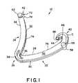
- FIG. 1is an enlarged perspective view of the surgical ligating clip of the present invention
- FIG. 2is another enlarged perspective view of the surgical ligating clip of the present invention
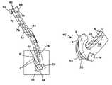
- FIG. 3is an enlarged fragmentary view of the hook member leg of the surgical ligating clip of the present invention.
- FIG. 4is a top plan view of the hook member of the surgical ligating clip of the present invention.
- FIG. 5is a side elevation view of the surgical ligating clip of the present invention.
- FIG. 6is a side elevation view of the hook member of the surgical ligating clip of the present invention.
- FIG. 7Ais a perspective view of a clip applier being inserted into a compartment of a clip cartridge to engage a surgical ligating clip provided in accordance with the present invention
- FIG. 7Bis another perspective view showing the clip applier engaging the surgical ligating clip loaded in one of the compartments of the clip cartridge as shown in FIG. 7 A.
- FIG. 7Cis another perspective view showing the clip applier extracting the surgical ligating clip from the compartment of the clip cartridge shown in FIG. 7 A.
- clip 12is suitable for use in conjunction with the present invention.
- Clip 12 and others of similar designare particularly useful as hemostatic clips that can be latched around a vessel or other type of tissue to ligate the vessel and thereby stop or reduce the flow of fluid through the vessel.
- Clip 12can be constructed from any suitable biocompatible material, such as certain metals and polymers.
- the present inventionis particularly suitable for practice with polymeric clips.
- clip 12preferably comprises a one-piece integral polymeric body formed from a suitable strong biocompatible engineering plastic such as the type commonly used for surgical implants. Examples include polyethylene terephthalate (PET), polybutylene terephthalate (PBT), polyoxymethylene, or other thermoplastic materials having similar properties that can be injection-molded, extruded or otherwise processed into like articles.
- PETpolyethylene terephthalate
- PBTpolybutylene terephthalate
- polyoxymethyleneor other thermoplastic materials having similar properties that can be injection-molded, extruded or otherwise processed into like articles.
- the body of clip 12comprises a first or outer leg, generally designated 22 , and a second or inner leg, generally designated 24 .
- First and second legs 22 and 24are joined at their proximal ends by an integral hinge section, generally designated 26 .
- First and second legs 22 and 24have complementary arcuate profiles.
- first leg 22has a concave inner surface 28 and a convex outer surface 30
- second leg 24has a convex inner surface 32 and a concave outer surface 34
- Convex inner surface 32 of second leg 24 and concave inner surface 28 of first leg 22have substantially matching radii of curvature.
- Hinge section 26has a continuous concave inner surface 36 and a continuous convex outer surface 38 .
- Concave inner surface 36 of hinge section 26joins concave inner surface 28 of first leg 22 and convex inner surface 32 of second leg 24 .
- Convex outer surface 38 of hinge section 26joins convex outer surface 30 of first leg 22 and concave outer surface 34 of second leg 24 .
- First leg 22transitions to a curved, C-shaped hook section 40 at its distal end.
- Second leg 24transitions to a pointed tip section 42 at its distal end.
- Hook section 40is distally reversely curved inwardly, and has a transverse beveled surface 44 .
- Beveled surface 44 and concave inner surface 28define a latching recess 46 , which is adapted for conformally engaging tip section 42 in the course of compressing clip 12 into a latched or locked position around a vessel or other tissue.
- the top surface of C-shaped hook section 40(see FIG. 4 ) comprises two convex surfaces C that come together to define a sharp crest-like cutting edge E to facilitate cutting through connective tissue adjacent a vessel or other tissue during latching of the clip therearound in a manner to be described in greater detail hereinbelow.
- clip 12comprises parallel, opposed side surfaces 52 and 54 .
- the body of clip 12has a constant thickness between side surfaces 52 and 54 .
- a pair of cylindrical bosses 56 and 58are formed coaxially on the opposed lateral surfaces of first leg 22 .
- a bridge section 66couples bosses 56 and 58 together.
- bosses 56 and 58project outwardly beyond convex outer surface 30 of first leg 22 .
- bosses 62 and 64are formed coaxially on the opposed lateral surfaces of inner leg 24 at tip section 42 . As evident in FIG. 1 , bosses 62 and 64 of second leg 24 extend longitudinally forwardly beyond tip section 42 .
- hook section 40 of first leg 22terminates at a sharp tip 68 with cutting edge E extending at least along a portion of the length of the top surface of hook section 40
- the distal end of second leg 24includes a pair of sharp tissue-penetrating teeth 72 and 74
- both first and second legs 22 and 24have a plurality of protrusions or teeth 76 extending from their respective inner surfaces 28 and 32 .
- clip 12is designed to be compressed into a latched or locked position around the vessel through the use of an appropriate clip applicator instrument, such as the type described in the aforementioned U.S. Pat. No. 5,100,416.
- the clip applicator instrumentengages bosses 56 , 58 , 62 and 64 of clip 12 and pivots bosses 56 , 58 , 62 and 64 inwardly about hinge section 26 .
- Thiscauses first and second legs 22 and 24 to close around the vessel, with convex inner surface 32 of second leg 24 and complementary concave inner surface 28 of first leg 22 contacting the outer wall of the vessel. Tip section 42 of second leg 24 then begins to contact hook section 40 .
- tip section 42Further pivotal movement by the applicator instrument longitudinally elongates first leg 22 and deflects hook section 40 , allowing tip section 42 to align with latching recess 46 .
- tip section 42Upon release of the applicator instrument, tip section 42 snaps into and is conformably seated in latching recess 46 , at which point clip 12 is in its latched condition. In the latched condition, tip section 42 is engaged between concave inner surface 28 and beveled surface 44 , thereby securely clamping a designated vessel or other tissue between concave inner surface 28 and convex inner surface 32 .
- Prior art clips similar to clip 12are described in detail in the commonly assigned U.S. Pat. No. 4,834,096 to Oh et al. and U.S. Pat. No. 5,062,846 to Oh et al., the disclosures of which are incorporated herein in their entireties.
- a particularly suitable clipis the HEM-O-LOK® clip commercially available from the assignee of the present invention. These clips are currently available in sizes designated “M”, “ML”, and “L”.
- the clip cartridge of the invention described hereinbelowcan be adapted to accommodate any sizes of HEM-O-LOK® clips commercially available.
- Clip cartridge 100preferably is constructed from a single-molded plastic body from which several features are formed.
- clip cartridge 100comprises a plurality of clip retaining chambers or compartments 111 spaced along a longitudinal axis L of clip cartridge 100 .
- Each clip compartment 111is substantially identical and adapted for storing one clip 12 , which preferably has an asymmetric design as described above and illustrated in FIGS. 1-6 .
- FIG. 7Aillustrates one clip 12 in a stored condition in one of clip compartments 111 .
- clip cartridge 100include several clip compartments 111 for storing several clips 12 .
- clip cartridge 100is adapted for storing six clips 12 , although other embodiments can be provided that store more or less clips 12 .
- an adhesive backing(not shown) can be provided on the underside of clip cartridge 100 to facilitate securing clip cartridge 100 to a tray or other supporting component during use.
- FIGS. 7A-7Calso illustrate the distal end of a representative clip applying instrument for clip 12 , generally designated 120 , comprising opposing pivotable jaws 125 A and 125 B. Jaws 125 A and 125 B have respective jaw recesses 127 A and 127 B adapted to engage and retain bosses 56 , 58 , 62 and 64 of clip 12 (see FIGS. 1 - 6 ).
- FIG. 7Aillustrates clip applying instrument 120 in a position over clip 12 prior to inserting clip applying instrument 120 into a selected clip compartment 111 .
- FIG. 7Billustrates clip applying instrument 120 being inserted into selected clip compartment 111 to load clip 12 into locking engagement with clip applying instrument 120 (with bosses 56 , 58 , 62 and 64 retained in jaw recesses 127 A and 127 B).
- FIG. 7Cillustrates the subsequent step of extracting clip 12 from clip cartridge 100 by removing clip applying instrument 120 with clip 12 loaded therein.
- the penetrating member of the hook on the end of the first legis moving through the groove between the penetrating members of the second leg and as penetrating members move closely alongside the sides of the hook portion of the leg, sheer forces contribute to puncturing of the tissue by the tips of the penetrating members of the second leg.
- the knife-like edges of the penetrating membershelp to tear the connective tissue as the second leg moves down. There is still little or no contact between the penetrating member of the first leg and the groove of the second leg.
- the tissue caught between the distal end of the second leg and the hook portionbegins to stretch. Tissue is jammed between three sharp edges which move in opposite directions.
- the tissueis not yet cut between the distal portion of the second leg member and the hook portion, it will be stretched and become thinner and more easily punctured by the sharp point of the distal portion of the hook portion as it passes through the groove and flat beveled surface of the second leg. This point is very sharp and cuts through remaining stretched tissue. In this final stage of cutting and stretching, if all the tissue is not cut, what remains will be quite thin and allow the prior art surgical clip to latch. Although this prior art penetrating surgical clip has been found to effective, the improved penetrating surgical clip 12 of the present invention has been found to be superior in design and function.
- the hook element 40 at the end of first leg 22 and the pointed tip section 42 at the end of second leg 24 of clip 12are adapted for being compressed into a latched or locked position around a vessel or other tissue.
- beveled surface 44 and concave inner surface 28define a latching recess 46 , which is adapted for conformally engaging tip section 42 of the second leg 24 in the course of compressing clip 12 into the latched or locked position around a vessel or other tissue.
- the stretching, puncturing, and cutting of connective tissue by the distal end of the first leg member and the second leg member as the surgical clip is latched or locked around a vessel or other tissueis somewhat similar to the aforementioned latching action described in the prior art penetrating surgical clip described hereinabove.
- two convex surfaces Cextend distally from the inner surface of hook member 40 and inwardly from the sides 52 , 54 of hook member 40 so as to define a crest or cutting edge E at the juncture thereof along the top portion of the hook member as best shown in FIG. 3 and FIG. 4 of the drawings.
- leading edge E of the protruding hook member 40is defined by the termination of two intersecting convex surfaces C.
- leading edge C of hook member 40contacts the connective tissue and as pressure is applied by closing surgical clip 12 , leading edge E slides along the connective tissue and slices into it as first leg member 22 comprising hook member 40 conforms during latching of the surgical clip.
- the two convex arching surfaces C which create leading edge E of hook member 40allow for maximum strength and sharpness in the integral hook member cutting edge E.
Landscapes
- Health & Medical Sciences (AREA)
- Surgery (AREA)
- Life Sciences & Earth Sciences (AREA)
- Heart & Thoracic Surgery (AREA)
- Nuclear Medicine, Radiotherapy & Molecular Imaging (AREA)
- Vascular Medicine (AREA)
- Engineering & Computer Science (AREA)
- Biomedical Technology (AREA)
- Reproductive Health (AREA)
- Medical Informatics (AREA)
- Molecular Biology (AREA)
- Animal Behavior & Ethology (AREA)
- General Health & Medical Sciences (AREA)
- Public Health (AREA)
- Veterinary Medicine (AREA)
- Surgical Instruments (AREA)
Abstract
Description
Claims (6)
Priority Applications (3)
| Application Number | Priority Date | Filing Date | Title |
|---|---|---|---|
| US10/251,182US6863675B2 (en) | 2002-09-20 | 2002-09-20 | Ligating clip with integral penetrating hook |
| AU2002349909AAU2002349909A1 (en) | 2002-09-20 | 2002-10-23 | Ligating clip with integral penetrating hook |
| PCT/US2002/034076WO2004026148A1 (en) | 2002-09-20 | 2002-10-23 | Ligating clip with integral penetrating hook |
Applications Claiming Priority (1)
| Application Number | Priority Date | Filing Date | Title |
|---|---|---|---|
| US10/251,182US6863675B2 (en) | 2002-09-20 | 2002-09-20 | Ligating clip with integral penetrating hook |
Publications (2)
| Publication Number | Publication Date |
|---|---|
| US20040059359A1 US20040059359A1 (en) | 2004-03-25 |
| US6863675B2true US6863675B2 (en) | 2005-03-08 |
Family
ID=31992672
Family Applications (1)
| Application Number | Title | Priority Date | Filing Date |
|---|---|---|---|
| US10/251,182Expired - LifetimeUS6863675B2 (en) | 2002-09-20 | 2002-09-20 | Ligating clip with integral penetrating hook |
Country Status (3)
| Country | Link |
|---|---|
| US (1) | US6863675B2 (en) |
| AU (1) | AU2002349909A1 (en) |
| WO (1) | WO2004026148A1 (en) |
Cited By (54)
| Publication number | Priority date | Publication date | Assignee | Title |
|---|---|---|---|---|
| US20050165422A1 (en)* | 2004-01-22 | 2005-07-28 | Pilling Weck Incorporated | Ligating clip with integral cutting guide |
| US20050165421A1 (en)* | 2004-01-22 | 2005-07-28 | Pilling Weck Incorporated | Ligating clip with integral interlocking latch mechanism |
| US20060217749A1 (en)* | 2005-03-24 | 2006-09-28 | Pilling Weck Incorporated | Reduced closure force ligating clip |
| US20070083218A1 (en)* | 2005-10-12 | 2007-04-12 | A Morris Steven | Coated ligating clip |
| US20070118161A1 (en)* | 2005-11-22 | 2007-05-24 | Kennedy Daniel L | Non-snag polymer ligating clip |
| US20070276417A1 (en)* | 2004-07-02 | 2007-11-29 | Mendes Jr Jose B | Laterally Curved Surgical Clip |
| US20120271317A1 (en)* | 2002-07-26 | 2012-10-25 | Robert Greenberg | Surgical Tool for Electrode Implantation |
| CN103356264A (en)* | 2013-08-02 | 2013-10-23 | 杭州铭众生物科技有限公司 | Ligation clip |
| USD748462S1 (en)* | 2014-08-11 | 2016-02-02 | Auxocell Laboratories, Inc. | Centrifuge clip |
| US9375218B2 (en) | 2006-05-03 | 2016-06-28 | Datascope Corp. | Systems and methods of tissue closure |
| US9445820B2 (en) | 2007-12-31 | 2016-09-20 | Teleflex Medical Incorporated | Ligation clip with flexible clamping feature |
| US9642627B2 (en)* | 2010-11-02 | 2017-05-09 | Covidien Lp | Self-centering clip and jaw |
| WO2017189540A1 (en) | 2016-04-28 | 2017-11-02 | Grena Usa Llc | Polymeric ligating clip |
| US9855053B2 (en) | 2011-10-20 | 2018-01-02 | Teleflex Life Sciences Unlimited Copmany | Ligation clip |
| USD808522S1 (en)* | 2017-07-11 | 2018-01-23 | Vesolock Medical, Llc | Latching ends of a polymer ligating clip |
| US9993748B2 (en) | 2014-08-11 | 2018-06-12 | Auxocell Laboratories, Inc. | Centrifuge clip and method |
| US10136898B2 (en) | 2010-03-09 | 2018-11-27 | Teleflex Medical Incorporated | Narrow profile surgical ligation clip |
| USD838847S1 (en)* | 2017-10-20 | 2019-01-22 | Dahong Zhang | Hemostatic clamp |
| US10307166B2 (en) | 2011-09-15 | 2019-06-04 | Teleflex Medical Incorporated | Manual surgical ligation clip applier |
| US10485545B2 (en) | 2013-11-19 | 2019-11-26 | Datascope Corp. | Fastener applicator with interlock |
| US10548609B2 (en) | 2016-08-03 | 2020-02-04 | Teleflex Medical Incorporated | Surgical ligation clip |
| USD907204S1 (en) | 2019-08-02 | 2021-01-05 | Covidien Lp | Ligation clip |
| USD907203S1 (en) | 2019-08-02 | 2021-01-05 | Covidien Lp | Ligation clip |
| USD907200S1 (en) | 2019-08-05 | 2021-01-05 | Covidien Lp | Ligation clip |
| US10932788B2 (en) | 2018-04-11 | 2021-03-02 | Covidien Lp | Ligation clip with latching and retention features |
| US10932789B2 (en) | 2018-04-11 | 2021-03-02 | Covidien Lp | Ligation clip with latching and retention features |
| US10945740B2 (en) | 2017-06-22 | 2021-03-16 | Teleflex Medical Incorporated | Surgical clip |
| US20210128159A1 (en)* | 2018-07-18 | 2021-05-06 | Teleflex Medical Incorporated | Clip applier and cartridge |
| US11033279B2 (en)* | 2018-04-24 | 2021-06-15 | Covidien Lp | Ligation clip with retention features |
| USD934669S1 (en)* | 2020-03-19 | 2021-11-02 | Helmut Franz Wilhelm Lehle | Clip |
| US11179161B1 (en) | 2020-07-08 | 2021-11-23 | A2 Medical Systems LLC | Ligation clips with anti-migration features |
| US11246600B1 (en)* | 2020-08-13 | 2022-02-15 | Geoff Brown | Surgical ligation clip with advanced incising means and bifurcated guide track |
| US11266408B2 (en) | 2017-03-21 | 2022-03-08 | Teleflex Medical Incorporated | Clip applier having stabilizing member |
| US11304703B2 (en) | 2018-05-25 | 2022-04-19 | Covidien Lp | Ligation clip removal device |
| US11304704B2 (en) | 2018-08-22 | 2022-04-19 | Covidien Lp | Surgical clip applier and ligation clips |
| US11317923B2 (en) | 2018-08-13 | 2022-05-03 | Covidien Lp | Ligation clip with improved hinge |
| US11395660B2 (en) | 2019-08-05 | 2022-07-26 | Covidien Lp | Stackable ligation clip |
| US11471165B2 (en) | 2019-05-08 | 2022-10-18 | Covidien Lp | Ligation clip cartridge |
| US11534177B2 (en) | 2017-03-21 | 2022-12-27 | Teleflex Medical Incorporated | Flexible stabilizing member for a clip applier |
| US11607227B2 (en) | 2017-03-21 | 2023-03-21 | Teleflex Medical Incorporated | Surgical clip and clip applier |
| US11648014B2 (en) | 2017-11-14 | 2023-05-16 | Teleflex Medical Incorporated | Surgical clip |
| US11653928B2 (en) | 2018-03-28 | 2023-05-23 | Datascope Corp. | Device for atrial appendage exclusion |
| US11696764B2 (en) | 2020-01-31 | 2023-07-11 | Covidien Lp | Ligation clip with controlled tissue compression |
| US11707282B2 (en) | 2019-07-02 | 2023-07-25 | Covidien Lp | Multi-piece ligation clip |
| USD993411S1 (en) | 2017-11-03 | 2023-07-25 | Covidien Lp | Ligation clip with controlled tissue compression |
| US11744595B2 (en) | 2020-05-11 | 2023-09-05 | Grena Usa Llc | Ligating clip |
| US11992222B2 (en) | 2019-12-19 | 2024-05-28 | Teleflex Medical Incorporated | Surgical clip |
| US12023041B2 (en) | 2017-03-21 | 2024-07-02 | Teleflex Medical Incorporated | Clip applier |
| US12102334B2 (en) | 2017-03-21 | 2024-10-01 | Teleflex Medical Incorporated | Clip applier with stabilizing member |
| US12114866B2 (en) | 2020-03-26 | 2024-10-15 | Covidien Lp | Interoperative clip loading device |
| US12193673B2 (en) | 2020-06-05 | 2025-01-14 | Dravid Koura | Clip dispenser and method for dispensing and applying clips to tissue |
| US12279774B2 (en) | 2018-09-26 | 2025-04-22 | Teleflex Medical Incorporated | Clip applier with stabilizing member |
| US12318094B2 (en) | 2019-09-26 | 2025-06-03 | Teleflex Medical Incorporated | Clip applier |
| US12383244B2 (en) | 2021-11-30 | 2025-08-12 | Vhmed (Nantong) Co. Ltd. | Specimen retrieval bag, specimen retrieval device and method for using specimen retrieval device |
Families Citing this family (11)
| Publication number | Priority date | Publication date | Assignee | Title |
|---|---|---|---|---|
| WO2007093198A1 (en)* | 2006-02-15 | 2007-08-23 | Ethicon Endo-Surgery, Inc. | A device, clip, endoscope and method for the intraluminal treatment of tissue, e.g. hemorrhoids |
| US9084596B2 (en)* | 2012-02-27 | 2015-07-21 | Cook Medical Technologies Llc | Suture clamp and gastrointestinal suture anchor set device using same |
| US9220507B1 (en)* | 2012-10-14 | 2015-12-29 | Manoj B. Patel | Tissue spreading vascular clips with locking mechanism and non-slip clamping surfaces |
| KR101377429B1 (en) | 2013-02-20 | 2014-03-26 | (주)유원메디텍 | A ligating clip for surgical operation |
| CN103356263B (en)* | 2013-08-02 | 2015-02-18 | 杭州铭众生物科技有限公司 | Ligation clip |
| US10383637B2 (en) | 2015-07-30 | 2019-08-20 | Teleflex Medical Incorporated | Snap-on surgical clip cartridge |
| CN105078536A (en)* | 2015-08-26 | 2015-11-25 | 施青青 | Duplex tissue clip and clip applier |
| CN107981908B (en)* | 2017-12-29 | 2024-04-16 | 广东弘和医疗器械制造有限公司 | Anti-offset tissue clamp |
| CN108852453B (en)* | 2018-08-29 | 2019-12-10 | 华南理工大学 | A device for vascular ligation |
| CN109998626B (en)* | 2019-04-23 | 2024-06-21 | 陆晶 | Hemostatic clip for endoscope |
| CN110464411B (en)* | 2019-08-09 | 2024-04-12 | 伟格尔(广州)医疗设备有限公司 | Disposable tissue closing clamp supporting device |
Citations (13)
| Publication number | Priority date | Publication date | Assignee | Title |
|---|---|---|---|---|
| US3270745A (en) | 1963-06-11 | 1966-09-06 | Rene G Le Vaux | Hemostatic clip constructions |
| US3326216A (en) | 1964-03-30 | 1967-06-20 | Peter B Samuels | Hemostatic clip constructions |
| US3363628A (en) | 1964-09-28 | 1968-01-16 | Peter B Samuels | Hemostatic clip |
| US3439522A (en) | 1967-05-17 | 1969-04-22 | Peter B Samuels | Hemostatic clip and applicator |
| US3439523A (en) | 1964-03-30 | 1969-04-22 | Peter B Samuels | Hemostatic clip constructions |
| US4294355A (en) | 1979-12-06 | 1981-10-13 | Ethicon, Inc. | Cartridge for hemostatic clips |
| US4509518A (en) | 1982-02-17 | 1985-04-09 | United States Surgical Corporation | Apparatus for applying surgical clips |
| US4579118A (en) | 1983-06-01 | 1986-04-01 | Ethicon, Inc. | Hemostatic clip with penetration means |
| US4834096A (en) | 1987-10-26 | 1989-05-30 | Edward Weck Incorporated | Plastic ligating clips |
| US5062846A (en) | 1989-03-28 | 1991-11-05 | Edward Weck Incorporated | Penetrating plastic ligating clip |
| US5100416A (en) | 1989-10-17 | 1992-03-31 | Edward Weck Incorporated | Ligating clip applying instrument |
| US5509920A (en) | 1993-04-16 | 1996-04-23 | United States Surgical Corporation | Surgical hemostatic clip |
| US6391035B1 (en) | 2000-03-24 | 2002-05-21 | Timothy Appleby | Hemostatic clip removal instrument |
- 2002
- 2002-09-20USUS10/251,182patent/US6863675B2/ennot_activeExpired - Lifetime
- 2002-10-23AUAU2002349909Apatent/AU2002349909A1/ennot_activeAbandoned
- 2002-10-23WOPCT/US2002/034076patent/WO2004026148A1/ennot_activeApplication Discontinuation
Patent Citations (13)
| Publication number | Priority date | Publication date | Assignee | Title |
|---|---|---|---|---|
| US3270745A (en) | 1963-06-11 | 1966-09-06 | Rene G Le Vaux | Hemostatic clip constructions |
| US3326216A (en) | 1964-03-30 | 1967-06-20 | Peter B Samuels | Hemostatic clip constructions |
| US3439523A (en) | 1964-03-30 | 1969-04-22 | Peter B Samuels | Hemostatic clip constructions |
| US3363628A (en) | 1964-09-28 | 1968-01-16 | Peter B Samuels | Hemostatic clip |
| US3439522A (en) | 1967-05-17 | 1969-04-22 | Peter B Samuels | Hemostatic clip and applicator |
| US4294355A (en) | 1979-12-06 | 1981-10-13 | Ethicon, Inc. | Cartridge for hemostatic clips |
| US4509518A (en) | 1982-02-17 | 1985-04-09 | United States Surgical Corporation | Apparatus for applying surgical clips |
| US4579118A (en) | 1983-06-01 | 1986-04-01 | Ethicon, Inc. | Hemostatic clip with penetration means |
| US4834096A (en) | 1987-10-26 | 1989-05-30 | Edward Weck Incorporated | Plastic ligating clips |
| US5062846A (en) | 1989-03-28 | 1991-11-05 | Edward Weck Incorporated | Penetrating plastic ligating clip |
| US5100416A (en) | 1989-10-17 | 1992-03-31 | Edward Weck Incorporated | Ligating clip applying instrument |
| US5509920A (en) | 1993-04-16 | 1996-04-23 | United States Surgical Corporation | Surgical hemostatic clip |
| US6391035B1 (en) | 2000-03-24 | 2002-05-21 | Timothy Appleby | Hemostatic clip removal instrument |
Cited By (77)
| Publication number | Priority date | Publication date | Assignee | Title |
|---|---|---|---|---|
| US20120271317A1 (en)* | 2002-07-26 | 2012-10-25 | Robert Greenberg | Surgical Tool for Electrode Implantation |
| US20050165422A1 (en)* | 2004-01-22 | 2005-07-28 | Pilling Weck Incorporated | Ligating clip with integral cutting guide |
| US20050165421A1 (en)* | 2004-01-22 | 2005-07-28 | Pilling Weck Incorporated | Ligating clip with integral interlocking latch mechanism |
| US7326223B2 (en)* | 2004-01-22 | 2008-02-05 | Teleflex Medical Incorporated | Ligating clip with integral cutting guide |
| US7316696B2 (en)* | 2004-01-22 | 2008-01-08 | Teleflex Medical Incorporated | Ligating clip with integral interlocking latch mechanism |
| US20070276417A1 (en)* | 2004-07-02 | 2007-11-29 | Mendes Jr Jose B | Laterally Curved Surgical Clip |
| US20060217749A1 (en)* | 2005-03-24 | 2006-09-28 | Pilling Weck Incorporated | Reduced closure force ligating clip |
| US20070083218A1 (en)* | 2005-10-12 | 2007-04-12 | A Morris Steven | Coated ligating clip |
| WO2007062141A3 (en)* | 2005-11-22 | 2007-09-20 | Pilling Weck Inc | Non-snag polymer ligating clip |
| WO2007062141A2 (en) | 2005-11-22 | 2007-05-31 | Teleflex Medical Incorporated | Non-snag polymer ligating clip |
| US20070118161A1 (en)* | 2005-11-22 | 2007-05-24 | Kennedy Daniel L | Non-snag polymer ligating clip |
| US20090088783A1 (en)* | 2005-11-22 | 2009-04-02 | Kennedy Daniel L | Non-snag polymer ligating clip |
| EP1951128A4 (en)* | 2005-11-22 | 2010-05-05 | Teleflex Medical Inc | Non-snag polymer ligating clip |
| US11992211B2 (en) | 2006-05-03 | 2024-05-28 | Datascope Corp. | Systems and methods of tissue closure |
| US9375218B2 (en) | 2006-05-03 | 2016-06-28 | Datascope Corp. | Systems and methods of tissue closure |
| US11369374B2 (en) | 2006-05-03 | 2022-06-28 | Datascope Corp. | Systems and methods of tissue closure |
| US10595861B2 (en) | 2006-05-03 | 2020-03-24 | Datascope Corp. | Systems and methods of tissue closure |
| US9445820B2 (en) | 2007-12-31 | 2016-09-20 | Teleflex Medical Incorporated | Ligation clip with flexible clamping feature |
| US12193679B2 (en) | 2007-12-31 | 2025-01-14 | Teleflex Medical Incorporated | Ligation clip with flexible clamping feature |
| US10542998B2 (en) | 2007-12-31 | 2020-01-28 | Teleflex Medical Incorporated | Ligation clip with flexible clamping feature |
| US10136898B2 (en) | 2010-03-09 | 2018-11-27 | Teleflex Medical Incorporated | Narrow profile surgical ligation clip |
| US9642627B2 (en)* | 2010-11-02 | 2017-05-09 | Covidien Lp | Self-centering clip and jaw |
| US10307166B2 (en) | 2011-09-15 | 2019-06-04 | Teleflex Medical Incorporated | Manual surgical ligation clip applier |
| US9855053B2 (en) | 2011-10-20 | 2018-01-02 | Teleflex Life Sciences Unlimited Copmany | Ligation clip |
| US10820909B2 (en) | 2011-10-20 | 2020-11-03 | Teleflex Life Sciences Pte. Ltd. | Ligation clip |
| CN103356264A (en)* | 2013-08-02 | 2013-10-23 | 杭州铭众生物科技有限公司 | Ligation clip |
| US12396729B2 (en) | 2013-11-19 | 2025-08-26 | Datascope Corporation | Fastener applicator with interlock |
| US10485545B2 (en) | 2013-11-19 | 2019-11-26 | Datascope Corp. | Fastener applicator with interlock |
| US11564689B2 (en) | 2013-11-19 | 2023-01-31 | Datascope Corp. | Fastener applicator with interlock |
| USD748462S1 (en)* | 2014-08-11 | 2016-02-02 | Auxocell Laboratories, Inc. | Centrifuge clip |
| US9993748B2 (en) | 2014-08-11 | 2018-06-12 | Auxocell Laboratories, Inc. | Centrifuge clip and method |
| US10441901B2 (en) | 2014-08-11 | 2019-10-15 | Auxocell Laboratories, Inc. | Centrifuge clip and method |
| US10265079B2 (en) | 2016-04-28 | 2019-04-23 | Grena Usa Llc | Polymeric ligating clip |
| WO2017189540A1 (en) | 2016-04-28 | 2017-11-02 | Grena Usa Llc | Polymeric ligating clip |
| US11576680B2 (en) | 2016-08-03 | 2023-02-14 | Teleflex Medical Incorporated | Surgical ligation clip |
| US10548609B2 (en) | 2016-08-03 | 2020-02-04 | Teleflex Medical Incorporated | Surgical ligation clip |
| US11534177B2 (en) | 2017-03-21 | 2022-12-27 | Teleflex Medical Incorporated | Flexible stabilizing member for a clip applier |
| US11607227B2 (en) | 2017-03-21 | 2023-03-21 | Teleflex Medical Incorporated | Surgical clip and clip applier |
| US12433603B2 (en) | 2017-03-21 | 2025-10-07 | Teleflex Medical Incorporated | Flexible stabilizing member for a clip applier |
| US12102334B2 (en) | 2017-03-21 | 2024-10-01 | Teleflex Medical Incorporated | Clip applier with stabilizing member |
| US12064115B2 (en) | 2017-03-21 | 2024-08-20 | Teleflex Medical Incorporated | Clip applier having stabilizing member |
| US12023041B2 (en) | 2017-03-21 | 2024-07-02 | Teleflex Medical Incorporated | Clip applier |
| US11266408B2 (en) | 2017-03-21 | 2022-03-08 | Teleflex Medical Incorporated | Clip applier having stabilizing member |
| US10945740B2 (en) | 2017-06-22 | 2021-03-16 | Teleflex Medical Incorporated | Surgical clip |
| US11911043B2 (en) | 2017-06-22 | 2024-02-27 | Teleflex Medical Incorporated | Surgical clip |
| USD808522S1 (en)* | 2017-07-11 | 2018-01-23 | Vesolock Medical, Llc | Latching ends of a polymer ligating clip |
| USD838847S1 (en)* | 2017-10-20 | 2019-01-22 | Dahong Zhang | Hemostatic clamp |
| USD993411S1 (en) | 2017-11-03 | 2023-07-25 | Covidien Lp | Ligation clip with controlled tissue compression |
| US12426889B2 (en) | 2017-11-14 | 2025-09-30 | Teleflex Medical Incorporated | Surgical clip |
| US11648014B2 (en) | 2017-11-14 | 2023-05-16 | Teleflex Medical Incorporated | Surgical clip |
| US11998215B2 (en) | 2017-11-14 | 2024-06-04 | Teleflex Medical Incorporated | Surgical clip |
| US11653928B2 (en) | 2018-03-28 | 2023-05-23 | Datascope Corp. | Device for atrial appendage exclusion |
| US10932789B2 (en) | 2018-04-11 | 2021-03-02 | Covidien Lp | Ligation clip with latching and retention features |
| US10932788B2 (en) | 2018-04-11 | 2021-03-02 | Covidien Lp | Ligation clip with latching and retention features |
| US11033279B2 (en)* | 2018-04-24 | 2021-06-15 | Covidien Lp | Ligation clip with retention features |
| US11304703B2 (en) | 2018-05-25 | 2022-04-19 | Covidien Lp | Ligation clip removal device |
| US20210128159A1 (en)* | 2018-07-18 | 2021-05-06 | Teleflex Medical Incorporated | Clip applier and cartridge |
| US11317923B2 (en) | 2018-08-13 | 2022-05-03 | Covidien Lp | Ligation clip with improved hinge |
| US11304704B2 (en) | 2018-08-22 | 2022-04-19 | Covidien Lp | Surgical clip applier and ligation clips |
| US12279774B2 (en) | 2018-09-26 | 2025-04-22 | Teleflex Medical Incorporated | Clip applier with stabilizing member |
| US11471165B2 (en) | 2019-05-08 | 2022-10-18 | Covidien Lp | Ligation clip cartridge |
| US11707282B2 (en) | 2019-07-02 | 2023-07-25 | Covidien Lp | Multi-piece ligation clip |
| US12285176B2 (en) | 2019-07-02 | 2025-04-29 | Covidien Lp | Multi-piece ligation clip |
| USD907204S1 (en) | 2019-08-02 | 2021-01-05 | Covidien Lp | Ligation clip |
| USD907203S1 (en) | 2019-08-02 | 2021-01-05 | Covidien Lp | Ligation clip |
| USD907200S1 (en) | 2019-08-05 | 2021-01-05 | Covidien Lp | Ligation clip |
| US11395660B2 (en) | 2019-08-05 | 2022-07-26 | Covidien Lp | Stackable ligation clip |
| US12318094B2 (en) | 2019-09-26 | 2025-06-03 | Teleflex Medical Incorporated | Clip applier |
| US11992222B2 (en) | 2019-12-19 | 2024-05-28 | Teleflex Medical Incorporated | Surgical clip |
| US11696764B2 (en) | 2020-01-31 | 2023-07-11 | Covidien Lp | Ligation clip with controlled tissue compression |
| USD934669S1 (en)* | 2020-03-19 | 2021-11-02 | Helmut Franz Wilhelm Lehle | Clip |
| US12114866B2 (en) | 2020-03-26 | 2024-10-15 | Covidien Lp | Interoperative clip loading device |
| US11744595B2 (en) | 2020-05-11 | 2023-09-05 | Grena Usa Llc | Ligating clip |
| US12193673B2 (en) | 2020-06-05 | 2025-01-14 | Dravid Koura | Clip dispenser and method for dispensing and applying clips to tissue |
| US11179161B1 (en) | 2020-07-08 | 2021-11-23 | A2 Medical Systems LLC | Ligation clips with anti-migration features |
| US11246600B1 (en)* | 2020-08-13 | 2022-02-15 | Geoff Brown | Surgical ligation clip with advanced incising means and bifurcated guide track |
| US12383244B2 (en) | 2021-11-30 | 2025-08-12 | Vhmed (Nantong) Co. Ltd. | Specimen retrieval bag, specimen retrieval device and method for using specimen retrieval device |
Also Published As
| Publication number | Publication date |
|---|---|
| WO2004026148A1 (en) | 2004-04-01 |
| US20040059359A1 (en) | 2004-03-25 |
| AU2002349909A1 (en) | 2004-04-08 |
Similar Documents
| Publication | Publication Date | Title |
|---|---|---|
| US6863675B2 (en) | Ligating clip with integral penetrating hook | |
| US7326223B2 (en) | Ligating clip with integral cutting guide | |
| US7316696B2 (en) | Ligating clip with integral interlocking latch mechanism | |
| US20060217749A1 (en) | Reduced closure force ligating clip | |
| US12193679B2 (en) | Ligation clip with flexible clamping feature | |
| US20070118161A1 (en) | Non-snag polymer ligating clip | |
| US20050165423A1 (en) | Ligating clip with integral tissue-securing mechanism | |
| EP0423671B1 (en) | Penetrating plastic ligating clip | |
| US10335157B2 (en) | Asymmetrical surgical clip with penetrating lock, non-slip clamping surface, severable hinge, hinge boss and pivoting applicator tip | |
| CA2604216A1 (en) | Reduced closure force ligating clip | |
| US5100416A (en) | Ligating clip applying instrument | |
| HK1006801B (en) | Penetrating plastic ligating clip | |
| HK1094934B (en) | Ligating clip with integral cutting guide | |
| HK1097715B (en) | Ligating clip with integral interlocking latch mechanism |
Legal Events
| Date | Code | Title | Description |
|---|---|---|---|
| AS | Assignment | Owner name:WECK CLOSURE SYSTEMS, NORTH CAROLINA Free format text:ASSIGNMENT OF ASSIGNORS INTEREST;ASSIGNOR:WILSON, JR., DONALD F.;REEL/FRAME:013455/0375 Effective date:20020924 | |
| AS | Assignment | Owner name:PILLING WECK INCORPORATED, PENNSYLVANIA Free format text:ASSIGNMENT OF ASSIGNORS INTEREST;ASSIGNOR:WILSON, DONALD F.JR.;REEL/FRAME:014464/0084 Effective date:20020924 | |
| STCF | Information on status: patent grant | Free format text:PATENTED CASE | |
| AS | Assignment | Owner name:TECHNOLOGY HOLDING COMPANY II, DELAWARE Free format text:ASSIGNMENT OF ASSIGNORS INTEREST;ASSIGNOR:PILLING WECK INCORPORATED;REEL/FRAME:017353/0423 Effective date:20051212 | |
| CC | Certificate of correction | ||
| FPAY | Fee payment | Year of fee payment:4 | |
| REMI | Maintenance fee reminder mailed | ||
| FPAY | Fee payment | Year of fee payment:8 | |
| FPAY | Fee payment | Year of fee payment:12 | |
| AS | Assignment | Owner name:PILLING WECK INCORPORATED, PENNSYLVANIA Free format text:CERTIFICATE OF CANCELLATION;ASSIGNOR:WECK CLOSURE SYSTEMS, LLC;REEL/FRAME:041638/0422 Effective date:20030521 | |
| AS | Assignment | Owner name:JPMORGAN CHASE BANK, N.A., AS ADMINISTRATIVE AGENT Free format text:SECURITY INTEREST;ASSIGNOR:TECHNOLOGY HOLDING COMPANY II;REEL/FRAME:041760/0414 Effective date:20170217 | |
| RR | Request for reexamination filed | Effective date:20170926 | |
| CONR | Reexamination decision confirms claims | Kind code of ref document:C1 Free format text:REEXAMINATION CERTIFICATE Filing date:20170926 Effective date:20180409 | |
| AS | Assignment | Owner name:TECHNOLOGY HOLDING COMPANY II, DELAWARE Free format text:ASSIGNMENT OF ASSIGNORS INTEREST;ASSIGNOR:WECK CLOSURE SYSTEMS, LLC;REEL/FRAME:046800/0365 Effective date:20180809 | |
| AS | Assignment | Owner name:TELEFLEX MEDICAL INCORPORATED, PENNSYLVANIA Free format text:ASSIGNMENT OF ASSIGNORS INTEREST;ASSIGNOR:TECHNOLOGY HOLDING COMPANY II;REEL/FRAME:046645/0857 Effective date:20180810 | |
| IPR | Aia trial proceeding filed before the patent and appeal board: inter partes review | Free format text:TRIAL NO: IPR2019-00257 Opponent name:SYMMETRY SURGICAL INC. Effective date:20181109 | |
| AS | Assignment | Owner name:JPMORGAN CHASE BANK, N.A., AS ADMINISTRATIVE AGENT Free format text:SECURITY INTEREST;ASSIGNOR:TELEFLEX MEDICAL INCORPORATED;REEL/FRAME:050620/0904 Effective date:20190925 Owner name:JPMORGAN CHASE BANK, N.A., AS ADMINISTRATIVE AGENT, ILLINOIS Free format text:SECURITY INTEREST;ASSIGNOR:TELEFLEX MEDICAL INCORPORATED;REEL/FRAME:050620/0904 Effective date:20190925 |