US6862405B2 - Apparatus, method and system of liquid-based, wide range, fast response temperature control of electric devices - Google Patents
Apparatus, method and system of liquid-based, wide range, fast response temperature control of electric devicesDownload PDFInfo
- Publication number
- US6862405B2 US6862405B2US10/224,571US22457102AUS6862405B2US 6862405 B2US6862405 B2US 6862405B2US 22457102 AUS22457102 AUS 22457102AUS 6862405 B2US6862405 B2US 6862405B2
- Authority
- US
- United States
- Prior art keywords
- temperature
- semiconductor device
- set point
- degrees
- heater
- Prior art date
- Legal status (The legal status is an assumption and is not a legal conclusion. Google has not performed a legal analysis and makes no representation as to the accuracy of the status listed.)
- Expired - Lifetime, expires
Links
- 239000007788liquidSubstances0.000titleclaimsabstractdescription82
- 238000000034methodMethods0.000titleabstractdescription22
- 230000004044responseEffects0.000titleabstractdescription8
- 238000010438heat treatmentMethods0.000claimsabstractdescription16
- 239000004065semiconductorSubstances0.000claimsdescription30
- DFUYAWQUODQGFF-UHFFFAOYSA-N1-ethoxy-1,1,2,2,3,3,4,4,4-nonafluorobutaneChemical compoundCCOC(F)(F)C(F)(F)C(F)(F)C(F)(F)FDFUYAWQUODQGFF-UHFFFAOYSA-N0.000claimsdescription2
- SQEGLLMNIBLLNQ-UHFFFAOYSA-N1-ethoxy-1,1,2,3,3,3-hexafluoro-2-(trifluoromethyl)propaneChemical compoundCCOC(F)(F)C(F)(C(F)(F)F)C(F)(F)FSQEGLLMNIBLLNQ-UHFFFAOYSA-N0.000claimsdescription2
- 239000002826coolantSubstances0.000abstractdescription28
- 230000000694effectsEffects0.000abstractdescription7
- 238000012360testing methodMethods0.000description35
- OKKJLVBELUTLKV-UHFFFAOYSA-NMethanolChemical compoundOCOKKJLVBELUTLKV-UHFFFAOYSA-N0.000description33
- XLYOFNOQVPJJNP-UHFFFAOYSA-NwaterSubstancesOXLYOFNOQVPJJNP-UHFFFAOYSA-N0.000description14
- 239000000203mixtureSubstances0.000description9
- 238000013459approachMethods0.000description7
- 230000008859changeEffects0.000description6
- 230000006870functionEffects0.000description6
- 239000001307heliumSubstances0.000description6
- 229910052734heliumInorganic materials0.000description6
- SWQJXJOGLNCZEY-UHFFFAOYSA-Nhelium atomChemical compound[He]SWQJXJOGLNCZEY-UHFFFAOYSA-N0.000description6
- 230000001965increasing effectEffects0.000description6
- 230000008569processEffects0.000description6
- LYCAIKOWRPUZTN-UHFFFAOYSA-NEthylene glycolChemical compoundOCCOLYCAIKOWRPUZTN-UHFFFAOYSA-N0.000description5
- 238000001816coolingMethods0.000description5
- 238000010586diagramMethods0.000description5
- 238000009835boilingMethods0.000description4
- 230000003247decreasing effectEffects0.000description4
- 239000012530fluidSubstances0.000description4
- 239000007789gasSubstances0.000description4
- 238000002347injectionMethods0.000description4
- 239000007924injectionSubstances0.000description4
- 230000015556catabolic processEffects0.000description3
- 238000013461designMethods0.000description3
- 238000012544monitoring processMethods0.000description3
- 238000013021overheatingMethods0.000description3
- 238000012546transferMethods0.000description3
- 238000000576coating methodMethods0.000description2
- 238000004891communicationMethods0.000description2
- 238000004590computer programMethods0.000description2
- 230000006378damageEffects0.000description2
- 238000006731degradation reactionMethods0.000description2
- 230000009977dual effectEffects0.000description2
- 230000007613environmental effectEffects0.000description2
- 239000002360explosiveSubstances0.000description2
- 238000012423maintenanceMethods0.000description2
- 238000004519manufacturing processMethods0.000description2
- 239000000463materialSubstances0.000description2
- 238000012545processingMethods0.000description2
- 230000009467reductionEffects0.000description2
- 230000007704transitionEffects0.000description2
- 239000004593EpoxySubstances0.000description1
- 230000001133accelerationEffects0.000description1
- 239000000654additiveSubstances0.000description1
- 230000002528anti-freezeEffects0.000description1
- 230000000712assemblyEffects0.000description1
- 238000000429assemblyMethods0.000description1
- 230000008901benefitEffects0.000description1
- 238000004364calculation methodMethods0.000description1
- 230000003750conditioning effectEffects0.000description1
- 238000013480data collectionMethods0.000description1
- 230000001419dependent effectEffects0.000description1
- 238000005516engineering processMethods0.000description1
- 238000007710freezingMethods0.000description1
- 230000008014freezingEffects0.000description1
- 238000011990functional testingMethods0.000description1
- WGCNASOHLSPBMP-UHFFFAOYSA-NhydroxyacetaldehydeNatural productsOCC=OWGCNASOHLSPBMP-UHFFFAOYSA-N0.000description1
- 230000001939inductive effectEffects0.000description1
- 230000010365information processingEffects0.000description1
- 230000000977initiatory effectEffects0.000description1
- 230000007774longtermEffects0.000description1
- 230000013011matingEffects0.000description1
- 238000002844meltingMethods0.000description1
- 230000008018meltingEffects0.000description1
- 231100000252nontoxicToxicity0.000description1
- 230000003000nontoxic effectEffects0.000description1
- 230000003287optical effectEffects0.000description1
- 238000004806packaging method and processMethods0.000description1
- 238000009428plumbingMethods0.000description1
- 231100000614poisonToxicity0.000description1
- 230000007096poisonous effectEffects0.000description1
- 230000035945sensitivityEffects0.000description1
- 229910000679solderInorganic materials0.000description1
- 239000007787solidSubstances0.000description1
- 238000005507sprayingMethods0.000description1
- 239000000126substanceSubstances0.000description1
- 230000008646thermal stressEffects0.000description1
- 238000013519translationMethods0.000description1
- 238000009966trimmingMethods0.000description1
- 230000001755vocal effectEffects0.000description1
- 238000003466weldingMethods0.000description1
Images


Classifications
- G—PHYSICS
- G05—CONTROLLING; REGULATING
- G05D—SYSTEMS FOR CONTROLLING OR REGULATING NON-ELECTRIC VARIABLES
- G05D23/00—Control of temperature
- G—PHYSICS
- G01—MEASURING; TESTING
- G01R—MEASURING ELECTRIC VARIABLES; MEASURING MAGNETIC VARIABLES
- G01R31/00—Arrangements for testing electric properties; Arrangements for locating electric faults; Arrangements for electrical testing characterised by what is being tested not provided for elsewhere
- G01R31/28—Testing of electronic circuits, e.g. by signal tracer
- G01R31/2851—Testing of integrated circuits [IC]
- G01R31/2855—Environmental, reliability or burn-in testing
- G01R31/2872—Environmental, reliability or burn-in testing related to electrical or environmental aspects, e.g. temperature, humidity, vibration, nuclear radiation
- G01R31/2874—Environmental, reliability or burn-in testing related to electrical or environmental aspects, e.g. temperature, humidity, vibration, nuclear radiation related to temperature
- G—PHYSICS
- G01—MEASURING; TESTING
- G01R—MEASURING ELECTRIC VARIABLES; MEASURING MAGNETIC VARIABLES
- G01R31/00—Arrangements for testing electric properties; Arrangements for locating electric faults; Arrangements for electrical testing characterised by what is being tested not provided for elsewhere
- G01R31/28—Testing of electronic circuits, e.g. by signal tracer
- G01R31/2851—Testing of integrated circuits [IC]
- G01R31/2886—Features relating to contacting the IC under test, e.g. probe heads; chucks
- G01R31/2891—Features relating to contacting the IC under test, e.g. probe heads; chucks related to sensing or controlling of force, position, temperature
- G—PHYSICS
- G01—MEASURING; TESTING
- G01R—MEASURING ELECTRIC VARIABLES; MEASURING MAGNETIC VARIABLES
- G01R31/00—Arrangements for testing electric properties; Arrangements for locating electric faults; Arrangements for electrical testing characterised by what is being tested not provided for elsewhere
- G01R31/28—Testing of electronic circuits, e.g. by signal tracer
- G01R31/2801—Testing of printed circuits, backplanes, motherboards, hybrid circuits or carriers for multichip packages [MCP]
- G01R31/2806—Apparatus therefor, e.g. test stations, drivers, analysers, conveyors
- G—PHYSICS
- G01—MEASURING; TESTING
- G01R—MEASURING ELECTRIC VARIABLES; MEASURING MAGNETIC VARIABLES
- G01R31/00—Arrangements for testing electric properties; Arrangements for locating electric faults; Arrangements for electrical testing characterised by what is being tested not provided for elsewhere
- G01R31/28—Testing of electronic circuits, e.g. by signal tracer
- G01R31/2851—Testing of integrated circuits [IC]
- G01R31/2855—Environmental, reliability or burn-in testing
- G01R31/286—External aspects, e.g. related to chambers, contacting devices or handlers
- G01R31/2862—Chambers or ovens; Tanks
Definitions
- This inventionrelates to temperature control systems which maintain the temperature of an electronic device near a given set point temperature(s) while the device is being operated or tested.
- Two specific examples of electronic devices which need to be operated or tested at a constant temperatureare packaged integrated chips and unpackaged bare chips.
- Maintaining the chip temperature near a given set pointis not difficult if the power dissipation of the chip is constant or varies in a small range while operating or testing. In such cases, it is only necessary to couple the chip through a fixed thermal resistance to a thermal mass which is at a fixed temperature. But if the instantaneous power dissipation of the chip varies up and down in a wide range while operating or testing, then maintaining the chip temperature near a constant set point is very difficult.
- chipsare being debugged or tested, it is advantageous to evaluate their performance at a variety of temperatures, ranging from cold to hot. Combining the ability to force temperature across a wide temperature range, while accommodating the temperature changes associated with varying instantaneous power dissipation, is very challenging.
- Typical approaches to solve this probleminvolve forced air convection systems that extend well beyond the desired forcing temperature range at both the hot and cold ends. In this way, an attempt can be made to accelerate the chip's temperature conditioning by overcooling or overheating. As the nominal power density of the chips continue to increase, the ability of forced air convection systems to overcool reaches practical limits, causing increases in the temperature error between the desired and actual temperatures relative to set point.
- Another problemis that chips fabricated in the latest processes have an increased sensitivity to high temperatures. The potential for chip damage due to overheating adds risk to the use of the overheating approach. Increased time to set point is the result, with lost utilization of expensive test equipment and engineering personnel as an expense.
- Another approachis the use of dual liquid conduction systems, with one hot and one cold liquid.
- the proportion of the liquidsare mechanically metered to affect the desired forcing temperature.
- this approachrequires that the metering occur very close to the chip. This imposes mechanical packaging constraints which limit the flexibility to bring the surface of the temperature forcing system control surface into contact with the chip or chip package. Even so, the mechanical metering of the dual liquids is much slower to affect a change in the forcing temperature when compared to the temperature changes induced by the chip's instantaneous power dissipation. This also causes increased error between the desired and actual temperatures.
- the present inventionis directed to overcoming or at least reducing the effects of one or more of the problems set out above.
- This inventioncombines the optimal liquid and liquid temperature control system with a heat exchanger.
- a single liquidis used to cover as much of the temperature range as possible.
- Modes of the control of the heating elementare then used to extend the set point temperature range which the temperature forcing system contact surface can apply.
- the flow rate of the liquid through the heat exchangeris metered, to optimize the power dissipation of the heat exchanger, versus the desired thermal control performance at the chip.
- the present inventionprovides a liquid based, wide range, fast response chip temperature control system.
- the wide temperature rangeis achieved by extending the effective temperature range of a liquid based coolant loop with resistive heating in the control surface.
- the desired temperature range for testing chipscan be achieved, while supplying the features of: (i) fast set point temperature change, (ii) response to instantaneous power dissipation changes, and (iii) small form factor and flexibility in chip situations.
- This systemmay include: (i) the liquid cooling and recirculation system, (ii) the thermal control circuit which controls the heater temperature, (iii) the algorithms contained in the thermal control circuit which perform the translation from a desired device temperature to a heater control, and (iv) the heat exchanger consisting of a liquid cooled heat sink and a resistive heater bonded to it, which contacts the chip.
- an apparatus for controlling a temperature of a deviceincludes a heater, a heat sink and temperature control system.
- the temperature control systemis adapted to move the temperature of the point on the heater from approximately a first set point temperature to approximately a second set point temperature.
- an apparatus for controlling a temperature of a deviceincludes a heater, a heat sink, and a temperature control system.
- the temperature control systemis adapted to move the temperature of the point on the device from approximately a first set point temperature to approximately a second set point temperature.
- an apparatus for controlling a temperature of a deviceincludes a heater, a heat transfer unit, and a temperature control system.
- the temperature control systemis adapted to move the temperature of the point on the device by at least 50 degrees C. by controlling power sent to the heater and by controlling a temperature of a surface of the heat transfer unit.
- an apparatus for controlling a temperature of a deviceincludes a heater, a heat sink, and a temperature control system.
- the temperature control systemis coupled to both the heater and the heat sink and is adapted to maintain a temperature of a point on the device at or near a set point temperature despite the existence of self-heating of the device.
- an apparatus for controlling a temperature of a semiconductor device during testingincludes a heat exchanger and a temperature control system.
- the heat exchangeris adapted to be thermally coupled to the semiconductor device during testing.
- the temperature control systemis coupled to the heat exchanger and is for controlling the heat exchanger.
- the temperature control systemis adapted to maintain the temperature of the semiconductor device at or near a set point temperature during testing despite self-heating of the semiconductor device.
- the set point temperaturecan be set to a first value or to a second value which is at least 25 degrees Celsius lower.
- a method of controlling a temperature of a semiconductor device during testingincludes moving the temperature of the device to approximately a first set point temperature.
- the methodfurther includes moving the temperature of the device to approximately a second set point temperature.
- an apparatus for controlling a temperature of a semiconductor deviceincludes a heat exchanger, a gas injection fitting, and a temperature control system.
- the gas injection fittingis for injecting a gas into a contact region between the heat exchanger and the semiconductor device when the semiconductor device is contacting the heat exchanger.
- FIG. 1illustrates a general diagram of the system.
- FIG. 2illustrates a schematic for a liquid coolant system, according to one embodiment of the present invention.
- FIG. 3illustrates a high level schematic of the control electronics for one thermal control channel.
- FIG. 4illustrates a system changing the set point temperature of a test device, using the fast set point temperature change feature.
- FIG. 5shows an example profile setup screen.
- FIG. 6illustrates a three channel thermal control subsystem.
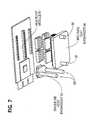
- FIG. 7depicts multiple heat exchangers on a multi-chip module.
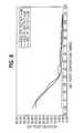
- FIG. 8contains a graph illustrating temperature control accuracy vs. set point.
- FIG. 9contains a graph showing junction temperature vs. set point-to-liquid delta T.
- FIG. 10depicts a heat exchanger with optional conductive coatings or structures.
- FIG. 11shows a socket assembly plumbed for helium injection.
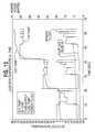
- FIG. 12contains a graph showing junction temperature vs. time.
- FIG. 13is a high-level block diagram showing an interrelationship between a test control system, a temperature control system, and a DUT.
- FIG. 1shows a general diagram of a system 10 according to the present invention.
- the useroperates the system 10 at the operator interface panel 12 .
- the operator interface panel 12serves as an interface to the system controller 14 .
- the system controller 14is housed in the system electronics enclosure 16 and controls the heat exchanger 20 and the liquid cooling and recirculation system 22 .
- the system electronics enclosure 16also contains the thermal control chassis 11 immediately under the system controller 14 .
- the two thin modules below the thermal control chassis 11are high voltage power supplies 13 , although one embodiment uses one large one instead of two small ones.
- the bottom moduleis the low voltage power supply 15 .
- the heat exchanger 20preferably includes a heater and a heat sink. Other heat exchangers are possible, however.
- the heat sinkpreferably contains a chamber through which the liquid is pumped. Other heat sinks are also possible. Heat sinks, or heat sink systems, with no liquid are also viable if the thermal conductivity is high enough.
- solid heat sinkssuch as Peltier devices are known in the art which use electrical signals through the material to control temperature and temperature gradients.
- a heat sinkmay also equivalently be referred to as a heat transfer unit, thus focusing attention on the fact that the heat sink may also act as a heat source.
- the heater of the preferred embodimentis a resistive heater.
- many other types of heaterscan also be used, including without limitation a heater utilizing lasers, other optics, or electromagnetic waves.
- a typical heater, or heat sinkwill have a temperature gradient across the surface.
- the existence of a gradientis due, in part, to the fact that the heating element usually occupies only a portion of the heater.
- the liquid cooling and recirculation system 22supplies a liquid to the heat exchanger 20 , specifically to the heat sink, through the boom arm 18 .
- the boom arm 18also carries the control signals from the system controller 14 and the thermal control chassis 11 to the heater.
- test head 21is adapted to be positioned under the heat exchanger 20 .
- the test head 21preferably contains a test socket which is used for mating with a device under test (“DUT”) such as a chip.
- DUTdevice under test
- FIG. 2shows a general schematic 23 for a coolant system which may be used with the present invention.
- the block diagram of a chiller system 22may be used for implementing the liquid cooling and recirculation system 22 of FIG. 1 .
- the chiller system 22pumps the liquid through a filter 26 , a flow control 28 , a flow sensor 30 , and finally to the heat exchanger 20 .
- the liquidthen returns to the chiller system 22 to be cooled and pumped back through the system.
- both the forward and return paths for the liquidgo through the boom arm 18 (of FIG. 1 ).
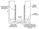
- FIG. 10shows, among other things, an embodiment in which a heat exchanger 20 is attached to a DUT 104 .
- the heat exchanger 20comprises a heater 112 , a heat sink 108 , heater power and heater RTD lines 102 , and liquid coolant lines 110 .
- the heater 112is flush against a surface of the heat sink 108 which is attached to a heat sink 108 .
- the liquid coolant lines 110supply liquid to the liquid heat sink 108 .
- the lines 102supply power to the heater 112 .
- the device 104whose temperature is to be controlled is disposed beneath and in contact with a bottom surface of the heater 112 .
- FIG. 10also shows optional conductive coatings and structures 106 which may be placed on the heater 112 to improve the thermal conductance to the chip 104 .
- This approachimproves the thermal conductance between the heater 112 and the chip 104 when compared to a trapped layer of air. Improving this thermal conductance then improves the chip temperature control performance. For a given power envelope of a DUT, the improved thermal conductance lowers a required temperature difference between a heat sink and a set point, as more fully explained later.
- the socket assemblies used to receive the chipare plumbed to allow for helium gas to be injected.
- Thisallows for helium to displace the air between the heater and the chip.
- Heliumis more thermally conductive than air, improving the thermal control performance.
- FIG. 11illustrates an embodiment of a socket assembly plumbed for Helium injection.
- the helium flowcan be controlled in a variety of ways known to one of ordinary skill in the art. One embodiment is for a control system to control the flow during actual testing of a device.
- FIG. 7illustrates an alternative embodiment in which multiple heat exchangers are utilized.
- heat exchanger 54 and heat exchanger 56have separate inlets and outlets 58 , 60 .
- Thisallows the two heat exchangers to be separately controlled and maintained at separate temperatures, if desired, using a single chiller (see FIG. 2 , element 22 ) and separate flow control for each heat exchanger (see FIG. 2 , elements 28 and 30 ).
- each sub-systemincludes separate heaters attached to the separate heat sinks in the manner illustrated in FIG. 10 . In such an embodiment, the heaters are each controlled separately.
- the separate inlets and outlets 58 , 60are connected to the same coolant system and the two heat exchangers 54 , 56 operated with liquid coolant which is at the same temperature in each heat exchanger. With separate heaters attached to the heat exchangers the separate dies may still be operated at different temperatures.
- a single coolant systemis used for multiple DUTs, such as a multi-chip module 61 , and the multi-die heat exchanger 56 is utilized.
- the multi-die heat exchanger 56can have separate heaters interposed between it and the respective DUTs of the multi-chip module 61 .
- a single coolant systemis used for multiple heat exchangers, and in-line heaters are installed in the coolant supply line (between elements 30 and 20 of FIG. 2 ) to raise the temperature of the coolant being supplied to one or more heat exchangers separately, to further increase the temperature control capability.
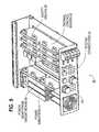
- FIG. 6illustrates an embodiment of a thermal control chassis 51 , capable of housing thermal control boards 52 for three control loops.
- FIG. 6contains a picture of a three channel thermal control sub-system 50 .
- the system 50includes a chassis 51 which includes three thermal control boards 52 , safety relays 59 (which are part of the self-test functionality in the electronics enclosure 16 and are used to test the integrity of the heater and RTD traces), three power monitoring circuit boards 55 , and three power amplifiers 57 .
- FIG. 6shows various other components, including system connectors 53 , which are standard for a chassis housing electronic equipment.
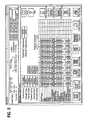
- FIG. 3shows a high level schematic 46 of the control electronics for a thermal control channel such as a thermal control board 52 of FIG. 6 .
- the schematic 46can be applied to the control of a heater in a heat exchanger 20 .
- the general operation of the schematic 46is described below, and details of this schematic for a particular embodiment can be found in an application by Jones which is discussed in a later section of this disclosure.
- the power monitoring circuit 34 of FIG. 3monitors the power used by a chip (not shown) and supplies an indication of that power to the thermal control board 36 .
- the thermal control circuit 38accepts this input.
- the thermal control circuit 38also accepts as an input the temperature of a forcing system, which is, for example, the temperature of the heater surface (not shown) which is in contact with the chip.
- the thermal control circuit 38then computes a thermal control signal which is sent to the heat exchanger temperature control 40 .
- the heat exchanger temperature control 40determines a heater power signal and sends it to a power amplifier 42 which in turn sends a heat exchanger power signal to the heat exchanger 20 .
- the thermal control board 36computes a signal that controls a heater, which is part of the heat exchanger 20 .
- the heat exchanger 20preferably includes a heat sink which contains a chamber through which a liquid is pumped.
- the liquid in the heat sinkmust: (i) have a low and relatively flat viscosity over the required temperature range so that it can be pumped; (ii) have a thermal capacity which is high enough over the required temperature range so that it can serve as an efficient heat exchange medium; (iii) be a safe chemical so that no injuries will result if any part of the human body is exposed to the liquid; and (iv) be a dielectric, meaning that the liquid will not electrically short any circuit onto which it might be spilled.
- the minimum temperature range for the first of these two characteristicsextends from approximately 40 or 60 degrees C. down to approximately ⁇ 40 degrees C.
- HFE7100a liquid (HFE7100) meets all of the above requirements.
- HFE7100is a specialty liquid manufactured by 3M corporation.
- HFE7100contains ethyl nonafluorobutylether and ethyl nonafluoroisobutylether.
- HFE7100is used at normal strength.
- HFE7100is non-toxic, non-explosive, non-conductive electrically, and is a safe liquid as compared to other alternatives.
- watercan be used with additives, such as methanol or ethylene glycol.
- additivessuch as methanol or ethylene glycol.
- such a mixtureis potentially explosive, poisonous, and has a high viscosity at low temperatures.
- it is difficult to maintain set points below roughly 60 degrees C. for devices which self-heatsee above discussion of FIG. 8 ).
- the HFE7100 liquidmeets the requirements for a minimum temperature range of from approximately ⁇ 40 degrees C. to approximately +40 or +60 degrees C. The liquid boils at roughly 60 degrees C.
- Other liquidswithout similar thermal, physical, environmental, and dielectric properties, are typically only operable in a more restricted range, for example at low temperatures or at high temperatures but not both. Therefore, a heat sink chamber would have to be drained and flushed and then filled with a different liquid mixture for operating at different temperatures.
- HFE7100can typically be used for set points, as differentiated from the liquid temperature, in an approximate range of ⁇ 10 to +110 degrees C. Further, the limits on the temperature range of HFE7100 can be extended in both directions with different chillers.
- HFE7100Other products, including new HFE products by 3M, which have similar thermal, physical, environmental, and dielectric properties, can serve as alternatives to HFE7100.
- Other alternativesmay exist or may be introduced into the market-place that allow the temperature range to be extended even further (similar heat capacity and viscosity at lower coolant temperatures to achieve lower setpoints, and/or a higher boiling point to achieve higher setpoints).
- One embodimentuses a chiller which is not pressurized and which can only bring the liquid down to ⁇ 40 degrees C.
- An alternate chillercould cool the liquid further and/or pressurize the liquid to allow it to be heated further as well.
- the current temperature range of the chilleris sufficient to achieve the desired set points when operated with a heater which can maintain a temperature differential of roughly 90 degrees C.
- One embodimentuses such a heater.
- a preferred chillercan bring the temperature of the liquid from ⁇ 40 degrees C. up to +40 degrees C. in about five minutes. This time increases as the amount of coolant increases and as the thermal mass of the coolant system and the plumbing increases. Thus, larger systems will take longer to move the temperature of the coolant.
- An embodimentuses a vacuum at the return side to produce a negative pressure coolant loop.
- Such an embodimenthas better leak tolerance in that it accumulates air in the system instead of spraying liquid from the system.
- the systemis built with quick disconnect capability, thus precluding the possibility of welding the system and virtually eliminating leaks.
- Embodimentsmay also use a slightly positive pressure to increase the flow rate. Such positive pressures, however, do not significantly affect the boiling point of the liquid.
- the preferred embodimentcontrols the temperature of a device 104 using a liquid-based heat sink 108 coupled to a heater 112 , as shown in FIG. 10 .
- the fluid, in the liquid coolant lines 110 , cooling the heat sink 108is typically kept at a roughly constant temperature below the set point while the heater 112 is used to bring the device temperature up to the set point.
- the coolant and the heater 112are operated at different temperatures.
- the heater 112is further used to effect quick changes in temperature control to accommodate and compensate for quick changes in the device 104 due to self-heating, for example. Many techniques can be used to accomplish the necessary active control of the heat exchanger 20 .
- the thermal control board 36performs a variety of functions. Generally speaking, a thermal control board must process input information related to the device temperature, and then determine how to adjust the heat exchanger to maintain the DUT at the desired set point. Such information can include without limitation the actual temperature of the DUT, the power consumed by the DUT, the current consumed by the DUT, the ‘predicted’ power of the DUT in a Feed Forward arrangement, or an indicator of the DUT temperature.
- a power profile, created for a particular devicecan also be used as an input which is related to the temperature of the particular device. The use of power profiles is described, for example, in the Pelissier and Jones applications mentioned earlier.
- Indicators of the temperaturecan be derived from a thermal structure such as, for example, thermal diodes or resistors in the DUT.
- the input information related to the device temperaturemay have information related to the absolute or relative position, velocity, and/or acceleration of the actual chip temperature.
- a thermal control boardmay be implemented in a variety of methods, including analog or digital circuitry as well as software. This applies both to the processing operations associated with accepting the inputs and making the necessary calculations, as well as to the control of the heat exchanger temperature.
- a variety of control techniquesmay also be used to achieve a controller with a desired combination of proportional, integral, and/or derivative control features.
- the control of the heateris the principal task of the temperature control system.
- the fluid in the heat sinkmust also be controlled by setting the temperature and the flow rate of the liquid. These settings, however, do not typically need to be changed during a test at a given set point and many different settings are possible.
- Typical applicationsoften use a flow rate of 0.5-2.5 liter/min, but this is largely a function of the heat exchanger design for the application.
- This range of flow ratesis often varied across the temperature range, with a higher flow rate being used with higher liquid temperatures and a lower flow rate being necessary for lower liquid temperatures due to the typically higher viscosity. It should also be clear that lower flow rates are one factor that can allow a higher delta T value. Where appropriate, this disclosure describes the settings used or the factors involved in selecting those settings.
- control requirementscan be sharply reduced in applications which do not require active control. Passive applications, where self-heating is not occurring or where it is not being actively offset, do not require that a temperature control system react as quickly. Burn-in is another example of an application which often does not need active temperature control, because the functional tests which are run often do not dissipate enough power to induce self-heating.
- a heat sinkis preferably kept at a relatively constant temperature below a set point temperature.
- the heat sinkpreferably has HFE7100, described earlier, flowing through a chamber.
- FIG. 8contains three curves which show the set point deviation as a function of set point temperature for three different systems.
- One systemuses a water/methanol mixture of 40% water and 60% methanol as the heat sink liquid and uses direct temperature following as the control method.
- a second systemalso uses the same water/methanol mixture, but uses power following as the control method.
- a third systemuses HFE7100 along with power following. The systems are attempting to control the temperature of a device under test.
- the DUThas a power usage which is rapidly changing between 0 and 25 watts/square cm.
- the curvesshow that the water/methanol mixture begins to have problems at set points around 60 degrees C. and gets progressively worse at lower temperatures.
- the poor performanceis encountered with both the direct temperature following and the power following control methods.
- the poor performancecan be explained in part by the difficulty in chilling the water/methanol mixture below 0 degrees C., the relatively poor viscosity of the freezing water/methanol mixture, and the low temperature difference that results between the chilled water/methanol mixture and the set point.
- the low temperature differencebecomes a problem, in part, because the system is unable to cool the DUT as quickly in response to self-heating, for example. This results in a greater deviation in the temperature of the DUT from the set point.
- HFE7100which maintains a set point deviation of less than approximately 4 or 5 degrees C. throughout the entire range of set point temperatures from ⁇ 10 degrees C. to +110 degrees C.
- the power dissipation through the heat exchanger heaterincreases with the set point-to-liquid temperature difference.
- Flow metering through the heat sinkis used to optimize the power dissipation whenever possible.
- Flow meteringcan also be used to reduce the load on the heat exchanger heater, enabling higher temperatures at lower power dissipations.
- the limit to the flow meteringis the heat-sink outlet temperature of the coolant, and any associated limits (e.g., exceeding the boiling point of the liquid at the system pressure). Decreasing the flow rate can allow a greater temperature between the liquid and the set point by decreasing the amount of heat that is drawn away from the heater.
- the heateris thus able to heat the DUT to a higher temperature.
- a particular embodimenthas a maximum flow rate of 4 liters/minute and a heater power of 300 watts.
- An embodiment of the present inventionalso enables a fast transition between different set points. Previous systems might require several hours to change between two different set points. The present invention enables this to be achieved in roughly 20-30 seconds between most set points. This reduction is due, in part, to the fact that the same equipment can be used for all set points of interest and the same liquid can be used in the heat sink chamber for all set points of interest. Further, the use of a heater along with a heat sink, and operating them at different temperatures, obviates the need for the heat sink liquid to move between the actual set points. This may offer an advantage if the liquid need only be moved over a smaller temperature range than the set point.
- embodiments of the present inventioncan also move between set point temperatures by changing only the temperature of the liquid and not using the heater to effect the transition. Given that the same liquid is used for both set point temperatures, the system can still achieve the new set point temperature in a reduced time, as described above in the discussion on chillers.
- control systemwill move the DUT temperature at the highest safe thermal expansion rate of the DUT and then clip the temperature at the set point.
- a linear, or trapezoidal, curve, with a slope indicative of a safe expansion rateis often desired in temperature profiles. This is as opposed, for instance, to an asymptotic approach to the desired temperature.
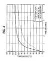
- FIG. 4contains two curves which show the temperature increase of two devices from approximately 20 degrees C. to at least 100 degrees C., for embodiments of the present invention.
- the flip chipmoved from an ambient temperature of 20 degrees C. to a set point of 100 degrees C. in roughly 1.5 seconds, and to a set point of 110 degrees C. in roughly 3.5 seconds.
- the wire bond with heat spreadermoved from an ambient temperature of 20 degrees C. to a set point of 100 degrees C. in roughly 4.5 seconds.
- FIG. 8illustrates the temperature control accuracy of an HFE7100 based system versus a water/methanol based system.
- the water/methanol systemhas an accuracy fall-off at cold due to increasing viscosity inducing decreasing flow rate through the heat exchanger.
- HFE7100has more consistent flow and viscosity across the liquid coolant temperature range. Although the HFE7100 will boil at approximately 60.degree. C., the higher set point temperatures are achievable with the higher set point-to-liquid temperature differences. That is, the heater can add the required heat.
- a higher temperature differencealso gives the heater more room to operate in either overshooting or undershooting the desired set point temperature. If the temperature difference between the heat sink and the heater is low, then the heater may “bottom out” if it is desired to sharply reduce the heater power. Such a reduction may be needed, for example, to offset self-heating of the device under test.
- FIG. 9illustrates that the junction temperature accuracy is as good or better with higher set point-to-liquid temperature differences. With larger temperature differences, the set point can be changed rapidly with little impact on the achievable temperature control performance.
- the “Delta T” curveis created from the individual data points indicating the Delta T used at different set point temperatures.
- the “Extreme Deviation from Set Point” curveis created from the individual data points indicating the maximum deviation that occurred at the different set points. As can be seen from FIG. 9 , as delta T is increased from approximately 30 degrees C., corresponding to a set point of approximately 30 degrees C., the deviation is relatively constant or decreasing. Much of the variation in the Delta T curve of FIG. 9 is caused by changes in the liquid temperature.
- FIG. 12also illustrates another example of maintaining the temperature of the device under test (“DUT”) at successively higher delta T's.
- delta Tis the difference between the “Fluid In T” line and the “Hx Temp.” line.
- the set points(not shown) are roughly 5, 30, and 70 degrees C.
- the “Power to DUT” curveshows that the DUT is drawing a variable amount of power and therefore experiencing fluctuating self-heating.
- the “HX Temp.” curveshows how the heater power, and therefore temperature, is controlled to maintain the “DUT Temp.” curve close to the desired set point.
- the “HX Temp.” curve, in conjunction with the “Fluid In T” curvealso show how the set point is moved twice, at roughly 22 seconds and 42 seconds, simply by changing the heater power and without changing the temperature of the liquid.
- the delta T rangeis variable based on several parameters. These parameters include the flow rate through a given heat sink design, the heat sink design itself, the maximum power level of the heater, the geometries of the heater and the DUT, and how much thermal load the DUT puts on the heater. In a typical application, 50 degree C. is a typical delta T value, but higher values are obtainable. Higher values can be obtained by adjusting the above, and other, parameters, such as by trimming down the coolant flow rate.
- the system controller 14executes software which interfaces to an operator via the operator interface terminal 12 .
- the softwareincludes the Windows NT operating system, Labview programming environment, and custom software developed to operate under Labview to perform the various functions of the system.
- a touch screenis used to simplify operation, but the keyboard/mouse interface is supported as well.
- a vocal inputcould also be used. It will be recognized that a variety of other software environments and user interfaces could be used.
- the softwareallows for “profiles” to be defined and stored.
- the profilesspecify the forcing temperature, rate of change to the new temperature and how the profile is advanced. Typically, this can be either time related, or advanced by signals from an external source, such as automatic test equipment used to test the chip.
- FIG. 5illustrates an example of the system software setup screens used to construct the profiles.
- the example profileindicates a sequence of nine set points for the DUT ranging from 70 degrees C. to 90 degrees C., allowable deviation of +/ ⁇ 2 degrees C., a temperature of 40 degrees C. for the liquid in the heat sink, a Delta T of 20 degrees C., and a thermal control mode of power following for each set point.
- the example profileincludes a variety of other fields related to soak time, PID control, data collection, and DUT temperature ramp control.
- the profilescan be programmed to cause the heater to overshoot or undershoot the desired set point in order to change the temperature of the DUT more quickly.
- the profilescan also be programmed to achieve the trapezoidal temperature curves described earlier.
- the set point deviationcan be characterized with a number of different methods.
- the set point deviationis specified as being no greater than 3 degrees C. for power densities no greater than 20 watts/cm.sup.2, and as being no greater than 5 degrees C. for power densities no greater than 30 watts/cm.sup.2. That is, the actual temperature will be within +/ ⁇ 3 degrees, or +/ ⁇ 5 degrees, of the set point temperature.
- the actual figuredepends on a variety of factors, including without limitation, whether the die is exposed or encased, the actual power density, and the thermal resistance of the die-heater boundary.
- the set point deviationis kept low enough such that results of a test of the DUT which determines f.sub.max at a set point temperature can be relied on as being accurate.
- the Jones applicationprovisional application Ser. No. 60/092,720 mentioned above has a more detailed discussion of fmax and its importance as a benchmark.
- an entire curveis determined by calculating f.sub.max at a variety of different temperature values.
- the set point deviationshould be kept sufficiently low at each of the different temperature values so that each is a reliable figure.
- a control systemmaintains the DUT temperature at a specified set point within a given tolerance.
- the control systemmust therefore have some information on the DUT temperature.
- the maintenance, or deviation control, processoften begins after the DUT has reached the set point temperature. This information may be determined indirectly, for example, after a soak timer has expired. It may also be determined directly, for example, by monitoring a thermal structure. Thermal structures can be used to supply initial DUT temperature information and they can also be monitored throughout the test if they are properly calibrated. One embodiment of the present invention monitors thermal structures to determine the initial DUT temperature before initiating a power following temperature control method.
- Embodiments of the present inventionmay include separate control sections to control the temperature and to control the test sequence.
- FIG. 13there is shown a generic high-level block diagram illustrating a test control system 130 and temperature control system 132 , both of which are connected to and communicate with a DUT 134 .
- This disclosurehas been primarily concerned with describing the temperature control system 132 .
- the test control system 130would operate the appropriate tests on the DUT 134 while the temperature control system 132 controlled the DUT temperature.
- control systems 130 , 132need to communicate or otherwise coordinate their activities.
- Either the temperature control system 132 or the test control system 130can monitor a thermal structure.
- the test control system 130monitors the thermal structure of the DUT 134 and sends a signal, such as a scaled voltage, to the temperature control system 132 indicating the DUT temperature.
- FIG. 13shows the communication path of such an embodiment with a dashed line between the test control system 130 and the temperature control system 132 .
- Embodiments of the control systems and their architecturemay vary considerably.
- the two control systems 130 , 132are separate and have no direct communication. Both control systems 130 , 132 monitor the DUT 134 to gain the necessary DUT temperature information in order to coordinate their activities.
- the two control systems 130 , 132are fully integrated.
- One present embodimentuses HFE7100 as the liquid coolant, operating in the temperature range of ⁇ 40.degree. C. to +40.degree. C.
- the temperature difference between the coolant supply and the chip set point temperatureranges between 5.degree. C. and 160.degree. C.
- the high temperatureis limited by long term reliability issues associated with rapid, large, repeated temperature variations and associated thermal stresses of the coolant loop and the heater/heat exchanger assembly. It is also limited by the maximum set point to average liquid temperature difference sustainable with the power rating of the heater power supply. It is also limited by the materials and processes used to manufacture the heater/heat exchanger assembly, such as the breakdown temperature of an epoxy, the melting point of a solder, or the boiling point of a coolant.
- the current systemcalls for a chip set point temperature range of ⁇ 35.degree. C. to +125.degree. C. This would require at least an 85 degree C. Delta T if the liquid coolant was at 40 degrees C. In practice, however, a larger Delta T is desired so that the heater can overshoot the desired temperature to achieve a faster response.
- One embodiment of the present inventionuses an operating delta T of between approximately 5 degrees C. and approximately 100 degrees C.
- a second embodimentuses water or a water/glycol (antifreeze) or water/methanol mixture, operating in the temperature range of +10.degree. C. to +90.degree. C.
- the temperature difference between the liquid and the chip set point temperaturecan range between 5.degree. C. and 160.degree. C.
- the chip set point temperatureranges between +15.degree. C. to +170.degree. C.
- Another embodimenthas a chiller temperature range of ⁇ 40 degrees C. to 50 degrees C.
- the set point temperatureis specified at 0 degrees C. to 110 degrees C. It can use the heater for active control, to compensate for self-heating of the DUT, from 40 degrees C. to 10 degrees C.
- the performance of the active controlwill degrade as the set point temperature approaches the coolant temperature. The amount of the degradation depends on the package type and the power density, among other things. Degradation is displayed in an increased die temperature deviation.
- a heat exchangermay have many other implementations in addition to the embodiment described above.
- a heat exchangerneed not include both a heater and a heat sink at the same time.
- a heat exchangermay comprise, or even consist of, any device which either absorbs and/or supplies heat.
- a heat exchangermay include multiple heaters, laid side by side or stacked one on top of another, depending on the desired effect.
- Electrical circuitsusing analog components, digital components, or a combination may be employed to implement the control, processing, and interface functions.
- Software implementationscan be written in any suitable language, including without limitation high-level programming languages such as C++, mid-level and low-level languages, assembly languages, application-specific or device-specific languages, and graphical languages such as Lab View.
- Such softwarecan run on a general purpose computer such as a Pentium, an application specific piece of hardware, or other suitable device.
- the required logicmay also be performed by an application specific integrated circuit (“ASIC”) or other device.
- ASICapplication specific integrated circuit
- the systemwill also include various hardware components which are well known in the art, such as connectors, cables, and the like.
- this functionalitymay be embodied in computer readable media (also referred to as computer program products), such as magnetic, magnetic-optical, and optical media, used in programming an information-processing apparatus to perform in accordance with the invention.
- This functionalityalso may be embodied in computer readable media, or computer program products, such as a transmitted waveform to be used in transmitting the information or functionality.
- the present disclosureshould make it clear to one of ordinary skill in the art that the present invention can be applied to a variety of different fields, applications, industries, and technologies.
- the present inventioncan be used with any system in which temperature must either be monitored or controlled. This includes many different processes and applications involved in semiconductor fabrication, testing, and operation.
- the temperature of interestmay be that of any physical entity, including, without limitation, an electronic device or its environment, such as air molecules either in a flow or stationary.
Landscapes
- Engineering & Computer Science (AREA)
- Physics & Mathematics (AREA)
- General Physics & Mathematics (AREA)
- Environmental & Geological Engineering (AREA)
- Computer Hardware Design (AREA)
- Microelectronics & Electronic Packaging (AREA)
- General Engineering & Computer Science (AREA)
- Toxicology (AREA)
- Health & Medical Sciences (AREA)
- Automation & Control Theory (AREA)
- Testing Of Individual Semiconductor Devices (AREA)
- Control Of Temperature (AREA)
- Tests Of Electronic Circuits (AREA)
- Testing Or Measuring Of Semiconductors Or The Like (AREA)
Abstract
Description
Claims (17)
Priority Applications (1)
| Application Number | Priority Date | Filing Date | Title |
|---|---|---|---|
| US10/224,571US6862405B2 (en) | 1998-07-14 | 2002-08-21 | Apparatus, method and system of liquid-based, wide range, fast response temperature control of electric devices |
Applications Claiming Priority (4)
| Application Number | Priority Date | Filing Date | Title |
|---|---|---|---|
| US9271598P | 1998-07-14 | 1998-07-14 | |
| US09/352,762US6389225B1 (en) | 1998-07-14 | 1999-07-14 | Apparatus, method and system of liquid-based, wide range, fast response temperature control of electronic device |
| US09/993,066US6498899B2 (en) | 1998-07-14 | 2001-11-27 | Apparatus, method and system of liquid-based, wide range, fast response temperature control of electric devices |
| US10/224,571US6862405B2 (en) | 1998-07-14 | 2002-08-21 | Apparatus, method and system of liquid-based, wide range, fast response temperature control of electric devices |
Related Parent Applications (2)
| Application Number | Title | Priority Date | Filing Date |
|---|---|---|---|
| US09/993,086ContinuationUS6950707B2 (en) | 2000-11-21 | 2001-11-06 | Systems and methods for treatment of obesity and eating disorders by electrical brain stimulation and/or drug infusion |
| US09/993,066ContinuationUS6498899B2 (en) | 1998-07-14 | 2001-11-27 | Apparatus, method and system of liquid-based, wide range, fast response temperature control of electric devices |
Publications (2)
| Publication Number | Publication Date |
|---|---|
| US20030047305A1 US20030047305A1 (en) | 2003-03-13 |
| US6862405B2true US6862405B2 (en) | 2005-03-01 |
Family
ID=22234720
Family Applications (4)
| Application Number | Title | Priority Date | Filing Date |
|---|---|---|---|
| US09/352,762Expired - LifetimeUS6389225B1 (en) | 1998-07-14 | 1999-07-14 | Apparatus, method and system of liquid-based, wide range, fast response temperature control of electronic device |
| US09/616,895Expired - LifetimeUS6549026B1 (en) | 1998-07-14 | 2000-07-14 | Apparatus and method for temperature control of IC device during test |
| US09/993,066Expired - LifetimeUS6498899B2 (en) | 1998-07-14 | 2001-11-27 | Apparatus, method and system of liquid-based, wide range, fast response temperature control of electric devices |
| US10/224,571Expired - LifetimeUS6862405B2 (en) | 1998-07-14 | 2002-08-21 | Apparatus, method and system of liquid-based, wide range, fast response temperature control of electric devices |
Family Applications Before (3)
| Application Number | Title | Priority Date | Filing Date |
|---|---|---|---|
| US09/352,762Expired - LifetimeUS6389225B1 (en) | 1998-07-14 | 1999-07-14 | Apparatus, method and system of liquid-based, wide range, fast response temperature control of electronic device |
| US09/616,895Expired - LifetimeUS6549026B1 (en) | 1998-07-14 | 2000-07-14 | Apparatus and method for temperature control of IC device during test |
| US09/993,066Expired - LifetimeUS6498899B2 (en) | 1998-07-14 | 2001-11-27 | Apparatus, method and system of liquid-based, wide range, fast response temperature control of electric devices |
Country Status (6)
| Country | Link |
|---|---|
| US (4) | US6389225B1 (en) |
| JP (1) | JP5000803B2 (en) |
| KR (1) | KR100681981B1 (en) |
| AU (1) | AU4991899A (en) |
| DE (1) | DE19983376T1 (en) |
| WO (1) | WO2000004396A1 (en) |
Cited By (27)
| Publication number | Priority date | Publication date | Assignee | Title |
|---|---|---|---|---|
| US20050151553A1 (en)* | 2004-01-14 | 2005-07-14 | Samer Kabbani | Active thermal control system with miniature liquid-cooled temperature control device for electronic device testing |
| US20070077667A1 (en)* | 2000-07-17 | 2007-04-05 | Matsushita Electric Industrial Co., Ltd. | Semiconductor wafer test system |
| US20070132471A1 (en)* | 2005-12-13 | 2007-06-14 | Carlson Gregory F | Method and apparatus for testing integrated circuits over a range of temperatures |
| US20070267188A1 (en)* | 2006-05-18 | 2007-11-22 | Centipede Systems, Inc. | Method and apparatus for setting and controlling temperature |
| US20080022507A1 (en)* | 2006-07-26 | 2008-01-31 | Hanna Mark B | Manufacturing method for a septum polarizer |
| US20080223555A1 (en)* | 2007-03-16 | 2008-09-18 | Centipede Systems, Inc. | Method and apparatus for controlling temperature |
| US20090261852A1 (en)* | 2008-04-22 | 2009-10-22 | Honeywell International Inc. | Ducted Test Socket |
| US20110127254A1 (en)* | 2009-11-30 | 2011-06-02 | Cypress Technology Llc | Electric Heating Systems and Associated Methods |
| US8700221B2 (en) | 2010-12-30 | 2014-04-15 | Fluid Handling Llc | Method and apparatus for pump control using varying equivalent system characteristic curve, AKA an adaptive control curve |
| US20150048073A1 (en)* | 2013-08-16 | 2015-02-19 | Adlink Technology Inc. | Heating element and circuit module stack structure |
| US10048701B2 (en) | 2011-12-16 | 2018-08-14 | Fluid Handling Llc | Dynamic linear control methods and apparatus for variable speed pump control |
| US11493551B2 (en) | 2020-06-22 | 2022-11-08 | Advantest Test Solutions, Inc. | Integrated test cell using active thermal interposer (ATI) with parallel socket actuation |
| US11549981B2 (en) | 2020-10-01 | 2023-01-10 | Advantest Test Solutions, Inc. | Thermal solution for massively parallel testing |
| US11567119B2 (en) | 2020-12-04 | 2023-01-31 | Advantest Test Solutions, Inc. | Testing system including active thermal interposer device |
| US11573262B2 (en) | 2020-12-31 | 2023-02-07 | Advantest Test Solutions, Inc. | Multi-input multi-zone thermal control for device testing |
| US11587640B2 (en) | 2021-03-08 | 2023-02-21 | Advantest Test Solutions, Inc. | Carrier based high volume system level testing of devices with pop structures |
| US11656273B1 (en) | 2021-11-05 | 2023-05-23 | Advantest Test Solutions, Inc. | High current device testing apparatus and systems |
| US11656272B1 (en) | 2022-10-21 | 2023-05-23 | AEM Holdings Ltd. | Test system with a thermal head comprising a plurality of adapters and one or more cold plates for independent control of zones |
| US11674999B2 (en) | 2020-11-19 | 2023-06-13 | Advantest Test Solutions, Inc. | Wafer scale active thermal interposer for device testing |
| US11693051B1 (en) | 2022-10-21 | 2023-07-04 | AEM Holdings Ltd. | Thermal head for independent control of zones |
| US11796589B1 (en) | 2022-10-21 | 2023-10-24 | AEM Holdings Ltd. | Thermal head for independent control of zones |
| US11808812B2 (en) | 2020-11-02 | 2023-11-07 | Advantest Test Solutions, Inc. | Passive carrier-based device delivery for slot-based high-volume semiconductor test system |
| US11821913B2 (en) | 2020-11-02 | 2023-11-21 | Advantest Test Solutions, Inc. | Shielded socket and carrier for high-volume test of semiconductor devices |
| US11828795B1 (en) | 2022-10-21 | 2023-11-28 | AEM Holdings Ltd. | Test system with a thermal head comprising a plurality of adapters for independent thermal control of zones |
| US11828796B1 (en) | 2023-05-02 | 2023-11-28 | AEM Holdings Ltd. | Integrated heater and temperature measurement |
| US12235314B2 (en) | 2021-09-14 | 2025-02-25 | Advantest Test Solutions, Inc | Parallel test cell with self actuated sockets |
| US12259427B2 (en) | 2022-10-21 | 2025-03-25 | AEM Singapore Pte, LTD. | Thermal head comprising a plurality of adapters for independent thermal control of zones |
Families Citing this family (128)
| Publication number | Priority date | Publication date | Assignee | Title |
|---|---|---|---|---|
| US6380751B2 (en) | 1992-06-11 | 2002-04-30 | Cascade Microtech, Inc. | Wafer probe station having environment control enclosure |
| US5345170A (en) | 1992-06-11 | 1994-09-06 | Cascade Microtech, Inc. | Wafer probe station having integrated guarding, Kelvin connection and shielding systems |
| US5561377A (en) | 1995-04-14 | 1996-10-01 | Cascade Microtech, Inc. | System for evaluating probing networks |
| US6489793B2 (en)* | 1996-10-21 | 2002-12-03 | Delta Design, Inc. | Temperature control of electronic devices using power following feedback |
| US6002263A (en) | 1997-06-06 | 1999-12-14 | Cascade Microtech, Inc. | Probe station having inner and outer shielding |
| AU4991899A (en)* | 1998-07-14 | 2000-02-07 | Schlumberger Technologies, Inc. | Apparatus, method and system of liquid-based, wide range, fast response temperature cycling control of electronic devices |
| US6993418B2 (en)* | 1999-03-16 | 2006-01-31 | Sigma Systems Corporation | Method and apparatus for latent temperature control for a device under test |
| US6445202B1 (en) | 1999-06-30 | 2002-09-03 | Cascade Microtech, Inc. | Probe station thermal chuck with shielding for capacitive current |
| US6838890B2 (en)* | 2000-02-25 | 2005-01-04 | Cascade Microtech, Inc. | Membrane probing system |
| JP2004507886A (en)* | 2000-07-21 | 2004-03-11 | テンプトロニック コーポレイション | Thermal platform for automatic testing with temperature control |
| US6965226B2 (en) | 2000-09-05 | 2005-11-15 | Cascade Microtech, Inc. | Chuck for holding a device under test |
| US6914423B2 (en) | 2000-09-05 | 2005-07-05 | Cascade Microtech, Inc. | Probe station |
| US7069984B2 (en)* | 2001-02-08 | 2006-07-04 | Oriol Inc. | Multi-channel temperature control system for semiconductor processing facilities |
| US7225864B2 (en)* | 2001-02-08 | 2007-06-05 | Oriol Inc. | Multi-channel temperature control system for semiconductor processing facilities |
| US6636062B2 (en)* | 2001-04-10 | 2003-10-21 | Delta Design, Inc. | Temperature control device for an electronic component |
| US6577146B2 (en)* | 2001-04-25 | 2003-06-10 | International Business Machines Corporation | Method of burning in an integrated circuit chip package |
| JP4119104B2 (en)* | 2001-07-12 | 2008-07-16 | 株式会社アドバンテスト | Pusher with heater, electronic component handling apparatus, and electronic component temperature control method |
| US7700379B2 (en)* | 2001-08-13 | 2010-04-20 | Finisar Corporation | Methods of conducting wafer level burn-in of electronic devices |
| US7662650B2 (en)* | 2001-08-13 | 2010-02-16 | Finisar Corporation | Providing photonic control over wafer borne semiconductor devices |
| US8039277B2 (en)* | 2001-08-13 | 2011-10-18 | Finisar Corporation | Providing current control over wafer borne semiconductor devices using overlayer patterns |
| WO2003020467A1 (en) | 2001-08-31 | 2003-03-13 | Cascade Microtech, Inc. | Optical testing device |
| AU2002259063A1 (en)* | 2001-09-27 | 2003-04-07 | Advanced Micro Devices, Inc. | Method and apparatus for temperature control of a device during testing |
| US6777964B2 (en) | 2002-01-25 | 2004-08-17 | Cascade Microtech, Inc. | Probe station |
| US6951846B2 (en)* | 2002-03-07 | 2005-10-04 | The United States Of America As Represented By The Secretary Of The Army | Artemisinins with improved stability and bioavailability for therapeutic drug development and application |
| DE10216786C5 (en)* | 2002-04-15 | 2009-10-15 | Ers Electronic Gmbh | Method and apparatus for conditioning semiconductor wafers and / or hybrids |
| US6825681B2 (en)* | 2002-07-19 | 2004-11-30 | Delta Design, Inc. | Thermal control of a DUT using a thermal control substrate |
| US6889509B1 (en) | 2002-09-13 | 2005-05-10 | Isothermal Systems Research Inc. | Coolant recovery system |
| US6857283B2 (en) | 2002-09-13 | 2005-02-22 | Isothermal Systems Research, Inc. | Semiconductor burn-in thermal management system |
| US6880350B2 (en)* | 2002-09-13 | 2005-04-19 | Isothermal Systems Research, Inc. | Dynamic spray system |
| JP4659328B2 (en)* | 2002-10-21 | 2011-03-30 | 東京エレクトロン株式会社 | Probe device for controlling the temperature of an object to be inspected |
| US6847219B1 (en) | 2002-11-08 | 2005-01-25 | Cascade Microtech, Inc. | Probe station with low noise characteristics |
| US7250779B2 (en) | 2002-11-25 | 2007-07-31 | Cascade Microtech, Inc. | Probe station with low inductance path |
| US6861856B2 (en)* | 2002-12-13 | 2005-03-01 | Cascade Microtech, Inc. | Guarded tub enclosure |
| US7221172B2 (en) | 2003-05-06 | 2007-05-22 | Cascade Microtech, Inc. | Switched suspended conductor and connection |
| US6906924B2 (en)* | 2003-05-16 | 2005-06-14 | Hewlett-Packard Development Company, L.P. | Temperature-controlled rework system |
| US7492172B2 (en) | 2003-05-23 | 2009-02-17 | Cascade Microtech, Inc. | Chuck for holding a device under test |
| US20040264519A1 (en)* | 2003-06-24 | 2004-12-30 | Morrell John Alan | Filter bypass method and system for chiller loop to control purity levels |
| DE602004031311D1 (en)* | 2003-08-18 | 2011-03-17 | Advantest Corp | Temperature control device |
| US7250626B2 (en) | 2003-10-22 | 2007-07-31 | Cascade Microtech, Inc. | Probe testing structure |
| US7187188B2 (en) | 2003-12-24 | 2007-03-06 | Cascade Microtech, Inc. | Chuck with integrated wafer support |
| WO2005121824A2 (en) | 2004-06-07 | 2005-12-22 | Cascade Microtech, Inc. | Thermal optical chuck |
| US7330041B2 (en) | 2004-06-14 | 2008-02-12 | Cascade Microtech, Inc. | Localizing a temperature of a device for testing |
| US7788939B2 (en)* | 2004-07-15 | 2010-09-07 | Parker-Hannifin Corporation | Azeotrope spray cooling system |
| WO2006076315A1 (en)* | 2005-01-14 | 2006-07-20 | Delta Design, Inc. | Heat sink pedestal with interface medium chamber |
| US7656172B2 (en) | 2005-01-31 | 2010-02-02 | Cascade Microtech, Inc. | System for testing semiconductors |
| US7535247B2 (en) | 2005-01-31 | 2009-05-19 | Cascade Microtech, Inc. | Interface for testing semiconductors |
| WO2006096361A2 (en)* | 2005-03-04 | 2006-09-14 | Temptronic Corporation | Apparatus and method for controlling temperature in a chuck system |
| US20070294047A1 (en)* | 2005-06-11 | 2007-12-20 | Leonard Hayden | Calibration system |
| US20070030019A1 (en)* | 2005-08-04 | 2007-02-08 | Micron Technology, Inc. | Power sink for IC temperature control |
| JP2007042958A (en)* | 2005-08-05 | 2007-02-15 | Sumitomo Electric Ind Ltd | Wafer holder for wafer prober and wafer prober equipped with the same |
| JP4315141B2 (en) | 2005-09-09 | 2009-08-19 | セイコーエプソン株式会社 | Electronic component temperature control device and handler device |
| US7557328B2 (en)* | 2006-09-25 | 2009-07-07 | Tokyo Electron Limited | High rate method for stable temperature control of a substrate |
| US7589520B2 (en)* | 2006-12-05 | 2009-09-15 | Delta Design, Inc. | Soak profiling |
| US8785823B2 (en)* | 2007-07-11 | 2014-07-22 | International Business Machines Corporation | Extending the operating temperature range of high power devices |
| CN101495819B (en)* | 2007-07-30 | 2011-08-17 | 株式会社爱德万测试 | Heat control device for electronic equipment |
| JP4947467B2 (en)* | 2007-09-21 | 2012-06-06 | 株式会社アドバンテスト | Electronic component testing apparatus and electronic component testing method |
| DE102007047679B4 (en)* | 2007-10-05 | 2011-03-10 | Multitest Elektronische Systeme Gmbh | Plunger for moving electronic components, in particular ICs, with Wärmeleitkörper |
| DE102007047740B4 (en)* | 2007-10-05 | 2010-11-04 | Multitest Elektronische Systeme Gmbh | Plunger for moving electronic components, in particular IC's |
| US8549912B2 (en) | 2007-12-18 | 2013-10-08 | Teradyne, Inc. | Disk drive transport, clamping and testing |
| US7996174B2 (en) | 2007-12-18 | 2011-08-09 | Teradyne, Inc. | Disk drive testing |
| US8238099B2 (en) | 2008-04-17 | 2012-08-07 | Teradyne, Inc. | Enclosed operating area for disk drive testing systems |
| US8117480B2 (en)* | 2008-04-17 | 2012-02-14 | Teradyne, Inc. | Dependent temperature control within disk drive testing systems |
| US8102173B2 (en) | 2008-04-17 | 2012-01-24 | Teradyne, Inc. | Thermal control system for test slot of test rack for disk drive testing system with thermoelectric device and a cooling conduit |
| US8041449B2 (en) | 2008-04-17 | 2011-10-18 | Teradyne, Inc. | Bulk feeding disk drives to disk drive testing systems |
| US20090262455A1 (en)* | 2008-04-17 | 2009-10-22 | Teradyne, Inc. | Temperature Control Within Disk Drive Testing Systems |
| US8160739B2 (en) | 2008-04-17 | 2012-04-17 | Teradyne, Inc. | Transferring storage devices within storage device testing systems |
| US7945424B2 (en) | 2008-04-17 | 2011-05-17 | Teradyne, Inc. | Disk drive emulator and method of use thereof |
| US8095234B2 (en) | 2008-04-17 | 2012-01-10 | Teradyne, Inc. | Transferring disk drives within disk drive testing systems |
| US8305751B2 (en) | 2008-04-17 | 2012-11-06 | Teradyne, Inc. | Vibration isolation within disk drive testing systems |
| US7848106B2 (en) | 2008-04-17 | 2010-12-07 | Teradyne, Inc. | Temperature control within disk drive testing systems |
| US8086343B2 (en) | 2008-06-03 | 2011-12-27 | Teradyne, Inc. | Processing storage devices |
| US8087823B2 (en)* | 2008-08-18 | 2012-01-03 | International Business Machines Corporation | Method for monitoring thermal control |
| US8319503B2 (en) | 2008-11-24 | 2012-11-27 | Cascade Microtech, Inc. | Test apparatus for measuring a characteristic of a device under test |
| US8369090B2 (en) | 2009-05-12 | 2013-02-05 | Iceotope Limited | Cooled electronic system |
| US8466699B2 (en) | 2009-07-15 | 2013-06-18 | Teradyne, Inc. | Heating storage devices in a testing system |
| US8547123B2 (en) | 2009-07-15 | 2013-10-01 | Teradyne, Inc. | Storage device testing system with a conductive heating assembly |
| US7920380B2 (en) | 2009-07-15 | 2011-04-05 | Teradyne, Inc. | Test slot cooling system for a storage device testing system |
| US8116079B2 (en) | 2009-07-15 | 2012-02-14 | Teradyne, Inc. | Storage device testing system cooling |
| US8628239B2 (en) | 2009-07-15 | 2014-01-14 | Teradyne, Inc. | Storage device temperature sensing |
| US7995349B2 (en) | 2009-07-15 | 2011-08-09 | Teradyne, Inc. | Storage device temperature sensing |
| US8687356B2 (en) | 2010-02-02 | 2014-04-01 | Teradyne, Inc. | Storage device testing system cooling |
| US8275483B2 (en) | 2009-07-23 | 2012-09-25 | Siemens Industry, Inc. | Demand flow pumping |
| DE102009045291A1 (en)* | 2009-10-02 | 2011-04-07 | Ers Electronic Gmbh | Apparatus for conditioning semiconductor chips and test methods using the apparatus |
| US9383406B2 (en) | 2009-11-30 | 2016-07-05 | Essai, Inc. | Systems and methods for conforming device testers to integrated circuit device with pressure relief valve |
| US9221573B2 (en) | 2010-01-28 | 2015-12-29 | Avery Dennison Corporation | Label applicator belt system |
| US9779780B2 (en) | 2010-06-17 | 2017-10-03 | Teradyne, Inc. | Damping vibrations within storage device testing systems |
| US8687349B2 (en) | 2010-07-21 | 2014-04-01 | Teradyne, Inc. | Bulk transfer of storage devices using manual loading |
| US9001456B2 (en) | 2010-08-31 | 2015-04-07 | Teradyne, Inc. | Engaging test slots |
| CN102539946A (en)* | 2010-12-23 | 2012-07-04 | 思达科技股份有限公司 | Test equipment |
| WO2013064865A1 (en)* | 2011-11-04 | 2013-05-10 | Freescale Semiconductor, Inc. | Method of controlling a thermal budget of an integrated circuit device, an integrated circuit, a thermal control module and an electronic device therefor |
| CN103162979B (en)* | 2011-12-08 | 2015-08-05 | 英业达股份有限公司 | Methods of Testing Liquid Cooled Heat Exchangers |
| WO2013105087A1 (en)* | 2012-01-12 | 2013-07-18 | Lncon Systems Ltd. | Chiller control |
| CN102590679B (en)* | 2012-02-29 | 2014-06-04 | 华为技术有限公司 | Temperature change testing device |
| TWI460446B (en)* | 2012-09-28 | 2014-11-11 | Via Tech Inc | Chip testing method and testing header |
| KR20140065507A (en)* | 2012-11-15 | 2014-05-30 | 삼성전기주식회사 | Semiconductor device testing device and testing method |
| US9341652B2 (en)* | 2012-12-21 | 2016-05-17 | Telefonaktiebolaget Lm Ericsson (Publ) | Electronic load module and a method and a system therefor |
| US9459312B2 (en) | 2013-04-10 | 2016-10-04 | Teradyne, Inc. | Electronic assembly test system |
| US9766287B2 (en)* | 2014-10-22 | 2017-09-19 | Teradyne, Inc. | Thermal control |
| WO2016069800A1 (en)* | 2014-10-28 | 2016-05-06 | Essai, Inc. | Systems and methods for conforming device testers to integrated circuit device with pressure relief valve |
| GB2553907B (en)* | 2015-02-23 | 2021-06-02 | Hitachi High Tech Corp | Nucleic acid analyzer |
| WO2017015052A1 (en) | 2015-07-21 | 2017-01-26 | Delta Design, Inc. | Continuous fluidic thermal interface material dispensing |
| US9841459B2 (en)* | 2015-10-26 | 2017-12-12 | Test21 Taiwan Co., Ltd. | Device and method for controlling IC temperature |
| US9921265B2 (en)* | 2015-12-18 | 2018-03-20 | Sensata Technologies, Inc. | Thermal clutch for thermal control unit and methods related thereto |
| US11280827B2 (en)* | 2016-02-29 | 2022-03-22 | Teradyne, Inc. | Thermal control of a probe card assembly |
| US10126359B2 (en)* | 2017-01-12 | 2018-11-13 | Sensata Technologies | Free piston stirling cooler temperature control system for semiconductor test |
| US10677842B2 (en) | 2017-05-26 | 2020-06-09 | Advantest Corporation | DUT testing with configurable cooling control using DUT internal temperature data |
| US10725091B2 (en) | 2017-08-28 | 2020-07-28 | Teradyne, Inc. | Automated test system having multiple stages |
| US10948534B2 (en) | 2017-08-28 | 2021-03-16 | Teradyne, Inc. | Automated test system employing robotics |
| US10845410B2 (en) | 2017-08-28 | 2020-11-24 | Teradyne, Inc. | Automated test system having orthogonal robots |
| US11226390B2 (en) | 2017-08-28 | 2022-01-18 | Teradyne, Inc. | Calibration process for an automated test system |
| US10514416B2 (en) | 2017-09-29 | 2019-12-24 | Advantest Corporation | Electronic component handling apparatus and electronic component testing apparatus |
| MY203192A (en)* | 2017-12-19 | 2024-06-13 | Boston Semi Equipment Llc | Kit-less pick and place handler system for thermal testing |
| US10983145B2 (en) | 2018-04-24 | 2021-04-20 | Teradyne, Inc. | System for testing devices inside of carriers |
| US10775408B2 (en) | 2018-08-20 | 2020-09-15 | Teradyne, Inc. | System for testing devices inside of carriers |
| CN110187726B (en)* | 2019-05-17 | 2020-08-18 | 安徽京仪自动化装备技术有限公司 | Temperature control algorithm for semiconductor temperature control device |
| JP7266481B2 (en)* | 2019-07-19 | 2023-04-28 | 東京エレクトロン株式会社 | Temperature control device, temperature control method, and inspection device |
| DE102019128942A1 (en)* | 2019-10-28 | 2021-04-29 | Infineon Technologies Ag | Prober with cooling mechanism for direct cooling of a device under test |
| US11899042B2 (en) | 2020-10-22 | 2024-02-13 | Teradyne, Inc. | Automated test system |
| US11754622B2 (en) | 2020-10-22 | 2023-09-12 | Teradyne, Inc. | Thermal control system for an automated test system |
| US11867749B2 (en) | 2020-10-22 | 2024-01-09 | Teradyne, Inc. | Vision system for an automated test system |
| US11953519B2 (en) | 2020-10-22 | 2024-04-09 | Teradyne, Inc. | Modular automated test system |
| US11754596B2 (en) | 2020-10-22 | 2023-09-12 | Teradyne, Inc. | Test site configuration in an automated test system |
| DE102021101240A1 (en)* | 2021-01-21 | 2022-07-21 | TDK Europe GmbH | Test device and method of operating the test device |
| US12007411B2 (en) | 2021-06-22 | 2024-06-11 | Teradyne, Inc. | Test socket having an automated lid |
| US11480593B1 (en)* | 2021-07-30 | 2022-10-25 | Rohde & Schwarz Gmbh & Co. Kg | Measurement system and method of determining an energy usage parameter of an electronic device under test |
| US12085609B1 (en)* | 2023-08-23 | 2024-09-10 | Aem Singapore Pte. Ltd. | Thermal control wafer with integrated heating-sensing elements |
| US12013432B1 (en) | 2023-08-23 | 2024-06-18 | Aem Singapore Pte. Ltd. | Thermal control wafer with integrated heating-sensing elements |
| US12000885B1 (en) | 2023-12-20 | 2024-06-04 | Aem Singapore Pte. Ltd. | Multiplexed thermal control wafer and coldplate |
Citations (49)
| Publication number | Priority date | Publication date | Assignee | Title |
|---|---|---|---|---|
| US3710251A (en) | 1971-04-07 | 1973-01-09 | Collins Radio Co | Microelectric heat exchanger pedestal |
| US3922527A (en) | 1974-12-26 | 1975-11-25 | Nat Forge Co | Temperature control apparatus |
| US3971876A (en) | 1974-12-26 | 1976-07-27 | National Forge Company | Temperature control apparatus |
| US4324285A (en) | 1979-03-12 | 1982-04-13 | Martin Marietta Corporation | Apparatus for heating and cooling devices under test |
| US4330809A (en) | 1979-12-31 | 1982-05-18 | Crown International, Inc. | Thermal protection circuit for the die of a transistor |
| US4604572A (en) | 1981-07-08 | 1986-08-05 | Fujitsu Limited | Device for testing semiconductor devices at a high temperature |
| US4637020A (en) | 1983-08-01 | 1987-01-13 | Fairchild Semiconductor Corporation | Method and apparatus for monitoring automated testing of electronic circuits |
| DE3536098A1 (en) | 1985-10-09 | 1987-04-09 | Siemens Ag | Device for monitoring the temperature of an electrical component |
| US4686627A (en) | 1984-12-24 | 1987-08-11 | Honeywell Inc. | Electrical test apparatus |
| US4713612A (en) | 1986-07-14 | 1987-12-15 | Hughes Aircraft Company | Method and apparatus for determination of junction-to-case thermal resistance for a hybrid circuit element |
| US4734872A (en) | 1985-04-30 | 1988-03-29 | Temptronic Corporation | Temperature control for device under test |
| US4744408A (en) | 1984-11-30 | 1988-05-17 | Herzog-Hart Corporation | Temperature control method and apparatus |
| US4777434A (en) | 1985-10-03 | 1988-10-11 | Amp Incorporated | Microelectronic burn-in system |
| US4784213A (en) | 1986-04-08 | 1988-11-15 | Temptronic Corporation | Mixing valve air source |
| US4881591A (en) | 1985-09-23 | 1989-11-21 | Sharetree Limited | Oven for the burn-in of integrated circuits |
| US4926118A (en) | 1988-02-22 | 1990-05-15 | Sym-Tek Systems, Inc. | Test station |
| US5006796A (en) | 1987-10-28 | 1991-04-09 | Irish Transformers Limited | Temperature control instrument for electronic components under test |
| US5084671A (en) | 1987-09-02 | 1992-01-28 | Tokyo Electron Limited | Electric probing-test machine having a cooling system |
| US5099908A (en) | 1989-07-13 | 1992-03-31 | Thermal Management, Inc. | Method and apparatus for maintaining electrically operating device temperatures |
| US5126656A (en) | 1991-05-31 | 1992-06-30 | Ej Systems, Inc. | Burn-in tower |
| US5143450A (en) | 1991-02-01 | 1992-09-01 | Aetrium, Inc. | Apparatus for handling devices under varying temperatures |
| US5164661A (en) | 1991-05-31 | 1992-11-17 | Ej Systems, Inc. | Thermal control system for a semi-conductor burn-in |
| US5172049A (en) | 1990-10-15 | 1992-12-15 | Advantest Corporation | IC test equipment |
| US5177435A (en) | 1990-10-12 | 1993-01-05 | Advantest Corporation | IC test equipment |
| US5205132A (en) | 1992-06-12 | 1993-04-27 | Thermonics Incorporated | Computer-implemented method and system for precise temperature control of a device under test |
| US5233161A (en) | 1991-10-31 | 1993-08-03 | Hughes Aircraft Company | Method for self regulating CMOS digital microcircuit burn-in without ovens |
| US5263775A (en) | 1991-02-01 | 1993-11-23 | Aetrium, Inc. | Apparatus for handling devices under varying temperatures |
| US5287292A (en) | 1992-10-16 | 1994-02-15 | Picopower Technology, Inc. | Heat regulator for integrated circuits |
| US5297621A (en) | 1989-07-13 | 1994-03-29 | American Electronic Analysis | Method and apparatus for maintaining electrically operating device temperatures |
| US5309090A (en) | 1990-09-06 | 1994-05-03 | Lipp Robert J | Apparatus for heating and controlling temperature in an integrated circuit chip |
| US5324916A (en) | 1991-11-01 | 1994-06-28 | Hewlett-Packard Company | System and method for dynamic power compensation |
| US5332884A (en) | 1992-05-29 | 1994-07-26 | Bailey David F | Dynamic temperature control for use with a heating and/or cooling system including at least one temperature sensor |
| WO1994022029A1 (en) | 1993-03-19 | 1994-09-29 | Ej Systems, Inc. | Burn-in module |
| US5359285A (en) | 1991-07-19 | 1994-10-25 | Sumitomo Electric Industries, Ltd. | Method and apparatus for varying temperature and electronic load conditions of a semiconductor device in a burn-in test chamber while performing a burn-in test |
| US5369245A (en) | 1991-07-31 | 1994-11-29 | Metron Designs Ltd. | Method and apparatus for conditioning an electronic component having a characteristic subject to variation with temperature |
| US5381087A (en) | 1991-04-30 | 1995-01-10 | Kabushiki Kaisha Toshiba | LSI with built-in test circuit and testing method therefor |
| US5457400A (en) | 1992-04-10 | 1995-10-10 | Micron Technology, Inc. | Semiconductor array having built-in test circuit for wafer level testing |
| US5552744A (en) | 1994-08-11 | 1996-09-03 | Ltx Corporation | High speed IDDQ monitor circuit |
| US5569950A (en) | 1994-08-16 | 1996-10-29 | International Business Machines Corporation | Device to monitor and control the temperature of electronic chips to enhance reliability |
| US5582235A (en) | 1994-08-11 | 1996-12-10 | Micro Control Company | Temperature regulator for burn-in board components |
| US5614837A (en) | 1993-05-31 | 1997-03-25 | Tokyo Electron Limited | Probe apparatus and burn-in apparatus |
| US5648728A (en) | 1994-03-01 | 1997-07-15 | Micron Electronics, Inc. | Method and apparatus for positioning a workpiece |
| WO1998005060A1 (en) | 1996-07-31 | 1998-02-05 | The Board Of Trustees Of The Leland Stanford Junior University | Multizone bake/chill thermal cycling module |
| US5821505A (en) | 1997-04-04 | 1998-10-13 | Unisys Corporation | Temperature control system for an electronic device which achieves a quick response by interposing a heater between the device and a heat sink |
| US5844208A (en) | 1997-04-04 | 1998-12-01 | Unisys Corporation | Temperature control system for an electronic device in which device temperature is estimated from heater temperature and heat sink temperature |
| US5847293A (en) | 1995-12-04 | 1998-12-08 | Aetrium Incorporated | Test handler for DUT's |
| US5864176A (en) | 1997-04-04 | 1999-01-26 | Unisys Corporation | Electro-mechnical subassembly having a greatly reduced thermal resistance between two mating faces by including a film of liquid, that evaporates without leaving any residue, between the faces |
| US5894217A (en) | 1995-04-28 | 1999-04-13 | Advantest Corp. | Test handler having turn table |
| US6549026B1 (en)* | 1998-07-14 | 2003-04-15 | Delta Design, Inc. | Apparatus and method for temperature control of IC device during test |
Family Cites Families (18)
| Publication number | Priority date | Publication date | Assignee | Title |
|---|---|---|---|---|
| US4870355A (en) | 1988-01-11 | 1989-09-26 | Thermonics Incorporated | Thermal fixture for testing integrated circuits |
| JPH02304378A (en)* | 1989-05-18 | 1990-12-18 | Fujitsu Ltd | Burn-in device |
| CA2073886A1 (en)* | 1991-07-19 | 1993-01-20 | Tatsuya Hashinaga | Burn-in apparatus and method |
| US5210485A (en) | 1991-07-26 | 1993-05-11 | International Business Machines Corporation | Probe for wafer burn-in test system |
| JPH06225904A (en)* | 1992-12-10 | 1994-08-16 | Akio Okamoto | Eyeball cornea cooling operation apparatus |
| US5420520A (en) | 1993-06-11 | 1995-05-30 | International Business Machines Corporation | Method and apparatus for testing of integrated circuit chips |
| JPH07113841A (en)* | 1993-10-15 | 1995-05-02 | Hitachi Ltd | Temperature cycle test method and its implementation device |
| JP2606602B2 (en)* | 1993-11-30 | 1997-05-07 | 日本電気株式会社 | Cooling test equipment |
| JP2998557B2 (en)* | 1994-03-24 | 2000-01-11 | 日立電子エンジニアリング株式会社 | Room temperature controller for constant temperature bath |
| JPH08203866A (en)* | 1995-01-23 | 1996-08-09 | Sony Corp | Low-temperature treating device and low-temperature treating method using it |
| JPH08334545A (en)* | 1995-06-07 | 1996-12-17 | Hitachi Ltd | Semiconductor device measuring device |
| KR100421527B1 (en)* | 1995-10-20 | 2004-07-23 | 미네소타 마이닝 앤드 매뉴팩춰링 캄파니 | Hydrofluoroether as low-temperature refrigerant |
| JP2935344B2 (en)* | 1996-04-24 | 1999-08-16 | 日本電気株式会社 | Equipment for testing temperature characteristics of optical semiconductor elements |
| US6476627B1 (en)* | 1996-10-21 | 2002-11-05 | Delta Design, Inc. | Method and apparatus for temperature control of a device during testing |
| JPH10135315A (en)* | 1996-10-29 | 1998-05-22 | Tokyo Electron Ltd | Sample holder temp. controller and testing apparatus |
| JP3454647B2 (en)* | 1996-11-07 | 2003-10-06 | 東芝キヤリア株式会社 | Air conditioner |
| DE19700839C2 (en) | 1997-01-13 | 2000-06-08 | Siemens Ag | Chuck arrangement |
| US5911897A (en) | 1997-01-13 | 1999-06-15 | Micro Control Company | Temperature control for high power burn-in for integrated circuits |
- 1999
- 1999-07-14AUAU49918/99Apatent/AU4991899A/ennot_activeAbandoned
- 1999-07-14KRKR1020017000632Apatent/KR100681981B1/ennot_activeExpired - Fee Related
- 1999-07-14USUS09/352,762patent/US6389225B1/ennot_activeExpired - Lifetime
- 1999-07-14WOPCT/US1999/015848patent/WO2000004396A1/ennot_activeApplication Discontinuation
- 1999-07-14DEDE19983376Tpatent/DE19983376T1/ennot_activeCeased
- 1999-07-14JPJP2000560463Apatent/JP5000803B2/ennot_activeExpired - Lifetime
- 2000
- 2000-07-14USUS09/616,895patent/US6549026B1/ennot_activeExpired - Lifetime
- 2001
- 2001-11-27USUS09/993,066patent/US6498899B2/ennot_activeExpired - Lifetime
- 2002
- 2002-08-21USUS10/224,571patent/US6862405B2/ennot_activeExpired - Lifetime
Patent Citations (52)
| Publication number | Priority date | Publication date | Assignee | Title |
|---|---|---|---|---|
| US3710251A (en) | 1971-04-07 | 1973-01-09 | Collins Radio Co | Microelectric heat exchanger pedestal |
| US3922527A (en) | 1974-12-26 | 1975-11-25 | Nat Forge Co | Temperature control apparatus |
| US3971876A (en) | 1974-12-26 | 1976-07-27 | National Forge Company | Temperature control apparatus |
| US4066868A (en) | 1974-12-26 | 1978-01-03 | National Forge Company | Temperature control method and apparatus |
| US4324285A (en) | 1979-03-12 | 1982-04-13 | Martin Marietta Corporation | Apparatus for heating and cooling devices under test |
| US4330809A (en) | 1979-12-31 | 1982-05-18 | Crown International, Inc. | Thermal protection circuit for the die of a transistor |
| US4604572A (en) | 1981-07-08 | 1986-08-05 | Fujitsu Limited | Device for testing semiconductor devices at a high temperature |
| US4637020A (en) | 1983-08-01 | 1987-01-13 | Fairchild Semiconductor Corporation | Method and apparatus for monitoring automated testing of electronic circuits |
| US4744408A (en) | 1984-11-30 | 1988-05-17 | Herzog-Hart Corporation | Temperature control method and apparatus |
| US4686627A (en) | 1984-12-24 | 1987-08-11 | Honeywell Inc. | Electrical test apparatus |
| US4734872A (en) | 1985-04-30 | 1988-03-29 | Temptronic Corporation | Temperature control for device under test |
| US4881591A (en) | 1985-09-23 | 1989-11-21 | Sharetree Limited | Oven for the burn-in of integrated circuits |
| US4777434A (en) | 1985-10-03 | 1988-10-11 | Amp Incorporated | Microelectronic burn-in system |
| DE3536098A1 (en) | 1985-10-09 | 1987-04-09 | Siemens Ag | Device for monitoring the temperature of an electrical component |
| US4784213A (en) | 1986-04-08 | 1988-11-15 | Temptronic Corporation | Mixing valve air source |
| US4713612A (en) | 1986-07-14 | 1987-12-15 | Hughes Aircraft Company | Method and apparatus for determination of junction-to-case thermal resistance for a hybrid circuit element |
| US5084671A (en) | 1987-09-02 | 1992-01-28 | Tokyo Electron Limited | Electric probing-test machine having a cooling system |
| US5006796A (en) | 1987-10-28 | 1991-04-09 | Irish Transformers Limited | Temperature control instrument for electronic components under test |
| US4926118A (en) | 1988-02-22 | 1990-05-15 | Sym-Tek Systems, Inc. | Test station |
| US5099908A (en) | 1989-07-13 | 1992-03-31 | Thermal Management, Inc. | Method and apparatus for maintaining electrically operating device temperatures |
| US5297621A (en) | 1989-07-13 | 1994-03-29 | American Electronic Analysis | Method and apparatus for maintaining electrically operating device temperatures |
| US5309090A (en) | 1990-09-06 | 1994-05-03 | Lipp Robert J | Apparatus for heating and controlling temperature in an integrated circuit chip |
| US5177435A (en) | 1990-10-12 | 1993-01-05 | Advantest Corporation | IC test equipment |
| US5172049A (en) | 1990-10-15 | 1992-12-15 | Advantest Corporation | IC test equipment |
| US5263775A (en) | 1991-02-01 | 1993-11-23 | Aetrium, Inc. | Apparatus for handling devices under varying temperatures |
| US5143450A (en) | 1991-02-01 | 1992-09-01 | Aetrium, Inc. | Apparatus for handling devices under varying temperatures |
| US5381087A (en) | 1991-04-30 | 1995-01-10 | Kabushiki Kaisha Toshiba | LSI with built-in test circuit and testing method therefor |
| US5164661A (en) | 1991-05-31 | 1992-11-17 | Ej Systems, Inc. | Thermal control system for a semi-conductor burn-in |
| US5126656A (en) | 1991-05-31 | 1992-06-30 | Ej Systems, Inc. | Burn-in tower |
| US5315240A (en) | 1991-05-31 | 1994-05-24 | Ej Systems, Inc. | Thermal control system for a semi-conductor burn-in |
| US5359285A (en) | 1991-07-19 | 1994-10-25 | Sumitomo Electric Industries, Ltd. | Method and apparatus for varying temperature and electronic load conditions of a semiconductor device in a burn-in test chamber while performing a burn-in test |
| US5369245A (en) | 1991-07-31 | 1994-11-29 | Metron Designs Ltd. | Method and apparatus for conditioning an electronic component having a characteristic subject to variation with temperature |
| US5233161A (en) | 1991-10-31 | 1993-08-03 | Hughes Aircraft Company | Method for self regulating CMOS digital microcircuit burn-in without ovens |
| US5324916A (en) | 1991-11-01 | 1994-06-28 | Hewlett-Packard Company | System and method for dynamic power compensation |
| US5457400A (en) | 1992-04-10 | 1995-10-10 | Micron Technology, Inc. | Semiconductor array having built-in test circuit for wafer level testing |
| US5332884A (en) | 1992-05-29 | 1994-07-26 | Bailey David F | Dynamic temperature control for use with a heating and/or cooling system including at least one temperature sensor |
| US5205132A (en) | 1992-06-12 | 1993-04-27 | Thermonics Incorporated | Computer-implemented method and system for precise temperature control of a device under test |
| US5287292A (en) | 1992-10-16 | 1994-02-15 | Picopower Technology, Inc. | Heat regulator for integrated circuits |
| US5420521A (en) | 1992-10-27 | 1995-05-30 | Ej Systems, Inc. | Burn-in module |
| WO1994022029A1 (en) | 1993-03-19 | 1994-09-29 | Ej Systems, Inc. | Burn-in module |
| US5614837A (en) | 1993-05-31 | 1997-03-25 | Tokyo Electron Limited | Probe apparatus and burn-in apparatus |
| US5648728A (en) | 1994-03-01 | 1997-07-15 | Micron Electronics, Inc. | Method and apparatus for positioning a workpiece |
| US5552744A (en) | 1994-08-11 | 1996-09-03 | Ltx Corporation | High speed IDDQ monitor circuit |
| US5582235A (en) | 1994-08-11 | 1996-12-10 | Micro Control Company | Temperature regulator for burn-in board components |
| US5569950A (en) | 1994-08-16 | 1996-10-29 | International Business Machines Corporation | Device to monitor and control the temperature of electronic chips to enhance reliability |
| US5894217A (en) | 1995-04-28 | 1999-04-13 | Advantest Corp. | Test handler having turn table |
| US5847293A (en) | 1995-12-04 | 1998-12-08 | Aetrium Incorporated | Test handler for DUT's |
| WO1998005060A1 (en) | 1996-07-31 | 1998-02-05 | The Board Of Trustees Of The Leland Stanford Junior University | Multizone bake/chill thermal cycling module |
| US5821505A (en) | 1997-04-04 | 1998-10-13 | Unisys Corporation | Temperature control system for an electronic device which achieves a quick response by interposing a heater between the device and a heat sink |
| US5844208A (en) | 1997-04-04 | 1998-12-01 | Unisys Corporation | Temperature control system for an electronic device in which device temperature is estimated from heater temperature and heat sink temperature |
| US5864176A (en) | 1997-04-04 | 1999-01-26 | Unisys Corporation | Electro-mechnical subassembly having a greatly reduced thermal resistance between two mating faces by including a film of liquid, that evaporates without leaving any residue, between the faces |
| US6549026B1 (en)* | 1998-07-14 | 2003-04-15 | Delta Design, Inc. | Apparatus and method for temperature control of IC device during test |
Non-Patent Citations (3)
| Title |
|---|
| "Patent Abstracts of Japan", Electric Apparatus Cooling Circuit, Application No. 08072841, (Mar. 27, 1996). Abstract of Warisaya Kanji, 09264647, (Oct. 7, 1997). |
| Abstract of Warisaya Kanji, 09264647, (Oct. 7, 1997). |
| Tustaniwskyj, Jerry I., et al. Constant Temperature Control of a Device Under Test (DUT)-Part 1, Development Services Organization, Unisys Corporation, San Diego, CA, pp. 1-6. |
Cited By (52)
| Publication number | Priority date | Publication date | Assignee | Title |
|---|---|---|---|---|
| US20070077667A1 (en)* | 2000-07-17 | 2007-04-05 | Matsushita Electric Industrial Co., Ltd. | Semiconductor wafer test system |
| US7355266B2 (en)* | 2000-07-17 | 2008-04-08 | Matsushita Electric Industrial Co., Ltd. | Semiconductor wafer test system |
| US20050151553A1 (en)* | 2004-01-14 | 2005-07-14 | Samer Kabbani | Active thermal control system with miniature liquid-cooled temperature control device for electronic device testing |
| US7355428B2 (en)* | 2004-01-14 | 2008-04-08 | Delta Design, Inc. | Active thermal control system with miniature liquid-cooled temperature control device for electronic device testing |
| US20070132471A1 (en)* | 2005-12-13 | 2007-06-14 | Carlson Gregory F | Method and apparatus for testing integrated circuits over a range of temperatures |
| US8025097B2 (en) | 2006-05-18 | 2011-09-27 | Centipede Systems, Inc. | Method and apparatus for setting and controlling temperature |
| US20070267188A1 (en)* | 2006-05-18 | 2007-11-22 | Centipede Systems, Inc. | Method and apparatus for setting and controlling temperature |
| US20080022507A1 (en)* | 2006-07-26 | 2008-01-31 | Hanna Mark B | Manufacturing method for a septum polarizer |
| US7930814B2 (en)* | 2006-07-26 | 2011-04-26 | Raytheon Company | Manufacturing method for a septum polarizer |
| US20080223555A1 (en)* | 2007-03-16 | 2008-09-18 | Centipede Systems, Inc. | Method and apparatus for controlling temperature |
| US8151872B2 (en) | 2007-03-16 | 2012-04-10 | Centipede Systems, Inc. | Method and apparatus for controlling temperature |
| US9151551B2 (en) | 2007-03-16 | 2015-10-06 | Centipede Systems, Inc. | Apparatus to control device temperature utilizing multiple thermal paths |
| US10119776B2 (en) | 2007-03-16 | 2018-11-06 | Centipede Systems, Inc. | Apparatus to control device temperature utilizing multiple thermal paths |
| US20090261852A1 (en)* | 2008-04-22 | 2009-10-22 | Honeywell International Inc. | Ducted Test Socket |
| US7830164B2 (en) | 2008-04-22 | 2010-11-09 | Honeywell International Inc. | Ducted test socket |
| US20110127254A1 (en)* | 2009-11-30 | 2011-06-02 | Cypress Technology Llc | Electric Heating Systems and Associated Methods |
| US8700221B2 (en) | 2010-12-30 | 2014-04-15 | Fluid Handling Llc | Method and apparatus for pump control using varying equivalent system characteristic curve, AKA an adaptive control curve |
| US10048701B2 (en) | 2011-12-16 | 2018-08-14 | Fluid Handling Llc | Dynamic linear control methods and apparatus for variable speed pump control |
| US9047060B2 (en)* | 2013-08-16 | 2015-06-02 | Adlink Technology Inc. | Heating element and circuit module stack structure |
| US20150048073A1 (en)* | 2013-08-16 | 2015-02-19 | Adlink Technology Inc. | Heating element and circuit module stack structure |
| US11493551B2 (en) | 2020-06-22 | 2022-11-08 | Advantest Test Solutions, Inc. | Integrated test cell using active thermal interposer (ATI) with parallel socket actuation |
| US11841392B2 (en) | 2020-06-22 | 2023-12-12 | Advantest Test Solutiions, Inc. | Integrated test cell using active thermal interposer (ATI) with parallel socket actuation |
| US12345756B2 (en) | 2020-06-22 | 2025-07-01 | Advantest Test Solutions, Inc. | Integrated test cell using active thermal interposer (ATI) with parallel socket actuation |
| US11940487B2 (en) | 2020-10-01 | 2024-03-26 | Advantest Test Solutions, Inc. | Thermal solution for massively parallel testing |
| US11549981B2 (en) | 2020-10-01 | 2023-01-10 | Advantest Test Solutions, Inc. | Thermal solution for massively parallel testing |
| US12203958B2 (en) | 2020-11-02 | 2025-01-21 | Advantest Test Solutions, Inc. | Shielded socket and carrier for high-volume test of semiconductor devices |
| US12320852B2 (en) | 2020-11-02 | 2025-06-03 | Advantest Test Solutions, Inc. | Passive carrier-based device delivery for slot-based high-volume semiconductor test system |
| US11808812B2 (en) | 2020-11-02 | 2023-11-07 | Advantest Test Solutions, Inc. | Passive carrier-based device delivery for slot-based high-volume semiconductor test system |
| US11821913B2 (en) | 2020-11-02 | 2023-11-21 | Advantest Test Solutions, Inc. | Shielded socket and carrier for high-volume test of semiconductor devices |
| US12320841B2 (en) | 2020-11-19 | 2025-06-03 | Advantest Test Solutions, Inc. | Wafer scale active thermal interposer for device testing |
| US11674999B2 (en) | 2020-11-19 | 2023-06-13 | Advantest Test Solutions, Inc. | Wafer scale active thermal interposer for device testing |
| US11846669B2 (en) | 2020-12-04 | 2023-12-19 | Advantest Test Solutions, Inc. | Active thermal interposer device |
| US11774492B2 (en) | 2020-12-04 | 2023-10-03 | Advantest Test Solutions, Inc. | Test system including active thermal interposer device |
| US12216154B2 (en) | 2020-12-04 | 2025-02-04 | Advantest Test Solutions, Inc. | Active thermal interposer device |
| US11754620B2 (en) | 2020-12-04 | 2023-09-12 | Advantest Test Solutions, Inc. | DUT placement and handling for active thermal interposer device |
| US11567119B2 (en) | 2020-12-04 | 2023-01-31 | Advantest Test Solutions, Inc. | Testing system including active thermal interposer device |
| US11609266B2 (en) | 2020-12-04 | 2023-03-21 | Advantest Test Solutions, Inc. | Active thermal interposer device |
| US12203979B2 (en) | 2020-12-31 | 2025-01-21 | Advantest Test Solutions, Inc. | Multi-input multi-zone thermal control for device testing |
| US11852678B2 (en) | 2020-12-31 | 2023-12-26 | Advantest Test Solutions, Inc. | Multi-input multi-zone thermal control for device testing |
| US11573262B2 (en) | 2020-12-31 | 2023-02-07 | Advantest Test Solutions, Inc. | Multi-input multi-zone thermal control for device testing |
| US12374420B2 (en) | 2021-03-08 | 2025-07-29 | Advantest Test Solutions, Inc. | Carrier based high volume system level testing of devices with pop structures |
| US11742055B2 (en) | 2021-03-08 | 2023-08-29 | Advantest Test Solutions, Inc. | Carrier based high volume system level testing of devices with pop structures |
| US11587640B2 (en) | 2021-03-08 | 2023-02-21 | Advantest Test Solutions, Inc. | Carrier based high volume system level testing of devices with pop structures |
| US12235314B2 (en) | 2021-09-14 | 2025-02-25 | Advantest Test Solutions, Inc | Parallel test cell with self actuated sockets |
| US11656273B1 (en) | 2021-11-05 | 2023-05-23 | Advantest Test Solutions, Inc. | High current device testing apparatus and systems |
| US11693051B1 (en) | 2022-10-21 | 2023-07-04 | AEM Holdings Ltd. | Thermal head for independent control of zones |
| US11656272B1 (en) | 2022-10-21 | 2023-05-23 | AEM Holdings Ltd. | Test system with a thermal head comprising a plurality of adapters and one or more cold plates for independent control of zones |
| US11828795B1 (en) | 2022-10-21 | 2023-11-28 | AEM Holdings Ltd. | Test system with a thermal head comprising a plurality of adapters for independent thermal control of zones |
| US11796589B1 (en) | 2022-10-21 | 2023-10-24 | AEM Holdings Ltd. | Thermal head for independent control of zones |
| US12259427B2 (en) | 2022-10-21 | 2025-03-25 | AEM Singapore Pte, LTD. | Thermal head comprising a plurality of adapters for independent thermal control of zones |
| US11828796B1 (en) | 2023-05-02 | 2023-11-28 | AEM Holdings Ltd. | Integrated heater and temperature measurement |
| US12061227B1 (en) | 2023-05-02 | 2024-08-13 | Aem Singapore Pte. Ltd. | Integrated heater and temperature measurement |
Also Published As
| Publication number | Publication date |
|---|---|
| JP5000803B2 (en) | 2012-08-15 |
| US20020033391A1 (en) | 2002-03-21 |
| AU4991899A (en) | 2000-02-07 |
| KR100681981B1 (en) | 2007-02-15 |
| US6389225B1 (en) | 2002-05-14 |
| US20030047305A1 (en) | 2003-03-13 |
| KR20010071916A (en) | 2001-07-31 |
| US6549026B1 (en) | 2003-04-15 |
| DE19983376T1 (en) | 2001-06-28 |
| US6498899B2 (en) | 2002-12-24 |
| WO2000004396A1 (en) | 2000-01-27 |
| JP2002520622A (en) | 2002-07-09 |
Similar Documents
| Publication | Publication Date | Title |
|---|---|---|
| US6862405B2 (en) | Apparatus, method and system of liquid-based, wide range, fast response temperature control of electric devices | |
| US6476627B1 (en) | Method and apparatus for temperature control of a device during testing | |
| US5844208A (en) | Temperature control system for an electronic device in which device temperature is estimated from heater temperature and heat sink temperature | |
| US7355428B2 (en) | Active thermal control system with miniature liquid-cooled temperature control device for electronic device testing | |
| KR100777023B1 (en) | Temperature control device and temperature control method | |
| US9885747B2 (en) | Substrate inspection apparatus and substrate temperature control method | |
| US10119776B2 (en) | Apparatus to control device temperature utilizing multiple thermal paths | |
| US6744270B2 (en) | Temperature-controlled thermal platform for automated testing | |
| US20020118032A1 (en) | Heating apparatus containing an array of surface mount components for DUT performance testing | |
| KR20010024447A (en) | Burn-in board with adaptable heat sink device | |
| JP2008118149A (en) | Electronic mechanical assembly and method of thermally combining electronic device to heat exchange member | |
| WO2001006273A9 (en) | Apparatus and method for temperature control of ic device during test | |
| KR20250130649A (en) | Inspection system and temperature control method | |
| JP2005326217A (en) | Temperature control system and semiconductor tester | |
| Tustaniwskyj et al. | High performance active temperature control of a device under test (DUT) | |
| Jerry | High Performance Active Temperature Control of a Device Under Test (DUT) | |
| JPS6242073A (en) | Temperature testing method for electronic equipment |
Legal Events
| Date | Code | Title | Description |
|---|---|---|---|
| STCF | Information on status: patent grant | Free format text:PATENTED CASE | |
| FPAY | Fee payment | Year of fee payment:4 | |
| FPAY | Fee payment | Year of fee payment:8 | |
| FPAY | Fee payment | Year of fee payment:12 | |
| AS | Assignment | Owner name:DEUTSCHE BANK AG NEW YORK BRANCH, AS COLLATERAL AGENT, NEW YORK Free format text:PATENT SECURITY AGREEMENT;ASSIGNOR:DELTA DESIGN, INC.;REEL/FRAME:047640/0566 Effective date:20181001 Owner name:DEUTSCHE BANK AG NEW YORK BRANCH, AS COLLATERAL AG Free format text:PATENT SECURITY AGREEMENT;ASSIGNOR:DELTA DESIGN, INC.;REEL/FRAME:047640/0566 Effective date:20181001 | |
| AS | Assignment | Owner name:DEUTSCHE BANK AG NEW YORK BRANCH, AS COLLATERAL AGENT, NEW YORK Free format text:CORRECTIVE ASSIGNMENT TO CORRECT THE INCORRECT STATEMENT THAT THIS DOCUMENT SERVES AS AN OATH/DECLARATION PREVIOUSLY RECORDED ON REEL 047640 FRAME 0566. ASSIGNOR(S) HEREBY CONFIRMS THE PATENT SECURITY AGREEMENT;ASSIGNOR:DELTA DESIGN, INC.;REEL/FRAME:048003/0306 Effective date:20181001 Owner name:DEUTSCHE BANK AG NEW YORK BRANCH, AS COLLATERAL AG Free format text:CORRECTIVE ASSIGNMENT TO CORRECT THE INCORRECT STATEMENT THAT THIS DOCUMENT SERVES AS AN OATH/DECLARATION PREVIOUSLY RECORDED ON REEL 047640 FRAME 0566. ASSIGNOR(S) HEREBY CONFIRMS THE PATENT SECURITY AGREEMENT;ASSIGNOR:DELTA DESIGN, INC.;REEL/FRAME:048003/0306 Effective date:20181001 | |
| AS | Assignment | Owner name:DELTA DESIGN, INC., CALIFORNIA Free format text:TERMINATION AND RELEASE OF SECURITY INTEREST IN PATENTS RECORDED AT REEL 047640, FRAME 0566;ASSIGNOR:DEUTSCHE BANK AG NEW YORK BRANCH, AS AGENT;REEL/FRAME:066762/0857 Effective date:20240209 |