US6862180B2 - Housings for circuit cards - Google Patents
Housings for circuit cardsDownload PDFInfo
- Publication number
- US6862180B2 US6862180B2US10/155,050US15505002AUS6862180B2US 6862180 B2US6862180 B2US 6862180B2US 15505002 AUS15505002 AUS 15505002AUS 6862180 B2US6862180 B2US 6862180B2
- Authority
- US
- United States
- Prior art keywords
- housing
- shell
- liner
- protrusion
- heat sink
- Prior art date
- Legal status (The legal status is an assumption and is not a legal conclusion. Google has not performed a legal analysis and makes no representation as to the accuracy of the status listed.)
- Expired - Lifetime
Links
- 238000007789sealingMethods0.000claimsdescription7
- 238000000034methodMethods0.000claimsdescription6
- 239000011257shell materialSubstances0.000description32
- 238000005219brazingMethods0.000description3
- 239000004020conductorSubstances0.000description3
- 238000003466weldingMethods0.000description3
- XAGFODPZIPBFFR-UHFFFAOYSA-NaluminiumChemical compound[Al]XAGFODPZIPBFFR-UHFFFAOYSA-N0.000description2
- 229910052782aluminiumInorganic materials0.000description2
- 238000000465mouldingMethods0.000description2
- 229910001369BrassInorganic materials0.000description1
- RYGMFSIKBFXOCR-UHFFFAOYSA-NCopperChemical compound[Cu]RYGMFSIKBFXOCR-UHFFFAOYSA-N0.000description1
- 239000004677NylonSubstances0.000description1
- 230000006978adaptationEffects0.000description1
- 239000010951brassSubstances0.000description1
- 239000010949copperSubstances0.000description1
- 229910052802copperInorganic materials0.000description1
- 230000008878couplingEffects0.000description1
- 238000010168coupling processMethods0.000description1
- 238000005859coupling reactionMethods0.000description1
- 239000011521glassSubstances0.000description1
- 239000000463materialSubstances0.000description1
- 229920001778nylonPolymers0.000description1
- 239000004033plasticSubstances0.000description1
- 229920003023plasticPolymers0.000description1
- 150000003839saltsChemical class0.000description1
Images


Classifications
- H—ELECTRICITY
- H05—ELECTRIC TECHNIQUES NOT OTHERWISE PROVIDED FOR
- H05K—PRINTED CIRCUITS; CASINGS OR CONSTRUCTIONAL DETAILS OF ELECTRIC APPARATUS; MANUFACTURE OF ASSEMBLAGES OF ELECTRICAL COMPONENTS
- H05K7/00—Constructional details common to different types of electric apparatus
- H05K7/20—Modifications to facilitate cooling, ventilating, or heating
- H05K7/2039—Modifications to facilitate cooling, ventilating, or heating characterised by the heat transfer by conduction from the heat generating element to a dissipating body
- H05K7/20436—Inner thermal coupling elements in heat dissipating housings, e.g. protrusions or depressions integrally formed in the housing
- H05K7/20445—Inner thermal coupling elements in heat dissipating housings, e.g. protrusions or depressions integrally formed in the housing the coupling element being an additional piece, e.g. thermal standoff
- H—ELECTRICITY
- H05—ELECTRIC TECHNIQUES NOT OTHERWISE PROVIDED FOR
- H05K—PRINTED CIRCUITS; CASINGS OR CONSTRUCTIONAL DETAILS OF ELECTRIC APPARATUS; MANUFACTURE OF ASSEMBLAGES OF ELECTRICAL COMPONENTS
- H05K5/00—Casings, cabinets or drawers for electric apparatus
- H05K5/06—Hermetically-sealed casings
- H05K5/061—Hermetically-sealed casings sealed by a gasket held between a removable cover and a body, e.g. O-ring, packing
- H—ELECTRICITY
- H05—ELECTRIC TECHNIQUES NOT OTHERWISE PROVIDED FOR
- H05K—PRINTED CIRCUITS; CASINGS OR CONSTRUCTIONAL DETAILS OF ELECTRIC APPARATUS; MANUFACTURE OF ASSEMBLAGES OF ELECTRICAL COMPONENTS
- H05K5/00—Casings, cabinets or drawers for electric apparatus
- H05K5/06—Hermetically-sealed casings
- H05K5/063—Hermetically-sealed casings sealed by a labyrinth structure provided at the joining parts
Definitions
- the present inventionrelates generally to the field of housings and, in particular, to housings for circuit cards.
- housingssuch as telecommunications housings, contain and environmentally protect electronic circuit cards, such as line cards, management cards, splitter cards, repeater cards, or the like. These housings often contain one or more cases to confine circuit cards to different locations within the housings. Typically, these cases are thermally conducting and are thermally coupled to the circuit cards and to the housing. The housing acts as a heat sink, and heat is transferred from the circuit cards to the case, from the case to the housing, and from the housing to the environment surrounding the housing.
- many housings, such as 819-type repeater housingsare fabricated from materials, such as plastics, that are poor heat conductors and thus are not effective as heat sinks.
- heat sinksare secured to outer surfaces of the housing and extend though apertures in the housing to make thermal contact with the cases.
- a pressure differentialis frequently imposed between the interior and exterior of the housing, and it is difficult to seal these apertures against the pressure differential.
- a housing for circuit cardshas a shell.
- a thermally conductive liner integral with the shelllines an interior of the shell.
- a protrusion of the linerextends through the shell and contacts the shell to form a pressure seal between the liner and the shell.
- a heat sinkis disposed on an exterior surface of the shell and is thermally coupled to the protrusion of the liner.
- a caseis disposed within the liner and is thermally coupled to the liner. The case is adapted to receive a plurality of circuit cards so that the plurality of circuit cards is thermally coupled to the case.
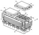
- FIG. 1is a top isometric view of an environmentally protected housing according to an embodiment of the present invention.
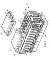
- FIG. 2is a top isometric view of a shell of the housing of FIG. 1 .
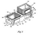
- FIG. 3is a bottom isometric view of the shell of FIG. 2 .
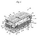
- FIG. 4is a exploded bottom isometric view of the housing of FIG. 1 .
- FIG. 5illustrates a portion of a heat sink of the housing of FIG. 1 according to another embodiment of the present invention.
- FIG. 6illustrates another heat sink of the housing of FIG. 1 according to another embodiment of the present invention.
- FIG. 7is an enlarged view of region 700 of FIG. 2 .
- Embodiments of the present inventionprovide a housing for circuit cards.
- the housingis interiorly lined with a thermally conductive liner that is integral with the housing.
- a protrusion of the linerextends through the housing and contacts the housing to form a pressure seal between the liner and the housing.
- a heat sinkis disposed on an exterior of the housing and is thermally coupled to the protrusion of the liner.
- a caseis disposed within the liner and is thermally coupled thereto. The case is adapted to receive a plurality of circuit cards so that the plurality of circuit cards is thermally coupled to the case. Therefore, the plurality of circuit cards is thermally coupled to the heat sink via the case and liner.
- the thermally conductive linerovercomes many of the sealing problems associated with heat sinks that extend through apertures within housings to thermally contact cases located within the housings for containing circuit cards.
- FIG. 1is a top isometric view of an environmentally protected housing 100 , such as an 819-type repeater housing, according to an embodiment of the present invention.
- Housing 100includes shell 102 that is selectively sealed against the weather and/or a pressure differential by a pair of first covers 104 and a second cover 106 located opposite first covers 104 .
- weatherincludes moisture, such as rain and/or humidity, salt fog, or the like.
- shell 102is divided into two compartments 108 . Each of compartments 108 receives a case 110 .
- Case 110includes a number of slots 112 adapted to respectively receive a number of circuit cards 114 , such as a repeater cards, line cards, or the like.
- FIGS. 2 and 3are respectively top and bottom isometric views of shell 102 .
- Shell 102has opposing end walls 116 having exterior surfaces 118 and opposing side walls 120 having exterior surfaces 122 .
- Liners 124are respectively disposed within and line compartments 108 , as shown in FIGS. 2 and 3 .
- liners 124are integral with shell 102 .
- shell 102is molded over liners 124 to form compartments 108 .
- liners 124are bonded to shell 102 .
- Liners 124are of a thermally conductive material, such as aluminum or the like.
- each of liners 124includes opposing side protrusions 126 and an end protrusion 128 .
- Side protrusions 126 of each of liners 124respectively extend through sidewalls 120 so that a surface 130 of each of side protrusions 126 is substantially flush with surface 122 of the respective sidewall 120 .
- the end protrusion 128 of each of liners 124extends through one of end walls 116 so that a surface 132 of end protrusion 128 is substantially flush with surface 118 of end wall 116 .
- a perimeter 190 of each of side protrusions 126 and the end protrusion 128 of each of liners 124as shown for one of side protrusions 126 in FIG.
- side protrusions 126 and end protrusion 128are integral with liner 124 .
- side protrusions 126 and end protrusion 128are attached to liner 124 by bolting, screwing, welding, brazing, or the like.
- Cases 110are respectively contained within liners 124 , as shown in FIG. 1 , and are respectively thermally coupled to liners 124 .
- case 110is thermally coupled to liner 124 by direct contact, e.g., achieved by fastening case 110 against liner 116 using cap screws, frictionally engaging case 110 and liner 124 , or the like.
- each of circuit cards 114is clamped within case 110 so that each of circuit cards 114 is thermally coupled to case 110 by direct contact, e.g., as described in U.S. patent application Ser. No. 09/919,006, entitled CLAMPING RECEPTACLE, filed on Jul. 31, 2001 and U.S. patent application Ser. No. 09/804,129, entitled MECHANICAL HOUSING, filed on Mar. 12, 2001, which applications are incorporated herein by reference.
- Each of compartments 108includes an aperture 140 , as shown in FIG. 2 , that is selectively sealed against the weather and/or a pressure differential by one of covers 104 .
- Shell 102has an aperture 142 , shown in FIG. 3 , opposite apertures 140 selectively sealed by cover 106 against the weather and/or a pressure differential.
- shell 102 , covers 104 , and cover 106are of glass-filled nylon or the like.
- Fasteners 144e.g., cap screws or the like, secure covers 104 to shell 102
- fasteners 146e.g., cap screws, bolts, or the like, secure cover 106 to shell 102 , as shown in FIG. 1 .
- FIG. 4is an exploded bottom isometric view of housing 100 .
- a side heat sink 148is attached to surface 130 of each of side protrusions 126 so as to make direct contact therewith. This thermally couples the side heat sink 148 with the respective one of liners 124 .
- An end heat sink 150is attached to surface 132 of each of end protrusions 128 . The end heat sink 150 makes direct contact with surface 132 , thus thermally coupling the end heat sink 150 to the respective liner 124 .
- side heat sinks 148 and end heat sinks 150respectively include fins 152 and 154 .
- Fasteners 156attach side heat sinks 148 and end heat sinks 150 respectively to surfaces 130 and 132 , as shown in FIG. 4 .
- side heat sinks 148 and end heat sinks 150are of a thermally conductive material, such as aluminum, copper, brass, or the like.
- Heatis conducted from each of circuit cards 114 to the respective cases 110 containing them via the direct contact between circuit cards 114 and the respective cases 110 .
- Heatis conducted from cases 110 to liners 124 via the direct contact between cases 110 and liners 124 .
- Heatis conducted from liners 126 through side protrusions 126 and end protrusions 128 respectively to side heat sinks 148 and end heat sinks 150 via direct contact between side protrusions 126 and side heat sinks 148 and direct between end protrusions 128 and end heat sinks 150 .
- Heatis transferred from side heat sinks 148 and end heat sinks 150 to an environment surrounding housing 100 .
- FIG. 4also shows a pair of backplanes 180 disposed within housing 100 .
- Circuit cards 114 of each of cases 110are respectively electrically connected to backplanes 180 .
- a single backplaneis used in place of the pair of backplanes 180 , as described in U.S. patent application Ser. No. 10/059,646, entitled BACKPLANE, filed on Jan. 29, 2002.
- FIG. 5illustrates side heat sink 148 according to another embodiment of the present invention.
- side heat sink 148includes a pad 502 secured to side heat sink 148 by fasteners, e.g., cap screws, welding, brazing, or the like.
- pad 502is integral with side heat sink 148 .
- a surface 505 of pad 502butts against surface 130 of one of side protrusions 126 to thermally couple side heat sink 148 to the respective one of liners 124 by direct contact.
- a groove 506is disposed in pad 502 around surface 505 for receiving a seal 508 that is compressed against surface 122 of sidewall 120 around side protrusion 126 to seal against a pressure differential and/or the weather.
- Through holes 510pass through side heat sink 148 .
- through holes 510respectively align with threaded blind holes 182 in surface 130 (shown in FIG. 4 ) of the respective side protrusion 126 .
- Fasteners 156pass through holes 510 and thread into threaded blind holes 182 to attach side heat sink to surface 130 .
- O-rings 512are received in recesses 514 , disposed in surface 505 around holes 510 . When surface 505 butts against surface 130 , O-rings 512 form a seal between the respective side protrusion 126 and side heat sink 148 that seals against a pressure differential and/or the weather.
- FIG. 6illustrates end heat sink 150 .
- end heat sink 150includes a pad 602 secured to end heat sink 150 by fasteners, e.g., cap screws, welding, brazing, or the like.
- pad 602is integral with end heat sink 150 .
- a surface 605 of pad 602butts against surface 132 of one of end protrusions 128 to thermally couple end heat sink 150 to the respective one of liners 124 by direct contact.
- a groove 606is disposed in pad 602 around surface 605 for receiving a seal 608 that is compressed against surface 118 of end wall 116 around end protrusion 128 to seal against a pressure differential and/or the weather.
- Through holes 610pass through end heat sink 150 .
- through holes 610respectively align with threaded blind holes 184 in surface 132 (shown in FIG. 4 ) of the respective end protrusion 128 .
- Fasteners 156pass through holes 610 and thread into threaded blind holes 184 to attach end heat sink to surface 132 .
- O-rings 612are received in recesses 614 , disposed in surface 605 around holes 610 . When surface 605 butts against surface 132 , O-rings 612 form a seal between the respective end protrusion 128 and end heat sink 150 that seals against a pressure differential and/or the weather.
- Molding shell 102 over liners 124forms the pressure seal between each of liners 124 and shell 102 at the perimeter 190 of each of side protrusions 126 and the end protrusion 128 .
- Thisovercomes many of the sealing problems associated with heat sinks that extend through apertures within housings to thermally contact cases located within the housings for containing circuit cards.
- the pressure seal between shell 102 and the respective liners 124seals shell 102 against a pressure differential of about 15 psi.
- FIG. 7is an enlarged cross-sectional view of region 700 of FIG. 2 illustrating perimeter 190 of one embodiment of a side protrusion 126 .
- perimeter 190includes rectangular slots 710 and semi-circular slots 720 .
- molten shell materialflows into slots 710 and 720 substantially filling them.
- ribs of shell materialextend into slots 710 and 720 of perimeter 190 to bond perimeter 190 to shell 102 . This forms the pressure seal between perimeter 190 and shell 102 .
- the pressure seal between perimeter 190 and shell 102also seals against the weather.
- the embodimentsprovide a housing for circuit cards.
- the housingis interiorly lined with a thermally conductive liner that is integral with the housing.
- a protrusion of the linerextends through the housing and contacts the housing to form a pressure seal between the liner and the housing.
- a heat sinkis disposed on an exterior of the housing and is thermally coupled to the protrusion of the liner.
- a caseis disposed within the liner and is thermally coupled thereto. The case is adapted to receive a plurality of circuit cards so that the plurality of circuit cards is thermally coupled to the case. Therefore, the plurality of circuit cards is thermally coupled to the heat sink via the case and liner.
- the thermally conductive linerovercomes many of the sealing problems associated with heat sinks that extend through apertures within housings to thermally contact cases located within the housings for containing circuit cards.
- housing 100is not limited to two compartments 108 .
- housing 100can have a single compartment 108 having a liner 124 , a case 110 , a cover 104 , and an opposing cover 106 .
- housing 100can have three or more compartments 108 each having a liner 124 and a case 110 , a cover 104 for covering each compartment, and a cover 106 . It is manifestly intended that this invention be limited only by the following claims and equivalents thereof.
Landscapes
- Engineering & Computer Science (AREA)
- Microelectronics & Electronic Packaging (AREA)
- Physics & Mathematics (AREA)
- Thermal Sciences (AREA)
- Casings For Electric Apparatus (AREA)
- Cooling Or The Like Of Electrical Apparatus (AREA)
Abstract
Description
Claims (31)
Priority Applications (2)
| Application Number | Priority Date | Filing Date | Title |
|---|---|---|---|
| US10/155,050US6862180B2 (en) | 2002-05-24 | 2002-05-24 | Housings for circuit cards |
| CA2429774ACA2429774C (en) | 2002-05-24 | 2003-05-23 | Housings for circuit cards |
Applications Claiming Priority (1)
| Application Number | Priority Date | Filing Date | Title |
|---|---|---|---|
| US10/155,050US6862180B2 (en) | 2002-05-24 | 2002-05-24 | Housings for circuit cards |
Publications (2)
| Publication Number | Publication Date |
|---|---|
| US20030218867A1 US20030218867A1 (en) | 2003-11-27 |
| US6862180B2true US6862180B2 (en) | 2005-03-01 |
Family
ID=29548991
Family Applications (1)
| Application Number | Title | Priority Date | Filing Date |
|---|---|---|---|
| US10/155,050Expired - LifetimeUS6862180B2 (en) | 2002-05-24 | 2002-05-24 | Housings for circuit cards |
Country Status (2)
| Country | Link |
|---|---|
| US (1) | US6862180B2 (en) |
| CA (1) | CA2429774C (en) |
Cited By (15)
| Publication number | Priority date | Publication date | Assignee | Title |
|---|---|---|---|---|
| US20060071068A1 (en)* | 2004-10-01 | 2006-04-06 | Toshiba Tec Kabushiki Kaisha | Merchandise sales data processing apparatus |
| US7372705B1 (en)* | 2006-02-01 | 2008-05-13 | Cisco Technology, Inc. | Portable data routing device and method of use |
| USD568841S1 (en) | 2006-12-21 | 2008-05-13 | Adc Telecommunications, Inc. | Enclosure for electronic components |
| US7385812B1 (en)* | 2006-02-03 | 2008-06-10 | Storage Technology Corporation | Method and apparatus for a thermally conductive packaging technique for cooling electronic systems |
| US7450382B1 (en) | 2007-05-15 | 2008-11-11 | Adc Telecommunications, Inc. | Apparatus for enclosing electronic components |
| US20080278915A1 (en)* | 2007-05-10 | 2008-11-13 | Adc Telecommunications, Inc. | Chassis mounted heat sink system |
| US20080291627A1 (en)* | 2007-05-23 | 2008-11-27 | Adc Telecommunications, Inc. | Apparatus for enclosing electronic components used in telecommunication systems |
| US20090231815A1 (en)* | 2008-03-12 | 2009-09-17 | Duk-Yong Kim | Enclosure device of wireless communication apparatus |
| US20100177478A1 (en)* | 2009-01-09 | 2010-07-15 | Lucius Chidi Akalanne | Cooling arrangement for an equipment assembly |
| US20100321898A1 (en)* | 2009-06-22 | 2010-12-23 | Innomedia Pte Ltd. | Electronic device with improved heat dissipation properties. |
| US20110317346A1 (en)* | 2010-06-28 | 2011-12-29 | Zte Corporation | Totally-enclosed integrative access system and power consumption reduction method thereof |
| US20120020017A1 (en)* | 2010-07-20 | 2012-01-26 | Kehret William E | Printed circuit board module enclosure and apparatus using same |
| US20120044635A1 (en)* | 2010-08-19 | 2012-02-23 | Apple Inc. | Internal frame optimized for stiffness and heat transfer |
| US20130050939A1 (en)* | 2011-08-28 | 2013-02-28 | Purewave Networks, Inc. | Methods and system for effectively removing heat from a wireless base station |
| USD835040S1 (en) | 2016-09-09 | 2018-12-04 | Corning Research & Development Corporation | 1×4 distribution point unit |
Families Citing this family (5)
| Publication number | Priority date | Publication date | Assignee | Title |
|---|---|---|---|---|
| DE10336610A1 (en)* | 2003-08-08 | 2005-03-10 | Siemens Ag | Housing for receiving printed circuit boards, the assembly of which forms at least parts of a communication system |
| DE102004013876A1 (en)* | 2004-03-20 | 2005-10-06 | Intergraph (Deutschland) Gmbh | Device for holding a storage medium |
| GB0721932D0 (en)* | 2007-11-08 | 2007-12-19 | Harp Visual Comm Ltd | Information display board |
| US7773378B2 (en)* | 2008-10-21 | 2010-08-10 | Moxa, Inc. | Heat-dissipating structure for expansion board architecture |
| US8913391B2 (en)* | 2012-01-30 | 2014-12-16 | Alcatel Lucent | Board-level heat transfer apparatus for communication platforms |
Citations (80)
| Publication number | Priority date | Publication date | Assignee | Title |
|---|---|---|---|---|
| US2737579A (en) | 1951-04-06 | 1956-03-06 | Acf Ind Inc | Amplifier assembly |
| US2796559A (en) | 1952-09-11 | 1957-06-18 | Bendix Aviat Corp | Electrical apparatus |
| US2833966A (en) | 1956-06-13 | 1958-05-06 | George N Goodier | Heat conducting tube mount |
| US2876277A (en) | 1954-12-29 | 1959-03-03 | Ibm | Electrical component mounting apparatus |
| US3087095A (en) | 1959-12-28 | 1963-04-23 | Bell Telephone Labor Inc | Cushion mounting for electrical apparatus |
| US3135321A (en) | 1960-03-07 | 1964-06-02 | Trane Co | Heat exchanger |
| US3366171A (en) | 1966-07-14 | 1968-01-30 | Bbc Brown Boveri & Cie | Heat sink for semi-conductor elements |
| US3467891A (en) | 1967-10-03 | 1969-09-16 | Gen Electric | Combination electrical,mechanical,and thermal connector assembly |
| US3487267A (en) | 1968-01-02 | 1969-12-30 | Jerrold Electronics Corp | Thermally conducting transistor support arms |
| US3697929A (en) | 1971-01-18 | 1972-10-10 | Bunker Ramo | Controlled insertion force receptacle for flat circuit bearing elements |
| US3767974A (en) | 1972-01-03 | 1973-10-23 | Cogar Corp | Insertion and extraction lever for printed circuit cards |
| US3809798A (en) | 1972-09-06 | 1974-05-07 | H Simon | Angle type feedthrough cable clamp |
| US3997819A (en) | 1974-09-09 | 1976-12-14 | Siemens Aktiengesellschaft | Housing for electrical communications and measuring devices |
| US4172212A (en) | 1978-07-24 | 1979-10-23 | International Telephone And Telegraph Corporation | Submarine housing for submarine cable system repeater components or the like |
| US4184539A (en) | 1978-07-10 | 1980-01-22 | The United States Of America As Represented By The Secretary Of The Navy | Electronic card mount and heat transfer assembly for underwater vehicles |
| US4259843A (en) | 1979-10-09 | 1981-04-07 | Cromemco Inc. | Isolation chamber for electronic devices |
| US4301494A (en) | 1979-09-28 | 1981-11-17 | Wescom, Inc. | Printed circuit board faceplate assembly |
| JPS58634A (en) | 1981-06-20 | 1983-01-05 | Yamaha Motor Co Ltd | Dry clutch |
| JPS58105187A (en) | 1981-12-17 | 1983-06-22 | 佐瀬 英三 | Flour mill model harnessing water wheel |
| US4449576A (en) | 1980-11-25 | 1984-05-22 | Kabel- Und Metallwerke | Heat-producing elements with heat pipes |
| JPS6026936A (en) | 1983-07-25 | 1985-02-09 | Olympus Optical Co Ltd | Control device for exposure |
| JPS6079834A (en) | 1983-10-07 | 1985-05-07 | Nec Corp | Structure of optical submarine repeater unit |
| US4528615A (en) | 1983-05-13 | 1985-07-09 | At&T Bell Laboratories | Repeater housing and circuit mounting structure |
| US4547833A (en) | 1983-12-23 | 1985-10-15 | Schlumberger Technology Corporation | High density electronics packaging system for hostile environment |
| US4559790A (en) | 1982-10-18 | 1985-12-24 | General Electric Company | Apparatus for maintaining electronic equipment and the like at low temperatures in hot ambient environments |
| US4564061A (en) | 1981-12-18 | 1986-01-14 | Ant Nachrichtentechnik Gmbh | Cooling system for communications devices with high power losses |
| JPS6267936A (en) | 1985-09-19 | 1987-03-27 | Fujitsu Ltd | wireless communication device |
| US4656559A (en) | 1984-05-10 | 1987-04-07 | Ultima Electronics Ltd. | Holder and heat sink for electronic components |
| JPS6279404A (en) | 1985-10-03 | 1987-04-11 | Nec Corp | Optical submarine repeater enclosure |
| US4662002A (en) | 1984-01-19 | 1987-04-28 | Standard Telephones And Cables Public Limited Company | Optical repeaters |
| US4679250A (en) | 1984-01-19 | 1987-07-07 | Standard Telephones And Cables Plc | Optical repeaters |
| GB2193552A (en) | 1986-08-08 | 1988-02-10 | Stc Plc | Repeater housing |
| US4777561A (en) | 1985-03-26 | 1988-10-11 | Hughes Aircraft Company | Electronic module with self-activated heat pipe |
| US4805482A (en) | 1987-08-24 | 1989-02-21 | Brunswick Corporation | Cam adjustment assembly |
| US4815913A (en) | 1987-03-20 | 1989-03-28 | Matsushita Electric Industrial Co., Ltd. | Electronic component mounting device |
| US4849858A (en) | 1986-10-20 | 1989-07-18 | Westinghouse Electric Corp. | Composite heat transfer means |
| US4858070A (en) | 1987-04-24 | 1989-08-15 | Racal Data Communications Inc. | Modular expandable housing arrangement for electronic apparatus |
| US4858068A (en) | 1986-03-21 | 1989-08-15 | Alcatel Cit | Electronic circuit housing |
| JPH024287A (en) | 1988-06-22 | 1990-01-09 | Olympus Optical Co Ltd | Display control system |
| JPH02166798A (en) | 1988-12-21 | 1990-06-27 | Nec Corp | Heat radiation structure for communication equipment case |
| US4953058A (en) | 1989-09-01 | 1990-08-28 | General Dynamics Corporation, Space Systems Div. | Modular segment adapted to provide a passively cooled housing for heat generating electronic modules |
| US4962445A (en) | 1988-04-21 | 1990-10-09 | Societe Anonyme Dite: Alcatel Cit | Housing for submersible equipment |
| US4962444A (en) | 1989-01-03 | 1990-10-09 | Sunstrand Corporation | Cold chassis for cooling electronic circuit components on an electronic board |
| US4987978A (en) | 1989-10-10 | 1991-01-29 | Jungersen Thoger G | Wheelchair safety brakes |
| US5019939A (en) | 1989-10-24 | 1991-05-28 | Ag Communication Systems Corp. | Thermal management plate |
| US5045971A (en) | 1989-04-18 | 1991-09-03 | Mitsubishi Denki Kabushiki Kaisha | Electronic device housing with temperature management functions |
| US5048793A (en) | 1990-06-14 | 1991-09-17 | Miller Pipeline Corporation | Pipe jack |
| US5089935A (en) | 1990-02-28 | 1992-02-18 | Mitsubishi Denki Kabushiki Kaisha | Control device case |
| US5105337A (en) | 1989-12-29 | 1992-04-14 | Alcatel Cit | Housing for underwater electronic circuits |
| US5267122A (en) | 1992-06-15 | 1993-11-30 | Alcatel Network Systems, Inc. | Optical network unit |
| US5309315A (en) | 1991-08-09 | 1994-05-03 | Pulse Embedded Computer Systems, Inc. | Severe environment enclosure with thermal heat sink and EMI protection |
| US5329425A (en) | 1991-02-25 | 1994-07-12 | Alcatel N.V. | Cooling system |
| US5424916A (en) | 1989-07-28 | 1995-06-13 | The Charles Stark Draper Laboratory, Inc. | Combination conductive and convective heatsink |
| US5432682A (en) | 1993-01-27 | 1995-07-11 | Raac Technologies, Inc. | AT computer card mounting bracket |
| JPH07177645A (en) | 1993-12-21 | 1995-07-14 | Nec Eng Ltd | Heat dissipating/shock absorbing structure for submarine repeater |
| JPH0865868A (en) | 1994-08-19 | 1996-03-08 | Nec Eng Ltd | Heat radiation/buffering structure of submarine repeater |
| US5519573A (en) | 1994-12-27 | 1996-05-21 | Intel Corporation | I/O riser card for motherboard in a personal computer/server |
| US5642264A (en) | 1991-04-01 | 1997-06-24 | E-Systems, Inc. | Apparatus for supporting circuit cards in slot locations |
| US5825621A (en)* | 1997-06-12 | 1998-10-20 | Harris Corporation | Closed loop cooling housing for printed circuit card-mounted, sealed heat exchanger |
| US5842514A (en) | 1997-03-05 | 1998-12-01 | Northern Telecom Limited | Electronic unit |
| US5896268A (en) | 1997-08-11 | 1999-04-20 | Abacon Telecommunications Corporation | Enclosure for high-density subscriber line modules |
| US5995378A (en) | 1997-12-31 | 1999-11-30 | Micron Technology, Inc. | Semiconductor device socket, assembly and methods |
| US6002588A (en) | 1997-12-04 | 1999-12-14 | Lockheed Martin Corporation | Thermally conductive vibration isolators |
| US6038129A (en) | 1998-04-28 | 2000-03-14 | Lucent Technologies Inc. | Cooling electronic apparatus |
| US6045140A (en) | 1997-07-11 | 2000-04-04 | Cummins Engine Company, Inc. | Retention gasket with cooperating cover |
| US6104611A (en) | 1995-10-05 | 2000-08-15 | Nortel Networks Corporation | Packaging system for thermally controlling the temperature of electronic equipment |
| US6118662A (en)* | 1999-11-05 | 2000-09-12 | Special Product Company | Enclosure for telecommunications equipment |
| EP1041002A2 (en) | 1999-04-01 | 2000-10-04 | Negesat Di Boer Fabrizio & C. SNC | Protective casing with cooling for equipment in air, space or land vehicles |
| US6209631B1 (en) | 1999-07-23 | 2001-04-03 | Esco Electronics Corporation | Thermal management apparatus for a sealed enclosure |
| US6292556B1 (en) | 1997-11-06 | 2001-09-18 | Anacapa Technology, Inc. | Local loop telecommunication repeater housings employing thermal collection, transfer and distribution via solid thermal conduction |
| US6289678B1 (en) | 1998-12-03 | 2001-09-18 | Phoenix Group, Inc. | Environmental system for rugged disk drive |
| US6295208B1 (en) | 1999-02-12 | 2001-09-25 | 3Com Corporation | Backplate for securing a circuit card to a computer chassis |
| US6310772B1 (en) | 1999-09-02 | 2001-10-30 | Special Product Company | Enclosure for telecommunications equipment |
| US6381146B1 (en) | 2000-09-28 | 2002-04-30 | Hewlett-Packard Company | Module removal system |
| US6396691B1 (en)* | 2000-04-17 | 2002-05-28 | Circa Telecom, Usa, Inc. | Thermal cover for T1/HDSL repeater case |
| US6404637B2 (en) | 2000-02-14 | 2002-06-11 | Special Product Company | Concentrical slot telecommunications equipment enclosure |
| US6406312B1 (en) | 2001-04-25 | 2002-06-18 | Juniper Networks, Inc. | Circuit card captivation and ejection mechanism including a lever to facilitate removal of the mechanism from a housing |
| US6430044B2 (en)* | 2000-02-10 | 2002-08-06 | Special Product Company | Telecommunications enclosure with individual, separated card holders |
| US6493236B1 (en) | 2001-05-29 | 2002-12-10 | Sony Computer Entertainment Inc. | Electronic equipment |
| US6587339B1 (en)* | 2002-03-29 | 2003-07-01 | Thornhurst Manufacturing, Inc. | Protective pot or container |
- 2002
- 2002-05-24USUS10/155,050patent/US6862180B2/ennot_activeExpired - Lifetime
- 2003
- 2003-05-23CACA2429774Apatent/CA2429774C/ennot_activeExpired - Fee Related
Patent Citations (83)
| Publication number | Priority date | Publication date | Assignee | Title |
|---|---|---|---|---|
| US2737579A (en) | 1951-04-06 | 1956-03-06 | Acf Ind Inc | Amplifier assembly |
| US2796559A (en) | 1952-09-11 | 1957-06-18 | Bendix Aviat Corp | Electrical apparatus |
| US2876277A (en) | 1954-12-29 | 1959-03-03 | Ibm | Electrical component mounting apparatus |
| US2833966A (en) | 1956-06-13 | 1958-05-06 | George N Goodier | Heat conducting tube mount |
| US3087095A (en) | 1959-12-28 | 1963-04-23 | Bell Telephone Labor Inc | Cushion mounting for electrical apparatus |
| US3135321A (en) | 1960-03-07 | 1964-06-02 | Trane Co | Heat exchanger |
| US3366171A (en) | 1966-07-14 | 1968-01-30 | Bbc Brown Boveri & Cie | Heat sink for semi-conductor elements |
| US3467891A (en) | 1967-10-03 | 1969-09-16 | Gen Electric | Combination electrical,mechanical,and thermal connector assembly |
| US3487267A (en) | 1968-01-02 | 1969-12-30 | Jerrold Electronics Corp | Thermally conducting transistor support arms |
| US3697929A (en) | 1971-01-18 | 1972-10-10 | Bunker Ramo | Controlled insertion force receptacle for flat circuit bearing elements |
| US3767974A (en) | 1972-01-03 | 1973-10-23 | Cogar Corp | Insertion and extraction lever for printed circuit cards |
| US3809798A (en) | 1972-09-06 | 1974-05-07 | H Simon | Angle type feedthrough cable clamp |
| US3997819A (en) | 1974-09-09 | 1976-12-14 | Siemens Aktiengesellschaft | Housing for electrical communications and measuring devices |
| US4184539A (en) | 1978-07-10 | 1980-01-22 | The United States Of America As Represented By The Secretary Of The Navy | Electronic card mount and heat transfer assembly for underwater vehicles |
| US4172212A (en) | 1978-07-24 | 1979-10-23 | International Telephone And Telegraph Corporation | Submarine housing for submarine cable system repeater components or the like |
| US4301494A (en) | 1979-09-28 | 1981-11-17 | Wescom, Inc. | Printed circuit board faceplate assembly |
| US4259843A (en) | 1979-10-09 | 1981-04-07 | Cromemco Inc. | Isolation chamber for electronic devices |
| US4449576A (en) | 1980-11-25 | 1984-05-22 | Kabel- Und Metallwerke | Heat-producing elements with heat pipes |
| JPS58634A (en) | 1981-06-20 | 1983-01-05 | Yamaha Motor Co Ltd | Dry clutch |
| JPS58105187A (en) | 1981-12-17 | 1983-06-22 | 佐瀬 英三 | Flour mill model harnessing water wheel |
| US4564061A (en) | 1981-12-18 | 1986-01-14 | Ant Nachrichtentechnik Gmbh | Cooling system for communications devices with high power losses |
| US4559790A (en) | 1982-10-18 | 1985-12-24 | General Electric Company | Apparatus for maintaining electronic equipment and the like at low temperatures in hot ambient environments |
| US4528615A (en) | 1983-05-13 | 1985-07-09 | At&T Bell Laboratories | Repeater housing and circuit mounting structure |
| JPS6026936A (en) | 1983-07-25 | 1985-02-09 | Olympus Optical Co Ltd | Control device for exposure |
| JPS6079834A (en) | 1983-10-07 | 1985-05-07 | Nec Corp | Structure of optical submarine repeater unit |
| US4547833A (en) | 1983-12-23 | 1985-10-15 | Schlumberger Technology Corporation | High density electronics packaging system for hostile environment |
| US4662002A (en) | 1984-01-19 | 1987-04-28 | Standard Telephones And Cables Public Limited Company | Optical repeaters |
| US4679250A (en) | 1984-01-19 | 1987-07-07 | Standard Telephones And Cables Plc | Optical repeaters |
| US4656559A (en) | 1984-05-10 | 1987-04-07 | Ultima Electronics Ltd. | Holder and heat sink for electronic components |
| US4777561A (en) | 1985-03-26 | 1988-10-11 | Hughes Aircraft Company | Electronic module with self-activated heat pipe |
| JPS6267936A (en) | 1985-09-19 | 1987-03-27 | Fujitsu Ltd | wireless communication device |
| JPS6279404A (en) | 1985-10-03 | 1987-04-11 | Nec Corp | Optical submarine repeater enclosure |
| US4858068A (en) | 1986-03-21 | 1989-08-15 | Alcatel Cit | Electronic circuit housing |
| GB2193552A (en) | 1986-08-08 | 1988-02-10 | Stc Plc | Repeater housing |
| US4849858A (en) | 1986-10-20 | 1989-07-18 | Westinghouse Electric Corp. | Composite heat transfer means |
| US4815913A (en) | 1987-03-20 | 1989-03-28 | Matsushita Electric Industrial Co., Ltd. | Electronic component mounting device |
| US4858070A (en) | 1987-04-24 | 1989-08-15 | Racal Data Communications Inc. | Modular expandable housing arrangement for electronic apparatus |
| US4805482A (en) | 1987-08-24 | 1989-02-21 | Brunswick Corporation | Cam adjustment assembly |
| US4962445A (en) | 1988-04-21 | 1990-10-09 | Societe Anonyme Dite: Alcatel Cit | Housing for submersible equipment |
| JPH024287A (en) | 1988-06-22 | 1990-01-09 | Olympus Optical Co Ltd | Display control system |
| JPH02166798A (en) | 1988-12-21 | 1990-06-27 | Nec Corp | Heat radiation structure for communication equipment case |
| US4962444A (en) | 1989-01-03 | 1990-10-09 | Sunstrand Corporation | Cold chassis for cooling electronic circuit components on an electronic board |
| US5045971A (en) | 1989-04-18 | 1991-09-03 | Mitsubishi Denki Kabushiki Kaisha | Electronic device housing with temperature management functions |
| US5424916A (en) | 1989-07-28 | 1995-06-13 | The Charles Stark Draper Laboratory, Inc. | Combination conductive and convective heatsink |
| US4953058A (en) | 1989-09-01 | 1990-08-28 | General Dynamics Corporation, Space Systems Div. | Modular segment adapted to provide a passively cooled housing for heat generating electronic modules |
| US4987978A (en) | 1989-10-10 | 1991-01-29 | Jungersen Thoger G | Wheelchair safety brakes |
| US5019939A (en) | 1989-10-24 | 1991-05-28 | Ag Communication Systems Corp. | Thermal management plate |
| US5105337A (en) | 1989-12-29 | 1992-04-14 | Alcatel Cit | Housing for underwater electronic circuits |
| US5089935A (en) | 1990-02-28 | 1992-02-18 | Mitsubishi Denki Kabushiki Kaisha | Control device case |
| US5048793A (en) | 1990-06-14 | 1991-09-17 | Miller Pipeline Corporation | Pipe jack |
| US5329425A (en) | 1991-02-25 | 1994-07-12 | Alcatel N.V. | Cooling system |
| US5642264A (en) | 1991-04-01 | 1997-06-24 | E-Systems, Inc. | Apparatus for supporting circuit cards in slot locations |
| US5309315A (en) | 1991-08-09 | 1994-05-03 | Pulse Embedded Computer Systems, Inc. | Severe environment enclosure with thermal heat sink and EMI protection |
| US5267122A (en) | 1992-06-15 | 1993-11-30 | Alcatel Network Systems, Inc. | Optical network unit |
| US5432682A (en) | 1993-01-27 | 1995-07-11 | Raac Technologies, Inc. | AT computer card mounting bracket |
| JPH07177645A (en) | 1993-12-21 | 1995-07-14 | Nec Eng Ltd | Heat dissipating/shock absorbing structure for submarine repeater |
| JPH0865868A (en) | 1994-08-19 | 1996-03-08 | Nec Eng Ltd | Heat radiation/buffering structure of submarine repeater |
| US5519573A (en) | 1994-12-27 | 1996-05-21 | Intel Corporation | I/O riser card for motherboard in a personal computer/server |
| US6104611A (en) | 1995-10-05 | 2000-08-15 | Nortel Networks Corporation | Packaging system for thermally controlling the temperature of electronic equipment |
| US5842514A (en) | 1997-03-05 | 1998-12-01 | Northern Telecom Limited | Electronic unit |
| US5825621A (en)* | 1997-06-12 | 1998-10-20 | Harris Corporation | Closed loop cooling housing for printed circuit card-mounted, sealed heat exchanger |
| US6045140A (en) | 1997-07-11 | 2000-04-04 | Cummins Engine Company, Inc. | Retention gasket with cooperating cover |
| US5896268A (en) | 1997-08-11 | 1999-04-20 | Abacon Telecommunications Corporation | Enclosure for high-density subscriber line modules |
| US6292556B1 (en) | 1997-11-06 | 2001-09-18 | Anacapa Technology, Inc. | Local loop telecommunication repeater housings employing thermal collection, transfer and distribution via solid thermal conduction |
| US6535603B2 (en) | 1997-11-06 | 2003-03-18 | Anacapa Technology, Inc. | Local loop telecommunication repeater housings employing thermal collection, transfer and distribution via solid thermal conduction |
| US6510223B2 (en) | 1997-11-06 | 2003-01-21 | Anacapa Technology, Inc. | Local loop telecommunication repeater housings employing thermal collection, transfer and distribution via solid thermal conduction |
| US6002588A (en) | 1997-12-04 | 1999-12-14 | Lockheed Martin Corporation | Thermally conductive vibration isolators |
| US5995378A (en) | 1997-12-31 | 1999-11-30 | Micron Technology, Inc. | Semiconductor device socket, assembly and methods |
| US6038129A (en) | 1998-04-28 | 2000-03-14 | Lucent Technologies Inc. | Cooling electronic apparatus |
| US6289678B1 (en) | 1998-12-03 | 2001-09-18 | Phoenix Group, Inc. | Environmental system for rugged disk drive |
| US6295208B1 (en) | 1999-02-12 | 2001-09-25 | 3Com Corporation | Backplate for securing a circuit card to a computer chassis |
| EP1041002A2 (en) | 1999-04-01 | 2000-10-04 | Negesat Di Boer Fabrizio & C. SNC | Protective casing with cooling for equipment in air, space or land vehicles |
| US6209631B1 (en) | 1999-07-23 | 2001-04-03 | Esco Electronics Corporation | Thermal management apparatus for a sealed enclosure |
| US6310772B1 (en) | 1999-09-02 | 2001-10-30 | Special Product Company | Enclosure for telecommunications equipment |
| US6118662A (en)* | 1999-11-05 | 2000-09-12 | Special Product Company | Enclosure for telecommunications equipment |
| US6430044B2 (en)* | 2000-02-10 | 2002-08-06 | Special Product Company | Telecommunications enclosure with individual, separated card holders |
| US6611426B2 (en)* | 2000-02-10 | 2003-08-26 | Special Products Company | Telecommunications enclosure with individual, separated card holders |
| US6404637B2 (en) | 2000-02-14 | 2002-06-11 | Special Product Company | Concentrical slot telecommunications equipment enclosure |
| US6396691B1 (en)* | 2000-04-17 | 2002-05-28 | Circa Telecom, Usa, Inc. | Thermal cover for T1/HDSL repeater case |
| US6381146B1 (en) | 2000-09-28 | 2002-04-30 | Hewlett-Packard Company | Module removal system |
| US6406312B1 (en) | 2001-04-25 | 2002-06-18 | Juniper Networks, Inc. | Circuit card captivation and ejection mechanism including a lever to facilitate removal of the mechanism from a housing |
| US6493236B1 (en) | 2001-05-29 | 2002-12-10 | Sony Computer Entertainment Inc. | Electronic equipment |
| US6587339B1 (en)* | 2002-03-29 | 2003-07-01 | Thornhurst Manufacturing, Inc. | Protective pot or container |
Non-Patent Citations (11)
| Title |
|---|
| "Hardened Telecom Enclosures for Optimal Thermal Management of Electronics", SPC TelEquip, pp. 1-20, date unknown. |
| Abacon Telecommunications, HDSL High Capacity Repeater Case, 2 pgs., date unknown. |
| Abacon Telecommunications, HDSL Low Capacity Repeater Case, 1 pg., date unknown. |
| Circa Enterprises, Inc. "Digital Repeater Housings-HDSL Repeater", 2 pgs., 2000. |
| Circa Enterprises, Inc. "Digital Repeater Housings-T1 Repeater", 2 pgs., 2000. |
| Gary Gustine et al., U.S. patent application No. 09/804,129, "Mechanical Housing", filed Mar. 12, 2001. |
| Gary Gustine et al., U.S. patent application No. 09/918,989, "Clamping Case", filed Jul. 31, 2001. |
| Gary Gustine et al., U.S. patent application No. 09/919,006, "Clamping Receptacle", filed Jul. 31, 2001. |
| Joe Ricke Sr., "Managing Heat in Electronic Enclosures," Electronic Packaging & Production, pp. 87-88, 90, 92, vol. 36, No. 2, Feb. 1996. |
| Seri Lee, "How to Select a Heat Sink," Electronics Cooling, 9 pgs., Oct. 6, 2000. |
| Su, "Case for Mounting Slidably a Data Storage Medium in a Computer Housing" Patent Publication No. US 2002/0141153 A1, Filed Jul. 9, 2001, Published Oct. 3, 2002. (9 pgs.). |
Cited By (23)
| Publication number | Priority date | Publication date | Assignee | Title |
|---|---|---|---|---|
| US20060071068A1 (en)* | 2004-10-01 | 2006-04-06 | Toshiba Tec Kabushiki Kaisha | Merchandise sales data processing apparatus |
| US7372705B1 (en)* | 2006-02-01 | 2008-05-13 | Cisco Technology, Inc. | Portable data routing device and method of use |
| US7385812B1 (en)* | 2006-02-03 | 2008-06-10 | Storage Technology Corporation | Method and apparatus for a thermally conductive packaging technique for cooling electronic systems |
| USD568841S1 (en) | 2006-12-21 | 2008-05-13 | Adc Telecommunications, Inc. | Enclosure for electronic components |
| US20080278915A1 (en)* | 2007-05-10 | 2008-11-13 | Adc Telecommunications, Inc. | Chassis mounted heat sink system |
| US7457123B1 (en) | 2007-05-10 | 2008-11-25 | Adc Telecommunications, Inc. | Chassis mounted heat sink system |
| US7450382B1 (en) | 2007-05-15 | 2008-11-11 | Adc Telecommunications, Inc. | Apparatus for enclosing electronic components |
| US20080285231A1 (en)* | 2007-05-15 | 2008-11-20 | Adc Telecommunications, Inc. | Apparatus for enclosing electronic components |
| US20080291627A1 (en)* | 2007-05-23 | 2008-11-27 | Adc Telecommunications, Inc. | Apparatus for enclosing electronic components used in telecommunication systems |
| US7535716B2 (en) | 2007-05-23 | 2009-05-19 | Adc Telecommunications, Inc. | Apparatus for enclosing electronic components used in telecommunication systems |
| US20090231815A1 (en)* | 2008-03-12 | 2009-09-17 | Duk-Yong Kim | Enclosure device of wireless communication apparatus |
| US8004844B2 (en)* | 2008-03-12 | 2011-08-23 | Kmw, Inc. | Enclosure device of wireless communication apparatus |
| US20100177478A1 (en)* | 2009-01-09 | 2010-07-15 | Lucius Chidi Akalanne | Cooling arrangement for an equipment assembly |
| US20100321898A1 (en)* | 2009-06-22 | 2010-12-23 | Innomedia Pte Ltd. | Electronic device with improved heat dissipation properties. |
| US7907412B2 (en)* | 2009-06-22 | 2011-03-15 | Innomedia Pte Ltd | Electronic device with improved heat dissipation properties |
| US20110317346A1 (en)* | 2010-06-28 | 2011-12-29 | Zte Corporation | Totally-enclosed integrative access system and power consumption reduction method thereof |
| US20120020017A1 (en)* | 2010-07-20 | 2012-01-26 | Kehret William E | Printed circuit board module enclosure and apparatus using same |
| US8427828B2 (en)* | 2010-07-20 | 2013-04-23 | Themis Computer | Printed circuit board module enclosure and apparatus using same |
| US20120044635A1 (en)* | 2010-08-19 | 2012-02-23 | Apple Inc. | Internal frame optimized for stiffness and heat transfer |
| US8391010B2 (en)* | 2010-08-19 | 2013-03-05 | Apple Inc. | Internal frame optimized for stiffness and heat transfer |
| US9049801B2 (en) | 2010-08-19 | 2015-06-02 | Apple Inc. | Internal frame optimized for stiffness and heat transfer |
| US20130050939A1 (en)* | 2011-08-28 | 2013-02-28 | Purewave Networks, Inc. | Methods and system for effectively removing heat from a wireless base station |
| USD835040S1 (en) | 2016-09-09 | 2018-12-04 | Corning Research & Development Corporation | 1×4 distribution point unit |
Also Published As
| Publication number | Publication date |
|---|---|
| CA2429774A1 (en) | 2003-11-24 |
| US20030218867A1 (en) | 2003-11-27 |
| CA2429774C (en) | 2010-10-19 |
Similar Documents
| Publication | Publication Date | Title |
|---|---|---|
| US6862180B2 (en) | Housings for circuit cards | |
| US7633757B2 (en) | Mechanical housing | |
| US6702593B2 (en) | Connector apparatus for hardware | |
| US7719833B2 (en) | Electronic control device | |
| US6778388B1 (en) | Water-resistant electronic enclosure having a heat sink | |
| US5777850A (en) | Built-in control device for actuating loads with conductor foil-covered printed circuit board | |
| EP1198978B1 (en) | Utilizing a convection cooled electronic circuit card for producing a conduction cooled electronic card module | |
| US6587339B1 (en) | Protective pot or container | |
| CA2120468A1 (en) | Electronic module containing an internally ribbed, integral heat sink and bonded, flexible printed wiring board with two-sided component population | |
| US20220349220A1 (en) | Vehicle outside door handle with radar module and thermal management | |
| US6273181B1 (en) | Cooling device for electronic parts of vehicle | |
| US7473845B2 (en) | Structural unit and method for the production of a structural unit | |
| US20070180680A1 (en) | Enhanced heat transfer for housings | |
| US20240098925A1 (en) | Housing unit for an electronic component of an electrical refrigerant compressor | |
| US7773379B2 (en) | Module assembly having heat transfer plate | |
| US7209360B1 (en) | Leak-tight system for boxes containing electrical and electronic components | |
| US5187642A (en) | Lightweight sealed circuit board assembly | |
| US5422790A (en) | Computer chip mounting hardware for heat dissipation | |
| US5880933A (en) | Heat sinking module cover | |
| US20040095829A1 (en) | Ruggedised solid-state storage device | |
| CN219643782U (en) | Frequency converter structure meeting protection of UL-Type shell | |
| US20220217854A1 (en) | Sealed and unsealed electronic assemblies using common design | |
| US20030184981A1 (en) | Protective pot or container | |
| US10986723B2 (en) | Heat sink tray for printed circuit boards | |
| JP2007300198A (en) | Sealing structure of electric equipment |
Legal Events
| Date | Code | Title | Description |
|---|---|---|---|
| AS | Assignment | Owner name:ADC DSL SYSTEMS, INC., MINNESOTA Free format text:ASSIGNMENT OF ASSIGNORS INTEREST;ASSIGNORS:SAWYER, MICHAEL;KUSZ, MATTHEW J.;GUSTINE, GARY;AND OTHERS;REEL/FRAME:012941/0053;SIGNING DATES FROM 20020516 TO 20020524 | |
| AS | Assignment | Owner name:ADC DSL SYSTEMS, INC., MINNESOTA Free format text:ASSIGNMENT OF ASSIGNORS INTEREST;ASSIGNOR:DANIELS, FREDRICK A.;REEL/FRAME:014431/0578 Effective date:20040211 | |
| STCF | Information on status: patent grant | Free format text:PATENTED CASE | |
| FPAY | Fee payment | Year of fee payment:4 | |
| FPAY | Fee payment | Year of fee payment:8 | |
| AS | Assignment | Owner name:WILMINGTON TRUST, NATIONAL ASSOCIATION, AS THE COL Free format text:PATENT SECURITY AGREEMENT;ASSIGNOR:ADC DSL SYSTEMS, INC.;REEL/FRAME:036718/0042 Effective date:20150928 Owner name:JPMORGAN CHASE BANK, N.A., AS COLLATERAL AGENT, IL Free format text:PATENT SECURITY AGREEMENT - TERM LOAN;ASSIGNOR:ADC DSL SYSTEMS, INC.;REEL/FRAME:036714/0808 Effective date:20150928 Owner name:JPMORGAN CHASE BANK, N.A., AS COLLATERAL AGENT, IL Free format text:PATENT SECURITY AGREEMENT - ABL;ASSIGNOR:ADC DSL SYSTEMS, INC.;REEL/FRAME:036715/0164 Effective date:20150928 | |
| FPAY | Fee payment | Year of fee payment:12 | |
| AS | Assignment | Owner name:COMMSCOPE DSL SYSTEMS LLC (FORMERLY KNOWN AS ADC D Free format text:RELEASE OF SECURITY INTEREST IN PATENTS (RELEASES RF 036718/0042);ASSIGNOR:WILMINGTON TRUST, NATIONAL ASSOCIATION;REEL/FRAME:042126/0050 Effective date:20170317 | |
| AS | Assignment | Owner name:COMMSCOPE DSL SYSTEMS LLC, NORTH CAROLINA Free format text:CHANGE OF NAME;ASSIGNOR:ADC DSL SYSTEMS, INC.;REEL/FRAME:059644/0074 Effective date:20160101 |