US6861984B2 - Position location using broadcast digital television signals - Google Patents
Position location using broadcast digital television signalsDownload PDFInfo
- Publication number
- US6861984B2 US6861984B2US10/210,847US21084702AUS6861984B2US 6861984 B2US6861984 B2US 6861984B2US 21084702 AUS21084702 AUS 21084702AUS 6861984 B2US6861984 B2US 6861984B2
- Authority
- US
- United States
- Prior art keywords
- user terminal
- dtv
- pseudo
- determining
- ranges
- Prior art date
- Legal status (The legal status is an assumption and is not a legal conclusion. Google has not performed a legal analysis and makes no representation as to the accuracy of the status listed.)
- Expired - Lifetime
Links
- 238000000034methodMethods0.000claimsabstractdescription80
- 238000004590computer programMethods0.000claimsabstractdescription44
- 230000005540biological transmissionEffects0.000claimsdescription10
- 238000012544monitoring processMethods0.000claimsdescription5
- 230000000694effectsEffects0.000description13
- 230000001427coherent effectEffects0.000description11
- 230000008569processEffects0.000description10
- 230000001413cellular effectEffects0.000description8
- 238000012545processingMethods0.000description7
- 238000004891communicationMethods0.000description6
- 239000000203mixtureSubstances0.000description6
- 238000004088simulationMethods0.000description6
- 230000000875corresponding effectEffects0.000description5
- 238000005259measurementMethods0.000description5
- 238000005070samplingMethods0.000description5
- 238000001228spectrumMethods0.000description5
- 239000004165Methyl ester of fatty acidsSubstances0.000description4
- 238000005311autocorrelation functionMethods0.000description4
- 230000008901benefitEffects0.000description4
- 238000004364calculation methodMethods0.000description4
- 238000007796conventional methodMethods0.000description4
- 230000006870functionEffects0.000description4
- 230000010354integrationEffects0.000description4
- 238000013459approachMethods0.000description3
- 238000001514detection methodMethods0.000description3
- 238000001914filtrationMethods0.000description3
- 230000001360synchronised effectEffects0.000description3
- 238000012937correctionMethods0.000description2
- 229920001690polydopaminePolymers0.000description2
- 239000004065semiconductorSubstances0.000description2
- 238000012546transferMethods0.000description2
- 238000010521absorption reactionMethods0.000description1
- 230000015556catabolic processEffects0.000description1
- 230000008859changeEffects0.000description1
- 238000010276constructionMethods0.000description1
- 230000002596correlated effectEffects0.000description1
- 238000005314correlation functionMethods0.000description1
- 238000013500data storageMethods0.000description1
- 238000006731degradation reactionMethods0.000description1
- 238000010586diagramMethods0.000description1
- 238000004870electrical engineeringMethods0.000description1
- 238000005516engineering processMethods0.000description1
- 239000000284extractSubstances0.000description1
- 230000000116mitigating effectEffects0.000description1
- 238000012986modificationMethods0.000description1
- 230000004048modificationEffects0.000description1
- 230000003287optical effectEffects0.000description1
- 230000003134recirculating effectEffects0.000description1
- 238000011160researchMethods0.000description1
- 230000004044responseEffects0.000description1
- WFKWXMTUELFFGS-UHFFFAOYSA-NtungstenChemical compound[W]WFKWXMTUELFFGS-UHFFFAOYSA-N0.000description1
Images


Classifications
- G—PHYSICS
- G01—MEASURING; TESTING
- G01C—MEASURING DISTANCES, LEVELS OR BEARINGS; SURVEYING; NAVIGATION; GYROSCOPIC INSTRUMENTS; PHOTOGRAMMETRY OR VIDEOGRAMMETRY
- G01C21/00—Navigation; Navigational instruments not provided for in groups G01C1/00 - G01C19/00
- G01C21/20—Instruments for performing navigational calculations
- G01C21/206—Instruments for performing navigational calculations specially adapted for indoor navigation
- G—PHYSICS
- G01—MEASURING; TESTING
- G01S—RADIO DIRECTION-FINDING; RADIO NAVIGATION; DETERMINING DISTANCE OR VELOCITY BY USE OF RADIO WAVES; LOCATING OR PRESENCE-DETECTING BY USE OF THE REFLECTION OR RERADIATION OF RADIO WAVES; ANALOGOUS ARRANGEMENTS USING OTHER WAVES
- G01S19/00—Satellite radio beacon positioning systems; Determining position, velocity or attitude using signals transmitted by such systems
- G01S19/38—Determining a navigation solution using signals transmitted by a satellite radio beacon positioning system
- G01S19/39—Determining a navigation solution using signals transmitted by a satellite radio beacon positioning system the satellite radio beacon positioning system transmitting time-stamped messages, e.g. GPS [Global Positioning System], GLONASS [Global Orbiting Navigation Satellite System] or GALILEO
- G01S19/42—Determining position
- G01S19/45—Determining position by combining measurements of signals from the satellite radio beacon positioning system with a supplementary measurement
- G01S19/46—Determining position by combining measurements of signals from the satellite radio beacon positioning system with a supplementary measurement the supplementary measurement being of a radio-wave signal type
- G—PHYSICS
- G01—MEASURING; TESTING
- G01S—RADIO DIRECTION-FINDING; RADIO NAVIGATION; DETERMINING DISTANCE OR VELOCITY BY USE OF RADIO WAVES; LOCATING OR PRESENCE-DETECTING BY USE OF THE REFLECTION OR RERADIATION OF RADIO WAVES; ANALOGOUS ARRANGEMENTS USING OTHER WAVES
- G01S5/00—Position-fixing by co-ordinating two or more direction or position line determinations; Position-fixing by co-ordinating two or more distance determinations
- G01S5/0009—Transmission of position information to remote stations
- G01S5/0018—Transmission from mobile station to base station
- G01S5/0036—Transmission from mobile station to base station of measured values, i.e. measurement on mobile and position calculation on base station
- G—PHYSICS
- G01—MEASURING; TESTING
- G01S—RADIO DIRECTION-FINDING; RADIO NAVIGATION; DETERMINING DISTANCE OR VELOCITY BY USE OF RADIO WAVES; LOCATING OR PRESENCE-DETECTING BY USE OF THE REFLECTION OR RERADIATION OF RADIO WAVES; ANALOGOUS ARRANGEMENTS USING OTHER WAVES
- G01S5/00—Position-fixing by co-ordinating two or more direction or position line determinations; Position-fixing by co-ordinating two or more distance determinations
- G01S5/0009—Transmission of position information to remote stations
- G01S5/0045—Transmission from base station to mobile station
- G01S5/0054—Transmission from base station to mobile station of actual mobile position, i.e. position calculation on base station
- G—PHYSICS
- G01—MEASURING; TESTING
- G01S—RADIO DIRECTION-FINDING; RADIO NAVIGATION; DETERMINING DISTANCE OR VELOCITY BY USE OF RADIO WAVES; LOCATING OR PRESENCE-DETECTING BY USE OF THE REFLECTION OR RERADIATION OF RADIO WAVES; ANALOGOUS ARRANGEMENTS USING OTHER WAVES
- G01S5/00—Position-fixing by co-ordinating two or more direction or position line determinations; Position-fixing by co-ordinating two or more distance determinations
- G01S5/0009—Transmission of position information to remote stations
- G01S5/0081—Transmission between base stations
- G—PHYSICS
- G01—MEASURING; TESTING
- G01S—RADIO DIRECTION-FINDING; RADIO NAVIGATION; DETERMINING DISTANCE OR VELOCITY BY USE OF RADIO WAVES; LOCATING OR PRESENCE-DETECTING BY USE OF THE REFLECTION OR RERADIATION OF RADIO WAVES; ANALOGOUS ARRANGEMENTS USING OTHER WAVES
- G01S5/00—Position-fixing by co-ordinating two or more direction or position line determinations; Position-fixing by co-ordinating two or more distance determinations
- G01S5/02—Position-fixing by co-ordinating two or more direction or position line determinations; Position-fixing by co-ordinating two or more distance determinations using radio waves
- G01S5/0205—Details
- G01S5/021—Calibration, monitoring or correction
- G—PHYSICS
- G01—MEASURING; TESTING
- G01S—RADIO DIRECTION-FINDING; RADIO NAVIGATION; DETERMINING DISTANCE OR VELOCITY BY USE OF RADIO WAVES; LOCATING OR PRESENCE-DETECTING BY USE OF THE REFLECTION OR RERADIATION OF RADIO WAVES; ANALOGOUS ARRANGEMENTS USING OTHER WAVES
- G01S5/00—Position-fixing by co-ordinating two or more direction or position line determinations; Position-fixing by co-ordinating two or more distance determinations
- G01S5/02—Position-fixing by co-ordinating two or more direction or position line determinations; Position-fixing by co-ordinating two or more distance determinations using radio waves
- G01S5/0205—Details
- G01S5/0218—Multipath in signal reception
- G—PHYSICS
- G01—MEASURING; TESTING
- G01S—RADIO DIRECTION-FINDING; RADIO NAVIGATION; DETERMINING DISTANCE OR VELOCITY BY USE OF RADIO WAVES; LOCATING OR PRESENCE-DETECTING BY USE OF THE REFLECTION OR RERADIATION OF RADIO WAVES; ANALOGOUS ARRANGEMENTS USING OTHER WAVES
- G01S5/00—Position-fixing by co-ordinating two or more direction or position line determinations; Position-fixing by co-ordinating two or more distance determinations
- G01S5/02—Position-fixing by co-ordinating two or more direction or position line determinations; Position-fixing by co-ordinating two or more distance determinations using radio waves
- G01S5/0205—Details
- G01S5/0221—Receivers
- G01S5/02213—Receivers arranged in a network for determining the position of a transmitter
- G—PHYSICS
- G01—MEASURING; TESTING
- G01S—RADIO DIRECTION-FINDING; RADIO NAVIGATION; DETERMINING DISTANCE OR VELOCITY BY USE OF RADIO WAVES; LOCATING OR PRESENCE-DETECTING BY USE OF THE REFLECTION OR RERADIATION OF RADIO WAVES; ANALOGOUS ARRANGEMENTS USING OTHER WAVES
- G01S5/00—Position-fixing by co-ordinating two or more direction or position line determinations; Position-fixing by co-ordinating two or more distance determinations
- G01S5/02—Position-fixing by co-ordinating two or more direction or position line determinations; Position-fixing by co-ordinating two or more distance determinations using radio waves
- G01S5/14—Determining absolute distances from a plurality of spaced points of known location
- G01S5/145—Using a supplementary range measurement, e.g. based on pseudo-range measurements
- H—ELECTRICITY
- H04—ELECTRIC COMMUNICATION TECHNIQUE
- H04N—PICTORIAL COMMUNICATION, e.g. TELEVISION
- H04N21/00—Selective content distribution, e.g. interactive television or video on demand [VOD]
- H04N21/20—Servers specifically adapted for the distribution of content, e.g. VOD servers; Operations thereof
- H04N21/25—Management operations performed by the server for facilitating the content distribution or administrating data related to end-users or client devices, e.g. end-user or client device authentication, learning user preferences for recommending movies
- H04N21/258—Client or end-user data management, e.g. managing client capabilities, user preferences or demographics, processing of multiple end-users preferences to derive collaborative data
- H04N21/25808—Management of client data
- H04N21/25841—Management of client data involving the geographical location of the client
- H—ELECTRICITY
- H04—ELECTRIC COMMUNICATION TECHNIQUE
- H04N—PICTORIAL COMMUNICATION, e.g. TELEVISION
- H04N21/00—Selective content distribution, e.g. interactive television or video on demand [VOD]
- H04N21/20—Servers specifically adapted for the distribution of content, e.g. VOD servers; Operations thereof
- H04N21/25—Management operations performed by the server for facilitating the content distribution or administrating data related to end-users or client devices, e.g. end-user or client device authentication, learning user preferences for recommending movies
- H04N21/266—Channel or content management, e.g. generation and management of keys and entitlement messages in a conditional access system, merging a VOD unicast channel into a multicast channel
- H04N21/2662—Controlling the complexity of the video stream, e.g. by scaling the resolution or bitrate of the video stream based on the client capabilities
- H—ELECTRICITY
- H04—ELECTRIC COMMUNICATION TECHNIQUE
- H04N—PICTORIAL COMMUNICATION, e.g. TELEVISION
- H04N21/00—Selective content distribution, e.g. interactive television or video on demand [VOD]
- H04N21/20—Servers specifically adapted for the distribution of content, e.g. VOD servers; Operations thereof
- H04N21/25—Management operations performed by the server for facilitating the content distribution or administrating data related to end-users or client devices, e.g. end-user or client device authentication, learning user preferences for recommending movies
- H04N21/266—Channel or content management, e.g. generation and management of keys and entitlement messages in a conditional access system, merging a VOD unicast channel into a multicast channel
- H04N21/2668—Creating a channel for a dedicated end-user group, e.g. insertion of targeted commercials based on end-user profiles
- H—ELECTRICITY
- H04—ELECTRIC COMMUNICATION TECHNIQUE
- H04N—PICTORIAL COMMUNICATION, e.g. TELEVISION
- H04N21/00—Selective content distribution, e.g. interactive television or video on demand [VOD]
- H04N21/40—Client devices specifically adapted for the reception of or interaction with content, e.g. set-top-box [STB]; Operations thereof
- H04N21/41—Structure of client; Structure of client peripherals
- H04N21/414—Specialised client platforms, e.g. receiver in car or embedded in a mobile appliance
- H04N21/41422—Specialised client platforms, e.g. receiver in car or embedded in a mobile appliance located in transportation means, e.g. personal vehicle
- H—ELECTRICITY
- H04—ELECTRIC COMMUNICATION TECHNIQUE
- H04N—PICTORIAL COMMUNICATION, e.g. TELEVISION
- H04N21/00—Selective content distribution, e.g. interactive television or video on demand [VOD]
- H04N21/60—Network structure or processes for video distribution between server and client or between remote clients; Control signalling between clients, server and network components; Transmission of management data between server and client, e.g. sending from server to client commands for recording incoming content stream; Communication details between server and client
- H04N21/61—Network physical structure; Signal processing
- H04N21/615—Signal processing at physical level
- H—ELECTRICITY
- H04—ELECTRIC COMMUNICATION TECHNIQUE
- H04N—PICTORIAL COMMUNICATION, e.g. TELEVISION
- H04N21/00—Selective content distribution, e.g. interactive television or video on demand [VOD]
- H04N21/80—Generation or processing of content or additional data by content creator independently of the distribution process; Content per se
- H04N21/81—Monomedia components thereof
- H04N21/8126—Monomedia components thereof involving additional data, e.g. news, sports, stocks, weather forecasts
- A—HUMAN NECESSITIES
- A63—SPORTS; GAMES; AMUSEMENTS
- A63F—CARD, BOARD, OR ROULETTE GAMES; INDOOR GAMES USING SMALL MOVING PLAYING BODIES; VIDEO GAMES; GAMES NOT OTHERWISE PROVIDED FOR
- A63F2300/00—Features of games using an electronically generated display having two or more dimensions, e.g. on a television screen, showing representations related to the game
- A63F2300/20—Features of games using an electronically generated display having two or more dimensions, e.g. on a television screen, showing representations related to the game characterised by details of the game platform
- A63F2300/205—Features of games using an electronically generated display having two or more dimensions, e.g. on a television screen, showing representations related to the game characterised by details of the game platform for detecting the geographical location of the game platform
Definitions
- the present inventionrelates generally to position determination, and particularly to position determination using DTV signals.
- GPSGlobal Positioning System
- GPSGlobal Positioning System-Theory and Applications, Volumes I and II, AIAA, Washington, D.C. 1996.
- GPShas revolutionized the technology of navigation and position location. However in some situations, GPS is less effective. Because the GPS signals are transmitted at relatively low power levels (less than 100 watts) and over great distances, the received signal strength is relatively weak (on the order of ⁇ 160 dBw as received by an omni-directional antenna). Thus the signal is marginally useful or not useful at all in the presence of blockage or inside a building.
- the inventionfeatures a computer program product, apparatus, and method for determining the position of a user terminal. It includes receiving at the user terminal a plurality of digital television (DTV) broadcast signals from a plurality of DTV transmitters, determining a pseudo-range between the user terminal and each DTV transmitter based on the DTV broadcast signals, and determining a position of the user terminal based on the pseudo-ranges and a location of each of the DTV transmitters.
- DTVdigital television
- Determining a position of the user terminalincludes adjusting the pseudo-ranges based on a difference between a transmitter clock at one of the DTV transmitters and a known time reference.
- the DTV broadcast signalis an American Television Standards Committee (ATSC) DTV signal, and the pseudo-ranges are determined based on a known digital sequence in the ATSC frame.
- the known digital sequenceis a synchronization code.
- the synchronization codeis a Field Synchronization Segment within an ATSC data frame.
- the synchronization codeis a Synchronization Segment within a Data Segment within an ATSC data frame.
- Determining a position of the user terminalincludes determining an offset between a local time reference in the user terminal and a master time reference.
- Implementationsinclude determining a subsequent position of the user terminal using the offset. Determining a pseudo-range includes storing a portion of each of the DTV signals; and subsequently correlating each of the stored portions and a signal generated by the user terminal to produce the pseudo-ranges. Determining a pseudo-range includes correlating each of the DTV signals with a signal generated by the user terminal as the DTV signals are received to produce the pseudo-ranges. Determining a position of the user terminal includes determining a general geographic area within which the user terminal is located; and determining the position of the user terminal based on the pseudo-ranges and the geographic area. The geographic area is a footprint of an additional transmitter communicably linked to the user terminal.
- Implementationsinclude scanning available DTV signals to assemble a fingerprint of the location; and selecting the DTV broadcast signals used to determine the pseudo-ranges based on the fingerprint and a stored table that matches known fingerprints with known locations. Implementations include using receiver autonomous integrity monitoring (RAIM) to check the integrity of each pseudo-range based on redundant pseudo-ranges from the DTV transmitters
- RAIMreceiver autonomous integrity monitoring
- Implementations of the inventionmay be used to position cellular telephones, wireless PDA's (personal digital assistant), pagers, cars, OCDMA (orthogonal code-division multiple access) transmitters and a host of other devices.
- Implementations of the inventionsmake use of a DTV signal which has excellent coverage over the United States, and the existence of which is mandated by the Federal Communication Commission. Implementations of the present invention require no changes to the Digital Broadcast Stations.
- the DTV signalhas a power advantage over GPS of more than 40 dB, and substantially superior geometry to that which a satellite system could provide, thereby permitting position location even in the presence of blockage and indoors.
- the DTV signalhas roughly six times the bandwidth of GPS, thereby minimizing the effects of multipath. Due to the high power and low duty factor of the DTV signal used for ranging, the processing requirements are minimal. Implementations of the present invention accommodate far cheaper, lower-speed, and lower-power devices than a GPS technique would require.
- the DTV signalIn contrast to satellite systems such as GPS, the range between the DTV transmitters and the user terminals changes very slowly. Therefore the DTV signal is not significantly affected by Doppler effects. This permits the signal to be integrated for a long period of time, resulting in very efficient signal acquisition.
- the frequency of the DTV signalis substantially lower that that of conventional cellular telephone systems, and so has better propagation characteristics.
- the DTV signalexperiences greater diffraction than cellular signals, and so is less affected by hills and has a larger horizon.
- the signalhas better propagations characteristics through buildings and automobiles.
- implementations of the present inventionrequire no change to the hardware of the cellular base station, and can achieve positioning accuracies on the order of 1 meter.
- the techniqueis independent of the air interface, whether GSM (global system mobile), AMPS (advanced mobile phone service), TDMA (time-division multiple access), CDMA, or the like.
- GSMglobal system mobile
- AMPSadvanced mobile phone service
- TDMAtime-division multiple access
- CDMACode Division Multiple Access
- UHFultra-high frequency
- FIG. 1depicts an implementation of the present invention including a user terminal that communicates over an air link with a base station.
- FIG. 2illustrates an operation of an implementation of the invention.
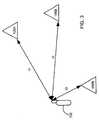
- FIG. 3depicts the geometry of a position determination using 3 DTV transmitters.
- FIG. 4depicts an implementation of a sampler for use in taking samples of received DTV signals.
- FIG. 5depicts an implementation of a noncoherent correlator for use in searching for the correlation peak of the DTV signal samples produced by the sampler of FIG. 4 .
- FIG. 6illustrates a simple example of a position location calculation for a user terminal receiving DTV signals from two separate DTV antennas.
- FIG. 7depicts the effects of a single hill on a circle of constant range for a DTV transmitter that is located at the same altitude as the surrounding land.
- FIG. 8illustrates the structure of the ATSC frame.
- FIG. 9illustrates the structure of the field synchronization segment of the ATSC frame.
- FIG. 10illustrates the structure of the data segment of the ATSC frame.
- FIG. 11shows a plot of the gain function for a filter used in producing an ATSC DTV signal.
- FIG. 12depicts an implementation of a monitor unit.
- FIG. 13illustrates one implementation for tracking in software.
- FIG. 14shows a plot of the output of the non-coherent correlator.
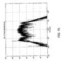
- FIG. 15displays an example spectrum for a 1 millisecond sample of the signal from a KICU channel 52 DTV broadcast from San Jose.
- FIG. 16shows the computed autocorrelation function for the in-phase and quadrature component of the resulting 6 MHz signal.
- FIG. 17shows the characteristics of the 6 MHz signal.
- FIG. 18depicts the results of a simulation of the operation of the correlator of FIG. 5 .
- DTVDigital television
- FCCFederal Communications Commission
- These new DTV signalspermit multiple standard definition TV signals or even high definition signals to be transmitted in the assigned 6 MHz channel.
- These new American Television Standards Committee (ATSC) DTV signalsare completely different from the analog NTSC TV signals, are transmitted on new 6 MHz frequency channels, and have completely new capabilities.
- ATSCAmerican Television Standards Committee
- the inventorshave recognized that the ATSC signal can be used for position location, and have developed techniques for doing so. These techniques are usable in the vicinity of ATSC DTV transmitters with a range from the transmitter much wider than the typical DTV reception range. Because of the high power of the DTV signals, these techniques can even be used indoors by handheld receivers, and thus provide a possible solution to the position location needs of the Enhanced 911 (E911) system.
- E911Enhanced 911
- the techniques disclosed hereinare also applicable to DTV signals as defined by the Digital Video Broadcasting (DVB) standard recently adopted by the European Telecommunications Standards Institute (ETSI).
- DVDDigital Video Broadcasting
- ETSIEuropean Telecommunications Standards Institute
- the techniques described hereincan be used with the scattered pilot carrier signals embedded within the DVB signal.
- the DVB scattered pilot carrier signalsare a set of 868 uniformly-spaced pilot carrier signals, each of which is frequency hopped in a chirp-like fashion over four sequentially-increasing frequencies.
- These techniquesare also applicable to DTV signals as defined by the Japanese Integrated Service Digital Broadcasting-Terrestrial (ISDB-T). These techniques are also applicable to other DTV signals, including those which transmit a known sequence of data.
- ISDB-TJapanese Integrated Service Digital Broadcasting-Terrestrial
- the DTV signalsare received from transmitters only a few miles distant, and the transmitters broadcast signals at levels up to the megawatt level.
- the DTV antennashave significant antenna gain, on the order of 14 dB. Thus there is often sufficient power to permit DTV signal reception inside buildings.
- Certain implementations of the present inventionuse only the DTV signal synchronization codes as opposed to demodulating and decoding the DTV 8-ary Vestigial Sideband Modulation (8VSB) data signal. Consequently, the DTV signal can be correlated for a period roughly a million times longer than the period of single data symbol. Thus the ability to track signals indoors at substantial range from the DTV tower is greatly expanded. Furthermore, through the use of digital signal processing it is possible to implement these new tracking techniques in a single semiconductor chip.
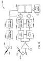
- an example implementation 100includes a user terminal 102 that communicates over an air link with a base station 104 .
- user terminal 102is a wireless telephone and base station 104 is a wireless telephone base station.
- base station 104is part of a mobile MAN (metropolitan area network) or WAN (wide area network).
- FIG. 1is used to illustrate various aspects of the invention but the invention is not limited to this implementation.
- the phrase “user termiinal”is meant to refer to any object capable of implementing the DTV position location described.
- user terminalsinclude PDAs, mobile phones, cars and other vehicles, and any object which could include a chip or software implementing DTV position location. It is not intended to be limited to objects which are “terminals” or which are operated by “users.”
- FIG. 2illustrates an operation of implementation 100 .
- User terminal 102receives DTV signals from a plurality of DTV transmitters 106 A and 106 B through 106 N (step 202 ).
- a DTV location server 110tells user terminal 102 of the best DTV channels to monitor.
- user terminal 102exchanges messages with DTV location server 110 by way of base station 104 .
- user terminal 102selects DTV channels to monitor based on the identity of base station 104 and a stored table correlating base stations and DTV channels.
- user terminal 102can accept a location input from the user that gives a general indication of the area, such as the name of the nearest city; and uses this information to select DTV channels for processing.
- user terminal 102scans available DTV channels to assemble a fingerprint of the location based on power levels of the available DTV channels. User terminal 102 compares this fingerprint to a stored table that matches known fingerprints with known locations to select DTV channels for processing.
- Each pseudo-rangerepresents the time difference (or equivalent distance) between a time of transmission from a transmitter 108 of a component of the DTV broadcast signal and a time of reception at the user terminal 102 of the component, as well as a clock offset at the user terminal.
- DTV location server 110is implemented as a general-purpose computer executing software designed to perform the operations described herein.
- DTV location serveris implemented as an ASIC (application-specific integrated circuit).
- DTV location server 110is implemented within or near base station 104 .
- the DTV signalsare also received by a plurality of monitor units 108 A through 108 N.
- Each monitor unitcan be implemented as a small unit including a transceiver and processor, and can be mounted in a convenient location such as a utility pole, DTV transmitters 106 , or base stations 104 .
- monitor unitsare implemented on satellites.
- Each monitor unit 108measures, for each of the DTV transmitters 106 from which it receives DTV signals, a time offset between the local clock of that DTV transmitter and a reference clock.
- the reference clockis derived from GPS signals. The use of a reference clock permits the determination of the time offset for each DTV transmitter 106 when multiple monitor units 108 are used, since each monitor unit 108 can determine the time offset with respect to the reference clock. Thus, offsets in the local clocks of the monitor units 108 do not affect these determinations.
- a single monitor unitreceives DTV signals from all of the same DTV transmitters as does user terminal 102 .
- the local clock of the single monitor unitfunctions as the time reference.
- each time offsetis modeled as a fixed offset.
- each measured time offsetis transmitted periodically to the DTV location server using the Internet, a secured modem connection or the like.
- the location of each monitor unit 108is determined using GPS receivers.
- DTV location server 110receives information describing the phase center (i.e., the location) of each DTV transmitter 106 from a database 112 .
- the phase center of each DTV transmitter 106is measured by using monitor units 108 at different locations to measure the phase center directly.
- the phase center of each DTV transmitter 106is measured by surveying the antenna phase center.
- DTV location server 110receives weather information describing the air temperature, atmospheric pressure, and humidity in the vicinity of user terminal 102 from a weather server 114 .
- the weather informationis available from the Internet and other sources such as NOAA.
- DTV location server 110determines tropospheric propagation velocity from the weather information using techniques such as those disclosed in B. Parkinson and J. Spilker, Jr. Global Positioning System-Theory and Applications, AIAA, Washington, D.C., 1996, Vol. 1, Chapter 17 Tropospheric Effects on GPS by J. Spilker, Jr.
- DTV location server 110can also receive from base station 104 information which identifies a general geographic location of user terminal 102 .
- the informationcan identify a cell or cell sector within which a cellular telephone is located. This information is used for ambiguity resolution, as described below.
- DTV location server 110determines a position of the user terminal based on the pseudo-ranges and a location of each of the transmitters (step 206 ).
- FIG. 3depicts the geometry of a position determination using three DTV transmitters 106 .
- DTV transmitter 106 Ais located at position (x1, y1). The range between user terminal 102 and DTV transmitter 106 A is r1.
- DTV 106 B transmitteris located at position (x2, y2).
- the range between user terminal 102 and DTV transmitter 106 Bis r2.
- DTV transmitter 106 Nis located at position (x3, y3). The range between user terminal 102 and DTV transmitter 106 N is r3.
- DTV location server 110may adjust the value of each pseudo-range according to the tropospheric propagation velocity and the time offset for the corresponding DTV transmitter 106 .
- DTV location server 110uses the phase center information from database 112 to determine the position of each DTV transmitter 106 .
- User terminal 102makes three or more pseudo-range measurements to solve for three unknowns, namely the position (x, y) and clock offset T of user terminal 102 .
- the techniques disclosed hereinare used to determine position in three dimensions such as longitude, latitude, and altitude, and can include factors such as the altitude of the DTV transmitters.
- (5) r 2
- (6) r 3
- DTV locations server 110solves these equations according to conventional well-known methods.
- the position of user terminal 102is transmitted to E911 location server 116 for distribution to the proper authorities.
- the positionis transmitted to user terminal 102 .
- user terminal 102does not compute pseudo-ranges, but rather takes measurements of the DTV signals that are sufficient to compute pseudo-range, and transmits these measurements to DTV location server 110 .
- DTV location server 110then computes the pseudo-ranges based on the measurements, and computes the position based on the pseudo-ranges, as described above.
- the position of user terminal 102is computed by user terminal 102 .
- all of the necessary informationis transmitted to user terminal 102 .
- This informationcan be transmitted to user terminal by DTV location server 110 , base station 104 , one or more DTV transmitters 106 , or any combination thereof.
- User terminal 102measures the pseudo-ranges and solves the simultaneous equations as described above. This implementation is now described.
- User terminal 102receives the time offset between the local clock of each DTV transmitter and a reference clock. User terminal 102 also receives information describing the phase center of each DTV transmitter 106 from a database 112 .
- User terminal 102receives the tropospheric propagation velocity computed by DTV locations server 110 .
- user terminal 102receives weather information describing the air temperature, atmospheric pressure, and humidity in the vicinity of user terminal 102 from a weather server 114 . and determines tropospheric propagation velocity from the weather information using conventional techniques.
- User terminal 102can also receive from base station 104 information which identifies the rough location of user terminal 102 .
- the informationcan identify a cell or cell sector within which a cellular telephone is located. This information is used for ambiguity resolution, as described below.
- User terminal 102receives DTV signals from a plurality of DTV transmitters 106 and determines a pseudo-range between the user terminal 102 and each DTV transmitter 106 . User terminal 102 then determines its position based on the pseudo-ranges and the phase centers of the transmitters.
- the position of user terminal 102can be determined using the two DTV transmitters and the offset T computed during a previous position determination.
- the values of Tcan be stored or maintained according to conventional methods.
- base station 104determines the clock offset of user terminal 102 . In this implementation, only two DTV transmitters are required for position determination. Base station 104 transmits the clock offset T to DTV location server 110 , which then determines the position of user terminal 102 from the pseudo-range computed for each of the DTV transmitters.
- GPSis used to augment the position determination.
- FIG. 4depicts an implementation 400 of a sampler for use in taking samples of received DTV signals.
- sampler 400is implemented within user terminal 102 .
- sampler 400is implemented within monitor units 108 .
- the sampling rateshould be sufficiently high to obtain an accurate representation of the DTV signal, as would be apparent to one skilled in the art.
- Sampler 400receives a DTV signal 402 at an antenna 404 .
- a radio frequency (RF) amp/filter 406amplifies and filters the received DTV signal.
- a local oscillator clock 416 and mixers 408 I and 408 Qdownconvert the signal to produce in-phase (I) and quadrature (Q) samples, respectively.
- the I and Q samplesare respectively filtered by low-pass filters (LPF) 410 I and 410 Q.
- An analog-to-digital converter (ADC) 412converts the I and Q samples to digital form.
- the digital I and Q samplesare stored in a memory 414 .
- FIG. 5depicts an implementation 500 of a noncoherent correlator for use in searching for the correlation peak of the DTV signal samples produced by sampler 400 .
- correlator 500is implemented within user terminal 102 .
- correlator 500is implemented within monitor units 108 .
- Correlator 500retrieves the I and Q samples of a DTV signal from memory 414 . Correlator 500 processes the samples at intermediate frequency (IF). Other implementations process the samples in analog or digital form, and can operate at intermediate frequency (IF) or at baseband.
- IFintermediate frequency
- a code generator 502generates a code sequence.
- the code sequenceis a raised cosine waveform.
- the code sequencecan be any known digital sequence in the ATSC frame.
- the codeis a synchronization code.
- the synchronization codeis a Field Synchronization Segment within an ATSC data frame.
- the synchronization codeis a Synchronization Segment within a Data Segment within an ATSC data frame.
- the synchronization codeincludes both the Field Synchronization Segment within an ATSC data frame and the Synchronization Segments within the Data Segments within an ATSC data frame.
- Other components of the DTV signalsuch as pilot, symbol clock, or carrier, can be used for position location.
- Mixers 504 I and 504 Qrespectively combine the I and Q samples with the code generated by code generator 502 .
- the outputs of mixers 504 I and 504 Qare respectively filtered by filters 506 I and 506 Q and provided to summer 507 .
- the sumis provided to square law device 508 .
- Filter 509performs an envelope detection for non-coherent correlation, according to conventional methods.
- Comparator 510compares the correlation output to a predetermined threshold. If the correlation output falls below the threshold, search control 512 causes summer 514 to add additional pulses to the clocking waveform produced by clock 516 , thereby advancing the code generator by one symbol time, and the process repeats.
- the clocking waveformhas a nominal clock rate of 10.76 MHz, matching the clock rate or symbol rate the received DTV signals.
- the processis done.
- the time offset that produced the correlation outputis used as the pseudo-range for that DTV transmitter 106 .
- the user terminal local oscillatoris often of relatively poor stability in frequency. This instability affects two different receiver parameters. First, it causes a frequency offset in the receiver signal. Second, it causes the received bit pattern to slip relative to the symbol rate of the reference clock. Both of these effects can limit the integration time of the receiver and hence the processing gain of the receiver. The integration time can be increased by correcting the receiver reference clock. In one implementation a delay lock loop automatically corrects for the receiver clock.
- a NCO (numerically controlled oscillator) 518adjusts the clock frequency of the receiver to match that of the incoming received signal clock frequency and compensate for drifts and frequency offsets of the local oscillator in user terminal 102 . Increased accuracy of the clock frequency permits longer integration times and better performance of the receiver correlator.
- the frequency control input of NCO 518can be derived from several possible sources, a receiver symbol clock rate synchronizer, tracking of the ATSC pilot carrier, or other clock rate discriminator techniques installed in NCO 518 .
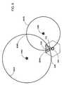
- FIG. 6illustrates a simple example of a position location calculation for a user terminal 102 receiving DTV signals from two separate DTV antennas 106 A and 106 B. Circles of constant range 602 A and 602 B are drawn about each of transmit antennas 106 A and 106 B, respectively.
- the position for a user terminalincluding correction for the user terminal clock offset, is then at one of the intersections 604 A and 604 B of the two circles 602 A and 602 B.
- the ambiguityis resolved by noting that base station 104 can determine in which sector 608 of its footprint (that is, its coverage area) 606 the user terminal is located. Of course if there are more than two DTV transmitters in view, the ambiguity can be resolved by taking the intersection of three circles.
- user terminal 102can accept an input from the user that gives a general indication of the area, such as the name of the nearest city.
- user terminal 102scans available DTV channels to assemble a fingerprint of the location. User terminal 102 compares this fingerprint to a stored table that matches known fingerprints with known locations to identify the current location of user terminal 102 .
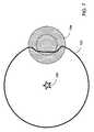
- the position location calculationincludes the effects of ground elevation.
- the circles of constant rangeare distorted.
- FIG. 7depicts the effects of a single hill 704 on a circle of constant range 702 for a DTV transmitter 106 that is located at the same altitude as the surrounding land.
- the computations of user positionare easily made by a simple computer having as its database a terrain topographic map which allows the computations to include the effect of user altitude on the surface of the earth, the geoid. This calculation has the effect of distorting the circles of constant range as shown in FIG. 7 .
- the current ATSC signalis described in “ATSC Digital Television Standard and Amendment No. 1,” Mar. 16, 2000, by the Advanced Television Systems Committee.
- the ATSC signaluses 8-ary Vestigial Sideband Modulation (8VSB).
- the symbol rate of the ATSC signalis 10.762237 MHz, which is derived from a 27.000000 MHz clock.
- the structure 800 of the ATSC frameis illustrated in FIG. 8 .
- the frame 800consists of a total of 626 segments, each with 832 symbols, for a total of 520832 symbols.
- the structure 900 of the field synchronization segmentis illustrated in FIG. 9 .
- the two field synchronization segments 900 in a frame 800differ only to the extent that the middle set of 63 symbols are inverted in the second field synchronization segment.
- the structure 1000 of the data segmentis illustrated in FIG. 10 .
- the first four symbols of data segment 1000(which are ⁇ 1, 1, 1, ⁇ 1) are used for segment synchronization.
- the other 828 symbols in data segment 1000carry data. Since the modulation scheme is 8VSB, each symbol carries 3 bits of coded data. A rate 2 ⁇ 3 coding scheme is used.
- Implementations of the inventioncan be extended to use future enhancements to DTV signals.
- the ATSC signal specificationallows for a high rate 16VSB signal.
- the 16VSB signalhas the same field synch pattern as the 8VSB signal. Therefore, a single implementation of the present invention can be designed to work equally well with both the 8VSB and the 16VSB signal.
- the 8VSB signalis constructed by filtering.
- the in-phase segment of the symbol pulsehas a raised-cosine characteristic, as described in J. G. Proakis, Digital Communications, McGraw-Hill, 3 rd edition, 1995.
- the signalis filtered so that only a small portion of the lower sideband remains.
- FIG. 12depicts an implementation 1200 of monitor unit 108 .
- An antenna 1204receives GPS signals 1202 .
- a GPS time transfer unit 1206develops a master clock signal based on the GPS signals.
- a NCO (numerically controlled oscillator) field synchronization timer 1208 Adevelops a master synchronization signal based on the master clock signal.
- the master synchronization signalcan include one or both of the ATSC segment synchronization signal and the ATSC field synchronization signal.
- the NCO field synchronization timers 1208 A in all of the monitor units 108are synchronized to a base date and time.
- a single monitor unit 108receives DTV signals from all of the same DTV transmitters that user terminal 102 does, it is not necessary to synchronize that monitor unit 108 with any other monitor unit for the purposes of determining the position of user terminal 102 . Such synchronization is also unnecessary if all of the monitor stations 108 , or all of the DTV transmitters, are synchronized to a common clock.
- a DTV antenna 1212receives a plurality of DTV signals 1210 . In another implementation, multiple DTV antennas are used.
- An amplifier 1214amplifies the DTV signals.
- One or more DTV tuners 1216 A through 1216 Neach tunes to a DTV channel in the received DTV signals to produce a DTV channel signal.
- Each of a plurality of NCO field synchronization timers 1208 B through 1208 Mreceives one of the DTV channel signals.
- Each of NCO field synchronization timers 1208 B through 1208 Mextracts a channel synchronization signal from a DTV channel signal.
- the channel synchronization signalcan include one or both of the ATSC segment synchronization signal and the ATSC field synchronization signal. Note that the pilot signal and symbol clock signal within the DTV signal can be used as acquisition aids.
- Each of a plurality of summers 1218 A through 1218 Ngenerates a clock offset between the master synchronization signal and one of the channel synchronization signals.
- Processor 1220formats and sends the resulting data to DTV location server 110 .
- this dataincludes, for each DTV channel measured, the identification number of the DTV transmitter, the DTV channel number, the antenna phase center for the DTV transmitter, and the clock offset.
- This datacan be transmitted by any of a number of methods including air link and the Internet.
- the datais broadcast in spare MPEG packets on the DTV channel itself.
- Multipath effectscan be mitigated by selecting the earliest correlation peak.
- FIG. 13illustrates one implementation 1300 for tracking in software.
- An antenna 1302receives a DTV signal.
- Antenna 1302can be a magnetic dipole or any other type of antenna capable of receiving DTV signals.
- a bandpass filter 1304passes the entire DTV signal spectrum to an LNA 1306 .
- filter 1304is a tunable bandpass filter that passes the spectrum for a particular DTV channel under the control of a digital signal processor (DSP) 1314 .
- DSPdigital signal processor
- a low-noise amplifier (LNA) 1306amplifies and passes the selected signal to a DTV channel selector 1308 .
- DTV channel selector 1308selects a particular DTV channel under the control of DSP 1314 , and filters and downconverts the selected channel signal from UHF (ultra-high frequency) to IF (intermediate frequency) according to conventional methods.
- An amplifier (AMP) 1310amplifies the selected IF channel signal.
- An analog-to-digital converter and sampler (A/D) 1312produces digital samples of the DTV channel signal s(t) and passes these samples to DSP 1314 .
- DTV channel signal by DSP 1314is described for a coherent software receiver.
- a nominal offset frequency for the downconverted sampled signalis assumed. If this signal is downconverted to baseband, the nominal offset is 0 Hz.
- the processgenerates the complete autocorrelation function based on samples of a signal s(t). The process may be implemented far more efficiently for a low duty factor signal. Let T i be the period of data sampled, ⁇ in be the nominal offset of the sampled incident signal, and let ⁇ offset be the largest possible offset frequency, due to Doppler shift and oscillator frequency drift.
- the processimplements the pseudocode listed below.
- R store ( ⁇ )Upon exit from the process, R store ( ⁇ ) will store the correlation between the incident signal s(t) and the complex code signal s code (t). R store ( ⁇ ) may be further refined by searching over smaller steps of ⁇ . The initial step size for ⁇ must be less then half the Nyquist ⁇ ⁇ rate ⁇ ⁇ 2 ⁇ ⁇ T i .
- the time offset ⁇ that produces the maximum correlation outputis used as the pseudo-range.
- the time offset ⁇ that produces the maximum correlation outputis used as the pseudo-range.
- the output of the non-coherent correlatoris illustrated in FIG. 14 .
- the upper plotshows the correlation peak for an interval of roughly 8 ⁇ 10 ⁇ 5 seconds.
- the upper plotshows the effective 3 MHz bandwidth of the correlation peak.
- FIG. 15displays an example spectrum for a 1 millisecond sample of the signal from a KICU channel 52 DTV broadcast from San Jose.
- the signalwas downconverted to a center frequency of 27 MHz, which corresponds to a digital frequency of 0.54 for a sampling rate of 100 mega-samples per second.
- the signalwas digitally bandpass filtered to a bandwidth of 6 MHz.
- the computed autocorrelation function for the in-phase and quadrature component of the resulting 6 MHz signalis illustrated in FIG. 16 . Note that this is the autocorrelation for only the 4 data synchronization symbols at the beginning of each segment.
- FIG. 17displays a portion of the autocorrelation peak for the in-phase channel. From the smoothness of the curve, one can see that the signal-to-noise ratio is high. In addition, the curvature of the peak indicates the high signal bandwidth which makes this signal robust to multipath.
- FIG. 18depicts the results of a simulation of the operation of correlator 500 .
- the simulationwas conducted using Mathematica software produced by Wolfram Research.
- the simulation inputis the digital I and Q samples stored in a memory 414 by sampler 400 .
- FIG. 18shows the noncoherent correlation result for symbol-synchronous sampling at a 10.76 MHz complex sample rate and an integration time of 242 milliseconds or 10 fields.
- the simulationis a worst case where the samples are offset by 1 ⁇ 2 symbol or 0.05 microseconds.
- the simulationalso includes Gaussian noise and a signal-to-noise ratio (SNR) in the 6 MHz bandwidth of ⁇ 27 dB. With a phase offset of the sampling this result degrades by 2 dB but clearly the performance would still be excellent.
- SNRsignal-to-noise ratio
- Normal DTV receptionrequires a SNR of approximately +18 dB.
- a time-gated delay lock loop (DLL)will automatically synchronize its clock to that of the received signal and produce the same result.
- DLLtime-gated delay lock loop
- the inventioncan be implemented in digital electronic circuitry, or in computer hardware, firmware, software, or in combinations thereof.
- Apparatus of the inventioncan be implemented in a computer program product tangibly embodied in a machine-readable storage device for execution by a programmable processor; and method steps of the invention can be performed by a programmable processor executing a program of instructions to perform functions of the invention by operating on input data and generating output.
- the inventioncan be implemented advantageously in one or more computer programs that are executable on a programmable system including at least one programmable processor coupled to receive data and instructions from, and to transmit data and instructions to, a data storage system, at least one input device, and at least one output device.
- Each computer programcan be implemented in a high-level procedural or object-oriented programming language, or in assembly or machine language if desired; and in any case, the language can be a compiled or interpreted language.
- Suitable processorsinclude, by way of example, both general and special purpose microprocessors.
- a processorwill receive instructions and data from a read-only memory and/or a random access memory.
- a computerwill include one or more mass storage devices for storing data files; such devices include magnetic disks, such as internal hard disks and removable disks; magneto-optical disks; and optical disks.
- Storage devices suitable for tangibly embodying computer program instructions and datainclude all forms of non-volatile memory, including by way of example semiconductor memory devices, such as EPROM, EEPROM, and flash memory devices; magnetic disks such as internal hard disks and removable disks; magneto-optical disks; and CD-ROM disks. Any of the foregoing can be supplemented by, or incorporated in, ASICs (application-specific integrated circuits).
- semiconductor memory devicessuch as EPROM, EEPROM, and flash memory devices
- magnetic diskssuch as internal hard disks and removable disks
- magneto-optical disksmagneto-optical disks
- CD-ROM disksCD-ROM disks
- Implementations of the present inventionexploit the low duty factor of the DTV signal in many ways.
- one implementationemploys a time-gated delay-lock loop (DLL) such as that disclosed in J. J. Spilker, Jr., Digital Communications by Satellite, Prentice-Hall, Englewood Cliffs N.J., 1977, Chapter 18-6.
- DLLtime-gated delay-lock loop
- Other implementationsemploy variations of the DLL, including coherent, noncoherent, and quasi-coherent DLLs, such as those disclosed in J. J. Spilker, Jr., Digital Communications by Satellite, Prentice-Hall, Englewood Cliffs N.J., 1977, Chapter 18 and B. Parkinson and J.
- DTV location server 110employs redundant signals available at the system level, such as psuedoranges available from the DTV transmitters, making additional checks to validate each DTV channel and pseudo-range, and to identify DTV channels that are erroneous.
- redundant signals available at the system levelsuch as psuedoranges available from the DTV transmitters, making additional checks to validate each DTV channel and pseudo-range, and to identify DTV channels that are erroneous.
- RAIMreceiver autonomous integrity monitoring
Landscapes
- Engineering & Computer Science (AREA)
- Radar, Positioning & Navigation (AREA)
- Remote Sensing (AREA)
- Physics & Mathematics (AREA)
- General Physics & Mathematics (AREA)
- Multimedia (AREA)
- Signal Processing (AREA)
- Databases & Information Systems (AREA)
- Automation & Control Theory (AREA)
- Computer Graphics (AREA)
- Computer Networks & Wireless Communication (AREA)
- Position Fixing By Use Of Radio Waves (AREA)
Abstract
Description
Offset=a+b(t−T)+c(t−T)2 (1)
that can be described by a, b, c, and T. In either implementation, each measured time offset is transmitted periodically to the DTV location server using the Internet, a secured modem connection or the like. In one implementation, the location of each monitor unit108 is determined using GPS receivers.
pr1=r1+T (2)
pr2=r2+T (3)
pr3=r3+T (4)
The three ranges can be expressed as
r1=|X−X1| (5)
r2=|X−X2| (6)
r3=|X−X3| (7)
where X represents the two-dimensional vector position (x, y) of user terminal, X1 represents the two-dimensional vector position (x1, y1) of
where T is the symbol period
and β=0.5762. This signal has a frequency characteristic
from which it is clear that the one-sided bandwidth of the signal is (1+β)10.762237 MHz=5.38 MHz+0.31 MHz. In order to create a VSB signal from this in-phase pulse, the signal is filtered so that only a small portion of the lower sideband remains. This filtering can be described as:
Pν(f)=P(f)(U(f)−Hα(f)) (11)
where
where Hα(f) is a filter designed to leave a vestigal remainder of the lower sideband. A plot of the gain function for Hα(f) is shown in FIG.11. The filter satisfies the characteristics Hα(−f)=−Hα(f) and Hα(f)=0, f>α.
where {hacek over (P)}(f)=−jsgn(f)P(f) is the Hilbert transform of P(f). The VSB pulse may be represented as
and the baseband pulse signal
where pνi(t) is the in-phase component, pνq(t) is the quadrature component, and
where Cnis the 8-level data signal.
- Rmax=0
- Create a complex code signal
scode(t)=Σ{overscore (C)}n{pνi(t−nTi)+jpνq(t−nTi)
where {overscore (C)}nis zero for all symbols corresponding to data signals and non-zero for all symbols corresponding to synchronization signals. - Create a complex mixing signal
smix(t)=cos(ωt)+jsin(ωt),t=[0 . . . Ti] - Combine the incident signal s(t) and the mixing signal smix(t)
scomb(t)=s(t)smix(t) - Compute the correlation function R(τ)=scode*scomb(τ)
- If maxr|R(τ)|>Rmax,
Rmax←maxr|R(τ)|,Rstore(τ)=R(τ) - Next ω
- Create the in-phase and quadrature code signals
- ci(t)=Σ{overscore (C)}npνq(t−nTi), cq(t)=Σ{overscore (C)}npνq(t−nTi) where the sum is over n, {overscore (C)}nis zero for all symbols corresponding to data signals and non-zero for all symbols corresponding to synchronization signals. Note that cihas autocorrelation Ri, cqhas autocorrelation Rq, and that their cross-correlation is Rij.
- For τ=0 to Tperstep Tsampwhere Tperis the period of the code being used, and Tsampis the sample interval
- Create a reference code mixing signal
smix(t)=ci(t+τ)cos(ωt+υt+φ)+cq(t+τ)sin(ωt+υt+φ) - where ω is the nominal IF frequency of the incident signal, υ is the frequency offset of the mixing signal relative to the incident signal, and φ is the phase offset of the mixing signal from the incident signal.
- Combine the incident signal s(t) and the reference code mixing signal smix(t). scomb(t)=s(t)smix(t)
- Low-pass filter scomb(t) to generate sfilt(t) such that the expected value of sfilt(t) is given by E[sfilt(t)]=2Ri(τ)cos(υt+φ)+2Riq(τ)sin(υt+φ) where we have used that fact that Ri(τ)=−Rq(τ)
- Perform envelope detection on sfilt(t) (for example, by squaring and filtering) to generate the non-coherent correlation: z(τ)=2[Ri(τ)2+Riq(τ)2]
- Next τ
- Create a reference code mixing signal
Claims (114)
Priority Applications (12)
| Application Number | Priority Date | Filing Date | Title |
|---|---|---|---|
| US10/210,847US6861984B2 (en) | 2001-02-02 | 2002-07-31 | Position location using broadcast digital television signals |
| US10/290,984US6952182B2 (en) | 2001-08-17 | 2002-11-08 | Position location using integrated services digital broadcasting—terrestrial (ISDB-T) broadcast television signals |
| US10/658,356US6914560B2 (en) | 2001-08-17 | 2003-09-09 | Position location using broadcast digital television signals comprising pseudonoise sequences |
| US10/675,422US6970132B2 (en) | 2001-02-02 | 2003-09-30 | Targeted data transmission and location services using digital television signaling |
| US10/741,431US7042396B2 (en) | 2001-08-17 | 2003-12-18 | Position location using digital audio broadcast signals |
| US10/756,814US20040201779A1 (en) | 2001-02-02 | 2004-01-13 | Symbol clock recovery for the ATSC digital television signal |
| US10/787,058US6963306B2 (en) | 2001-02-02 | 2004-02-24 | Position location and data transmission using pseudo digital television transmitters |
| US10/867,577US20050066373A1 (en) | 2001-02-02 | 2004-06-14 | Position location using broadcast digital television signals |
| US11/068,570US20050251844A1 (en) | 2001-02-02 | 2005-02-28 | Blind correlation for high precision ranging of coded OFDM signals |
| US11/284,800US8102317B2 (en) | 2001-02-02 | 2005-11-22 | Location identification using broadcast wireless signal signatures |
| US12/741,346US8754807B2 (en) | 2001-02-02 | 2009-06-02 | Time, frequency, and location determination for femtocells |
| US12/693,283US8677440B2 (en) | 2001-02-02 | 2010-01-25 | Position determination using ATSC-M/H signals |
Applications Claiming Priority (10)
| Application Number | Priority Date | Filing Date | Title |
|---|---|---|---|
| US26567501P | 2001-02-02 | 2001-02-02 | |
| US28126901P | 2001-04-03 | 2001-04-03 | |
| US28127001P | 2001-04-03 | 2001-04-03 | |
| US29381301P | 2001-05-25 | 2001-05-25 | |
| US29381201P | 2001-05-25 | 2001-05-25 | |
| US29364601P | 2001-05-25 | 2001-05-25 | |
| US88715801A | 2001-06-21 | 2001-06-21 | |
| US30926701P | 2001-07-31 | 2001-07-31 | |
| US34498801P | 2001-12-20 | 2001-12-20 | |
| US10/210,847US6861984B2 (en) | 2001-02-02 | 2002-07-31 | Position location using broadcast digital television signals |
Related Parent Applications (5)
| Application Number | Title | Priority Date | Filing Date |
|---|---|---|---|
| US88715801AContinuation | 2001-02-02 | 2001-06-21 | |
| US88715801AContinuation-In-Part | 2001-02-02 | 2001-06-21 | |
| US10/209,578Continuation-In-PartUS6753812B2 (en) | 2001-02-02 | 2002-07-31 | Time-gated delay lock loop tracking of digital television signals |
| US10/675,422ContinuationUS6970132B2 (en) | 2001-02-02 | 2003-09-30 | Targeted data transmission and location services using digital television signaling |
| US12/741,346ContinuationUS8754807B2 (en) | 2001-02-02 | 2009-06-02 | Time, frequency, and location determination for femtocells |
Related Child Applications (10)
| Application Number | Title | Priority Date | Filing Date |
|---|---|---|---|
| US10/232,142Continuation-In-PartUS6717547B2 (en) | 2001-02-02 | 2002-08-29 | Position location using broadcast television signals and mobile telephone signals |
| US10/290,984Continuation-In-PartUS6952182B2 (en) | 2001-02-02 | 2002-11-08 | Position location using integrated services digital broadcasting—terrestrial (ISDB-T) broadcast television signals |
| US10/658,356Continuation-In-PartUS6914560B2 (en) | 2001-08-17 | 2003-09-09 | Position location using broadcast digital television signals comprising pseudonoise sequences |
| US10/675,422ContinuationUS6970132B2 (en) | 2001-02-02 | 2003-09-30 | Targeted data transmission and location services using digital television signaling |
| US10/675,422Continuation-In-PartUS6970132B2 (en) | 2001-02-02 | 2003-09-30 | Targeted data transmission and location services using digital television signaling |
| US10/741,431Continuation-In-PartUS7042396B2 (en) | 2001-02-02 | 2003-12-18 | Position location using digital audio broadcast signals |
| US10/756,814Continuation-In-PartUS20040201779A1 (en) | 2001-02-02 | 2004-01-13 | Symbol clock recovery for the ATSC digital television signal |
| US10/787,058Continuation-In-PartUS6963306B2 (en) | 2001-02-02 | 2004-02-24 | Position location and data transmission using pseudo digital television transmitters |
| US10/867,577Continuation-In-PartUS20050066373A1 (en) | 2001-02-02 | 2004-06-14 | Position location using broadcast digital television signals |
| US10/867,577ContinuationUS20050066373A1 (en) | 2001-02-02 | 2004-06-14 | Position location using broadcast digital television signals |
Publications (2)
| Publication Number | Publication Date |
|---|---|
| US20030052822A1 US20030052822A1 (en) | 2003-03-20 |
| US6861984B2true US6861984B2 (en) | 2005-03-01 |
Family
ID=27578760
Family Applications (1)
| Application Number | Title | Priority Date | Filing Date |
|---|---|---|---|
| US10/210,847Expired - LifetimeUS6861984B2 (en) | 2001-02-02 | 2002-07-31 | Position location using broadcast digital television signals |
Country Status (1)
| Country | Link |
|---|---|
| US (1) | US6861984B2 (en) |
Cited By (40)
| Publication number | Priority date | Publication date | Assignee | Title |
|---|---|---|---|---|
| US20020144294A1 (en)* | 2001-02-02 | 2002-10-03 | Matthew Rabinowitz | Position location using terrestrial digital video broadcast television signals |
| US20020184653A1 (en)* | 2001-02-02 | 2002-12-05 | Pierce Matthew D. | Services based on position location using broadcast digital television signals |
| US20020199196A1 (en)* | 2001-06-21 | 2002-12-26 | Matthew Rabinowitz | Position location using global positioning signals augmented by broadcast television signals |
| US20040165066A1 (en)* | 2003-02-24 | 2004-08-26 | Rosum Corporation | Method and system for generating reference signals with improved correlation characteristics for accurate time of arrival or position determination |
| US20050117070A1 (en)* | 2003-01-30 | 2005-06-02 | Yiyan Wu | Transmitter identification system |
| US20050251844A1 (en)* | 2001-02-02 | 2005-11-10 | Massimiliano Martone | Blind correlation for high precision ranging of coded OFDM signals |
| US20050289589A1 (en)* | 2004-06-29 | 2005-12-29 | Larri Vermola | System and method for location-appropriate service listings |
| US20070050824A1 (en)* | 2001-02-02 | 2007-03-01 | Andy Lee | Location identification using broadcast wireless signal signatures |
| US20070069952A1 (en)* | 2005-09-27 | 2007-03-29 | Fuyun Ling | Position location using phase-adjusted transmitters |
| US20070072621A1 (en)* | 2005-09-27 | 2007-03-29 | Mukkavilli Krishna K | Position location using transmitters with timing offset |
| US20070069953A1 (en)* | 2005-09-27 | 2007-03-29 | Fuyun Ling | Position location using transmitters with timing offset and phase adjustment |
| US20070115171A1 (en)* | 2005-11-18 | 2007-05-24 | Rahman Mohammad A | Methods and apparatus to detect and correct integrity failures in satellite positioning system receivers |
| US20070121555A1 (en)* | 2005-11-08 | 2007-05-31 | David Burgess | Positioning using is-95 cdma signals |
| US20070182633A1 (en)* | 2001-02-02 | 2007-08-09 | Rosum Corporation | Monitor Units for Television Signals |
| US20070296632A1 (en)* | 2006-06-22 | 2007-12-27 | Guttorm Opshaug | Psuedo Television Transmitters for Position Location |
| US20080007398A1 (en)* | 2006-07-05 | 2008-01-10 | General Electric Company | System and method for tracking assets |
| US20080040029A1 (en)* | 1997-10-22 | 2008-02-14 | Intelligent Technologies International, Inc. | Vehicle Position Determining System and Method |
| US7388541B1 (en) | 2005-07-25 | 2008-06-17 | Chun Yang | Self-calibrating position location using periodic codes in broadcast digital transmissions |
| US7498873B2 (en) | 2005-11-02 | 2009-03-03 | Rosom Corporation | Wide-lane pseudorange measurements using FM signals |
| US20090070847A1 (en)* | 2007-07-06 | 2009-03-12 | Rosum Corporation | Positioning with Time Sliced Single Frequency Networks |
| US20090160646A1 (en)* | 2007-12-20 | 2009-06-25 | General Electric Company | System and method for monitoring and tracking inventories |
| US20090175379A1 (en)* | 2007-12-12 | 2009-07-09 | Rosum Corporation | Transmitter Identification For Wireless Signals Having A Digital Audio Broadcast Physical Layer |
| US20090217333A1 (en)* | 2008-02-27 | 2009-08-27 | Song-Lin Young | Method and system for discovering vacant DTV channels using DHCP server location |
| US20100123622A1 (en)* | 2008-11-17 | 2010-05-20 | Neil Harper | System and method for determining the location of a mobile device |
| US7737893B1 (en) | 2006-06-28 | 2010-06-15 | Rosum Corporation | Positioning in a single-frequency network |
| US20100149031A1 (en)* | 2008-12-12 | 2010-06-17 | Andrew Llc | System and method for determining forged radio frequency measurements |
| US7792156B1 (en) | 2008-01-10 | 2010-09-07 | Rosum Corporation | ATSC transmitter identifier signaling |
| US20110102264A1 (en)* | 2009-11-04 | 2011-05-05 | Electronics And Telecommunications Research Institute | Apparatus and method for detecting interior position using digital broadcasting signal |
| US8063825B1 (en)* | 2009-05-07 | 2011-11-22 | Chun Yang | Cooperative position location via wireless data link using broadcast digital transmissions |
| US8106828B1 (en) | 2005-11-22 | 2012-01-31 | Trueposition, Inc. | Location identification using broadcast wireless signal signatures |
| US8125389B1 (en) | 2008-10-20 | 2012-02-28 | Trueposition, Inc. | Doppler-aided positioning, navigation, and timing using broadcast television signals |
| US8149168B1 (en) | 2006-01-17 | 2012-04-03 | Trueposition, Inc. | Position determination using wireless local area network signals and television signals |
| US8164514B1 (en) | 2009-05-07 | 2012-04-24 | Chun Yang | Method and apparatus for fusing referenced and self-contained displacement measurements for positioning and navigation |
| US8179318B1 (en) | 2005-09-28 | 2012-05-15 | Trueposition, Inc. | Precise position determination using VHF omni-directional radio range signals |
| US8233091B1 (en) | 2007-05-16 | 2012-07-31 | Trueposition, Inc. | Positioning and time transfer using television synchronization signals |
| US8253627B1 (en) | 2009-02-13 | 2012-08-28 | David Burgess | Position determination with NRSC-5 digital radio signals |
| US8677440B2 (en) | 2001-02-02 | 2014-03-18 | Trueposition, Inc. | Position determination using ATSC-M/H signals |
| US8682341B1 (en) | 2006-11-22 | 2014-03-25 | Trueposition, Inc. | Blind identification of single-frequency-network transmitters |
| US8754807B2 (en) | 2001-02-02 | 2014-06-17 | Trueposition, Inc. | Time, frequency, and location determination for femtocells |
| DE102014224797A1 (en) | 2014-12-03 | 2016-06-09 | Fraunhofer-Gesellschaft zur Förderung der angewandten Forschung e.V. | Position determination of sensor nodes of a sensor network |
Families Citing this family (9)
| Publication number | Priority date | Publication date | Assignee | Title |
|---|---|---|---|---|
| US6734820B2 (en)* | 2002-05-13 | 2004-05-11 | Honeywell International Inc. | Methods and apparatus for conversion of radar return data |
| WO2005062681A1 (en) | 2003-12-08 | 2005-07-07 | Thomson Licensing | System and method for applying power to high intensity discharge lamps |
| US8339317B2 (en)* | 2005-06-28 | 2012-12-25 | Sony Ericsson Mobile Communications Ab | Methods, systems and devices for determining the location of a mobile device based on simulcast communication signals |
| KR20080068833A (en)* | 2005-11-04 | 2008-07-24 | 톰슨 라이센싱 | Apparatus and Method for Sensing a Low Signal-to-Noise Ratio ATSC Signal |
| CN101370469A (en)* | 2005-12-16 | 2009-02-18 | 荷兰联合利华有限公司 | Hair treatment compositions |
| CN102104837B (en)* | 2010-12-13 | 2013-11-27 | 北京邮电大学 | A positioning method and device based on mobile broadcasting |
| CN102076003B (en)* | 2010-12-13 | 2014-01-29 | 北京邮电大学 | A mobile broadcast signal demodulation chip for positioning |
| US20140375505A1 (en)* | 2013-06-24 | 2014-12-25 | Trueposition, Inc. | Positioning Using DTV Broadcast Signaling |
| CN111323803B (en)* | 2018-12-14 | 2023-07-04 | 深圳市中兴微电子技术有限公司 | Wireless signal processing method, device and terminal |
Citations (27)
| Publication number | Priority date | Publication date | Assignee | Title |
|---|---|---|---|---|
| JPS58129277A (en) | 1982-01-28 | 1983-08-02 | Japan Radio Co Ltd | Radio navigation device of hyperbola system |
| US4555707A (en) | 1982-08-27 | 1985-11-26 | Connelly Will A | Television pulsed navigation system |
| US4652884A (en) | 1984-07-20 | 1987-03-24 | Deutsche Forschungs-Und Versuchsanstalt Fur Luft-Und Raumfahrt E.V. | Satellite navigational system and method |
| US4894662A (en) | 1982-03-01 | 1990-01-16 | Western Atlas International, Inc. | Method and system for determining position on a moving platform, such as a ship, using signals from GPS satellites |
| GB2222922A (en) | 1988-06-16 | 1990-03-21 | Spectronics Micro Syst Ltd | Vehicle location system |
| US5045861A (en) | 1987-08-10 | 1991-09-03 | The Lynxvale - Cril Partnership | Navigation and tracking system |
| GB2254508A (en) | 1991-04-02 | 1992-10-07 | James Collier Mitchinson | Vehicle location determining system |
| US5157686A (en) | 1990-05-24 | 1992-10-20 | Cylink Corporation | Method and apparatus for the modulation of spread spectrum radio signals |
| US5166952A (en) | 1990-05-24 | 1992-11-24 | Cylink Corporation | Method and apparatus for the reception and demodulation of spread spectrum radio signals |
| US5323322A (en) | 1992-03-05 | 1994-06-21 | Trimble Navigation Limited | Networked differential GPS system |
| US5398034A (en) | 1993-03-29 | 1995-03-14 | Stanford Telecommunications, Inc. | Vector delay lock loop processing of radiolocation transmitter signals |
| US5481316A (en) | 1990-11-05 | 1996-01-02 | Samsung Electronics Co., Ltd. | System, apparatus and method for canceling televison ghost signals |
| US5504492A (en) | 1994-08-01 | 1996-04-02 | Honeywell Inc. | Look ahead satellite positioning system position error bound monitoring system |
| US5510801A (en) | 1994-03-01 | 1996-04-23 | Stanford Telecommunications, Inc. | Location determination system and method using television broadcast signals |
| US5774829A (en) | 1995-12-12 | 1998-06-30 | Pinterra Corporation | Navigation and positioning system and method using uncoordinated beacon signals in conjunction with an absolute positioning system |
| US5920284A (en) | 1996-09-30 | 1999-07-06 | Qualcomm Incorporated | Ambiguity resolution for ambiguous position solutions using satellite beams |
| US5952958A (en) | 1996-04-05 | 1999-09-14 | Discovision Associates | Positioning system and method |
| US5953311A (en) | 1997-02-18 | 1999-09-14 | Discovision Associates | Timing synchronization in a receiver employing orthogonal frequency division multiplexing |
| US6078284A (en) | 1996-09-30 | 2000-06-20 | Qualcomm Incorporated | Passive position determination using two low-earth orbit satellites |
| US6094168A (en) | 1995-09-19 | 2000-07-25 | Cambridge Positioning Systems Ltd. | Position determining system |
| US6107959A (en) | 1996-09-30 | 2000-08-22 | Qualcomm Incorporated | Positioning determination using one low-Earth orbit satellite |
| US6137441A (en) | 1998-09-09 | 2000-10-24 | Qualcomm Incorporated | Accurate range and range rate determination in a satellite communications system |
| US6317500B1 (en) | 1995-04-28 | 2001-11-13 | Trimble Navigation Limited | Method and apparatus for location-sensitive decryption of an encrypted signal |
| US6374177B1 (en) | 2000-09-20 | 2002-04-16 | Motorola, Inc. | Method and apparatus for providing navigational services in a wireless communication device |
| US6373432B1 (en) | 1997-03-21 | 2002-04-16 | The Board Of Trustees Of The Leland Stanford Junior University | System using leo satellites for centimeter-level navigation |
| US6433740B1 (en) | 1994-03-25 | 2002-08-13 | Qualcomm Incorporated | Determination method for use with analog cellular system |
| US20030122711A1 (en) | 2001-12-31 | 2003-07-03 | Panasik Carl M. | Electronic device precision location via local broadcast signals |
Family Cites Families (3)
| Publication number | Priority date | Publication date | Assignee | Title |
|---|---|---|---|---|
| US5604765A (en)* | 1994-12-23 | 1997-02-18 | Stanford Telecommunications, Inc. | Position enhanced communication system including system for embedding CDMA navigation beacons under the communications signals of a wireless communication system |
| WO1997014055A1 (en)* | 1995-10-09 | 1997-04-17 | Snaptrack, Inc. | Method and apparatus for determining the location of an object which may have an obstructed view of the sky |
| US6590529B2 (en)* | 2000-02-14 | 2003-07-08 | Mysky Communications | Individualized, location specific weather forecasting system |
- 2002
- 2002-07-31USUS10/210,847patent/US6861984B2/ennot_activeExpired - Lifetime
Patent Citations (27)
| Publication number | Priority date | Publication date | Assignee | Title |
|---|---|---|---|---|
| JPS58129277A (en) | 1982-01-28 | 1983-08-02 | Japan Radio Co Ltd | Radio navigation device of hyperbola system |
| US4894662A (en) | 1982-03-01 | 1990-01-16 | Western Atlas International, Inc. | Method and system for determining position on a moving platform, such as a ship, using signals from GPS satellites |
| US4555707A (en) | 1982-08-27 | 1985-11-26 | Connelly Will A | Television pulsed navigation system |
| US4652884A (en) | 1984-07-20 | 1987-03-24 | Deutsche Forschungs-Und Versuchsanstalt Fur Luft-Und Raumfahrt E.V. | Satellite navigational system and method |
| US5045861A (en) | 1987-08-10 | 1991-09-03 | The Lynxvale - Cril Partnership | Navigation and tracking system |
| GB2222922A (en) | 1988-06-16 | 1990-03-21 | Spectronics Micro Syst Ltd | Vehicle location system |
| US5157686A (en) | 1990-05-24 | 1992-10-20 | Cylink Corporation | Method and apparatus for the modulation of spread spectrum radio signals |
| US5166952A (en) | 1990-05-24 | 1992-11-24 | Cylink Corporation | Method and apparatus for the reception and demodulation of spread spectrum radio signals |
| US5481316A (en) | 1990-11-05 | 1996-01-02 | Samsung Electronics Co., Ltd. | System, apparatus and method for canceling televison ghost signals |
| GB2254508A (en) | 1991-04-02 | 1992-10-07 | James Collier Mitchinson | Vehicle location determining system |
| US5323322A (en) | 1992-03-05 | 1994-06-21 | Trimble Navigation Limited | Networked differential GPS system |
| US5398034A (en) | 1993-03-29 | 1995-03-14 | Stanford Telecommunications, Inc. | Vector delay lock loop processing of radiolocation transmitter signals |
| US5510801A (en) | 1994-03-01 | 1996-04-23 | Stanford Telecommunications, Inc. | Location determination system and method using television broadcast signals |
| US6433740B1 (en) | 1994-03-25 | 2002-08-13 | Qualcomm Incorporated | Determination method for use with analog cellular system |
| US5504492A (en) | 1994-08-01 | 1996-04-02 | Honeywell Inc. | Look ahead satellite positioning system position error bound monitoring system |
| US6317500B1 (en) | 1995-04-28 | 2001-11-13 | Trimble Navigation Limited | Method and apparatus for location-sensitive decryption of an encrypted signal |
| US6094168A (en) | 1995-09-19 | 2000-07-25 | Cambridge Positioning Systems Ltd. | Position determining system |
| US5774829A (en) | 1995-12-12 | 1998-06-30 | Pinterra Corporation | Navigation and positioning system and method using uncoordinated beacon signals in conjunction with an absolute positioning system |
| US5952958A (en) | 1996-04-05 | 1999-09-14 | Discovision Associates | Positioning system and method |
| US5920284A (en) | 1996-09-30 | 1999-07-06 | Qualcomm Incorporated | Ambiguity resolution for ambiguous position solutions using satellite beams |
| US6078284A (en) | 1996-09-30 | 2000-06-20 | Qualcomm Incorporated | Passive position determination using two low-earth orbit satellites |
| US6107959A (en) | 1996-09-30 | 2000-08-22 | Qualcomm Incorporated | Positioning determination using one low-Earth orbit satellite |
| US5953311A (en) | 1997-02-18 | 1999-09-14 | Discovision Associates | Timing synchronization in a receiver employing orthogonal frequency division multiplexing |
| US6373432B1 (en) | 1997-03-21 | 2002-04-16 | The Board Of Trustees Of The Leland Stanford Junior University | System using leo satellites for centimeter-level navigation |
| US6137441A (en) | 1998-09-09 | 2000-10-24 | Qualcomm Incorporated | Accurate range and range rate determination in a satellite communications system |
| US6374177B1 (en) | 2000-09-20 | 2002-04-16 | Motorola, Inc. | Method and apparatus for providing navigational services in a wireless communication device |
| US20030122711A1 (en) | 2001-12-31 | 2003-07-03 | Panasik Carl M. | Electronic device precision location via local broadcast signals |
Non-Patent Citations (9)
| Title |
|---|
| EP Abstract/Zusammenfassung/Abrege, 02102666.1. |
| JP Abstract/vol. 007, No. 241 (P-232), Oct. 26, 1983 & JP58 129277 A (Nihon Musen. KK) Aug. 02, 1983. |
| Li, X., et al., "Indoor Geolocation Using OFDM Signals in HIPERLAN/2 Wireless LANS," 11<th >IEEE International Symposium on Personal Indoor and Mobile Radio Communications, PIMRC 2000, Proceedings (Cat. No. 00TH8525), Proceedings of 11<th >International Symposium on Personal Indoor and Mobile Radio Communication, London, UK, Sep. 18-21, pp. 1449-1453, vol. 2, XPO10520871, 2000, Piscataway, NJ, USA, IEEE, USA, ISBN; 9-7803-6463-5, Chapter I and III. |
| Li, X., et al., "Indoor Geolocation Using OFDM Signals in HIPERLAN/2 Wireless LANS," 11th IEEE International Symposium on Personal Indoor and Mobile Radio Communications, PIMRC 2000, Proceedings (Cat. No. 00TH8525), Proceedings of 11th International Symposium on Personal Indoor and Mobile Radio Communication, London, UK, Sep. 18-21, pp. 1449-1453, vol. 2, XPO10520871, 2000, Piscataway, NJ, USA, IEEE, USA, ISBN; 9-7803-6463-5, Chapter I and III. |
| Parkinson, B.W., et al., "Autonomous GPS Integrity Monitoring Using the Pseudorange Residual," Journal of the Institute of Navigation (1988), vol. 35, No. 2, pp. 255-274. |
| Rabinowitz, M., "A Differential Carrier Phase Navigation System Combining GPS with Low Earth Orbit Satellites for Rapid Resolution of Integer Cycle Ambiguities," PhD Thesis for Department of Electrical Engineering, Stanford University (Dec. 2000), pp. 59-73. |
| Rabinowitz, M., et al., "Positioning Using the ATSC Digital Television Signal," Rosum whitepaper, Online! 2001, XP002235053, Retrieved from the Internet on 03-13-2003 at URL www.rosum.com/whitepaper 8-7-01.pdf. |
| Spilker, Jr., J.J., "Fundamentals of Signal Tracking Theory," Global Positioning System: Theory and Applications (1994), vol. 1, Chapter 7, pp. 245-327. |
| Van Dierendock, A.J., "GPS Receivers," Global Positioning System: Theory and Applications (1995), vol. 1, Chapter 8, pp. 329-407. |
Cited By (57)
| Publication number | Priority date | Publication date | Assignee | Title |
|---|---|---|---|---|
| US7610146B2 (en) | 1997-10-22 | 2009-10-27 | Intelligent Technologies International, Inc. | Vehicle position determining system and method |
| US20080040029A1 (en)* | 1997-10-22 | 2008-02-14 | Intelligent Technologies International, Inc. | Vehicle Position Determining System and Method |
| US20050251844A1 (en)* | 2001-02-02 | 2005-11-10 | Massimiliano Martone | Blind correlation for high precision ranging of coded OFDM signals |
| US20070182633A1 (en)* | 2001-02-02 | 2007-08-09 | Rosum Corporation | Monitor Units for Television Signals |
| US8754807B2 (en) | 2001-02-02 | 2014-06-17 | Trueposition, Inc. | Time, frequency, and location determination for femtocells |
| US7471244B2 (en) | 2001-02-02 | 2008-12-30 | Rosum Corporation | Monitor units for television signals |
| US7372405B2 (en) | 2001-02-02 | 2008-05-13 | Rosum Corporation | Position location using digital video broadcast television signals |
| US20070050824A1 (en)* | 2001-02-02 | 2007-03-01 | Andy Lee | Location identification using broadcast wireless signal signatures |
| US7733270B1 (en) | 2001-02-02 | 2010-06-08 | Rosum Corporation | Position location using global positioning signals augmented by broadcast television signals |
| US20020184653A1 (en)* | 2001-02-02 | 2002-12-05 | Pierce Matthew D. | Services based on position location using broadcast digital television signals |
| US8677440B2 (en) | 2001-02-02 | 2014-03-18 | Trueposition, Inc. | Position determination using ATSC-M/H signals |
| US8102317B2 (en) | 2001-02-02 | 2012-01-24 | Trueposition, Inc. | Location identification using broadcast wireless signal signatures |
| US20020144294A1 (en)* | 2001-02-02 | 2002-10-03 | Matthew Rabinowitz | Position location using terrestrial digital video broadcast television signals |
| US8041505B2 (en) | 2001-02-02 | 2011-10-18 | Trueposition, Inc. | Navigation services based on position location using broadcast digital television signals |
| US20020199196A1 (en)* | 2001-06-21 | 2002-12-26 | Matthew Rabinowitz | Position location using global positioning signals augmented by broadcast television signals |
| US7463195B2 (en) | 2001-06-21 | 2008-12-09 | Rosum Corporation | Position location using global positioning signals augmented by broadcast television signals |
| US7307666B2 (en)* | 2003-01-30 | 2007-12-11 | Her Majesty The Queen In Right Of Canada As Represented By The Minister Of Industry Through The Communications Research Centre Canada | Transmitter identification system |
| US20050117070A1 (en)* | 2003-01-30 | 2005-06-02 | Yiyan Wu | Transmitter identification system |
| US7307665B2 (en)* | 2003-02-24 | 2007-12-11 | Rosum Corporation | Method and system for generating reference signals with improved correlation characteristics for accurate time of arrival or position determination |
| US20040165066A1 (en)* | 2003-02-24 | 2004-08-26 | Rosum Corporation | Method and system for generating reference signals with improved correlation characteristics for accurate time of arrival or position determination |
| US8095958B2 (en)* | 2004-06-29 | 2012-01-10 | Nokia Corporation | System and method for location-appropriate service listings |
| US20050289589A1 (en)* | 2004-06-29 | 2005-12-29 | Larri Vermola | System and method for location-appropriate service listings |
| US7388541B1 (en) | 2005-07-25 | 2008-06-17 | Chun Yang | Self-calibrating position location using periodic codes in broadcast digital transmissions |
| US9354297B2 (en)* | 2005-09-27 | 2016-05-31 | Qualcomm Incorporated | Position location using phase-adjusted transmitters |
| US8981996B2 (en)* | 2005-09-27 | 2015-03-17 | Qualcomm Incorporated | Position location using transmitters with timing offset and phase adjustment |
| US20070069953A1 (en)* | 2005-09-27 | 2007-03-29 | Fuyun Ling | Position location using transmitters with timing offset and phase adjustment |
| US20070072621A1 (en)* | 2005-09-27 | 2007-03-29 | Mukkavilli Krishna K | Position location using transmitters with timing offset |
| US20070069952A1 (en)* | 2005-09-27 | 2007-03-29 | Fuyun Ling | Position location using phase-adjusted transmitters |
| US8179318B1 (en) | 2005-09-28 | 2012-05-15 | Trueposition, Inc. | Precise position determination using VHF omni-directional radio range signals |
| US7498873B2 (en) | 2005-11-02 | 2009-03-03 | Rosom Corporation | Wide-lane pseudorange measurements using FM signals |
| US20070121555A1 (en)* | 2005-11-08 | 2007-05-31 | David Burgess | Positioning using is-95 cdma signals |
| US7501981B2 (en) | 2005-11-18 | 2009-03-10 | Texas Instruments Incorporated | Methods and apparatus to detect and correct integrity failures in satellite positioning system receivers |
| US20070115171A1 (en)* | 2005-11-18 | 2007-05-24 | Rahman Mohammad A | Methods and apparatus to detect and correct integrity failures in satellite positioning system receivers |
| US8106828B1 (en) | 2005-11-22 | 2012-01-31 | Trueposition, Inc. | Location identification using broadcast wireless signal signatures |
| US8149168B1 (en) | 2006-01-17 | 2012-04-03 | Trueposition, Inc. | Position determination using wireless local area network signals and television signals |
| US7466266B2 (en) | 2006-06-22 | 2008-12-16 | Rosum Corporation | Psuedo television transmitters for position location |
| US20070296632A1 (en)* | 2006-06-22 | 2007-12-27 | Guttorm Opshaug | Psuedo Television Transmitters for Position Location |
| US7737893B1 (en) | 2006-06-28 | 2010-06-15 | Rosum Corporation | Positioning in a single-frequency network |
| US20080007398A1 (en)* | 2006-07-05 | 2008-01-10 | General Electric Company | System and method for tracking assets |
| US8682341B1 (en) | 2006-11-22 | 2014-03-25 | Trueposition, Inc. | Blind identification of single-frequency-network transmitters |
| US8233091B1 (en) | 2007-05-16 | 2012-07-31 | Trueposition, Inc. | Positioning and time transfer using television synchronization signals |
| US20090070847A1 (en)* | 2007-07-06 | 2009-03-12 | Rosum Corporation | Positioning with Time Sliced Single Frequency Networks |
| US20090175379A1 (en)* | 2007-12-12 | 2009-07-09 | Rosum Corporation | Transmitter Identification For Wireless Signals Having A Digital Audio Broadcast Physical Layer |
| US20090160646A1 (en)* | 2007-12-20 | 2009-06-25 | General Electric Company | System and method for monitoring and tracking inventories |
| US7792156B1 (en) | 2008-01-10 | 2010-09-07 | Rosum Corporation | ATSC transmitter identifier signaling |
| US8077710B2 (en)* | 2008-02-27 | 2011-12-13 | Sharp Laboratories Of America, Inc. | Method and system for discovering vacant DTV channels using DHCP server location |
| US20090217333A1 (en)* | 2008-02-27 | 2009-08-27 | Song-Lin Young | Method and system for discovering vacant DTV channels using DHCP server location |
| US8125389B1 (en) | 2008-10-20 | 2012-02-28 | Trueposition, Inc. | Doppler-aided positioning, navigation, and timing using broadcast television signals |
| US8125377B2 (en) | 2008-11-17 | 2012-02-28 | Andrew Llc | System and method for determining the location of a mobile device |
| US20100123622A1 (en)* | 2008-11-17 | 2010-05-20 | Neil Harper | System and method for determining the location of a mobile device |
| US20100149031A1 (en)* | 2008-12-12 | 2010-06-17 | Andrew Llc | System and method for determining forged radio frequency measurements |
| US8253627B1 (en) | 2009-02-13 | 2012-08-28 | David Burgess | Position determination with NRSC-5 digital radio signals |
| US8164514B1 (en) | 2009-05-07 | 2012-04-24 | Chun Yang | Method and apparatus for fusing referenced and self-contained displacement measurements for positioning and navigation |
| US8063825B1 (en)* | 2009-05-07 | 2011-11-22 | Chun Yang | Cooperative position location via wireless data link using broadcast digital transmissions |
| US20110102264A1 (en)* | 2009-11-04 | 2011-05-05 | Electronics And Telecommunications Research Institute | Apparatus and method for detecting interior position using digital broadcasting signal |
| DE102014224797A1 (en) | 2014-12-03 | 2016-06-09 | Fraunhofer-Gesellschaft zur Förderung der angewandten Forschung e.V. | Position determination of sensor nodes of a sensor network |
| US10228446B2 (en) | 2014-12-03 | 2019-03-12 | Fraunhofer-Gesellschaft zur Förderung der angewandten Forschung e.V. | Determining the position of sensor nodes of a sensor network |
Also Published As
| Publication number | Publication date |
|---|---|
| US20030052822A1 (en) | 2003-03-20 |
Similar Documents
| Publication | Publication Date | Title |
|---|---|---|
| US6861984B2 (en) | Position location using broadcast digital television signals | |
| US6914560B2 (en) | Position location using broadcast digital television signals comprising pseudonoise sequences | |
| US6970132B2 (en) | Targeted data transmission and location services using digital television signaling | |
| US6963306B2 (en) | Position location and data transmission using pseudo digital television transmitters | |
| US6952182B2 (en) | Position location using integrated services digital broadcasting—terrestrial (ISDB-T) broadcast television signals | |
| US20050066373A1 (en) | Position location using broadcast digital television signals | |
| US7471244B2 (en) | Monitor units for television signals | |
| US7126536B2 (en) | Position location using terrestrial digital video broadcast television signals | |
| US6753812B2 (en) | Time-gated delay lock loop tracking of digital television signals | |
| US8041505B2 (en) | Navigation services based on position location using broadcast digital television signals | |
| US7042396B2 (en) | Position location using digital audio broadcast signals | |
| US6717547B2 (en) | Position location using broadcast television signals and mobile telephone signals | |
| US20040201779A1 (en) | Symbol clock recovery for the ATSC digital television signal | |
| US8233091B1 (en) | Positioning and time transfer using television synchronization signals | |
| US20030142017A1 (en) | Position location using ghost canceling reference television signals | |
| JP2009021987A (en) | Position location using broadcast digital television signal | |
| WO2002063865A2 (en) | Services based on position location using broadcast digital television signals | |
| US8677440B2 (en) | Position determination using ATSC-M/H signals | |
| WO2003041388A2 (en) | Position location and navigation using television signals | |
| WO2003051029A2 (en) | Position location using_digital tv signals | |
| US20020135518A1 (en) | Time-gated delay lock loop tracking of digital television signals | |
| WO2004057360A2 (en) | Position location using digital audio broadcast signals | |
| WO2004023789A2 (en) | Position location using broadcast digital television signals | |
| WO2004032480A2 (en) | Transmission and location services using television signaling | |
| WO2004077813A2 (en) | Location and data transmission using television transmitters |
Legal Events
| Date | Code | Title | Description |
|---|---|---|---|
| AS | Assignment | Owner name:ROSUM CORPORATION, CALIFORNIA Free format text:ASSIGNMENT OF ASSIGNORS INTEREST;ASSIGNORS:RABINOWITZ, MATTHEW;SPILKER, JR., JAMES J.;REEL/FRAME:013310/0267 Effective date:20020912 | |
| AS | Assignment | Owner name:ROSUM CORPORATION, CALIFORNIA Free format text:RELEASE OF SECURITY INTEREST IN COLLATERAL;ASSIGNOR:MOTOROLA, INC.;REEL/FRAME:013599/0523 Effective date:20030422 | |
| STCF | Information on status: patent grant | Free format text:PATENTED CASE | |
| FEPP | Fee payment procedure | Free format text:PAT HOLDER NO LONGER CLAIMS SMALL ENTITY STATUS, ENTITY STATUS SET TO UNDISCOUNTED (ORIGINAL EVENT CODE: STOL); ENTITY STATUS OF PATENT OWNER: SMALL ENTITY | |
| FPAY | Fee payment | Year of fee payment:4 | |
| AS | Assignment | Owner name:ROSUM CORPORATION, CALIFORNIA Free format text:MERGER;ASSIGNOR:ROSUM CORPORATION;REEL/FRAME:025137/0695 Effective date:20061213 | |
| AS | Assignment | Owner name:TRUEPOSITION, INC., PENNSYLVANIA Free format text:ASSIGNMENT OF ASSIGNORS INTEREST;ASSIGNOR:ROSUM CORPORATION;REEL/FRAME:027015/0001 Effective date:20101228 | |
| FEPP | Fee payment procedure | Free format text:PAT HOLDER CLAIMS SMALL ENTITY STATUS, ENTITY STATUS SET TO SMALL (ORIGINAL EVENT CODE: LTOS); ENTITY STATUS OF PATENT OWNER: SMALL ENTITY | |
| REFU | Refund | Free format text:REFUND - PAYMENT OF MAINTENANCE FEE, 8TH YEAR, LARGE ENTITY (ORIGINAL EVENT CODE: R1552); ENTITY STATUS OF PATENT OWNER: SMALL ENTITY | |
| FPAY | Fee payment | Year of fee payment:8 | |
| FPAY | Fee payment | Year of fee payment:12 | |
| AS | Assignment | Owner name:QUALCOMM INCORPORATED, CALIFORNIA Free format text:ASSIGNMENT OF ASSIGNORS INTEREST;ASSIGNOR:SKYHOOK HOLDING, INC.;REEL/FRAME:069853/0509 Effective date:20241211 |