US6861789B2 - Back light unit including a diffuser with various diffusion effects - Google Patents
Back light unit including a diffuser with various diffusion effectsDownload PDFInfo
- Publication number
- US6861789B2 US6861789B2US10/065,289US6528902AUS6861789B2US 6861789 B2US6861789 B2US 6861789B2US 6528902 AUS6528902 AUS 6528902AUS 6861789 B2US6861789 B2US 6861789B2
- Authority
- US
- United States
- Prior art keywords
- diffuser
- back light
- light unit
- light
- display panel
- Prior art date
- Legal status (The legal status is an assumption and is not a legal conclusion. Google has not performed a legal analysis and makes no representation as to the accuracy of the status listed.)
- Expired - Fee Related, expires
Links
- 230000000694effectsEffects0.000titleclaimsabstractdescription25
- 238000009792diffusion processMethods0.000titleclaimsdescription10
- 239000004973liquid crystal related substanceSubstances0.000claimsabstractdescription18
- 229920000642polymerPolymers0.000claimsabstractdescription7
- 230000005684electric fieldEffects0.000claimsdescription7
- 239000004983Polymer Dispersed Liquid CrystalSubstances0.000claimsdescription5
- 239000002245particleSubstances0.000abstractdescription2
- 238000005286illuminationMethods0.000abstract5
- 238000010586diagramMethods0.000description9
- 238000000034methodMethods0.000description5
- 230000032683agingEffects0.000description3
- 238000004519manufacturing processMethods0.000description2
- 239000000463materialSubstances0.000description2
- 239000002184metalSubstances0.000description2
- 230000008569processEffects0.000description2
- 239000005264High molar mass liquid crystalSubstances0.000description1
- 239000004988Nematic liquid crystalSubstances0.000description1
- 230000004075alterationEffects0.000description1
- 230000008901benefitEffects0.000description1
- 230000008859changeEffects0.000description1
- 238000005516engineering processMethods0.000description1
- 230000002708enhancing effectEffects0.000description1
- 239000007788liquidSubstances0.000description1
- 238000012986modificationMethods0.000description1
- 230000004048modificationEffects0.000description1
- 239000000178monomerSubstances0.000description1
- 230000004297night visionEffects0.000description1
Images


Classifications
- G—PHYSICS
- G02—OPTICS
- G02F—OPTICAL DEVICES OR ARRANGEMENTS FOR THE CONTROL OF LIGHT BY MODIFICATION OF THE OPTICAL PROPERTIES OF THE MEDIA OF THE ELEMENTS INVOLVED THEREIN; NON-LINEAR OPTICS; FREQUENCY-CHANGING OF LIGHT; OPTICAL LOGIC ELEMENTS; OPTICAL ANALOGUE/DIGITAL CONVERTERS
- G02F1/00—Devices or arrangements for the control of the intensity, colour, phase, polarisation or direction of light arriving from an independent light source, e.g. switching, gating or modulating; Non-linear optics
- G02F1/01—Devices or arrangements for the control of the intensity, colour, phase, polarisation or direction of light arriving from an independent light source, e.g. switching, gating or modulating; Non-linear optics for the control of the intensity, phase, polarisation or colour
- G02F1/13—Devices or arrangements for the control of the intensity, colour, phase, polarisation or direction of light arriving from an independent light source, e.g. switching, gating or modulating; Non-linear optics for the control of the intensity, phase, polarisation or colour based on liquid crystals, e.g. single liquid crystal display cells
- G02F1/133—Constructional arrangements; Operation of liquid crystal cells; Circuit arrangements
- G02F1/1333—Constructional arrangements; Manufacturing methods
- G02F1/1335—Structural association of cells with optical devices, e.g. polarisers or reflectors
- G02F1/1336—Illuminating devices
- G02F1/133602—Direct backlight
- G02F1/133611—Direct backlight including means for improving the brightness uniformity
- G—PHYSICS
- G02—OPTICS
- G02F—OPTICAL DEVICES OR ARRANGEMENTS FOR THE CONTROL OF LIGHT BY MODIFICATION OF THE OPTICAL PROPERTIES OF THE MEDIA OF THE ELEMENTS INVOLVED THEREIN; NON-LINEAR OPTICS; FREQUENCY-CHANGING OF LIGHT; OPTICAL LOGIC ELEMENTS; OPTICAL ANALOGUE/DIGITAL CONVERTERS
- G02F1/00—Devices or arrangements for the control of the intensity, colour, phase, polarisation or direction of light arriving from an independent light source, e.g. switching, gating or modulating; Non-linear optics
- G02F1/01—Devices or arrangements for the control of the intensity, colour, phase, polarisation or direction of light arriving from an independent light source, e.g. switching, gating or modulating; Non-linear optics for the control of the intensity, phase, polarisation or colour
- G02F1/13—Devices or arrangements for the control of the intensity, colour, phase, polarisation or direction of light arriving from an independent light source, e.g. switching, gating or modulating; Non-linear optics for the control of the intensity, phase, polarisation or colour based on liquid crystals, e.g. single liquid crystal display cells
- G02F1/133—Constructional arrangements; Operation of liquid crystal cells; Circuit arrangements
- G02F1/1333—Constructional arrangements; Manufacturing methods
- G02F1/1334—Constructional arrangements; Manufacturing methods based on polymer dispersed liquid crystals, e.g. microencapsulated liquid crystals
- G—PHYSICS
- G02—OPTICS
- G02F—OPTICAL DEVICES OR ARRANGEMENTS FOR THE CONTROL OF LIGHT BY MODIFICATION OF THE OPTICAL PROPERTIES OF THE MEDIA OF THE ELEMENTS INVOLVED THEREIN; NON-LINEAR OPTICS; FREQUENCY-CHANGING OF LIGHT; OPTICAL LOGIC ELEMENTS; OPTICAL ANALOGUE/DIGITAL CONVERTERS
- G02F1/00—Devices or arrangements for the control of the intensity, colour, phase, polarisation or direction of light arriving from an independent light source, e.g. switching, gating or modulating; Non-linear optics
- G02F1/01—Devices or arrangements for the control of the intensity, colour, phase, polarisation or direction of light arriving from an independent light source, e.g. switching, gating or modulating; Non-linear optics for the control of the intensity, phase, polarisation or colour
- G02F1/13—Devices or arrangements for the control of the intensity, colour, phase, polarisation or direction of light arriving from an independent light source, e.g. switching, gating or modulating; Non-linear optics for the control of the intensity, phase, polarisation or colour based on liquid crystals, e.g. single liquid crystal display cells
- G02F1/133—Constructional arrangements; Operation of liquid crystal cells; Circuit arrangements
- G02F1/1333—Constructional arrangements; Manufacturing methods
- G02F1/1335—Structural association of cells with optical devices, e.g. polarisers or reflectors
- G02F1/1336—Illuminating devices
- G02F1/133602—Direct backlight
- G02F1/133606—Direct backlight including a specially adapted diffusing, scattering or light controlling members
Definitions
- the present inventionrelates to a back light unit, and more particularly, to a diffuser of a back light unit.
- liquid crystal displaysare widely applied to different kinds of products such as notebooks, personal digital assistants (PDAs), mobile phones, clocks, and so on. Since the liquid crystal displays are passive luminous devices, a back light unit is required for the LCD devices to meet the requirements of night vision and full color imagery.
- the back light unitwhich is disposed under the display panel, comprises a luminous means and a diffuser for generating light beams and scattering the light beams uniformly to the display panel so as to produce image on the display panel in advance.
- the back light unitsare divided into several types, such as the vertical back light unit, in which the light source is generated under the display panel, or the edge type back light unit, in which the light source is projected from the edges.
- the vertical back light unitsince the vertical back light unit generates light beams under the display panel, therefore, the vertical back light units are widely used in large size display panels or those display panels which need high brightness, such as TV sets.
- FIG. 1a schematic diagram of a conventional vertical back light unit 10 .
- the back light unit 10is disposed under a display panel 18 for providing a light source to the display panel 18 .
- the back light unitcomprises a light generator 12 for producing light beams, and a reflective layer 14 , which is often composed of a metal layer, for reflecting the light beams generated from the light generator 12 upward to increase the luminous intensity.
- the back light unitfurther comprises a diffuser 16 disposed above the light generator 12 for scattering the light beams so that the uniformity of the luminous intensity is improved when the light beams are provided to the display panel 18 .
- the light generator 12is composed by one or a plurality of light tubes 13 .
- the light tubes 13usually occupy only parts of the region of the light generator 12 and leave a lot of unoccupied space. Therefore, the light beams generated by the light generator 12 are scattered in various directions. The regions closer to the light tubes 13 have higher luminous intensities. Although the light beams are scattering through the diffuser 16 disposed on the light generator 12 so that the differences among the luminous intensity of each region are reduced, some specific regions, which are too close to the light tubes 13 such as the regions located on the tubes 13 directly, still have relative higher luminous intensities. Thus, when the display panel is used, a highlight region is shown on the specific regions of the display panel 18 , which corresponds to the shapes of the tubes 13 . The display performance of the display panel 18 is deteriorated.
- an additional light guideis positioned between the diffuser 16 and the light generator 12 or a light enhancing film is disposed between the diffuser 16 and the display panel 18 for reducing the difference of the luminous intensities in advance.
- Those methodswork successfully when the back light unit 10 outputs light beams with a high luminous intensity.
- an obvious highlight regionwhich has a shape similar to the shape of the light tubes 13 , is always shown on the display panel 18 and therefore the display performance is deteriorated.
- the claimed inventionprovides a back light unit disposed under a display panel.
- the back light unitcomprises a light tube, which is used to provide a light source, a reflective layer disposed under the light tube, which reflects the light generated from the light tube upward to increase outputting brightness, and a diffuser positioned between the light tube and the display panel, which is used to scattering the light beams generated by the light tube.
- the diffusercomposed of liquid crystal particles and polymer comprises a plurality of regions with different scattering effects. The region which is closer to the tube has greater scattering effects. In addition, the region with the greatest scattering effects has a shape corresponding to the light tube.
- the back light unitcomprises a diffuser composed of liquid crystal molecules and polymers.
- the diffuserhas a greater scattering effect in the region closer to the tube so as to provide light beams with a better uniformity to the display panel.
- FIG. 1is a cross-sectional diagram of a conventional back light unit.
- FIG. 2is a schematic diagram of a light generator shown in FIG. 1 .
- FIG. 3is a cross-sectional diagram of a back light unit according to the present invention.
- FIG. 4is a schematic diagram of the light generator shown in FIG. 3 .
- FIG. 5is a schematic diagram of the diffuser shown in FIG. 3 .
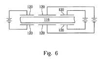
- FIG. 6is a schematic diagram of the electrode plates in an embodiment of the present invention.
- FIG. 7is a schematic diagram of the backlight unit with the luminous source and the diffuser having region with greater diffusion effect closer to the luminous means according to the present invention.
- the present inventionfocuses on a diffuser structure of a back light unit.
- the remaining structure of the back light unit of the present inventionis similar to the conventional back light unit 10 , and will not be explained again fully.
- FIG. 3 of a crosssectional diagram of a back light unit 110 according to the present invention.
- the back light unit 110is disposed under a display panel 118 for providing light source to the display panel 118 .
- the back light unit 110comprises a light source generator 112 for generating light beams and a diffuser 116 disposed on the light source generator 112 .
- the diffuser 116is composed of liquid crystal molecules and polymers.
- an additional reflective layer 114is often disposed under the light generator 112 .
- the reflective layer 114which may be composed of a metal layer, is used to reflect the light beams generated form the light source generator 112 upward so as to increase the output brightness.
- the light source generator 112is composed of one or a plurality of light tubes 113 .
- the light tubes 113may have specific shapes as shown in FIG. 3 or any other shapes.
- the light tubes 113usually occupy only parts of the region of the light generator 112 and leave a lot of unoccupied space. Therefore, the light output from the light generator 112 is not uniform, and varies according to locations. A region closer to the light tubes 113 has a higher luminous intensity.
- FIG. 5 of the diffuser 116 shown in FIG. 3As shown in FIG.
- the diffuser 116comprises a first region 116 A and a second region 116 B.
- An interval between the light tubes 113 and the first region 116 Ais smaller than that between the tubes 113 and the second region 116 B.
- the diffusing effect of the first region 116 Ais better than that of the second region 116 B. Therefore, the outputting light of the back light unit 110 is more uniform after passing through the diffuser 116 .
- the diffuser 116 of the present inventionmay comprise a plurality of regions with different scattering effects by using photo masks with different designed patterns or any other exposure methods.
- the first region 116 Ahas a shape corresponding to the shapes of the light tubes 113 .
- the area overlapping with the light tubes 113is defined as the first region 116 A.
- the diffuser 116is composed of liquid crystal molecules and polymers.
- the manufacturing method thereofincludes first filling the mixed monomer and liquid crystal molecules. Then, a curing process is performed by irradiation under UV light. When UV light with higher intensity is used, the liquid crystal molecules form smaller liquid crystal droplets, which have a higher refraction index.
- a first region 116 A and a second region 116 Bare defined by using photo masks during the curing process. Furthermore, the two regions 116 A and 116 B can be irradiated under the UV light with different intensities so that liquid droplets with different sizes are formed in the two regions.
- the first region 116 Awhich is composed of liquid crystal droplets with smaller sizes, has a higher refraction index than the second region 116 B. Because the refraction index distribution in the diffuser 116 corresponds to the shape of light tubes 113 , the uniformity of the light through the diffuser 116 can be improved.
- the sizes of liquid crystal droplets or the diffusing effect of the diffuser 116can be adjusted or set properly to an optimized condition according to the distribution of the brightness of the light tubes 113 so as to improve the uniformity of light output in advance.
- the size of the liquid crystal dropletsis about 0.1 to 1 ⁇ m.
- the diffuser 116is an electrically variable diffuser composed of polymer dispersed liquid crystals (PDLC). As shown in FIG. 6 , at least one pair of electrode plates 120 is used, with one electrode plate 120 being disposed on each side of the diffuser 116 .
- PDLCpolymer dispersed liquid crystals
- the electrode plates 120are electrically connected to a power supply so as to provide an external electric field to the diffuser 116 .
- the polymer dispersed liquid crystalis a kind of nematic liquid crystal and the refraction index of the liquid crystal molecules is variable according to the electric field applied thereon.
- the pattern of the electrode plates 120can be designed properly to fit the requirement of the back light unit 110 , for example the pattern of the electrode plates 120 may correspond to the shapes of the tubes 113 .
- the external electric fieldcan be adjusted so as to modify the diffusing effect of the diffuser 116 . Therefore, a new optimized
- the diffuser in the back light unit of the present inventioncan be adjusted properly according to the shapes or positionsof the tubes. Since the regions closer to the tubes have greater diffusion effect, the uniformity of the output light distribution can be improved.
- the present inventionalso provides an electrically variable diffuser which is composed of dispersed polymer liquid crystal molecules.
- the diffusing effect of the diffusercan be further adjusted by the electric field applied thereon according to the brightness of the tubes so as to solve the aforementioned problem of light tube brightness variation caused by aging.
Landscapes
- Physics & Mathematics (AREA)
- Nonlinear Science (AREA)
- Chemical & Material Sciences (AREA)
- Mathematical Physics (AREA)
- Crystallography & Structural Chemistry (AREA)
- General Physics & Mathematics (AREA)
- Optics & Photonics (AREA)
- Dispersion Chemistry (AREA)
- Liquid Crystal (AREA)
- Optical Elements Other Than Lenses (AREA)
Abstract
Description
Claims (10)
Applications Claiming Priority (2)
| Application Number | Priority Date | Filing Date | Title |
|---|---|---|---|
| TW091102276 | 2002-02-07 | ||
| TW091102276ATWI288848B (en) | 2002-02-07 | 2002-02-07 | Backlight unit and diffuser thereof |
Publications (2)
| Publication Number | Publication Date |
|---|---|
| US20030146680A1 US20030146680A1 (en) | 2003-08-07 |
| US6861789B2true US6861789B2 (en) | 2005-03-01 |
Family
ID=27657745
Family Applications (1)
| Application Number | Title | Priority Date | Filing Date |
|---|---|---|---|
| US10/065,289Expired - Fee RelatedUS6861789B2 (en) | 2002-02-07 | 2002-10-01 | Back light unit including a diffuser with various diffusion effects |
Country Status (2)
| Country | Link |
|---|---|
| US (1) | US6861789B2 (en) |
| TW (1) | TWI288848B (en) |
Cited By (33)
| Publication number | Priority date | Publication date | Assignee | Title |
|---|---|---|---|---|
| US20040150658A1 (en)* | 2002-12-03 | 2004-08-05 | Balarezo Brando H. | Display device |
| US20090207613A1 (en)* | 2008-02-20 | 2009-08-20 | Norimasa Furukawa | Light source system, light source device, and method of controlling light source |
| US20090262192A1 (en)* | 1995-05-22 | 2009-10-22 | Donnelly Corporation | Vehicular vision system |
| US7834954B2 (en) | 2007-04-13 | 2010-11-16 | Innocom Technology (Shenzhen) Co., Ltd. | Backlight module having a first diffuser with a haze ratio which gradually increases along two directions extending to a central region of the first diffuser and a second diffuser with a haze ratio gradually decreasing away from the light source and liquid crystal display having the same |
| US20110019260A1 (en)* | 2002-09-20 | 2011-01-27 | Donnelly Corporation | Vehicular electrochromic interior rearview mirror assembly |
| US20110045172A1 (en)* | 1994-05-05 | 2011-02-24 | Donnelly Corporation | Method of forming a mirrored bent cut glass shape for vehicular exterior rearview mirror assembly |
| US20110084198A1 (en)* | 2002-09-20 | 2011-04-14 | Donnelly Corporation | Interior rearview mirror information display system for a vehicle |
| US20110096387A1 (en)* | 2002-09-20 | 2011-04-28 | Donnelly Corporation | Reflective mirror assembly |
| US20110128137A1 (en)* | 1994-05-05 | 2011-06-02 | Donnelly Corporation | Vehicular blind spot indicator mirror |
| US20110166779A1 (en)* | 1999-11-24 | 2011-07-07 | Donnelly Corporation | Interior rearview mirror system |
| US8162493B2 (en) | 1999-11-24 | 2012-04-24 | Donnelly Corporation | Interior rearview mirror assembly for vehicle |
| US8170748B1 (en) | 2003-10-14 | 2012-05-01 | Donnelly Corporation | Vehicle information display system |
| US8179236B2 (en) | 2000-03-02 | 2012-05-15 | Donnelly Corporation | Video mirror system suitable for use in a vehicle |
| US8177376B2 (en) | 2002-06-06 | 2012-05-15 | Donnelly Corporation | Vehicular interior rearview mirror system |
| US8194133B2 (en) | 2000-03-02 | 2012-06-05 | Donnelly Corporation | Vehicular video mirror system |
| US8267559B2 (en) | 1997-08-25 | 2012-09-18 | Donnelly Corporation | Interior rearview mirror assembly for a vehicle |
| US8271187B2 (en) | 2000-03-02 | 2012-09-18 | Donnelly Corporation | Vehicular video mirror system |
| US8282253B2 (en) | 2004-11-22 | 2012-10-09 | Donnelly Corporation | Mirror reflective element sub-assembly for exterior rearview mirror of a vehicle |
| US8282226B2 (en) | 2002-06-06 | 2012-10-09 | Donnelly Corporation | Interior rearview mirror system |
| US8288711B2 (en) | 1998-01-07 | 2012-10-16 | Donnelly Corporation | Interior rearview mirror system with forwardly-viewing camera and a control |
| US8294975B2 (en) | 1997-08-25 | 2012-10-23 | Donnelly Corporation | Automotive rearview mirror assembly |
| US8304711B2 (en) | 2002-05-03 | 2012-11-06 | Donnelly Corporation | Vehicle rearview mirror system |
| US8309907B2 (en) | 1997-08-25 | 2012-11-13 | Donnelly Corporation | Accessory system suitable for use in a vehicle and accommodating a rain sensor |
| US8325028B2 (en) | 1998-01-07 | 2012-12-04 | Donnelly Corporation | Interior rearview mirror system |
| US8379289B2 (en) | 2003-10-02 | 2013-02-19 | Donnelly Corporation | Rearview mirror assembly for vehicle |
| US8427288B2 (en) | 2000-03-02 | 2013-04-23 | Donnelly Corporation | Rear vision system for a vehicle |
| US8503062B2 (en) | 2005-05-16 | 2013-08-06 | Donnelly Corporation | Rearview mirror element assembly for vehicle |
| US8508384B2 (en) | 2003-05-19 | 2013-08-13 | Donnelly Corporation | Rearview mirror assembly for vehicle |
| US8508383B2 (en) | 2008-03-31 | 2013-08-13 | Magna Mirrors of America, Inc | Interior rearview mirror system |
| US8525703B2 (en) | 1998-04-08 | 2013-09-03 | Donnelly Corporation | Interior rearview mirror system |
| US8653959B2 (en) | 2001-01-23 | 2014-02-18 | Donnelly Corporation | Video mirror system for a vehicle |
| US8779910B2 (en) | 1997-08-25 | 2014-07-15 | Donnelly Corporation | Interior rearview mirror system |
| US12093471B1 (en) | 2023-05-05 | 2024-09-17 | Chicony Power Technology Co., Ltd. | Touchpad and backlight module thereof |
Families Citing this family (6)
| Publication number | Priority date | Publication date | Assignee | Title |
|---|---|---|---|---|
| US7221363B2 (en)* | 2003-02-12 | 2007-05-22 | Gentex Corporation | Vehicle information displays |
| US7612942B2 (en)* | 2006-01-04 | 2009-11-03 | Guardian Industries Corp. | Optical diffuser having frit based coating with inorganic light diffusing pigments with variable particle size therein |
| US7446939B2 (en)* | 2005-12-22 | 2008-11-04 | Guardian Industries Corp. | Optical diffuser with UV blocking coating using inorganic materials for blocking UV |
| US7911699B2 (en)* | 2005-12-22 | 2011-03-22 | Guardian Industries Corp. | Optical diffuser with UV blocking coating |
| US7771103B2 (en)* | 2005-09-20 | 2010-08-10 | Guardian Industries Corp. | Optical diffuser with IR and/or UV blocking coating |
| US20070106263A1 (en)* | 2005-10-24 | 2007-05-10 | Ward Russell C | Intravenous identification luminaire (IV-ID) and light pipe, and light conductive intravenous delivery system |
Citations (7)
| Publication number | Priority date | Publication date | Assignee | Title |
|---|---|---|---|---|
| US4832458A (en) | 1984-08-28 | 1989-05-23 | Talig Corporation | Display for contrast enhancement |
| US5580932A (en) | 1991-09-27 | 1996-12-03 | Koike; Yasuhiro | Manufacturing method of a light scattering light guide |
| US5629785A (en) | 1995-05-04 | 1997-05-13 | Motorola, Inc. | Polymer dispersed liquid crystal display device with asymmetric optical diffuser |
| US5881201A (en) | 1997-03-11 | 1999-03-09 | Hoechst Celanese Corporation | Backlighting lightpipes for display applications |
| EP0918247A2 (en) | 1997-11-24 | 1999-05-26 | Ncr International Inc. | Visual displays |
| US6215535B1 (en) | 1992-08-11 | 2001-04-10 | Matsushita Electric Industrial Co., Ltd. | Light-modulation element and production method thereof |
| JP2002062528A (en) | 2000-08-21 | 2002-02-28 | Keiwa Inc | Backlight unit |
- 2002
- 2002-02-07TWTW091102276Apatent/TWI288848B/ennot_activeIP Right Cessation
- 2002-10-01USUS10/065,289patent/US6861789B2/ennot_activeExpired - Fee Related
Patent Citations (7)
| Publication number | Priority date | Publication date | Assignee | Title |
|---|---|---|---|---|
| US4832458A (en) | 1984-08-28 | 1989-05-23 | Talig Corporation | Display for contrast enhancement |
| US5580932A (en) | 1991-09-27 | 1996-12-03 | Koike; Yasuhiro | Manufacturing method of a light scattering light guide |
| US6215535B1 (en) | 1992-08-11 | 2001-04-10 | Matsushita Electric Industrial Co., Ltd. | Light-modulation element and production method thereof |
| US5629785A (en) | 1995-05-04 | 1997-05-13 | Motorola, Inc. | Polymer dispersed liquid crystal display device with asymmetric optical diffuser |
| US5881201A (en) | 1997-03-11 | 1999-03-09 | Hoechst Celanese Corporation | Backlighting lightpipes for display applications |
| EP0918247A2 (en) | 1997-11-24 | 1999-05-26 | Ncr International Inc. | Visual displays |
| JP2002062528A (en) | 2000-08-21 | 2002-02-28 | Keiwa Inc | Backlight unit |
Cited By (103)
| Publication number | Priority date | Publication date | Assignee | Title |
|---|---|---|---|---|
| US20110045172A1 (en)* | 1994-05-05 | 2011-02-24 | Donnelly Corporation | Method of forming a mirrored bent cut glass shape for vehicular exterior rearview mirror assembly |
| US8164817B2 (en) | 1994-05-05 | 2012-04-24 | Donnelly Corporation | Method of forming a mirrored bent cut glass shape for vehicular exterior rearview mirror assembly |
| US20110128137A1 (en)* | 1994-05-05 | 2011-06-02 | Donnelly Corporation | Vehicular blind spot indicator mirror |
| US8511841B2 (en) | 1994-05-05 | 2013-08-20 | Donnelly Corporation | Vehicular blind spot indicator mirror |
| US8559093B2 (en) | 1995-04-27 | 2013-10-15 | Donnelly Corporation | Electrochromic mirror reflective element for vehicular rearview mirror assembly |
| US8462204B2 (en) | 1995-05-22 | 2013-06-11 | Donnelly Corporation | Vehicular vision system |
| US20090262192A1 (en)* | 1995-05-22 | 2009-10-22 | Donnelly Corporation | Vehicular vision system |
| US8779910B2 (en) | 1997-08-25 | 2014-07-15 | Donnelly Corporation | Interior rearview mirror system |
| US8610992B2 (en) | 1997-08-25 | 2013-12-17 | Donnelly Corporation | Variable transmission window |
| US8267559B2 (en) | 1997-08-25 | 2012-09-18 | Donnelly Corporation | Interior rearview mirror assembly for a vehicle |
| US8309907B2 (en) | 1997-08-25 | 2012-11-13 | Donnelly Corporation | Accessory system suitable for use in a vehicle and accommodating a rain sensor |
| US8294975B2 (en) | 1997-08-25 | 2012-10-23 | Donnelly Corporation | Automotive rearview mirror assembly |
| US8325028B2 (en) | 1998-01-07 | 2012-12-04 | Donnelly Corporation | Interior rearview mirror system |
| US8288711B2 (en) | 1998-01-07 | 2012-10-16 | Donnelly Corporation | Interior rearview mirror system with forwardly-viewing camera and a control |
| US8525703B2 (en) | 1998-04-08 | 2013-09-03 | Donnelly Corporation | Interior rearview mirror system |
| US9221399B2 (en) | 1998-04-08 | 2015-12-29 | Magna Mirrors Of America, Inc. | Automotive communication system |
| US8884788B2 (en) | 1998-04-08 | 2014-11-11 | Donnelly Corporation | Automotive communication system |
| US9481306B2 (en) | 1998-04-08 | 2016-11-01 | Donnelly Corporation | Automotive communication system |
| US9019091B2 (en) | 1999-11-24 | 2015-04-28 | Donnelly Corporation | Interior rearview mirror system |
| US9376061B2 (en) | 1999-11-24 | 2016-06-28 | Donnelly Corporation | Accessory system of a vehicle |
| US10144355B2 (en) | 1999-11-24 | 2018-12-04 | Donnelly Corporation | Interior rearview mirror system for vehicle |
| US20110166779A1 (en)* | 1999-11-24 | 2011-07-07 | Donnelly Corporation | Interior rearview mirror system |
| US9278654B2 (en) | 1999-11-24 | 2016-03-08 | Donnelly Corporation | Interior rearview mirror system for vehicle |
| US8162493B2 (en) | 1999-11-24 | 2012-04-24 | Donnelly Corporation | Interior rearview mirror assembly for vehicle |
| US10179545B2 (en) | 2000-03-02 | 2019-01-15 | Magna Electronics Inc. | Park-aid system for vehicle |
| US8271187B2 (en) | 2000-03-02 | 2012-09-18 | Donnelly Corporation | Vehicular video mirror system |
| US8908039B2 (en) | 2000-03-02 | 2014-12-09 | Donnelly Corporation | Vehicular video mirror system |
| US8179236B2 (en) | 2000-03-02 | 2012-05-15 | Donnelly Corporation | Video mirror system suitable for use in a vehicle |
| US9809171B2 (en) | 2000-03-02 | 2017-11-07 | Magna Electronics Inc. | Vision system for vehicle |
| US8194133B2 (en) | 2000-03-02 | 2012-06-05 | Donnelly Corporation | Vehicular video mirror system |
| US8676491B2 (en) | 2000-03-02 | 2014-03-18 | Magna Electronics Inc. | Driver assist system for vehicle |
| US9315151B2 (en) | 2000-03-02 | 2016-04-19 | Magna Electronics Inc. | Driver assist system for vehicle |
| US8427288B2 (en) | 2000-03-02 | 2013-04-23 | Donnelly Corporation | Rear vision system for a vehicle |
| US9809168B2 (en) | 2000-03-02 | 2017-11-07 | Magna Electronics Inc. | Driver assist system for vehicle |
| US10239457B2 (en) | 2000-03-02 | 2019-03-26 | Magna Electronics Inc. | Vehicular vision system |
| US9014966B2 (en) | 2000-03-02 | 2015-04-21 | Magna Electronics Inc. | Driver assist system for vehicle |
| US8543330B2 (en) | 2000-03-02 | 2013-09-24 | Donnelly Corporation | Driver assist system for vehicle |
| US9783114B2 (en) | 2000-03-02 | 2017-10-10 | Donnelly Corporation | Vehicular video mirror system |
| US9019090B2 (en) | 2000-03-02 | 2015-04-28 | Magna Electronics Inc. | Vision system for vehicle |
| US10053013B2 (en) | 2000-03-02 | 2018-08-21 | Magna Electronics Inc. | Vision system for vehicle |
| US10131280B2 (en) | 2000-03-02 | 2018-11-20 | Donnelly Corporation | Vehicular video mirror system |
| US9694749B2 (en) | 2001-01-23 | 2017-07-04 | Magna Electronics Inc. | Trailer hitching aid system for vehicle |
| US8654433B2 (en) | 2001-01-23 | 2014-02-18 | Magna Mirrors Of America, Inc. | Rearview mirror assembly for vehicle |
| US8653959B2 (en) | 2001-01-23 | 2014-02-18 | Donnelly Corporation | Video mirror system for a vehicle |
| US9352623B2 (en) | 2001-01-23 | 2016-05-31 | Magna Electronics Inc. | Trailer hitching aid system for vehicle |
| US10272839B2 (en) | 2001-01-23 | 2019-04-30 | Magna Electronics Inc. | Rear seat occupant monitoring system for vehicle |
| US8304711B2 (en) | 2002-05-03 | 2012-11-06 | Donnelly Corporation | Vehicle rearview mirror system |
| US8282226B2 (en) | 2002-06-06 | 2012-10-09 | Donnelly Corporation | Interior rearview mirror system |
| US8465163B2 (en) | 2002-06-06 | 2013-06-18 | Donnelly Corporation | Interior rearview mirror system |
| US8465162B2 (en) | 2002-06-06 | 2013-06-18 | Donnelly Corporation | Vehicular interior rearview mirror system |
| US8608327B2 (en) | 2002-06-06 | 2013-12-17 | Donnelly Corporation | Automatic compass system for vehicle |
| US8177376B2 (en) | 2002-06-06 | 2012-05-15 | Donnelly Corporation | Vehicular interior rearview mirror system |
| US8727547B2 (en) | 2002-09-20 | 2014-05-20 | Donnelly Corporation | Variable reflectance mirror reflective element for exterior mirror assembly |
| US9878670B2 (en) | 2002-09-20 | 2018-01-30 | Donnelly Corporation | Variable reflectance mirror reflective element for exterior mirror assembly |
| US10661716B2 (en) | 2002-09-20 | 2020-05-26 | Donnelly Corporation | Vehicular exterior electrically variable reflectance mirror reflective element assembly |
| US8797627B2 (en) | 2002-09-20 | 2014-08-05 | Donnelly Corporation | Exterior rearview mirror assembly |
| US10538202B2 (en) | 2002-09-20 | 2020-01-21 | Donnelly Corporation | Method of manufacturing variable reflectance mirror reflective element for exterior mirror assembly |
| US10363875B2 (en) | 2002-09-20 | 2019-07-30 | Donnelly Corportion | Vehicular exterior electrically variable reflectance mirror reflective element assembly |
| US8228588B2 (en) | 2002-09-20 | 2012-07-24 | Donnelly Corporation | Interior rearview mirror information display system for a vehicle |
| US20110019260A1 (en)* | 2002-09-20 | 2011-01-27 | Donnelly Corporation | Vehicular electrochromic interior rearview mirror assembly |
| US20110084198A1 (en)* | 2002-09-20 | 2011-04-14 | Donnelly Corporation | Interior rearview mirror information display system for a vehicle |
| US9073491B2 (en) | 2002-09-20 | 2015-07-07 | Donnelly Corporation | Exterior rearview mirror assembly |
| US9090211B2 (en) | 2002-09-20 | 2015-07-28 | Donnelly Corporation | Variable reflectance mirror reflective element for exterior mirror assembly |
| US8506096B2 (en) | 2002-09-20 | 2013-08-13 | Donnelly Corporation | Variable reflectance mirror reflective element for exterior mirror assembly |
| US20110096387A1 (en)* | 2002-09-20 | 2011-04-28 | Donnelly Corporation | Reflective mirror assembly |
| US8400704B2 (en) | 2002-09-20 | 2013-03-19 | Donnelly Corporation | Interior rearview mirror system for a vehicle |
| US9341914B2 (en) | 2002-09-20 | 2016-05-17 | Donnelly Corporation | Variable reflectance mirror reflective element for exterior mirror assembly |
| US10029616B2 (en) | 2002-09-20 | 2018-07-24 | Donnelly Corporation | Rearview mirror assembly for vehicle |
| US8277059B2 (en) | 2002-09-20 | 2012-10-02 | Donnelly Corporation | Vehicular electrochromic interior rearview mirror assembly |
| US8335032B2 (en) | 2002-09-20 | 2012-12-18 | Donnelly Corporation | Reflective mirror assembly |
| US9545883B2 (en) | 2002-09-20 | 2017-01-17 | Donnelly Corporation | Exterior rearview mirror assembly |
| US7218306B2 (en)* | 2002-12-03 | 2007-05-15 | Valmark Industries, Inc. | Display device |
| US20040150658A1 (en)* | 2002-12-03 | 2004-08-05 | Balarezo Brando H. | Display device |
| US9783115B2 (en) | 2003-05-19 | 2017-10-10 | Donnelly Corporation | Rearview mirror assembly for vehicle |
| US8508384B2 (en) | 2003-05-19 | 2013-08-13 | Donnelly Corporation | Rearview mirror assembly for vehicle |
| US10449903B2 (en) | 2003-05-19 | 2019-10-22 | Donnelly Corporation | Rearview mirror assembly for vehicle |
| US11433816B2 (en) | 2003-05-19 | 2022-09-06 | Magna Mirrors Of America, Inc. | Vehicular interior rearview mirror assembly with cap portion |
| US9557584B2 (en) | 2003-05-19 | 2017-01-31 | Donnelly Corporation | Rearview mirror assembly for vehicle |
| US10166927B2 (en) | 2003-05-19 | 2019-01-01 | Donnelly Corporation | Rearview mirror assembly for vehicle |
| US10829052B2 (en) | 2003-05-19 | 2020-11-10 | Donnelly Corporation | Rearview mirror assembly for vehicle |
| US8379289B2 (en) | 2003-10-02 | 2013-02-19 | Donnelly Corporation | Rearview mirror assembly for vehicle |
| US8705161B2 (en) | 2003-10-02 | 2014-04-22 | Donnelly Corporation | Method of manufacturing a reflective element for a vehicular rearview mirror assembly |
| US8355839B2 (en) | 2003-10-14 | 2013-01-15 | Donnelly Corporation | Vehicle vision system with night vision function |
| US8577549B2 (en) | 2003-10-14 | 2013-11-05 | Donnelly Corporation | Information display system for a vehicle |
| US8170748B1 (en) | 2003-10-14 | 2012-05-01 | Donnelly Corporation | Vehicle information display system |
| US8282253B2 (en) | 2004-11-22 | 2012-10-09 | Donnelly Corporation | Mirror reflective element sub-assembly for exterior rearview mirror of a vehicle |
| US8503062B2 (en) | 2005-05-16 | 2013-08-06 | Donnelly Corporation | Rearview mirror element assembly for vehicle |
| US10829053B2 (en) | 2005-09-14 | 2020-11-10 | Magna Mirrors Of America, Inc. | Vehicular exterior rearview mirror assembly with blind spot indicator |
| US11072288B2 (en) | 2005-09-14 | 2021-07-27 | Magna Mirrors Of America, Inc. | Vehicular exterior rearview mirror assembly with blind spot indicator element |
| US9694753B2 (en) | 2005-09-14 | 2017-07-04 | Magna Mirrors Of America, Inc. | Mirror reflective element sub-assembly for exterior rearview mirror of a vehicle |
| US10308186B2 (en) | 2005-09-14 | 2019-06-04 | Magna Mirrors Of America, Inc. | Vehicular exterior rearview mirror assembly with blind spot indicator |
| US11285879B2 (en) | 2005-09-14 | 2022-03-29 | Magna Mirrors Of America, Inc. | Vehicular exterior rearview mirror assembly with blind spot indicator element |
| US9045091B2 (en) | 2005-09-14 | 2015-06-02 | Donnelly Corporation | Mirror reflective element sub-assembly for exterior rearview mirror of a vehicle |
| US10150417B2 (en) | 2005-09-14 | 2018-12-11 | Magna Mirrors Of America, Inc. | Mirror reflective element sub-assembly for exterior rearview mirror of a vehicle |
| US8833987B2 (en) | 2005-09-14 | 2014-09-16 | Donnelly Corporation | Mirror reflective element sub-assembly for exterior rearview mirror of a vehicle |
| US9758102B1 (en) | 2005-09-14 | 2017-09-12 | Magna Mirrors Of America, Inc. | Mirror reflective element sub-assembly for exterior rearview mirror of a vehicle |
| US11124121B2 (en) | 2005-11-01 | 2021-09-21 | Magna Electronics Inc. | Vehicular vision system |
| US11970113B2 (en) | 2005-11-01 | 2024-04-30 | Magna Electronics Inc. | Vehicular vision system |
| US7834954B2 (en) | 2007-04-13 | 2010-11-16 | Innocom Technology (Shenzhen) Co., Ltd. | Backlight module having a first diffuser with a haze ratio which gradually increases along two directions extending to a central region of the first diffuser and a second diffuser with a haze ratio gradually decreasing away from the light source and liquid crystal display having the same |
| US20090207613A1 (en)* | 2008-02-20 | 2009-08-20 | Norimasa Furukawa | Light source system, light source device, and method of controlling light source |
| US10175477B2 (en) | 2008-03-31 | 2019-01-08 | Magna Mirrors Of America, Inc. | Display system for vehicle |
| US8508383B2 (en) | 2008-03-31 | 2013-08-13 | Magna Mirrors of America, Inc | Interior rearview mirror system |
| US12093471B1 (en) | 2023-05-05 | 2024-09-17 | Chicony Power Technology Co., Ltd. | Touchpad and backlight module thereof |
Also Published As
| Publication number | Publication date |
|---|---|
| TWI288848B (en) | 2007-10-21 |
| US20030146680A1 (en) | 2003-08-07 |
Similar Documents
| Publication | Publication Date | Title |
|---|---|---|
| US6861789B2 (en) | Back light unit including a diffuser with various diffusion effects | |
| US10228589B2 (en) | Backlight unit and liquid crystal display device including the same | |
| JP5129906B2 (en) | LIQUID CRYSTAL DISPLAY DEVICE LIGHTING METHOD, LIQUID CRYSTAL DISPLAY DEVICE BACKLIGHT ASSEMBLY FOR IMPLEMENTING THE METHOD, AND LIQUID CRYSTAL DISPLAY DEVICE USING THE SAME | |
| US8045092B2 (en) | Multifunctional optical sheet and liquid crystal display device including the same | |
| US20100165239A1 (en) | Liquid crystal display device having good heat radiating function | |
| US8581942B2 (en) | Backlight unit for liquid crystal display device and driving method of the same | |
| US7995160B2 (en) | Prism sheet and liquid crystal display having the same | |
| KR20160022224A (en) | Light guide plate and backlight unit having the same | |
| CN103717961A (en) | Illumination device and display device | |
| US9864231B2 (en) | Backlight unit and liquid crystal display device including the same | |
| KR102222297B1 (en) | Reflector for uniform brightness and liquid crystal display device having thereof | |
| CN100421008C (en) | Backlight unit and liquid crystal display using same | |
| US10914982B2 (en) | Backlight module and display device | |
| JP2005196178A (en) | Backlight structure of liquid crystal display element | |
| KR101948169B1 (en) | Backlight unit and liquid crystal display device using the same | |
| GB2544895A (en) | Backlight unit and liquid crystal display device including the same | |
| CN103728681B (en) | Prismatic lens, the back light unit including the prismatic lens and its manufacturing method | |
| US7973879B2 (en) | Backlight unit and liquid crystal display device having first and second diffusion layers that have different haze values | |
| KR101114854B1 (en) | A backlight unit | |
| KR102030412B1 (en) | Light guide plate having rounded polyggon pattern and liquid cyrstal display device having thereof | |
| KR100880217B1 (en) | Backlight | |
| JP2004198725A (en) | Liquid crystal display, direct back light, and diffusing plate | |
| KR20150001420A (en) | Glass diffusion plate, backlight unit using the glass diffusion plate, and liquid crystal display using the backlight unit | |
| KR102053442B1 (en) | Optical sheet and liquid crystal display device comprising the same | |
| KR20120063940A (en) | Backlight unit and lcd module including the same |
Legal Events
| Date | Code | Title | Description |
|---|---|---|---|
| AS | Assignment | Owner name:CHI MEI OPTOELECTRONICS CORPORATION, TAIWAN Free format text:ASSIGNMENT OF ASSIGNORS INTEREST;ASSIGNOR:WEI, CHUNG-KUANG;REEL/FRAME:013135/0551 Effective date:20020101 | |
| FPAY | Fee payment | Year of fee payment:4 | |
| AS | Assignment | Owner name:CHIMEI INNOLUX CORPORATION,TAIWAN Free format text:MERGER;ASSIGNOR:CHI MEI OPTOELECTRONICS CORP.;REEL/FRAME:024329/0752 Effective date:20100318 Owner name:CHIMEI INNOLUX CORPORATION, TAIWAN Free format text:MERGER;ASSIGNOR:CHI MEI OPTOELECTRONICS CORP.;REEL/FRAME:024329/0752 Effective date:20100318 | |
| FPAY | Fee payment | Year of fee payment:8 | |
| AS | Assignment | Owner name:INNOLUX CORPORATION, TAIWAN Free format text:CHANGE OF NAME;ASSIGNOR:CHIMEI INNOLUX CORPORATION;REEL/FRAME:032604/0487 Effective date:20121219 | |
| REMI | Maintenance fee reminder mailed | ||
| LAPS | Lapse for failure to pay maintenance fees | ||
| STCH | Information on status: patent discontinuation | Free format text:PATENT EXPIRED DUE TO NONPAYMENT OF MAINTENANCE FEES UNDER 37 CFR 1.362 | |
| FP | Lapsed due to failure to pay maintenance fee | Effective date:20170301 |