US6860878B2 - Interchangeable instrument - Google Patents
Interchangeable instrumentDownload PDFInfo
- Publication number
- US6860878B2 US6860878B2US10/097,923US9792302AUS6860878B2US 6860878 B2US6860878 B2US 6860878B2US 9792302 AUS9792302 AUS 9792302AUS 6860878 B2US6860878 B2US 6860878B2
- Authority
- US
- United States
- Prior art keywords
- instrument
- driver
- set forth
- medical apparatus
- remotely controllable
- Prior art date
- Legal status (The legal status is an assumption and is not a legal conclusion. Google has not performed a legal analysis and makes no representation as to the accuracy of the status listed.)
- Expired - Lifetime
Links
Images


Classifications
- A—HUMAN NECESSITIES
- A61—MEDICAL OR VETERINARY SCIENCE; HYGIENE
- A61B—DIAGNOSIS; SURGERY; IDENTIFICATION
- A61B17/00—Surgical instruments, devices or methods
- A61B17/00234—Surgical instruments, devices or methods for minimally invasive surgery
- A—HUMAN NECESSITIES
- A61—MEDICAL OR VETERINARY SCIENCE; HYGIENE
- A61B—DIAGNOSIS; SURGERY; IDENTIFICATION
- A61B34/00—Computer-aided surgery; Manipulators or robots specially adapted for use in surgery
- A61B34/30—Surgical robots
- A—HUMAN NECESSITIES
- A61—MEDICAL OR VETERINARY SCIENCE; HYGIENE
- A61B—DIAGNOSIS; SURGERY; IDENTIFICATION
- A61B34/00—Computer-aided surgery; Manipulators or robots specially adapted for use in surgery
- A61B34/30—Surgical robots
- A61B34/35—Surgical robots for telesurgery
- A—HUMAN NECESSITIES
- A61—MEDICAL OR VETERINARY SCIENCE; HYGIENE
- A61B—DIAGNOSIS; SURGERY; IDENTIFICATION
- A61B34/00—Computer-aided surgery; Manipulators or robots specially adapted for use in surgery
- A61B34/30—Surgical robots
- A61B34/37—Leader-follower robots
- A—HUMAN NECESSITIES
- A61—MEDICAL OR VETERINARY SCIENCE; HYGIENE
- A61B—DIAGNOSIS; SURGERY; IDENTIFICATION
- A61B34/00—Computer-aided surgery; Manipulators or robots specially adapted for use in surgery
- A61B34/70—Manipulators specially adapted for use in surgery
- A—HUMAN NECESSITIES
- A61—MEDICAL OR VETERINARY SCIENCE; HYGIENE
- A61B—DIAGNOSIS; SURGERY; IDENTIFICATION
- A61B34/00—Computer-aided surgery; Manipulators or robots specially adapted for use in surgery
- A61B34/70—Manipulators specially adapted for use in surgery
- A61B34/71—Manipulators operated by drive cable mechanisms
- A—HUMAN NECESSITIES
- A61—MEDICAL OR VETERINARY SCIENCE; HYGIENE
- A61B—DIAGNOSIS; SURGERY; IDENTIFICATION
- A61B34/00—Computer-aided surgery; Manipulators or robots specially adapted for use in surgery
- A61B34/70—Manipulators specially adapted for use in surgery
- A61B34/72—Micromanipulators
- A—HUMAN NECESSITIES
- A61—MEDICAL OR VETERINARY SCIENCE; HYGIENE
- A61B—DIAGNOSIS; SURGERY; IDENTIFICATION
- A61B34/00—Computer-aided surgery; Manipulators or robots specially adapted for use in surgery
- A61B34/70—Manipulators specially adapted for use in surgery
- A61B34/76—Manipulators having means for providing feel, e.g. force or tactile feedback
- A—HUMAN NECESSITIES
- A61—MEDICAL OR VETERINARY SCIENCE; HYGIENE
- A61B—DIAGNOSIS; SURGERY; IDENTIFICATION
- A61B5/00—Measuring for diagnostic purposes; Identification of persons
- A61B5/0059—Measuring for diagnostic purposes; Identification of persons using light, e.g. diagnosis by transillumination, diascopy, fluorescence
- A61B5/0082—Measuring for diagnostic purposes; Identification of persons using light, e.g. diagnosis by transillumination, diascopy, fluorescence adapted for particular medical purposes
- A61B5/0084—Measuring for diagnostic purposes; Identification of persons using light, e.g. diagnosis by transillumination, diascopy, fluorescence adapted for particular medical purposes for introduction into the body, e.g. by catheters
- A61B5/0086—Measuring for diagnostic purposes; Identification of persons using light, e.g. diagnosis by transillumination, diascopy, fluorescence adapted for particular medical purposes for introduction into the body, e.g. by catheters using infrared radiation
- A—HUMAN NECESSITIES
- A61—MEDICAL OR VETERINARY SCIENCE; HYGIENE
- A61B—DIAGNOSIS; SURGERY; IDENTIFICATION
- A61B5/00—Measuring for diagnostic purposes; Identification of persons
- A61B5/24—Detecting, measuring or recording bioelectric or biomagnetic signals of the body or parts thereof
- A—HUMAN NECESSITIES
- A61—MEDICAL OR VETERINARY SCIENCE; HYGIENE
- A61B—DIAGNOSIS; SURGERY; IDENTIFICATION
- A61B5/00—Measuring for diagnostic purposes; Identification of persons
- A61B5/41—Detecting, measuring or recording for evaluating the immune or lymphatic systems
- A61B5/414—Evaluating particular organs or parts of the immune or lymphatic systems
- A61B5/415—Evaluating particular organs or parts of the immune or lymphatic systems the glands, e.g. tonsils, adenoids or thymus
- A—HUMAN NECESSITIES
- A61—MEDICAL OR VETERINARY SCIENCE; HYGIENE
- A61B—DIAGNOSIS; SURGERY; IDENTIFICATION
- A61B5/00—Measuring for diagnostic purposes; Identification of persons
- A61B5/41—Detecting, measuring or recording for evaluating the immune or lymphatic systems
- A61B5/414—Evaluating particular organs or parts of the immune or lymphatic systems
- A61B5/416—Evaluating particular organs or parts of the immune or lymphatic systems the spleen
- A—HUMAN NECESSITIES
- A61—MEDICAL OR VETERINARY SCIENCE; HYGIENE
- A61B—DIAGNOSIS; SURGERY; IDENTIFICATION
- A61B5/00—Measuring for diagnostic purposes; Identification of persons
- A61B5/41—Detecting, measuring or recording for evaluating the immune or lymphatic systems
- A61B5/414—Evaluating particular organs or parts of the immune or lymphatic systems
- A61B5/418—Evaluating particular organs or parts of the immune or lymphatic systems lymph vessels, ducts or nodes
- A—HUMAN NECESSITIES
- A61—MEDICAL OR VETERINARY SCIENCE; HYGIENE
- A61B—DIAGNOSIS; SURGERY; IDENTIFICATION
- A61B5/00—Measuring for diagnostic purposes; Identification of persons
- A61B5/48—Other medical applications
- A61B5/4887—Locating particular structures in or on the body
- A61B5/4893—Nerves
- A—HUMAN NECESSITIES
- A61—MEDICAL OR VETERINARY SCIENCE; HYGIENE
- A61B—DIAGNOSIS; SURGERY; IDENTIFICATION
- A61B6/00—Apparatus or devices for radiation diagnosis; Apparatus or devices for radiation diagnosis combined with radiation therapy equipment
- A61B6/42—Arrangements for detecting radiation specially adapted for radiation diagnosis
- A61B6/4208—Arrangements for detecting radiation specially adapted for radiation diagnosis characterised by using a particular type of detector
- A61B6/425—Arrangements for detecting radiation specially adapted for radiation diagnosis characterised by using a particular type of detector using detectors specially adapted to be used in the interior of the body
- A—HUMAN NECESSITIES
- A61—MEDICAL OR VETERINARY SCIENCE; HYGIENE
- A61B—DIAGNOSIS; SURGERY; IDENTIFICATION
- A61B90/00—Instruments, implements or accessories specially adapted for surgery or diagnosis and not covered by any of the groups A61B1/00 - A61B50/00, e.g. for luxation treatment or for protecting wound edges
- A61B90/36—Image-producing devices or illumination devices not otherwise provided for
- A—HUMAN NECESSITIES
- A61—MEDICAL OR VETERINARY SCIENCE; HYGIENE
- A61B—DIAGNOSIS; SURGERY; IDENTIFICATION
- A61B17/00—Surgical instruments, devices or methods
- A61B17/00491—Surgical glue applicators
- A—HUMAN NECESSITIES
- A61—MEDICAL OR VETERINARY SCIENCE; HYGIENE
- A61B—DIAGNOSIS; SURGERY; IDENTIFICATION
- A61B17/00—Surgical instruments, devices or methods
- A61B17/28—Surgical forceps
- A61B17/29—Forceps for use in minimally invasive surgery
- A—HUMAN NECESSITIES
- A61—MEDICAL OR VETERINARY SCIENCE; HYGIENE
- A61B—DIAGNOSIS; SURGERY; IDENTIFICATION
- A61B17/00—Surgical instruments, devices or methods
- A61B2017/00017—Electrical control of surgical instruments
- A61B2017/00022—Sensing or detecting at the treatment site
- A—HUMAN NECESSITIES
- A61—MEDICAL OR VETERINARY SCIENCE; HYGIENE
- A61B—DIAGNOSIS; SURGERY; IDENTIFICATION
- A61B17/00—Surgical instruments, devices or methods
- A61B2017/00017—Electrical control of surgical instruments
- A61B2017/00022—Sensing or detecting at the treatment site
- A61B2017/00026—Conductivity or impedance, e.g. of tissue
- A—HUMAN NECESSITIES
- A61—MEDICAL OR VETERINARY SCIENCE; HYGIENE
- A61B—DIAGNOSIS; SURGERY; IDENTIFICATION
- A61B17/00—Surgical instruments, devices or methods
- A61B2017/00017—Electrical control of surgical instruments
- A61B2017/00022—Sensing or detecting at the treatment site
- A61B2017/00039—Electric or electromagnetic phenomena other than conductivity, e.g. capacity, inductivity, Hall effect
- A—HUMAN NECESSITIES
- A61—MEDICAL OR VETERINARY SCIENCE; HYGIENE
- A61B—DIAGNOSIS; SURGERY; IDENTIFICATION
- A61B17/00—Surgical instruments, devices or methods
- A61B2017/00017—Electrical control of surgical instruments
- A61B2017/00022—Sensing or detecting at the treatment site
- A61B2017/00084—Temperature
- A61B2017/00088—Temperature using thermistors
- A—HUMAN NECESSITIES
- A61—MEDICAL OR VETERINARY SCIENCE; HYGIENE
- A61B—DIAGNOSIS; SURGERY; IDENTIFICATION
- A61B17/00—Surgical instruments, devices or methods
- A61B2017/00017—Electrical control of surgical instruments
- A61B2017/00115—Electrical control of surgical instruments with audible or visual output
- A—HUMAN NECESSITIES
- A61—MEDICAL OR VETERINARY SCIENCE; HYGIENE
- A61B—DIAGNOSIS; SURGERY; IDENTIFICATION
- A61B17/00—Surgical instruments, devices or methods
- A61B17/00234—Surgical instruments, devices or methods for minimally invasive surgery
- A61B2017/00362—Packages or dispensers for MIS instruments
- A—HUMAN NECESSITIES
- A61—MEDICAL OR VETERINARY SCIENCE; HYGIENE
- A61B—DIAGNOSIS; SURGERY; IDENTIFICATION
- A61B17/00—Surgical instruments, devices or methods
- A61B2017/0046—Surgical instruments, devices or methods with a releasable handle; with handle and operating part separable
- A61B2017/00473—Distal part, e.g. tip or head
- A—HUMAN NECESSITIES
- A61—MEDICAL OR VETERINARY SCIENCE; HYGIENE
- A61B—DIAGNOSIS; SURGERY; IDENTIFICATION
- A61B17/00—Surgical instruments, devices or methods
- A61B2017/00477—Coupling
- A—HUMAN NECESSITIES
- A61—MEDICAL OR VETERINARY SCIENCE; HYGIENE
- A61B—DIAGNOSIS; SURGERY; IDENTIFICATION
- A61B17/00—Surgical instruments, devices or methods
- A61B2017/00477—Coupling
- A61B2017/00482—Coupling with a code
- A—HUMAN NECESSITIES
- A61—MEDICAL OR VETERINARY SCIENCE; HYGIENE
- A61B—DIAGNOSIS; SURGERY; IDENTIFICATION
- A61B34/00—Computer-aided surgery; Manipulators or robots specially adapted for use in surgery
- A61B34/10—Computer-aided planning, simulation or modelling of surgical operations
- A61B2034/101—Computer-aided simulation of surgical operations
- A61B2034/105—Modelling of the patient, e.g. for ligaments or bones
- A—HUMAN NECESSITIES
- A61—MEDICAL OR VETERINARY SCIENCE; HYGIENE
- A61B—DIAGNOSIS; SURGERY; IDENTIFICATION
- A61B34/00—Computer-aided surgery; Manipulators or robots specially adapted for use in surgery
- A61B34/30—Surgical robots
- A61B2034/301—Surgical robots for introducing or steering flexible instruments inserted into the body, e.g. catheters or endoscopes
- A—HUMAN NECESSITIES
- A61—MEDICAL OR VETERINARY SCIENCE; HYGIENE
- A61B—DIAGNOSIS; SURGERY; IDENTIFICATION
- A61B90/00—Instruments, implements or accessories specially adapted for surgery or diagnosis and not covered by any of the groups A61B1/00 - A61B50/00, e.g. for luxation treatment or for protecting wound edges
- A61B90/06—Measuring instruments not otherwise provided for
- A61B2090/064—Measuring instruments not otherwise provided for for measuring force, pressure or mechanical tension
- A—HUMAN NECESSITIES
- A61—MEDICAL OR VETERINARY SCIENCE; HYGIENE
- A61B—DIAGNOSIS; SURGERY; IDENTIFICATION
- A61B90/00—Instruments, implements or accessories specially adapted for surgery or diagnosis and not covered by any of the groups A61B1/00 - A61B50/00, e.g. for luxation treatment or for protecting wound edges
- A61B90/36—Image-producing devices or illumination devices not otherwise provided for
- A61B2090/364—Correlation of different images or relation of image positions in respect to the body
- A61B2090/365—Correlation of different images or relation of image positions in respect to the body augmented reality, i.e. correlating a live optical image with another image
- A—HUMAN NECESSITIES
- A61—MEDICAL OR VETERINARY SCIENCE; HYGIENE
- A61B—DIAGNOSIS; SURGERY; IDENTIFICATION
- A61B34/00—Computer-aided surgery; Manipulators or robots specially adapted for use in surgery
- A61B34/10—Computer-aided planning, simulation or modelling of surgical operations
- A—HUMAN NECESSITIES
- A61—MEDICAL OR VETERINARY SCIENCE; HYGIENE
- A61B—DIAGNOSIS; SURGERY; IDENTIFICATION
- A61B34/00—Computer-aided surgery; Manipulators or robots specially adapted for use in surgery
- A61B34/20—Surgical navigation systems; Devices for tracking or guiding surgical instruments, e.g. for frameless stereotaxis
- A—HUMAN NECESSITIES
- A61—MEDICAL OR VETERINARY SCIENCE; HYGIENE
- A61B—DIAGNOSIS; SURGERY; IDENTIFICATION
- A61B5/00—Measuring for diagnostic purposes; Identification of persons
- A61B5/0059—Measuring for diagnostic purposes; Identification of persons using light, e.g. diagnosis by transillumination, diascopy, fluorescence
- A61B5/0082—Measuring for diagnostic purposes; Identification of persons using light, e.g. diagnosis by transillumination, diascopy, fluorescence adapted for particular medical purposes
- A61B5/0084—Measuring for diagnostic purposes; Identification of persons using light, e.g. diagnosis by transillumination, diascopy, fluorescence adapted for particular medical purposes for introduction into the body, e.g. by catheters
- A—HUMAN NECESSITIES
- A61—MEDICAL OR VETERINARY SCIENCE; HYGIENE
- A61B—DIAGNOSIS; SURGERY; IDENTIFICATION
- A61B5/00—Measuring for diagnostic purposes; Identification of persons
- A61B5/01—Measuring temperature of body parts ; Diagnostic temperature sensing, e.g. for malignant or inflamed tissue
- A61B5/015—By temperature mapping of body part
- A—HUMAN NECESSITIES
- A61—MEDICAL OR VETERINARY SCIENCE; HYGIENE
- A61B—DIAGNOSIS; SURGERY; IDENTIFICATION
- A61B50/00—Containers, covers, furniture or holders specially adapted for surgical or diagnostic appliances or instruments, e.g. sterile covers
- A61B50/30—Containers specially adapted for packaging, protecting, dispensing, collecting or disposing of surgical or diagnostic appliances or instruments
- A—HUMAN NECESSITIES
- A61—MEDICAL OR VETERINARY SCIENCE; HYGIENE
- A61B—DIAGNOSIS; SURGERY; IDENTIFICATION
- A61B90/00—Instruments, implements or accessories specially adapted for surgery or diagnosis and not covered by any of the groups A61B1/00 - A61B50/00, e.g. for luxation treatment or for protecting wound edges
- A61B90/36—Image-producing devices or illumination devices not otherwise provided for
- A61B90/361—Image-producing devices, e.g. surgical cameras
Definitions
- the present inventionrelates in general to medical instrumentation. More particularly, the present invention relates to a surgical instrumentation system that enables the interchange of any one of a number of different surgical instruments at an operative site, including fluid dispensing instruments.
- a surgeonuses a variety of different surgical implements with the total number that are used being a function of the particular operation being performed. For the most part these instruments or implements are hand held devices directly held and manipulated by the surgeon through the open incision. Typical surgical instruments include forceps, needle drivers, scissors, scalpels, etc. A number of different instruments or implements may be used during an operation depending upon the complexity of the medical procedure being performed, and even a greater number of instrument exchanges occur. Thus, a great deal of time may be spent during the surgery simply in exchanging between different types of instruments.
- MISminimally invasive surgery
- incision or incisionsare relatively small, typically 5 mm to 10 mm in diameter, in comparison to open surgery.
- MIS instrumentationsuch instruments as forceps, scissors, etc., are inserted into the body at the end of long slender push rods actuated by the surgeon from outside the patient. Due to the size and increased complexity of these instruments it may be even more difficult to carry out an exchange due to the need to extract and re-insert through a relatively small incision.
- Both open and MIS proceduresinvolve control of the instrument directly by the human hand.
- the surgeondirectly holds and manipulates the instrument, while in MIS the operable tool (scalpel, scissors, etc.) is controlled by hand, but through some type of mechanical transmission that intercouples from outside the patient to an internal operative site.
- robotic surgical systemsIn more recent years computer control of instrumentation systems has come into being, typically referred to as robotic surgical systems, in which a surgeon controls an instrument carrying an end effector from a remote site, and through an electronic controller or the like. These robotic systems do provide an improvement in the dexterity with which medical procedures can be performed. However, even in these more advanced systems there is still a need to manually exchange instruments during a procedure.
- the present inventionis directed to a system, apparatus, or method for enabling the exchange or interchange between one of several different instruments or implements, so that these different instruments or implements can be readily delivered to an operative or target site within a patient for performing a medical or surgical procedure.
- the present inventioncarries out this exchange or interchange without the usual manual withdrawal and insertion that is typical of prior art systems, and can be said to perform this interchange or exchange essentially automatically, with little or no manual intervention.
- the principles of the present inventionare intended to apply to any instruments or implements, whether for open, MIS, or robotic surgery uses.
- the instruments or implementsmay carry tools or end effectors that may be of any type including, but not limited to, articulated and non-articulated types, and/or may carry fluid retaining and dispensing instruments or fluid coupling or transfer instruments.
- an interchangeable instrument apparatusthat includes a plurality of separate instrument members each capable of assisting in a different phase of a medical procedure to be performed at an operative site within the anatomy.
- An instrument storage chamberreleasably receives the plurality of instrument members.
- the instrument membersare accommodated in separate storage locations within the instrument storage chamber.
- An instrument driveris constructed and arranged for cooperative positioning relative to the instrument storage chamber, for selective alignment with one of the instrument members at a time, and for displacing or driving the aligned instrument member from the instrument storage chamber toward the operative site.
- At least one of the instrument driver and instrument storage chamberare positionally controllable so as to provide relative displacement therebetween so as to selectively align the instrument driver with another of the instrument members.
- the plurality of separate instrument membersmay include either a mechanically actuable member or a fluid dispensing member.
- a surgical instrument apparatusthat comprises an instrument member that includes two sections including a work section that supports at its distal end a selectively actuable member used in performing a medical procedure at an operative site within the anatomy, and a driver section that is releasably engageable with the work section.
- the apparatusalso includes a guide member for receiving the work section and the driver section, and for directing, upon engagement of said driver section with said work section, the delivery of the selectively actuable member to the operative site.
- the driver sectionin an inoperative position thereof, is disengaged from the work section, and in an operative position thereof, is engageable with the work section to direct the work section, via the guide member, to the operative site, and further is engageable with the work section to enable operative coupling to the selectively actuable member for actuation thereof from a remote drive unit.
- a method of delivering, to an internal operative site, a selected one of a plurality of instrumentscomprising the steps of; storing a plurality of separate instruments in a storage chamber with each instrument capable of assisting in a different phase of a medical procedure to be performed at the operative site, and providing an instrument driver constructed and arranged for;
- a storage chamberthat supports a plurality of separately arranged instruments, and further includes inlet and outlet ports.
- the outlet portis arranged in alignment with the target or operative site where the instrument is to be delivered.
- the instrumentcarries at its distal end a work implement that may be either a tool or a fluid releasing device such as a syringe member.
- An instrument driveris in alignment with the inlet port, and is adapted to engage a registered instrument disposed in the storage chamber, so as to deliver the selected instrument, via the outlet port, to the target or operative site.
- the instrument driverin addition to engagement with the instrument, also operatively couples with and enables operation of the work implement of the instrument.
- the storage chamberis selectively operable, upon command, to permit different instruments to align between the inlet and outlet ports.
- a surgical instrument apparatusthat includes an instrument member having a work section that supports at its distal end either a tool or fluid member used in performing a medical procedure at an operative site within the anatomy, and a driver section that is releasably engageable with the work section.
- a guide memberreceives the work section and the drive section, and is for directing, upon engagement of the driver section with the work section, delivery to the operative site.
- the driver sectionin an inoperative position thereof, is disengaged from the work section, and in an operative position thereof, is engageable with the work section to direct the work section, via the guide member, to the operative site, and is further engageable with the work section to enable operative coupling to the tool or fluid member for actuation thereof from a remote drive unit.
- the apparatusalso preferably includes an interface or coupling section between the work and driver sections for selectively and releasably intercoupling therebetween.
- the present inventionis also directed to an interchangeable medical instrument system that includes an instrument storage retainer that supports a plurality of separately arranged instruments, and further includes inlet and outlet ports, the outlet port arranged in alignment with the a target or operative site where the instrument is to be delivered for performing a medical procedure.
- a work implementis supported at the distal end of each instrument.
- An instrument transporteris in alignment with the inlet port, and adapted to engage a registered instrument disposed in the storage retainer, so as to deliver the selected instrument, via the outlet port to the target or operative site.
- the instrument transporterin addition to engagement with the instrument, also operatively couples with and enables operation of the work implement of the instrument
- the retaineris selectively operable, upon command, to permit different instruments to align between the inlet and outlet ports.
- the instrumentsmay include either an articulating instrument or a fluid ejecting instrument.
- the present inventionis also directed to an interchangeable instrument system that includes an instrument retainer having multiple storage location for receiving a plurality of instruments disposed separately in the respective storage locations, and an instrument driver constructed and arranged for cooperative positioning relative to the instrument retainer, for selective alignment with one of the instruments at a time, and for displacing the aligned instrument from the instrument retainer and toward the operative site.
- An indexing mechanismcontrols the position of the instrument retainer so as to selectively align different instruments with the instrument driver.
- An actuation memberis disposed at a user interface for controlling the indexing mechanism.
- an interchangeable instrument systemthat includes a plurality of medical instruments, an instrument retainer for releasably holding the plurality of instruments, and an instrument transporter associated with the instrument retainer, for selective alignment with one of the instruments at a time, and for displacing the aligned instrument from the instrument retainer toward an operative site in a subject.
- Either the instrument retainer or instrument transportermay be positionally controllable so as to provide relative displacement therebetween so as to selectively align the instrument transporter with another instrument.
- the instrument retainermay comprise a rotating chamber having a plurality of passages therein.
- the instrument retainermay comprise a linear chamber for receiving the instruments.
- the transportermay be positioned in parallel to the linear chamber, and a selected instrument is moved transversely out of the chamber for alignment with the instrument transporter.
- a remotely controllable medical apparatuscomprising: a remote user interface manually manipulable by a user for sending operation command signals to a signal processor, the signal processor processing the command signals and sending processed signals to a drive mechanism; an instrument exchange mechanism mechanically intercoupled to the drive mechanism; the instrument exchange mechanism comprising a shaft and an instrument delivery mechanism containing two or more selected instruments; the shaft having a lumen which readily receives the selected instruments for insertion and withdrawal from the instrument delivery mechanism; an instrument drive mechanism mechanically intercoupled to the drive mechanism and readily mechanically couplable to and decouplable from an instrument; the instrument drive mechanism being remotely drivable via the user interface to operably couple to and drive an instrument; the instrument being of one of the type of, an articulating instrument and a fluid dispensing instrument.
- a remotely controllable medical apparatuscomprising: a remote user interface manually manipulable by a user for sending operation command signals to a signal processor, the signal processor processing the command signals and sending processed signals to a drive mechanism; an instrument exchange mechanism mechanically intercoupled to the drive mechanism; the instrument exchange mechanism comprising an instrument delivery mechanism containing two or more selectable instruments; the instrument delivery mechanism is drivably movable to align a selected instrument with an operative site for insertion and withdrawal to and from the operative site; the instrument delivery mechanism being remotely drivable via the user interface to insert and withdraw selected instruments.
- the instrumentmay be either a mechanically actuable instrument or a fluid dispensing instrument.
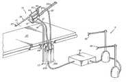
- FIG. 1is a perspective view of one embodiment of a robotic surgical system in which the interchangeable instrument principles of the present invention are applied;
- FIG. 2is a perspective view showing a portion of the system of FIG. 1 , particularly the storage chamber and the driving mechanism;
- FIG. 3is a cross-sectional view illustrating the storage chamber, the driver and the associated positioning of components, and as taken along line 3 — 3 of FIG. 2 ;
- FIG. 4is a perspective view showing some further detail of the instrument in this first embodiment
- FIG. 5is a partial cross-sectional view showing further details of the driver and instrument in this first embodiment
- FIG. 6is a further cross-sectional view similar to that illustrated in FIG. 5 but showing the driver and instrument in an interlocked position;
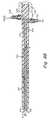
- FIG. 7is a schematic cross-sectional perspective view that illustrates details of one embodiment of the instrument of the present invention.
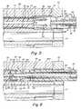
- FIG. 8is a cross-sectional view similar to that shown in FIG. 3 , but for an alternate embodiment of the invention that couples with an external fluid source;
- FIG. 8Ais an exploded perspective view illustrating further details of the coupling or interlocking sections of the arrangement shown in FIG. 8 ;
- FIG. 8Bis a schematic cross-sectional view of still another alternate embodiment that includes an closed loop system with drainage
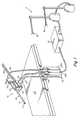
- FIG. 9is a perspective view of an alternate embodiment of the present invention, providing linear registration rather than rotational registration
- FIG. 10is a perspective view of another embodiment of a robotic surgical system in which the interchangeable instrument principles of the present invention are applied;
- FIG. 11is a perspective view at the slave station of the system of FIG. 10 illustrating the interchangeable instrument concepts
- FIG. 12is a cross-sectional view through the storage chamber and as taken along line 12 — 12 of FIG. 11 ;
- FIG. 13is a longitudinal cross-sectional view, as taken along line 13 — 13 of FIG. 11 , and showing both a stored articulating instrument and a stored fluid dispensing instrument;
- FIG. 13Ais a partial cross-sectional view taken along line 13 A— 13 A in FIG. 13 , and showing further details of the actuation rod mechanism;
- FIG. 14is a perspective schematic view of the indexing mechanism used in the embodiment illustrated in FIGS. 10-13 ;
- FIG. 15is a block diagram illustrating the steps taken to provide indexing for instrument interchange.
- FIG. 16is a schematic diagram of another alternate embodiment of the invention using a serial storage concept for the fluid retaining and dispensing instrument.
- the guide tubepreferably extends to the operative site OS (see FIG. 7 ) so that the instrument can transition safely thereto. Also, the guide tube preferably remains at the operative site even as the instruments are exchanged in the guide tube, so as to avoid any tissue or organ damage during an instrument exchange.
- the operative sitemay be defined as the general area in close proximity to where movement of the tool occurs in performing a surgical procedure, usually in the viewing area of the endoscope and away from the incision.
- instrument interchange principlesare illustrated in association with two separate surgical systems, both of which are robotic systems, sometimes also referred to as telerobotic systems.
- robotic systemssometimes also referred to as telerobotic systems.
- the principles of this inventionalso apply to other surgical instrumentation, such as used in minimally invasive surgery (MIS), where a number of instrument exchanges are typical in performing a medical or surgical procedure.
- MISminimally invasive surgery
- instruments or instrument membersare anticipated as being exchangeable or interchangeable, including, but not limited to, articulating instruments, non-articulating instruments, catheter type instruments, fluid dispensing instruments, or fluid coupling instruments.
- FIGS. 1 through 8One system is disclosed in FIGS. 1 through 8
- FIGS. 10-14A variation of the first system is illustrated in FIG. 9 .
- the instrument-to-driver registrationis accomplished with a linear arrangement, while in the other versions described herein a rotating arrangement is employed, as to be described in further detail later.
- the driverhas only linear translation while the instrument storage chamber rotates (FIGS. 1 and 10 ), slides (FIG. 9 ), or breach loads (FIG. 16 ).
- the drivermay rotate or otherwise move to different registration positions, as the instrument storage chamber remains stationary, as long as there is relative motion between the instrument driver and instrument storage chamber.
- FIG. 7may be an embodiment wherein the magazine 44 is stationary while the driver 50 is positionable about a circular locus for indexing with each instrument.
- it is preferred to move the instrument holder or retainerso that the driver and guide tube have to be concerned primarily only with linear translation thereof. In this way the guide tube is more readily alignable with the operative site.
- FIG. 1shows a surgical instrument system 10 that performs surgical procedures.
- the systemmay be used to perform minimally invasive procedures.
- the systemmay also be used to perform open or endoscopic surgical procedures.
- the system 10includes a surgeon interface 11 , computation system 12 , and drive unit 13 .
- the systemcontrols the instrument so as to position either an end effector (tool) or fluid dispensing implement of the instrument 20 at the very distal end of and extending through the outlet guide tube 24 .
- a surgeonmay manipulate the handles 30 of the surgeon interface 11 , to effect desired motion of the instrument 20 within the patient, at the operative site which is schematically illustrated in FIG. 7 .
- the movement of a handle 30is interpreted by the computation system 12 to control the movement of the very distal end of the instrument 20 .
- the systemmay also include an endoscope with a camera to remotely view the operative site.
- the cameramay be mounted on the distal end of the instrument, or may be positioned away from the site to provide additional perspective on the surgical operation. In certain situations, it may be desirable to provide the endoscope through an opening other than the one used by the instrument.
- the entire assembly illustrated in FIG. 1is shown supported over the surgical table 27 , and in a position so that the guide tube 24 can be inserted through an incision in the patient and directed to the operative site of the patient.
- the incisionis represented in FIG. 1 by the dashed line 17 .
- the surgical instrument system 10 of the present inventionis preferably mounted on rigid post 19 which may be movably affixed to the surgical table 27 , at bracket 28 .
- the surgical system 10includes two mechanical cable-in-conduit bundles 21 and 22 . These cable bundles 21 and 22 terminate at one end at the two connection modules (couplers) 23 A and 23 B, which removably attach to the drive unit 13 .
- the drive unit 13is preferably located outside the sterile field, although it may be draped with a sterile barrier so that it may be operated within the sterile field.
- the other end of the bundlesterminate at the surgical system 10 .
- These terminationsare shown in further detail in the description of the second embodiment that is described later.
- cables in the bundle 21may control; the indexing for controlled rotation of the instrument storage chamber 40 ; rotation of the guide tube 24 ; as well as motion of the carriage 54 for control of the linear translation of the driver 50 .
- the bundle 22may control, for example, rotation of the instrument 20 within the guide tube 24 , as well as actuation of the tool 18 , in the event that an articulating instrument is used, such as of the type illustrated in FIG. 7 in a “rest” or “stored” position.
- the instrument storage chamberis also referred to herein as an instrument retainer.
- FIG. 1also shows the instrument storage chamber 40 that is illustrated as supported over the base piece 51 , which, in turn, is supported from the rigid post 19 .
- the cable bundle 21couples to the base piece 51 and controls motion of the instrument storage chamber 40 , as well as the driver 50 .
- the guide tube 24is supported at the outlet port side of the instrument storage chamber 40 , and is controlled for rotation relative to the instrument storage chamber 40 . Rotation of the guide tube 24 provides a corresponding rotation of the instrument.
- the instrument storage chamber 40has at its inlet side a port for receiving the driver 50 , and for permitting engagement of the driver with the one of the instruments in the instrument storage chamber 40 that is in registration with the driver 50 .
- the driver 50is supported from the carriage 54 which transitions on rails 55 , and is controlled from cable bundle 21 .
- the drivermay also be referred to herein as an instrument transporter.
- the guide tube 24 of the surgical instrument system 10is inserted into the patient usually through an incision.
- a cannulais positioned in the incision, is maintained in position and receives the guide tube 24 .
- This incisionis illustrated in FIG. 1 by the dashed line 17 .
- the systemis then mounted to the rigid post 19 .
- the cable bundles 21 and 22are then coupled to the drive unit 13 .
- the connection modules or couplers 23 A and 23 B at the end of respective cable bundles 21 and 22are then engaged into the drive unit 13 .
- the systemis then ready for use and control from the master station side at surgeon interface 11 .
- FIG. 7illustrates schematically a cabling scheme that may be used in the instrument.
- FIG. 8depicts an alternative embodiment using a fluid coupling concept.
- FIG. 9illustrates an alterative to the revolving chamber construction, in the form of a linearly translatable housing or chamber arrangement.
- the revolving instrument storage chamber 40includes a base 42 , opposite end walls 43 and a cylindrical chamber or magazine 44 .
- chamber 44has six elongated passages 46 each for receiving an instrument.
- the chamber 44is supported by a centrally disposed support rod 47 , such as illustrated in FIG. 5 .
- the support rod 47may be supported in bearings (not shown) at the opposite end walls 43 .
- the instrument storage chamber 40has its rotation controlled at base piece 51 (see FIG. 1 ) so that when an operator at interface 11 wants to change instruments, a command can be sent from the master to the slave side to rotate the magazine 44 so that a different instrument is in alignment with the driver 50 .
- this exchangeonly occurs when the driver has been withdrawn to its rest (disengaged) position. Specific sequences of the interchange action are described later.
- the command that is sentmay be initiated by any one of several means, some of which are described in some detail later.
- FIGS. 2 and 3also illustrate the outlet guide tube 24 .
- the tube 24is secured to one of the end walls 43 and is essentially fixed in axial position relative to that end wall 43 of the rotating instrument storage chamber 40 , but is capable of rotation on its own axis, and relative to the chamber 40 . Details of this rotational support are described further in connection with the second embodiment described in FIGS. 10-14 .
- the end walls 43 supporting the magazine 44are fixed to the base 42 , which is supported over the base piece 51 which, in turn, is fixed to the rigid post 19 .
- the instrument storage chamber 40rotates but does not have any significant linear movement toward or away from the operative site.
- the instrument controlhas a somewhat limited number of degrees-of-freedom. The degrees-of-freedom can be increased by providing the guide tube with a curved distal end, like that illustrated in the second embodiment of the invention in FIGS. 10-14 .
- FIGS. 1 through 6also illustrate the instrument driver 50 .
- the instrument driver 50is adapted to enter an end inlet port 49 in the wall 43 of the rotating chamber 40 .
- FIG. 3for the inlet port 49 .
- in or coupling to the base piece 51is an indexing mechanism that controls the rotation of the rotating storage chamber 44 so that different ones of the passages 46 are adapted to be aligned with the input driver port 49 .
- This registration controlmay be carried out using a detent mechanism so that the proper instrument is aligned and selected from the chamber by the instrument driver 50 .
- FIG. 14for an example of an indexing mechanism.
- an outlet port 48such as illustrated in FIG. 3 , and that aligns with the outlet guide tube 24 .
- the carriage 54that carries the instrument driver 50 and that transitions along the support rails 55 to enable the driver to selectively engage with and drive the instrument forward through the guide tube 24 and toward the operative site.
- FIG. 3illustrates a cross-sectional view of one embodiment of the interchangeable instrument apparatus of the present invention.
- a fluid dispensing type instrument 20is illustrated disposed in one of the elongated passages 46 of the rotating chamber 44 .
- each of the other passages 46can contain other types of instruments, including, by example, articulating instruments, non-articulating instruments or fluid coupling instruments.
- only one of the instrumentsis illustrated in FIG. 3 , it being understood that up to six other instruments of different types may be disposed in other ones of the elongated passages 46 .
- the magazine 44may be constructed with fewer or more instrument-receiving passages.
- FIG. 3also illustrates the driver 50 in a position where the end 57 thereof is positioned just entering the inlet port 49 with the end 57 about to engage the end 25 of the instrument 20 .
- This position of the instrument driver 50may be considered as a “rest position” when the end 57 is disposed in wall 43 , but has not yet entered the magazine 44 so that the magazine 44 is free to rotate.
- a post 84(see FIG. 5 ) on the instrument 20 and an accommodating recess 83 (see FIG. 5 ) in the driver end 57 .
- FIG. 1there are mechanical cables extending in bundles 21 and 22 illustrated in FIG. 1 .
- the cables in bundle 22couple by way of pulleys and then extend the length of the driver 50 to the instrument 20 .
- the cabling and control pulley arrangementsare disclosed in further detail in FIG. 7 and in the second embodiment as shown in FIGS. 10-14 .
- This cablingmay be for operating an end effector if an instrument carrying one is supported in the magazine, and is also used as the primary interlock between the driver and instrument.
- both the instrument driver as well as the instrumentcarry interconnecting cable connections. These are illustrated clearly in FIGS. 4 through 6 . Also refer to the cross-sectional perspective view of FIG.
- driver and instrumentmay also be considered as defining a coupling section or coupling interface 59 where the driver and instrument are releasably engageable.
- driver and instrumentsuch as illustrated in FIGS. 1-6 , as collectively being an instrument member including a work section (instrument 20 ), and a driver section (driver 50 ).
- the instrument driver 50has passages 61 (see FIGS. 4 and 5 ) for receiving a cable 62 (see FIGS. 4 , 5 and 6 ). As illustrated in FIGS. 4 , 5 and 6 the end of cable 62 terminates in a hook 64 .
- the hook 64is adapted to engage with a similar-configuration hook 66 at the end of cable 68 as illustrated in FIGS. 4 and 6 .
- FIG. 4illustrates a series of slots or passages 61 , which in the illustrated embodiment comprise six such slots 61 . Each of these slots receives a cable 62 with its end hook 64 .
- FIG. 4this illustrates the end 25 of the instrument 20 . Also illustrated are the elongated slots 61 in the driver (transporter) 50 . FIG. 4 illustrates the cables 68 and their associated hooks 66 associated with the instrument 20 . Also shown is the cable 62 with its hook 64 disposed in slot 61 .
- FIG. 5illustrates the end 57 of the instrument driver 50 as the driver 50 is transitioning through the port 49 for engagement with the instrument 20 .
- the driver 50has not yet engaged the instrument 20 , but has just left its rest position.
- the “rest” (disengaged) position for the instrument driver 50is one in which the end 57 of the driver 50 is disposed in the end wall 43 and out of the passage 46 so that the chamber 44 is free to rotate.
- the hook 66 associated with the instrument 20is preferably biased to a somewhat outward deflected position.
- the passage 46has an enlarged section 46 A that permits the hook 66 to deflect outwardly, as illustrated.
- the hooksare essentially spring biased outwardly so as to contact the inner wall surface of enlarged section 46 A. This enables the driver to pass by the hooks 66 for engagement with the instrument 20 .
- the hook 64passes under the hook 66 and as the driver is driven further to the left, as viewed in FIGS. 3 and 5 , the hooks 64 and 66 become interlocked in the position illustrated in FIG. 6 and there is thus cable continuity from cable 62 to cable 68 .
- the action of these cablesprovides operation of certain movements when a tool or end effector is used on one of the instruments.
- the cablingprovides an interlock between the driver and instrument. This interlocking is not for the purpose of cable actuation, such as to manipulate a tool, but is primarily to mechanically interlock the driver and instrument so that the instrument transitions, in concert, with the driver.
- the post 84 extending from the actuating rod 79engages with the recess 83 in the very end of the actuating rod 82 , so as to properly align the driver and instrument. This also interengages the actuating rods 79 and 83 the operation of which is discussed in more detail later.
- the hooks 66are still out of engagement with the hooks 64 .
- the hooks 66transition into the smaller diameter section of the passage 46 , causing them to deflect into engagement with the hooks 64 , such as illustrated in FIG. 6 .
- the coupling interface 59 formed essentially between the hooks 64 and 66is maintained as the instrument transitions out of the instrument storage chamber 40 . Refer also to FIG. 7 for an illustration of the coupling interface or section between engageable hooks/cables.
- the driver 50is of a sufficient length so that the selected instrument 20 is driven out of the chamber 44 and into the outlet guide tube 24 .
- the instrumentis then transitioned through the guide tube 24 to the position illustrated in FIG. 1 where the end of the instrument 20 extends from the distal end of the guide tube 24 at a position inside the body cavity (operative site). All the while that the instrument is being transitioned to the end of the guide tube 24 , the interconnecting cables are maintained in an interlocked position such as illustrated by the engaged hooks 64 and 66 in FIG. 6 . All cabling is preferably kept in tension.
- the driver 50When it is desired to change to a different instrument, the driver 50 is withdrawn or in other words is moved in a direction to the right in FIG. 3 .
- Thiscarries the instrument with the instrument driver to the right and when the instrument reaches a position approximately as illustrated between the positions of FIGS. 5 and 6 , because of the increased diameter of the section 46 A illustrated in FIG. 5 , the hooks 66 are biased outwardly and disengage from the hooks 64 .
- Thisessentially disengages the driver from the instrument and the driver is then in a position to be withdrawn through the port 49 , no longer engaging with the instrument.
- Thisalso leaves the instrument 20 in place in the instrument storage chamber 44 in readiness for a subsequent usage, substantially as in the position of FIG. 5 .
- the instrument storage chambercan then be rotated to align a different instrument with the driver.
- the cabling in bundle 21via base piece 51 , controls the position of chamber 40 so as to select a different instrument by rotating the chamber 44 so that a different instrument registers with the driver 50 .
- a different instrumentwould also carry cabling similar to that illustrated in FIG. 5 .
- Tool 18When mechanical type articulating instruments are used there is a wide variety of different instruments that may be supported in the instrument storage chamber 40 .
- Tool 18may include a variety of articulated tools, such as jaws, scissors, graspers, needle holders, micro dissectors, staple appliers, tackers, suction irrigation tools, clip appliers, that have end effectors driven by wire links, eccentric cams, push-rods or other mechanisms.
- tool 18may comprise a non-articulated instrument, such as cutting blades, probes, irrigators, catheters or suction orifices.
- tool 18may comprise an electrosurgical probe for ablating, resecting, cutting or coagulating tissue.
- fluid type instrumentsWhen fluid type instruments are used, as in the preferred embodiments described herein, they also may be provided in a variety of different forms.
- the main illustration hereinis of a syringe type dispenser that preferably contains a liquid used in a medical procedure and for application (dispensing) at an internal site.
- the concepts of the present inventionalso cover the dispensing or injecting of a gas.
- the fluid type instrumentmay also be in the form of a coupling instrument that is constructed as a fluid conduit for coupling or transporting a fluid from an external fluid source, via the coupling instrument, to an internal site.
- This type of coupling instrumentmay be of open or closed loop type. In the open loop type a fluid is directly injected at an internal site. In the closed loop type there is a return path such as a return drainage path.
- the syringe type dispensing membermay contain any one of many types of liquids. Also, there may be provided a system in which multiple liquids may be dispensed or injected, usually from different instruments in some type of a coordinated procedure. For the multiple liquid version this may be in instances where, for example, it is desirable to dispense interactive components such as an initiator and catalyst, or primer and adhesive. These instruments may also be used in cryonic applications, for dispensing a liquid such as liquid nitrogen. These instruments, referred to as cryocatheters have an elongated body through which a cooling fluid circulates to a tip portion which is adapted to contact and cool tissue.
- Cooling cathetersmay be used to lower the temperature of tissue, such as cardiac wall tissue, to an extent such that signal generation or conduction ceases and allows one to map or confirm that the catheter is positioned at a particular lesion or arrhythmia conduction site.
- Cryocathetersmay be configured for ablation treatment, to cool the tissue to a much lower level at which freezing destroys the viability of the tissue, and, in the case of cardiac tissue, permanently removes it as a signal generating or signal conducting locus. These catheters are also useful for tissue destruction in other contexts, such as the ablation of tumorous, diseased, precancerous or congenitally abnormal tissue.
- Cryocathetersmay be adapted for endovascular insertion, or for insertion along relatively confined pathways, for example through a body lumen, or through a small incision to and around intervening organs, to reach an intended ablation site.
- the dispensing membermay also be used, for example, for the delivery of adhesives or other glue products, gels, polymers, and including multi-component products.
- Other chemical and biological substancesmay also be dispensed or injected including re-agents and pharmacalogical liquids.
- interlocking surfacessuch as a tongue and groove (not shown) between the walls of the chamber passage and the outer surface off the instrument and/or driver.
- Interlocking or guiding surfacesmay also be provided within the guide tube 24 .
- FIGS. 3 and 7there is illustrated one version of the fluid-filled instrument 20 .
- the fragmentary cross-sectional view of FIG. 5illustrates a portion of the instrument 20 with the driver 50 about to interlock therewith, and including the actuating rod 79 as part thereof.
- the actuating rod 79is selectively actuable and is disposed within a center passage in the instrument.
- the actuating rod 79is free to transition linearly within and relative to the body of the instrument 20 , when actuated, as described in further detail hereinafter.
- FIGS. 3 and 7illustrate the instrument 20 that is comprised of a syringe member 70 that contains a fluid 72 .
- the fluid or liquidmay be of many different types as described hereinbefore.
- the syringe member 70is illustrated as having an outlet tip or needle 74 at the distal end of the syringe member.
- the syringe member 70also includes a piston 76 that is operated axially within the chamber defined by wall 78 so as to force the fluid 72 out the needle 74 , but only once the instrument is in place at the body site.
- the piston 76has an actuating rod 79 associated therewith.
- the driver 50engages with the instrument, the instrument is free to move out of the chamber 46 with the driver and instrument moving in concert. As the instrument is moved to the body site OS, the syringe member 70 is not yet activated. Accordingly, the piston 76 is maintained in its fixed position relative to the wall 78 . This may be referred to as the “rest’ position of the instrument 20 .
- FIGS. 3 and 5illustrating the end 57 of the driver 50 . It is noted that the driver 50 also includes a central passage 81 receiving the actuating rod 82 . The female end 83 of the actuating rod 82 engages with the male end or post 84 of the actuating rod 79 associated with the piston 76 .
- the ends (post and recess) 83 and 84are in direct engagement. Also, when the driver and instrument are engaged, the cabling and interlocking hooks maintain the engagement, as depicted in FIG. 6 .
- the ends of the cables 68are terminated at the proximal end of the instrument 20 .
- cables 68are embedded in the instrument housing, are not meant for tool actuation, and are primarily for providing the main mechanical interlock between the instrument and the driver.
- the syringe member 70may be actuated. This is carried out in the illustrated embodiment by a rotating member 87 (see FIG. 3 ) associated with the carriage 54 .
- a rotating member or some other type of mechanismsuch as a rack and pinion or the like may be employed for transitioning the actuating rod 82 from the right to the left as viewed in FIG. 3 .
- the rod 82With the instrument and the driver essentially fixed in position at the body site, the rod 82 moves relative to the driver and the instrument.
- the actuating rod 82once engaged with the actuating rod 79 causes the piston 76 to transition to the left as viewed in FIG. 3 to expel or eject the liquid or fluid 72 out the needle or output port 74 .
- the fluid-filled instrumentmay be extracted from the body site and returned to the magazine chamber. As indicated previously, the revolving chamber may then be rotated to a different position so as to select another instrument.
- the other instrumentmay also be a fluid-filled instrument or alternatively could be an instrument carrying an end effector for operation by the aforementioned cable arrangement.
- the fluid-filled instrumentwhen the fluid-filled instrument is returned to the chamber, it may be replaced if all the fluid therein has been expelled.
- FIG. 8illustrates, in a somewhat schematic fashion, an instrument 90 and an instrument driver 92 .
- the interface between the instrument 90 and the driver 92is shown as an interlocking arrangement, illustrated in FIG. 8 A.
- the instrument driver 92is supported on a carriage 54 in the manner as illustrated in FIGS. 1-7 .
- the embodiment of FIG. 8may be for coupling, for example, a saline solution to an internal body site.
- the instrumentitself is simply a conduit with a center passage 93 . It is noted that there are no cables required in this version. As the instrument is retained within the revolving chamber 40 , it is not filled with a liquid or fluid. However, once the driver 92 engages the instrument 90 and delivers it to a body site, then the passage 94 in the driver 92 aligns with the passage 93 in the instrument 90 and a fluid or liquid can be delivered from an external source (not shown) by way of the inlet port 95 to the outlet needle 91 .
- FIG. 8shows a flexible hose 89 that couples to the inlet port 95 . This hose 89 preferably has some slack in it so that it can readily move and bend with the transitioning driver 92 , particularly when the carriage is in operation to move the instrument to the operative site.
- FIG. 8Ashows in somewhat more detail the cable-less interlocking between the instrument 90 and the driver 92 .
- the distal end of the driver 92has an end piece 97 with a taper for fitting within an accommodating tapered recess 98 in the very proximal end of the instrument 90 .
- the end piece 97defines a circumferential groove 99 that receives the hooks 96 disposed at the proximal end of the instrument 90 .
- FIG. 8shows the end piece 97 and the hooks 96 in full engagement within the guide tube 24 .
- FIG. 7illustrates the driver 50 in a position in which it has entered the guide tube 24 and transitions to a location essentially at the end of the guide tube where the syringe member 70 is located referred to as the operative site OS.
- the cable hooks 64 and 66are shown engaged with the associated cables 68 terminated in the instrument body.
- FIG. 7also illustrates the support axle 47 , and the passages 46 .
- FIG. 7also shows the mechanism for driving the actuating rod 82 which, in turn, drives the actuating rod 79 associated with the instrument.
- Thisis schematically illustrated by a rotating mechanism 87 in which one-quarter rotation translates into a one-half stroke of the piston 76 .
- This half-strokedelivers half the quantity of liquid in the syringe member.
- the syringe membermay then be returned to the storage magazine, and the other portion of the liquid can then be dispensed at a later time, when the system again selects that particular instrument. Accordingly the dispensing may be either in its entirety or may be in portions.
- FIG. 8Billustrates, in a somewhat schematic fashion, an instrument 100 and an instrument driver 102 .
- the interface between the instrument 100 and the driver 102is shown as an interlocking arrangement that may be the same as or similar to that depicted in FIG. 8 A.
- the instrument driver 102is supported on a carriage 154 in the manner as illustrated in FIGS. 1-7 .
- the embodiment of FIG. 8Bmay be for coupling some type of liquid solution to an internal body site, in which it is desired to circulate the liquid back out from the internal body site.
- the liquidcouples from a liquid source (not shown) through a flexible hose 106 at the inlet port 105 , and from there through the passage 103 in the driver 102 and a like passage in the instrument 100 .
- a passage set for the return of the liquidThis is illustrated in FIG. 8B by the passage 104 and a like and aligned passage in the instrument 100 .
- the passage 104couples to the outlet port 109 which has attached thereto a flexible hose 110 that couples to a vacuum source (not shown).
- the liquid or fluid flow in FIG. 8Bis from the hose 106 , via the inlet port 105 to the aligned passages 103 in the driver and instrument.
- the passage 103may be centrally disposed, as illustrated, and the liquid is ejected from the very end of the instrument as illustrated by the arrows 107 in FIG. 8 B.
- the return path for the liquidis shown by the arrows 108 .
- Liquidis drawn into the passages 104 in the respective driver and instrument.
- the passage 104may be a single annular passage or may be formed as a plurality of separate spaced peripherally-disposed passages.
- the inlet and outlet passagesmay be swapped so that the inlet passage is on the periphery and the outlet passage is in the center.
- FIG. 9schematically illustrated an alternate embodiment of the present invention.
- the different instrumentsare selected by means of a rotating arrangement.
- the selectionis made on an essentially linear basis.
- a flat array 71instead of the rotating member illustrated in FIGS. 1-8 , there is a flat array 71 also having a series of elongated passages 73 extending therethrough. Each of these passages accommodates an instrument.
- FIG. 9also schematically illustrates, by the same reference characters, the instrument driver 50 and the outlet guide tube 24 such as previously illustrated in FIGS. 1-8 .
- the flat array 71may be driven selectively in the direction of arrow 75 so as to align different ones of the passages 73 with the driver 50 and guide tube 24 .
- Mechanisms for selective linear driveare well known, as are mechanisms for registration so as to provide proper alignment between the instrument and the instrument driver.
- the interchange systemis designed preferably to have all cabling maintained in tension. In this way, as an instrument is engaged, all of the cabling running therethrough is in tension and properly operative to control the end effector whether it be a set of jaws as illustrated in FIG. 7 or some other type of instrument, such as the syringe type instrument illustrated in FIG. 3 . If an end effector has less degrees of movement than that illustrated in FIG. 7 , this is still effectively controlled, but with the use of fewer cable control signals (fewer cables will actually be activated).
- FIGS. 10-14Reference is now made to the second robotic surgical system depicted in FIGS. 10-14 , and that discloses a system having a greater number of degrees-of-freedom than the system described in FIGS. 1-8 .
- FIGS. 10-14the same reference characters are used for similar components as depicted in FIGS. 1-8 .
- FIG. 10illustrates a surgical instrument system 10 that includes a master station M at which a surgeon 2 manipulates an input device, and a slave station S at which is disposed a surgical instrument.
- the input deviceis illustrated at 3 being manipulated by the hand or hands of the surgeon.
- the surgeonis illustrated as seated in a comfortable chair 4 .
- the forearms of the surgeonare typically resting upon armrests 5 .
- FIG. 10illustrates a master assembly 7 associated with the master station M and a slave assembly 8 associated with the slave station S.
- Assembly 8may also be referred to as a drive unit.
- Assemblies 7 and 8are interconnected by means of cabling 6 with a controller 9 .
- controller 9typically has associated therewith one or more displays and a keyboard. Reference is also made to, for example, the aforementioned U.S. Ser. No. 10/014,143, for further detailed descriptions of the robotic controller operation and associated algorithm.
- the drive unit 8is remote from the operative site and is preferably positioned a distance away from the sterile field.
- the drive unit 8is controlled by a computer system, part of the controller 9 .
- the master station Mmay also be referred to as a user interface vis-à-vis the controller 9 . Commands issued at the user interface are translated by the computer into an electronically driven motion in the drive unit 8 .
- the surgical instrumentwhich is tethered to the drive unit through the cabling connections, produces the desired replicated motion.
- FIG. 10also illustrates an operating table T upon which the patient P is placed.
- the controllercouples between the master station M and the slave station S and is operated in accordance with a computer algorithm.
- the controllerreceives a command from the input device 3 and controls the movement of the surgical instrument so as to replicate the input manipulation.
- the controlleralso receives commands from the master station for controlling instrument interchange.
- the surgical instrument 14which in the illustrated embodiment actually comprises two separate instruments one on either side of an endoscope E.
- the endoscopeincludes a camera to remotely view the operative site.
- the cameramay be mounted on the distal end of the instrument insert, or may be positioned away from the site to provide additional perspective on the surgical operation.
- FIG. 10three separate incisions are shown, two for accommodating the surgical instruments and a centrally disposed incision that accommodates the viewing endoscope.
- a drapeis also shown with a single opening.
- the instrument system 14is generally comprised of two basic components, including a surgical adaptor or guide 15 and an instrument 14 .
- FIG. 10illustrates the surgical adaptor 15 , which is comprised primarily of the guide tube 24 , but also includes a mechanical interface that interfaces with a corresponding mechanical interface of the instrument itself. In FIG. 10 the instrument 14 is not clearly illustrated but extends through the guide tube 24 .
- the instrument 14carries at its distal end the instrument member 20 . Descriptions of the surgical instrument are found hereinafter in additional drawings, particularly FIG. 11 .
- the surgical adaptor 15is basically a passive mechanical device, driven by the attached cable array.
- FIG. 10there is illustrated cabling 22 coupling from the instrument 14 to the drive unit 8 .
- the cabling 22is preferably detachable from the drive unit 8 .
- the surgical adaptor 15may be of relatively simple construction. It may thus be designed for particular surgical applications such as abdominal, cardiac, spinal, arthroscopic, sinus, neural, etc.
- the instrument 14couples to the adaptor 15 and essentially provides a means for exchanging the instrument tools.
- the toolsmay include, for example, forceps, scissors, needle drivers, electrocautery etc.
- the surgical system 10may preferably be used to perform minimally invasive procedures, although it is to be understood that the system may also be used to perform other procedures, such as open or endoscopic surgical procedures.
- the system 10includes a surgeon's interface 11 , computation system or controller 9 , drive unit 8 and the surgical instrument 14 .
- the surgical system 10is comprised of an adaptor or guide 15 and the instrument 14 .
- the systemis used by positioning the instrument, which is inserted through the surgical adaptor or guide 15 .
- a surgeonmay manipulate the input device 3 at the surgeon's interface 11 , to effect desired motion of the distal end of the instrument within the patient.
- the movement of the handle or hand assembly at input device 3is interpreted by the controller 9 to control the movement of the guide tube 24 , instrument, and, when an articulating instrument is used, the end effector or tool 18 . Also, movements at the master station control instrument exchange.
- the surgical instrument 14along with the guide tube 24 is mounted on a rigid post 19 which is illustrated in FIG. 10 as removably affixed to the surgical table T.
- This mounting arrangementpermits the instrument to remain fixed relative to the patient even if the table is repositioned.
- FIG. 10there are illustrated two such instruments, even a single surgical instrument may be used.
- cablingsAs indicated previously, connecting between the surgical instrument 14 and the drive unit 8 , are cablings. These include two mechanical cable-in-conduit bundles 21 and 22 . These cable bundles 21 and 22 may terminate at two connection modules, not illustrated in FIG. 10 (see FIG. 1 ), which removably attach to the drive unit 8 . Although two cable bundles are described here, it is to be understood that more or fewer cable bundles may be used. Also, the drive unit 8 is preferably located outside the sterile field, although it may be draped with a sterile barrier so that it may be operated within the sterile field.
- the surgical instrument 14is inserted into the patient through an incision or opening.
- the instrument 14is then mounted to the rigid post 19 using a mounting bracket 31 .
- the cable bundles 21 and 22are then passed away from the operative area to the drive unit 8 .
- the connection modules of the cable bundlesare then engaged into the drive unit 8 .
- the separate instrument members of instrument 14are then selectively passed through the guide tube 24 . This action is in accordance with the interchangeable instrument concepts of this invention.
- the instrument 14is controlled by the input device 3 , which is be manipulated by the surgeon. Movement of the hand assembly produces proportional movement of the instrument 14 through the coordinating action of the controller 9 . It is typical for the movement of a single hand control to control movement of a single instrument.
- FIG. 10shows a second input device that is used to control an additional instrument. Accordingly, in FIG. 10 two input devices are illustrated and two corresponding instruments. These input devices are usually for left and right hand control by the surgeon.
- the surgeon's interface 11is in electrical communication with the controller 9 .
- This electrical controlis primarily by way of the cabling 6 illustrated in FIG. 10 coupling from the bottom of the master assembly 7 .
- Cabling 6also couples from the controller 9 to the actuation or drive unit 8 .
- This cabling 6is electrical cabling.
- the actuation or drive unit 8is in mechanical communication with the instrument 14 .
- the mechanical communication with the instrumentallows the electromechanical components to be removed from the operative region, and preferably from the sterile field.
- the surgical instrument 14provides a number of independent motions, or degrees-of-freedom, when an articulating type instrument such as a tool, gripper, etc. is used. These degrees-of-freedom are provided by both the guide tube 24 and the instrument 14 .
- FIG. 10shows primarily the overall surgical system.
- FIGS. 11-14show further details particularly of the interchangeable instrument concepts as applied to this system.
- FIG. 15illustrates a control algorithm for the system.
- the system of FIG. 10is adapted to provide seven degrees-of-freedom when an articulating tool is used such as the the tool 18 shown in FIG. 7 . Three of the degrees-of-freedom are provided by motions of the adaptor 15 , while four degrees-of-freedom may be provided by motions of the instrument 14 .
- the adaptoris remotely controllable so that it pivots, translates linearly, and has its guide tube rotate.
- the instrument 18also rotates (via rotation of the instrument driver), pivots at its wrist, and has two jaw motions at the tool.
- FIG. 11is a perspective view at the slave station of the system of FIG. 10 illustrating the interchangeable instrument concepts.
- FIG. 12is a cross-sectional view through the storage chamber and as taken along line 12 — 12 of FIG. 11 .
- FIG. 13is a longitudinal cross-sectional view, as taken along line 13 — 13 of FIG. 11 .
- FIG. 13Ashows further details of a part of FIG. 13 .
- FIG. 14is a perspective schematic view of the indexing and registration mechanism used in the embodiment illustrated in FIGS. 10-13 .
- FIG. 11is a perspective view illustrating the instrument 14 and the adaptor 15 at the slave station S.
- This instrument systemis secured in the manner illustrated in FIG. 10 to the rigid post 19 that supports the surgical instrument by way of the mounting bracket 31 illustrated in FIG. 10 , but not shown in FIG. 11 .
- FIG. 11also shows several cables that may be separated into five sets for controlling different motions and actions at the slave station. These are individual cables of the aforementioned bundles 21 and 22 referred to in FIG. 10 .
- FIG. 11also illustrates the support yoke 220 that is secured to the mounting bracket 31 , the pivot piece 222 , and support rails 224 for the carriage 226 .
- the railsare supported in end pieces 241 and 262 with the end piece 241 attached to the pivot piece 222 .
- the pivot piece 222pivots relative to the support yoke 220 about pivot pin 225 .
- a base piece 234is supported under the carriage 226 by means of the support post 228 .
- the support post 228in essence supports the entire instrument assembly, including the adaptor 15 and the instrument 14 .
- the support yoke 220is supported in a fixed position from the mounting bracket 31 .
- the support yoke 220may be considered as having an upper leg 236 and a lower leg 238 .
- the pivot piece 222In the opening 239 between these legs 236 and 238 is arranged the pivot piece 222 .
- Cablingextends into the support yoke 220 .
- Thisis illustrated in FIG. 11 by the cable set 501 .
- Associated with the pivot piece 222 and the carriage 226are pulleys (not shown) that receive the cabling for control of two degrees-of-freedom.
- This control from the cable set 501includes pivoting of the entire instrument assembly about the pivot pin 225 . This action pivots the guide tube 24 essentially in a single plane.
- This pivotingis preferably about an incision of the patient which is placed directly under, and in line with, the pivot pin 225 .
- Other cables of set 501control the carriage 226 in a linear path in the direction of the arrow 227 . See also the cables 229 extending between the carriage 226 and the end pieces 241 and 262 .
- the carriagemoves the instrument and guide tube 24 back and forth in the direction of the operative site OS.
- the instrumentis in its fully advanced state with the instrument member (syringe member) at the operative site OS.
- the base piece 234is the main support for the interchangeable instrument apparatus of the invention. Refer to FIGS. 11-14 .
- the base piece 234supports the guide tube 24 , the instrument storage chamber 540 , and the instrument driver 550 (see FIG. 13 ).
- the instrument driver 550is supported from another carriage, depicted in FIGS. 11 and 13 as the carriage 552 , and that, in turn, is supported for translation on the carriage rails 554 .
- the rails 554are supported at opposite ends at end pieces 556 and 558 , in a manner similar to the support for the other carriage 226 .
- a support post 560interconnects the carriage 552 with the instrument driver housing 570 .
- FIG. 11depicts five other cable sets 503 , 505 , 507 , 509 and 511 .
- Cable set 503controls rotation of the guide tube 24 .
- Cable set 505controls the carriage 552 , and, in turn, the extending and retracting of the instrument driver for instrument exchange.
- Cable set 507controls rotation of the instrument through rotation of the instrument driver.
- Cable set 509controls the distal tool via the instrument driver and instrument.
- cable set 511controls the actuating mechanism for the fluid instrument; more particularly controls the actuating rods 79 and 82 for controlling the dispensing from the syringe member 590 .
- control cablesnot specifically illustrated in FIG. 11 that controls the indexing motor 565 , to be discussed in further detail later.
- FIG. 13shows a cross-sectional view through the interchangeable instrument portion of the overall instrument system. This clearly illustrates the internal cable and pulley arrangement for the various motion controls. There is a pulley 301 driven from the cable set 503 that controls rotation of the guide tube 24 . There is also a pulley 303 driven from cable set 505 , along with a companion pulley 305 that provides control for the carriage 552 . FIG. 13 also illustrates another pulley 307 driven from cable set 507 , and for controlling the rotation of the instrument driver 550 , and, in turn, the selected instrument.
- FIG. 13illustrates the guide tube 24 supported from the base piece 234 .
- the guide tube 24is hollow, has a curved distal end as illustrated in FIG. 11 , and is adapted to receive the individual instruments or work sections 541 (articulating) or 590 (fluid-filled) disposed in the instrument storage chamber 540 , as well as the instrument driver 550 .
- FIG. 7for an illustration of the instrument and instrument driver positioned in the guide tube 24 .
- FIG. 13shows the instrument driver 550 in its rest or disengaged position.
- the proximal end 24 A of the guide tube 24is supported in the base piece 234 by means of a pair of bearings 235 so that the guide tube 24 is free to rotate in the base piece 234 .
- This rotationis controlled from the pulley 237 which is secured to the outer surface of the guide tube 24 by means of a set screw 231 .
- the pulley 237is controlled to rotate by means of the cabling 310 that intercouples the pulleys 301 and 237 and that is an extension of the cabling 503 .
- the rotational position of the guide tube 24is controlled from cable set 503 .
- this controlled rotationis effected from the master station via the controller 9 , as depicted in the system view of FIG. 10 , and as a function of the movements made by the surgeon at the user interface 11 .
- the distal end of the guide tube 24which is adapted to extend through the patient incision, is disposed at the operative site OS illustrated about the instrument member 20 in FIG. 11 , and where a medical or surgical procedure is to be performed.
- the distal end of the guide tube 24is curved at 24 B. In this way by rotating the guide tube 24 about its longitudinal axis there is provided a further degree-of-freedom so as to place the distal end of the instrument at any position in three-dimensional space. The rotation of the guide tube 24 enables an orbiting of the instrument end about the axis of the guide tube 24 .
- the guide tube 24is preferably rigid and constructed of a metal such as aluminum. Also, when the instrument is fully engaged, as in FIG. 1 , the cabling and cable interface is as illustrated in FIG. 7 .
- FIG. 13also illustrates a cross-section of the instrument storage chamber 540 including the storage magazine 549 , and showing two of the six instrument passages 542 in the storage magazine 549 .
- the instrument storage chambermay also be referred to herein as an instrument retainer.
- one of the fluid retaining instruments 590is about to be engaged by the instrument driver 550 .
- the other articulating type instrument 541is in place (storage or rest position) in the instrument storage chamber 540 , and out of the path of the instrument driver 550 .
- the instruments 541carries a gripper tool, but other instruments may also be carried such as a scissors. Because these instruments are adapted to pass to the guide tube 24 and be positioned at the distal end 24 B thereof, the body 548 of each instrument is flexible so as to be able to curve with the curvature of the guide tube 24 .
- instrument driver 550As a “driver section” of the overall one piece instrument member, and the instrument 541 or 590 as a “working” section of the instrument member.
- the instrument memberhas also been previously discussed as having a “coupling section” or “interface section”, which is defined between the working section and the driver section where the cables interlock by means of the engaging hook arrangement, such as clearly depicted in FIGS. 5 and 6 . This is shown in FIG. 13 at 559 . This is analogous to the interface 59 illustrated in FIG. 6 .
- the carriage 552 illustrated in FIG. 13is moved linearly by the cables 555 that extend between pulleys 303 and 305 . These cables attach to the carriage 552 .
- the carriage movementis controlled from cable set 505 . It is the movement of the carriage 552 that drives the instrument driver (driver section) 550 .
- the instrument driver 550in its rest or disengaged position, is supported between the instrument driver housing 570 and the wall 562 that is used for support of the instrument storage chamber 540 .
- the instrument magazine 549is rotationally supported by means of the axle or shaft 547 , with the use of bushings or bearings, not shown. This support is between walls 562 and 563 .
- FIG. 13shows the very distal end 525 of the instrument driver (transporter) 550 supported at wall 562 .
- the driverIn the rest position of the instrument driver 550 the driver is out of engagement with the instruments and the magazine 549 , thus permitting rotation of the instrument storage chamber 540 .
- the proximal end 526 of the instrument driver 550is supported at the instrument driver housing 570 . It may be rotationally supported by means of a bushing 527 .
- the instrument driver 550is supported for rotation, but rotation is only enabled once the driver has engaged the instrument and preferably is at the operative site. The rotation of the instrument driver 550 is controlled from cable set 507 by way of the pulley 307 .
- the cable set 509is illustrated as controlling the instrument motions including tool actuation.
- These cablescontrol a series of pulleys shown in FIG. 13 as pulleys 529 .
- these pulleyscontrol cabling that extends through the instrument driver and the instrument for control of instrument and tool motions when articulating type tools are selected.
- the cables that are controlled from these pulleysmay control three degrees-of-freedom of the instrument, including pivoting at the wrist and two for gripper action.
- FIGS. 5 and 6For the details of the interlocking of the instrument and instrument driver refer to FIGS. 5 and 6 .
- the same engagement arrangementcan be used in this second embodiment of the invention including the mating hook arrangement, interlocked at interface 559 when the instrument driver and instrument are engaged.
- FIG. 13next to the pulleys 529 , and is shown in more detail in the fragmentary cross-sectional view of FIG. 13 A.
- This mechanismincludes a drive nut 593 having an internal threaded passage for receiving the actuating rod 592 .
- the actuating rod 592also has a threaded outer surface as shown in FIG. 13 A and further includes an elongated slot or keyway 594 .
- An anti-rotation key 595is fixed in position and is adapted to be received in the keyway 594 .
- This engagement between the key 595 and the actuating rod 592prevents rotation of the actuating rod 592 .
- the threaded engagement between the drive nut 593 and the outer threads of the actuating rod 592enable linear (screw advance) translation of the actuating rod 592 .
- This linear translation of the actuating rodinitiates dispensing from the fluid-filled instrument by actuating the instrument member piston, such as illustrated in FIG. 7 herein.
- the drive nut 593is journaled to the housing 570 , but is free to rotate relative to the housing.
- a bearing 596is provided to enable rotation of the drive nut 593 relative to the housing 570 .
- the cable set 511couples about the drive nut 593 to cause rotation thereof. Because the key 595 is fixed in position, then the actuating rod 592 can only move linearly in the direction of the arrow 597 . The linear translation of the actuating rod 592 is transferred, via the driver 550 , to the actuating rod of the instrument member. This action is, in turn, transferred to the dispensing piston of the syringe member 590 .
- FIGS. 3-7show the intercoupling between the instrument and driver as well as piston action.
- FIG. 13shows one fluid-filled instrument 590 .
- This instrumentmay be the same as or similar to the syringe member illustrated previously, such as in FIGS. 3 and 7 .
- the cable control via the cable set 511can provide precise movement of the actuating rod 592 so that all or any portion of the liquid in the dispensing member can be ejected at the appropriate body site. If less than all the liquid is ejected then the instrument can be returned to the storage magazine in readiness for a subsequent use.
- By keeping track of the degrees of rotation of the drive nut 593one can ascertain how much of the liquid has been dispensed and how much remains in the syringe member.
- the indexing motor 565is illustrated in FIG. 11 positioned next to the base piece 234 , and is further illustrated in FIG. 14 located for interaction with the instrument storage chamber 540 .
- the indexing motor 565is controlled from the master station side, and accordingly there is another cable set (not shown) that actuates the indexing motor 565 .
- the indexing motor 565may be a stepper motor having a degree of rotation that corresponds to the desired rotation of the instrument storage chamber 540 .
- the stepper motormay be designed to provide 60 degrees of rotation for each actuation, corresponding to an instrument storage chamber 540 having six passages (360 degrees divided by 6) for receiving instruments.
- the stepper motor 565has an output shaft 566 that supports an indexing disk 567 , shown also in dashed line in FIG. 12 .
- the indexing disk 567is fixed to the shaft 566 and so rotates with the shaft 566 .
- FIG. 12illustrates the disk 567 carrying four pins 568 disposed at the periphery of the disk 567 .
- FIG. 14also shows these pins 568 .
- the pins 568selectively engage in indexing slots 569 in an end wall of the magazine 549 .
- a spring and ball detent arrangementis employed. Refer to FIGS. 11-14 illustrating a standard ball and spring member 575 supported in the wall 563 .
- the ball of member 575is urged against an end wall surface 576 of the magazine 549 .
- This end wallhas a series of detent dimples 577 (see FIG. 14 ) disposed at locations corresponding to the passages in the magazine 549 .
- the stepper motor 565is selectively operated under surgeon control from the master station. Each step rotates the disk 567 through 90 degrees. The engagement of the pins 568 with the slots 569 causes a corresponding rotation of the magazine 549 through 60 degrees. Each subsequent rotation of the stepper motor 565 causes a further 60 degree rotation of the magazine 549 .
- the stepper motor 565is controllable in a manner so that, with proper decoding, there may be multiple step actuations to get from one instrument to the next selected instrument. By proper decoding one can readily provide for instrument selection which may be selection of an adjacent instrument or not.
- the operation of the slave instrumentis in a robotic manner from the master station, such as illustrated in FIG. 10 .
- the surgeoncan control several degrees-of-freedom of the instrument system.
- thiscan be done directly from the master station from an actuation member and at the proper time in the surgical procedure.
- One type of actuation membermay be by means of a foot switch 410 illustrated in FIG. 10 within access of the surgeon.
- the foot switch 410couples to the controller 9 .
- Appropriate electrical signalsare coupled from the master station to the slave station basically to control the stepper motor 565 for indexing the magazine 549 .
- FIG. 15The sequence of operation for the indexing is demonstrated in the flow chart of FIG. 15 .
- This block diagramindicates the sequence of steps performed commencing with a rest position of the system in which the instruments are all in place in the storage chamber 540 , and the instrument driver is in the position substantially as illustrated in FIG. 13 , just out of contact with the registered instrument and with the driver end 525 disposed in the wall 562 . It is this position that is illustrated in FIG. 15 by box 420 .
- the next stepis to check the registration of the instrument driver with the instrument itself. This is depicted by the box 422 .
- This stepmay involve the use of some known registration system, such as one using an optical sensing arrangement to determine proper registration between the instrument driver 550 and each of the passages in the magazine 549 , along with the instrument 541 . If proper registration is detected then the system proceeds to the next step indicated in FIG. 15 by box 426 , which activates the instrument driver 550 . This starts the process of driving the instrument to the operative site OS. This involves mechanical control signals on the cable set 505 controlling the carriage 552 , and in turn, the instrument driver 550 . If an improper registration is detected then box 424 indicates the step of correcting the registration. This may be carried out in a well-known manner with the use of an optical system to provide slight rotation to the instrument storage chamber 540 so as to obtain proper registration. This system may also use some type of a feedback system.
- some known registration systemsuch as one using an optical sensing arrangement to determine proper registration between the instrument driver 550 and each of the passages in the magazine 549 , along with the instrument 541 . If proper registration is detected then the system proceeds
- the next step in the systemis indicated in FIG. 15 by the box 428 which simply detects the fully engaged position of the instrument driver and instrument. This is the position illustrated in FIG. 11 . Again, this position can be readily detected by optical means.
- the next step illustrated in FIG. 15 by box 430is one that commences the interchange process. The intercoupled instrument and instrument driver are withdrawn. This involved movement of the carriage 552 in the opposite direction.
- Next, indicated by box 432is where the instrument and instrument driver have reached the position illustrated in FIG. 13 previously referred to as the “rest position”. In that position the instrument driver (transporter) 550 is clear of the instrument storage chamber 540 , and thus the instrument storage chamber 540 can be indexed (rotated). This is shown in FIG. 15 by the box 434 .
- a foot switchcan be used, such as the switch 410 illustrated in FIG. 10 .
- the switch 410may be comprised of six separate actuation buttons, each one corresponding to one of the six instruments disposed in the instrument storage chamber 540 .
- Indiciamay be provided associated with the storage chamber to indicate what particular instrument is disposed in what particular instrument passage. In this way the surgeon would know what button to actuate to select the desired instrument.
- the control system for indexingmay also include a decoding scheme so that when the surgeon makes a selection the decoder determines the number of rotations (such as of the stepper motor 565 ) necessary to bring the instrument driver into proper registration with the selected instrument. Because it may not always be clear as to the specific instrument sequence that the surgeon will use, the system has to determine how to index from one instrument to the next one selected. This selection process involves more than just sequencing from one instrument to an adjacent instrument. The process will have to accommodate a selection process in which the next selected instrument is not necessarily the adjacent instrument. Thus a simple decoder can be used to determine the number of stepper motor steps necessary to move the storage chamber to the next selected instrument.
- FIG. 10Another aid that can be provided to the surgeon is a visible display illustrated in FIG. 10 , and on which there can be a diagram that illustrates the storage chamber pattern, showing to the surgeon exactly where each instrument is placed including the type of instrument. This could be set up when the instruments are first selected and disposed in the instrument storage chamber 540 . In association with this display one could also provide, in place of the switch 410 , a voice activated system so that the surgeon simply indices by voice which instrument to select. This may be done by simply numbering the instruments, such as one through six. A further variation may use a touch screen so that the surgeon simply touches an area on the screen corresponding to the displayed image of the storage chamber with the stored instruments.
- the activating signals at the slave sidebasically control the stepper motor 565 via a cable set not specifically shown in the drawings but that would couple to the stepper motor 565 illustrated in FIGS. 11 , 12 and 14 .
- actuating rods 79 and 83operated to activate the piston of the syringe member.
- This controlis preferably from the master station and may also be performed by many different means such as with the use of a separate foot switch. In that instance, one foot switch operates the instrument exchange while the second foot switch operates the dispensing phase by operating the actuating rods.
- a touch screen or cursor screenis quite helpful in carrying out similar operation for dispensing.
- a touch screen displaymay be used for instrument selection and, on the same screen, there can also be indicia for indicating dispensing or coupling operations, so that the operator can simply select a dispensing operation such as a full dispense or a partial dispense. If a coupling type instrument is used similar master station actuating elements can be used to control when an external fluid is to be coupled.
- FIG. 16for a schematic representation of a further alternate embodiment of the invention.
- the instrumentsare contained in a parallel array.
- the instrumentsmay also be disposed in a series array, as depicted in the schematic diagram of FIG. 16 .
- This embodimentincludes a retainer 580 that is adapted to store a series of instruments 581 in a serial array, also referred to herein as a linear chamber or linear retainer. Means are provided to enable the array to move laterally in the directions indicated by arrows 585 . This movement can be of either the retainer or the instruments themselves.
- surgical instrumentit is contemplated that the principles of this invention also apply to other medical instruments, not necessarily for surgery, and including, but not limited to, such other implements as catheters, as well as diagnostic and therapeutic instruments and implements.
- the coupling sections or interface sectionshave been disclosed as intercoupled cables with hook arrangements, such as shown in FIG. 6 .
- a different mechanical coupling schememay be employed using a different interlock between cables.
- other technologiesmay be used for coupling action to the instrument and tool, such as SMA technology.
- the toolitself, it may have a wrist pivot.
- the toolmay also include a bendable section at or near its distal end.
- other indexing arrangementscan be used, such as a ratchet and pawl system.
- encoderscan be used at the rotating storage chamber to detect motions to provide feedback for controlling the overall system.
Landscapes
- Health & Medical Sciences (AREA)
- Life Sciences & Earth Sciences (AREA)
- Engineering & Computer Science (AREA)
- Surgery (AREA)
- Medical Informatics (AREA)
- General Health & Medical Sciences (AREA)
- Public Health (AREA)
- Heart & Thoracic Surgery (AREA)
- Biomedical Technology (AREA)
- Molecular Biology (AREA)
- Animal Behavior & Ethology (AREA)
- Veterinary Medicine (AREA)
- Nuclear Medicine, Radiotherapy & Molecular Imaging (AREA)
- Robotics (AREA)
- Pathology (AREA)
- Physics & Mathematics (AREA)
- Biophysics (AREA)
- Immunology (AREA)
- Vascular Medicine (AREA)
- Oral & Maxillofacial Surgery (AREA)
- Endocrinology (AREA)
- High Energy & Nuclear Physics (AREA)
- Optics & Photonics (AREA)
- Radiology & Medical Imaging (AREA)
- Neurology (AREA)
- Surgical Instruments (AREA)
Abstract
Description
- cooperative positioning relative to the instrument storage chamber,
- selective alignment with one of the instruments at a time, and
- displacing the aligned instrument from the instrument storage chamber.
At least one of the instrument driver and instrument storage chamber are positionally controlled so as to provide relative displacement therebetween, and so as to selectively align the instrument driver with another one of the instrument members. The instrument members may be of different types including a mechanically actuable member or a fluid dispensing member.
Claims (33)
Priority Applications (2)
| Application Number | Priority Date | Filing Date | Title |
|---|---|---|---|
| US10/097,923US6860878B2 (en) | 1998-02-24 | 2002-03-15 | Interchangeable instrument |
| US11/014,687US7604642B2 (en) | 1998-02-24 | 2004-12-16 | Interchangeable instrument |
Applications Claiming Priority (43)
| Application Number | Priority Date | Filing Date | Title |
|---|---|---|---|
| US2855098A | 1998-02-24 | 1998-02-24 | |
| US13340799P | 1999-05-10 | 1999-05-10 | |
| US09/375,666US6197017B1 (en) | 1998-02-24 | 1999-08-17 | Articulated apparatus for telemanipulator system |
| US19526400P | 2000-04-07 | 2000-04-07 | |
| PCT/US2000/012553WO2000067640A2 (en) | 1999-05-10 | 2000-05-09 | Surgical instrument |
| US25786800P | 2000-12-21 | 2000-12-21 | |
| US25786700P | 2000-12-21 | 2000-12-21 | |
| US25781600P | 2000-12-21 | 2000-12-21 | |
| US25786900P | 2000-12-21 | 2000-12-21 | |
| US09/746,853US6692485B1 (en) | 1998-02-24 | 2000-12-21 | Articulated apparatus for telemanipulator system |
| US09/783,637US20010031983A1 (en) | 1999-05-10 | 2001-02-14 | Surgical instrument |
| US26920001P | 2001-02-15 | 2001-02-15 | |
| US26920301P | 2001-02-15 | 2001-02-15 | |
| US27621701P | 2001-03-15 | 2001-03-15 | |
| US27615101P | 2001-03-15 | 2001-03-15 | |
| US27615201P | 2001-03-15 | 2001-03-15 | |
| US27608601P | 2001-03-15 | 2001-03-15 | |
| US27908701P | 2001-03-27 | 2001-03-27 | |
| US09/827,643US6554844B2 (en) | 1998-02-24 | 2001-04-06 | Surgical instrument |
| PCT/US2001/011376WO2002051329A1 (en) | 2000-12-21 | 2001-04-06 | Tendon actuated articulated members for a telemanipulator system |
| US09/827,503US6432112B2 (en) | 1998-02-24 | 2001-04-06 | Articulated apparatus for telemanipulator system |
| US29334601P | 2001-05-24 | 2001-05-24 | |
| US31349601P | 2001-08-21 | 2001-08-21 | |
| US31349701P | 2001-08-21 | 2001-08-21 | |
| US31349501P | 2001-08-21 | 2001-08-21 | |
| US10/022,038US20020087148A1 (en) | 1998-02-24 | 2001-11-16 | Flexible instrument |
| US10/014,143US20020120252A1 (en) | 1998-02-24 | 2001-11-16 | Surgical instrument |
| US10/012,845US7169141B2 (en) | 1998-02-24 | 2001-11-16 | Surgical instrument |
| US10/013,046US20020138082A1 (en) | 1998-02-24 | 2001-11-16 | Surgical instrument |
| US10/008,964US20020128661A1 (en) | 1998-02-24 | 2001-11-16 | Surgical instrument |
| US10/023,024US20020095175A1 (en) | 1998-02-24 | 2001-11-16 | Flexible instrument |
| US10/010,150US7214230B2 (en) | 1998-02-24 | 2001-11-16 | Flexible instrument |
| US10/008,871US6843793B2 (en) | 1998-02-24 | 2001-11-16 | Surgical instrument |
| US10/012,586US7371210B2 (en) | 1998-02-24 | 2001-11-16 | Flexible instrument |
| US10/011,449US20020087048A1 (en) | 1998-02-24 | 2001-11-16 | Flexible instrument |
| US10/011,371US7090683B2 (en) | 1998-02-24 | 2001-11-16 | Flexible instrument |
| US10/008,457US6949106B2 (en) | 1998-02-24 | 2001-11-16 | Surgical instrument |
| US10/011,450US20020128662A1 (en) | 1998-02-24 | 2001-11-16 | Surgical instrument |
| US33228701P | 2001-11-21 | 2001-11-21 | |
| US34412401P | 2001-12-21 | 2001-12-21 | |
| US10/034,871US6810281B2 (en) | 2000-12-21 | 2001-12-21 | Medical mapping system |
| US10/077,233US7297142B2 (en) | 1998-02-24 | 2002-02-15 | Interchangeable surgical instrument |
| US10/097,923US6860878B2 (en) | 1998-02-24 | 2002-03-15 | Interchangeable instrument |
Related Parent Applications (23)
| Application Number | Title | Priority Date | Filing Date |
|---|---|---|---|
| PCT/US2000/012553Continuation-In-PartWO2000067640A2 (en) | 1998-02-24 | 2000-05-09 | Surgical instrument |
| US09/783,637Continuation-In-PartUS20010031983A1 (en) | 1998-02-24 | 2001-02-14 | Surgical instrument |
| US09/827,643Continuation-In-PartUS6554844B2 (en) | 1998-02-24 | 2001-04-06 | Surgical instrument |
| US09/827,503Continuation-In-PartUS6432112B2 (en) | 1998-02-24 | 2001-04-06 | Articulated apparatus for telemanipulator system |
| PCT/US2001/011376Continuation-In-PartWO2002051329A1 (en) | 1998-02-24 | 2001-04-06 | Tendon actuated articulated members for a telemanipulator system |
| US10/012,845Continuation-In-PartUS7169141B2 (en) | 1998-02-24 | 2001-11-16 | Surgical instrument |
| US10/008,964Continuation-In-PartUS20020128661A1 (en) | 1998-02-24 | 2001-11-16 | Surgical instrument |
| US10/010,150Continuation-In-PartUS7214230B2 (en) | 1998-02-24 | 2001-11-16 | Flexible instrument |
| US10/023,024Continuation-In-PartUS20020095175A1 (en) | 1998-02-24 | 2001-11-16 | Flexible instrument |
| US10/011,449Continuation-In-PartUS20020087048A1 (en) | 1998-02-24 | 2001-11-16 | Flexible instrument |
| US10/008,871Continuation-In-PartUS6843793B2 (en) | 1998-02-24 | 2001-11-16 | Surgical instrument |
| US10/012,586Continuation-In-PartUS7371210B2 (en) | 1998-02-24 | 2001-11-16 | Flexible instrument |
| US10/011,371Continuation-In-PartUS7090683B2 (en) | 1998-02-24 | 2001-11-16 | Flexible instrument |
| US10/008,457Continuation-In-PartUS6949106B2 (en) | 1998-02-24 | 2001-11-16 | Surgical instrument |
| US10/022,038Continuation-In-PartUS20020087148A1 (en) | 1998-02-24 | 2001-11-16 | Flexible instrument |
| US10/014,143Continuation-In-PartUS20020120252A1 (en) | 1998-02-24 | 2001-11-16 | Surgical instrument |
| US10/013,046Continuation-In-PartUS20020138082A1 (en) | 1998-02-24 | 2001-11-16 | Surgical instrument |
| US10/011,450Continuation-In-PartUS20020128662A1 (en) | 1998-02-24 | 2001-11-16 | Surgical instrument |
| US10/034,871Continuation-In-PartUS6810281B2 (en) | 1998-02-24 | 2001-12-21 | Medical mapping system |
| PCT/US2002/004409Continuation-In-PartWO2002074178A2 (en) | 1998-02-24 | 2002-02-15 | Flexible surgical instrument |
| US10/077,233Continuation-In-PartUS7297142B2 (en) | 1998-02-24 | 2002-02-15 | Interchangeable surgical instrument |
| PCT/US2002/004495Continuation-In-PartWO2002065933A2 (en) | 1998-02-24 | 2002-02-15 | Surgical master/slave system |
| US10/097,923Continuation-In-PartUS6860878B2 (en) | 1998-02-24 | 2002-03-15 | Interchangeable instrument |
Related Child Applications (5)
| Application Number | Title | Priority Date | Filing Date |
|---|---|---|---|
| US09/375,666ContinuationUS6197017B1 (en) | 1998-02-24 | 1999-08-17 | Articulated apparatus for telemanipulator system |
| US09/783,637ContinuationUS20010031983A1 (en) | 1998-02-24 | 2001-02-14 | Surgical instrument |
| US09/827,643Continuation-In-PartUS6554844B2 (en) | 1998-02-24 | 2001-04-06 | Surgical instrument |
| US10/097,923Continuation-In-PartUS6860878B2 (en) | 1998-02-24 | 2002-03-15 | Interchangeable instrument |
| US11/014,687DivisionUS7604642B2 (en) | 1998-02-24 | 2004-12-16 | Interchangeable instrument |
Publications (2)
| Publication Number | Publication Date |
|---|---|
| US20030055409A1 US20030055409A1 (en) | 2003-03-20 |
| US6860878B2true US6860878B2 (en) | 2005-03-01 |
Family
ID=46280408
Family Applications (2)
| Application Number | Title | Priority Date | Filing Date |
|---|---|---|---|
| US10/097,923Expired - LifetimeUS6860878B2 (en) | 1998-02-24 | 2002-03-15 | Interchangeable instrument |
| US11/014,687Expired - LifetimeUS7604642B2 (en) | 1998-02-24 | 2004-12-16 | Interchangeable instrument |
Family Applications After (1)
| Application Number | Title | Priority Date | Filing Date |
|---|---|---|---|
| US11/014,687Expired - LifetimeUS7604642B2 (en) | 1998-02-24 | 2004-12-16 | Interchangeable instrument |
Country Status (1)
| Country | Link |
|---|---|
| US (2) | US6860878B2 (en) |
Cited By (213)
| Publication number | Priority date | Publication date | Assignee | Title |
|---|---|---|---|---|
| US20050197557A1 (en)* | 2004-03-08 | 2005-09-08 | Mediguide Ltd. | Automatic guidewire maneuvering system and method |
| US20050215983A1 (en)* | 1998-02-24 | 2005-09-29 | Endo Via Medical, Inc. | Interchangeable instrument |
| US20050283137A1 (en)* | 2004-06-16 | 2005-12-22 | Doyle Mark C | Surgical tool kit |
| US20060015096A1 (en)* | 2004-05-28 | 2006-01-19 | Hauck John A | Radio frequency ablation servo catheter and method |
| US20060095032A1 (en)* | 1999-11-16 | 2006-05-04 | Jerome Jackson | Methods and systems for determining physiologic characteristics for treatment of the esophagus |
| US20060195071A1 (en)* | 2000-07-20 | 2006-08-31 | Doyle Mark C | Hand-actuated articulating surgical tool |
| US20060259028A1 (en)* | 1996-10-11 | 2006-11-16 | Utley David S | System for Tissue Ablation |
| US20070005002A1 (en)* | 2005-06-30 | 2007-01-04 | Intuitive Surgical Inc. | Robotic surgical instruments for irrigation, aspiration, and blowing |
| US20070100333A1 (en)* | 1999-11-16 | 2007-05-03 | Jerome Jackson | Methods and systems for determining physiologic characteristics for treatment of the esophagus |
| US20070118106A1 (en)* | 2005-11-23 | 2007-05-24 | Utley David S | Precision ablating method |
| US20070118104A1 (en)* | 2005-11-23 | 2007-05-24 | Wallace Michael P | Auto-aligning ablating device and method of use |
| US20070135809A1 (en)* | 2005-11-23 | 2007-06-14 | Epas System | Precision ablating device |
| US20070185486A1 (en)* | 2004-05-28 | 2007-08-09 | Hauck John A | Robotic surgical system |
| US20070185485A1 (en)* | 2004-05-28 | 2007-08-09 | Hauck John A | Robotic surgical system and method for automated creation of ablation lesions |
| US20070181139A1 (en)* | 2004-05-28 | 2007-08-09 | Hauck John A | Robotic surgical system with contact sensing feature |
| US20070185404A1 (en)* | 2004-05-28 | 2007-08-09 | Hauck John A | Robotic surgical system and method for diagnostic data mapping |
| US20070198008A1 (en)* | 2004-05-28 | 2007-08-23 | Hauck John A | Robotic surgical system and method for automated therapy delivery |
| US20070225558A1 (en)* | 2004-05-28 | 2007-09-27 | Hauck John A | Robotic surgical system and method for surface modeling |
| US20070233052A1 (en)* | 1998-02-24 | 2007-10-04 | Hansen Medical, Inc. | Interchangeable surgical instrument |
| US20070299427A1 (en)* | 2006-06-14 | 2007-12-27 | Yeung Benny H B | Surgical manipulator |
| US20080033284A1 (en)* | 2005-05-27 | 2008-02-07 | Hauck John A | Robotically controlled catheter and method of its calibration |
| US20080065100A1 (en)* | 2006-06-13 | 2008-03-13 | Intuitive Surgical, Inc. | Minimally invasive surgical instrument system |
| US20080097427A1 (en)* | 2004-01-09 | 2008-04-24 | Barrx Medical, Inc. | Devices and Methods for Treatment of Luminal Tissue |
| US20080243106A1 (en)* | 2007-03-30 | 2008-10-02 | Ethicon Endo-Surgery, Inc. | Detachable end effectors |
| US20080275445A1 (en)* | 2007-05-04 | 2008-11-06 | Barrx Medical, Inc. | Method and apparatus for gastrointestinal tract ablation for treatment of obesity |
| US20080300592A1 (en)* | 2001-02-15 | 2008-12-04 | Hansen Medical, Inc. | Catheter driver system |
| US20080319350A1 (en)* | 2007-06-22 | 2008-12-25 | Wallace Michael P | Electrical means to normalize ablational energy transmission to a luminal tissue surface of varying size |
| US20090005638A1 (en)* | 2007-06-28 | 2009-01-01 | Ethicon Endo-Surgery, Inc. | Interchangeable Endoscopic End Effectors |
| US20090012518A1 (en)* | 2007-07-06 | 2009-01-08 | Utley David S | Method and Apparatus for Ablation of Benign, Pre-Cancerous and Early Cancerous Lesions That Originate Within the Epithelium and are Limited to the Mucosal Layer of the Gastrointestinal Tract |
| US20090012513A1 (en)* | 2007-07-06 | 2009-01-08 | Utley David S | Ablation in the Gastrointestinal Tract to Achieve Hemostasis and Eradicate Lesions With a Propensity for Bleeding |
| US20090012512A1 (en)* | 2007-07-06 | 2009-01-08 | Utley David S | Method and Apparatus for Gastrointestinal Tract Ablation to Achieve Loss of Persistent and/or Recurrent Excess Body Weight Following a Weight-Loss Operation |
| US20090036886A1 (en)* | 2007-07-30 | 2009-02-05 | Utley David S | Cleaning device and methods |
| US20090048593A1 (en)* | 1999-11-16 | 2009-02-19 | Ganz Robert A | System and method of treating abnormal tissue in the human esophagus |
| US20090105639A1 (en)* | 2001-02-15 | 2009-04-23 | Hansen Medical, Inc. | Catheter driver system |
| US20090163929A1 (en)* | 2007-06-14 | 2009-06-25 | Benny Hon Bun Yeung | Surgical manipulator |
| US20090182226A1 (en)* | 2001-02-15 | 2009-07-16 | Barry Weitzner | Catheter tracking system |
| US20090320637A1 (en)* | 2008-06-27 | 2009-12-31 | Allegiance Corporation | Flexible wrist-type element and methods of manufacture and use thereof |
| US20100241136A1 (en)* | 2006-12-05 | 2010-09-23 | Mark Doyle | Instrument positioning/holding devices |
| US20100286670A1 (en)* | 2004-06-16 | 2010-11-11 | Mark Doyle | Surgical tool kit |
| US7901399B2 (en) | 1998-02-24 | 2011-03-08 | Hansen Medical, Inc. | Interchangeable surgical instrument |
| US20110087267A1 (en)* | 2009-10-09 | 2011-04-14 | Spivey James T | Method for exchanging end effectors in vivo |
| US20110087265A1 (en)* | 2009-10-09 | 2011-04-14 | Nobis Rudolph H | Laparoscopic instrument with attachable end effector |
| US20110087266A1 (en)* | 2009-10-09 | 2011-04-14 | Conlon Sean P | Loader for exchanging end effectors in vivo |
| US20110118756A1 (en)* | 1998-02-24 | 2011-05-19 | Hansen Medical, Inc. | Interchangeable surgical instrument |
| US20110144656A1 (en)* | 2001-02-15 | 2011-06-16 | Hansen Medical, Inc. | Robotically controlled medical instrument |
| US8005571B2 (en) | 2002-08-13 | 2011-08-23 | Neuroarm Surgical Ltd. | Microsurgical robot system |
| US20110288560A1 (en)* | 2006-08-01 | 2011-11-24 | Shaul Shohat | System and method for telesurgery |
| US20120059360A1 (en)* | 2010-09-06 | 2012-03-08 | Olympus Corporation | Surgical power transmission adapter and medical manipulator system |
| US20120078291A1 (en)* | 2010-09-24 | 2012-03-29 | Nobis Rudolph H | Laparoscopic instrument with attachable end effector |
| US8273012B2 (en) | 2007-07-30 | 2012-09-25 | Tyco Healthcare Group, Lp | Cleaning device and methods |
| US20130274760A1 (en)* | 2002-03-20 | 2013-10-17 | P Tech, Llc | Robotic fastening system |
| US8652031B2 (en) | 2011-12-29 | 2014-02-18 | St. Jude Medical, Atrial Fibrillation Division, Inc. | Remote guidance system for medical devices for use in environments having electromagnetic interference |
| US20140243868A1 (en)* | 2013-02-27 | 2014-08-28 | Ethicon Endo-Surgery, Inc. | Percutaneous Instrument with Collet Locking Mechanisms |
| US20140330432A1 (en)* | 2012-04-20 | 2014-11-06 | Vanderbilt University | Systems and methods for safe compliant insertion and hybrid force/motion telemanipulation of continuum robots |
| US9056396B1 (en)* | 2013-03-05 | 2015-06-16 | Autofuss | Programming of a robotic arm using a motion capture system |
| US9066747B2 (en) | 2007-11-30 | 2015-06-30 | Ethicon Endo-Surgery, Inc. | Ultrasonic surgical instrument blades |
| US9125681B2 (en) | 2012-09-26 | 2015-09-08 | Ethicon Endo-Surgery, Inc. | Detachable end effector and loader |
| US9198714B2 (en) | 2012-06-29 | 2015-12-01 | Ethicon Endo-Surgery, Inc. | Haptic feedback devices for surgical robot |
| US9220527B2 (en) | 2007-07-27 | 2015-12-29 | Ethicon Endo-Surgery, Llc | Surgical instruments |
| US9226766B2 (en) | 2012-04-09 | 2016-01-05 | Ethicon Endo-Surgery, Inc. | Serial communication protocol for medical device |
| US9226767B2 (en) | 2012-06-29 | 2016-01-05 | Ethicon Endo-Surgery, Inc. | Closed feedback control for electrosurgical device |
| US9232979B2 (en) | 2012-02-10 | 2016-01-12 | Ethicon Endo-Surgery, Inc. | Robotically controlled surgical instrument |
| US9237921B2 (en) | 2012-04-09 | 2016-01-19 | Ethicon Endo-Surgery, Inc. | Devices and techniques for cutting and coagulating tissue |
| US9241728B2 (en) | 2013-03-15 | 2016-01-26 | Ethicon Endo-Surgery, Inc. | Surgical instrument with multiple clamping mechanisms |
| US9241731B2 (en) | 2012-04-09 | 2016-01-26 | Ethicon Endo-Surgery, Inc. | Rotatable electrical connection for ultrasonic surgical instruments |
| US9326788B2 (en) | 2012-06-29 | 2016-05-03 | Ethicon Endo-Surgery, Llc | Lockout mechanism for use with robotic electrosurgical device |
| US9393037B2 (en) | 2012-06-29 | 2016-07-19 | Ethicon Endo-Surgery, Llc | Surgical instruments with articulating shafts |
| US9408622B2 (en) | 2012-06-29 | 2016-08-09 | Ethicon Endo-Surgery, Llc | Surgical instruments with articulating shafts |
| US9414853B2 (en) | 2007-07-27 | 2016-08-16 | Ethicon Endo-Surgery, Llc | Ultrasonic end effectors with increased active length |
| US9427249B2 (en) | 2010-02-11 | 2016-08-30 | Ethicon Endo-Surgery, Llc | Rotatable cutting implements with friction reducing material for ultrasonic surgical instruments |
| US9439668B2 (en) | 2012-04-09 | 2016-09-13 | Ethicon Endo-Surgery, Llc | Switch arrangements for ultrasonic surgical instruments |
| US9504855B2 (en) | 2008-08-06 | 2016-11-29 | Ethicon Surgery, LLC | Devices and techniques for cutting and coagulating tissue |
| US9504483B2 (en) | 2007-03-22 | 2016-11-29 | Ethicon Endo-Surgery, Llc | Surgical instruments |
| US9510850B2 (en) | 2010-02-11 | 2016-12-06 | Ethicon Endo-Surgery, Llc | Ultrasonic surgical instruments |
| US9549720B2 (en) | 2012-04-20 | 2017-01-24 | Vanderbilt University | Robotic device for establishing access channel |
| US9623237B2 (en) | 2009-10-09 | 2017-04-18 | Ethicon Endo-Surgery, Llc | Surgical generator for ultrasonic and electrosurgical devices |
| US9636135B2 (en) | 2007-07-27 | 2017-05-02 | Ethicon Endo-Surgery, Llc | Ultrasonic surgical instruments |
| US9649126B2 (en) | 2010-02-11 | 2017-05-16 | Ethicon Endo-Surgery, Llc | Seal arrangements for ultrasonically powered surgical instruments |
| US9687303B2 (en) | 2012-04-20 | 2017-06-27 | Vanderbilt University | Dexterous wrists for surgical intervention |
| US9700339B2 (en) | 2009-05-20 | 2017-07-11 | Ethicon Endo-Surgery, Inc. | Coupling arrangements and methods for attaching tools to ultrasonic surgical instruments |
| US9707027B2 (en) | 2010-05-21 | 2017-07-18 | Ethicon Endo-Surgery, Llc | Medical device |
| US9724118B2 (en) | 2012-04-09 | 2017-08-08 | Ethicon Endo-Surgery, Llc | Techniques for cutting and coagulating tissue for ultrasonic surgical instruments |
| US9764164B2 (en) | 2009-07-15 | 2017-09-19 | Ethicon Llc | Ultrasonic surgical instruments |
| US9795405B2 (en) | 2012-10-22 | 2017-10-24 | Ethicon Llc | Surgical instrument |
| US9801648B2 (en) | 2007-03-22 | 2017-10-31 | Ethicon Llc | Surgical instruments |
| US9820768B2 (en) | 2012-06-29 | 2017-11-21 | Ethicon Llc | Ultrasonic surgical instruments with control mechanisms |
| US9848901B2 (en) | 2010-02-11 | 2017-12-26 | Ethicon Llc | Dual purpose surgical instrument for cutting and coagulating tissue |
| US9848902B2 (en) | 2007-10-05 | 2017-12-26 | Ethicon Llc | Ergonomic surgical instruments |
| US9883884B2 (en) | 2007-03-22 | 2018-02-06 | Ethicon Llc | Ultrasonic surgical instruments |
| US9956042B2 (en) | 2012-01-13 | 2018-05-01 | Vanderbilt University | Systems and methods for robot-assisted transurethral exploration and intervention |
| US9962182B2 (en) | 2010-02-11 | 2018-05-08 | Ethicon Llc | Ultrasonic surgical instruments with moving cutting implement |
| US10010339B2 (en) | 2007-11-30 | 2018-07-03 | Ethicon Llc | Ultrasonic surgical blades |
| US10034704B2 (en) | 2015-06-30 | 2018-07-31 | Ethicon Llc | Surgical instrument with user adaptable algorithms |
| US10034684B2 (en) | 2015-06-15 | 2018-07-31 | Ethicon Llc | Apparatus and method for dissecting and coagulating tissue |
| US10058393B2 (en) | 2015-10-21 | 2018-08-28 | P Tech, Llc | Systems and methods for navigation and visualization |
| US10098703B2 (en) | 2011-08-16 | 2018-10-16 | Intuitive Surgical Operations, Inc. | Surgical instrument with commonly actuated robotic and manual features |
| US10154852B2 (en) | 2015-07-01 | 2018-12-18 | Ethicon Llc | Ultrasonic surgical blade with improved cutting and coagulation features |
| US10179022B2 (en) | 2015-12-30 | 2019-01-15 | Ethicon Llc | Jaw position impedance limiter for electrosurgical instrument |
| US10194973B2 (en) | 2015-09-30 | 2019-02-05 | Ethicon Llc | Generator for digitally generating electrical signal waveforms for electrosurgical and ultrasonic surgical instruments |
| US10201365B2 (en) | 2012-10-22 | 2019-02-12 | Ethicon Llc | Surgeon feedback sensing and display methods |
| US10201382B2 (en) | 2009-10-09 | 2019-02-12 | Ethicon Llc | Surgical generator for ultrasonic and electrosurgical devices |
| US10226273B2 (en) | 2013-03-14 | 2019-03-12 | Ethicon Llc | Mechanical fasteners for use with surgical energy devices |
| US10245064B2 (en) | 2016-07-12 | 2019-04-02 | Ethicon Llc | Ultrasonic surgical instrument with piezoelectric central lumen transducer |
| US10251636B2 (en) | 2015-09-24 | 2019-04-09 | Ethicon Llc | Devices and methods for cleaning a surgical device |
| US10251664B2 (en) | 2016-01-15 | 2019-04-09 | Ethicon Llc | Modular battery powered handheld surgical instrument with multi-function motor via shifting gear assembly |
| US10265130B2 (en) | 2015-12-11 | 2019-04-23 | Ethicon Llc | Systems, devices, and methods for coupling end effectors to surgical devices and loading devices |
| US10278721B2 (en) | 2010-07-22 | 2019-05-07 | Ethicon Llc | Electrosurgical instrument with separate closure and cutting members |
| US10278774B2 (en) | 2011-03-18 | 2019-05-07 | Covidien Lp | Selectively expandable operative element support structure and methods of use |
| USD847990S1 (en) | 2016-08-16 | 2019-05-07 | Ethicon Llc | Surgical instrument |
| US10285765B2 (en) | 2014-05-05 | 2019-05-14 | Vicarious Surgical Inc. | Virtual reality surgical device |
| US10285723B2 (en) | 2016-08-09 | 2019-05-14 | Ethicon Llc | Ultrasonic surgical blade with improved heel portion |
| US10285724B2 (en) | 2014-07-31 | 2019-05-14 | Ethicon Llc | Actuation mechanisms and load adjustment assemblies for surgical instruments |
| US10314565B2 (en) | 2015-08-26 | 2019-06-11 | Ethicon Llc | Surgical device having actuator biasing and locking features |
| US10321950B2 (en) | 2015-03-17 | 2019-06-18 | Ethicon Llc | Managing tissue treatment |
| US10335196B2 (en) | 2015-08-31 | 2019-07-02 | Ethicon Llc | Surgical instrument having a stop guard |
| US10342602B2 (en) | 2015-03-17 | 2019-07-09 | Ethicon Llc | Managing tissue treatment |
| US10349999B2 (en) | 2014-03-31 | 2019-07-16 | Ethicon Llc | Controlling impedance rise in electrosurgical medical devices |
| US10357303B2 (en) | 2015-06-30 | 2019-07-23 | Ethicon Llc | Translatable outer tube for sealing using shielded lap chole dissector |
| US10376305B2 (en) | 2016-08-05 | 2019-08-13 | Ethicon Llc | Methods and systems for advanced harmonic energy |
| US10420579B2 (en) | 2007-07-31 | 2019-09-24 | Ethicon Llc | Surgical instruments |
| US10420580B2 (en) | 2016-08-25 | 2019-09-24 | Ethicon Llc | Ultrasonic transducer for surgical instrument |
| US10426507B2 (en) | 2007-07-31 | 2019-10-01 | Ethicon Llc | Ultrasonic surgical instruments |
| US10433900B2 (en) | 2011-07-22 | 2019-10-08 | Ethicon Llc | Surgical instruments for tensioning tissue |
| US10441345B2 (en) | 2009-10-09 | 2019-10-15 | Ethicon Llc | Surgical generator for ultrasonic and electrosurgical devices |
| US10456193B2 (en) | 2016-05-03 | 2019-10-29 | Ethicon Llc | Medical device with a bilateral jaw configuration for nerve stimulation |
| US10463421B2 (en) | 2014-03-27 | 2019-11-05 | Ethicon Llc | Two stage trigger, clamp and cut bipolar vessel sealer |
| US10485607B2 (en) | 2016-04-29 | 2019-11-26 | Ethicon Llc | Jaw structure with distal closure for electrosurgical instruments |
| US10524854B2 (en) | 2010-07-23 | 2020-01-07 | Ethicon Llc | Surgical instrument |
| US10537352B2 (en) | 2004-10-08 | 2020-01-21 | Ethicon Llc | Tissue pads for use with surgical instruments |
| US10543008B2 (en) | 2012-06-29 | 2020-01-28 | Ethicon Llc | Ultrasonic surgical instruments with distally positioned jaw assemblies |
| US10555769B2 (en) | 2016-02-22 | 2020-02-11 | Ethicon Llc | Flexible circuits for electrosurgical instrument |
| US10575892B2 (en) | 2015-12-31 | 2020-03-03 | Ethicon Llc | Adapter for electrical surgical instruments |
| US10595930B2 (en) | 2015-10-16 | 2020-03-24 | Ethicon Llc | Electrode wiping surgical device |
| US10595929B2 (en) | 2015-03-24 | 2020-03-24 | Ethicon Llc | Surgical instruments with firing system overload protection mechanisms |
| US10603064B2 (en) | 2016-11-28 | 2020-03-31 | Ethicon Llc | Ultrasonic transducer |
| US10639092B2 (en) | 2014-12-08 | 2020-05-05 | Ethicon Llc | Electrode configurations for surgical instruments |
| US10646269B2 (en) | 2016-04-29 | 2020-05-12 | Ethicon Llc | Non-linear jaw gap for electrosurgical instruments |
| USRE47996E1 (en) | 2009-10-09 | 2020-05-19 | Ethicon Llc | Surgical generator for ultrasonic and electrosurgical devices |
| US10675009B2 (en) | 2015-11-03 | 2020-06-09 | Ethicon Llc | Multi-head repository for use with a surgical device |
| US10702257B2 (en) | 2015-09-29 | 2020-07-07 | Ethicon Llc | Positioning device for use with surgical instruments |
| US10702329B2 (en) | 2016-04-29 | 2020-07-07 | Ethicon Llc | Jaw structure with distal post for electrosurgical instruments |
| US10716615B2 (en) | 2016-01-15 | 2020-07-21 | Ethicon Llc | Modular battery powered handheld surgical instrument with curved end effectors having asymmetric engagement between jaw and blade |
| US10765470B2 (en) | 2015-06-30 | 2020-09-08 | Ethicon Llc | Surgical system with user adaptable techniques employing simultaneous energy modalities based on tissue parameters |
| US10779879B2 (en) | 2014-03-18 | 2020-09-22 | Ethicon Llc | Detecting short circuits in electrosurgical medical devices |
| US10779848B2 (en) | 2006-01-20 | 2020-09-22 | Ethicon Llc | Ultrasound medical instrument having a medical ultrasonic blade |
| US10779845B2 (en) | 2012-06-29 | 2020-09-22 | Ethicon Llc | Ultrasonic surgical instruments with distally positioned transducers |
| US10799308B2 (en) | 2017-02-09 | 2020-10-13 | Vicarious Surgical Inc. | Virtual reality surgical tools system |
| US10820920B2 (en) | 2017-07-05 | 2020-11-03 | Ethicon Llc | Reusable ultrasonic medical devices and methods of their use |
| US10835307B2 (en) | 2001-06-12 | 2020-11-17 | Ethicon Llc | Modular battery powered handheld surgical instrument containing elongated multi-layered shaft |
| US10842522B2 (en) | 2016-07-15 | 2020-11-24 | Ethicon Llc | Ultrasonic surgical instruments having offset blades |
| US10856896B2 (en) | 2005-10-14 | 2020-12-08 | Ethicon Llc | Ultrasonic device for cutting and coagulating |
| US10856929B2 (en) | 2014-01-07 | 2020-12-08 | Ethicon Llc | Harvesting energy from a surgical generator |
| US10874418B2 (en) | 2004-02-27 | 2020-12-29 | Ethicon Llc | Ultrasonic surgical shears and method for sealing a blood vessel using same |
| US10881449B2 (en) | 2012-09-28 | 2021-01-05 | Ethicon Llc | Multi-function bi-polar forceps |
| US10893883B2 (en) | 2016-07-13 | 2021-01-19 | Ethicon Llc | Ultrasonic assembly for use with ultrasonic surgical instruments |
| US10898256B2 (en) | 2015-06-30 | 2021-01-26 | Ethicon Llc | Surgical system with user adaptable techniques based on tissue impedance |
| US10905501B2 (en) | 2007-12-21 | 2021-02-02 | Intuitive Surgical Operations, Inc. | Robotic surgical system with patient support and vertically extending support arm |
| US10912580B2 (en) | 2013-12-16 | 2021-02-09 | Ethicon Llc | Medical device |
| US10912603B2 (en) | 2013-11-08 | 2021-02-09 | Ethicon Llc | Electrosurgical devices |
| US10912543B2 (en) | 2015-11-03 | 2021-02-09 | Ethicon Llc | Surgical end effector loading device and trocar integration |
| US10925659B2 (en) | 2013-09-13 | 2021-02-23 | Ethicon Llc | Electrosurgical (RF) medical instruments for cutting and coagulating tissue |
| US10932867B2 (en) | 2013-08-15 | 2021-03-02 | Intuitive Surgical Operations, Inc. | Reusable surgical instrument with single-use tip and integrated tip cover |
| US10939909B2 (en) | 2012-12-13 | 2021-03-09 | Ethicon Llc | Circular needle applier with articulating and rotating shaft |
| US10952759B2 (en) | 2016-08-25 | 2021-03-23 | Ethicon Llc | Tissue loading of a surgical instrument |
| US10967504B2 (en) | 2017-09-13 | 2021-04-06 | Vanderbilt University | Continuum robots with multi-scale motion through equilibrium modulation |
| US10987123B2 (en) | 2012-06-28 | 2021-04-27 | Ethicon Llc | Surgical instruments with articulating shafts |
| US11020140B2 (en) | 2015-06-17 | 2021-06-01 | Cilag Gmbh International | Ultrasonic surgical blade for use with ultrasonic surgical instruments |
| US11033292B2 (en) | 2013-12-16 | 2021-06-15 | Cilag Gmbh International | Medical device |
| US11051873B2 (en) | 2015-06-30 | 2021-07-06 | Cilag Gmbh International | Surgical system with user adaptable techniques employing multiple energy modalities based on tissue parameters |
| US11058447B2 (en) | 2007-07-31 | 2021-07-13 | Cilag Gmbh International | Temperature controlled ultrasonic surgical instruments |
| US11090104B2 (en) | 2009-10-09 | 2021-08-17 | Cilag Gmbh International | Surgical generator for ultrasonic and electrosurgical devices |
| US11129670B2 (en) | 2016-01-15 | 2021-09-28 | Cilag Gmbh International | Modular battery powered handheld surgical instrument with selective application of energy based on button displacement, intensity, or local tissue characterization |
| US11129669B2 (en) | 2015-06-30 | 2021-09-28 | Cilag Gmbh International | Surgical system with user adaptable techniques based on tissue type |
| US11229471B2 (en) | 2016-01-15 | 2022-01-25 | Cilag Gmbh International | Modular battery powered handheld surgical instrument with selective application of energy based on tissue characterization |
| US11266430B2 (en) | 2016-11-29 | 2022-03-08 | Cilag Gmbh International | End effector control and calibration |
| US11311326B2 (en) | 2015-02-06 | 2022-04-26 | Cilag Gmbh International | Electrosurgical instrument with rotation and articulation mechanisms |
| US11324527B2 (en) | 2012-11-15 | 2022-05-10 | Cilag Gmbh International | Ultrasonic and electrosurgical devices |
| US11337747B2 (en) | 2014-04-15 | 2022-05-24 | Cilag Gmbh International | Software algorithms for electrosurgical instruments |
| US11399855B2 (en) | 2014-03-27 | 2022-08-02 | Cilag Gmbh International | Electrosurgical devices |
| US11452525B2 (en) | 2019-12-30 | 2022-09-27 | Cilag Gmbh International | Surgical instrument comprising an adjustment system |
| US11583342B2 (en) | 2017-09-14 | 2023-02-21 | Vicarious Surgical Inc. | Virtual reality surgical camera system |
| US11589916B2 (en) | 2019-12-30 | 2023-02-28 | Cilag Gmbh International | Electrosurgical instruments with electrodes having variable energy densities |
| US11660089B2 (en) | 2019-12-30 | 2023-05-30 | Cilag Gmbh International | Surgical instrument comprising a sensing system |
| US11684412B2 (en) | 2019-12-30 | 2023-06-27 | Cilag Gmbh International | Surgical instrument with rotatable and articulatable surgical end effector |
| US11690683B2 (en) | 2021-07-01 | 2023-07-04 | Remedy Robotics, Inc | Vision-based position and orientation determination for endovascular tools |
| US11696776B2 (en) | 2019-12-30 | 2023-07-11 | Cilag Gmbh International | Articulatable surgical instrument |
| US11707332B2 (en) | 2021-07-01 | 2023-07-25 | Remedy Robotics, Inc. | Image space control for endovascular tools |
| US11723716B2 (en) | 2019-12-30 | 2023-08-15 | Cilag Gmbh International | Electrosurgical instrument with variable control mechanisms |
| US11759251B2 (en) | 2019-12-30 | 2023-09-19 | Cilag Gmbh International | Control program adaptation based on device status and user input |
| US11779329B2 (en) | 2019-12-30 | 2023-10-10 | Cilag Gmbh International | Surgical instrument comprising a flex circuit including a sensor system |
| US11779387B2 (en) | 2019-12-30 | 2023-10-10 | Cilag Gmbh International | Clamp arm jaw to minimize tissue sticking and improve tissue control |
| US11779406B2 (en) | 2020-06-19 | 2023-10-10 | Remedy Robotics, Inc. | Systems and methods for guidance of intraluminal devices within the vasculature |
| US11786291B2 (en) | 2019-12-30 | 2023-10-17 | Cilag Gmbh International | Deflectable support of RF energy electrode with respect to opposing ultrasonic blade |
| US11793394B2 (en) | 2016-12-02 | 2023-10-24 | Vanderbilt University | Steerable endoscope with continuum manipulator |
| US11812957B2 (en) | 2019-12-30 | 2023-11-14 | Cilag Gmbh International | Surgical instrument comprising a signal interference resolution system |
| US11911063B2 (en) | 2019-12-30 | 2024-02-27 | Cilag Gmbh International | Techniques for detecting ultrasonic blade to electrode contact and reducing power to ultrasonic blade |
| US11937866B2 (en) | 2019-12-30 | 2024-03-26 | Cilag Gmbh International | Method for an electrosurgical procedure |
| US11937863B2 (en) | 2019-12-30 | 2024-03-26 | Cilag Gmbh International | Deflectable electrode with variable compression bias along the length of the deflectable electrode |
| US11944344B2 (en) | 2018-04-13 | 2024-04-02 | Karl Storz Se & Co. Kg | Guidance system, method and devices thereof |
| US11944366B2 (en) | 2019-12-30 | 2024-04-02 | Cilag Gmbh International | Asymmetric segmented ultrasonic support pad for cooperative engagement with a movable RF electrode |
| US11950797B2 (en) | 2019-12-30 | 2024-04-09 | Cilag Gmbh International | Deflectable electrode with higher distal bias relative to proximal bias |
| US11986201B2 (en) | 2019-12-30 | 2024-05-21 | Cilag Gmbh International | Method for operating a surgical instrument |
| US12023086B2 (en) | 2019-12-30 | 2024-07-02 | Cilag Gmbh International | Electrosurgical instrument for delivering blended energy modalities to tissue |
| US12053224B2 (en) | 2019-12-30 | 2024-08-06 | Cilag Gmbh International | Variation in electrode parameters and deflectable electrode to modify energy density and tissue interaction |
| US12064109B2 (en) | 2019-12-30 | 2024-08-20 | Cilag Gmbh International | Surgical instrument comprising a feedback control circuit |
| US12076006B2 (en) | 2019-12-30 | 2024-09-03 | Cilag Gmbh International | Surgical instrument comprising an orientation detection system |
| US12082808B2 (en) | 2019-12-30 | 2024-09-10 | Cilag Gmbh International | Surgical instrument comprising a control system responsive to software configurations |
| US12114912B2 (en) | 2019-12-30 | 2024-10-15 | Cilag Gmbh International | Non-biased deflectable electrode to minimize contact between ultrasonic blade and electrode |
| US12121307B2 (en) | 2021-07-01 | 2024-10-22 | Remedy Robotics, Inc. | Vision-based position and orientation determination for endovascular tools |
| US12193698B2 (en) | 2016-01-15 | 2025-01-14 | Cilag Gmbh International | Method for self-diagnosing operation of a control switch in a surgical instrument system |
| US12262937B2 (en) | 2019-12-30 | 2025-04-01 | Cilag Gmbh International | User interface for surgical instrument with combination energy modality end-effector |
| US12336747B2 (en) | 2019-12-30 | 2025-06-24 | Cilag Gmbh International | Method of operating a combination ultrasonic / bipolar RF surgical device with a combination energy modality end-effector |
| US12343063B2 (en) | 2019-12-30 | 2025-07-01 | Cilag Gmbh International | Multi-layer clamp arm pad for enhanced versatility and performance of a surgical device |
Families Citing this family (39)
| Publication number | Priority date | Publication date | Assignee | Title |
|---|---|---|---|---|
| US7297142B2 (en) | 1998-02-24 | 2007-11-20 | Hansen Medical, Inc. | Interchangeable surgical instrument |
| US7635390B1 (en) | 2000-01-14 | 2009-12-22 | Marctec, Llc | Joint replacement component having a modular articulating surface |
| US7708741B1 (en) | 2001-08-28 | 2010-05-04 | Marctec, Llc | Method of preparing bones for knee replacement surgery |
| US20050187539A1 (en)* | 2002-10-23 | 2005-08-25 | Olympus Corporation | Electric operation system |
| US20060149301A1 (en)* | 2005-01-05 | 2006-07-06 | Claus Michael J | Phacoemulsification system utilizing graphical user interfaces for adjusting pulse parameters |
| US8057756B2 (en)* | 2005-01-28 | 2011-11-15 | Parker-Hannifin Corporation | Sampling probe, gripper and interface for laboratory sample management systems |
| US9943372B2 (en)* | 2005-04-18 | 2018-04-17 | M.S.T. Medical Surgery Technologies Ltd. | Device having a wearable interface for improving laparoscopic surgery and methods for use thereof |
| US20070106113A1 (en)* | 2005-11-07 | 2007-05-10 | Biagio Ravo | Combination endoscopic operative delivery system |
| US9962066B2 (en) | 2005-12-30 | 2018-05-08 | Intuitive Surgical Operations, Inc. | Methods and apparatus to shape flexible entry guides for minimally invasive surgery |
| US7930065B2 (en) | 2005-12-30 | 2011-04-19 | Intuitive Surgical Operations, Inc. | Robotic surgery system including position sensors using fiber bragg gratings |
| DE102006001677B3 (en)* | 2006-01-12 | 2007-05-03 | Gebr. Brasseler Gmbh & Co. Kg | Surgical connection device e.g. for removable connection of hand piece to surgical instrument, has recess in which coupling part of instrument can be inserted and at wall on inside of recess resting recess is provided |
| US8192698B2 (en)* | 2006-01-27 | 2012-06-05 | Parker-Hannifin Corporation | Sampling probe, gripper and interface for laboratory sample management systems |
| US9096033B2 (en) | 2007-06-13 | 2015-08-04 | Intuitive Surgical Operations, Inc. | Surgical system instrument sterile adapter |
| FR2931599A1 (en)* | 2008-05-26 | 2009-11-27 | Univ Pasteur | DEVICE FOR DISPLACING CONTROL IN TRANSLATION OF AN ELONGATED MEMBER |
| DE102009025013B4 (en)* | 2009-06-16 | 2019-08-29 | Fraunhofer-Gesellschaft zur Förderung der angewandten Forschung e.V. | Automated instrument replacement system for minimally invasive surgery |
| US9005217B2 (en)* | 2009-08-12 | 2015-04-14 | Biosense Webster, Inc. | Robotic drive for catheter |
| US20120078290A1 (en)* | 2010-09-24 | 2012-03-29 | Nobis Rudolph H | Laparoscopic instrument with attachable end effector |
| DE102009060987A1 (en)* | 2009-12-07 | 2011-06-09 | Deutsches Zentrum für Luft- und Raumfahrt e.V. | Surgical manipulation instrument |
| US20130303944A1 (en) | 2012-05-14 | 2013-11-14 | Intuitive Surgical Operations, Inc. | Off-axis electromagnetic sensor |
| US9452276B2 (en) | 2011-10-14 | 2016-09-27 | Intuitive Surgical Operations, Inc. | Catheter with removable vision probe |
| US9387048B2 (en) | 2011-10-14 | 2016-07-12 | Intuitive Surgical Operations, Inc. | Catheter sensor systems |
| US10238837B2 (en) | 2011-10-14 | 2019-03-26 | Intuitive Surgical Operations, Inc. | Catheters with control modes for interchangeable probes |
| MX2014004783A (en) | 2011-10-26 | 2014-05-14 | Koninkl Philips Nv | Smart tool holder for an optical shape-sensing fiber. |
| US8968336B2 (en) | 2011-12-07 | 2015-03-03 | Edwards Lifesciences Corporation | Self-cinching surgical clips and delivery system |
| US9283045B2 (en)* | 2012-06-29 | 2016-03-15 | Ethicon Endo-Surgery, Llc | Surgical instruments with fluid management system |
| US10058343B2 (en) | 2013-03-14 | 2018-08-28 | Covidien Lp | Systems for performing endoscopic procedures |
| GB201315030D0 (en) | 2013-08-22 | 2013-10-02 | Knight Martin | Magazine |
| DE102013224754A1 (en)* | 2013-12-03 | 2015-06-03 | Richard Wolf Gmbh | surgical robots |
| JP6033516B1 (en)* | 2015-02-26 | 2016-11-30 | オリンパス株式会社 | Medical treatment tool |
| EP3241518B1 (en)* | 2016-04-11 | 2024-10-23 | Globus Medical, Inc | Surgical tool systems |
| US11666399B2 (en) | 2017-11-30 | 2023-06-06 | Covidien Lp | Robotic surgical instrument including instrument rotation based on translation position |
| KR102168567B1 (en)* | 2018-10-26 | 2020-10-21 | 윤삼열 | wearable surgical robot arm |
| US12239402B2 (en)* | 2020-08-07 | 2025-03-04 | Intuitive Surgical Operations, Inc. | Rotatable carriage for an instrument holder |
| EP4259255A4 (en)* | 2021-01-14 | 2024-09-25 | Corindus, Inc. | TORQUE ADAPTER |
| EP4151174A1 (en)* | 2021-09-15 | 2023-03-22 | Caranx Medical SAS | Device for inserting and exchanging a surgical instrument |
| US11844585B1 (en)* | 2023-02-10 | 2023-12-19 | Distalmotion Sa | Surgical robotics systems and devices having a sterile restart, and methods thereof |
| DE102023125617A1 (en)* | 2023-09-21 | 2025-03-27 | Karl Storz Se & Co. Kg | Slide device for a surgical instrument |
| DE102023133157B4 (en)* | 2023-11-28 | 2025-06-18 | Karl Storz Se & Co. Kg | CHANGING DEVICE FOR AT LEAST TWO SURGICAL INSTRUMENTS, SURGICAL ROBOT SYSTEM AND METHOD FOR CHANGING SURGICAL INSTRUMENTS |
| WO2025153572A1 (en)* | 2024-01-15 | 2025-07-24 | Symphera Gmbh | Improved surgery system |
Citations (49)
| Publication number | Priority date | Publication date | Assignee | Title |
|---|---|---|---|---|
| US2978118A (en) | 1959-11-03 | 1961-04-04 | Raymond C Goertz | Manipulator for slave robot |
| US3923166A (en) | 1973-10-11 | 1975-12-02 | Nasa | Remote manipulator system |
| US4604016A (en) | 1983-08-03 | 1986-08-05 | Joyce Stephen A | Multi-dimensional force-torque hand controller having force feedback |
| US4750475A (en) | 1985-08-14 | 1988-06-14 | Kabushiki Kaisha Machida Seisakusho | Operating instrument guide mechanism for endoscope apparatus |
| US4853874A (en) | 1986-12-12 | 1989-08-01 | Hitachi, Ltd. | Master-slave manipulators with scaling |
| US5078140A (en) | 1986-05-08 | 1992-01-07 | Kwoh Yik S | Imaging device - aided robotic stereotaxis system |
| US5184601A (en) | 1991-08-05 | 1993-02-09 | Putman John M | Endoscope stabilizer |
| US5217003A (en)* | 1991-03-18 | 1993-06-08 | Wilk Peter J | Automated surgical system and apparatus |
| WO1993014704A1 (en) | 1992-01-23 | 1993-08-05 | Andronic Devices Ltd. | Powered surgical retractor |
| US5238005A (en) | 1991-11-18 | 1993-08-24 | Intelliwire, Inc. | Steerable catheter guidewire |
| JPH06114000A (en) | 1992-09-30 | 1994-04-26 | Olympus Optical Co Ltd | Medical manipulator |
| US5339799A (en) | 1991-04-23 | 1994-08-23 | Olympus Optical Co., Ltd. | Medical system for reproducing a state of contact of the treatment section in the operation unit |
| US5350355A (en) | 1992-02-14 | 1994-09-27 | Automated Medical Instruments, Inc. | Automated surgical instrument |
| US5368015A (en) | 1991-03-18 | 1994-11-29 | Wilk; Peter J. | Automated surgical system and apparatus |
| US5397323A (en) | 1992-10-30 | 1995-03-14 | International Business Machines Corporation | Remote center-of-motion robot for surgery |
| US5410638A (en) | 1993-05-03 | 1995-04-25 | Northwestern University | System for positioning a medical instrument within a biotic structure using a micromanipulator |
| US5441505A (en) | 1993-01-28 | 1995-08-15 | Mitaka Kohki Co., Ltd. | Medical locating apparatus |
| US5447149A (en) | 1993-03-29 | 1995-09-05 | Kabushiki Kaisha Eier | Adjustable position fixing apparatus for instrument and the like |
| US5515478A (en) | 1992-08-10 | 1996-05-07 | Computer Motion, Inc. | Automated endoscope system for optimal positioning |
| US5524180A (en) | 1992-08-10 | 1996-06-04 | Computer Motion, Inc. | Automated endoscope system for optimal positioning |
| US5572999A (en) | 1992-05-27 | 1996-11-12 | International Business Machines Corporation | Robotic system for positioning a surgical instrument relative to a patient's body |
| US5618294A (en) | 1994-05-24 | 1997-04-08 | Aust & Taylor Medical Corporation | Surgical instrument |
| US5624398A (en)* | 1996-02-08 | 1997-04-29 | Symbiosis Corporation | Endoscopic robotic surgical tools and methods |
| US5626595A (en) | 1992-02-14 | 1997-05-06 | Automated Medical Instruments, Inc. | Automated surgical instrument |
| US5631973A (en) | 1994-05-05 | 1997-05-20 | Sri International | Method for telemanipulation with telepresence |
| EP0776738A2 (en) | 1992-01-21 | 1997-06-04 | Sri International | An endoscopic surgical instrument |
| US5649956A (en) | 1995-06-07 | 1997-07-22 | Sri International | System and method for releasably holding a surgical instrument |
| US5748542A (en) | 1996-12-13 | 1998-05-05 | Micron Technology, Inc. | Circuit and method for providing a substantially constant time delay over a range of supply voltages |
| US5762458A (en) | 1996-02-20 | 1998-06-09 | Computer Motion, Inc. | Method and apparatus for performing minimally invasive cardiac procedures |
| WO1998025666A1 (en) | 1996-12-12 | 1998-06-18 | Intuitive Surgical, Inc. | Multi-component telepresence system and method |
| US5792135A (en) | 1996-05-20 | 1998-08-11 | Intuitive Surgical, Inc. | Articulated surgical instrument for performing minimally invasive surgery with enhanced dexterity and sensitivity |
| US5800423A (en) | 1993-05-14 | 1998-09-01 | Sri International | Remote center positioner with channel shaped linkage element |
| US5807377A (en) | 1996-05-20 | 1998-09-15 | Intuitive Surgical, Inc. | Force-reflecting surgical instrument and positioning mechanism for performing minimally invasive surgery with enhanced dexterity and sensitivity |
| US5807378A (en) | 1995-06-07 | 1998-09-15 | Sri International | Surgical manipulator for a telerobotic system |
| US5855583A (en)* | 1996-02-20 | 1999-01-05 | Computer Motion, Inc. | Method and apparatus for performing minimally invasive cardiac procedures |
| US5878193A (en) | 1992-08-10 | 1999-03-02 | Computer Motion, Inc. | Automated endoscope system for optimal positioning |
| US5876325A (en)* | 1993-11-02 | 1999-03-02 | Olympus Optical Co., Ltd. | Surgical manipulation system |
| US6024695A (en) | 1991-06-13 | 2000-02-15 | International Business Machines Corporation | System and method for augmentation of surgery |
| US6036636A (en) | 1996-11-18 | 2000-03-14 | Olympus Optical Co., Ltd. | Endoscope with tip portion disposed on distal side of insertion portion |
| US6063095A (en) | 1996-02-20 | 2000-05-16 | Computer Motion, Inc. | Method and apparatus for performing minimally invasive surgical procedures |
| US6120433A (en) | 1994-09-01 | 2000-09-19 | Olympus Optical Co., Ltd. | Surgical manipulator system |
| WO2000060521A1 (en) | 1999-04-07 | 2000-10-12 | Intuitive Surgical, Inc. | Camera referenced control in a minimally invasive surgical apparatus |
| WO2000067640A2 (en) | 1999-05-10 | 2000-11-16 | Brock Rogers Surgical Inc. | Surgical instrument |
| US6197017B1 (en) | 1998-02-24 | 2001-03-06 | Brock Rogers Surgical, Inc. | Articulated apparatus for telemanipulator system |
| US6246200B1 (en) | 1998-08-04 | 2001-06-12 | Intuitive Surgical, Inc. | Manipulator positioning linkage for robotic surgery |
| US6301526B1 (en) | 1999-03-12 | 2001-10-09 | Institute Of Science And Technology | Master device having force reflection function |
| US6341231B1 (en) | 1994-09-15 | 2002-01-22 | Visualization Technology, Inc. | Position tracking and imaging system for use in medical applications |
| US6364888B1 (en) | 1996-09-09 | 2002-04-02 | Intuitive Surgical, Inc. | Alignment of master and slave in a minimally invasive surgical apparatus |
| US6490490B1 (en) | 1998-11-09 | 2002-12-03 | Olympus Optical Co., Ltd. | Remote operation support system and method |
Family Cites Families (73)
| Publication number | Priority date | Publication date | Assignee | Title |
|---|---|---|---|---|
| US4979949A (en) | 1988-04-26 | 1990-12-25 | The Board Of Regents Of The University Of Washington | Robot-aided system for surgery |
| US5086401A (en) | 1990-05-11 | 1992-02-04 | International Business Machines Corporation | Image-directed robotic system for precise robotic surgery including redundant consistency checking |
| US5372147A (en) | 1992-06-16 | 1994-12-13 | Origin Medsystems, Inc. | Peritoneal distension robotic arm |
| US5754741A (en) | 1992-08-10 | 1998-05-19 | Computer Motion, Inc. | Automated endoscope for optimal positioning |
| JPH08502438A (en)* | 1993-02-22 | 1996-03-19 | ヴァリーラブ・インコーポレーテッド | Laparoscopic distraction tension retractor device and method |
| CA2103626A1 (en) | 1993-08-09 | 1995-02-10 | Septimiu Edmund Salcudean | Motion scaling tele-operating system with force feedback suitable for microsurgery |
| US5540649A (en) | 1993-10-08 | 1996-07-30 | Leonard Medical, Inc. | Positioner for medical instruments |
| AU7601094A (en) | 1993-12-15 | 1995-07-03 | Computer Motion, Inc. | Automated endoscope system for optimal positioning |
| US5821920A (en) | 1994-07-14 | 1998-10-13 | Immersion Human Interface Corporation | Control input device for interfacing an elongated flexible object with a computer system |
| US6463361B1 (en) | 1994-09-22 | 2002-10-08 | Computer Motion, Inc. | Speech interface for an automated endoscopic system |
| JP3539645B2 (en) | 1995-02-16 | 2004-07-07 | 株式会社日立製作所 | Remote surgery support device |
| US5825982A (en) | 1995-09-15 | 1998-10-20 | Wright; James | Head cursor control interface for an automated endoscope system for optimal positioning |
| US5810805A (en)* | 1996-02-09 | 1998-09-22 | Conmed Corporation | Bipolar surgical devices and surgical methods |
| US6436107B1 (en) | 1996-02-20 | 2002-08-20 | Computer Motion, Inc. | Method and apparatus for performing minimally invasive surgical procedures |
| US5971976A (en) | 1996-02-20 | 1999-10-26 | Computer Motion, Inc. | Motion minimization and compensation system for use in surgical procedures |
| US5800333A (en) | 1996-02-20 | 1998-09-01 | United States Surgical Corporation | Afterloader provided with remote control unit |
| US6496099B2 (en) | 1996-06-24 | 2002-12-17 | Computer Motion, Inc. | General purpose distributed operating room control system |
| US6911916B1 (en) | 1996-06-24 | 2005-06-28 | The Cleveland Clinic Foundation | Method and apparatus for accessing medical data over a network |
| US5828197A (en) | 1996-10-25 | 1998-10-27 | Immersion Human Interface Corporation | Mechanical interface having multiple grounded actuators |
| US6371907B1 (en) | 1996-11-18 | 2002-04-16 | Olympus Optical Co., Ltd. | Endoscope apparatus driving manipulation wires with drive motor in drum portion |
| US6132441A (en) | 1996-11-22 | 2000-10-17 | Computer Motion, Inc. | Rigidly-linked articulating wrist with decoupled motion transmission |
| US6331181B1 (en) | 1998-12-08 | 2001-12-18 | Intuitive Surgical, Inc. | Surgical robotic tools, data architecture, and use |
| US6290675B1 (en) | 1997-01-09 | 2001-09-18 | Endosonics Corporation | Device for withdrawing a catheter |
| US6231565B1 (en) | 1997-06-18 | 2001-05-15 | United States Surgical Corporation | Robotic arm DLUs for performing surgical tasks |
| US5954731A (en)* | 1997-07-29 | 1999-09-21 | Yoon; Inbae | Surgical instrument with multiple rotatably mounted spreadable end effectors |
| US6860878B2 (en)* | 1998-02-24 | 2005-03-01 | Endovia Medical Inc. | Interchangeable instrument |
| US6692485B1 (en) | 1998-02-24 | 2004-02-17 | Endovia Medical, Inc. | Articulated apparatus for telemanipulator system |
| US6554844B2 (en) | 1998-02-24 | 2003-04-29 | Endovia Medical, Inc. | Surgical instrument |
| US7297142B2 (en) | 1998-02-24 | 2007-11-20 | Hansen Medical, Inc. | Interchangeable surgical instrument |
| IL123646A (en) | 1998-03-11 | 2010-05-31 | Refael Beyar | Remote control catheterization |
| US6233504B1 (en) | 1998-04-16 | 2001-05-15 | California Institute Of Technology | Tool actuation and force feedback on robot-assisted microsurgery system |
| US6096004A (en) | 1998-07-10 | 2000-08-01 | Mitsubishi Electric Information Technology Center America, Inc. (Ita) | Master/slave system for the manipulation of tubular medical tools |
| US6375471B1 (en) | 1998-07-10 | 2002-04-23 | Mitsubishi Electric Research Laboratories, Inc. | Actuator for independent axial and rotational actuation of a catheter or similar elongated object |
| US6852107B2 (en) | 2002-01-16 | 2005-02-08 | Computer Motion, Inc. | Minimally invasive surgical training using robotics and tele-collaboration |
| US6659939B2 (en) | 1998-11-20 | 2003-12-09 | Intuitive Surgical, Inc. | Cooperative minimally invasive telesurgical system |
| US6398726B1 (en) | 1998-11-20 | 2002-06-04 | Intuitive Surgical, Inc. | Stabilizer for robotic beating-heart surgery |
| US6951535B2 (en) | 2002-01-16 | 2005-10-04 | Intuitive Surgical, Inc. | Tele-medicine system that transmits an entire state of a subsystem |
| US6459926B1 (en) | 1998-11-20 | 2002-10-01 | Intuitive Surgical, Inc. | Repositioning and reorientation of master/slave relationship in minimally invasive telesurgery |
| US6468265B1 (en) | 1998-11-20 | 2002-10-22 | Intuitive Surgical, Inc. | Performing cardiac surgery without cardioplegia |
| US6799065B1 (en) | 1998-12-08 | 2004-09-28 | Intuitive Surgical, Inc. | Image shifting apparatus and method for a telerobotic system |
| US6620173B2 (en) | 1998-12-08 | 2003-09-16 | Intuitive Surgical, Inc. | Method for introducing an end effector to a surgical site in minimally invasive surgery |
| US6522906B1 (en) | 1998-12-08 | 2003-02-18 | Intuitive Surgical, Inc. | Devices and methods for presenting and regulating auxiliary information on an image display of a telesurgical system to assist an operator in performing a surgical procedure |
| US6493608B1 (en) | 1999-04-07 | 2002-12-10 | Intuitive Surgical, Inc. | Aspects of a control system of a minimally invasive surgical apparatus |
| US6770081B1 (en) | 2000-01-07 | 2004-08-03 | Intuitive Surgical, Inc. | In vivo accessories for minimally invasive robotic surgery and methods |
| US6720988B1 (en) | 1998-12-08 | 2004-04-13 | Intuitive Surgical, Inc. | Stereo imaging system and method for use in telerobotic systems |
| US6309397B1 (en) | 1999-12-02 | 2001-10-30 | Sri International | Accessories for minimally invasive robotic surgery and methods |
| US6325808B1 (en) | 1998-12-08 | 2001-12-04 | Advanced Realtime Control Systems, Inc. | Robotic system, docking station, and surgical tool for collaborative control in minimally invasive surgery |
| US6451027B1 (en) | 1998-12-16 | 2002-09-17 | Intuitive Surgical, Inc. | Devices and methods for moving an image capture device in telesurgical systems |
| US6394998B1 (en) | 1999-01-22 | 2002-05-28 | Intuitive Surgical, Inc. | Surgical tools for use in minimally invasive telesurgical applications |
| US6565554B1 (en) | 1999-04-07 | 2003-05-20 | Intuitive Surgical, Inc. | Friction compensation in a minimally invasive surgical apparatus |
| US6594552B1 (en) | 1999-04-07 | 2003-07-15 | Intuitive Surgical, Inc. | Grip strength with tactile feedback for robotic surgery |
| US6517565B1 (en) | 1999-06-02 | 2003-02-11 | Power Medical Interventions, Inc. | Carriage assembly for controlling a steering wire steering mechanism within a flexible shaft |
| US6788018B1 (en) | 1999-08-03 | 2004-09-07 | Intuitive Surgical, Inc. | Ceiling and floor mounted surgical robot set-up arms |
| US6936001B1 (en) | 1999-10-01 | 2005-08-30 | Computer Motion, Inc. | Heart stabilizer |
| US6817972B2 (en) | 1999-10-01 | 2004-11-16 | Computer Motion, Inc. | Heart stabilizer |
| US6312435B1 (en) | 1999-10-08 | 2001-11-06 | Intuitive Surgical, Inc. | Surgical instrument with extended reach for use in minimally invasive surgery |
| US6206903B1 (en) | 1999-10-08 | 2001-03-27 | Intuitive Surgical, Inc. | Surgical tool with mechanical advantage |
| US6491691B1 (en) | 1999-10-08 | 2002-12-10 | Intuitive Surgical, Inc. | Minimally invasive surgical hook apparatus and method for using same |
| US6377011B1 (en) | 2000-01-26 | 2002-04-23 | Massachusetts Institute Of Technology | Force feedback user interface for minimally invasive surgical simulator and teleoperator and other similar apparatus |
| US6645196B1 (en) | 2000-06-16 | 2003-11-11 | Intuitive Surgical, Inc. | Guided tool change |
| US6746443B1 (en) | 2000-07-27 | 2004-06-08 | Intuitive Surgical Inc. | Roll-pitch-roll surgical tool |
| US6726699B1 (en) | 2000-08-15 | 2004-04-27 | Computer Motion, Inc. | Instrument guide |
| US6860877B1 (en) | 2000-09-29 | 2005-03-01 | Computer Motion, Inc. | Heart stabilizer support arm |
| US6840938B1 (en) | 2000-12-29 | 2005-01-11 | Intuitive Surgical, Inc. | Bipolar cauterizing instrument |
| EP2298220B1 (en) | 2001-02-15 | 2016-06-08 | Hansen Medical, Inc. | Flexible instrument |
| US6783524B2 (en) | 2001-04-19 | 2004-08-31 | Intuitive Surgical, Inc. | Robotic surgical tool with ultrasound cauterizing and cutting instrument |
| US6994708B2 (en) | 2001-04-19 | 2006-02-07 | Intuitive Surgical | Robotic tool with monopolar electro-surgical scissors |
| AU2002322374B2 (en) | 2001-06-29 | 2006-10-26 | Intuitive Surgical, Inc. | Platform link wrist mechanism |
| US6817974B2 (en) | 2001-06-29 | 2004-11-16 | Intuitive Surgical, Inc. | Surgical tool having positively positionable tendon-actuated multi-disk wrist joint |
| US6676684B1 (en) | 2001-09-04 | 2004-01-13 | Intuitive Surgical, Inc. | Roll-pitch-roll-yaw surgical tool |
| US6728599B2 (en) | 2001-09-07 | 2004-04-27 | Computer Motion, Inc. | Modularity system for computer assisted surgery |
| US6587750B2 (en) | 2001-09-25 | 2003-07-01 | Intuitive Surgical, Inc. | Removable infinite roll master grip handle and touch sensor for robotic surgery |
| US6793653B2 (en) | 2001-12-08 | 2004-09-21 | Computer Motion, Inc. | Multifunctional handle for a medical robotic system |
- 2002
- 2002-03-15USUS10/097,923patent/US6860878B2/ennot_activeExpired - Lifetime
- 2004
- 2004-12-16USUS11/014,687patent/US7604642B2/ennot_activeExpired - Lifetime
Patent Citations (66)
| Publication number | Priority date | Publication date | Assignee | Title |
|---|---|---|---|---|
| US2978118A (en) | 1959-11-03 | 1961-04-04 | Raymond C Goertz | Manipulator for slave robot |
| US3923166A (en) | 1973-10-11 | 1975-12-02 | Nasa | Remote manipulator system |
| US4604016A (en) | 1983-08-03 | 1986-08-05 | Joyce Stephen A | Multi-dimensional force-torque hand controller having force feedback |
| US4750475A (en) | 1985-08-14 | 1988-06-14 | Kabushiki Kaisha Machida Seisakusho | Operating instrument guide mechanism for endoscope apparatus |
| US5078140A (en) | 1986-05-08 | 1992-01-07 | Kwoh Yik S | Imaging device - aided robotic stereotaxis system |
| US4853874A (en) | 1986-12-12 | 1989-08-01 | Hitachi, Ltd. | Master-slave manipulators with scaling |
| US5368015A (en) | 1991-03-18 | 1994-11-29 | Wilk; Peter J. | Automated surgical system and apparatus |
| US5217003A (en)* | 1991-03-18 | 1993-06-08 | Wilk Peter J | Automated surgical system and apparatus |
| US5339799A (en) | 1991-04-23 | 1994-08-23 | Olympus Optical Co., Ltd. | Medical system for reproducing a state of contact of the treatment section in the operation unit |
| US6024695A (en) | 1991-06-13 | 2000-02-15 | International Business Machines Corporation | System and method for augmentation of surgery |
| US5184601A (en) | 1991-08-05 | 1993-02-09 | Putman John M | Endoscope stabilizer |
| US5238005A (en) | 1991-11-18 | 1993-08-24 | Intelliwire, Inc. | Steerable catheter guidewire |
| US6223100B1 (en) | 1992-01-21 | 2001-04-24 | Sri, International | Apparatus and method for performing computer enhanced surgery with articulated instrument |
| US5808665A (en)* | 1992-01-21 | 1998-09-15 | Sri International | Endoscopic surgical instrument and method for use |
| EP0776738A2 (en) | 1992-01-21 | 1997-06-04 | Sri International | An endoscopic surgical instrument |
| WO1993014704A1 (en) | 1992-01-23 | 1993-08-05 | Andronic Devices Ltd. | Powered surgical retractor |
| US5632758A (en) | 1992-02-14 | 1997-05-27 | Automated Medical Instruments, Inc. | Automated surgical instrument |
| US5350355A (en) | 1992-02-14 | 1994-09-27 | Automated Medical Instruments, Inc. | Automated surgical instrument |
| US5626595A (en) | 1992-02-14 | 1997-05-06 | Automated Medical Instruments, Inc. | Automated surgical instrument |
| US5572999A (en) | 1992-05-27 | 1996-11-12 | International Business Machines Corporation | Robotic system for positioning a surgical instrument relative to a patient's body |
| US5815640A (en) | 1992-08-10 | 1998-09-29 | Computer Motion, Inc. | Automated endoscope system for optimal positioning |
| US5878193A (en) | 1992-08-10 | 1999-03-02 | Computer Motion, Inc. | Automated endoscope system for optimal positioning |
| US5515478A (en) | 1992-08-10 | 1996-05-07 | Computer Motion, Inc. | Automated endoscope system for optimal positioning |
| US5524180A (en) | 1992-08-10 | 1996-06-04 | Computer Motion, Inc. | Automated endoscope system for optimal positioning |
| US5907664A (en) | 1992-08-10 | 1999-05-25 | Computer Motion, Inc. | Automated endoscope system for optimal positioning |
| JPH06114000A (en) | 1992-09-30 | 1994-04-26 | Olympus Optical Co Ltd | Medical manipulator |
| US5397323A (en) | 1992-10-30 | 1995-03-14 | International Business Machines Corporation | Remote center-of-motion robot for surgery |
| US5441505A (en) | 1993-01-28 | 1995-08-15 | Mitaka Kohki Co., Ltd. | Medical locating apparatus |
| US5447149A (en) | 1993-03-29 | 1995-09-05 | Kabushiki Kaisha Eier | Adjustable position fixing apparatus for instrument and the like |
| US5410638A (en) | 1993-05-03 | 1995-04-25 | Northwestern University | System for positioning a medical instrument within a biotic structure using a micromanipulator |
| US5800423A (en) | 1993-05-14 | 1998-09-01 | Sri International | Remote center positioner with channel shaped linkage element |
| US5817084A (en) | 1993-05-14 | 1998-10-06 | Sri International | Remote center positioning device with flexible drive |
| US6106511A (en) | 1993-05-14 | 2000-08-22 | Sri International | Methods and devices for positioning a surgical instrument at a surgical site |
| US5931832A (en) | 1993-05-14 | 1999-08-03 | Sri International | Methods for positioning a surgical instrument about a remote spherical center of rotation |
| US5876325A (en)* | 1993-11-02 | 1999-03-02 | Olympus Optical Co., Ltd. | Surgical manipulation system |
| US5631973A (en) | 1994-05-05 | 1997-05-20 | Sri International | Method for telemanipulation with telepresence |
| US5618294A (en) | 1994-05-24 | 1997-04-08 | Aust & Taylor Medical Corporation | Surgical instrument |
| US6120433A (en) | 1994-09-01 | 2000-09-19 | Olympus Optical Co., Ltd. | Surgical manipulator system |
| US6341231B1 (en) | 1994-09-15 | 2002-01-22 | Visualization Technology, Inc. | Position tracking and imaging system for use in medical applications |
| US5814038A (en) | 1995-06-07 | 1998-09-29 | Sri International | Surgical manipulator for a telerobotic system |
| US6080181A (en) | 1995-06-07 | 2000-06-27 | Sri International | System and method for releasably holding a surgical instrument |
| US5649956A (en) | 1995-06-07 | 1997-07-22 | Sri International | System and method for releasably holding a surgical instrument |
| US5810880A (en) | 1995-06-07 | 1998-09-22 | Sri International | System and method for releasably holding a surgical instrument |
| US5807378A (en) | 1995-06-07 | 1998-09-15 | Sri International | Surgical manipulator for a telerobotic system |
| US5954692A (en) | 1996-02-08 | 1999-09-21 | Symbiosis | Endoscopic robotic surgical tools and methods |
| US5624398A (en)* | 1996-02-08 | 1997-04-29 | Symbiosis Corporation | Endoscopic robotic surgical tools and methods |
| US6001108A (en) | 1996-02-20 | 1999-12-14 | Computer Motion, Inc. | Method and apparatus for performing minimally invasive cardiac procedures |
| US6007550A (en) | 1996-02-20 | 1999-12-28 | Computer Motion, Inc. | Method and apparatus for performing minimally invasive cardiac procedures |
| US6063095A (en) | 1996-02-20 | 2000-05-16 | Computer Motion, Inc. | Method and apparatus for performing minimally invasive surgical procedures |
| US5855583A (en)* | 1996-02-20 | 1999-01-05 | Computer Motion, Inc. | Method and apparatus for performing minimally invasive cardiac procedures |
| US6102850A (en) | 1996-02-20 | 2000-08-15 | Computer Motion, Inc. | Medical robotic system |
| US5762458A (en) | 1996-02-20 | 1998-06-09 | Computer Motion, Inc. | Method and apparatus for performing minimally invasive cardiac procedures |
| US5976122A (en) | 1996-05-20 | 1999-11-02 | Integrated Surgical Systems, Inc. | Articulated surgical instrument for performing minimally invasive surgery with enhanced dexterity and sensitivity |
| US5807377A (en) | 1996-05-20 | 1998-09-15 | Intuitive Surgical, Inc. | Force-reflecting surgical instrument and positioning mechanism for performing minimally invasive surgery with enhanced dexterity and sensitivity |
| US5792135A (en) | 1996-05-20 | 1998-08-11 | Intuitive Surgical, Inc. | Articulated surgical instrument for performing minimally invasive surgery with enhanced dexterity and sensitivity |
| US6364888B1 (en) | 1996-09-09 | 2002-04-02 | Intuitive Surgical, Inc. | Alignment of master and slave in a minimally invasive surgical apparatus |
| US6036636A (en) | 1996-11-18 | 2000-03-14 | Olympus Optical Co., Ltd. | Endoscope with tip portion disposed on distal side of insertion portion |
| US6132368A (en) | 1996-12-12 | 2000-10-17 | Intuitive Surgical, Inc. | Multi-component telepresence system and method |
| WO1998025666A1 (en) | 1996-12-12 | 1998-06-18 | Intuitive Surgical, Inc. | Multi-component telepresence system and method |
| US5748542A (en) | 1996-12-13 | 1998-05-05 | Micron Technology, Inc. | Circuit and method for providing a substantially constant time delay over a range of supply voltages |
| US6197017B1 (en) | 1998-02-24 | 2001-03-06 | Brock Rogers Surgical, Inc. | Articulated apparatus for telemanipulator system |
| US6246200B1 (en) | 1998-08-04 | 2001-06-12 | Intuitive Surgical, Inc. | Manipulator positioning linkage for robotic surgery |
| US6490490B1 (en) | 1998-11-09 | 2002-12-03 | Olympus Optical Co., Ltd. | Remote operation support system and method |
| US6301526B1 (en) | 1999-03-12 | 2001-10-09 | Institute Of Science And Technology | Master device having force reflection function |
| WO2000060521A1 (en) | 1999-04-07 | 2000-10-12 | Intuitive Surgical, Inc. | Camera referenced control in a minimally invasive surgical apparatus |
| WO2000067640A2 (en) | 1999-05-10 | 2000-11-16 | Brock Rogers Surgical Inc. | Surgical instrument |
Non-Patent Citations (6)
| Title |
|---|
| Davies, BL, et al., "A Surgeon Robot for Prostatectomies," Center for Robotics, Imperial College of Science, IEEE (1991). |
| Dohi, T., "Medical Application of Robotics Mechatronics," International Biomedical Engineering Days, (1992). |
| Ikuta, et al., "Shape Memory Alloy Servo Actuator System With Electric Resistance Feedback And Application For Active Endoscope", 1988 IEEE, CH2555-1/88/0000/0427-430. |
| Kwoh, Y.S., et al., "A Robot with Improved Absolute Positioning Accuracy for CT Guided Stereotactic Brain Surgery," IEEE Transactions on Biomedical Engineering, 35(2) (1998). |
| M.W. Thring, "Robots And Telechirs: Manipulators With Memory; Remote Manipulators; Machine Limbs For the Handicapped", First published in 1983 by Ellis Horwood Limited. |
| Sabatini, A.M., et al., "Force Feedback-Based Telemicromanipulation for Robot Surgery on Soft Tissue," IEEE Engineering in Medicine & Biology Society, (1989). |
Cited By (477)
| Publication number | Priority date | Publication date | Assignee | Title |
|---|---|---|---|---|
| US7632268B2 (en) | 1996-10-11 | 2009-12-15 | BÂRRX Medical, Inc. | System for tissue ablation |
| US20060259028A1 (en)* | 1996-10-11 | 2006-11-16 | Utley David S | System for Tissue Ablation |
| US8303576B2 (en) | 1998-02-24 | 2012-11-06 | Hansen Medical, Inc. | Interchangeable surgical instrument |
| US7604642B2 (en)* | 1998-02-24 | 2009-10-20 | Hansen Medical, Inc. | Interchangeable instrument |
| US20050215983A1 (en)* | 1998-02-24 | 2005-09-29 | Endo Via Medical, Inc. | Interchangeable instrument |
| US7758569B2 (en) | 1998-02-24 | 2010-07-20 | Hansen Medical, Inc. | Interchangeable surgical instrument |
| US7901399B2 (en) | 1998-02-24 | 2011-03-08 | Hansen Medical, Inc. | Interchangeable surgical instrument |
| US20110118756A1 (en)* | 1998-02-24 | 2011-05-19 | Hansen Medical, Inc. | Interchangeable surgical instrument |
| US20070233052A1 (en)* | 1998-02-24 | 2007-10-04 | Hansen Medical, Inc. | Interchangeable surgical instrument |
| US9555222B2 (en) | 1999-11-16 | 2017-01-31 | Covidien Lp | Methods and systems for determining physiologic characteristics for treatment of the esophagus |
| US8012149B2 (en) | 1999-11-16 | 2011-09-06 | Barrx Medical, Inc. | Methods and systems for determining physiologic characteristics for treatment of the esophagus |
| US9597147B2 (en) | 1999-11-16 | 2017-03-21 | Covidien Lp | Methods and systems for treatment of tissue in a body lumen |
| US8377055B2 (en) | 1999-11-16 | 2013-02-19 | Covidien Lp | Methods and systems for determining physiologic characteristics for treatment of the esophagus |
| US20090048593A1 (en)* | 1999-11-16 | 2009-02-19 | Ganz Robert A | System and method of treating abnormal tissue in the human esophagus |
| US8876818B2 (en) | 1999-11-16 | 2014-11-04 | Covidien Lp | Methods and systems for determining physiologic characteristics for treatment of the esophagus |
| US20070100333A1 (en)* | 1999-11-16 | 2007-05-03 | Jerome Jackson | Methods and systems for determining physiologic characteristics for treatment of the esophagus |
| US9039699B2 (en) | 1999-11-16 | 2015-05-26 | Covidien Lp | Methods and systems for treatment of tissue in a body lumen |
| US8398631B2 (en) | 1999-11-16 | 2013-03-19 | Covidien Lp | System and method of treating abnormal tissue in the human esophagus |
| US7993336B2 (en) | 1999-11-16 | 2011-08-09 | Barrx Medical, Inc. | Methods and systems for determining physiologic characteristics for treatment of the esophagus |
| US20060095032A1 (en)* | 1999-11-16 | 2006-05-04 | Jerome Jackson | Methods and systems for determining physiologic characteristics for treatment of the esophagus |
| US8105319B2 (en) | 2000-07-20 | 2012-01-31 | Carefusion 2200, Inc. | Hand-actuated articulating surgical tool |
| US20090105727A1 (en)* | 2000-07-20 | 2009-04-23 | Allegiance Corporation | Hand-actuated articulating surgical tool |
| US7470268B2 (en) | 2000-07-20 | 2008-12-30 | Allegiance Corporation | Hand-actuated articulating surgical tool |
| US20060195071A1 (en)* | 2000-07-20 | 2006-08-31 | Doyle Mark C | Hand-actuated articulating surgical tool |
| US8684952B2 (en) | 2001-02-15 | 2014-04-01 | Hansen Medical, Inc. | Catheter driver system |
| US20110144656A1 (en)* | 2001-02-15 | 2011-06-16 | Hansen Medical, Inc. | Robotically controlled medical instrument |
| US10695536B2 (en) | 2001-02-15 | 2020-06-30 | Auris Health, Inc. | Catheter driver system |
| US8414505B1 (en) | 2001-02-15 | 2013-04-09 | Hansen Medical, Inc. | Catheter driver system |
| US20090182226A1 (en)* | 2001-02-15 | 2009-07-16 | Barry Weitzner | Catheter tracking system |
| US20080300592A1 (en)* | 2001-02-15 | 2008-12-04 | Hansen Medical, Inc. | Catheter driver system |
| US20090105639A1 (en)* | 2001-02-15 | 2009-04-23 | Hansen Medical, Inc. | Catheter driver system |
| US11229472B2 (en) | 2001-06-12 | 2022-01-25 | Cilag Gmbh International | Modular battery powered handheld surgical instrument with multiple magnetic position sensors |
| US10835307B2 (en) | 2001-06-12 | 2020-11-17 | Ethicon Llc | Modular battery powered handheld surgical instrument containing elongated multi-layered shaft |
| US9486227B2 (en) | 2002-03-20 | 2016-11-08 | P Tech, Llc | Robotic retractor system |
| US9629687B2 (en) | 2002-03-20 | 2017-04-25 | P Tech, Llc | Robotic arthroplasty system |
| US20130274760A1 (en)* | 2002-03-20 | 2013-10-17 | P Tech, Llc | Robotic fastening system |
| US10932869B2 (en) | 2002-03-20 | 2021-03-02 | P Tech, Llc | Robotic surgery |
| US10265128B2 (en) | 2002-03-20 | 2019-04-23 | P Tech, Llc | Methods of using a robotic spine system |
| US9808318B2 (en) | 2002-03-20 | 2017-11-07 | P Tech, Llc | Robotic arthroplasty system |
| US9271741B2 (en) | 2002-03-20 | 2016-03-01 | P Tech, Llc | Robotic ultrasonic energy system |
| US9271779B2 (en) | 2002-03-20 | 2016-03-01 | P Tech, Llc | Methods of using a robotic spine system |
| US10368953B2 (en) | 2002-03-20 | 2019-08-06 | P Tech, Llc | Robotic system for fastening layers of body tissue together and method thereof |
| US9192395B2 (en)* | 2002-03-20 | 2015-11-24 | P Tech, Llc | Robotic fastening system |
| US9585725B2 (en) | 2002-03-20 | 2017-03-07 | P Tech, Llc | Robotic arthroplasty system |
| US10869728B2 (en) | 2002-03-20 | 2020-12-22 | P Tech, Llc | Robotic surgery |
| US9155544B2 (en) | 2002-03-20 | 2015-10-13 | P Tech, Llc | Robotic systems and methods |
| US10959791B2 (en) | 2002-03-20 | 2021-03-30 | P Tech, Llc | Robotic surgery |
| US9149281B2 (en) | 2002-03-20 | 2015-10-06 | P Tech, Llc | Robotic system for engaging a fastener with body tissue |
| US9877793B2 (en) | 2002-03-20 | 2018-01-30 | P Tech, Llc | Robotic arthroplasty system |
| US8170717B2 (en) | 2002-08-13 | 2012-05-01 | Neuroarm Surgical Ltd. | Microsurgical robot system |
| US8041459B2 (en) | 2002-08-13 | 2011-10-18 | Neuroarm Surgical Ltd. | Methods relating to microsurgical robot system |
| US8005571B2 (en) | 2002-08-13 | 2011-08-23 | Neuroarm Surgical Ltd. | Microsurgical robot system |
| US9220567B2 (en) | 2002-08-13 | 2015-12-29 | Neuroarm Surgical Ltd. | Microsurgical robot system |
| US8396598B2 (en) | 2002-08-13 | 2013-03-12 | Neuroarm Surgical Ltd. | Microsurgical robot system |
| US20080097427A1 (en)* | 2004-01-09 | 2008-04-24 | Barrx Medical, Inc. | Devices and Methods for Treatment of Luminal Tissue |
| US10856939B2 (en) | 2004-01-09 | 2020-12-08 | Covidien Lp | Devices and methods for treatment of luminal tissue |
| US9393069B2 (en) | 2004-01-09 | 2016-07-19 | Covidien Lp | Devices and methods for treatment of luminal tissue |
| US8192426B2 (en) | 2004-01-09 | 2012-06-05 | Tyco Healthcare Group Lp | Devices and methods for treatment of luminal tissue |
| US10278776B2 (en) | 2004-01-09 | 2019-05-07 | Covidien Lp | Devices and methods for treatment of luminal tissue |
| US11730507B2 (en) | 2004-02-27 | 2023-08-22 | Cilag Gmbh International | Ultrasonic surgical shears and method for sealing a blood vessel using same |
| US10874418B2 (en) | 2004-02-27 | 2020-12-29 | Ethicon Llc | Ultrasonic surgical shears and method for sealing a blood vessel using same |
| US8055327B2 (en) | 2004-03-08 | 2011-11-08 | Mediguide Ltd. | Automatic guidewire maneuvering system and method |
| US20050197566A1 (en)* | 2004-03-08 | 2005-09-08 | Mediguide Ltd. | Automatic guidewire maneuvering system and method |
| US20100331670A1 (en)* | 2004-03-08 | 2010-12-30 | Gera Strommer | Automatic guidewire maneuvering system and method |
| US20050197557A1 (en)* | 2004-03-08 | 2005-09-08 | Mediguide Ltd. | Automatic guidewire maneuvering system and method |
| US9492103B2 (en) | 2004-03-08 | 2016-11-15 | Mediguide Ltd. | Automatic guidewire maneuvering system and method |
| US7811294B2 (en)* | 2004-03-08 | 2010-10-12 | Mediguide Ltd. | Automatic guidewire maneuvering system and method |
| US20070185485A1 (en)* | 2004-05-28 | 2007-08-09 | Hauck John A | Robotic surgical system and method for automated creation of ablation lesions |
| US9782130B2 (en) | 2004-05-28 | 2017-10-10 | St. Jude Medical, Atrial Fibrillation Division, Inc. | Robotic surgical system |
| US8551084B2 (en) | 2004-05-28 | 2013-10-08 | St. Jude Medical, Atrial Fibrillation Division, Inc. | Radio frequency ablation servo catheter and method |
| US20070181139A1 (en)* | 2004-05-28 | 2007-08-09 | Hauck John A | Robotic surgical system with contact sensing feature |
| US10863945B2 (en) | 2004-05-28 | 2020-12-15 | St. Jude Medical, Atrial Fibrillation Division, Inc. | Robotic surgical system with contact sensing feature |
| US20070185404A1 (en)* | 2004-05-28 | 2007-08-09 | Hauck John A | Robotic surgical system and method for diagnostic data mapping |
| US20070185486A1 (en)* | 2004-05-28 | 2007-08-09 | Hauck John A | Robotic surgical system |
| US7632265B2 (en) | 2004-05-28 | 2009-12-15 | St. Jude Medical, Atrial Fibrillation Division, Inc. | Radio frequency ablation servo catheter and method |
| US8528565B2 (en) | 2004-05-28 | 2013-09-10 | St. Jude Medical, Atrial Fibrillation Division, Inc. | Robotic surgical system and method for automated therapy delivery |
| US20070225558A1 (en)* | 2004-05-28 | 2007-09-27 | Hauck John A | Robotic surgical system and method for surface modeling |
| US9566119B2 (en) | 2004-05-28 | 2017-02-14 | St. Jude Medical, Atrial Fibrillation Division, Inc. | Robotic surgical system and method for automated therapy delivery |
| US9204935B2 (en) | 2004-05-28 | 2015-12-08 | St. Jude Medical, Atrial Fibrillation Division, Inc. | Robotic surgical system and method for diagnostic data mapping |
| US20070198008A1 (en)* | 2004-05-28 | 2007-08-23 | Hauck John A | Robotic surgical system and method for automated therapy delivery |
| US20060015096A1 (en)* | 2004-05-28 | 2006-01-19 | Hauck John A | Radio frequency ablation servo catheter and method |
| US8755864B2 (en) | 2004-05-28 | 2014-06-17 | St. Jude Medical, Atrial Fibrillation Division, Inc. | Robotic surgical system and method for diagnostic data mapping |
| US10258285B2 (en) | 2004-05-28 | 2019-04-16 | St. Jude Medical, Atrial Fibrillation Division, Inc. | Robotic surgical system and method for automated creation of ablation lesions |
| US7974674B2 (en) | 2004-05-28 | 2011-07-05 | St. Jude Medical, Atrial Fibrillation Division, Inc. | Robotic surgical system and method for surface modeling |
| US8353897B2 (en) | 2004-06-16 | 2013-01-15 | Carefusion 2200, Inc. | Surgical tool kit |
| US20050283137A1 (en)* | 2004-06-16 | 2005-12-22 | Doyle Mark C | Surgical tool kit |
| US7241290B2 (en)* | 2004-06-16 | 2007-07-10 | Kinetic Surgical, Llc | Surgical tool kit |
| US20100286670A1 (en)* | 2004-06-16 | 2010-11-11 | Mark Doyle | Surgical tool kit |
| US8021358B2 (en) | 2004-06-16 | 2011-09-20 | Carefusion 2200, Inc. | Surgical tool kit |
| US10537352B2 (en) | 2004-10-08 | 2020-01-21 | Ethicon Llc | Tissue pads for use with surgical instruments |
| US11006971B2 (en) | 2004-10-08 | 2021-05-18 | Ethicon Llc | Actuation mechanism for use with an ultrasonic surgical instrument |
| US8407023B2 (en) | 2005-05-27 | 2013-03-26 | St. Jude Medical, Atrial Fibrillation Division, Inc. | Robotically controlled catheter and method of its calibration |
| US20080033284A1 (en)* | 2005-05-27 | 2008-02-07 | Hauck John A | Robotically controlled catheter and method of its calibration |
| US9237930B2 (en) | 2005-05-27 | 2016-01-19 | St. Jude Medical, Atrial Fibrillation Division, Inc. | Robotically controlled catheter and method of its calibration |
| US8155910B2 (en) | 2005-05-27 | 2012-04-10 | St. Jude Medical, Atrial Fibrillation Divison, Inc. | Robotically controlled catheter and method of its calibration |
| US20070016174A1 (en)* | 2005-06-30 | 2007-01-18 | Intuitive Surgical Inc. | Robotic surgical instruments with a fluid flow control system for irrigation, aspiration, and blowing |
| US8241271B2 (en) | 2005-06-30 | 2012-08-14 | Intuitive Surgical Operations, Inc. | Robotic surgical instruments with a fluid flow control system for irrigation, aspiration, and blowing |
| US20070156121A1 (en)* | 2005-06-30 | 2007-07-05 | Intuitive Surgical Inc. | Robotic surgical systems with fluid flow control for irrigation, aspiration, and blowing |
| US20070005002A1 (en)* | 2005-06-30 | 2007-01-04 | Intuitive Surgical Inc. | Robotic surgical instruments for irrigation, aspiration, and blowing |
| US9446177B2 (en) | 2005-06-30 | 2016-09-20 | Intuitive Surgical Operations, Inc. | Surgical instrument with robotic and manual actuation features |
| US20090099520A1 (en)* | 2005-06-30 | 2009-04-16 | Intuitive Surgical Inc. | Methods of fluid flow control with robotic surgical instruments for irrigation, aspiration, and blowing |
| US9216243B2 (en) | 2005-06-30 | 2015-12-22 | Intuitive Surgical Operations, Inc. | Robotic surgical systems with fluid flow control for irrigation, aspiration, and blowing |
| US10441370B2 (en) | 2005-06-30 | 2019-10-15 | Intuitive Surgical Operations, Inc. | Surgical instrument with robotic and manual actuation features |
| US11517379B2 (en) | 2005-06-30 | 2022-12-06 | Intuitive Surgical Operations, Inc. | Surgical instrument with robotic and manual actuation features |
| US11998229B2 (en) | 2005-10-14 | 2024-06-04 | Cilag Gmbh International | Ultrasonic device for cutting and coagulating |
| US10856896B2 (en) | 2005-10-14 | 2020-12-08 | Ethicon Llc | Ultrasonic device for cutting and coagulating |
| US9918793B2 (en) | 2005-11-23 | 2018-03-20 | Covidien Lp | Auto-aligning ablating device and method of use |
| US7997278B2 (en) | 2005-11-23 | 2011-08-16 | Barrx Medical, Inc. | Precision ablating method |
| US9918794B2 (en) | 2005-11-23 | 2018-03-20 | Covidien Lp | Auto-aligning ablating device and method of use |
| US20070118106A1 (en)* | 2005-11-23 | 2007-05-24 | Utley David S | Precision ablating method |
| US20070118104A1 (en)* | 2005-11-23 | 2007-05-24 | Wallace Michael P | Auto-aligning ablating device and method of use |
| US8702694B2 (en)* | 2005-11-23 | 2014-04-22 | Covidien Lp | Auto-aligning ablating device and method of use |
| US9179970B2 (en) | 2005-11-23 | 2015-11-10 | Covidien Lp | Precision ablating method |
| US20090177194A1 (en)* | 2005-11-23 | 2009-07-09 | Wallace Michael P | Auto-aligning ablating device and method of use |
| US7959627B2 (en) | 2005-11-23 | 2011-06-14 | Barrx Medical, Inc. | Precision ablating device |
| US8702695B2 (en)* | 2005-11-23 | 2014-04-22 | Covidien Lp | Auto-aligning ablating device and method of use |
| US20070135809A1 (en)* | 2005-11-23 | 2007-06-14 | Epas System | Precision ablating device |
| US12042168B2 (en) | 2006-01-20 | 2024-07-23 | Cilag Gmbh International | Ultrasound medical instrument having a medical ultrasonic blade |
| US10779848B2 (en) | 2006-01-20 | 2020-09-22 | Ethicon Llc | Ultrasound medical instrument having a medical ultrasonic blade |
| US20080065100A1 (en)* | 2006-06-13 | 2008-03-13 | Intuitive Surgical, Inc. | Minimally invasive surgical instrument system |
| US8491603B2 (en) | 2006-06-14 | 2013-07-23 | MacDonald Dettwiller and Associates Inc. | Surgical manipulator |
| US20070299427A1 (en)* | 2006-06-14 | 2007-12-27 | Yeung Benny H B | Surgical manipulator |
| US20110288560A1 (en)* | 2006-08-01 | 2011-11-24 | Shaul Shohat | System and method for telesurgery |
| US20100241136A1 (en)* | 2006-12-05 | 2010-09-23 | Mark Doyle | Instrument positioning/holding devices |
| US9987033B2 (en) | 2007-03-22 | 2018-06-05 | Ethicon Llc | Ultrasonic surgical instruments |
| US9504483B2 (en) | 2007-03-22 | 2016-11-29 | Ethicon Endo-Surgery, Llc | Surgical instruments |
| US10828057B2 (en) | 2007-03-22 | 2020-11-10 | Ethicon Llc | Ultrasonic surgical instruments |
| US10722261B2 (en) | 2007-03-22 | 2020-07-28 | Ethicon Llc | Surgical instruments |
| US9883884B2 (en) | 2007-03-22 | 2018-02-06 | Ethicon Llc | Ultrasonic surgical instruments |
| US9801648B2 (en) | 2007-03-22 | 2017-10-31 | Ethicon Llc | Surgical instruments |
| US20080243106A1 (en)* | 2007-03-30 | 2008-10-02 | Ethicon Endo-Surgery, Inc. | Detachable end effectors |
| US10194931B2 (en) | 2007-03-30 | 2019-02-05 | Ethicon Endo-Surgery, Inc. | Detachable end effectors |
| US9662132B2 (en) | 2007-03-30 | 2017-05-30 | Ethicon Endo-Surgery, Inc. | Detachable end effectors |
| US8764735B2 (en) | 2007-03-30 | 2014-07-01 | Ethicon Endo-Surgery, Inc. | Detachable end effectors |
| US8377044B2 (en) | 2007-03-30 | 2013-02-19 | Ethicon Endo-Surgery, Inc. | Detachable end effectors |
| US9993281B2 (en) | 2007-05-04 | 2018-06-12 | Covidien Lp | Method and apparatus for gastrointestinal tract ablation for treatment of obesity |
| US20080275445A1 (en)* | 2007-05-04 | 2008-11-06 | Barrx Medical, Inc. | Method and apparatus for gastrointestinal tract ablation for treatment of obesity |
| US8641711B2 (en) | 2007-05-04 | 2014-02-04 | Covidien Lp | Method and apparatus for gastrointestinal tract ablation for treatment of obesity |
| US9333041B2 (en) | 2007-06-14 | 2016-05-10 | Macdonald, Dettwiler And Associates Inc. | Surgical manipulator |
| US20090163929A1 (en)* | 2007-06-14 | 2009-06-25 | Benny Hon Bun Yeung | Surgical manipulator |
| US8444631B2 (en) | 2007-06-14 | 2013-05-21 | Macdonald Dettwiler & Associates Inc | Surgical manipulator |
| US20080319350A1 (en)* | 2007-06-22 | 2008-12-25 | Wallace Michael P | Electrical means to normalize ablational energy transmission to a luminal tissue surface of varying size |
| US9198713B2 (en) | 2007-06-22 | 2015-12-01 | Covidien Lp | Electrical means to normalize ablational energy transmission to a luminal tissue surface of varying size |
| US8784338B2 (en) | 2007-06-22 | 2014-07-22 | Covidien Lp | Electrical means to normalize ablational energy transmission to a luminal tissue surface of varying size |
| US10575902B2 (en) | 2007-06-22 | 2020-03-03 | Covidien Lp | Electrical means to normalize ablational energy transmission to a luminal tissue surface of varying size |
| US20090005638A1 (en)* | 2007-06-28 | 2009-01-01 | Ethicon Endo-Surgery, Inc. | Interchangeable Endoscopic End Effectors |
| US8088062B2 (en)* | 2007-06-28 | 2012-01-03 | Ethicon Endo-Surgery, Inc. | Interchangeable endoscopic end effectors |
| US9839466B2 (en) | 2007-07-06 | 2017-12-12 | Covidien Lp | Method and apparatus for gastrointestinal tract ablation to achieve loss of persistent and/or recurrent excess body weight following a weight loss operation |
| US9364283B2 (en) | 2007-07-06 | 2016-06-14 | Covidien Lp | Method and apparatus for gastrointestinal tract ablation to achieve loss of persistent and/or recurrent excess body weight following a weight loss operation |
| US8251992B2 (en) | 2007-07-06 | 2012-08-28 | Tyco Healthcare Group Lp | Method and apparatus for gastrointestinal tract ablation to achieve loss of persistent and/or recurrent excess body weight following a weight-loss operation |
| US20090012518A1 (en)* | 2007-07-06 | 2009-01-08 | Utley David S | Method and Apparatus for Ablation of Benign, Pre-Cancerous and Early Cancerous Lesions That Originate Within the Epithelium and are Limited to the Mucosal Layer of the Gastrointestinal Tract |
| US20090012513A1 (en)* | 2007-07-06 | 2009-01-08 | Utley David S | Ablation in the Gastrointestinal Tract to Achieve Hemostasis and Eradicate Lesions With a Propensity for Bleeding |
| US20090012512A1 (en)* | 2007-07-06 | 2009-01-08 | Utley David S | Method and Apparatus for Gastrointestinal Tract Ablation to Achieve Loss of Persistent and/or Recurrent Excess Body Weight Following a Weight-Loss Operation |
| US8439908B2 (en) | 2007-07-06 | 2013-05-14 | Covidien Lp | Ablation in the gastrointestinal tract to achieve hemostasis and eradicate lesions with a propensity for bleeding |
| US9642644B2 (en) | 2007-07-27 | 2017-05-09 | Ethicon Endo-Surgery, Llc | Surgical instruments |
| US9707004B2 (en) | 2007-07-27 | 2017-07-18 | Ethicon Llc | Surgical instruments |
| US9414853B2 (en) | 2007-07-27 | 2016-08-16 | Ethicon Endo-Surgery, Llc | Ultrasonic end effectors with increased active length |
| US11607268B2 (en) | 2007-07-27 | 2023-03-21 | Cilag Gmbh International | Surgical instruments |
| US9913656B2 (en) | 2007-07-27 | 2018-03-13 | Ethicon Llc | Ultrasonic surgical instruments |
| US9636135B2 (en) | 2007-07-27 | 2017-05-02 | Ethicon Endo-Surgery, Llc | Ultrasonic surgical instruments |
| US10531910B2 (en) | 2007-07-27 | 2020-01-14 | Ethicon Llc | Surgical instruments |
| US10398466B2 (en) | 2007-07-27 | 2019-09-03 | Ethicon Llc | Ultrasonic end effectors with increased active length |
| US11690641B2 (en) | 2007-07-27 | 2023-07-04 | Cilag Gmbh International | Ultrasonic end effectors with increased active length |
| US12324602B2 (en) | 2007-07-27 | 2025-06-10 | Cilag Gmbh International | Ultrasonic end effectors with increased active length |
| US9220527B2 (en) | 2007-07-27 | 2015-12-29 | Ethicon Endo-Surgery, Llc | Surgical instruments |
| US8646460B2 (en) | 2007-07-30 | 2014-02-11 | Covidien Lp | Cleaning device and methods |
| US8273012B2 (en) | 2007-07-30 | 2012-09-25 | Tyco Healthcare Group, Lp | Cleaning device and methods |
| US9314289B2 (en) | 2007-07-30 | 2016-04-19 | Covidien Lp | Cleaning device and methods |
| US20090036886A1 (en)* | 2007-07-30 | 2009-02-05 | Utley David S | Cleaning device and methods |
| US11058447B2 (en) | 2007-07-31 | 2021-07-13 | Cilag Gmbh International | Temperature controlled ultrasonic surgical instruments |
| US11877734B2 (en) | 2007-07-31 | 2024-01-23 | Cilag Gmbh International | Ultrasonic surgical instruments |
| US10420579B2 (en) | 2007-07-31 | 2019-09-24 | Ethicon Llc | Surgical instruments |
| US11666784B2 (en) | 2007-07-31 | 2023-06-06 | Cilag Gmbh International | Surgical instruments |
| US10426507B2 (en) | 2007-07-31 | 2019-10-01 | Ethicon Llc | Ultrasonic surgical instruments |
| US12268900B2 (en) | 2007-07-31 | 2025-04-08 | Cilag Gmbh International | Surgical instruments |
| US12220143B2 (en) | 2007-07-31 | 2025-02-11 | Cilag Gmbh International | Temperature controlled ultrasonic surgical instruments |
| US9848902B2 (en) | 2007-10-05 | 2017-12-26 | Ethicon Llc | Ergonomic surgical instruments |
| US10828059B2 (en) | 2007-10-05 | 2020-11-10 | Ethicon Llc | Ergonomic surgical instruments |
| US10433866B2 (en) | 2007-11-30 | 2019-10-08 | Ethicon Llc | Ultrasonic surgical blades |
| US11766276B2 (en) | 2007-11-30 | 2023-09-26 | Cilag Gmbh International | Ultrasonic surgical blades |
| US10245065B2 (en) | 2007-11-30 | 2019-04-02 | Ethicon Llc | Ultrasonic surgical blades |
| US10265094B2 (en) | 2007-11-30 | 2019-04-23 | Ethicon Llc | Ultrasonic surgical blades |
| US10433865B2 (en) | 2007-11-30 | 2019-10-08 | Ethicon Llc | Ultrasonic surgical blades |
| US10463887B2 (en) | 2007-11-30 | 2019-11-05 | Ethicon Llc | Ultrasonic surgical blades |
| US10888347B2 (en) | 2007-11-30 | 2021-01-12 | Ethicon Llc | Ultrasonic surgical blades |
| US10441308B2 (en) | 2007-11-30 | 2019-10-15 | Ethicon Llc | Ultrasonic surgical instrument blades |
| US9066747B2 (en) | 2007-11-30 | 2015-06-30 | Ethicon Endo-Surgery, Inc. | Ultrasonic surgical instrument blades |
| US11439426B2 (en) | 2007-11-30 | 2022-09-13 | Cilag Gmbh International | Ultrasonic surgical blades |
| US11266433B2 (en) | 2007-11-30 | 2022-03-08 | Cilag Gmbh International | Ultrasonic surgical instrument blades |
| US11253288B2 (en) | 2007-11-30 | 2022-02-22 | Cilag Gmbh International | Ultrasonic surgical instrument blades |
| US9339289B2 (en) | 2007-11-30 | 2016-05-17 | Ehticon Endo-Surgery, LLC | Ultrasonic surgical instrument blades |
| US12369939B2 (en) | 2007-11-30 | 2025-07-29 | Cilag Gmbh International | Ultrasonic surgical blades |
| US10010339B2 (en) | 2007-11-30 | 2018-07-03 | Ethicon Llc | Ultrasonic surgical blades |
| US10045794B2 (en) | 2007-11-30 | 2018-08-14 | Ethicon Llc | Ultrasonic surgical blades |
| US12383296B2 (en) | 2007-11-30 | 2025-08-12 | Cilag Gmbh International | Ultrasonic surgical instrument blades |
| US11690643B2 (en) | 2007-11-30 | 2023-07-04 | Cilag Gmbh International | Ultrasonic surgical blades |
| US11660151B2 (en) | 2007-12-21 | 2023-05-30 | Intuitive Surgical Operations, Inc. | Robotic surgical system with patient support |
| US10905501B2 (en) | 2007-12-21 | 2021-02-02 | Intuitive Surgical Operations, Inc. | Robotic surgical system with patient support and vertically extending support arm |
| US8398619B2 (en) | 2008-06-27 | 2013-03-19 | Carefusion 2200, Inc. | Flexible wrist-type element and methods of manufacture and use thereof |
| US20090320637A1 (en)* | 2008-06-27 | 2009-12-31 | Allegiance Corporation | Flexible wrist-type element and methods of manufacture and use thereof |
| US10022567B2 (en) | 2008-08-06 | 2018-07-17 | Ethicon Llc | Devices and techniques for cutting and coagulating tissue |
| US10022568B2 (en) | 2008-08-06 | 2018-07-17 | Ethicon Llc | Devices and techniques for cutting and coagulating tissue |
| US10335614B2 (en) | 2008-08-06 | 2019-07-02 | Ethicon Llc | Devices and techniques for cutting and coagulating tissue |
| US9504855B2 (en) | 2008-08-06 | 2016-11-29 | Ethicon Surgery, LLC | Devices and techniques for cutting and coagulating tissue |
| US9795808B2 (en) | 2008-08-06 | 2017-10-24 | Ethicon Llc | Devices and techniques for cutting and coagulating tissue |
| US11890491B2 (en) | 2008-08-06 | 2024-02-06 | Cilag Gmbh International | Devices and techniques for cutting and coagulating tissue |
| US10709906B2 (en) | 2009-05-20 | 2020-07-14 | Ethicon Llc | Coupling arrangements and methods for attaching tools to ultrasonic surgical instruments |
| US9700339B2 (en) | 2009-05-20 | 2017-07-11 | Ethicon Endo-Surgery, Inc. | Coupling arrangements and methods for attaching tools to ultrasonic surgical instruments |
| US11717706B2 (en) | 2009-07-15 | 2023-08-08 | Cilag Gmbh International | Ultrasonic surgical instruments |
| US9764164B2 (en) | 2009-07-15 | 2017-09-19 | Ethicon Llc | Ultrasonic surgical instruments |
| US10688321B2 (en) | 2009-07-15 | 2020-06-23 | Ethicon Llc | Ultrasonic surgical instruments |
| US20110087267A1 (en)* | 2009-10-09 | 2011-04-14 | Spivey James T | Method for exchanging end effectors in vivo |
| US10201382B2 (en) | 2009-10-09 | 2019-02-12 | Ethicon Llc | Surgical generator for ultrasonic and electrosurgical devices |
| US10263171B2 (en) | 2009-10-09 | 2019-04-16 | Ethicon Llc | Surgical generator for ultrasonic and electrosurgical devices |
| US9295485B2 (en) | 2009-10-09 | 2016-03-29 | Ethicon Endo-Surgery, Inc. | Loader for exchanging end effectors in vivo |
| US10265117B2 (en) | 2009-10-09 | 2019-04-23 | Ethicon Llc | Surgical generator method for controlling and ultrasonic transducer waveform for ultrasonic and electrosurgical devices |
| US10441345B2 (en) | 2009-10-09 | 2019-10-15 | Ethicon Llc | Surgical generator for ultrasonic and electrosurgical devices |
| US9623237B2 (en) | 2009-10-09 | 2017-04-18 | Ethicon Endo-Surgery, Llc | Surgical generator for ultrasonic and electrosurgical devices |
| US11090104B2 (en) | 2009-10-09 | 2021-08-17 | Cilag Gmbh International | Surgical generator for ultrasonic and electrosurgical devices |
| US12408967B2 (en) | 2009-10-09 | 2025-09-09 | Cilag Gmbh International | Surgical generator for ultrasonic and electrosurgical devices |
| USRE47996E1 (en) | 2009-10-09 | 2020-05-19 | Ethicon Llc | Surgical generator for ultrasonic and electrosurgical devices |
| US20110087266A1 (en)* | 2009-10-09 | 2011-04-14 | Conlon Sean P | Loader for exchanging end effectors in vivo |
| US9186203B2 (en) | 2009-10-09 | 2015-11-17 | Ethicon Endo-Surgery, Inc. | Method for exchanging end effectors In Vivo |
| US20110087265A1 (en)* | 2009-10-09 | 2011-04-14 | Nobis Rudolph H | Laparoscopic instrument with attachable end effector |
| US10143454B2 (en) | 2009-10-09 | 2018-12-04 | Ethicon Llc | Loader for exchanging end effectors in vivo |
| US11871982B2 (en) | 2009-10-09 | 2024-01-16 | Cilag Gmbh International | Surgical generator for ultrasonic and electrosurgical devices |
| US9427249B2 (en) | 2010-02-11 | 2016-08-30 | Ethicon Endo-Surgery, Llc | Rotatable cutting implements with friction reducing material for ultrasonic surgical instruments |
| US9649126B2 (en) | 2010-02-11 | 2017-05-16 | Ethicon Endo-Surgery, Llc | Seal arrangements for ultrasonically powered surgical instruments |
| US11382642B2 (en) | 2010-02-11 | 2022-07-12 | Cilag Gmbh International | Rotatable cutting implements with friction reducing material for ultrasonic surgical instruments |
| US9510850B2 (en) | 2010-02-11 | 2016-12-06 | Ethicon Endo-Surgery, Llc | Ultrasonic surgical instruments |
| US10117667B2 (en) | 2010-02-11 | 2018-11-06 | Ethicon Llc | Control systems for ultrasonically powered surgical instruments |
| US9962182B2 (en) | 2010-02-11 | 2018-05-08 | Ethicon Llc | Ultrasonic surgical instruments with moving cutting implement |
| US10299810B2 (en) | 2010-02-11 | 2019-05-28 | Ethicon Llc | Rotatable cutting implements with friction reducing material for ultrasonic surgical instruments |
| US11369402B2 (en) | 2010-02-11 | 2022-06-28 | Cilag Gmbh International | Control systems for ultrasonically powered surgical instruments |
| US10835768B2 (en) | 2010-02-11 | 2020-11-17 | Ethicon Llc | Dual purpose surgical instrument for cutting and coagulating tissue |
| US9848901B2 (en) | 2010-02-11 | 2017-12-26 | Ethicon Llc | Dual purpose surgical instrument for cutting and coagulating tissue |
| US9707027B2 (en) | 2010-05-21 | 2017-07-18 | Ethicon Endo-Surgery, Llc | Medical device |
| US10278721B2 (en) | 2010-07-22 | 2019-05-07 | Ethicon Llc | Electrosurgical instrument with separate closure and cutting members |
| US10524854B2 (en) | 2010-07-23 | 2020-01-07 | Ethicon Llc | Surgical instrument |
| US20120059360A1 (en)* | 2010-09-06 | 2012-03-08 | Olympus Corporation | Surgical power transmission adapter and medical manipulator system |
| US20120078291A1 (en)* | 2010-09-24 | 2012-03-29 | Nobis Rudolph H | Laparoscopic instrument with attachable end effector |
| US10278774B2 (en) | 2011-03-18 | 2019-05-07 | Covidien Lp | Selectively expandable operative element support structure and methods of use |
| US10433900B2 (en) | 2011-07-22 | 2019-10-08 | Ethicon Llc | Surgical instruments for tensioning tissue |
| US10716636B2 (en) | 2011-08-16 | 2020-07-21 | Intuitive Surgical Operations, Inc. | Surgical instrument with commonly actuated robotic and manual features |
| US11864853B2 (en) | 2011-08-16 | 2024-01-09 | Intuitive Surgical Operations, Inc. | Surgical instrument with commonly actuated robotic and manual features |
| US10098703B2 (en) | 2011-08-16 | 2018-10-16 | Intuitive Surgical Operations, Inc. | Surgical instrument with commonly actuated robotic and manual features |
| US11317977B2 (en) | 2011-08-16 | 2022-05-03 | Intuitive Surgical Operations, Inc. | Surgical instrument with commonly actuated robotic and manual features |
| US8652031B2 (en) | 2011-12-29 | 2014-02-18 | St. Jude Medical, Atrial Fibrillation Division, Inc. | Remote guidance system for medical devices for use in environments having electromagnetic interference |
| US9956042B2 (en) | 2012-01-13 | 2018-05-01 | Vanderbilt University | Systems and methods for robot-assisted transurethral exploration and intervention |
| US9925003B2 (en) | 2012-02-10 | 2018-03-27 | Ethicon Endo-Surgery, Llc | Robotically controlled surgical instrument |
| US9232979B2 (en) | 2012-02-10 | 2016-01-12 | Ethicon Endo-Surgery, Inc. | Robotically controlled surgical instrument |
| US10729494B2 (en) | 2012-02-10 | 2020-08-04 | Ethicon Llc | Robotically controlled surgical instrument |
| US10517627B2 (en) | 2012-04-09 | 2019-12-31 | Ethicon Llc | Switch arrangements for ultrasonic surgical instruments |
| US9237921B2 (en) | 2012-04-09 | 2016-01-19 | Ethicon Endo-Surgery, Inc. | Devices and techniques for cutting and coagulating tissue |
| US9439668B2 (en) | 2012-04-09 | 2016-09-13 | Ethicon Endo-Surgery, Llc | Switch arrangements for ultrasonic surgical instruments |
| US11419626B2 (en) | 2012-04-09 | 2022-08-23 | Cilag Gmbh International | Switch arrangements for ultrasonic surgical instruments |
| US12167866B2 (en) | 2012-04-09 | 2024-12-17 | Cilag Gmbh International | Switch arrangements for ultrasonic surgical instruments |
| US9241731B2 (en) | 2012-04-09 | 2016-01-26 | Ethicon Endo-Surgery, Inc. | Rotatable electrical connection for ultrasonic surgical instruments |
| US9700343B2 (en) | 2012-04-09 | 2017-07-11 | Ethicon Endo-Surgery, Llc | Devices and techniques for cutting and coagulating tissue |
| US9226766B2 (en) | 2012-04-09 | 2016-01-05 | Ethicon Endo-Surgery, Inc. | Serial communication protocol for medical device |
| US9724118B2 (en) | 2012-04-09 | 2017-08-08 | Ethicon Endo-Surgery, Llc | Techniques for cutting and coagulating tissue for ultrasonic surgical instruments |
| US20140330432A1 (en)* | 2012-04-20 | 2014-11-06 | Vanderbilt University | Systems and methods for safe compliant insertion and hybrid force/motion telemanipulation of continuum robots |
| US10300599B2 (en)* | 2012-04-20 | 2019-05-28 | Vanderbilt University | Systems and methods for safe compliant insertion and hybrid force/motion telemanipulation of continuum robots |
| US9549720B2 (en) | 2012-04-20 | 2017-01-24 | Vanderbilt University | Robotic device for establishing access channel |
| US10500002B2 (en) | 2012-04-20 | 2019-12-10 | Vanderbilt University | Dexterous wrists |
| US9687303B2 (en) | 2012-04-20 | 2017-06-27 | Vanderbilt University | Dexterous wrists for surgical intervention |
| US9539726B2 (en)* | 2012-04-20 | 2017-01-10 | Vanderbilt University | Systems and methods for safe compliant insertion and hybrid force/motion telemanipulation of continuum robots |
| US10987123B2 (en) | 2012-06-28 | 2021-04-27 | Ethicon Llc | Surgical instruments with articulating shafts |
| US11583306B2 (en) | 2012-06-29 | 2023-02-21 | Cilag Gmbh International | Surgical instruments with articulating shafts |
| US10779845B2 (en) | 2012-06-29 | 2020-09-22 | Ethicon Llc | Ultrasonic surgical instruments with distally positioned transducers |
| US12268408B2 (en) | 2012-06-29 | 2025-04-08 | Cilag Gmbh International | Haptic feedback devices for surgical robot |
| US11871955B2 (en) | 2012-06-29 | 2024-01-16 | Cilag Gmbh International | Surgical instruments with articulating shafts |
| US9226767B2 (en) | 2012-06-29 | 2016-01-05 | Ethicon Endo-Surgery, Inc. | Closed feedback control for electrosurgical device |
| US10842580B2 (en) | 2012-06-29 | 2020-11-24 | Ethicon Llc | Ultrasonic surgical instruments with control mechanisms |
| US10335183B2 (en) | 2012-06-29 | 2019-07-02 | Ethicon Llc | Feedback devices for surgical control systems |
| US10543008B2 (en) | 2012-06-29 | 2020-01-28 | Ethicon Llc | Ultrasonic surgical instruments with distally positioned jaw assemblies |
| US11602371B2 (en) | 2012-06-29 | 2023-03-14 | Cilag Gmbh International | Ultrasonic surgical instruments with control mechanisms |
| US10335182B2 (en) | 2012-06-29 | 2019-07-02 | Ethicon Llc | Surgical instruments with articulating shafts |
| US11717311B2 (en) | 2012-06-29 | 2023-08-08 | Cilag Gmbh International | Surgical instruments with articulating shafts |
| US9326788B2 (en) | 2012-06-29 | 2016-05-03 | Ethicon Endo-Surgery, Llc | Lockout mechanism for use with robotic electrosurgical device |
| US9737326B2 (en) | 2012-06-29 | 2017-08-22 | Ethicon Endo-Surgery, Llc | Haptic feedback devices for surgical robot |
| US10524872B2 (en) | 2012-06-29 | 2020-01-07 | Ethicon Llc | Closed feedback control for electrosurgical device |
| US9713507B2 (en) | 2012-06-29 | 2017-07-25 | Ethicon Endo-Surgery, Llc | Closed feedback control for electrosurgical device |
| US10398497B2 (en) | 2012-06-29 | 2019-09-03 | Ethicon Llc | Lockout mechanism for use with robotic electrosurgical device |
| US10966747B2 (en) | 2012-06-29 | 2021-04-06 | Ethicon Llc | Haptic feedback devices for surgical robot |
| US9393037B2 (en) | 2012-06-29 | 2016-07-19 | Ethicon Endo-Surgery, Llc | Surgical instruments with articulating shafts |
| US10993763B2 (en) | 2012-06-29 | 2021-05-04 | Ethicon Llc | Lockout mechanism for use with robotic electrosurgical device |
| US11426191B2 (en) | 2012-06-29 | 2022-08-30 | Cilag Gmbh International | Ultrasonic surgical instruments with distally positioned jaw assemblies |
| US11096752B2 (en) | 2012-06-29 | 2021-08-24 | Cilag Gmbh International | Closed feedback control for electrosurgical device |
| US9820768B2 (en) | 2012-06-29 | 2017-11-21 | Ethicon Llc | Ultrasonic surgical instruments with control mechanisms |
| US9198714B2 (en) | 2012-06-29 | 2015-12-01 | Ethicon Endo-Surgery, Inc. | Haptic feedback devices for surgical robot |
| US9408622B2 (en) | 2012-06-29 | 2016-08-09 | Ethicon Endo-Surgery, Llc | Surgical instruments with articulating shafts |
| US10441310B2 (en) | 2012-06-29 | 2019-10-15 | Ethicon Llc | Surgical instruments with curved section |
| US9526516B2 (en) | 2012-09-26 | 2016-12-27 | Ethicon Endo-Surgery, Llc | Detachable end effector and loader |
| US9125681B2 (en) | 2012-09-26 | 2015-09-08 | Ethicon Endo-Surgery, Inc. | Detachable end effector and loader |
| US10881449B2 (en) | 2012-09-28 | 2021-01-05 | Ethicon Llc | Multi-function bi-polar forceps |
| US9795405B2 (en) | 2012-10-22 | 2017-10-24 | Ethicon Llc | Surgical instrument |
| US10201365B2 (en) | 2012-10-22 | 2019-02-12 | Ethicon Llc | Surgeon feedback sensing and display methods |
| US11179173B2 (en) | 2012-10-22 | 2021-11-23 | Cilag Gmbh International | Surgical instrument |
| US11324527B2 (en) | 2012-11-15 | 2022-05-10 | Cilag Gmbh International | Ultrasonic and electrosurgical devices |
| US10939909B2 (en) | 2012-12-13 | 2021-03-09 | Ethicon Llc | Circular needle applier with articulating and rotating shaft |
| US9451937B2 (en)* | 2013-02-27 | 2016-09-27 | Ethicon Endo-Surgery, Llc | Percutaneous instrument with collet locking mechanisms |
| US20140243868A1 (en)* | 2013-02-27 | 2014-08-28 | Ethicon Endo-Surgery, Inc. | Percutaneous Instrument with Collet Locking Mechanisms |
| US9056396B1 (en)* | 2013-03-05 | 2015-06-16 | Autofuss | Programming of a robotic arm using a motion capture system |
| US11045956B2 (en) | 2013-03-05 | 2021-06-29 | X Development Llc | Programming of a robotic arm using a motion capture system |
| US9446523B2 (en) | 2013-03-05 | 2016-09-20 | Autofuss | Programming of a robotic arm using a motion capture system |
| US11272952B2 (en) | 2013-03-14 | 2022-03-15 | Cilag Gmbh International | Mechanical fasteners for use with surgical energy devices |
| US10226273B2 (en) | 2013-03-14 | 2019-03-12 | Ethicon Llc | Mechanical fasteners for use with surgical energy devices |
| US9743947B2 (en) | 2013-03-15 | 2017-08-29 | Ethicon Endo-Surgery, Llc | End effector with a clamp arm assembly and blade |
| US9241728B2 (en) | 2013-03-15 | 2016-01-26 | Ethicon Endo-Surgery, Inc. | Surgical instrument with multiple clamping mechanisms |
| US10932867B2 (en) | 2013-08-15 | 2021-03-02 | Intuitive Surgical Operations, Inc. | Reusable surgical instrument with single-use tip and integrated tip cover |
| US12186038B2 (en) | 2013-08-15 | 2025-01-07 | Intuitive Surgical Operations, Inc. | Reusable surgical instrument with single-use tip and integrated tip cover |
| US10925659B2 (en) | 2013-09-13 | 2021-02-23 | Ethicon Llc | Electrosurgical (RF) medical instruments for cutting and coagulating tissue |
| US10912603B2 (en) | 2013-11-08 | 2021-02-09 | Ethicon Llc | Electrosurgical devices |
| US10912580B2 (en) | 2013-12-16 | 2021-02-09 | Ethicon Llc | Medical device |
| US11033292B2 (en) | 2013-12-16 | 2021-06-15 | Cilag Gmbh International | Medical device |
| US10856929B2 (en) | 2014-01-07 | 2020-12-08 | Ethicon Llc | Harvesting energy from a surgical generator |
| US10932847B2 (en) | 2014-03-18 | 2021-03-02 | Ethicon Llc | Detecting short circuits in electrosurgical medical devices |
| US10779879B2 (en) | 2014-03-18 | 2020-09-22 | Ethicon Llc | Detecting short circuits in electrosurgical medical devices |
| US10463421B2 (en) | 2014-03-27 | 2019-11-05 | Ethicon Llc | Two stage trigger, clamp and cut bipolar vessel sealer |
| US11399855B2 (en) | 2014-03-27 | 2022-08-02 | Cilag Gmbh International | Electrosurgical devices |
| US10349999B2 (en) | 2014-03-31 | 2019-07-16 | Ethicon Llc | Controlling impedance rise in electrosurgical medical devices |
| US11471209B2 (en) | 2014-03-31 | 2022-10-18 | Cilag Gmbh International | Controlling impedance rise in electrosurgical medical devices |
| US11337747B2 (en) | 2014-04-15 | 2022-05-24 | Cilag Gmbh International | Software algorithms for electrosurgical instruments |
| US12370003B2 (en) | 2014-05-05 | 2025-07-29 | Vicarious Surgical Inc. | Robotic arms of a surgical robotic system |
| US11540888B2 (en) | 2014-05-05 | 2023-01-03 | Vicarious Surgical Inc. | Virtual reality surgical device |
| US11045269B2 (en) | 2014-05-05 | 2021-06-29 | Vicarious Surgical Inc. | Virtual reality surgical device |
| US11744660B2 (en) | 2014-05-05 | 2023-09-05 | Vicarious Surgical Inc. | Virtual reality surgical device |
| US10285765B2 (en) | 2014-05-05 | 2019-05-14 | Vicarious Surgical Inc. | Virtual reality surgical device |
| US10842576B2 (en) | 2014-05-05 | 2020-11-24 | Vicarious Surgical Inc. | Virtual reality surgical device |
| US12376924B2 (en) | 2014-05-05 | 2025-08-05 | Vicarious Surgical Inc. | Surgical robotic systems |
| US10285724B2 (en) | 2014-07-31 | 2019-05-14 | Ethicon Llc | Actuation mechanisms and load adjustment assemblies for surgical instruments |
| US11413060B2 (en) | 2014-07-31 | 2022-08-16 | Cilag Gmbh International | Actuation mechanisms and load adjustment assemblies for surgical instruments |
| US10639092B2 (en) | 2014-12-08 | 2020-05-05 | Ethicon Llc | Electrode configurations for surgical instruments |
| US11311326B2 (en) | 2015-02-06 | 2022-04-26 | Cilag Gmbh International | Electrosurgical instrument with rotation and articulation mechanisms |
| US10342602B2 (en) | 2015-03-17 | 2019-07-09 | Ethicon Llc | Managing tissue treatment |
| US10321950B2 (en) | 2015-03-17 | 2019-06-18 | Ethicon Llc | Managing tissue treatment |
| US10595929B2 (en) | 2015-03-24 | 2020-03-24 | Ethicon Llc | Surgical instruments with firing system overload protection mechanisms |
| US10034684B2 (en) | 2015-06-15 | 2018-07-31 | Ethicon Llc | Apparatus and method for dissecting and coagulating tissue |
| US12156674B2 (en) | 2015-06-17 | 2024-12-03 | Cilag Gmbh International | Ultrasonic surgical blade for use with ultrasonic surgical instruments |
| US11020140B2 (en) | 2015-06-17 | 2021-06-01 | Cilag Gmbh International | Ultrasonic surgical blade for use with ultrasonic surgical instruments |
| US11553954B2 (en) | 2015-06-30 | 2023-01-17 | Cilag Gmbh International | Translatable outer tube for sealing using shielded lap chole dissector |
| US11051873B2 (en) | 2015-06-30 | 2021-07-06 | Cilag Gmbh International | Surgical system with user adaptable techniques employing multiple energy modalities based on tissue parameters |
| US10898256B2 (en) | 2015-06-30 | 2021-01-26 | Ethicon Llc | Surgical system with user adaptable techniques based on tissue impedance |
| US10357303B2 (en) | 2015-06-30 | 2019-07-23 | Ethicon Llc | Translatable outer tube for sealing using shielded lap chole dissector |
| US10034704B2 (en) | 2015-06-30 | 2018-07-31 | Ethicon Llc | Surgical instrument with user adaptable algorithms |
| US10952788B2 (en) | 2015-06-30 | 2021-03-23 | Ethicon Llc | Surgical instrument with user adaptable algorithms |
| US11903634B2 (en) | 2015-06-30 | 2024-02-20 | Cilag Gmbh International | Surgical instrument with user adaptable techniques |
| US11129669B2 (en) | 2015-06-30 | 2021-09-28 | Cilag Gmbh International | Surgical system with user adaptable techniques based on tissue type |
| US11141213B2 (en) | 2015-06-30 | 2021-10-12 | Cilag Gmbh International | Surgical instrument with user adaptable techniques |
| US10765470B2 (en) | 2015-06-30 | 2020-09-08 | Ethicon Llc | Surgical system with user adaptable techniques employing simultaneous energy modalities based on tissue parameters |
| US10154852B2 (en) | 2015-07-01 | 2018-12-18 | Ethicon Llc | Ultrasonic surgical blade with improved cutting and coagulation features |
| US10314565B2 (en) | 2015-08-26 | 2019-06-11 | Ethicon Llc | Surgical device having actuator biasing and locking features |
| US10342520B2 (en) | 2015-08-26 | 2019-07-09 | Ethicon Llc | Articulating surgical devices and loaders having stabilizing features |
| US10335196B2 (en) | 2015-08-31 | 2019-07-02 | Ethicon Llc | Surgical instrument having a stop guard |
| US10251636B2 (en) | 2015-09-24 | 2019-04-09 | Ethicon Llc | Devices and methods for cleaning a surgical device |
| US10702257B2 (en) | 2015-09-29 | 2020-07-07 | Ethicon Llc | Positioning device for use with surgical instruments |
| US11033322B2 (en) | 2015-09-30 | 2021-06-15 | Ethicon Llc | Circuit topologies for combined generator |
| US11058475B2 (en) | 2015-09-30 | 2021-07-13 | Cilag Gmbh International | Method and apparatus for selecting operations of a surgical instrument based on user intention |
| US11559347B2 (en) | 2015-09-30 | 2023-01-24 | Cilag Gmbh International | Techniques for circuit topologies for combined generator |
| US10194973B2 (en) | 2015-09-30 | 2019-02-05 | Ethicon Llc | Generator for digitally generating electrical signal waveforms for electrosurgical and ultrasonic surgical instruments |
| US10687884B2 (en) | 2015-09-30 | 2020-06-23 | Ethicon Llc | Circuits for supplying isolated direct current (DC) voltage to surgical instruments |
| US11766287B2 (en) | 2015-09-30 | 2023-09-26 | Cilag Gmbh International | Methods for operating generator for digitally generating electrical signal waveforms and surgical instruments |
| US10751108B2 (en) | 2015-09-30 | 2020-08-25 | Ethicon Llc | Protection techniques for generator for digitally generating electrosurgical and ultrasonic electrical signal waveforms |
| US10736685B2 (en) | 2015-09-30 | 2020-08-11 | Ethicon Llc | Generator for digitally generating combined electrical signal waveforms for ultrasonic surgical instruments |
| US10610286B2 (en) | 2015-09-30 | 2020-04-07 | Ethicon Llc | Techniques for circuit topologies for combined generator |
| US10624691B2 (en) | 2015-09-30 | 2020-04-21 | Ethicon Llc | Techniques for operating generator for digitally generating electrical signal waveforms and surgical instruments |
| US10595930B2 (en) | 2015-10-16 | 2020-03-24 | Ethicon Llc | Electrode wiping surgical device |
| US11666375B2 (en) | 2015-10-16 | 2023-06-06 | Cilag Gmbh International | Electrode wiping surgical device |
| US11317974B2 (en) | 2015-10-21 | 2022-05-03 | P Tech, Llc | Systems and methods for navigation and visualization |
| US11744651B2 (en) | 2015-10-21 | 2023-09-05 | P Tech, Llc | Systems and methods for navigation and visualization |
| US11684430B2 (en) | 2015-10-21 | 2023-06-27 | P Tech, Llc | Systems and methods for navigation and visualization |
| US12268455B2 (en) | 2015-10-21 | 2025-04-08 | P Tech, Llc | Systems and methods for navigation and visualization |
| US10765484B2 (en) | 2015-10-21 | 2020-09-08 | P Tech, Llc | Systems and methods for navigation and visualization |
| US12096995B2 (en) | 2015-10-21 | 2024-09-24 | P Tech, Llc | Systems and methods for navigation and visualization |
| US10058393B2 (en) | 2015-10-21 | 2018-08-28 | P Tech, Llc | Systems and methods for navigation and visualization |
| US12023111B2 (en) | 2015-10-21 | 2024-07-02 | P Tech, Llc | Systems and methods for navigation and visualization |
| US10675009B2 (en) | 2015-11-03 | 2020-06-09 | Ethicon Llc | Multi-head repository for use with a surgical device |
| US10912543B2 (en) | 2015-11-03 | 2021-02-09 | Ethicon Llc | Surgical end effector loading device and trocar integration |
| US10265130B2 (en) | 2015-12-11 | 2019-04-23 | Ethicon Llc | Systems, devices, and methods for coupling end effectors to surgical devices and loading devices |
| US10179022B2 (en) | 2015-12-30 | 2019-01-15 | Ethicon Llc | Jaw position impedance limiter for electrosurgical instrument |
| US10575892B2 (en) | 2015-12-31 | 2020-03-03 | Ethicon Llc | Adapter for electrical surgical instruments |
| US11896280B2 (en) | 2016-01-15 | 2024-02-13 | Cilag Gmbh International | Clamp arm comprising a circuit |
| US11684402B2 (en) | 2016-01-15 | 2023-06-27 | Cilag Gmbh International | Modular battery powered handheld surgical instrument with selective application of energy based on tissue characterization |
| US12402906B2 (en) | 2016-01-15 | 2025-09-02 | Cilag Gmbh International | Modular battery powered handheld surgical instrument and methods therefor |
| US10537351B2 (en) | 2016-01-15 | 2020-01-21 | Ethicon Llc | Modular battery powered handheld surgical instrument with variable motor control limits |
| US10251664B2 (en) | 2016-01-15 | 2019-04-09 | Ethicon Llc | Modular battery powered handheld surgical instrument with multi-function motor via shifting gear assembly |
| US10842523B2 (en) | 2016-01-15 | 2020-11-24 | Ethicon Llc | Modular battery powered handheld surgical instrument and methods therefor |
| US10828058B2 (en) | 2016-01-15 | 2020-11-10 | Ethicon Llc | Modular battery powered handheld surgical instrument with motor control limits based on tissue characterization |
| US12193698B2 (en) | 2016-01-15 | 2025-01-14 | Cilag Gmbh International | Method for self-diagnosing operation of a control switch in a surgical instrument system |
| US10299821B2 (en) | 2016-01-15 | 2019-05-28 | Ethicon Llc | Modular battery powered handheld surgical instrument with motor control limit profile |
| US12201339B2 (en) | 2016-01-15 | 2025-01-21 | Cilag Gmbh International | Modular battery powered handheld surgical instrument with selective application of energy based on tissue characterization |
| US10779849B2 (en) | 2016-01-15 | 2020-09-22 | Ethicon Llc | Modular battery powered handheld surgical instrument with voltage sag resistant battery pack |
| US11051840B2 (en) | 2016-01-15 | 2021-07-06 | Ethicon Llc | Modular battery powered handheld surgical instrument with reusable asymmetric handle housing |
| US11974772B2 (en) | 2016-01-15 | 2024-05-07 | Cilag GmbH Intemational | Modular battery powered handheld surgical instrument with variable motor control limits |
| US12239360B2 (en) | 2016-01-15 | 2025-03-04 | Cilag Gmbh International | Modular battery powered handheld surgical instrument with selective application of energy based on button displacement, intensity, or local tissue characterization |
| US11229471B2 (en) | 2016-01-15 | 2022-01-25 | Cilag Gmbh International | Modular battery powered handheld surgical instrument with selective application of energy based on tissue characterization |
| US11751929B2 (en) | 2016-01-15 | 2023-09-12 | Cilag Gmbh International | Modular battery powered handheld surgical instrument with selective application of energy based on tissue characterization |
| US11229450B2 (en) | 2016-01-15 | 2022-01-25 | Cilag Gmbh International | Modular battery powered handheld surgical instrument with motor drive |
| US10709469B2 (en) | 2016-01-15 | 2020-07-14 | Ethicon Llc | Modular battery powered handheld surgical instrument with energy conservation techniques |
| US11058448B2 (en) | 2016-01-15 | 2021-07-13 | Cilag Gmbh International | Modular battery powered handheld surgical instrument with multistage generator circuits |
| US10716615B2 (en) | 2016-01-15 | 2020-07-21 | Ethicon Llc | Modular battery powered handheld surgical instrument with curved end effectors having asymmetric engagement between jaw and blade |
| US11134978B2 (en) | 2016-01-15 | 2021-10-05 | Cilag Gmbh International | Modular battery powered handheld surgical instrument with self-diagnosing control switches for reusable handle assembly |
| US11129670B2 (en) | 2016-01-15 | 2021-09-28 | Cilag Gmbh International | Modular battery powered handheld surgical instrument with selective application of energy based on button displacement, intensity, or local tissue characterization |
| US11202670B2 (en) | 2016-02-22 | 2021-12-21 | Cilag Gmbh International | Method of manufacturing a flexible circuit electrode for electrosurgical instrument |
| US10555769B2 (en) | 2016-02-22 | 2020-02-11 | Ethicon Llc | Flexible circuits for electrosurgical instrument |
| US10646269B2 (en) | 2016-04-29 | 2020-05-12 | Ethicon Llc | Non-linear jaw gap for electrosurgical instruments |
| US10702329B2 (en) | 2016-04-29 | 2020-07-07 | Ethicon Llc | Jaw structure with distal post for electrosurgical instruments |
| US10485607B2 (en) | 2016-04-29 | 2019-11-26 | Ethicon Llc | Jaw structure with distal closure for electrosurgical instruments |
| US11864820B2 (en) | 2016-05-03 | 2024-01-09 | Cilag Gmbh International | Medical device with a bilateral jaw configuration for nerve stimulation |
| US10456193B2 (en) | 2016-05-03 | 2019-10-29 | Ethicon Llc | Medical device with a bilateral jaw configuration for nerve stimulation |
| US10245064B2 (en) | 2016-07-12 | 2019-04-02 | Ethicon Llc | Ultrasonic surgical instrument with piezoelectric central lumen transducer |
| US10966744B2 (en) | 2016-07-12 | 2021-04-06 | Ethicon Llc | Ultrasonic surgical instrument with piezoelectric central lumen transducer |
| US11883055B2 (en) | 2016-07-12 | 2024-01-30 | Cilag Gmbh International | Ultrasonic surgical instrument with piezoelectric central lumen transducer |
| US10893883B2 (en) | 2016-07-13 | 2021-01-19 | Ethicon Llc | Ultrasonic assembly for use with ultrasonic surgical instruments |
| US10842522B2 (en) | 2016-07-15 | 2020-11-24 | Ethicon Llc | Ultrasonic surgical instruments having offset blades |
| US10376305B2 (en) | 2016-08-05 | 2019-08-13 | Ethicon Llc | Methods and systems for advanced harmonic energy |
| US11344362B2 (en) | 2016-08-05 | 2022-05-31 | Cilag Gmbh International | Methods and systems for advanced harmonic energy |
| US12114914B2 (en) | 2016-08-05 | 2024-10-15 | Cilag Gmbh International | Methods and systems for advanced harmonic energy |
| US10285723B2 (en) | 2016-08-09 | 2019-05-14 | Ethicon Llc | Ultrasonic surgical blade with improved heel portion |
| USD847990S1 (en) | 2016-08-16 | 2019-05-07 | Ethicon Llc | Surgical instrument |
| USD924400S1 (en) | 2016-08-16 | 2021-07-06 | Cilag Gmbh International | Surgical instrument |
| USD1049376S1 (en) | 2016-08-16 | 2024-10-29 | Cilag Gmbh International | Surgical instrument |
| US10420580B2 (en) | 2016-08-25 | 2019-09-24 | Ethicon Llc | Ultrasonic transducer for surgical instrument |
| US10952759B2 (en) | 2016-08-25 | 2021-03-23 | Ethicon Llc | Tissue loading of a surgical instrument |
| US10779847B2 (en) | 2016-08-25 | 2020-09-22 | Ethicon Llc | Ultrasonic transducer to waveguide joining |
| US11350959B2 (en) | 2016-08-25 | 2022-06-07 | Cilag Gmbh International | Ultrasonic transducer techniques for ultrasonic surgical instrument |
| US11925378B2 (en) | 2016-08-25 | 2024-03-12 | Cilag Gmbh International | Ultrasonic transducer for surgical instrument |
| US10603064B2 (en) | 2016-11-28 | 2020-03-31 | Ethicon Llc | Ultrasonic transducer |
| US11266430B2 (en) | 2016-11-29 | 2022-03-08 | Cilag Gmbh International | End effector control and calibration |
| US11998230B2 (en) | 2016-11-29 | 2024-06-04 | Cilag Gmbh International | End effector control and calibration |
| US11793394B2 (en) | 2016-12-02 | 2023-10-24 | Vanderbilt University | Steerable endoscope with continuum manipulator |
| US11690692B2 (en) | 2017-02-09 | 2023-07-04 | Vicarious Surgical Inc. | Virtual reality surgical tools system |
| US10799308B2 (en) | 2017-02-09 | 2020-10-13 | Vicarious Surgical Inc. | Virtual reality surgical tools system |
| US10820920B2 (en) | 2017-07-05 | 2020-11-03 | Ethicon Llc | Reusable ultrasonic medical devices and methods of their use |
| US11897129B2 (en) | 2017-09-13 | 2024-02-13 | Vanderbilt University | Continuum robots with multi-scale motion through equilibrium modulation |
| US10967504B2 (en) | 2017-09-13 | 2021-04-06 | Vanderbilt University | Continuum robots with multi-scale motion through equilibrium modulation |
| US11911116B2 (en) | 2017-09-14 | 2024-02-27 | Vicarious Surgical Inc. | Virtual reality surgical camera system |
| US11583342B2 (en) | 2017-09-14 | 2023-02-21 | Vicarious Surgical Inc. | Virtual reality surgical camera system |
| US11944344B2 (en) | 2018-04-13 | 2024-04-02 | Karl Storz Se & Co. Kg | Guidance system, method and devices thereof |
| US11950797B2 (en) | 2019-12-30 | 2024-04-09 | Cilag Gmbh International | Deflectable electrode with higher distal bias relative to proximal bias |
| US12336747B2 (en) | 2019-12-30 | 2025-06-24 | Cilag Gmbh International | Method of operating a combination ultrasonic / bipolar RF surgical device with a combination energy modality end-effector |
| US11986234B2 (en) | 2019-12-30 | 2024-05-21 | Cilag Gmbh International | Surgical system communication pathways |
| US11974801B2 (en) | 2019-12-30 | 2024-05-07 | Cilag Gmbh International | Electrosurgical instrument with flexible wiring assemblies |
| US12023086B2 (en) | 2019-12-30 | 2024-07-02 | Cilag Gmbh International | Electrosurgical instrument for delivering blended energy modalities to tissue |
| US11944366B2 (en) | 2019-12-30 | 2024-04-02 | Cilag Gmbh International | Asymmetric segmented ultrasonic support pad for cooperative engagement with a movable RF electrode |
| US12053224B2 (en) | 2019-12-30 | 2024-08-06 | Cilag Gmbh International | Variation in electrode parameters and deflectable electrode to modify energy density and tissue interaction |
| US12064109B2 (en) | 2019-12-30 | 2024-08-20 | Cilag Gmbh International | Surgical instrument comprising a feedback control circuit |
| US12076006B2 (en) | 2019-12-30 | 2024-09-03 | Cilag Gmbh International | Surgical instrument comprising an orientation detection system |
| US12082808B2 (en) | 2019-12-30 | 2024-09-10 | Cilag Gmbh International | Surgical instrument comprising a control system responsive to software configurations |
| US11937863B2 (en) | 2019-12-30 | 2024-03-26 | Cilag Gmbh International | Deflectable electrode with variable compression bias along the length of the deflectable electrode |
| US11937866B2 (en) | 2019-12-30 | 2024-03-26 | Cilag Gmbh International | Method for an electrosurgical procedure |
| US12114912B2 (en) | 2019-12-30 | 2024-10-15 | Cilag Gmbh International | Non-biased deflectable electrode to minimize contact between ultrasonic blade and electrode |
| US11452525B2 (en) | 2019-12-30 | 2022-09-27 | Cilag Gmbh International | Surgical instrument comprising an adjustment system |
| US11911063B2 (en) | 2019-12-30 | 2024-02-27 | Cilag Gmbh International | Techniques for detecting ultrasonic blade to electrode contact and reducing power to ultrasonic blade |
| US11812957B2 (en) | 2019-12-30 | 2023-11-14 | Cilag Gmbh International | Surgical instrument comprising a signal interference resolution system |
| US11786291B2 (en) | 2019-12-30 | 2023-10-17 | Cilag Gmbh International | Deflectable support of RF energy electrode with respect to opposing ultrasonic blade |
| US11786294B2 (en) | 2019-12-30 | 2023-10-17 | Cilag Gmbh International | Control program for modular combination energy device |
| US11589916B2 (en) | 2019-12-30 | 2023-02-28 | Cilag Gmbh International | Electrosurgical instruments with electrodes having variable energy densities |
| US11660089B2 (en) | 2019-12-30 | 2023-05-30 | Cilag Gmbh International | Surgical instrument comprising a sensing system |
| US11779387B2 (en) | 2019-12-30 | 2023-10-10 | Cilag Gmbh International | Clamp arm jaw to minimize tissue sticking and improve tissue control |
| US11779329B2 (en) | 2019-12-30 | 2023-10-10 | Cilag Gmbh International | Surgical instrument comprising a flex circuit including a sensor system |
| US11759251B2 (en) | 2019-12-30 | 2023-09-19 | Cilag Gmbh International | Control program adaptation based on device status and user input |
| US12262937B2 (en) | 2019-12-30 | 2025-04-01 | Cilag Gmbh International | User interface for surgical instrument with combination energy modality end-effector |
| US11744636B2 (en) | 2019-12-30 | 2023-09-05 | Cilag Gmbh International | Electrosurgical systems with integrated and external power sources |
| US11723716B2 (en) | 2019-12-30 | 2023-08-15 | Cilag Gmbh International | Electrosurgical instrument with variable control mechanisms |
| US11707318B2 (en) | 2019-12-30 | 2023-07-25 | Cilag Gmbh International | Surgical instrument with jaw alignment features |
| US11684412B2 (en) | 2019-12-30 | 2023-06-27 | Cilag Gmbh International | Surgical instrument with rotatable and articulatable surgical end effector |
| US11986201B2 (en) | 2019-12-30 | 2024-05-21 | Cilag Gmbh International | Method for operating a surgical instrument |
| US12343063B2 (en) | 2019-12-30 | 2025-07-01 | Cilag Gmbh International | Multi-layer clamp arm pad for enhanced versatility and performance of a surgical device |
| US12349961B2 (en) | 2019-12-30 | 2025-07-08 | Cilag Gmbh International | Electrosurgical instrument with electrodes operable in bipolar and monopolar modes |
| US11696776B2 (en) | 2019-12-30 | 2023-07-11 | Cilag Gmbh International | Articulatable surgical instrument |
| US12193764B2 (en) | 2020-06-19 | 2025-01-14 | Remedy Robotics, Inc. | Systems and methods for guidance of intraluminal devices within the vasculature |
| US11779406B2 (en) | 2020-06-19 | 2023-10-10 | Remedy Robotics, Inc. | Systems and methods for guidance of intraluminal devices within the vasculature |
| US11690683B2 (en) | 2021-07-01 | 2023-07-04 | Remedy Robotics, Inc | Vision-based position and orientation determination for endovascular tools |
| US11707332B2 (en) | 2021-07-01 | 2023-07-25 | Remedy Robotics, Inc. | Image space control for endovascular tools |
| US12121307B2 (en) | 2021-07-01 | 2024-10-22 | Remedy Robotics, Inc. | Vision-based position and orientation determination for endovascular tools |
Also Published As
| Publication number | Publication date |
|---|---|
| US20050215983A1 (en) | 2005-09-29 |
| US20030055409A1 (en) | 2003-03-20 |
| US7604642B2 (en) | 2009-10-20 |
Similar Documents
| Publication | Publication Date | Title |
|---|---|---|
| US6860878B2 (en) | Interchangeable instrument | |
| US7297142B2 (en) | Interchangeable surgical instrument | |
| US8303576B2 (en) | Interchangeable surgical instrument | |
| US7758569B2 (en) | Interchangeable surgical instrument | |
| US7901399B2 (en) | Interchangeable surgical instrument | |
| US20250169898A1 (en) | Surgical tool with manual control of end effector jaws | |
| US10945798B2 (en) | Methods, systems, and devices for causing end effector motion with a robotic surgical system | |
| US10736702B2 (en) | Activating and rotating surgical end effectors | |
| US7955316B2 (en) | Coaxial catheter system | |
| US8671950B2 (en) | Robotic medical instrument system | |
| CN113194847A (en) | Actuation mechanism for a surgical instrument | |
| US10709513B2 (en) | Control of the rate of actuation of tool mechanism based on inherent parameters | |
| WO2018034965A1 (en) | Modular surgical robotic tools | |
| US11944340B2 (en) | Suction and irrigation valve and method of priming same in a robotic surgical system | |
| US12279840B2 (en) | Selectable jaw closure of a robotic surgical system | |
| EP4271456A1 (en) | Robotic and manual aspiration catheters |
Legal Events
| Date | Code | Title | Description |
|---|---|---|---|
| AS | Assignment | Owner name:BROCK ROGERS, INC., MASSACHUSETTS Free format text:ASSIGNMENT OF ASSIGNORS INTEREST;ASSIGNOR:BROCK, DAVID L.;REEL/FRAME:012953/0754 Effective date:20020522 | |
| AS | Assignment | Owner name:ENDOVIA MEDICAL INC., MASSACHUSETTS Free format text:CHANGE OF NAME;ASSIGNOR:BROCK ROGERS SURGICAL, INC.;REEL/FRAME:013281/0150 Effective date:20020621 | |
| STCF | Information on status: patent grant | Free format text:PATENTED CASE | |
| AS | Assignment | Owner name:HANSEN MEDICAL, INC., CALIFORNIA Free format text:ASSIGNMENT OF ASSIGNORS INTEREST;ASSIGNOR:ENDOVIA MEDICAL, INC.;REEL/FRAME:016489/0395 Effective date:20050328 Owner name:HANSEN MEDICAL, INC.,CALIFORNIA Free format text:ASSIGNMENT OF ASSIGNORS INTEREST;ASSIGNOR:ENDOVIA MEDICAL, INC.;REEL/FRAME:016489/0395 Effective date:20050328 | |
| FEPP | Fee payment procedure | Free format text:PAT HOLDER NO LONGER CLAIMS SMALL ENTITY STATUS, ENTITY STATUS SET TO UNDISCOUNTED (ORIGINAL EVENT CODE: STOL); ENTITY STATUS OF PATENT OWNER: LARGE ENTITY | |
| FPAY | Fee payment | Year of fee payment:4 | |
| FPAY | Fee payment | Year of fee payment:8 | |
| FPAY | Fee payment | Year of fee payment:12 | |
| AS | Assignment | Owner name:AURIS HEALTH, INC., CALIFORNIA Free format text:ASSIGNMENT OF ASSIGNORS INTEREST;ASSIGNOR:HANSEN MEDICAL, INC.;REEL/FRAME:047575/0877 Effective date:20180824 |