US6860169B2 - Manipulation unit - Google Patents
Manipulation unitDownload PDFInfo
- Publication number
- US6860169B2 US6860169B2US10/261,171US26117102AUS6860169B2US 6860169 B2US6860169 B2US 6860169B2US 26117102 AUS26117102 AUS 26117102AUS 6860169 B2US6860169 B2US 6860169B2
- Authority
- US
- United States
- Prior art keywords
- degrees
- freedom
- rotation
- universal joint
- universal joints
- Prior art date
- Legal status (The legal status is an assumption and is not a legal conclusion. Google has not performed a legal analysis and makes no representation as to the accuracy of the status listed.)
- Expired - Fee Related, expires
Links
- 230000033001locomotionEffects0.000claimsabstractdescription61
- 230000004044responseEffects0.000claimsdescription6
- 210000000707wristAnatomy0.000abstractdescription28
- 230000007246mechanismEffects0.000description15
- 230000002265preventionEffects0.000description11
- 238000010586diagramMethods0.000description6
- 238000000034methodMethods0.000description6
- 101000575029Bacillus subtilis (strain 168) 50S ribosomal protein L11Proteins0.000description4
- 102100035793CD83 antigenHuman genes0.000description4
- 101000946856Homo sapiens CD83 antigenProteins0.000description4
- 230000008901benefitEffects0.000description2
- 238000006243chemical reactionMethods0.000description2
- 230000008878couplingEffects0.000description2
- 238000010168coupling processMethods0.000description2
- 238000005859coupling reactionMethods0.000description2
- 210000004247handAnatomy0.000description2
- 102100031476Cytochrome P450 1A1Human genes0.000description1
- 102100026533Cytochrome P450 1A2Human genes0.000description1
- 101000941690Homo sapiens Cytochrome P450 1A1Proteins0.000description1
- 101000855342Homo sapiens Cytochrome P450 1A2Proteins0.000description1
- 230000009467reductionEffects0.000description1
- 210000003857wrist jointAnatomy0.000description1
Images


Classifications
- F—MECHANICAL ENGINEERING; LIGHTING; HEATING; WEAPONS; BLASTING
- F16—ENGINEERING ELEMENTS AND UNITS; GENERAL MEASURES FOR PRODUCING AND MAINTAINING EFFECTIVE FUNCTIONING OF MACHINES OR INSTALLATIONS; THERMAL INSULATION IN GENERAL
- F16D—COUPLINGS FOR TRANSMITTING ROTATION; CLUTCHES; BRAKES
- F16D3/00—Yielding couplings, i.e. with means permitting movement between the connected parts during the drive
- F16D3/16—Universal joints in which flexibility is produced by means of pivots or sliding or rolling connecting parts
- F16D3/26—Hooke's joints or other joints with an equivalent intermediate member to which each coupling part is pivotally or slidably connected
- F16D3/38—Hooke's joints or other joints with an equivalent intermediate member to which each coupling part is pivotally or slidably connected with a single intermediate member with trunnions or bearings arranged on two axes perpendicular to one another
- F16D3/40—Hooke's joints or other joints with an equivalent intermediate member to which each coupling part is pivotally or slidably connected with a single intermediate member with trunnions or bearings arranged on two axes perpendicular to one another with intermediate member provided with two pairs of outwardly-directed trunnions on intersecting axes
- A—HUMAN NECESSITIES
- A61—MEDICAL OR VETERINARY SCIENCE; HYGIENE
- A61F—FILTERS IMPLANTABLE INTO BLOOD VESSELS; PROSTHESES; DEVICES PROVIDING PATENCY TO, OR PREVENTING COLLAPSING OF, TUBULAR STRUCTURES OF THE BODY, e.g. STENTS; ORTHOPAEDIC, NURSING OR CONTRACEPTIVE DEVICES; FOMENTATION; TREATMENT OR PROTECTION OF EYES OR EARS; BANDAGES, DRESSINGS OR ABSORBENT PADS; FIRST-AID KITS
- A61F2/00—Filters implantable into blood vessels; Prostheses, i.e. artificial substitutes or replacements for parts of the body; Appliances for connecting them with the body; Devices providing patency to, or preventing collapsing of, tubular structures of the body, e.g. stents
- A61F2/50—Prostheses not implantable in the body
- A61F2/54—Artificial arms or hands or parts thereof
- A61F2/58—Elbows; Wrists ; Other joints; Hands
- A61F2/583—Hands; Wrist joints
- A61F2/585—Wrist joints
- B—PERFORMING OPERATIONS; TRANSPORTING
- B25—HAND TOOLS; PORTABLE POWER-DRIVEN TOOLS; MANIPULATORS
- B25J—MANIPULATORS; CHAMBERS PROVIDED WITH MANIPULATION DEVICES
- B25J15/00—Gripping heads and other end effectors
- B25J15/0009—Gripping heads and other end effectors comprising multi-articulated fingers, e.g. resembling a human hand
- B—PERFORMING OPERATIONS; TRANSPORTING
- B25—HAND TOOLS; PORTABLE POWER-DRIVEN TOOLS; MANIPULATORS
- B25J—MANIPULATORS; CHAMBERS PROVIDED WITH MANIPULATION DEVICES
- B25J17/00—Joints
- B25J17/02—Wrist joints
- B25J17/0258—Two-dimensional joints
- B25J17/0266—Two-dimensional joints comprising more than two actuating or connecting rods
- B—PERFORMING OPERATIONS; TRANSPORTING
- B25—HAND TOOLS; PORTABLE POWER-DRIVEN TOOLS; MANIPULATORS
- B25J—MANIPULATORS; CHAMBERS PROVIDED WITH MANIPULATION DEVICES
- B25J17/00—Joints
- B25J17/02—Wrist joints
- B25J17/0258—Two-dimensional joints
- B25J17/0275—Universal joints, e.g. Hooke, Cardan, ball joints
- B—PERFORMING OPERATIONS; TRANSPORTING
- B25—HAND TOOLS; PORTABLE POWER-DRIVEN TOOLS; MANIPULATORS
- B25J—MANIPULATORS; CHAMBERS PROVIDED WITH MANIPULATION DEVICES
- B25J9/00—Programme-controlled manipulators
- B25J9/003—Programme-controlled manipulators having parallel kinematics
- B25J9/0033—Programme-controlled manipulators having parallel kinematics with kinematics chains having a prismatic joint at the base
- B25J9/0042—Programme-controlled manipulators having parallel kinematics with kinematics chains having a prismatic joint at the base with kinematics chains of the type prismatic-universal-universal
- A—HUMAN NECESSITIES
- A61—MEDICAL OR VETERINARY SCIENCE; HYGIENE
- A61F—FILTERS IMPLANTABLE INTO BLOOD VESSELS; PROSTHESES; DEVICES PROVIDING PATENCY TO, OR PREVENTING COLLAPSING OF, TUBULAR STRUCTURES OF THE BODY, e.g. STENTS; ORTHOPAEDIC, NURSING OR CONTRACEPTIVE DEVICES; FOMENTATION; TREATMENT OR PROTECTION OF EYES OR EARS; BANDAGES, DRESSINGS OR ABSORBENT PADS; FIRST-AID KITS
- A61F2/00—Filters implantable into blood vessels; Prostheses, i.e. artificial substitutes or replacements for parts of the body; Appliances for connecting them with the body; Devices providing patency to, or preventing collapsing of, tubular structures of the body, e.g. stents
- A61F2/50—Prostheses not implantable in the body
- A61F2/68—Operating or control means
- A61F2/70—Operating or control means electrical
- Y—GENERAL TAGGING OF NEW TECHNOLOGICAL DEVELOPMENTS; GENERAL TAGGING OF CROSS-SECTIONAL TECHNOLOGIES SPANNING OVER SEVERAL SECTIONS OF THE IPC; TECHNICAL SUBJECTS COVERED BY FORMER USPC CROSS-REFERENCE ART COLLECTIONS [XRACs] AND DIGESTS
- Y10—TECHNICAL SUBJECTS COVERED BY FORMER USPC
- Y10T—TECHNICAL SUBJECTS COVERED BY FORMER US CLASSIFICATION
- Y10T74/00—Machine element or mechanism
- Y10T74/20—Control lever and linkage systems
- Y10T74/20207—Multiple controlling elements for single controlled element
- Y10T74/20305—Robotic arm
- Y10T74/20329—Joint between elements
- Y10T74/20335—Wrist
Definitions
- the present inventionrelates to manipulation units and is particularly suited to application in robot hands, manipulators and the like.
- the object of the present inventionis to provide a manipulation unit in which the rotation centers of the 3-degrees-of-freedom can be made to coincide at a single point while keeping the rotational axes orthogonal to each other.
- the inventionaccording to provides a manipulation unit having first and second universal joints that allow up-down and side-to-side swing motions to be made in response to linear motions, and a third universal joint that serves as the center of 3-degrees-of-freedom and execute twisting rotation.
- Thismakes it possible to have the rotation centers of 3-degrees-of-freedom coincided at a single point, with the rotational axes kept orthogonal to each other, thus making it possible to make the manipulation unit more lightweight and more compact and permitting kinematical coordinate calculations, so that agile and precise positioning control can be implemented.
- the inventionalso provides a manipulation unit having a first linear actuator that moves the first universal joint in linear motion, a second linear actuator that moves the second universal joint in linear motion, and a rotation motor that rotates the third universal joint. This enables a linear motion of the first and second universal joints and a rotation of the third universal joint, without increasing the mechanism's complexity, thus making it possible to make the manipulation unit more lightweight and more compact.
- the inventionfurther provides a manipulation unit additionally having a first drive control means that drives the first and second linear actuators in the same direction so that it corresponds to an up-down swing motion, and a second drive control means that drives the first and second linear actuators in opposite directions so that it corresponds to a side-to-side swing motion.
- the inventionin addition, provides a manipulation unit, wherein the first linear actuator includes a first moving block which connects to the first universal joint via a first connecting rod and in which a first screw groove is cut, a first screw member which is fitted into the first screw groove, and a first motor which rotates the first screw member; and the second linear actuator includes a second moving block which is connected to the second universal joint and into which a second screw groove is cut, a second screw member which is fitted into the second screw groove, and a second motor which rotates the second screw member.
- the inventionalso provides a manipulation unit having a first guide groove formed in the direction of the axis of the first screw member and a first projecting portion which is inserted into the first guide groove and is joined to the first moving block, a second guide groove formed in the direction of the axis of the second screw member and a second projecting portion which is inserted into the second guide groove and is joined to the second moving block.
- the moving blocksare moved by engaging with the screw member and therefore they do not rotate, so that the blocks move in linear motion only, thus permitting fine precision positioning of the first and second universal joints.
- the inventionfurther provides a manipulation unit, wherein the projecting portions is in contact with the guide grooves via bearings.
- the inventionalso provides a manipulation unit, wherein the universal joints have stepped bearing screws screwed into the cruciform member through the bearings. This makes it possible to install the bearings to the cruciform member simply by screwing the stepped bearing screws into the cruciform member through the bearings, and to have the bearings rotate around the bearing stepped screws, thus permitting a simpler mechanism for the universal joints.
- the inventionfurther provides a manipulation unit having first and second universal joints that allow up-down and side-to-side swing motions to be made in response to linear motion, a third universal joint that serves as the center of 2-degrees-of-freedom and enables twisting rotations, and a rotation means that rotates the first and second universal joints around fixed axes.
- the inventionalso provides a manipulation unit having first and second universal joints that enable up-down and side-to-side swing movements to be made in response to linear motions, a third universal joint that serves as the center of 2-degrees-of-freedom and enables twisting rotations, a first linear actuator which moves the first universal joint in linear motion, a second linear actuator which moves the second universal joint in linear motion, fastening blocks which hold the first, second and third universal joints and the first and second linear actuators securely, a support block which supports the fixing blocks, bearings which support the support block such that it is able to rotate around a fixed shaft, a rotation motor which is installed in the support block, and gearwheels which transmit the rotational force of the rotation motor to the fixed shaft.
- the inventionfurther provides a manipulation unit, wherein the fastening blocks are fastened to the support block such that the third universal joint is located on the line of the fixed shaft's axis.
- FIG. 1is a perspective view showing a general configuration of a robot hand according to a first embodiment of the present invention.
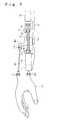
- FIG. 2is a side view showing a general configuration of a robot hand according to the first embodiment of the present invention.
- FIG. 3is a cross-sectional view of a rotation prevention mechanism for moving blocks in the robot hand according to the first embodiment of the present invention.
- FIG. 4is an exploded perspective view showing the structure of universal joints in the robot hand according to the first embodiment of the present invention.
- FIG. 5 ( a )is a diagram showing coordinates of the various points, for the purpose of explicating the drive method for a robot hand according to an embodiment of the present invention.
- FIG. 5 ( b )is a diagram showing the coordinates after a rotation about the x-axis has been made.
- FIG. 6is a diagram showing coordinates of the various points after a rotation has been made, for the purpose of explicating the drive method for a robot hand according to an embodiment of the present invention.
- FIG. 7is a perspective view showing a general configuration of a robot hand according to a second embodiment of the present invention.
- FIG. 8is a side view showing a general configuration of a robot hand according to the second embodiment of the present invention.
- FIG. 1is a perspective view showing a general configuration of a robot hand according to a first embodiment of the present invention.
- FIG. 2is a side view showing a general configuration of the robot hand according to the first embodiment of the present invention.
- 3-degrees-of-freedom universal joints UJ 1 and UJ 2are joined to the top right and left parts, respectively, of the wrist portion of the hand H 1
- a 2-degrees-of-freedom universal joint UJ 3is joined to the wrist portion of the hand H 1 so as to serve as the center of 3-degrees-of-freedom.
- the 3-degrees-of-freedom universal joints UJ 1 and UJ 2enables the hand H 1 to execute up-down swing motions D 1 and side-to-side swing motions D 2 in response to circular movements about the fulcrum axis of the 2-degrees-of-freedom universal joint UJ 3 .
- 2-degrees-of-freedom universal joint UJ 3which serves as the center of the wrist's 3-degrees-of-freedom, is able to make the hand H 1 execute twisting motions D 3 .
- a screw N 1is installed such that it is supported by the bearings BL 1 and BL 1 ′
- a screw member N 2is installed between the projecting portions T 2 and T 2 ′ such that it is supported by the bearings BL 2 and BL 2 ′.
- a moving block MB 1is provided between the projecting portions T 1 and T 1 ′, and a moving block MB 2 is provided between the projecting portions T 2 and T 2 ′.
- Screw grooves corresponding to the threads of screws N 1 and N 2are formed in moving blocks MB 1 and MB 2 , and the moving blocks MB 1 and MB 2 are connected to screws N 1 and N 2 respectively such that their screw grooves in the blocks mate with the screws' respective threads.
- each of the moving blocks MB 1 and MB 2is provided with a rotation prevention pin
- the base plate B 1has guide grooves Z 1 and Z 2 formed along the direction of movement of moving blocks MB 1 and MB 2 respectively, with the rotation prevention pins being inserted into the respective guide grooves Z 1 and Z 2 .
- FIG. 3is a cross-sectional view of a rotation prevention mechanism for the moving blocks in the robot hand according to the first embodiment of the present invention.
- a rotation prevention pin SJ 1which is in contact with the guide groove Z 1 via a bearing BL 3 .
- 2-degrees-of-freedom universal joints UJ 1 ′ and UJ 2 ′are installed to the moving blocks MB 1 and MB 2 , respectively, and these 2-degrees-of-freedom universal joints UJ 1 ′ and UJ 2 ′ are coupled to 3-degrees-of-freedom universal joints UJ 1 and UJ 2 , respectively, via connecting rods RD 1 and RD 2 .
- motors M 1 and M 2are respectively installed to the rear of the projecting portions T 1 and T 2 , which are coupled to the screws N 1 and N 2 , respectively, via couplings CP 1 and CP 2 .
- a motor M 3whose shaft JM is coupled to the 2-degrees-of-freedom universal joint UJ 3 via a reduction gear G 1 .
- motors M 1 and M 2are run in the same rotational direction, thus causing screws N 1 and N 2 to rotate in the same direction.
- each of the moving blocks MB 1 and MB 2moves linearly in the same direction along the corresponding screws N 1 and N 2 , and linear motion components of the moving blocks MB 1 and MB 2 that move in the same direction are transmitted to the 3-degrees-of-freedom universal joints UJ 1 and UJ 2 respectively via the connecting rods RD 1 and RD 2 .
- the joints UJ 1 and UJ 2enable the hand H 1 to execute up-down swing motions (D 1 ) by rotating about the horizontal axis JS of the joint UJ 3 .
- each of the moving blocks MB 1 and MB 2moves linearly in opposite directions along the corresponding screws N 1 and N 2 , and linear motion components of the moving blocks MB 1 and MB 2 that move in opposite directions are transmitted to the 3-degree-of-freedom universal joints UJ 1 and UJ 2 respectively via connecting rods RD 1 and RD 2 .
- the joints UJ 1 and UJ 2enables the hand H 1 to execute side-to-side swing motions (D 2 ) by rotating about the vertical axis JH of the joint UJ 3 .
- the moving block MB 1includes a rotation prevention pin SJ 1 which directs it along the guide groove Z 1 , thus preventing the blocks MB 1 and MB 2 from rotating.
- the top right and left end of the hand H 1are joined to the moving blocks MB 1 and MB 2 via the 3-degrees-of-freedom universal joints UJ 1 and UJ 2 and 2-degrees-of-freedom universal joints UJ 1 ′ and UJ 2 ′.
- the 3-degrees-of-freedom universal joints UJ 1 and UJ 2move on the circumference around the rotation axis JM as the hand H 1 makes a twisting rotation D 3 , it is possible to permit the 3-degrees-of-freedom universal joints UJ 1 and UJ 2 to follow the hand's twisting rotation by having the connecting rods RD 1 and RD 2 cross each other.
- the 3-degrees-of-freedom universal joints UJ 1 and UJ 2 and the 2-degrees-of-freedom universal joints UJ 1 ′, UJ 2 ′ and UJ 3are provided with stepped bearing screws which are screwed into their cruciform members via bearings, thereby simplifying their structure.
- FIG. 4is an exploded perspective view showing the structure of the universal joints in the robot hand according to the first embodiment of the present invention.
- stepped bearing screws NJ 1 , NJ 1 ′, NJ 2 and NJ 2 ′are provided respectively with steps DS 1 , DS 2 , DS 1 ′ and DS 2 ′ for receiving yokes JR 1 and JR 2 .
- the stepped bearing screws NJ 1 , NJ 1 ′, NJ 2 and NJ 2 ′are screwed through the yokes JR 1 and JR 2 into the cruciform member JB.
- the yokes JR 1 and JR 2are able to rotate about the horizontal axis JS and the vertical axis JH simply by means of the stepped bearing screws NJ 1 , NJ 1 ′, NJ 2 and NJ 2 ′ screwed into the cruciform member JB, thus making it possible to simplify the structure of the 3-degrees-of-freedom universal joints UJ 1 and UJ 2 and of the 2-degrees-of-freedom universal joints UJ 1 ′, UJ 2 ′ and UJ 3 .
- FIG. 5 ( a )is a diagram showing coordinates of the various points, for the purpose of explicating the drive method for a robot hand according to an embodiment of the present invention.
- FIG. 5 ( b )is a diagram showing the coordinates after a rotation about the x-axis has been made.
- Ois the origin (0, 0, 0)
- Cis the rotation center of the 2-degrees-of-freedom universal joint UJ 3 of FIG. 1
- Ais the center of 3-degrees-of-freedom universal joint UJ 1
- Bis the center of 3-degrees-of-freedom universal joint UJ 2
- ⁇ Xis the angle of rotation about the x-axis
- ⁇ Yis the angle of rotation about the y-axis
- ⁇ Zis the angle of rotation about the z-axis
- dis the distance between O and C
- his the distance along the z-axis between the rotation center of the 2-degrees-of-freedom universal joint UJ 3 and the centerline of the 3-degrees-of-freedom universal joints UJ 1 and UJ 2
- lis the distance along the y-axis between the rotation center of the 2-degrees-of-freedom universal joint UJ 3 and the centerline of the 3-degrees-of-freedom universal joints UJ 1 and UJ 2
- X B3d+h ⁇ sin ⁇ Y +1 ⁇ sin ⁇ Z ⁇ cos ⁇ Y (4)
- Y B3⁇ 1 ⁇ cos ⁇ X ⁇ cos ⁇ Z ⁇ ( h ⁇ cos ⁇ Y ⁇ 1 ⁇ sin ⁇ X ⁇ sin ⁇ Y ) ⁇ sin ⁇ X (5)
- Z B3⁇ 1 ⁇ cos ⁇ Z ⁇ sin ⁇ X +( h ⁇ cos ⁇ Y ⁇ 1 ⁇ sin ⁇ Z ⁇ sin ⁇ Y ) ⁇ cos ⁇ X (6)
- ⁇ Xcan be taken as equal to 0.
- X A3d+h ⁇ sin ⁇ Y ⁇ 1 ⁇ sin ⁇ Z ⁇ cos ⁇ Y (1)
- Y A31 ⁇ cos ⁇ Z (2)
- Z A3h ⁇ cos ⁇ Y +1 ⁇ sin ⁇ Z ⁇ sin ⁇ Y (3)
- FIG. 6is a diagram showing coordinates of the various points when shifted by rotations, for the purpose of explaining the drive method for a robot hand according to an embodiment of the present invention.
- Ois the origin (0, 0, 0)
- Cis the rotation center of the 2-degrees-of-freedom universal joint UJ 3 of FIG. 1
- Ais the center of 3-degrees-of-freedom universal joint UJ 1
- Bis the center of 3-degrees-of-freedom universal joint UJ 2
- ⁇ Xis the angle of rotation about the x-axis
- ⁇ Yis the angle of rotation about the y-axis
- ⁇ Zis the angle of rotation about the z-axis
- dis the distance between O and C
- his the distance along the z-axis between the rotation center of the 2-degrees-of-freedom universal joint UJ 3 and the centerline of the 3-degrees-of-freedom universal joints UJ 1 and UJ 2
- lis the distance along the y-axis between the rotation center of the 2-degrees-of-freedom universal joint UJ 3 and the centerline of the 3-degrees-of-freedom universal joints UJ 1 and UJ 2
- d 0⁇ square root over ( ) ⁇ ( d 2 +( l ⁇ l 0 ) 2 +( h ⁇ h 0 ) 2 ) (7)
- d 0 2d 2 +( l ⁇ l 0 ) 2 +( h ⁇ h 0 ) 2 (8)
- FIG. 7is a perspective view, showing the summarized configuration of a robot hand according to a second embodiment of the present invention.
- FIG. 8is a side view, showing the summarized configuration of the robot hand according to the second embodiment of the present invention.
- the twisting rotation of the wristis shifted to the elbow portion, giving just 2-degrees-of-freedom to the wrist, so that 2-degrees-of-freedom are sufficient for universal joints UJ 11 and UJ 12 located at the top right and left parts of the wrist portion.
- 2-degrees-of-freedom universal joints UJ 11 and UJ 12are joined to the top right and left parts, respectively, of the wrist portion of the hand H 1
- a 2-degrees-of-freedom universal joint UJ 13is joined to the wrist portion of the hand H 1 so as to serve as the center of 2-degrees-of-freedom.
- the 2-degrees-of-freedom universal joints UJ 11 and UJ 12enables the hand H 1 to execute up-down swing motion D 11 and side-to-side swing motion D 12 in response to circular movements about the fulcrum axis of 2-degree-of-freedom universal joint UJ 13 .
- a base plate B 11On a base plate B 11 are provided projecting portions T 11 , T 11 ′, T 12 and T 12 ′, to which bearings BL 11 , BL 11 ′, BL 12 and BL 12 ′ are installed respectively.
- a screw N 11is installed such that it is supported by the bearings BL 11 and BL 11 ′, while a screw N 12 is installed between projecting portions T 12 and T 12 ′ such that it is supported by the bearings BL 12 and BL 12 ′.
- a moving block MB 11is provided between the projecting portions T 11 and T 11 ′, and a moving block MB 12 is provided between the projecting portions T 12 and T 12 ′.
- Screw grooves corresponding to the threads of screws N 11 and N 12are formed in moving blocks MB 11 and MB 12 , and the moving blocks MB 11 and MB 12 are transpierced by screws N 11 and N 12 respectively such that their screw grooves mate with the screws' respective threads.
- each of moving blocks MB 11 and MB 12is provided with a rotation prevention pin
- the base plate B 11has guide grooves Z 11 and Z 12 formed along the direction of movement of the moving boards MB 11 and MB 12 respectively, and the rotation prevention pins are inserted into the respective guide grooves Z 11 and Z 12 .
- 2-degrees-of-freedom universal joints UJ 11 ′ and UJ 12 ′are installed to moving blocks MB 11 and MB 12 respectively, and these 2-degrees-of-freedom universal joints UJ 11 ′ and UJ 12 ′ are connected to 2-degrees-of-freedom universal joints UJ 11 and UJ 12 respectively via connecting rods RD 11 and RD 12 .
- motors M 11 and M 12are installed respectively to the rear of the projecting portions T 11 and T 12 , and the motors are coupled to the screws N 11 and N 12 respectively via couplings CP 11 and CP 12 .
- a recessed portion Uis formed for fitting a support block SB thereinto, and in extended portions UK 1 and UK 2 on either side of the recessed portion U there are provided screw holes S 1 -S 4 .
- the support block SBis for securing the baseplate B 11 and is connected to the elbow portion HJ via a fixed shaft KJ which serves as the rotation center of the support block SB.
- Ledges TN 1 and TN 2 for mounting the extended portions UK 1 and UK 2 of the base plate B 11are provided on either side of the support block SB, and screw holes S 1 ′ and S 2 ′ are provided in the ledges TN 1 and TN 2 .
- the base plate B 11When the extended portions UK 1 and UK 2 of the base plate B 11 are mounted onto the ledges TN 1 and TN 2 , the base plate B 11 can be secured to the support block SB by, for example, driving screws into the holes formed by S 1 and S 1 ′ and by S 2 and S 2 ′.
- the support block SBincludes a motor M 13 whose shaft is coupled to a gearwheel HG 2 , and a gearwheel HG 1 is installed to the fixed shaft KJ (which is connected to the elbow portion HJ) such that it meshes with the gearwheel HG 2 .
- motors M 11 and M 12are run in the same rotational direction, thus causing screws N 11 and N 12 to rotate in the same direction.
- moving blocks MB 11 and MB 12move linearly in the same direction along the screws N 11 and N 12 , and linear motion components of the moving blocks MB 11 and MB 12 that moves in the same direction are transmitted to the 2-degrees-of-freedom universal joints UJ 11 and UJ 12 respectively via connecting rods RD 11 and RD 12 .
- the joints UJ 11 and UJ 12enables the hand H 11 to execute up-down swing motion (D 11 ) by rotating about the horizontal axis JS of the joint UJ 13 .
- each moving block MB 11 and MB 12moves linearly in opposite directions along the corresponding screws N 11 and N 12 , and linear motion components of moving blocks MB 11 and MB 12 that moves in opposite direction are transmitted to the 2-degrees-of-freedom universal joints UJ 11 and UJ 12 respectively via the connecting rods RD 11 and RD 12 .
- joints UJ 11 and UJ 12Since the 2-degrees-of-freedom universal joints UJ 11 and UJ 12 are joined to the top right and left parts, respectively, of the wrist portion of the hand H 11 while the 2-degrees-of-freedom universal joint UJ 13 is joined to the wrist portion of the hand H 11 so as to serve as the center for the 2-degrees-of-freedom, joints UJ 11 and UJ 12 enables the hand H 11 to execute up-down swing motion (D 12 ) by rotating about the vertical axis JH of joint UJ 13 .
- D 12up-down swing motion
- the moving block MB 11is provided with a rotation prevention pin SJ 11 which directs it along the guide groove Z 11 , thus preventing the blocks MB 11 and MB 12 from rotating.
- the fixed shaft KJis fastened to the elbow portion HJ
- the support block SBis able to rotate about the fixed shaft KJ
- the motor M 13is fastened to the support block SB.
- the base plate B 11which is fastened to the support block SB, rotates on the circumference around the fixed shaft KJ as the support block SB rotates, causing the hand H 11 to rotate about the fixed shaft KJ.
- the base plate B 11should preferably be fastened to the support block SB such that the third universal joint UJ 13 is located on the line of the axis of the fixed shaft KJ. This will permit rotation in any desired direction around the x-, y- and z-axes even when the mechanism for wrist rotation is shifted to the elbow portion.
- the third universal joint UJ 13may be made to lie on the line of the axis of the fixed shaft KJ when the baseplate B 11 is fastened to the support block SB by, for example, installing the ledges TN 1 and TN 2 to the support block at an inclined angle.
- the mechanism for wrist rotationis shifted to the elbow portion, giving just 2-degrees-of-freedom to the wrist and thereby permitting the manipulation unit to be even more compact and to have a simpler control.
- linear motorscould alternatively be used to drive the universal joints UJ 1 and UJ 2 (or UJ 11 and UJ 12 ).
- potentiometers, encoders, linear sensors or the likemay be used to measure amounts of rotational and/or linear motions of the actuators, and potentiometers or encoders may be used to measure rotation angles of the universal joints.
- the rotation centers of the 3-degrees-of-freedomcan be made to coincide at a single point while keeping the rotational axes orthogonal to each other, thereby making it possible to perform movement operations easily and to make a manipulation unit more lightweight and more compact.
Landscapes
- Engineering & Computer Science (AREA)
- Health & Medical Sciences (AREA)
- Mechanical Engineering (AREA)
- Robotics (AREA)
- Orthopedic Medicine & Surgery (AREA)
- Transplantation (AREA)
- General Engineering & Computer Science (AREA)
- Vascular Medicine (AREA)
- Heart & Thoracic Surgery (AREA)
- Life Sciences & Earth Sciences (AREA)
- Animal Behavior & Ethology (AREA)
- General Health & Medical Sciences (AREA)
- Public Health (AREA)
- Veterinary Medicine (AREA)
- Biomedical Technology (AREA)
- Oral & Maxillofacial Surgery (AREA)
- Cardiology (AREA)
- Manipulator (AREA)
Abstract
Description
1. Field of the Invention
The present invention relates to manipulation units and is particularly suited to application in robot hands, manipulators and the like.
2. Description of the Related Art
Industrial robots have conventionally been equipped with a securing/gripping hand utilizing parallel link mechanisms, such as described for instance in Laid-Open Japanese Patent Application No. 9-285874. Further, there have been humanoid robots having a single-point intersection type wrist mechanism allowing the 3 axes of the wrist joint to intersect at a single point by means of gearwheels, as described in the Robot Handbook (Corona Publications).
However, securing/gripping hands utilizing parallel link mechanisms have suffered from the problem that they could not permit 3-degrees-of-freedom because they were joined to an arm with only one or 2-degrees-of-freedom, and this has rendered precision control of their positioning time-consuming.
Further, the method of using gearwheels to realize the single-point intersection type wrist mechanism has rendered the mechanisms more complicated, which has not only prevented the mechanism from being more lightweight and more compact, but also resulted in the additional problem that operation calculations posed difficulties since the rotational axes are not orthogonal to each other.
Accordingly the object of the present invention is to provide a manipulation unit in which the rotation centers of the 3-degrees-of-freedom can be made to coincide at a single point while keeping the rotational axes orthogonal to each other.
In order to attain the aforesaid object, the invention according to provides a manipulation unit having first and second universal joints that allow up-down and side-to-side swing motions to be made in response to linear motions, and a third universal joint that serves as the center of 3-degrees-of-freedom and execute twisting rotation. This makes it possible to have the rotation centers of 3-degrees-of-freedom coincided at a single point, with the rotational axes kept orthogonal to each other, thus making it possible to make the manipulation unit more lightweight and more compact and permitting kinematical coordinate calculations, so that agile and precise positioning control can be implemented.
The invention also provides a manipulation unit having a first linear actuator that moves the first universal joint in linear motion, a second linear actuator that moves the second universal joint in linear motion, and a rotation motor that rotates the third universal joint. This enables a linear motion of the first and second universal joints and a rotation of the third universal joint, without increasing the mechanism's complexity, thus making it possible to make the manipulation unit more lightweight and more compact.
The invention further provides a manipulation unit additionally having a first drive control means that drives the first and second linear actuators in the same direction so that it corresponds to an up-down swing motion, and a second drive control means that drives the first and second linear actuators in opposite directions so that it corresponds to a side-to-side swing motion.
Accordingly, simple drive control by itself makes up-down and side-to-side swing motions possible, thus permitting simpler computational processing for operational motion and agile and precise positioning control.
The invention, in addition, provides a manipulation unit, wherein the first linear actuator includes a first moving block which connects to the first universal joint via a first connecting rod and in which a first screw groove is cut, a first screw member which is fitted into the first screw groove, and a first motor which rotates the first screw member; and the second linear actuator includes a second moving block which is connected to the second universal joint and into which a second screw groove is cut, a second screw member which is fitted into the second screw groove, and a second motor which rotates the second screw member.
This makes it possible to make up-down and side-to-side swing motions using rotation motors, thus making it possible to make the manipulator unit more compact and less expensive.
The invention also provides a manipulation unit having a first guide groove formed in the direction of the axis of the first screw member and a first projecting portion which is inserted into the first guide groove and is joined to the first moving block, a second guide groove formed in the direction of the axis of the second screw member and a second projecting portion which is inserted into the second guide groove and is joined to the second moving block.
In this way, the moving blocks are moved by engaging with the screw member and therefore they do not rotate, so that the blocks move in linear motion only, thus permitting fine precision positioning of the first and second universal joints.
The invention further provides a manipulation unit, wherein the projecting portions is in contact with the guide grooves via bearings.
This makes it possible to reduce friction between the projecting portions and the guide grooves even when the former comes into contact with the latter, thus permitting smooth execution of linear motion of the moving blocks.
The invention also provides a manipulation unit, wherein the universal joints have stepped bearing screws screwed into the cruciform member through the bearings. This makes it possible to install the bearings to the cruciform member simply by screwing the stepped bearing screws into the cruciform member through the bearings, and to have the bearings rotate around the bearing stepped screws, thus permitting a simpler mechanism for the universal joints.
The invention further provides a manipulation unit having first and second universal joints that allow up-down and side-to-side swing motions to be made in response to linear motion, a third universal joint that serves as the center of 2-degrees-of-freedom and enables twisting rotations, and a rotation means that rotates the first and second universal joints around fixed axes.
This makes it possible to separate the part by which twisting rotation are executed from the part by which up-down and side-to-side swing movements are executed; thus the need to deploy the mechanism for making twisting rotations in the part by which up-down and side-to-side swing movements are executed is eliminated, thereby making it possible to make the manipulation unit more compact and to achieve more simplified control.
The invention also provides a manipulation unit having first and second universal joints that enable up-down and side-to-side swing movements to be made in response to linear motions, a third universal joint that serves as the center of 2-degrees-of-freedom and enables twisting rotations, a first linear actuator which moves the first universal joint in linear motion, a second linear actuator which moves the second universal joint in linear motion, fastening blocks which hold the first, second and third universal joints and the first and second linear actuators securely, a support block which supports the fixing blocks, bearings which support the support block such that it is able to rotate around a fixed shaft, a rotation motor which is installed in the support block, and gearwheels which transmit the rotational force of the rotation motor to the fixed shaft.
This enables the first and second universal joints to rotate on the circumference around the fixed shaft at an angle relative to it, so that positioning control can be implemented with ease even in cases where the part by which twisting rotations are executed is separated from the part by which up-down and side-to-side swing movements are executed.
The invention further provides a manipulation unit, wherein the fastening blocks are fastened to the support block such that the third universal joint is located on the line of the fixed shaft's axis.
This enables a rotation around the X, Y and Z axes in any desired direction, even in cases where the part by which a twisting rotation is executed is separated from the part by which up-down and side-to-side swing movements are executed.
FIG.5(a) is a diagram showing coordinates of the various points, for the purpose of explicating the drive method for a robot hand according to an embodiment of the present invention. FIG.5(b) is a diagram showing the coordinates after a rotation about the x-axis has been made.
Preferred embodiments of the manipulation unit according to the present invention are described below, using a robot hand as an example.
InFIGS. 1 and 2 , 3-degrees-of-freedom universal joints UJ1 and UJ2 are joined to the top right and left parts, respectively, of the wrist portion of the hand H1, and a 2-degrees-of-freedom universal joint UJ3 is joined to the wrist portion of the hand H1 so as to serve as the center of 3-degrees-of-freedom.
The 3-degrees-of-freedom universal joints UJ1 and UJ2 enables the hand H1 to execute up-down swing motions D1 and side-to-side swing motions D2 in response to circular movements about the fulcrum axis of the 2-degrees-of-freedom universal joint UJ3. Further, 2-degrees-of-freedom universal joint UJ3, which serves as the center of the wrist's 3-degrees-of-freedom, is able to make the hand H1 execute twisting motions D3.
On the baseplate B1 are provided projecting portions T1, T1′, T2 and T2′, to which bearings BL1, BL1′, BL2 and BL2′ are installed respectively.
Between the projecting portions T1 and T1′ a screw N1 is installed such that it is supported by the bearings BL1 and BL1′, while a screw member N2 is installed between the projecting portions T2 and T2′ such that it is supported by the bearings BL2 and BL2′.
A moving block MB1 is provided between the projecting portions T1 and T1′, and a moving block MB2 is provided between the projecting portions T2 and T2′. Screw grooves corresponding to the threads of screws N1 and N2 are formed in moving blocks MB1 and MB2, and the moving blocks MB1 and MB2 are connected to screws N1 and N2 respectively such that their screw grooves in the blocks mate with the screws' respective threads.
Further, each of the moving blocks MB1 and MB2 is provided with a rotation prevention pin, and the base plate B1 has guide grooves Z1 and Z2 formed along the direction of movement of moving blocks MB1 and MB2 respectively, with the rotation prevention pins being inserted into the respective guide grooves Z1 and Z2.
At the bottom of the moving block MB1 inFIG. 3 , for example, there is provided a rotation prevention pin SJ1 which is in contact with the guide groove Z1 via a bearing BL3.
2-degrees-of-freedom universal joints UJ1′ and UJ2′ are installed to the moving blocks MB1 and MB2, respectively, and these 2-degrees-of-freedom universal joints UJ1′ and UJ2′ are coupled to 3-degrees-of-freedom universal joints UJ1 and UJ2, respectively, via connecting rods RD1 and RD2.
On the base plate B1, motors M1 and M2 are respectively installed to the rear of the projecting portions T1 and T2, which are coupled to the screws N1 and N2, respectively, via couplings CP1 and CP2.
Further, towards the forward end of the base plate B1 is installed a motor M3, whose shaft JM is coupled to the 2-degrees-of-freedom universal joint UJ3 via a reduction gear G1.
Next is described the operation of the robot hand inFIGS. 1 and 2 .
In order to make the hand H1 execute up-down swing motion D1, motors M1 and M2 are run in the same rotational direction, thus causing screws N1 and N2 to rotate in the same direction.
When this happens, each of the moving blocks MB1 and MB2 moves linearly in the same direction along the corresponding screws N1 and N2, and linear motion components of the moving blocks MB1 and MB2 that move in the same direction are transmitted to the 3-degrees-of-freedom universal joints UJ1 and UJ2 respectively via the connecting rods RD1 and RD2.
Since the 3-degrees-of-freedom universal joints UJ1 and UJ2 are joined to the top right and left parts, respectively, of the wrist portion of the hand H1 while the 2-degrees-of-freedom universal joints UJ3 is installed to the wrist portion of the hand H1 so as to serve as the center for the 3-degrees-of-freedom, the joints UJ1 and UJ2 enable the hand H1 to execute up-down swing motions (D1) by rotating about the horizontal axis JS of the joint UJ3.
In order to make the hand H1 execute side-to-side swing motions D2, the motors M1 and M2 are run in opposite rotational directions, thus causing the screws N1 and N2 to rotate in opposite directions.
When this happens, each of the moving blocks MB1 and MB2 moves linearly in opposite directions along the corresponding screws N1 and N2, and linear motion components of the moving blocks MB1 and MB2 that move in opposite directions are transmitted to the 3-degree-of-freedom universal joints UJ1 and UJ2 respectively via connecting rods RD1 and RD2.
Since the 3-degrees-of-freedom universal joints UJ1 and UJ2 are joined to the top right and left parts, respectively, of the wrist portion of the hand H1 while the 2-degrees-of-freedom universal joint UJ3 is joined to the wrist portion of the hand H1 so as to serve as the center for the 3-degrees-of-freedom, the joints UJ1 and UJ2 enables the hand H1 to execute side-to-side swing motions (D2) by rotating about the vertical axis JH of the joint UJ3.
In order to convert a rotational motion of the screws N1 and N2 into a linear motion of the moving blocks MB1 and MB2, the latter must be prevented from rotating together with the screws. This can be accomplished by providing the blocks with rotation prevention pins. For example, the moving block MB1 includes a rotation prevention pin SJ1 which directs it along the guide groove Z1, thus preventing the blocks MB1 and MB2 from rotating.
In order to make the hand H1 execute twisting rotation D3, the motor M3 is run, thus causing the 2-degrese-of-freedom universal joint UJ3 to rotate about the shaft JM of the motor M3.
When this happens, the hand H1 rotates about the shaft (rotational axis) JM, as the 2-degrees-of-freedom universal joint UJ3 rotates. In this way, a twisting rotation D3 of the hand H1 is executed.
The top right and left end of the hand H1 are joined to the moving blocks MB1 and MB2 via the 3-degrees-of-freedom universal joints UJ1 and UJ2 and 2-degrees-of-freedom universal joints UJ1′ and UJ2′. Thus, even when the 3-degrees-of-freedom universal joints UJ1 and UJ2 move on the circumference around the rotation axis JM as the hand H1 makes a twisting rotation D3, it is possible to permit the 3-degrees-of-freedom universal joints UJ1 and UJ2 to follow the hand's twisting rotation by having the connecting rods RD1 and RD2 cross each other.
Thus the provision of the 3-degree-of-freedom universal joints UJ1 and UJ2 and the 2-degree-of-freedom universal joint UJ3 at the wrist portion makes it possible to have the rotation centers of the 3-degrees-of-freedom coincide at a single point, while keeping the three rotational axes JH, JS and JM orthogonal to each other.
This means that wrist movements of 3 degrees of freedom (up-down swing motion D1, side-to-side swing motion D2 and twisting rotation D3) can be executed merely by implementing simple drive control of the motors M1-M3, with the result that the computational processing for operation can be simplified, and agile and precise positioning control can be implemented.
Furthermore, the 3-degrees-of-freedom universal joints UJ1 and UJ2 and the 2-degrees-of-freedom universal joints UJ1′, UJ2′ and UJ3 are provided with stepped bearing screws which are screwed into their cruciform members via bearings, thereby simplifying their structure.
InFIG. 4 , stepped bearing screws NJ1, NJ1′, NJ2 and NJ2′ are provided respectively with steps DS1, DS2, DS1′ and DS2′ for receiving yokes JR1 and JR2.
The stepped bearing screws NJ1, NJ1′, NJ2 and NJ2′ are screwed through the yokes JR1 and JR2 into the cruciform member JB.
Because of this arrangement, the yokes JR1 and JR2 are able to rotate about the horizontal axis JS and the vertical axis JH simply by means of the stepped bearing screws NJ1, NJ1′, NJ2 and NJ2′ screwed into the cruciform member JB, thus making it possible to simplify the structure of the 3-degrees-of-freedom universal joints UJ1 and UJ2 and of the 2-degrees-of-freedom universal joints UJ1′, UJ2′ and UJ3.
FIG.5(a) is a diagram showing coordinates of the various points, for the purpose of explicating the drive method for a robot hand according to an embodiment of the present invention. FIG.5(b) is a diagram showing the coordinates after a rotation about the x-axis has been made.
InFIG. 5 , O is the origin (0, 0, 0), C is the rotation center of the 2-degrees-of-freedom universal joint UJ3 ofFIG. 1 , A is the center of 3-degrees-of-freedom universal joint UJ1, B is the center of 3-degrees-of-freedom universal joint UJ2, θXis the angle of rotation about the x-axis, θYis the angle of rotation about the y-axis, θZis the angle of rotation about the z-axis, d is the distance between O and C, h is the distance along the z-axis between the rotation center of the 2-degrees-of-freedom universal joint UJ3 and the centerline of the 3-degrees-of-freedom universal joints UJ1 and UJ2, l is the distance along the y-axis between the rotation center of the 2-degrees-of-freedom universal joint UJ3 and the centerline of the 3-degrees-of-freedom universal joints UJ1 and UJ2, A′ is the point to which point A is rotated ({circle around (1)}) by θX, A″ is the point to which point A″ is rotated ({circle around (2)}) by θY, and A′″ is the point to which point A″ is rotated ({circle around (3)}) by θZ.
The coordinates of point C (Xc, Yc, Zc) are equal to (d, 0, 0), while those of point A3(XA3, YA3, ZA3) are given by:
XA3=d+h×sin θY−1×sin θZ×cos θY (1)
YA3=1×cos θX×cos θZ−(h×cos θY+1×sin θZ×sin θY)×sin θX (2)
ZA3=1×cos θZ×sin θX+(h×cos θY+1×sin θZ×sin θY)×cos θX (3)
XA3=d+h×sin θY−1×sin θZ×cos θY (1)
YA3=1×cos θX×cos θZ−(h×cos θY+1×sin θZ×sin θY)×sin θX (2)
ZA3=1×cos θZ×sin θX+(h×cos θY+1×sin θZ×sin θY)×cos θX (3)
The coordinates of point B3 (XB3, YB3, ZB3) are given by:
XB3=d+h×sin θY+1×sin θZ×cos θY (4)
YB3=−1×cos θX×cos θZ−(h×cos θY−1×sin θX×sin θY)×sin θX (5)
ZB3=−1×cos θZ×sin θX+(h×cos θY−1×sin θZ×sin θY)×cos θX (6)
XB3=d+h×sin θY+1×sin θZ×cos θY (4)
YB3=−1×cos θX×cos θZ−(h×cos θY−1×sin θX×sin θY)×sin θX (5)
ZB3=−1×cos θZ×sin θX+(h×cos θY−1×sin θZ×sin θY)×cos θX (6)
In cases where a twisting rotation of the wrist is shifted to the elbow portion, giving just 2-degrees-of-freedom to the wrist, θXcan be taken as equal to 0. As a result, the coordinates of point A3(XA3, YA3, ZA3) will be given by:
XA3=d+h×sin θY−1×sin θZ×cos θY (1)
YA3=1×cos θZ (2)
ZA3=h×cos θY+1×sin θZ×sin θY (3)
XA3=d+h×sin θY−1×sin θZ×cos θY (1)
YA3=1×cos θZ (2)
ZA3=h×cos θY+1×sin θZ×sin θY (3)
And the coordinates of point B3(XB3, YB3, ZB3) in this case will be given by:
XB3=d+h×sin θY+1×sin θZ×cos θY (4)
YB3=−1×cos θZ (5)
ZB3=h×cos θY−1×sin θZ×sin θY (6)
XB3=d+h×sin θY+1×sin θZ×cos θY (4)
YB3=−1×cos θZ (5)
ZB3=h×cos θY−1×sin θZ×sin θY (6)
As a result, calculation can be simplified by shifting twisting rotation of the wrist to the elbow portion.
InFIG. 6 , O is the origin (0, 0, 0), C is the rotation center of the 2-degrees-of-freedom universal joint UJ3 ofFIG. 1 , A is the center of 3-degrees-of-freedom universal joint UJ1, B is the center of 3-degrees-of-freedom universal joint UJ2, θXis the angle of rotation about the x-axis, θYis the angle of rotation about the y-axis, θZis the angle of rotation about the z-axis, d is the distance between O and C, h is the distance along the z-axis between the rotation center of the 2-degrees-of-freedom universal joint UJ3 and the centerline of the 3-degrees-of-freedom universal joints UJ1 and UJ2, l is the distance along the y-axis between the rotation center of the 2-degrees-of-freedom universal joint UJ3 and the centerline of the 3-degrees-of-freedom universal joints UJ1 and UJ2, do is the length of the connecting rods RD1 and RD2, ho is the distance along the z-axis between the origin O and the moving blocks MB1 and MB2, l0is the distance along the y-axis between the origin O and the moving blocks MB1 and MB2, A1is the point to which point A is rotated about the x-axis by θX, A2is the point to which point A1is rotated about the y-axis by θY, A3is the point to which point A2is rotated about the x-axis by θZ, B1is the point to which point B is rotated about the x-axis by θX, B2is the point to which point B1is rotated about the y-axis by θY, B3is the point to which point B2is rotated about the x-axis by θZ, and SAand SBare the distances moved by the moving blocks MB1 and MB2 respectively.
The following equation is given:
d0=√{square root over ( )}(d2+(l−l0)2+(h−h0)2) (7)
Hence,
d02=d2+(l−l0)2+(h−h0)2 (8)
d0=√{square root over ( )}(d2+(l−l0)2+(h−h0)2) (7)
Hence,
d02=d2+(l−l0)2+(h−h0)2 (8)
The following equation is also given:
(XA3−SA)2+(YA3−l0)2+(ZA3−h0)2=d02 (9)
Hence,
SA=XA3−√{square root over ( )}(d02−(YA3−l0)2−(ZA3−h0)2)(10)
Similarly,
(XB3−SB)2+(YB3−l0)2+(ZB3−h0)2=d02 (11)
Hence,
SB=XB3−{square root over ( )}(d02−(YB3−l0)2−(ZB3−h0)2)(12)
(XA3−SA)2+(YA3−l0)2+(ZA3−h0)2=d02 (9)
Hence,
SA=XA3−√{square root over ( )}(d02−(YA3−l0)2−(ZA3−h0)2)(10)
Similarly,
(XB3−SB)2+(YB3−l0)2+(ZB3−h0)2=d02 (11)
Hence,
SB=XB3−{square root over ( )}(d02−(YB3−l0)2−(ZB3−h0)2)(12)
Consequently, when the angles of rotation θX, θY, and θZof the hand H1 about the x-, y- and z-axes respectively are given, the distance moved by the moving blocks MB1 and MB2 can be worked out by calculating the coordinates of point A3(XA3, YA3, ZA3) and of point B3(XB3, YB3, ZB3) according to equations (1) through (6) and substituting the resulting values in equations (10) and (11).
This means that drive control of each motor M1 and M2 can be implemented on the basis of kinematical coordinate calculations, thus permitting agile and precise positioning control.
InFIGS. 7 and 8 , 2-degrees-of-freedom universal joints UJ11 and UJ12 are joined to the top right and left parts, respectively, of the wrist portion of the hand H1, and a 2-degrees-of-freedom universal joint UJ13 is joined to the wrist portion of the hand H1 so as to serve as the center of 2-degrees-of-freedom.
The 2-degrees-of-freedom universal joints UJ11 and UJ12 enables the hand H1 to execute up-down swing motion D11 and side-to-side swing motion D12 in response to circular movements about the fulcrum axis of 2-degree-of-freedom universal joint UJ13.
On a base plate B11 are provided projecting portions T11, T11′, T12 and T12′, to which bearings BL11, BL11′, BL12 and BL12′ are installed respectively.
Between the projecting portions T11 and T11′ a screw N11 is installed such that it is supported by the bearings BL11 and BL11′, while a screw N12 is installed between projecting portions T12 and T12′ such that it is supported by the bearings BL12 and BL12′.
A moving block MB11 is provided between the projecting portions T11 and T11′, and a moving block MB12 is provided between the projecting portions T12 and T12′. Screw grooves corresponding to the threads of screws N11 and N12 are formed in moving blocks MB11 and MB12, and the moving blocks MB11 and MB12 are transpierced by screws N11 and N12 respectively such that their screw grooves mate with the screws' respective threads.
Further, each of moving blocks MB11 and MB12 is provided with a rotation prevention pin, the base plate B11 has guide grooves Z11 and Z12 formed along the direction of movement of the moving boards MB11 and MB12 respectively, and the rotation prevention pins are inserted into the respective guide grooves Z11 and Z12.
2-degrees-of-freedom universal joints UJ11′ and UJ12′ are installed to moving blocks MB11 and MB12 respectively, and these 2-degrees-of-freedom universal joints UJ11′ and UJ12′ are connected to 2-degrees-of-freedom universal joints UJ11 and UJ12 respectively via connecting rods RD11 and RD12.
On the baseplate B11, motors M11 and M12 are installed respectively to the rear of the projecting portions T11 and T12, and the motors are coupled to the screws N11 and N12 respectively via couplings CP11 and CP12.
Further, at the rear end of the baseplate B11, a recessed portion U is formed for fitting a support block SB thereinto, and in extended portions UK1 and UK2 on either side of the recessed portion U there are provided screw holes S1-S4.
The support block SB is for securing the baseplate B11 and is connected to the elbow portion HJ via a fixed shaft KJ which serves as the rotation center of the support block SB.
Ledges TN1 and TN2 for mounting the extended portions UK1 and UK2 of the base plate B11 are provided on either side of the support block SB, and screw holes S1′ and S2′ are provided in the ledges TN1 and TN2.
When the extended portions UK1 and UK2 of the base plate B11 are mounted onto the ledges TN1 and TN2, the base plate B11 can be secured to the support block SB by, for example, driving screws into the holes formed by S1 and S1′ and by S2 and S2′.
Further, the support block SB includes a motor M13 whose shaft is coupled to a gearwheel HG2, and a gearwheel HG1 is installed to the fixed shaft KJ (which is connected to the elbow portion HJ) such that it meshes with the gearwheel HG2.
Next is described the operation of the robot hand inFIGS. 7 and 8 .
In order to make the hand H11 execute up-down swing motions D11, motors M11 and M12 are run in the same rotational direction, thus causing screws N11 and N12 to rotate in the same direction.
When this happens, moving blocks MB11 and MB12 move linearly in the same direction along the screws N11 and N12, and linear motion components of the moving blocks MB11 and MB12 that moves in the same direction are transmitted to the 2-degrees-of-freedom universal joints UJ11 and UJ12 respectively via connecting rods RD11 and RD12.
Since the 2-degrees-of-freedom universal joints UJ11 and UJ12 are joined to the top right and left parts, respectively, of the wrist portion of the hand H11 while the 2-degrees-of-freedom universal joint UJ13 is joined to the wrist portion of the hand H11 so as to serve as the center for the 2-degrees-of-freedom, the joints UJ11 and UJ12 enables the hand H11 to execute up-down swing motion (D11) by rotating about the horizontal axis JS of the joint UJ13.
In order to make the hand H11 execute side-to-side swing motions D12, the motors M11 and M12 are run in opposite rotational directions, thus causing the screws N11 and N12 to rotate in opposite directions.
When this happens, each moving block MB11 and MB12 moves linearly in opposite directions along the corresponding screws N11 and N12, and linear motion components of moving blocks MB11 and MB12 that moves in opposite direction are transmitted to the 2-degrees-of-freedom universal joints UJ11 and UJ12 respectively via the connecting rods RD11 and RD12.
Since the 2-degrees-of-freedom universal joints UJ11 and UJ12 are joined to the top right and left parts, respectively, of the wrist portion of the hand H11 while the 2-degrees-of-freedom universal joint UJ13 is joined to the wrist portion of the hand H11 so as to serve as the center for the 2-degrees-of-freedom, joints UJ11 and UJ12 enables the hand H11 to execute up-down swing motion (D12) by rotating about the vertical axis JH of joint UJ13.
In order to convert rotational motions of the screws N11 and N12 into linear motions of the moving blocks MB11 and MB12, the latter must be prevented from rotating together with the screws. This can be accomplished by providing the blocks with rotation prevention pins. For example, the moving block MB11 is provided with a rotation prevention pin SJ11 which directs it along the guide groove Z11, thus preventing the blocks MB11 and MB12 from rotating.
And in order to execute rotations D13 of the hand H11, the motor M13 is run, so as to rotate the gearwheel HG2.
Thereupon the rotational force of the gearwheel HG2 is transmitted to the gearwheel HG1. However, the gearwheel HG1 is fastened to the fixed shaft KJ, so the gearwheel HG2 is subjected to reaction from the gearwheel HG1. This causes the gearwheel HG2 to rotate around the circumference of the gearwheel HG1, thereby effecting twisting rotation of the entire arm up to the elbow portion HJ.
That is, the fixed shaft KJ is fastened to the elbow portion HJ, the support block SB is able to rotate about the fixed shaft KJ, and the motor M13 is fastened to the support block SB.
As a result, when the gearwheel HG2 turns, it rotates along the circumference of the gearwheel HG1 because the latter is fastened to the fixed shaft KJ, whereby the support block SB and the motor M13 rotate as an integrated whole around the circumference of the fixed shaft KJ.
Therefore the base plate B11, which is fastened to the support block SB, rotates on the circumference around the fixed shaft KJ as the support block SB rotates, causing the hand H11 to rotate about the fixed shaft KJ.
The base plate B11 should preferably be fastened to the support block SB such that the third universal joint UJ13 is located on the line of the axis of the fixed shaft KJ. This will permit rotation in any desired direction around the x-, y- and z-axes even when the mechanism for wrist rotation is shifted to the elbow portion.
The third universal joint UJ13 may be made to lie on the line of the axis of the fixed shaft KJ when the baseplate B11 is fastened to the support block SB by, for example, installing the ledges TN1 and TN2 to the support block at an inclined angle.
This makes it possible to secure the baseplate B11 to the support block SB simply by mounting the extended portions UK1 and UK2 of the base plate B11 onto the ledges TN1 and TN2 so that the third universal joints UJ13 will be positioned onto the axis of line of the fixed shaft KJ.
Thus, according to the second embodiment described above, the mechanism for wrist rotation is shifted to the elbow portion, giving just 2-degrees-of-freedom to the wrist and thereby permitting the manipulation unit to be even more compact and to have a simpler control.
In the foregoing descriptions of embodiments it is assumed that the method for making the universal joints UJ1 and UJ2 (or UJ11 and UJ12) execute circular rotation motions about universal joint UJ3 (or UJ13) uses the motors M1 and M2 (or M11 and M12) and the screws N1 and N2 (or N11 and N12), but another rotational-to-linear motion conversion mechanism such as rack-and-pinion could alternatively be used instead of the screws.
Further, linear motors could alternatively be used to drive the universal joints UJ1 and UJ2 (or UJ11 and UJ12).
Additionally, where operational positions are measured to apply control, potentiometers, encoders, linear sensors or the like may be used to measure amounts of rotational and/or linear motions of the actuators, and potentiometers or encoders may be used to measure rotation angles of the universal joints.
Further, although the foregoing descriptions of the embodiments are given taking an application of the invention to a robot arm as an example, it may also be applied to the elbow, shoulder, neck or other joints of a robot, to mechanisms for motion of a robot's eye, to the joints of a manipulator, or to the platforms for an omnidirectional projector and a tracking camera, and so on.
As the foregoing has described, according to the present invention, the rotation centers of the 3-degrees-of-freedom can be made to coincide at a single point while keeping the rotational axes orthogonal to each other, thereby making it possible to perform movement operations easily and to make a manipulation unit more lightweight and more compact. These advantages yield the further advantage of agile and precise control of positioning.
The entire disclosure of Japanese Application No. 2001-367328 filed Nov. 30, 2001 is incorporated by reference herein.
Claims (1)
1. A manipulation unit comprising:
first and second universal joints that allow up-down and side-to-side swing motions to be made in response to linear motions,
a third universal joint that serves as the center of 2-degrees-of-freedom and enables twisting rotations,
a rotation means that rotates the first and second universal joints around a fixed shaft,
a first linear actuator which moves the first universal joint in linear motion,
a second linear actuator which moves the second universal joint in linear motion,
fastening blocks which hold the first, second and third universal joints and the first and second linear actuators securely,
a support block which supports the fastening blocks,
bearing units which support the supports block such that it is able to rotate around said fixed shaft,
a rotation motor which is installed in the support block, and
gearwheels which transmit a rotational force of the rotation motor to the fixed shaft,
wherein the fastening blocks are fastened to the support block such that the third universal joint is located on a line of the fixed shaft's axis.
Applications Claiming Priority (2)
| Application Number | Priority Date | Filing Date | Title |
|---|---|---|---|
| JP2001-367328 | 2001-11-30 | ||
| JP2001367328AJP2003170381A (en) | 2001-11-30 | 2001-11-30 | Operation device |
Publications (2)
| Publication Number | Publication Date |
|---|---|
| US20030101838A1 US20030101838A1 (en) | 2003-06-05 |
| US6860169B2true US6860169B2 (en) | 2005-03-01 |
Family
ID=19177091
Family Applications (1)
| Application Number | Title | Priority Date | Filing Date |
|---|---|---|---|
| US10/261,171Expired - Fee RelatedUS6860169B2 (en) | 2001-11-30 | 2002-09-30 | Manipulation unit |
Country Status (2)
| Country | Link |
|---|---|
| US (1) | US6860169B2 (en) |
| JP (1) | JP2003170381A (en) |
Cited By (206)
| Publication number | Priority date | Publication date | Assignee | Title |
|---|---|---|---|---|
| US20030192391A1 (en)* | 2002-04-11 | 2003-10-16 | Fanuc Ltd. | Wrist driving mechanism for robot |
| US20090308188A1 (en)* | 2008-06-11 | 2009-12-17 | Samsung Electronics Co., Ltd. | Robot joint driving apparatus and robot having the same |
| US20100229669A1 (en)* | 2009-03-16 | 2010-09-16 | Korea Advanced Institute Of Science And Technology | Manipulator with distributed actuation mechanism |
| US8676382B2 (en) | 2010-05-26 | 2014-03-18 | GM Global Technology Operations LLC | Applying workspace limitations in a velocity-controlled robotic mechanism |
| TWI644766B (en)* | 2017-11-15 | 2018-12-21 | 國立成功大學 | Joint module and multi-joint modular machine arm |
| US20200009746A1 (en)* | 2018-07-03 | 2020-01-09 | Swift Engineering, Inc. | Robotic forearms |
| US10814478B2 (en) | 2017-12-15 | 2020-10-27 | National Cheng Kung University | Joint module and multi-joint modular robot arm |
| US20210331310A1 (en)* | 2020-04-28 | 2021-10-28 | Ubtech Robotics Corp Ltd | Neck mechanism for robot |
| US11464654B2 (en) | 2014-02-04 | 2022-10-11 | Rehabilitation Institute Of Chicago | Modular and lightweight myoelectric prosthesis components and related methods |
| US11553916B2 (en) | 2015-09-30 | 2023-01-17 | Cilag Gmbh International | Compressible adjunct with crossing spacer fibers |
| US11559302B2 (en) | 2007-06-04 | 2023-01-24 | Cilag Gmbh International | Surgical instrument including a firing member movable at different speeds |
| US11564682B2 (en) | 2007-06-04 | 2023-01-31 | Cilag Gmbh International | Surgical stapler device |
| US11571207B2 (en) | 2014-12-18 | 2023-02-07 | Cilag Gmbh International | Surgical system including lateral supports for a flexible drive member |
| US11576672B2 (en) | 2019-12-19 | 2023-02-14 | Cilag Gmbh International | Surgical instrument comprising a closure system including a closure member and an opening member driven by a drive screw |
| US11576673B2 (en) | 2005-08-31 | 2023-02-14 | Cilag Gmbh International | Stapling assembly for forming staples to different heights |
| US11583279B2 (en) | 2008-10-10 | 2023-02-21 | Cilag Gmbh International | Powered surgical cutting and stapling apparatus with manually retractable firing system |
| US11602340B2 (en) | 2010-09-30 | 2023-03-14 | Cilag Gmbh International | Adhesive film laminate |
| US11612393B2 (en) | 2006-01-31 | 2023-03-28 | Cilag Gmbh International | Robotically-controlled end effector |
| US11612395B2 (en) | 2008-02-14 | 2023-03-28 | Cilag Gmbh International | Surgical system including a control system having an RFID tag reader |
| US11612394B2 (en) | 2011-05-27 | 2023-03-28 | Cilag Gmbh International | Automated end effector component reloading system for use with a robotic system |
| US11617575B2 (en) | 2008-09-23 | 2023-04-04 | Cilag Gmbh International | Motor-driven surgical cutting instrument |
| US11617577B2 (en) | 2020-10-29 | 2023-04-04 | Cilag Gmbh International | Surgical instrument comprising a sensor configured to sense whether an articulation drive of the surgical instrument is actuatable |
| US11622785B2 (en) | 2006-09-29 | 2023-04-11 | Cilag Gmbh International | Surgical staples having attached drivers and stapling instruments for deploying the same |
| US11622763B2 (en) | 2013-04-16 | 2023-04-11 | Cilag Gmbh International | Stapling assembly comprising a shiftable drive |
| US11627959B2 (en) | 2019-06-28 | 2023-04-18 | Cilag Gmbh International | Surgical instruments including manual and powered system lockouts |
| US11627960B2 (en) | 2020-12-02 | 2023-04-18 | Cilag Gmbh International | Powered surgical instruments with smart reload with separately attachable exteriorly mounted wiring connections |
| US11638587B2 (en) | 2019-06-28 | 2023-05-02 | Cilag Gmbh International | RFID identification systems for surgical instruments |
| US11642128B2 (en) | 2017-06-28 | 2023-05-09 | Cilag Gmbh International | Method for articulating a surgical instrument |
| US11642125B2 (en) | 2016-04-15 | 2023-05-09 | Cilag Gmbh International | Robotic surgical system including a user interface and a control circuit |
| US11648005B2 (en) | 2008-09-23 | 2023-05-16 | Cilag Gmbh International | Robotically-controlled motorized surgical instrument with an end effector |
| US11648008B2 (en) | 2006-01-31 | 2023-05-16 | Cilag Gmbh International | Surgical instrument having force feedback capabilities |
| US11653914B2 (en) | 2017-06-20 | 2023-05-23 | Cilag Gmbh International | Systems and methods for controlling motor velocity of a surgical stapling and cutting instrument according to articulation angle of end effector |
| US11653915B2 (en) | 2020-12-02 | 2023-05-23 | Cilag Gmbh International | Surgical instruments with sled location detection and adjustment features |
| US11653920B2 (en) | 2020-12-02 | 2023-05-23 | Cilag Gmbh International | Powered surgical instruments with communication interfaces through sterile barrier |
| US11653918B2 (en) | 2014-09-05 | 2023-05-23 | Cilag Gmbh International | Local display of tissue parameter stabilization |
| US11660163B2 (en) | 2019-06-28 | 2023-05-30 | Cilag Gmbh International | Surgical system with RFID tags for updating motor assembly parameters |
| US11660110B2 (en) | 2006-01-31 | 2023-05-30 | Cilag Gmbh International | Motor-driven surgical cutting and fastening instrument with tactile position feedback |
| US11666332B2 (en) | 2007-01-10 | 2023-06-06 | Cilag Gmbh International | Surgical instrument comprising a control circuit configured to adjust the operation of a motor |
| US11672532B2 (en) | 2017-06-20 | 2023-06-13 | Cilag Gmbh International | Techniques for adaptive control of motor velocity of a surgical stapling and cutting instrument |
| US11672536B2 (en) | 2010-09-30 | 2023-06-13 | Cilag Gmbh International | Layer of material for a surgical end effector |
| US11678880B2 (en) | 2017-06-28 | 2023-06-20 | Cilag Gmbh International | Surgical instrument comprising a shaft including a housing arrangement |
| US11678877B2 (en) | 2014-12-18 | 2023-06-20 | Cilag Gmbh International | Surgical instrument including a flexible support configured to support a flexible firing member |
| US11684360B2 (en) | 2010-09-30 | 2023-06-27 | Cilag Gmbh International | Staple cartridge comprising a variable thickness compressible portion |
| US11684369B2 (en) | 2019-06-28 | 2023-06-27 | Cilag Gmbh International | Method of using multiple RFID chips with a surgical assembly |
| US11684434B2 (en) | 2019-06-28 | 2023-06-27 | Cilag Gmbh International | Surgical RFID assemblies for instrument operational setting control |
| US11684365B2 (en) | 2004-07-28 | 2023-06-27 | Cilag Gmbh International | Replaceable staple cartridges for surgical instruments |
| US11696761B2 (en) | 2019-03-25 | 2023-07-11 | Cilag Gmbh International | Firing drive arrangements for surgical systems |
| US11696757B2 (en) | 2021-02-26 | 2023-07-11 | Cilag Gmbh International | Monitoring of internal systems to detect and track cartridge motion status |
| US11701113B2 (en) | 2021-02-26 | 2023-07-18 | Cilag Gmbh International | Stapling instrument comprising a separate power antenna and a data transfer antenna |
| US11701115B2 (en) | 2016-12-21 | 2023-07-18 | Cilag Gmbh International | Methods of stapling tissue |
| US11701111B2 (en) | 2019-12-19 | 2023-07-18 | Cilag Gmbh International | Method for operating a surgical stapling instrument |
| US11701110B2 (en) | 2013-08-23 | 2023-07-18 | Cilag Gmbh International | Surgical instrument including a drive assembly movable in a non-motorized mode of operation |
| US11707273B2 (en) | 2012-06-15 | 2023-07-25 | Cilag Gmbh International | Articulatable surgical instrument comprising a firing drive |
| US11717294B2 (en) | 2014-04-16 | 2023-08-08 | Cilag Gmbh International | End effector arrangements comprising indicators |
| US11717289B2 (en) | 2020-10-29 | 2023-08-08 | Cilag Gmbh International | Surgical instrument comprising an indicator which indicates that an articulation drive is actuatable |
| US11717297B2 (en) | 2014-09-05 | 2023-08-08 | Cilag Gmbh International | Smart cartridge wake up operation and data retention |
| US11717291B2 (en) | 2021-03-22 | 2023-08-08 | Cilag Gmbh International | Staple cartridge comprising staples configured to apply different tissue compression |
| US11723662B2 (en) | 2021-05-28 | 2023-08-15 | Cilag Gmbh International | Stapling instrument comprising an articulation control display |
| US11723657B2 (en) | 2021-02-26 | 2023-08-15 | Cilag Gmbh International | Adjustable communication based on available bandwidth and power capacity |
| US11723658B2 (en) | 2021-03-22 | 2023-08-15 | Cilag Gmbh International | Staple cartridge comprising a firing lockout |
| US11730473B2 (en) | 2021-02-26 | 2023-08-22 | Cilag Gmbh International | Monitoring of manufacturing life-cycle |
| US11730471B2 (en) | 2016-02-09 | 2023-08-22 | Cilag Gmbh International | Articulatable surgical instruments with single articulation link arrangements |
| US11737751B2 (en) | 2020-12-02 | 2023-08-29 | Cilag Gmbh International | Devices and methods of managing energy dissipated within sterile barriers of surgical instrument housings |
| US11737754B2 (en) | 2010-09-30 | 2023-08-29 | Cilag Gmbh International | Surgical stapler with floating anvil |
| US11737749B2 (en) | 2021-03-22 | 2023-08-29 | Cilag Gmbh International | Surgical stapling instrument comprising a retraction system |
| US11744581B2 (en) | 2020-12-02 | 2023-09-05 | Cilag Gmbh International | Powered surgical instruments with multi-phase tissue treatment |
| US11744588B2 (en) | 2015-02-27 | 2023-09-05 | Cilag Gmbh International | Surgical stapling instrument including a removably attachable battery pack |
| US11749877B2 (en) | 2021-02-26 | 2023-09-05 | Cilag Gmbh International | Stapling instrument comprising a signal antenna |
| US11744583B2 (en) | 2021-02-26 | 2023-09-05 | Cilag Gmbh International | Distal communication array to tune frequency of RF systems |
| US11744603B2 (en) | 2021-03-24 | 2023-09-05 | Cilag Gmbh International | Multi-axis pivot joints for surgical instruments and methods for manufacturing same |
| US11751867B2 (en) | 2017-12-21 | 2023-09-12 | Cilag Gmbh International | Surgical instrument comprising sequenced systems |
| US11751869B2 (en) | 2021-02-26 | 2023-09-12 | Cilag Gmbh International | Monitoring of multiple sensors over time to detect moving characteristics of tissue |
| US11759208B2 (en) | 2015-12-30 | 2023-09-19 | Cilag Gmbh International | Mechanisms for compensating for battery pack failure in powered surgical instruments |
| US11759202B2 (en) | 2021-03-22 | 2023-09-19 | Cilag Gmbh International | Staple cartridge comprising an implantable layer |
| US11766258B2 (en) | 2017-06-27 | 2023-09-26 | Cilag Gmbh International | Surgical anvil arrangements |
| US11771419B2 (en) | 2019-06-28 | 2023-10-03 | Cilag Gmbh International | Packaging for a replaceable component of a surgical stapling system |
| US11779330B2 (en) | 2020-10-29 | 2023-10-10 | Cilag Gmbh International | Surgical instrument comprising a jaw alignment system |
| US11779336B2 (en) | 2016-02-12 | 2023-10-10 | Cilag Gmbh International | Mechanisms for compensating for drivetrain failure in powered surgical instruments |
| US11779420B2 (en) | 2012-06-28 | 2023-10-10 | Cilag Gmbh International | Robotic surgical attachments having manually-actuated retraction assemblies |
| US11786243B2 (en) | 2021-03-24 | 2023-10-17 | Cilag Gmbh International | Firing members having flexible portions for adapting to a load during a surgical firing stroke |
| US11786239B2 (en) | 2021-03-24 | 2023-10-17 | Cilag Gmbh International | Surgical instrument articulation joint arrangements comprising multiple moving linkage features |
| US11793511B2 (en) | 2005-11-09 | 2023-10-24 | Cilag Gmbh International | Surgical instruments |
| US11793512B2 (en) | 2005-08-31 | 2023-10-24 | Cilag Gmbh International | Staple cartridges for forming staples having differing formed staple heights |
| US11793516B2 (en) | 2021-03-24 | 2023-10-24 | Cilag Gmbh International | Surgical staple cartridge comprising longitudinal support beam |
| US11793514B2 (en) | 2021-02-26 | 2023-10-24 | Cilag Gmbh International | Staple cartridge comprising sensor array which may be embedded in cartridge body |
| US11793518B2 (en) | 2006-01-31 | 2023-10-24 | Cilag Gmbh International | Powered surgical instruments with firing system lockout arrangements |
| US11793509B2 (en) | 2012-03-28 | 2023-10-24 | Cilag Gmbh International | Staple cartridge including an implantable layer |
| US11793513B2 (en) | 2017-06-20 | 2023-10-24 | Cilag Gmbh International | Systems and methods for controlling motor speed according to user input for a surgical instrument |
| US11801051B2 (en) | 2006-01-31 | 2023-10-31 | Cilag Gmbh International | Accessing data stored in a memory of a surgical instrument |
| US11801047B2 (en) | 2008-02-14 | 2023-10-31 | Cilag Gmbh International | Surgical stapling system comprising a control circuit configured to selectively monitor tissue impedance and adjust control of a motor |
| US11811253B2 (en) | 2016-04-18 | 2023-11-07 | Cilag Gmbh International | Surgical robotic system with fault state detection configurations based on motor current draw |
| US11806011B2 (en) | 2021-03-22 | 2023-11-07 | Cilag Gmbh International | Stapling instrument comprising tissue compression systems |
| US11806013B2 (en) | 2012-06-28 | 2023-11-07 | Cilag Gmbh International | Firing system arrangements for surgical instruments |
| US11812964B2 (en) | 2021-02-26 | 2023-11-14 | Cilag Gmbh International | Staple cartridge comprising a power management circuit |
| US11812954B2 (en) | 2008-09-23 | 2023-11-14 | Cilag Gmbh International | Robotically-controlled motorized surgical instrument with an end effector |
| US11812958B2 (en) | 2014-12-18 | 2023-11-14 | Cilag Gmbh International | Locking arrangements for detachable shaft assemblies with articulatable surgical end effectors |
| US11826012B2 (en) | 2021-03-22 | 2023-11-28 | Cilag Gmbh International | Stapling instrument comprising a pulsed motor-driven firing rack |
| US11826042B2 (en) | 2021-03-22 | 2023-11-28 | Cilag Gmbh International | Surgical instrument comprising a firing drive including a selectable leverage mechanism |
| US11826132B2 (en) | 2015-03-06 | 2023-11-28 | Cilag Gmbh International | Time dependent evaluation of sensor data to determine stability, creep, and viscoelastic elements of measures |
| US11832816B2 (en) | 2021-03-24 | 2023-12-05 | Cilag Gmbh International | Surgical stapling assembly comprising nonplanar staples and planar staples |
| US11839375B2 (en) | 2005-08-31 | 2023-12-12 | Cilag Gmbh International | Fastener cartridge assembly comprising an anvil and different staple heights |
| US11839352B2 (en) | 2007-01-11 | 2023-12-12 | Cilag Gmbh International | Surgical stapling device with an end effector |
| US11844520B2 (en) | 2019-12-19 | 2023-12-19 | Cilag Gmbh International | Staple cartridge comprising driver retention members |
| US11844518B2 (en) | 2020-10-29 | 2023-12-19 | Cilag Gmbh International | Method for operating a surgical instrument |
| US11850310B2 (en) | 2010-09-30 | 2023-12-26 | Cilag Gmbh International | Staple cartridge including an adjunct |
| US11849946B2 (en) | 2015-09-23 | 2023-12-26 | Cilag Gmbh International | Surgical stapler having downstream current-based motor control |
| US11849952B2 (en) | 2010-09-30 | 2023-12-26 | Cilag Gmbh International | Staple cartridge comprising staples positioned within a compressible portion thereof |
| US11849941B2 (en) | 2007-06-29 | 2023-12-26 | Cilag Gmbh International | Staple cartridge having staple cavities extending at a transverse angle relative to a longitudinal cartridge axis |
| US11849945B2 (en) | 2021-03-24 | 2023-12-26 | Cilag Gmbh International | Rotary-driven surgical stapling assembly comprising eccentrically driven firing member |
| US11849943B2 (en) | 2020-12-02 | 2023-12-26 | Cilag Gmbh International | Surgical instrument with cartridge release mechanisms |
| US11849944B2 (en) | 2021-03-24 | 2023-12-26 | Cilag Gmbh International | Drivers for fastener cartridge assemblies having rotary drive screws |
| US11857183B2 (en) | 2021-03-24 | 2024-01-02 | Cilag Gmbh International | Stapling assembly components having metal substrates and plastic bodies |
| US11857187B2 (en) | 2010-09-30 | 2024-01-02 | Cilag Gmbh International | Tissue thickness compensator comprising controlled release and expansion |
| US11871923B2 (en) | 2008-09-23 | 2024-01-16 | Cilag Gmbh International | Motorized surgical instrument |
| US11871925B2 (en) | 2020-07-28 | 2024-01-16 | Cilag Gmbh International | Surgical instruments with dual spherical articulation joint arrangements |
| US11871939B2 (en) | 2017-06-20 | 2024-01-16 | Cilag Gmbh International | Method for closed loop control of motor velocity of a surgical stapling and cutting instrument |
| US11877748B2 (en) | 2006-10-03 | 2024-01-23 | Cilag Gmbh International | Robotically-driven surgical instrument with E-beam driver |
| US11883026B2 (en) | 2014-04-16 | 2024-01-30 | Cilag Gmbh International | Fastener cartridge assemblies and staple retainer cover arrangements |
| USD1013170S1 (en) | 2020-10-29 | 2024-01-30 | Cilag Gmbh International | Surgical instrument assembly |
| US11883020B2 (en) | 2006-01-31 | 2024-01-30 | Cilag Gmbh International | Surgical instrument having a feedback system |
| US11883025B2 (en) | 2010-09-30 | 2024-01-30 | Cilag Gmbh International | Tissue thickness compensator comprising a plurality of layers |
| US11890012B2 (en) | 2004-07-28 | 2024-02-06 | Cilag Gmbh International | Staple cartridge comprising cartridge body and attached support |
| US11890010B2 (en) | 2020-12-02 | 2024-02-06 | Cllag GmbH International | Dual-sided reinforced reload for surgical instruments |
| US11890005B2 (en) | 2017-06-29 | 2024-02-06 | Cilag Gmbh International | Methods for closed loop velocity control for robotic surgical instrument |
| US11890015B2 (en) | 2015-09-30 | 2024-02-06 | Cilag Gmbh International | Compressible adjunct with crossing spacer fibers |
| US11896218B2 (en) | 2021-03-24 | 2024-02-13 | Cilag Gmbh International | Method of using a powered stapling device |
| US11896219B2 (en) | 2021-03-24 | 2024-02-13 | Cilag Gmbh International | Mating features between drivers and underside of a cartridge deck |
| US11896217B2 (en) | 2020-10-29 | 2024-02-13 | Cilag Gmbh International | Surgical instrument comprising an articulation lock |
| US11896222B2 (en) | 2017-12-15 | 2024-02-13 | Cilag Gmbh International | Methods of operating surgical end effectors |
| US11903581B2 (en) | 2019-04-30 | 2024-02-20 | Cilag Gmbh International | Methods for stapling tissue using a surgical instrument |
| US11903582B2 (en) | 2021-03-24 | 2024-02-20 | Cilag Gmbh International | Leveraging surfaces for cartridge installation |
| US11911032B2 (en) | 2019-12-19 | 2024-02-27 | Cilag Gmbh International | Staple cartridge comprising a seating cam |
| US11918222B2 (en) | 2014-04-16 | 2024-03-05 | Cilag Gmbh International | Stapling assembly having firing member viewing windows |
| US11918220B2 (en) | 2012-03-28 | 2024-03-05 | Cilag Gmbh International | Tissue thickness compensator comprising tissue ingrowth features |
| US11918210B2 (en) | 2014-10-16 | 2024-03-05 | Cilag Gmbh International | Staple cartridge comprising a cartridge body including a plurality of wells |
| US11918215B2 (en) | 2016-12-21 | 2024-03-05 | Cilag Gmbh International | Staple cartridge with array of staple pockets |
| US11918212B2 (en) | 2015-03-31 | 2024-03-05 | Cilag Gmbh International | Surgical instrument with selectively disengageable drive systems |
| US11925349B2 (en) | 2021-02-26 | 2024-03-12 | Cilag Gmbh International | Adjustment to transfer parameters to improve available power |
| US11931028B2 (en) | 2016-04-15 | 2024-03-19 | Cilag Gmbh International | Surgical instrument with multiple program responses during a firing motion |
| US11931038B2 (en) | 2014-10-29 | 2024-03-19 | Cilag Gmbh International | Cartridge assemblies for surgical staplers |
| US11931034B2 (en) | 2016-12-21 | 2024-03-19 | Cilag Gmbh International | Surgical stapling instruments with smart staple cartridges |
| USD1018577S1 (en) | 2017-06-28 | 2024-03-19 | Cilag Gmbh International | Display screen or portion thereof with a graphical user interface for a surgical instrument |
| US11931025B2 (en) | 2020-10-29 | 2024-03-19 | Cilag Gmbh International | Surgical instrument comprising a releasable closure drive lock |
| US11937816B2 (en) | 2021-10-28 | 2024-03-26 | Cilag Gmbh International | Electrical lead arrangements for surgical instruments |
| US11944338B2 (en) | 2015-03-06 | 2024-04-02 | Cilag Gmbh International | Multiple level thresholds to modify operation of powered surgical instruments |
| US11944336B2 (en) | 2021-03-24 | 2024-04-02 | Cilag Gmbh International | Joint arrangements for multi-planar alignment and support of operational drive shafts in articulatable surgical instruments |
| US11944300B2 (en) | 2017-08-03 | 2024-04-02 | Cilag Gmbh International | Method for operating a surgical system bailout |
| US11944296B2 (en) | 2020-12-02 | 2024-04-02 | Cilag Gmbh International | Powered surgical instruments with external connectors |
| US11950779B2 (en) | 2021-02-26 | 2024-04-09 | Cilag Gmbh International | Method of powering and communicating with a staple cartridge |
| US11950777B2 (en) | 2021-02-26 | 2024-04-09 | Cilag Gmbh International | Staple cartridge comprising an information access control system |
| US11957345B2 (en) | 2013-03-01 | 2024-04-16 | Cilag Gmbh International | Articulatable surgical instruments with conductive pathways for signal communication |
| US11957339B2 (en) | 2018-08-20 | 2024-04-16 | Cilag Gmbh International | Method for fabricating surgical stapler anvils |
| US11963680B2 (en) | 2017-10-31 | 2024-04-23 | Cilag Gmbh International | Cartridge body design with force reduction based on firing completion |
| US11974742B2 (en) | 2017-08-03 | 2024-05-07 | Cilag Gmbh International | Surgical system comprising an articulation bailout |
| US11974747B2 (en) | 2011-05-27 | 2024-05-07 | Cilag Gmbh International | Surgical stapling instruments with rotatable staple deployment arrangements |
| US11974746B2 (en) | 2014-04-16 | 2024-05-07 | Cilag Gmbh International | Anvil for use with a surgical stapling assembly |
| US11980363B2 (en) | 2021-10-18 | 2024-05-14 | Cilag Gmbh International | Row-to-row staple array variations |
| US11980366B2 (en) | 2006-10-03 | 2024-05-14 | Cilag Gmbh International | Surgical instrument |
| US11980362B2 (en) | 2021-02-26 | 2024-05-14 | Cilag Gmbh International | Surgical instrument system comprising a power transfer coil |
| US11986183B2 (en) | 2008-02-14 | 2024-05-21 | Cilag Gmbh International | Surgical cutting and fastening instrument comprising a plurality of sensors to measure an electrical parameter |
| US11992213B2 (en) | 2016-12-21 | 2024-05-28 | Cilag Gmbh International | Surgical stapling instruments with replaceable staple cartridges |
| US11992214B2 (en) | 2013-03-14 | 2024-05-28 | Cilag Gmbh International | Control systems for surgical instruments |
| US11998194B2 (en) | 2008-02-15 | 2024-06-04 | Cilag Gmbh International | Surgical stapling assembly comprising an adjunct applicator |
| US11998206B2 (en) | 2008-02-14 | 2024-06-04 | Cilag Gmbh International | Detachable motor powered surgical instrument |
| US11998200B2 (en) | 2007-06-22 | 2024-06-04 | Cilag Gmbh International | Surgical stapling instrument with an articulatable end effector |
| US11998198B2 (en) | 2004-07-28 | 2024-06-04 | Cilag Gmbh International | Surgical stapling instrument incorporating a two-piece E-beam firing mechanism |
| US12004740B2 (en) | 2019-06-28 | 2024-06-11 | Cilag Gmbh International | Surgical stapling system having an information decryption protocol |
| US12011166B2 (en) | 2016-12-21 | 2024-06-18 | Cilag Gmbh International | Articulatable surgical stapling instruments |
| US20240198541A1 (en)* | 2021-07-12 | 2024-06-20 | Google Llc | Robot appendage actuation |
| US12016564B2 (en) | 2014-09-26 | 2024-06-25 | Cilag Gmbh International | Circular fastener cartridges for applying radially expandable fastener lines |
| US12023022B2 (en) | 2014-03-26 | 2024-07-02 | Cilag Gmbh International | Systems and methods for controlling a segmented circuit |
| US12035913B2 (en) | 2019-12-19 | 2024-07-16 | Cilag Gmbh International | Staple cartridge comprising a deployable knife |
| US12053175B2 (en) | 2020-10-29 | 2024-08-06 | Cilag Gmbh International | Surgical instrument comprising a stowed closure actuator stop |
| US12076008B2 (en) | 2018-08-20 | 2024-09-03 | Cilag Gmbh International | Method for operating a powered articulatable surgical instrument |
| US12076011B2 (en) | 2017-10-30 | 2024-09-03 | Cilag Gmbh International | Surgical stapler knife motion controls |
| US12076096B2 (en) | 2017-12-19 | 2024-09-03 | Cilag Gmbh International | Method for determining the position of a rotatable jaw of a surgical instrument attachment assembly |
| US12076017B2 (en) | 2014-09-18 | 2024-09-03 | Cilag Gmbh International | Surgical instrument including a deployable knife |
| US12082806B2 (en) | 2007-01-10 | 2024-09-10 | Cilag Gmbh International | Surgical instrument with wireless communication between control unit and sensor transponders |
| US12089841B2 (en) | 2021-10-28 | 2024-09-17 | Cilag CmbH International | Staple cartridge identification systems |
| US12102323B2 (en) | 2021-03-24 | 2024-10-01 | Cilag Gmbh International | Rotary-driven surgical stapling assembly comprising a floatable component |
| US12108951B2 (en) | 2021-02-26 | 2024-10-08 | Cilag Gmbh International | Staple cartridge comprising a sensing array and a temperature control system |
| US12108950B2 (en) | 2014-12-18 | 2024-10-08 | Cilag Gmbh International | Surgical instrument assembly comprising a flexible articulation system |
| US12114859B2 (en) | 2014-12-10 | 2024-10-15 | Cilag Gmbh International | Articulatable surgical instrument system |
| US12137912B2 (en) | 2015-09-30 | 2024-11-12 | Cilag Gmbh International | Compressible adjunct with attachment regions |
| US12156653B2 (en) | 2015-12-30 | 2024-12-03 | Cilag Gmbh International | Surgical instruments with motor control circuits |
| US12161326B2 (en) | 2017-06-27 | 2024-12-10 | Cilag Gmbh International | Surgical anvil manufacturing methods |
| US12171508B2 (en) | 2006-03-23 | 2024-12-24 | Cilag Gmbh International | Robotically-controlled surgical instrument with selectively articulatable end effector |
| US12171507B2 (en) | 2016-08-16 | 2024-12-24 | Cilag Gmbh International | Surgical tool with manual control of end effector jaws |
| US12207835B2 (en) | 2009-12-24 | 2025-01-28 | Cilag Gmbh International | Motor-driven surgical cutting instrument with electric actuator directional control assembly |
| US12213666B2 (en) | 2010-09-30 | 2025-02-04 | Cilag Gmbh International | Tissue thickness compensator comprising layers |
| US12232723B2 (en) | 2014-03-26 | 2025-02-25 | Cilag Gmbh International | Systems and methods for controlling a segmented circuit |
| US12239316B2 (en) | 2011-05-27 | 2025-03-04 | Cilag Gmbh International | Automated end effector component reloading system for use with a robotic system |
| US12245901B2 (en) | 2015-09-25 | 2025-03-11 | Cilag Gmbh International | Implantable layer comprising boundary indicators |
| US12245764B2 (en) | 2016-12-21 | 2025-03-11 | Cilag Gmbh International | Shaft assembly comprising a lockout |
| US12262888B2 (en) | 2018-08-20 | 2025-04-01 | Cilag Gmbh International | Surgical instruments with progressive jaw closure arrangements |
| US12285166B2 (en) | 2014-03-26 | 2025-04-29 | Cilag Gmbh International | Feedback algorithms for manual bailout systems for surgical instruments |
| US12324580B2 (en) | 2021-02-26 | 2025-06-10 | Cilag Gmbh International | Method of powering and communicating with a staple cartridge |
| US12324581B2 (en) | 2017-06-28 | 2025-06-10 | Cilag Gmbh International | Surgical instrument comprising selectively actuatable rotatable couplers |
| US12329381B2 (en) | 2019-04-30 | 2025-06-17 | Cilag Gmbh International | Stapling instrument comprising a mounted shaft orientation sensor |
| US12336705B2 (en) | 2017-12-21 | 2025-06-24 | Cilag Gmbh International | Continuous use self-propelled stapling instrument |
| US12383259B2 (en) | 2014-09-26 | 2025-08-12 | Cilag Gmbh International | Method for creating a flexible staple line |
| US12383267B2 (en) | 2012-06-28 | 2025-08-12 | Cilag Gmbh International | Robotically powered surgical device with manually-actuatable reversing system |
| US12414768B2 (en) | 2014-09-05 | 2025-09-16 | Cilag Gmbh International | Staple cartridge electrical contacts |
| US12432790B2 (en) | 2021-10-28 | 2025-09-30 | Cilag Gmbh International | Method and device for transmitting UART communications over a security short range wireless communication |
| US12433627B2 (en) | 2013-03-01 | 2025-10-07 | Cilag Gmbh International | Surgical instrument soft stop |
| US12440208B2 (en) | 2023-08-23 | 2025-10-14 | Cilag Gmbh International | Powered surgical instrument |
Families Citing this family (26)
| Publication number | Priority date | Publication date | Assignee | Title |
|---|---|---|---|---|
| JP4589712B2 (en)* | 2004-12-14 | 2010-12-01 | 本田技研工業株式会社 | Robot joint structure |
| WO2007088743A1 (en)* | 2006-02-01 | 2007-08-09 | Honda Motor Co., Ltd. | Joint structure of robot |
| FR2930905B1 (en)* | 2008-05-09 | 2010-10-01 | Bia | ANKLE FOR HUMANOIDE ROBOT |
| FR2931718B1 (en)* | 2008-05-29 | 2011-02-11 | Bia | HIP FOR HUMANOID ROBOT |
| US8498741B2 (en)* | 2009-09-22 | 2013-07-30 | Gm Global Technology Operations | Dexterous humanoid robotic wrist |
| JP5184502B2 (en)* | 2009-12-22 | 2013-04-17 | 本田技研工業株式会社 | Robot joint mechanism control device |
| KR101195973B1 (en)* | 2010-06-22 | 2012-11-01 | 이만섭 | Robot for promoting equipped with compacted drive unit |
| JP5722747B2 (en)* | 2011-10-24 | 2015-05-27 | Thk株式会社 | Robot joint structure and robot incorporating this joint structure |
| JP5872846B2 (en)* | 2011-10-27 | 2016-03-01 | Thk株式会社 | Robot joint structure and humanoid robot incorporating this joint structure |
| JP5475747B2 (en)* | 2011-12-07 | 2014-04-16 | Thk株式会社 | Parallel link robot |
| US20160136039A1 (en)* | 2014-11-14 | 2016-05-19 | Kay Spence | Infant Soothing Device |
| US9845850B2 (en) | 2015-01-30 | 2017-12-19 | Irobot Corporation | Robotic arm and wrist mechanisms |
| JP6767093B2 (en)* | 2015-03-12 | 2020-10-14 | 株式会社岩田鉄工所 | Multi-finger hand device |
| SE539252C2 (en)* | 2015-12-11 | 2017-05-30 | Integrum Ab | Attachment device allowing natural wrist rotation for osseointegrated prostheses |
| DE112017005336T5 (en) | 2016-10-20 | 2019-07-11 | Mitsubishi Electric Corporation | Three-rotation-freedom-degree connection mechanism, robot, robot arm and robot hand |
| JP6799445B2 (en)* | 2016-11-24 | 2020-12-16 | 川崎重工業株式会社 | Robot joint structure |
| WO2018097251A1 (en)* | 2016-11-24 | 2018-05-31 | 川崎重工業株式会社 | Joint structure for robot |
| CN106712383B (en)* | 2017-01-11 | 2023-09-26 | 中国科学院合肥物质科学研究院 | A mechanical swing arm with a force-adding mechanism |
| CN109849050B (en)* | 2019-01-13 | 2020-09-15 | 浙江大学 | A double-degree-of-freedom joint of hydraulic manipulator based on double-cross axis cooperation |
| CN110250600B (en)* | 2019-06-24 | 2023-12-19 | 广东新怡内衣科技有限公司 | Mould cup of side-pushing type gathering bra and side-pushing type gathering bra |
| CN111633685B (en)* | 2020-06-15 | 2024-08-09 | 上海岭先机器人科技股份有限公司 | Manipulator parallel joint |
| CN112873266B (en)* | 2021-01-22 | 2022-05-17 | 北京理工大学 | Humanoid robot and two-degree-of-freedom modularized humanoid robot joint thereof |
| EP4375028A4 (en)* | 2021-07-19 | 2025-07-30 | Nsk Ltd | ROBOT MECHANISM AND ROBOT WITH PARALLEL CONNECTION |
| CN118322249B (en)* | 2023-01-12 | 2025-09-12 | 苏州艾利特机器人有限公司 | Two-degree-of-freedom robot joint, collaborative robot and manipulator |
| CN118322243B (en)* | 2023-01-12 | 2025-09-16 | 苏州艾利特机器人有限公司 | Bionic mechanical finger |
| CN116673991A (en)* | 2023-04-14 | 2023-09-01 | 上海清宝引擎机器人有限公司 | Parallel double-degree-of-freedom simulation robot wrist structure |
Citations (11)
| Publication number | Priority date | Publication date | Assignee | Title |
|---|---|---|---|---|
| US864014A (en)* | 1904-12-31 | 1907-08-20 | Maxwell Briscoe Motor Company | Universal joint. |
| US1826611A (en)* | 1926-05-17 | 1931-10-06 | Reo Motor Car Co | Universal joint |
| US4300362A (en)* | 1978-09-20 | 1981-11-17 | Association Des Ouvriers En Instruments De Precision | Articulation for manipulator arm |
| US4748867A (en) | 1986-04-18 | 1988-06-07 | Thermwood Corporation | Wrist assembly for industrial robots |
| US5255571A (en)* | 1992-06-25 | 1993-10-26 | United Parcel Service Of America, Inc. | Three degree of freedom actuator system |
| US5299465A (en)* | 1991-09-25 | 1994-04-05 | Nsk Ltd. | Ball screw integrated type linear movement guiding unit |
| EP0658405A1 (en)* | 1993-12-17 | 1995-06-21 | COMAU S.p.A. | Industrial robot with integrated reduction gear units |
| US5738481A (en)* | 1996-12-02 | 1998-04-14 | Rogers; Vincent | Universally actuable robot assembly |
| US5740699A (en)* | 1995-04-06 | 1998-04-21 | Spar Aerospace Limited | Wrist joint which is longitudinally extendible |
| US20020066331A1 (en)* | 2000-06-12 | 2002-06-06 | Takeshi Okada | Joint structure of robot |
| US6619147B1 (en)* | 1999-10-27 | 2003-09-16 | Wittenstein Gmbh & Co. Kg | Linear actuator |
Family Cites Families (4)
| Publication number | Priority date | Publication date | Assignee | Title |
|---|---|---|---|---|
| US5724475A (en)* | 1995-05-18 | 1998-03-03 | Kirsten; Jeff P. | Compressed digital video reload and playback system |
| JP3309642B2 (en)* | 1995-05-31 | 2002-07-29 | ソニー株式会社 | Image information recording method and system |
| JPH11213627A (en)* | 1998-01-21 | 1999-08-06 | Toshiba Corp | Recording medium and recording / reproducing apparatus capable of recording / reproducing recording reservation information |
| JP4097773B2 (en)* | 1998-04-20 | 2008-06-11 | オリンパス株式会社 | Digital image editing system |
- 2001
- 2001-11-30JPJP2001367328Apatent/JP2003170381A/enactivePending
- 2002
- 2002-09-30USUS10/261,171patent/US6860169B2/ennot_activeExpired - Fee Related
Patent Citations (11)
| Publication number | Priority date | Publication date | Assignee | Title |
|---|---|---|---|---|
| US864014A (en)* | 1904-12-31 | 1907-08-20 | Maxwell Briscoe Motor Company | Universal joint. |
| US1826611A (en)* | 1926-05-17 | 1931-10-06 | Reo Motor Car Co | Universal joint |
| US4300362A (en)* | 1978-09-20 | 1981-11-17 | Association Des Ouvriers En Instruments De Precision | Articulation for manipulator arm |
| US4748867A (en) | 1986-04-18 | 1988-06-07 | Thermwood Corporation | Wrist assembly for industrial robots |
| US5299465A (en)* | 1991-09-25 | 1994-04-05 | Nsk Ltd. | Ball screw integrated type linear movement guiding unit |
| US5255571A (en)* | 1992-06-25 | 1993-10-26 | United Parcel Service Of America, Inc. | Three degree of freedom actuator system |
| EP0658405A1 (en)* | 1993-12-17 | 1995-06-21 | COMAU S.p.A. | Industrial robot with integrated reduction gear units |
| US5740699A (en)* | 1995-04-06 | 1998-04-21 | Spar Aerospace Limited | Wrist joint which is longitudinally extendible |
| US5738481A (en)* | 1996-12-02 | 1998-04-14 | Rogers; Vincent | Universally actuable robot assembly |
| US6619147B1 (en)* | 1999-10-27 | 2003-09-16 | Wittenstein Gmbh & Co. Kg | Linear actuator |
| US20020066331A1 (en)* | 2000-06-12 | 2002-06-06 | Takeshi Okada | Joint structure of robot |
Cited By (314)
| Publication number | Priority date | Publication date | Assignee | Title |
|---|---|---|---|---|
| US7028578B2 (en)* | 2002-04-11 | 2006-04-18 | Fanuc Ltd | Wrist driving mechanism for robot |
| US20030192391A1 (en)* | 2002-04-11 | 2003-10-16 | Fanuc Ltd. | Wrist driving mechanism for robot |
| US11998198B2 (en) | 2004-07-28 | 2024-06-04 | Cilag Gmbh International | Surgical stapling instrument incorporating a two-piece E-beam firing mechanism |
| US11882987B2 (en) | 2004-07-28 | 2024-01-30 | Cilag Gmbh International | Articulating surgical stapling instrument incorporating a two-piece E-beam firing mechanism |
| US11963679B2 (en) | 2004-07-28 | 2024-04-23 | Cilag Gmbh International | Articulating surgical stapling instrument incorporating a two-piece E-beam firing mechanism |
| US11890012B2 (en) | 2004-07-28 | 2024-02-06 | Cilag Gmbh International | Staple cartridge comprising cartridge body and attached support |
| US11812960B2 (en) | 2004-07-28 | 2023-11-14 | Cilag Gmbh International | Method of segmenting the operation of a surgical stapling instrument |
| US11896225B2 (en) | 2004-07-28 | 2024-02-13 | Cilag Gmbh International | Staple cartridge comprising a pan |
| US12029423B2 (en) | 2004-07-28 | 2024-07-09 | Cilag Gmbh International | Surgical stapling instrument comprising a staple cartridge |
| US12011165B2 (en) | 2004-07-28 | 2024-06-18 | Cilag Gmbh International | Surgical stapling instrument comprising replaceable staple cartridge |
| US11684365B2 (en) | 2004-07-28 | 2023-06-27 | Cilag Gmbh International | Replaceable staple cartridges for surgical instruments |
| US11839375B2 (en) | 2005-08-31 | 2023-12-12 | Cilag Gmbh International | Fastener cartridge assembly comprising an anvil and different staple heights |
| US11576673B2 (en) | 2005-08-31 | 2023-02-14 | Cilag Gmbh International | Stapling assembly for forming staples to different heights |
| US11793512B2 (en) | 2005-08-31 | 2023-10-24 | Cilag Gmbh International | Staple cartridges for forming staples having differing formed staple heights |
| US11730474B2 (en) | 2005-08-31 | 2023-08-22 | Cilag Gmbh International | Fastener cartridge assembly comprising a movable cartridge and a staple driver arrangement |
| US11771425B2 (en) | 2005-08-31 | 2023-10-03 | Cilag Gmbh International | Stapling assembly for forming staples to different formed heights |
| US11793511B2 (en) | 2005-11-09 | 2023-10-24 | Cilag Gmbh International | Surgical instruments |
| US11890029B2 (en) | 2006-01-31 | 2024-02-06 | Cilag Gmbh International | Motor-driven surgical cutting and fastening instrument |
| US12433584B2 (en) | 2006-01-31 | 2025-10-07 | Cilag Gmbh International | Robotically-controlled end effector |
| US11660110B2 (en) | 2006-01-31 | 2023-05-30 | Cilag Gmbh International | Motor-driven surgical cutting and fastening instrument with tactile position feedback |
| US11612393B2 (en) | 2006-01-31 | 2023-03-28 | Cilag Gmbh International | Robotically-controlled end effector |
| US11944299B2 (en) | 2006-01-31 | 2024-04-02 | Cilag Gmbh International | Surgical instrument having force feedback capabilities |
| US11883020B2 (en) | 2006-01-31 | 2024-01-30 | Cilag Gmbh International | Surgical instrument having a feedback system |
| US11648008B2 (en) | 2006-01-31 | 2023-05-16 | Cilag Gmbh International | Surgical instrument having force feedback capabilities |
| US11793518B2 (en) | 2006-01-31 | 2023-10-24 | Cilag Gmbh International | Powered surgical instruments with firing system lockout arrangements |
| US12161329B2 (en) | 2006-01-31 | 2024-12-10 | Cilag Gmbh International | Surgical systems comprising a control circuit including a timer |
| US11890008B2 (en) | 2006-01-31 | 2024-02-06 | Cilag Gmbh International | Surgical instrument with firing lockout |
| US11801051B2 (en) | 2006-01-31 | 2023-10-31 | Cilag Gmbh International | Accessing data stored in a memory of a surgical instrument |
| US12171508B2 (en) | 2006-03-23 | 2024-12-24 | Cilag Gmbh International | Robotically-controlled surgical instrument with selectively articulatable end effector |
| US11622785B2 (en) | 2006-09-29 | 2023-04-11 | Cilag Gmbh International | Surgical staples having attached drivers and stapling instruments for deploying the same |
| US11980366B2 (en) | 2006-10-03 | 2024-05-14 | Cilag Gmbh International | Surgical instrument |
| US11877748B2 (en) | 2006-10-03 | 2024-01-23 | Cilag Gmbh International | Robotically-driven surgical instrument with E-beam driver |
| US12178434B2 (en) | 2006-10-03 | 2024-12-31 | Cilag Gmbh International | Surgical stapling system including control circuit to monitor clamping pressure |
| US11666332B2 (en) | 2007-01-10 | 2023-06-06 | Cilag Gmbh International | Surgical instrument comprising a control circuit configured to adjust the operation of a motor |
| US11771426B2 (en) | 2007-01-10 | 2023-10-03 | Cilag Gmbh International | Surgical instrument with wireless communication |
| US11849947B2 (en) | 2007-01-10 | 2023-12-26 | Cilag Gmbh International | Surgical system including a control circuit and a passively-powered transponder |
| US11844521B2 (en) | 2007-01-10 | 2023-12-19 | Cilag Gmbh International | Surgical instrument for use with a robotic system |
| US11931032B2 (en) | 2007-01-10 | 2024-03-19 | Cilag Gmbh International | Surgical instrument with wireless communication between a control unit of a robotic system and remote sensor |
| US12004743B2 (en) | 2007-01-10 | 2024-06-11 | Cilag Gmbh International | Staple cartridge comprising a sloped wall |
| US11918211B2 (en) | 2007-01-10 | 2024-03-05 | Cilag Gmbh International | Surgical stapling instrument for use with a robotic system |
| US12082806B2 (en) | 2007-01-10 | 2024-09-10 | Cilag Gmbh International | Surgical instrument with wireless communication between control unit and sensor transponders |
| US11937814B2 (en) | 2007-01-10 | 2024-03-26 | Cilag Gmbh International | Surgical instrument for use with a robotic system |
| US11812961B2 (en) | 2007-01-10 | 2023-11-14 | Cilag Gmbh International | Surgical instrument including a motor control system |
| US11839352B2 (en) | 2007-01-11 | 2023-12-12 | Cilag Gmbh International | Surgical stapling device with an end effector |
| US11564682B2 (en) | 2007-06-04 | 2023-01-31 | Cilag Gmbh International | Surgical stapler device |
| US11672531B2 (en) | 2007-06-04 | 2023-06-13 | Cilag Gmbh International | Rotary drive systems for surgical instruments |
| US11857181B2 (en) | 2007-06-04 | 2024-01-02 | Cilag Gmbh International | Robotically-controlled shaft based rotary drive systems for surgical instruments |
| US11648006B2 (en) | 2007-06-04 | 2023-05-16 | Cilag Gmbh International | Robotically-controlled shaft based rotary drive systems for surgical instruments |
| US12035906B2 (en) | 2007-06-04 | 2024-07-16 | Cilag Gmbh International | Surgical instrument including a handle system for advancing a cutting member |
| US11992208B2 (en) | 2007-06-04 | 2024-05-28 | Cilag Gmbh International | Rotary drive systems for surgical instruments |
| US11911028B2 (en) | 2007-06-04 | 2024-02-27 | Cilag Gmbh International | Surgical instruments for use with a robotic surgical system |
| US11559302B2 (en) | 2007-06-04 | 2023-01-24 | Cilag Gmbh International | Surgical instrument including a firing member movable at different speeds |
| US12023024B2 (en) | 2007-06-04 | 2024-07-02 | Cilag Gmbh International | Robotically-controlled shaft based rotary drive systems for surgical instruments |
| US11998200B2 (en) | 2007-06-22 | 2024-06-04 | Cilag Gmbh International | Surgical stapling instrument with an articulatable end effector |
| US11849941B2 (en) | 2007-06-29 | 2023-12-26 | Cilag Gmbh International | Staple cartridge having staple cavities extending at a transverse angle relative to a longitudinal cartridge axis |
| US12023025B2 (en) | 2007-06-29 | 2024-07-02 | Cilag Gmbh International | Surgical stapling instrument having a releasable buttress material |
| US11998206B2 (en) | 2008-02-14 | 2024-06-04 | Cilag Gmbh International | Detachable motor powered surgical instrument |
| US11612395B2 (en) | 2008-02-14 | 2023-03-28 | Cilag Gmbh International | Surgical system including a control system having an RFID tag reader |
| US11986183B2 (en) | 2008-02-14 | 2024-05-21 | Cilag Gmbh International | Surgical cutting and fastening instrument comprising a plurality of sensors to measure an electrical parameter |
| US11801047B2 (en) | 2008-02-14 | 2023-10-31 | Cilag Gmbh International | Surgical stapling system comprising a control circuit configured to selectively monitor tissue impedance and adjust control of a motor |
| US12213671B2 (en) | 2008-02-14 | 2025-02-04 | Cilag Gmbh International | Motorized system having a plurality of power sources |
| US11998194B2 (en) | 2008-02-15 | 2024-06-04 | Cilag Gmbh International | Surgical stapling assembly comprising an adjunct applicator |
| US20090308188A1 (en)* | 2008-06-11 | 2009-12-17 | Samsung Electronics Co., Ltd. | Robot joint driving apparatus and robot having the same |
| US12029415B2 (en) | 2008-09-23 | 2024-07-09 | Cilag Gmbh International | Motor-driven surgical cutting instrument |
| US11648005B2 (en) | 2008-09-23 | 2023-05-16 | Cilag Gmbh International | Robotically-controlled motorized surgical instrument with an end effector |
| US11617575B2 (en) | 2008-09-23 | 2023-04-04 | Cilag Gmbh International | Motor-driven surgical cutting instrument |
| US11617576B2 (en) | 2008-09-23 | 2023-04-04 | Cilag Gmbh International | Motor-driven surgical cutting instrument |
| US11812954B2 (en) | 2008-09-23 | 2023-11-14 | Cilag Gmbh International | Robotically-controlled motorized surgical instrument with an end effector |
| US11684361B2 (en) | 2008-09-23 | 2023-06-27 | Cilag Gmbh International | Motor-driven surgical cutting instrument |
| US11871923B2 (en) | 2008-09-23 | 2024-01-16 | Cilag Gmbh International | Motorized surgical instrument |
| US11583279B2 (en) | 2008-10-10 | 2023-02-21 | Cilag Gmbh International | Powered surgical cutting and stapling apparatus with manually retractable firing system |
| US11730477B2 (en) | 2008-10-10 | 2023-08-22 | Cilag Gmbh International | Powered surgical system with manually retractable firing system |
| US20100229669A1 (en)* | 2009-03-16 | 2010-09-16 | Korea Advanced Institute Of Science And Technology | Manipulator with distributed actuation mechanism |
| US8091448B2 (en)* | 2009-03-16 | 2012-01-10 | Korea Advanced Institute Of Science And Technology | Manipulator with distributed actuation mechanism |
| US12207835B2 (en) | 2009-12-24 | 2025-01-28 | Cilag Gmbh International | Motor-driven surgical cutting instrument with electric actuator directional control assembly |
| US8676382B2 (en) | 2010-05-26 | 2014-03-18 | GM Global Technology Operations LLC | Applying workspace limitations in a velocity-controlled robotic mechanism |
| DE102011102314B4 (en)* | 2010-05-26 | 2015-06-03 | GM Global Technology Operations LLC (n. d. Ges. d. Staates Delaware) | Apply workspace boundaries in a speed-controlled robotic mechanism |
| US11925354B2 (en) | 2010-09-30 | 2024-03-12 | Cilag Gmbh International | Staple cartridge comprising staples positioned within a compressible portion thereof |
| US11911027B2 (en) | 2010-09-30 | 2024-02-27 | Cilag Gmbh International | Adhesive film laminate |
| US11672536B2 (en) | 2010-09-30 | 2023-06-13 | Cilag Gmbh International | Layer of material for a surgical end effector |
| US11849952B2 (en) | 2010-09-30 | 2023-12-26 | Cilag Gmbh International | Staple cartridge comprising staples positioned within a compressible portion thereof |
| US11850310B2 (en) | 2010-09-30 | 2023-12-26 | Cilag Gmbh International | Staple cartridge including an adjunct |
| US12213666B2 (en) | 2010-09-30 | 2025-02-04 | Cilag Gmbh International | Tissue thickness compensator comprising layers |
| US12178432B2 (en) | 2010-09-30 | 2024-12-31 | Cilag Gmbh International | Tissue thickness compensator comprising laterally offset layers |
| US11883025B2 (en) | 2010-09-30 | 2024-01-30 | Cilag Gmbh International | Tissue thickness compensator comprising a plurality of layers |
| US11957795B2 (en) | 2010-09-30 | 2024-04-16 | Cilag Gmbh International | Tissue thickness compensator configured to redistribute compressive forces |
| US11684360B2 (en) | 2010-09-30 | 2023-06-27 | Cilag Gmbh International | Staple cartridge comprising a variable thickness compressible portion |
| US11857187B2 (en) | 2010-09-30 | 2024-01-02 | Cilag Gmbh International | Tissue thickness compensator comprising controlled release and expansion |
| US11737754B2 (en) | 2010-09-30 | 2023-08-29 | Cilag Gmbh International | Surgical stapler with floating anvil |
| US11602340B2 (en) | 2010-09-30 | 2023-03-14 | Cilag Gmbh International | Adhesive film laminate |
| US11944292B2 (en) | 2010-09-30 | 2024-04-02 | Cilag Gmbh International | Anvil layer attached to a proximal end of an end effector |
| US11812965B2 (en) | 2010-09-30 | 2023-11-14 | Cilag Gmbh International | Layer of material for a surgical end effector |
| US11918208B2 (en) | 2011-05-27 | 2024-03-05 | Cilag Gmbh International | Robotically-controlled shaft based rotary drive systems for surgical instruments |
| US12059154B2 (en) | 2011-05-27 | 2024-08-13 | Cilag Gmbh International | Surgical instrument with detachable motor control unit |
| US12256930B2 (en) | 2011-05-27 | 2025-03-25 | Cilag Gmbh International | Robotically-driven surgical instrument with E-beam driver |
| US12239316B2 (en) | 2011-05-27 | 2025-03-04 | Cilag Gmbh International | Automated end effector component reloading system for use with a robotic system |
| US11974747B2 (en) | 2011-05-27 | 2024-05-07 | Cilag Gmbh International | Surgical stapling instruments with rotatable staple deployment arrangements |
| US11612394B2 (en) | 2011-05-27 | 2023-03-28 | Cilag Gmbh International | Automated end effector component reloading system for use with a robotic system |
| US12290261B2 (en) | 2011-05-27 | 2025-05-06 | Cilag Gmbh International | Robotically-driven surgical instrument with E-beam driver |
| US12121234B2 (en) | 2012-03-28 | 2024-10-22 | Cilag Gmbh International | Staple cartridge assembly comprising a compensator |
| US11793509B2 (en) | 2012-03-28 | 2023-10-24 | Cilag Gmbh International | Staple cartridge including an implantable layer |
| US11918220B2 (en) | 2012-03-28 | 2024-03-05 | Cilag Gmbh International | Tissue thickness compensator comprising tissue ingrowth features |
| US11707273B2 (en) | 2012-06-15 | 2023-07-25 | Cilag Gmbh International | Articulatable surgical instrument comprising a firing drive |
| US11918213B2 (en) | 2012-06-28 | 2024-03-05 | Cilag Gmbh International | Surgical stapler including couplers for attaching a shaft to an end effector |
| US12383267B2 (en) | 2012-06-28 | 2025-08-12 | Cilag Gmbh International | Robotically powered surgical device with manually-actuatable reversing system |
| US11857189B2 (en) | 2012-06-28 | 2024-01-02 | Cilag Gmbh International | Surgical instrument including first and second articulation joints |
| US12369911B2 (en) | 2012-06-28 | 2025-07-29 | Cilag Gmbh International | Firing system lockout arrangements for surgical instruments |
| US11779420B2 (en) | 2012-06-28 | 2023-10-10 | Cilag Gmbh International | Robotic surgical attachments having manually-actuated retraction assemblies |
| US11806013B2 (en) | 2012-06-28 | 2023-11-07 | Cilag Gmbh International | Firing system arrangements for surgical instruments |
| US12343013B2 (en) | 2012-06-28 | 2025-07-01 | Cilag Gmbh International | Interconnected joint segments forming drive tube for stapling assembly |
| US11957345B2 (en) | 2013-03-01 | 2024-04-16 | Cilag Gmbh International | Articulatable surgical instruments with conductive pathways for signal communication |
| US12433627B2 (en) | 2013-03-01 | 2025-10-07 | Cilag Gmbh International | Surgical instrument soft stop |
| US11992214B2 (en) | 2013-03-14 | 2024-05-28 | Cilag Gmbh International | Control systems for surgical instruments |
| US12161320B2 (en) | 2013-04-16 | 2024-12-10 | Cilag Gmbh International | Powered surgical stapler |
| US11633183B2 (en) | 2013-04-16 | 2023-04-25 | Cilag International GmbH | Stapling assembly comprising a retraction drive |
| US11638581B2 (en) | 2013-04-16 | 2023-05-02 | Cilag Gmbh International | Powered surgical stapler |
| US11622763B2 (en) | 2013-04-16 | 2023-04-11 | Cilag Gmbh International | Stapling assembly comprising a shiftable drive |
| US11690615B2 (en) | 2013-04-16 | 2023-07-04 | Cilag Gmbh International | Surgical system including an electric motor and a surgical instrument |
| US12178429B2 (en) | 2013-04-16 | 2024-12-31 | Cilag Gmbh International | Surgical instruments having modular end effector selectively coupleable to housing assembly |
| US11701110B2 (en) | 2013-08-23 | 2023-07-18 | Cilag Gmbh International | Surgical instrument including a drive assembly movable in a non-motorized mode of operation |
| US12053176B2 (en) | 2013-08-23 | 2024-08-06 | Cilag Gmbh International | End effector detention systems for surgical instruments |
| US11464654B2 (en) | 2014-02-04 | 2022-10-11 | Rehabilitation Institute Of Chicago | Modular and lightweight myoelectric prosthesis components and related methods |
| US12285166B2 (en) | 2014-03-26 | 2025-04-29 | Cilag Gmbh International | Feedback algorithms for manual bailout systems for surgical instruments |
| US12232723B2 (en) | 2014-03-26 | 2025-02-25 | Cilag Gmbh International | Systems and methods for controlling a segmented circuit |
| US12023022B2 (en) | 2014-03-26 | 2024-07-02 | Cilag Gmbh International | Systems and methods for controlling a segmented circuit |
| US12274445B2 (en) | 2014-04-16 | 2025-04-15 | Cilag Gmbh International | Fastener cartridges including extensions having different configurations |
| US11883026B2 (en) | 2014-04-16 | 2024-01-30 | Cilag Gmbh International | Fastener cartridge assemblies and staple retainer cover arrangements |
| US12256931B2 (en) | 2014-04-16 | 2025-03-25 | Cilag Gmbh International | Fastener cartridges including extensions having different configurations |
| US12285171B2 (en) | 2014-04-16 | 2025-04-29 | Cilag Gmbh International | Fastener cartridges including extensions having different configurations |
| US11925353B2 (en) | 2014-04-16 | 2024-03-12 | Cilag Gmbh International | Surgical stapling instrument comprising internal passage between stapling cartridge and elongate channel |
| US11717294B2 (en) | 2014-04-16 | 2023-08-08 | Cilag Gmbh International | End effector arrangements comprising indicators |
| US12324585B2 (en) | 2014-04-16 | 2025-06-10 | Cilag Gmbh International | Fastener cartridges including extensions having different configurations |
| US11918222B2 (en) | 2014-04-16 | 2024-03-05 | Cilag Gmbh International | Stapling assembly having firing member viewing windows |
| US11974746B2 (en) | 2014-04-16 | 2024-05-07 | Cilag Gmbh International | Anvil for use with a surgical stapling assembly |
| US11963678B2 (en) | 2014-04-16 | 2024-04-23 | Cilag Gmbh International | Fastener cartridges including extensions having different configurations |
| US11944307B2 (en) | 2014-04-16 | 2024-04-02 | Cilag Gmbh International | Surgical stapling system including jaw windows |
| US12089849B2 (en) | 2014-04-16 | 2024-09-17 | Cilag Gmbh International | Staple cartridges including a projection |
| US12336709B2 (en) | 2014-09-05 | 2025-06-24 | Cilag Gmbh International | Smart cartridge wake up operation and data retention |
| US12042147B2 (en) | 2014-09-05 | 2024-07-23 | Cllag GmbH International | Smart cartridge wake up operation and data retention |
| US11653918B2 (en) | 2014-09-05 | 2023-05-23 | Cilag Gmbh International | Local display of tissue parameter stabilization |
| US11717297B2 (en) | 2014-09-05 | 2023-08-08 | Cilag Gmbh International | Smart cartridge wake up operation and data retention |
| US12414768B2 (en) | 2014-09-05 | 2025-09-16 | Cilag Gmbh International | Staple cartridge electrical contacts |
| US12076017B2 (en) | 2014-09-18 | 2024-09-03 | Cilag Gmbh International | Surgical instrument including a deployable knife |
| US12016564B2 (en) | 2014-09-26 | 2024-06-25 | Cilag Gmbh International | Circular fastener cartridges for applying radially expandable fastener lines |
| US12383259B2 (en) | 2014-09-26 | 2025-08-12 | Cilag Gmbh International | Method for creating a flexible staple line |
| US11918210B2 (en) | 2014-10-16 | 2024-03-05 | Cilag Gmbh International | Staple cartridge comprising a cartridge body including a plurality of wells |
| US12004741B2 (en) | 2014-10-16 | 2024-06-11 | Cilag Gmbh International | Staple cartridge comprising a tissue thickness compensator |
| US11931038B2 (en) | 2014-10-29 | 2024-03-19 | Cilag Gmbh International | Cartridge assemblies for surgical staplers |
| US12114859B2 (en) | 2014-12-10 | 2024-10-15 | Cilag Gmbh International | Articulatable surgical instrument system |
| US11812958B2 (en) | 2014-12-18 | 2023-11-14 | Cilag Gmbh International | Locking arrangements for detachable shaft assemblies with articulatable surgical end effectors |
| US12029419B2 (en) | 2014-12-18 | 2024-07-09 | Cilag Gmbh International | Surgical instrument including a flexible support configured to support a flexible firing member |
| US11678877B2 (en) | 2014-12-18 | 2023-06-20 | Cilag Gmbh International | Surgical instrument including a flexible support configured to support a flexible firing member |
| US12108950B2 (en) | 2014-12-18 | 2024-10-08 | Cilag Gmbh International | Surgical instrument assembly comprising a flexible articulation system |
| US11571207B2 (en) | 2014-12-18 | 2023-02-07 | Cilag Gmbh International | Surgical system including lateral supports for a flexible drive member |
| US12076018B2 (en) | 2015-02-27 | 2024-09-03 | Cilag Gmbh International | Modular stapling assembly |
| US11744588B2 (en) | 2015-02-27 | 2023-09-05 | Cilag Gmbh International | Surgical stapling instrument including a removably attachable battery pack |
| US11826132B2 (en) | 2015-03-06 | 2023-11-28 | Cilag Gmbh International | Time dependent evaluation of sensor data to determine stability, creep, and viscoelastic elements of measures |
| US11944338B2 (en) | 2015-03-06 | 2024-04-02 | Cilag Gmbh International | Multiple level thresholds to modify operation of powered surgical instruments |
| US11918212B2 (en) | 2015-03-31 | 2024-03-05 | Cilag Gmbh International | Surgical instrument with selectively disengageable drive systems |
| US11849946B2 (en) | 2015-09-23 | 2023-12-26 | Cilag Gmbh International | Surgical stapler having downstream current-based motor control |
| US12245901B2 (en) | 2015-09-25 | 2025-03-11 | Cilag Gmbh International | Implantable layer comprising boundary indicators |
| US11944308B2 (en) | 2015-09-30 | 2024-04-02 | Cilag Gmbh International | Compressible adjunct with crossing spacer fibers |
| US11553916B2 (en) | 2015-09-30 | 2023-01-17 | Cilag Gmbh International | Compressible adjunct with crossing spacer fibers |
| US11903586B2 (en) | 2015-09-30 | 2024-02-20 | Cilag Gmbh International | Compressible adjunct with crossing spacer fibers |
| US12137912B2 (en) | 2015-09-30 | 2024-11-12 | Cilag Gmbh International | Compressible adjunct with attachment regions |
| US11712244B2 (en) | 2015-09-30 | 2023-08-01 | Cilag Gmbh International | Implantable layer with spacer fibers |
| US11890015B2 (en) | 2015-09-30 | 2024-02-06 | Cilag Gmbh International | Compressible adjunct with crossing spacer fibers |
| US12324579B2 (en) | 2015-12-30 | 2025-06-10 | Cilag Gmbh International | Mechanisms for compensating for battery pack failure in powered surgical instruments |
| US12156653B2 (en) | 2015-12-30 | 2024-12-03 | Cilag Gmbh International | Surgical instruments with motor control circuits |
| US11759208B2 (en) | 2015-12-30 | 2023-09-19 | Cilag Gmbh International | Mechanisms for compensating for battery pack failure in powered surgical instruments |
| US11730471B2 (en) | 2016-02-09 | 2023-08-22 | Cilag Gmbh International | Articulatable surgical instruments with single articulation link arrangements |
| US11779336B2 (en) | 2016-02-12 | 2023-10-10 | Cilag Gmbh International | Mechanisms for compensating for drivetrain failure in powered surgical instruments |
| US11642125B2 (en) | 2016-04-15 | 2023-05-09 | Cilag Gmbh International | Robotic surgical system including a user interface and a control circuit |
| US12144500B2 (en) | 2016-04-15 | 2024-11-19 | Cilag Gmbh International | Surgical instrument with multiple program responses during a firing motion |
| US11931028B2 (en) | 2016-04-15 | 2024-03-19 | Cilag Gmbh International | Surgical instrument with multiple program responses during a firing motion |
| US11811253B2 (en) | 2016-04-18 | 2023-11-07 | Cilag Gmbh International | Surgical robotic system with fault state detection configurations based on motor current draw |
| US12261471B2 (en) | 2016-04-18 | 2025-03-25 | Cilag Gmbh International | Technologies for detection of drive train failures in a surgical instrument |
| US12171507B2 (en) | 2016-08-16 | 2024-12-24 | Cilag Gmbh International | Surgical tool with manual control of end effector jaws |
| US12011166B2 (en) | 2016-12-21 | 2024-06-18 | Cilag Gmbh International | Articulatable surgical stapling instruments |
| US12185946B2 (en) | 2016-12-21 | 2025-01-07 | Cilag Gmbh International | Articulatable surgical stapling instruments |
| US11918215B2 (en) | 2016-12-21 | 2024-03-05 | Cilag Gmbh International | Staple cartridge with array of staple pockets |
| US11992213B2 (en) | 2016-12-21 | 2024-05-28 | Cilag Gmbh International | Surgical stapling instruments with replaceable staple cartridges |
| US11931034B2 (en) | 2016-12-21 | 2024-03-19 | Cilag Gmbh International | Surgical stapling instruments with smart staple cartridges |
| US12245764B2 (en) | 2016-12-21 | 2025-03-11 | Cilag Gmbh International | Shaft assembly comprising a lockout |
| US11701115B2 (en) | 2016-12-21 | 2023-07-18 | Cilag Gmbh International | Methods of stapling tissue |
| US11672532B2 (en) | 2017-06-20 | 2023-06-13 | Cilag Gmbh International | Techniques for adaptive control of motor velocity of a surgical stapling and cutting instrument |
| US11871939B2 (en) | 2017-06-20 | 2024-01-16 | Cilag Gmbh International | Method for closed loop control of motor velocity of a surgical stapling and cutting instrument |
| US11653914B2 (en) | 2017-06-20 | 2023-05-23 | Cilag Gmbh International | Systems and methods for controlling motor velocity of a surgical stapling and cutting instrument according to articulation angle of end effector |
| US11793513B2 (en) | 2017-06-20 | 2023-10-24 | Cilag Gmbh International | Systems and methods for controlling motor speed according to user input for a surgical instrument |
| US12274438B2 (en) | 2017-06-20 | 2025-04-15 | Cilag Gmbh International | Systems and methods for controlling motor velocity of a surgical stapling and cutting instrument according to articulation angle of end effector |
| US12161326B2 (en) | 2017-06-27 | 2024-12-10 | Cilag Gmbh International | Surgical anvil manufacturing methods |
| US12207820B2 (en) | 2017-06-27 | 2025-01-28 | Cilag Gmbh International | Surgical anvil arrangements |
| US11766258B2 (en) | 2017-06-27 | 2023-09-26 | Cilag Gmbh International | Surgical anvil arrangements |
| USD1018577S1 (en) | 2017-06-28 | 2024-03-19 | Cilag Gmbh International | Display screen or portion thereof with a graphical user interface for a surgical instrument |
| US12324581B2 (en) | 2017-06-28 | 2025-06-10 | Cilag Gmbh International | Surgical instrument comprising selectively actuatable rotatable couplers |
| US11696759B2 (en) | 2017-06-28 | 2023-07-11 | Cilag Gmbh International | Surgical stapling instruments comprising shortened staple cartridge noses |
| US11642128B2 (en) | 2017-06-28 | 2023-05-09 | Cilag Gmbh International | Method for articulating a surgical instrument |
| US11678880B2 (en) | 2017-06-28 | 2023-06-20 | Cilag Gmbh International | Surgical instrument comprising a shaft including a housing arrangement |
| US11890005B2 (en) | 2017-06-29 | 2024-02-06 | Cilag Gmbh International | Methods for closed loop velocity control for robotic surgical instrument |
| US11944300B2 (en) | 2017-08-03 | 2024-04-02 | Cilag Gmbh International | Method for operating a surgical system bailout |
| US11974742B2 (en) | 2017-08-03 | 2024-05-07 | Cilag Gmbh International | Surgical system comprising an articulation bailout |
| US12076011B2 (en) | 2017-10-30 | 2024-09-03 | Cilag Gmbh International | Surgical stapler knife motion controls |
| US11963680B2 (en) | 2017-10-31 | 2024-04-23 | Cilag Gmbh International | Cartridge body design with force reduction based on firing completion |
| TWI644766B (en)* | 2017-11-15 | 2018-12-21 | 國立成功大學 | Joint module and multi-joint modular machine arm |
| US11896222B2 (en) | 2017-12-15 | 2024-02-13 | Cilag Gmbh International | Methods of operating surgical end effectors |
| US10814478B2 (en) | 2017-12-15 | 2020-10-27 | National Cheng Kung University | Joint module and multi-joint modular robot arm |
| US12076096B2 (en) | 2017-12-19 | 2024-09-03 | Cilag Gmbh International | Method for determining the position of a rotatable jaw of a surgical instrument attachment assembly |
| US11849939B2 (en) | 2017-12-21 | 2023-12-26 | Cilag Gmbh International | Continuous use self-propelled stapling instrument |
| US11751867B2 (en) | 2017-12-21 | 2023-09-12 | Cilag Gmbh International | Surgical instrument comprising sequenced systems |
| US12336705B2 (en) | 2017-12-21 | 2025-06-24 | Cilag Gmbh International | Continuous use self-propelled stapling instrument |
| US20200009746A1 (en)* | 2018-07-03 | 2020-01-09 | Swift Engineering, Inc. | Robotic forearms |
| US12076008B2 (en) | 2018-08-20 | 2024-09-03 | Cilag Gmbh International | Method for operating a powered articulatable surgical instrument |
| US12262888B2 (en) | 2018-08-20 | 2025-04-01 | Cilag Gmbh International | Surgical instruments with progressive jaw closure arrangements |
| US11957339B2 (en) | 2018-08-20 | 2024-04-16 | Cilag Gmbh International | Method for fabricating surgical stapler anvils |
| US11696761B2 (en) | 2019-03-25 | 2023-07-11 | Cilag Gmbh International | Firing drive arrangements for surgical systems |
| US12290259B2 (en) | 2019-03-25 | 2025-05-06 | Cilag Gmbh International | Firing drive arrangements for surgical systems |
| US11903581B2 (en) | 2019-04-30 | 2024-02-20 | Cilag Gmbh International | Methods for stapling tissue using a surgical instrument |
| US12329381B2 (en) | 2019-04-30 | 2025-06-17 | Cilag Gmbh International | Stapling instrument comprising a mounted shaft orientation sensor |
| US11684369B2 (en) | 2019-06-28 | 2023-06-27 | Cilag Gmbh International | Method of using multiple RFID chips with a surgical assembly |
| US12004740B2 (en) | 2019-06-28 | 2024-06-11 | Cilag Gmbh International | Surgical stapling system having an information decryption protocol |
| US11771419B2 (en) | 2019-06-28 | 2023-10-03 | Cilag Gmbh International | Packaging for a replaceable component of a surgical stapling system |
| US11660163B2 (en) | 2019-06-28 | 2023-05-30 | Cilag Gmbh International | Surgical system with RFID tags for updating motor assembly parameters |
| US11744593B2 (en) | 2019-06-28 | 2023-09-05 | Cilag Gmbh International | Method for authenticating the compatibility of a staple cartridge with a surgical instrument |
| US11638587B2 (en) | 2019-06-28 | 2023-05-02 | Cilag Gmbh International | RFID identification systems for surgical instruments |
| US11627959B2 (en) | 2019-06-28 | 2023-04-18 | Cilag Gmbh International | Surgical instruments including manual and powered system lockouts |
| US11684434B2 (en) | 2019-06-28 | 2023-06-27 | Cilag Gmbh International | Surgical RFID assemblies for instrument operational setting control |
| US12035913B2 (en) | 2019-12-19 | 2024-07-16 | Cilag Gmbh International | Staple cartridge comprising a deployable knife |
| US11701111B2 (en) | 2019-12-19 | 2023-07-18 | Cilag Gmbh International | Method for operating a surgical stapling instrument |
| US11576672B2 (en) | 2019-12-19 | 2023-02-14 | Cilag Gmbh International | Surgical instrument comprising a closure system including a closure member and an opening member driven by a drive screw |
| US11911032B2 (en) | 2019-12-19 | 2024-02-27 | Cilag Gmbh International | Staple cartridge comprising a seating cam |
| US11844520B2 (en) | 2019-12-19 | 2023-12-19 | Cilag Gmbh International | Staple cartridge comprising driver retention members |
| US20210331310A1 (en)* | 2020-04-28 | 2021-10-28 | Ubtech Robotics Corp Ltd | Neck mechanism for robot |
| US12161323B2 (en) | 2020-07-28 | 2024-12-10 | Cilag Gmbh International | Surgical instruments with torsion spine drive arrangements |
| US12220126B2 (en) | 2020-07-28 | 2025-02-11 | Cilag Gmbh International | Surgical instruments with double pivot articulation joint arrangements |
| US12064107B2 (en) | 2020-07-28 | 2024-08-20 | Cilag Gmbh International | Articulatable surgical instruments with articulation joints comprising flexible exoskeleton arrangements |
| US11974741B2 (en) | 2020-07-28 | 2024-05-07 | Cilag Gmbh International | Surgical instruments with differential articulation joint arrangements for accommodating flexible actuators |
| US11871925B2 (en) | 2020-07-28 | 2024-01-16 | Cilag Gmbh International | Surgical instruments with dual spherical articulation joint arrangements |
| US12226099B2 (en) | 2020-10-29 | 2025-02-18 | Cilag Gmbh International | Surgical stapler with pulse width modulated driven adjustable speed staple firing stroke |
| US11844518B2 (en) | 2020-10-29 | 2023-12-19 | Cilag Gmbh International | Method for operating a surgical instrument |
| USD1013170S1 (en) | 2020-10-29 | 2024-01-30 | Cilag Gmbh International | Surgical instrument assembly |
| US12053175B2 (en) | 2020-10-29 | 2024-08-06 | Cilag Gmbh International | Surgical instrument comprising a stowed closure actuator stop |
| US11717289B2 (en) | 2020-10-29 | 2023-08-08 | Cilag Gmbh International | Surgical instrument comprising an indicator which indicates that an articulation drive is actuatable |
| US11617577B2 (en) | 2020-10-29 | 2023-04-04 | Cilag Gmbh International | Surgical instrument comprising a sensor configured to sense whether an articulation drive of the surgical instrument is actuatable |
| US11779330B2 (en) | 2020-10-29 | 2023-10-10 | Cilag Gmbh International | Surgical instrument comprising a jaw alignment system |
| US11896217B2 (en) | 2020-10-29 | 2024-02-13 | Cilag Gmbh International | Surgical instrument comprising an articulation lock |
| US11931025B2 (en) | 2020-10-29 | 2024-03-19 | Cilag Gmbh International | Surgical instrument comprising a releasable closure drive lock |
| US11944296B2 (en) | 2020-12-02 | 2024-04-02 | Cilag Gmbh International | Powered surgical instruments with external connectors |
| US11849943B2 (en) | 2020-12-02 | 2023-12-26 | Cilag Gmbh International | Surgical instrument with cartridge release mechanisms |
| US12016559B2 (en) | 2020-12-02 | 2024-06-25 | Cllag GmbH International | Powered surgical instruments with communication interfaces through sterile barrier |
| US11744581B2 (en) | 2020-12-02 | 2023-09-05 | Cilag Gmbh International | Powered surgical instruments with multi-phase tissue treatment |
| US11737751B2 (en) | 2020-12-02 | 2023-08-29 | Cilag Gmbh International | Devices and methods of managing energy dissipated within sterile barriers of surgical instrument housings |
| US12171427B2 (en) | 2020-12-02 | 2024-12-24 | Cilag Gmbh International | Powered surgical instruments with smart reload with separately attachable exteriorly mounted wiring connections |
| US11627960B2 (en) | 2020-12-02 | 2023-04-18 | Cilag Gmbh International | Powered surgical instruments with smart reload with separately attachable exteriorly mounted wiring connections |
| US11653920B2 (en) | 2020-12-02 | 2023-05-23 | Cilag Gmbh International | Powered surgical instruments with communication interfaces through sterile barrier |
| US11653915B2 (en) | 2020-12-02 | 2023-05-23 | Cilag Gmbh International | Surgical instruments with sled location detection and adjustment features |
| US12232724B2 (en) | 2020-12-02 | 2025-02-25 | Cilag Gmbh International | Surgical instruments with sled location detection and adjustment features |
| US12133648B2 (en) | 2020-12-02 | 2024-11-05 | Cilag Gmbh International | Surgical instrument with cartridge release mechanisms |
| US11890010B2 (en) | 2020-12-02 | 2024-02-06 | Cllag GmbH International | Dual-sided reinforced reload for surgical instruments |
| US12035910B2 (en) | 2021-02-26 | 2024-07-16 | Cllag GmbH International | Monitoring of internal systems to detect and track cartridge motion status |
| US11696757B2 (en) | 2021-02-26 | 2023-07-11 | Cilag Gmbh International | Monitoring of internal systems to detect and track cartridge motion status |
| US11950777B2 (en) | 2021-02-26 | 2024-04-09 | Cilag Gmbh International | Staple cartridge comprising an information access control system |
| US11723657B2 (en) | 2021-02-26 | 2023-08-15 | Cilag Gmbh International | Adjustable communication based on available bandwidth and power capacity |
| US12324580B2 (en) | 2021-02-26 | 2025-06-10 | Cilag Gmbh International | Method of powering and communicating with a staple cartridge |
| US12369909B2 (en) | 2021-02-26 | 2025-07-29 | Cilag Gmbh International | Monitoring of multiple sensors over time to detect moving characteristics of tissue |
| US12108951B2 (en) | 2021-02-26 | 2024-10-08 | Cilag Gmbh International | Staple cartridge comprising a sensing array and a temperature control system |
| US11730473B2 (en) | 2021-02-26 | 2023-08-22 | Cilag Gmbh International | Monitoring of manufacturing life-cycle |
| US12035911B2 (en) | 2021-02-26 | 2024-07-16 | Cilag Gmbh International | Stapling instrument comprising a separate power antenna and a data transfer antenna |
| US11701113B2 (en) | 2021-02-26 | 2023-07-18 | Cilag Gmbh International | Stapling instrument comprising a separate power antenna and a data transfer antenna |
| US12144501B2 (en) | 2021-02-26 | 2024-11-19 | Cilag Gmbh International | Monitoring of manufacturing life-cycle |
| US12357309B2 (en) | 2021-02-26 | 2025-07-15 | Cilag Gmbh International | Staple cartridge comprising a power management circuit |
| US11950779B2 (en) | 2021-02-26 | 2024-04-09 | Cilag Gmbh International | Method of powering and communicating with a staple cartridge |
| US11749877B2 (en) | 2021-02-26 | 2023-09-05 | Cilag Gmbh International | Stapling instrument comprising a signal antenna |
| US11744583B2 (en) | 2021-02-26 | 2023-09-05 | Cilag Gmbh International | Distal communication array to tune frequency of RF systems |
| US11812964B2 (en) | 2021-02-26 | 2023-11-14 | Cilag Gmbh International | Staple cartridge comprising a power management circuit |
| US11751869B2 (en) | 2021-02-26 | 2023-09-12 | Cilag Gmbh International | Monitoring of multiple sensors over time to detect moving characteristics of tissue |
| US11793514B2 (en) | 2021-02-26 | 2023-10-24 | Cilag Gmbh International | Staple cartridge comprising sensor array which may be embedded in cartridge body |
| US12035912B2 (en) | 2021-02-26 | 2024-07-16 | Cilag Gmbh International | Adjustable communication based on available bandwidth and power capacity |
| US11980362B2 (en) | 2021-02-26 | 2024-05-14 | Cilag Gmbh International | Surgical instrument system comprising a power transfer coil |
| US11925349B2 (en) | 2021-02-26 | 2024-03-12 | Cilag Gmbh International | Adjustment to transfer parameters to improve available power |
| US11826042B2 (en) | 2021-03-22 | 2023-11-28 | Cilag Gmbh International | Surgical instrument comprising a firing drive including a selectable leverage mechanism |
| US12023026B2 (en) | 2021-03-22 | 2024-07-02 | Cilag Gmbh International | Staple cartridge comprising a firing lockout |
| US11717291B2 (en) | 2021-03-22 | 2023-08-08 | Cilag Gmbh International | Staple cartridge comprising staples configured to apply different tissue compression |
| US11723658B2 (en) | 2021-03-22 | 2023-08-15 | Cilag Gmbh International | Staple cartridge comprising a firing lockout |
| US11759202B2 (en) | 2021-03-22 | 2023-09-19 | Cilag Gmbh International | Staple cartridge comprising an implantable layer |
| US11806011B2 (en) | 2021-03-22 | 2023-11-07 | Cilag Gmbh International | Stapling instrument comprising tissue compression systems |
| US11737749B2 (en) | 2021-03-22 | 2023-08-29 | Cilag Gmbh International | Surgical stapling instrument comprising a retraction system |
| US11826012B2 (en) | 2021-03-22 | 2023-11-28 | Cilag Gmbh International | Stapling instrument comprising a pulsed motor-driven firing rack |
| US12042146B2 (en) | 2021-03-22 | 2024-07-23 | Cilag Gmbh International | Surgical stapling instrument comprising a retraction system |
| US11832816B2 (en) | 2021-03-24 | 2023-12-05 | Cilag Gmbh International | Surgical stapling assembly comprising nonplanar staples and planar staples |
| US11744603B2 (en) | 2021-03-24 | 2023-09-05 | Cilag Gmbh International | Multi-axis pivot joints for surgical instruments and methods for manufacturing same |
| US11903582B2 (en) | 2021-03-24 | 2024-02-20 | Cilag Gmbh International | Leveraging surfaces for cartridge installation |
| US11849945B2 (en) | 2021-03-24 | 2023-12-26 | Cilag Gmbh International | Rotary-driven surgical stapling assembly comprising eccentrically driven firing member |
| US11793516B2 (en) | 2021-03-24 | 2023-10-24 | Cilag Gmbh International | Surgical staple cartridge comprising longitudinal support beam |
| US11849944B2 (en) | 2021-03-24 | 2023-12-26 | Cilag Gmbh International | Drivers for fastener cartridge assemblies having rotary drive screws |
| US11857183B2 (en) | 2021-03-24 | 2024-01-02 | Cilag Gmbh International | Stapling assembly components having metal substrates and plastic bodies |
| US11944336B2 (en) | 2021-03-24 | 2024-04-02 | Cilag Gmbh International | Joint arrangements for multi-planar alignment and support of operational drive shafts in articulatable surgical instruments |
| US11786239B2 (en) | 2021-03-24 | 2023-10-17 | Cilag Gmbh International | Surgical instrument articulation joint arrangements comprising multiple moving linkage features |
| US11786243B2 (en) | 2021-03-24 | 2023-10-17 | Cilag Gmbh International | Firing members having flexible portions for adapting to a load during a surgical firing stroke |
| US11896218B2 (en) | 2021-03-24 | 2024-02-13 | Cilag Gmbh International | Method of using a powered stapling device |
| US11896219B2 (en) | 2021-03-24 | 2024-02-13 | Cilag Gmbh International | Mating features between drivers and underside of a cartridge deck |
| US12102323B2 (en) | 2021-03-24 | 2024-10-01 | Cilag Gmbh International | Rotary-driven surgical stapling assembly comprising a floatable component |
| US11723662B2 (en) | 2021-05-28 | 2023-08-15 | Cilag Gmbh International | Stapling instrument comprising an articulation control display |
| US11918217B2 (en) | 2021-05-28 | 2024-03-05 | Cilag Gmbh International | Stapling instrument comprising a staple cartridge insertion stop |
| US11826047B2 (en) | 2021-05-28 | 2023-11-28 | Cilag Gmbh International | Stapling instrument comprising jaw mounts |
| US11998201B2 (en) | 2021-05-28 | 2024-06-04 | Cilag CmbH International | Stapling instrument comprising a firing lockout |
| US12325121B2 (en)* | 2021-07-12 | 2025-06-10 | Google Llc | Robot appendage actuation |
| US20240198541A1 (en)* | 2021-07-12 | 2024-06-20 | Google Llc | Robot appendage actuation |
| US11980363B2 (en) | 2021-10-18 | 2024-05-14 | Cilag Gmbh International | Row-to-row staple array variations |
| US12089841B2 (en) | 2021-10-28 | 2024-09-17 | Cilag CmbH International | Staple cartridge identification systems |
| US11937816B2 (en) | 2021-10-28 | 2024-03-26 | Cilag Gmbh International | Electrical lead arrangements for surgical instruments |
| US12432790B2 (en) | 2021-10-28 | 2025-09-30 | Cilag Gmbh International | Method and device for transmitting UART communications over a security short range wireless communication |
| US12440213B2 (en) | 2022-12-05 | 2025-10-14 | Cilag Gmbh International | Surgical instrument having a power control circuit |
| US12440209B2 (en) | 2023-05-09 | 2025-10-14 | Cilag Gmbh International | Surgical instrument with multiple program responses during a firing motion |
| US12440208B2 (en) | 2023-08-23 | 2025-10-14 | Cilag Gmbh International | Powered surgical instrument |
Also Published As
| Publication number | Publication date |
|---|---|
| JP2003170381A (en) | 2003-06-17 |
| US20030101838A1 (en) | 2003-06-05 |
Similar Documents
| Publication | Publication Date | Title |
|---|---|---|
| US6860169B2 (en) | Manipulation unit | |
| US7281447B2 (en) | Articulated mechanism comprising a cable reduction gear for use in a robot arm | |
| US4911033A (en) | Robotic manipulator | |
| US7337691B2 (en) | Parallel kinematics mechanism with a concentric spherical joint | |
| US4790718A (en) | Manipulators | |
| CA1181113A (en) | Multi-arm robot | |
| US5847528A (en) | Mechanism for control of position and orientation in three dimensions | |
| US4805477A (en) | Multiple joint robot part | |
| US8322250B2 (en) | Humanoid robot and shoulder joint assembly thereof | |
| TWI603825B (en) | Rotary drive mechanism of robot | |
| JP2001293676A (en) | Parallel link robot | |
| US12103164B2 (en) | Gripper mechanism | |
| US20040013509A1 (en) | Parallel kinematics mechanism with a concentric spherical joint | |
| WO2018088445A1 (en) | Working device and double-arm type working device | |
| JPH0246357B2 (en) | ||
| JP2005127475A (en) | Link operating device | |
| JP7339817B2 (en) | robot joint structure | |
| JPS5856779A (en) | Five-articulated link robot | |
| CN117227873A (en) | Bipedal robot | |
| Ginnante et al. | Design and kinematic analysis of a novel 2-dof closed-loop mechanism for the actuation of machining robots | |
| JP2006198703A (en) | Arm drive device for humanoid robot | |
| JPH03196980A (en) | Multi-joint 6-degree-of-freedom robot mechanism and assembly and processing equipment using the robot mechanism | |
| JPH01228789A (en) | Encoder attaching structure for joint portion of robot | |
| JP7289644B2 (en) | working equipment | |
| JPH0544073Y2 (en) |
Legal Events
| Date | Code | Title | Description |
|---|---|---|---|
| AS | Assignment | Owner name:SEIKO EPSON CORPORATION, JAPAN Free format text:ASSIGNMENT OF ASSIGNORS INTEREST;ASSIGNOR:SHINOZAKI, JUNICHIRO;REEL/FRAME:013593/0282 Effective date:20021128 | |
| FPAY | Fee payment | Year of fee payment:4 | |
| FEPP | Fee payment procedure | Free format text:PAYOR NUMBER ASSIGNED (ORIGINAL EVENT CODE: ASPN); ENTITY STATUS OF PATENT OWNER: LARGE ENTITY | |
| FPAY | Fee payment | Year of fee payment:8 | |
| REMI | Maintenance fee reminder mailed | ||
| LAPS | Lapse for failure to pay maintenance fees | ||
| STCH | Information on status: patent discontinuation | Free format text:PATENT EXPIRED DUE TO NONPAYMENT OF MAINTENANCE FEES UNDER 37 CFR 1.362 | |
| FP | Lapsed due to failure to pay maintenance fee | Effective date:20170301 |