US6860148B2 - High throughput fabric handle screening - Google Patents
High throughput fabric handle screeningDownload PDFInfo
- Publication number
- US6860148B2 US6860148B2US09/939,139US93913901AUS6860148B2US 6860148 B2US6860148 B2US 6860148B2US 93913901 AUS93913901 AUS 93913901AUS 6860148 B2US6860148 B2US 6860148B2
- Authority
- US
- United States
- Prior art keywords
- fabric
- fabric samples
- samples
- protrusions
- array
- Prior art date
- Legal status (The legal status is an assumption and is not a legal conclusion. Google has not performed a legal analysis and makes no representation as to the accuracy of the status listed.)
- Expired - Fee Related, expires
Links
- 239000004744fabricSubstances0.000titleclaimsabstractdescription249
- 238000012216screeningMethods0.000titleclaimsabstractdescription50
- 238000000034methodMethods0.000claimsabstractdescription82
- 239000000463materialSubstances0.000claimsabstractdescription76
- 230000004044responseEffects0.000claimsabstractdescription40
- 238000012544monitoring processMethods0.000claimsabstractdescription13
- 239000000523sampleSubstances0.000claimsdescription274
- 238000012360testing methodMethods0.000claimsdescription30
- 238000011282treatmentMethods0.000claimsdescription30
- 238000006073displacement reactionMethods0.000claimsdescription26
- 239000011230binding agentSubstances0.000claimsdescription24
- 239000002131composite materialSubstances0.000claimsdescription16
- 238000005259measurementMethods0.000claimsdescription16
- 230000033001locomotionEffects0.000claimsdescription13
- 230000007613environmental effectEffects0.000claimsdescription11
- 230000006870functionEffects0.000claimsdescription9
- 239000004753textileSubstances0.000claimsdescription9
- 239000011248coating agentSubstances0.000claimsdescription8
- 238000000576coating methodMethods0.000claimsdescription8
- 239000000203mixtureSubstances0.000claimsdescription8
- 238000004458analytical methodMethods0.000claimsdescription7
- -1bleachingSubstances0.000claimsdescription7
- 238000012546transferMethods0.000claimsdescription7
- XLYOFNOQVPJJNP-UHFFFAOYSA-NwaterSubstancesOXLYOFNOQVPJJNP-UHFFFAOYSA-N0.000claimsdescription7
- 239000000758substrateSubstances0.000claimsdescription6
- 230000007704transitionEffects0.000claimsdescription6
- NIXOWILDQLNWCW-UHFFFAOYSA-Nacrylic acid groupChemical groupC(C=C)(=O)ONIXOWILDQLNWCW-UHFFFAOYSA-N0.000claimsdescription5
- 238000007373indentationMethods0.000claimsdescription5
- 239000004094surface-active agentSubstances0.000claimsdescription5
- 239000000654additiveSubstances0.000claimsdescription4
- 239000003795chemical substances by applicationSubstances0.000claimsdescription4
- 239000003063flame retardantSubstances0.000claimsdescription4
- 102000004190EnzymesHuman genes0.000claimsdescription3
- 108090000790EnzymesProteins0.000claimsdescription3
- BQCADISMDOOEFD-UHFFFAOYSA-NSilverChemical compound[Ag]BQCADISMDOOEFD-UHFFFAOYSA-N0.000claimsdescription3
- 230000001580bacterial effectEffects0.000claimsdescription3
- 239000003086colorantSubstances0.000claimsdescription3
- 239000006184cosolventSubstances0.000claimsdescription3
- 239000000945fillerSubstances0.000claimsdescription3
- 239000003607modifierSubstances0.000claimsdescription3
- 239000003921oilSubstances0.000claimsdescription3
- 239000006187pillSubstances0.000claimsdescription3
- 239000004014plasticizerSubstances0.000claimsdescription3
- 230000001105regulatory effectEffects0.000claimsdescription3
- 230000002787reinforcementEffects0.000claimsdescription3
- 230000002940repellentEffects0.000claimsdescription3
- 239000005871repellentSubstances0.000claimsdescription3
- 229920005989resinPolymers0.000claimsdescription3
- 239000011347resinSubstances0.000claimsdescription3
- 229910052709silverInorganic materials0.000claimsdescription3
- 239000004332silverSubstances0.000claimsdescription3
- 239000002689soilSubstances0.000claimsdescription3
- 230000037303wrinklesEffects0.000claimsdescription3
- 230000000996additive effectEffects0.000claims2
- 238000004061bleachingMethods0.000claims2
- 238000009963fullingMethods0.000claims2
- 238000003801millingMethods0.000claims2
- 238000010008shearingMethods0.000claims2
- 238000005406washingMethods0.000claims2
- 238000013519translationMethods0.000description36
- 238000002955isolationMethods0.000description17
- 238000013461designMethods0.000description8
- 230000008569processEffects0.000description8
- 230000007246mechanismEffects0.000description7
- 238000005452bendingMethods0.000description6
- 238000005516engineering processMethods0.000description6
- 239000007789gasSubstances0.000description6
- 230000006835compressionEffects0.000description5
- 238000007906compressionMethods0.000description5
- 239000000839emulsionSubstances0.000description5
- 239000012530fluidSubstances0.000description5
- 238000011068loading methodMethods0.000description4
- 229920000642polymerPolymers0.000description4
- 239000003351stiffenerSubstances0.000description4
- 229920000742CottonPolymers0.000description3
- 238000003491arrayMethods0.000description3
- 238000004891communicationMethods0.000description3
- 230000001276controlling effectEffects0.000description3
- 238000001816coolingMethods0.000description3
- 230000000694effectsEffects0.000description3
- 239000000835fiberSubstances0.000description3
- 238000010438heat treatmentMethods0.000description3
- 238000013537high throughput screeningMethods0.000description3
- 230000003993interactionEffects0.000description3
- 239000004745nonwoven fabricSubstances0.000description3
- 229920000728polyesterPolymers0.000description3
- 230000036316preloadEffects0.000description3
- 238000009827uniform distributionMethods0.000description3
- IJGRMHOSHXDMSA-UHFFFAOYSA-NAtomic nitrogenChemical compoundN#NIJGRMHOSHXDMSA-UHFFFAOYSA-N0.000description2
- 239000004593EpoxySubstances0.000description2
- 230000003190augmentative effectEffects0.000description2
- 238000011088calibration curveMethods0.000description2
- 238000012512characterization methodMethods0.000description2
- 230000003750conditioning effectEffects0.000description2
- 238000007796conventional methodMethods0.000description2
- 229920001577copolymerPolymers0.000description2
- 230000001186cumulative effectEffects0.000description2
- 238000005520cutting processMethods0.000description2
- 238000010586diagramMethods0.000description2
- 238000001035dryingMethods0.000description2
- 238000002474experimental methodMethods0.000description2
- 238000000605extractionMethods0.000description2
- 230000004907fluxEffects0.000description2
- 239000005340laminated glassSubstances0.000description2
- 239000007788liquidSubstances0.000description2
- 239000012528membraneSubstances0.000description2
- 238000012806monitoring deviceMethods0.000description2
- 230000002093peripheral effectEffects0.000description2
- 230000000704physical effectEffects0.000description2
- 239000004033plasticSubstances0.000description2
- 229920003023plasticPolymers0.000description2
- 229920001721polyimidePolymers0.000description2
- 238000002360preparation methodMethods0.000description2
- 239000007787solidSubstances0.000description2
- 239000003381stabilizerSubstances0.000description2
- 239000010935stainless steelSubstances0.000description2
- 229910001220stainless steelInorganic materials0.000description2
- 239000001993waxSubstances0.000description2
- 210000002268woolAnatomy0.000description2
- QTBSBXVTEAMEQO-UHFFFAOYSA-MAcetateChemical compoundCC([O-])=OQTBSBXVTEAMEQO-UHFFFAOYSA-M0.000description1
- 241000272525Anas platyrhynchosSpecies0.000description1
- 240000008564Boehmeria niveaSpecies0.000description1
- 229910000906BronzeInorganic materials0.000description1
- 244000025254Cannabis sativaSpecies0.000description1
- 235000012766Cannabis sativa ssp. sativa var. sativaNutrition0.000description1
- 235000012765Cannabis sativa ssp. sativa var. spontaneaNutrition0.000description1
- 241000700112ChinchillaSpecies0.000description1
- VYZAMTAEIAYCRO-UHFFFAOYSA-NChromiumChemical compound[Cr]VYZAMTAEIAYCRO-UHFFFAOYSA-N0.000description1
- RYGMFSIKBFXOCR-UHFFFAOYSA-NCopperChemical compound[Cu]RYGMFSIKBFXOCR-UHFFFAOYSA-N0.000description1
- 240000000491Corchorus aestuansSpecies0.000description1
- 235000011777Corchorus aestuansNutrition0.000description1
- 235000010862Corchorus capsularisNutrition0.000description1
- 239000004971Cross linkerSubstances0.000description1
- VGGSQFUCUMXWEO-UHFFFAOYSA-NEtheneChemical compoundC=CVGGSQFUCUMXWEO-UHFFFAOYSA-N0.000description1
- 239000005977EthyleneSubstances0.000description1
- 229910000640Fe alloyInorganic materials0.000description1
- ZOKXTWBITQBERF-UHFFFAOYSA-NMolybdenumChemical compound[Mo]ZOKXTWBITQBERF-UHFFFAOYSA-N0.000description1
- 239000004677NylonSubstances0.000description1
- 239000004642PolyimideSubstances0.000description1
- 229920000297RayonPolymers0.000description1
- XUIMIQQOPSSXEZ-UHFFFAOYSA-NSiliconChemical compound[Si]XUIMIQQOPSSXEZ-UHFFFAOYSA-N0.000description1
- XTXRWKRVRITETP-UHFFFAOYSA-NVinyl acetateChemical compoundCC(=O)OC=CXTXRWKRVRITETP-UHFFFAOYSA-N0.000description1
- QJVKUMXDEUEQLH-UHFFFAOYSA-N[B].[Fe].[Nd]Chemical compound[B].[Fe].[Nd]QJVKUMXDEUEQLH-UHFFFAOYSA-N0.000description1
- 230000004931aggregating effectEffects0.000description1
- 150000001336alkenesChemical class0.000description1
- 238000013459approachMethods0.000description1
- 239000011324beadSubstances0.000description1
- 239000010974bronzeSubstances0.000description1
- 235000009120camoNutrition0.000description1
- 239000000919ceramicSubstances0.000description1
- 235000005607chanvre indienNutrition0.000description1
- 239000011651chromiumSubstances0.000description1
- 229910052804chromiumInorganic materials0.000description1
- 239000010960cold rolled steelSubstances0.000description1
- 239000010949copperSubstances0.000description1
- 229910052802copperInorganic materials0.000description1
- KUNSUQLRTQLHQQ-UHFFFAOYSA-Ncopper tinChemical compound[Cu].[Sn]KUNSUQLRTQLHQQ-UHFFFAOYSA-N0.000description1
- 230000002596correlated effectEffects0.000description1
- 238000005260corrosionMethods0.000description1
- 230000007797corrosionEffects0.000description1
- 230000008878couplingEffects0.000description1
- 238000010168coupling processMethods0.000description1
- 238000005859coupling reactionMethods0.000description1
- 239000003431cross linking reagentSubstances0.000description1
- 238000013480data collectionMethods0.000description1
- 230000001419dependent effectEffects0.000description1
- 238000001514detection methodMethods0.000description1
- 238000011156evaluationMethods0.000description1
- 239000011888foilSubstances0.000description1
- 239000002930fur substituteSubstances0.000description1
- 239000011487hempSubstances0.000description1
- 230000000977initiatory effectEffects0.000description1
- 150000002500ionsChemical class0.000description1
- UGKDIUIOSMUOAW-UHFFFAOYSA-Niron nickelChemical compound[Fe].[Ni]UGKDIUIOSMUOAW-UHFFFAOYSA-N0.000description1
- 238000004519manufacturing processMethods0.000description1
- 239000011733molybdenumSubstances0.000description1
- 229910052750molybdenumInorganic materials0.000description1
- 239000000178monomerSubstances0.000description1
- 229910001172neodymium magnetInorganic materials0.000description1
- 229910052757nitrogenInorganic materials0.000description1
- 229920001778nylonPolymers0.000description1
- JRZJOMJEPLMPRA-UHFFFAOYSA-NolefinNatural productsCCCCCCCC=CJRZJOMJEPLMPRA-UHFFFAOYSA-N0.000description1
- 230000035699permeabilityEffects0.000description1
- 229920003223poly(pyromellitimide-1,4-diphenyl ether)Polymers0.000description1
- 238000006116polymerization reactionMethods0.000description1
- 208000019585progressive encephalomyelitis with rigidity and myoclonusDiseases0.000description1
- 239000002964rayonSubstances0.000description1
- 238000011160researchMethods0.000description1
- 238000012552reviewMethods0.000description1
- 229910000938samarium–cobalt magnetInorganic materials0.000description1
- 230000035807sensationEffects0.000description1
- 229910052710siliconInorganic materials0.000description1
- 239000010703siliconSubstances0.000description1
- 125000006850spacer groupChemical group0.000description1
- 230000001360synchronised effectEffects0.000description1
- 238000004154testing of materialMethods0.000description1
- 229920001567vinyl ester resinPolymers0.000description1
- 229910000859α-FeInorganic materials0.000description1
Images


Classifications
- G—PHYSICS
- G01—MEASURING; TESTING
- G01N—INVESTIGATING OR ANALYSING MATERIALS BY DETERMINING THEIR CHEMICAL OR PHYSICAL PROPERTIES
- G01N19/00—Investigating materials by mechanical methods
- G01N19/02—Measuring coefficient of friction between materials
- G—PHYSICS
- G01—MEASURING; TESTING
- G01N—INVESTIGATING OR ANALYSING MATERIALS BY DETERMINING THEIR CHEMICAL OR PHYSICAL PROPERTIES
- G01N19/00—Investigating materials by mechanical methods
- G01N19/04—Measuring adhesive force between materials, e.g. of sealing tape, of coating
- B—PERFORMING OPERATIONS; TRANSPORTING
- B01—PHYSICAL OR CHEMICAL PROCESSES OR APPARATUS IN GENERAL
- B01J—CHEMICAL OR PHYSICAL PROCESSES, e.g. CATALYSIS OR COLLOID CHEMISTRY; THEIR RELEVANT APPARATUS
- B01J2219/00—Chemical, physical or physico-chemical processes in general; Their relevant apparatus
- B01J2219/00274—Sequential or parallel reactions; Apparatus and devices for combinatorial chemistry or for making arrays; Chemical library technology
- G—PHYSICS
- G01—MEASURING; TESTING
- G01N—INVESTIGATING OR ANALYSING MATERIALS BY DETERMINING THEIR CHEMICAL OR PHYSICAL PROPERTIES
- G01N2203/00—Investigating strength properties of solid materials by application of mechanical stress
- G01N2203/0058—Kind of property studied
- G01N2203/0091—Peeling or tearing
- G—PHYSICS
- G01—MEASURING; TESTING
- G01N—INVESTIGATING OR ANALYSING MATERIALS BY DETERMINING THEIR CHEMICAL OR PHYSICAL PROPERTIES
- G01N2203/00—Investigating strength properties of solid materials by application of mechanical stress
- G01N2203/0058—Kind of property studied
- G01N2203/0092—Visco-elasticity, solidification, curing, cross-linking degree, vulcanisation or strength properties of semi-solid materials
- G—PHYSICS
- G01—MEASURING; TESTING
- G01N—INVESTIGATING OR ANALYSING MATERIALS BY DETERMINING THEIR CHEMICAL OR PHYSICAL PROPERTIES
- G01N2203/00—Investigating strength properties of solid materials by application of mechanical stress
- G01N2203/02—Details not specific for a particular testing method
- G01N2203/026—Specifications of the specimen
- G01N2203/0284—Bulk material, e.g. powders
Definitions
- the present inventiongenerally relates to the field of textile material characterization.
- the inventionrelates to high throughput fabric handle screening.
- Fabric handlerefers to the tactile sensations associated with fabrics. Fabric handle is a combination of various fabric characteristics such as smoothness, firmness, fullness, crispness and hardness. The textile industry is very interested in assessing fabric handle for their products because it has a strong impact on consumer preference for a particular textile product. Historically, fabric handle has been assessed by individuals using their own physical senses. In an effort to avoid errors associated with the subjectivity involved in such assessment, objective assessment methods and instruments have been introduced to measure the mechanical properties associated to fabric handle such as bending modulus, shear stiffness, compression, friction, and extensibility. Studies have shown that there is a good correlation of these mechanical properties with human tactile response. See Kim, J. O. and Slaten, B.
- the present inventionprovides methods for high throughput fabric handle screening that address many of the challenges encountered when using conventional methods and instruments.
- the disclosed methodscan screen for the mechanical properties associated with fabric handle of an array of fabric samples in parallel and/or rapid serial and can perform screens on small samples of fabric materials.
- the present inventionprovides methods of screening the mechanical properties associated with fabric handle of a plurality of fabric samples (e.g., assembled together in an array).
- an array of fabric samplesis provided and all or at least two of the samples are protruded simultaneously.
- the responses of each of the samples to the protrusionsare monitored for gathering information related to its mechanical properties associated with fabric handle such as its bending modulus, shear stiffness, compression, friction, and extensibility, or the like.
- an array of fabric samplesis provided and the samples are protruded one at a time in a rapid serial fashion.
- the responses of each of the samples to the protrusionsare monitored for gathering information relating to its mechanical properties associated with fabric handle such as its bending modulus, shear stiffness, compression, friction, and extensibility or the like.
- FIG. 1shows a load-displacement curve obtained during fabric handle screening from an individual fabric sample of an array.
- FIG. 2shows a perspective view of one embodiment of a parallel dynamic mechanical analyzer that can be used for high throughput fabric handle screening.
- FIGS. 3A-Beach shows a cross sectional view of a sample holder containing an array of fabric samples for fabric handle screening that can be used in a parallel dynamic mechanical analyzer for high throughput fabric handle screening.
- FIGS. 3C-Jeach shows a cross sectional view of an opening for which an array sample is protruded through during high throughput fabric handle screening.
- FIG. 4shows a cross sectional view of an isolation block module that separates the probe test fixtures and the array of fabric samples from the force sensors in a parallel dynamic mechanical analyzer.
- FIG. 5shows a close-up cross sectional view of the probe shown in FIG. 4 , and illustrates the use of a permanent magnet to attach the test fixture to the threaded cylindrical core of the composite shaft.
- FIG. 6shows a cross sectional view of two adjacent isolation block modules, and illustrates interactions of probes and force sensors in a parallel dynamic mechanical analyzer.
- FIG. 7shows a perspective bottom view of one of the sensor boards in a parallel dynamic mechanical analyzer.
- FIG. 8shows a top view of a portion of one of the sensor boards in a parallel dynamic mechanical analyzer.
- FIG. 9is a flow chart for the data acquisition control for a parallel dynamic mechanical analyzer.
- FIG. 10shows a perspective view of one embodiment of an automated rapid serial system that can be used for high throughput fabric handle screening.
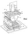
- FIG. 11shows one preferred embodiment of a sample holder that can be used in the automated rapid serial system.
- FIG. 12is a flow schematic diagram of the automated rapid serial system that can be used for high throughput fabric handle screening.
- the present inventioncomprises methods for high throughput screening of a plurality of fabric samples for mechanical properties generally associated with fabric handle, by measuring the responses of individual array samples to protrusions.
- a plurality of fabric samplesis assembled together to define an array of fabric samples.
- the fabric samples materials in the arraycan be the same or different materials.
- the arraycan be supported on a single common support or a plurality of assembled supports. A further detailed description of the array of fabric samples is provided below in the section titled “Preparation of an Array of Fabric Samples”.
- protrusionsgenerally refers to controlled forces or displacements applied by a probe, or device to a fabric sample for causing at least a portion of the fabric sample to be forced through an opening defined in a plane of a sample support member.
- a protrusion as used hereinwill be of sufficient magnitude for effecting such sample manipulation without piercing the sample. In some embodiments, however, it is contemplated that piercing will or desirably should occur.
- the sampleAs the sample is passed through the opening (i.e., pushed out of the normal plane of the opening), it is expected to become folded, sheared, bent, compressed, elongated, or rubbed against the interior wall of the support member defining the opening.
- Responses to the protrusionsare measured and recorded as a load-displacement curve as shown in FIG. 1 .
- the load displacement curveyields the mechanical properties associated with or bearing upon fabric handle such as bending modulus, shear stiffness, compression, friction, and extensibility, or the like.
- the number of fabric samples in an arraymay vary depending on the embodiment being practiced. In some embodiments, an array will comprise four or more, eight or more, sixteen or more, twenty-four or more, or forty-eight or more fabric materials. Those of skill in the art will appreciate from this specification that members of the array may be the same or different materials. Fabric samples may be woven or unwoven, coated or uncoated, or aggregated with a suitable binder or not.
- the present inventionis not limited to any particular type of fabric material and may include a woven material (e.g., batiste, chiffon, net, voile, organza, georgette, challis, chambray, charmeuse, crepe, dotted swiss, handkerchief linen, satin, eyelet, lace, velvet, taffeta, metallic, gauze, jacquard, gingham, percale, seersucker, broadcloth, brocade, linen, pique, shantung, chintz, velveteen, polyester blend acrylic, fleece, gabardine, denim, twill, corduroy, terry, velour, canvas, duck, percale, tergal, flannel, lame, tricotine, etc.), a non-woven material (e.g., felt, fusibles, interfacing, etc.), a knit material (e.g., atlas, jersey, pointelle, raschel, mesh, panne velvet,
- the fabric materialscan be natural (e.g., cotton, silk, linen, wool, hemp, ramie, jute, etc.), synthetic (e.g., acetate, acrylic, lastex, nylon, polyester, rayon, etc.), or combination thereof. They can also be acrylic coated, airo finished, bleached, resin treated, sanded, scented, sheared, silver coated, wax coated, stonewashed, bonded, enzyme washed, flocked, glazed, mercerized, milled/fulled, and subject to other textile treatments for color, texture, bacterial resistant, soil resistant, oil repellent, flame resistant, pill resistant water resistant, mildew resistant, water repellant, wrinkle resistant, or ultra violet resistant, etc.
- naturale.g., cotton, silk, linen, wool, hemp, ramie, jute, etc.
- synthetice.g., acetate, acrylic, lastex, nylon, polyester, rayon, etc.
- Theycan also be acrylic coated, airo finished, bleached,
- Standardssuch as calibration standards
- blanksmay be employed in the array for known scientific purposes.
- the present inventionis particularly attractive for the screening of effects of variations of textile treatments and/or additives (e.g., surfactants, fillers, reinforcements, flame retardants, colorants, environmental protectants, other performance modifiers, control agents, plasticizers, cosolvents, accelerators, etc.) upon the fabric handle of a fabric material.
- additivese.g., surfactants, fillers, reinforcements, flame retardants, colorants, environmental protectants, other performance modifiers, control agents, plasticizers, cosolvents, accelerators, etc.
- Relative comparison of the fabric hand of array membersis a useful embodiment of this invention.
- Quantitative measurements of fabric handare also provided by the present invention. The quantitative measurements allow comparison of fabric hand between the array members and other fabric materials not included in the array.
- different material samplesare compared with each other (quantitatively or qualitative, according to defined criteria) and their relative performance is ranked.
- different material samplesare compared to determine whether a specific response has occurred in any of the material samples. From the analysis of the materials, sub-sets of materials can be identified for further study or for production in bulk-scale quantities, such as for commercial application.
- fibersare aggregated in a generally cohesive manner.
- the materialis aggregated together with a suitable binder, (e.g., by applying in a wet state an emulsion containing waxes or polymers that, when dried, will form a continuous phase around the non-woven fibers).
- a particularly preferred binder for use in the present inventionis an aqueous emulsion including a polymer (more preferably a copolymer).
- a more preferred binderalso may include, a stabilizer, a surfactants, a crosslinking agent, or other suitable agent to impart mechanical strength to the system (e.g., once it has been exposed to elevated temperature ( ⁇ 150° C.)).
- the bindermay add 1 to 99, preferably 5 to 50, more preferably 10-30 percentage weight to the fabric material.
- binder to binderare (1) the monomers used in the polymerization; (2) the order in which they are attached (random or blocky); (3) the surfactants; and (4) any other additives that may give the system unique characteristics (e.g., something that is sensitive to the presence of ions).
- One preferred binderincludes an olefin, a vinyl ester, or a combination thereof, and an example of such a preferred binder is a copolymer of ethylene and vinyl acetate in an emulsion with various stabilizers.
- suitable binderssee U.S. Pat. Nos. 4,605,589, 4,975,320 and 6,043,317.
- the bindershould generally be uniformly distributed throughout the non-woven material, but it also may be randomly distributed. Such uniform distribution can be achieved using any number of conventional techniques. For example, the non-woven material immersed with the binder is passed through spaced opposing surfaces such as rubber-coated rollers with a self-adjusting gap to squeeze out any excess binder and provide uniform distribution. Depending on the nature of the binder (e.g., whether it contains any cross-linkable polymers), a drying step and/or a curing step can be used to process the non-woven material treated with the binder.
- binders employedmay be the same or different.
- each array samplecan generally vary, depending on the particular characterization protocols and systems used to analyze the sample. It is generally contemplated that arrays of samples will be mounted for screening in or on a suitable support structure, namely a sample holder. Typically, the sample holder will have at least one and more preferably a plurality of openings defined therein. Thus, in one preferred embodiment, the sample size will be larger than the opening through which it will be forced by a probe during screening. It is preferred that the sample is at least about 2 times larger than the opening, more preferred at least about 5 times larger than the opening, and most preferred about 10 times larger than the opening. It is appreciated that the present invention advantageously permits for attaining reliable data with relatively small samples, but the actual sample size is not critical. Typical sample sizes can range from about 8 mm to about 18 mm, more preferred from about 12 mm to about 18 mm, and most preferred from about 15 mm to about 17 mm. Larger diameters are also possible.
- FIG. 2shows a perspective view of one instrument suitable for property analysis (i.e., screening), and specifically, a parallel dynamic mechanical analyzer (PDMA) 100 that can be used to conduct high throughput fabric handle screening of an array of fabric samples 230 by measuring responses of the array 230 to protrusions.
- PDMAparallel dynamic mechanical analyzer
- the PDMA 100includes a sample holder 102 for containing the array 230 , probes 104 for protruding the array 230 , and sensors 106 (e.g., force sensors) for measuring the array's 230 responses to the protrusions.
- the sample holdermay be a single integrated unit or a plurality of assembled components; likewise it may comprise a single opening in a first substrate, which is translatable (e.g., by robot arm) relative to a second substrate for holding sample.
- FIG. 3Ashows a cross-sectional view of one preferred sample holder 102 which is comprised of a first plate 402 having a plurality of through-holes 406 and a second plate 404 having a plurality of openings 407 wherein the through-holes 406 and the openings 407 are aligned with each other forming tunnels 410 within the sample holder 102 . Since the array 230 are protruded through the openings 407 , their size and shape can affect the fabric handle measurements and are taken into consideration in measuring the fabric handle of the array 230 .
- each of the openings 407preferably is large enough for the array sample 230 to collapse upon itself, while still maintaining a portion of itself in physical contact with the walls of the opening 407 during the protrusions.
- one preferred leading edge 408 to the opening 407must allow for a smooth transition for the sample 230 to transfer from a flat state to the bent and folded state which occurs during the protrusions.
- the opening 407is constructed of a smooth material or coated with a smooth material (e.g., a plastic layer, a coating, or the like).
- the openings 407can be any shape and/or size, it is preferred that they are funnel-shaped or otherwise a rounded or a tapered periphery with a diameter at the top of each funnel that is twice of the bottom diameter, and with the height of the sloped section at least equal to the height of the straight section.
- the through-holes 406can also be any shape or size as long as they do not restrict or inhibit the protrusions of the array 230 by the probes 104 .
- the first plate 402may be placed above the second plate 404 with its openings 407 as shown in FIG. 3A or vice versa as shown in FIG. 3 B.
- a gap of suitable size 412e.g., preferably about 1 mm, more preferably about 3 mm, exists between the first plate 402 and the second plate 404 .
- the gap 412can be formed by any number of art disclosed techniques.
- spacers 413such as beads or two standard washers (e.g., 0.5 mm each) can be placed between the first plate 402 and the second 404 to create a gap of approximately 1 mm.
- the array 230is placed between the first plate 402 and the second plate 404 of the sample holder 102 with the individual array samples 230 confined to specific locations 414 on the sample holder 102 . Referring to FIG.
- each opening 407is surrounded by an indentation 409 in the second plate 404 that restricts any horizontal movement of its respective sample 230 . It is also preferred that there is a one to one correspondence between the specific locations 414 and the openings 407 . Additionally, it is preferred that the samples 230 do not overlap each other but each sample 230 is sized to include and extend beyond the regions defined by the diameter of the opening 407 . It is preferred that each sample 230 is at least about 2 times larger than the diameter of the opening 407 , more preferred at least about 5 times larger than the diameter of the opening 407 , and most preferred about 10 times larger than the diameter of the opening 407 .
- sample holder 102can be designed to contain any number of samples in an array.
- the sample holder 102can be designed to contain 4 or more, 8 or more, 16 or more, 24 or more or 48 or more samples in an array.
- the PDMA 100generally has as many probes 104 as desired. For example there may be as many as there are samples in the array 230 , although for clarity, FIG. 2 shows only two probes 104 . In the embodiment shown in FIG. 2 , the probes 104 have the same lateral spacing as the tunnels 410 or openings 407 so that one probe 104 is associated with one opening 407 or sample 230 . Alternatively, the PDMA may employ fewer probes 104 than samples in the array 230 , so that a group of probes 104 protrudes multiple samples 230 .
- the PDMA 100includes a translation mechanism capable of three-dimension motion, which is attached to this group of probes 104 or to the sample holder 102 to allow high throughput serial-parallel screening.
- the PDMA 100includes a translation mechanism capable of three-dimensional motion, which is attached to the single probe 104 or to the sample holder 102 to allow high throughput screening in a rapid serial fashion.
- the PDMA 100includes at least one actuator for moving the probes 104 and the samples 230 in relation to each other.
- the actuatorsare attached to the probes 104 and the samples 230 remain stationary.
- the actuatorsare attached to the sample holder 102 and the probes remain stationary.
- both the probes 104 and the sample holder 102have actuators attached allowing them to both become non-stationary.
- the PDMA 100includes first 110 and second 112 translation actuators for displacing the array 230 in a direction normal 114 to surfaces containing the array 230 and the ends 116 of the probes 104 .
- the first translation actuator 110which is attached to the sample holder 102 via a housing 117 that surrounds the second translation actuator 112 , provides relatively coarse displacement of the sample holder 102 .
- a useful first translation actuator 110includes a motorized translation stage available from POLYTEC PI under the trade name M-126 Translation Stage, which has a translation range of 25 mm and a resolution of 0.1 ⁇ m.
- the second translation actuator 112which is attached directly to the sample holder 102 , provides relatively fine displacement of the sample holder 102 .
- a useful second translation actuator 112includes a preloaded piezoelectric stack available from Polytec PI under the trade name P-753 LISA Linear PZT Stage Actuator, which has a translation range of 30 mm and can provide a 100-N pushing force and a 20-N pulling force.
- the PDMA 100typically controls the first 110 and second 112 translation actuators using a DC motor controller and an amplifier/position servo controller, respectively, which are linked to a suitable general-purpose computer (not shown).
- the first 110 translation actuatoris mounted on an x-y translation stage (not shown), which allows movement of the sample holder 102 in a direction substantially parallel to the surfaces containing the array 230 and the ends of the probes 104 .
- This latter embodimentis useful when the sample holder 102 must be moved laterally to align different groups of array samples 230 with the probes 104 during screening—i.e., when the PDMA employs fewer probes 104 than samples in the array 230 and the probes 104 are stationary.
- Each of the probes 104includes a test fixture 118 that contacts one of the sensors 106 through a solid or composite shaft 120 shown in phantom in FIG. 2 .
- Each shaft 120passes through an aperture 122 in an isolation block module 124 that separates the probe test fixture 118 from the sensor 106 .
- FIG. 2shows only two isolation block modules 124 , although this embodiment of the PDMA 100 ordinarily includes twelve such modules 124 —one isolation block module 124 for each row of eight probes 104 .
- the PDMAmay include a single isolation block for separating the probe test fixtures 118 from the sensors 106 .
- each test fixture 118should contact its associated sample 230 in a specific location 108 on the sample holder 102 .
- conventional linear bearingscan be used to align the composite shaft 120 , friction between the linear bearings and the shaft 120 limits the displacement resolution at low force levels.
- the PDMAcan also use air bearings, but the size and expense of air bearings often make them impractical for use with a PDMA employing relatively large numbers of probes 104 .
- FIG. 4which illustrates the use of two flexure strips 150 to align the probes 104 with the samples 230 , shows a cross-sectional view of one of the isolation block modules 124 as seen through a cutting plane containing centerlines of the apertures 122 shown in FIG. 2 .
- the flexure strips 150are sandwiched between generally planar surfaces of upper 152 and intermediate 154 segments of the isolation block module 124 and between generally planar surfaces of the intermediate 154 and lower 156 segments of the isolation module 124 .
- the two flexure strips 150 shown in FIG. 4comprise relatively thin (from about 10 ⁇ m to about 100 ⁇ m) rectangular membranes having spaced-apart holes that are substantially aligned with each composite shaft 120 within the apertures 122 of the isolation block modules 124 .
- the composite shaft 120is comprised of a rigid, substantially cylindrical core 158 and a thermally insulating outer sheathing having upper 160 , intermediate 162 , and lower 164 sections that are threaded onto the core 158 .
- the abutting ends of the upper 160 and intermediate 162 sections of the sheathing and the intermediate 162 and lower 164 sections of the sheathinglie in planes containing the two flexure strips 150 . Since the diameters of the core 158 and the holes in the flexure strips 150 are about the same, the periphery of the holes are clamped between the abutting ends of the upper 160 , intermediate 162 , and lower sections of the sheathing.
- the flexure strips 150are also clamped along the periphery of each aperture 122 , adjacent interfaces between the upper 152 , intermediate 154 , and lower segments 156 of the isolation block module 124 .
- the resulting clamped membranes or diaphragms 166which span annular gaps 168 between the shafts 120 and the isolating block module 124 , support and align the probes 104 .
- the geometry of the diaphragms 166makes each of the flexure strips 150 compliant for displacements normal 114 to the surface supporting or containing the array 230 , but mechanically stiff for displacements parallel to the array 230 .
- the use of two flexure strips 150also makes each combination of shaft 120 and diaphragms 166 mechanically stiff for angular displacements away from the direction normal 114 to the surface of the array 230 .
- the flexure strips 150exhibit effective spring constants—for displacements normal 114 to the array 230 —substantially less than effective constants of the sensors 106 .
- the flexure strips 150ordinarily exert minimal influence on the measured responses to protrusions, unless they are used to “pre-load” the sensors 106 as discussed below.
- Useful materials for the flexure strips 150include metallic and polymeric films.
- one particularly useful flexure strip materialis polyimide film, which is available from DuPont under the trade name KAPTON in thickness ranging from about from about thirteen ⁇ m to about one hundred twenty five ⁇ m.
- Other useful flexure materialsinclude stainless steel foil, diaphrams (in general) and corrugated bronze, for example, the flexure may be mechanically machined stainless steel.
- thermally insulating sheathing 160 , 162 , 164 on the shafts 120permits the PDMA 100 to vary the temperature of the arrays 230 without significantly affecting the measured response.
- the PDMA 100employs a probe 104 having a blunt end (not shown) for protruding the array 230 .
- the probe 104can be equipped with a blunt end test fixture 118 for protruding the array 230 .
- the PDMA 100may provide a mechanism for removing and securely attaching the test fixtures 118 . Suitable attachment mechanisms include mechanical and electromagnetic couplings, as well as devices employing permanent magnets.
- FIG. 5shows a close-up cross sectional view of the probe 104 shown in FIG. 4 , and illustrates the use of a permanent magnet 190 to attach the test fixture 118 to the threaded core 158 of the composite shaft 120 . As shown in FIG.
- the probe 104includes a base 192 having first 194 and second ends 196 that adjoin, respectively, the test fixture 118 and the upper section 160 of the thermally insulating outer sheathing.
- a substantially cylindrical bore 198extends partway into the base 192 and is sized and threaded to connect the core 158 of the shaft 120 to the second end 196 of the base 192 .
- the test fixture 118is removably attached to the first end 194 of the base 192 by magnetic flux originating from the permanent magnet 190 that is embedded in the base 192 of the probe 104 .
- a tubular magnetic shield 200which typically has a lower modulus than either the probe base 192 or the permanent magnet 190 , is wedged into an annular space between the probe base 192 and the permanent magnet 190 .
- the shield 200which helps secure the magnet 190 within the probe base 192 , extends outward from the first end 194 of the base 192 and mates with a substantially circular slot 202 formed in the test fixture 104 .
- the slot 202is sized to receive the tubular shield 200 with minimal interference, and the shield 200 has a tapered end 204 that helps guide it into the slot 202 during attachment of the test fixture 118 to the probe base 192 .
- the test fixture 118 and the test fixture 118 and the probe base 192include flanges 206 , 208 for accessing them during removal or attachment.
- the test fixture 118 , the base 192 , and the shield 200enclose the permanent magnet 190 , which helps minimize stray magnetic flux that may influence sample measurements of nearby probes 104 .
- the probe 104 componentsare made from materials having a high magnetic permeability—a relative permeability substantially greater than unity—to ensure effective magnetic shielding. Suitable materials include nickel-iron alloys containing copper, molybdenum, or chromium and mixtures thereof. A particularly useful shielding material is available under the trade name HI-PERM 49 from Carpenter Technology. Other useful shielding materials include cold-rolled steel that has been chrome-plated to resist corrosion.
- the permanent magnet 190should be fabricated from a material that provides sufficient force to secure the test fixture 118 to the probe base 192 during screening.
- Useful permanent magnets 190include samarium cobalt magnets, ceramic ferrite magnets, aluminum-nickel-cobalt magnets, and neodymium-iron-boron magnets.
- FIG. 6illustrates interactions of the probes 104 , the sensors 106 , and the array of fabric samples 230 .
- FIG. 6shows a cross sectional view of the PDMA 100 of FIG. 2 taken from a plane that cuts through the two isolation block modules 124 and contains centerlines of two adjacent probes 104 .
- each test fixture 118 portion of the probes 104interacts with an individual array sample 230 , which is positioned at a specific location 414 of the sample holder 102 over an opening 407 . Movement of the sample holder 102 in a direction normal 114 to the surface of the array 230 results in forces that are transmitted to the sensors 106 via each probe test fixture 118 , probe base 192 , and composite shaft 120 .
- Each composite shaft 120which includes a rigid core 158 and thermally insulating outer sheathing 160 , 162 , 164 , contacts the force sensor 106 directly or indirectly as discussed below.
- each sensor 106 shown in FIG. 6makes it impracticable to mount all of the sensors 106 on a single plane while maintaining 9 mm spacing between centers 126 of adjacent sensors 106 .
- the PDMA 100employs sensors 106 mounted on first 232 and second 234 sensor boards, which rest on upper 236 and lower 238 rigid support plates, respectively.
- Both support plates 236 , 238include holes that extend from top surfaces 240 , 242 of the plates 236 , 238 to bottom surfaces 244 , 246 of the plates 236 , 238 .
- the holesare arrayed on 9 mm centers, and are either threaded or non-threaded.
- Non-threaded holes 248 in the upper support plate 236are substantially aligned with through-holes 250 in the first sensor board 232 .
- the non-threaded holes 248 and the through-holes 250are sized to provide passageways for rods 252 that transmit forces from the composite shafts 120 to sensors 106 mounted on the second (lower) sensor board 234 .
- the PDMA 100thus maintains the most preferred spacing by distributing the force sensors 106 among two boards 232 , 234 —thereby doubling the surface area available to mount the force sensors 106 —and by arranging the sensors 106 so their centers 126 are 9 mm apart when projected on the surface of the array 230 .
- the PDMAmay dispense with one of the two sensor boards. As many sensor boards as is practical for a particular embodiment may be employed.
- FIG. 7 and FIG. 8provide further details of the sensors 106 and sensor boards 232 , 234 , showing respectively, a bottom perspective view and a close-up top view of the first sensor board 232 .
- the first 232 and second 234 sensor boardsgenerally comprise a flexible multi-layer dielectric sheet 270 (e.g., polyimide) and a rigid frame 272 (e.g., FR-4 epoxy glass laminate) that is bonded to the periphery of the dielectric sheet 270 .
- Electrically conductive traces 274are embedded on top 276 or bottom surfaces of the dielectric sheet 270 , or between layers of the flexible sheet 270 , forming a double-sided flex circuit 280 .
- Each sensor 106is mounted on the top surface 276 of the flex circuit 280 , and leads 282 on the sensors 106 are connected to conductive traces 274 that terminate at a standard card edge connector 284 .
- Conventional ribbon cablescan be used to link the card-edge connector 284 with peripheral recording and control devices (not shown) allowing communication between the sensors 106 and the peripheral devices.
- the first 232 and second 234 sensor boardsinclude generally planar stiffeners 286 (e.g., FR-4 epoxy glass laminates) attached to the bottom surface 278 of the sensor boards 232 , 234 directly below the sensors 106 .
- Each of the stiffeners 286has about the same footprint as the sensors 106 , and helps distribute loads on, and prevent bending of, the sensors 106 . Note however, the stiffeners 286 do not prevent movement of the sensors 106 in a direction normal 114 to the array 230 since the sensors 106 are mounted on the flexible dielectric sheet 270 .
- Pre-loadinguses sensors 106 mounted on the flex circuit 280 to allow “pre-loading” of the sensors 106 as discussed below. Pre-loading may of course be performed by other methods, which those of skill in the art will appreciate from a review of this specification. Furthermore, a detailed discussion of “pre-loading” is set forth in the commonly owned and co-pending U.S. patent application Ser. No. 09/580,024 titled “Instrument for High Throughput Measurement of Material Physical Properties and Method of Using Same,” filed on May 26, 2000, which has been incorporated by reference.
- the first sensor board 232 shown in FIG. 8also includes a plurality of through-holes 250 that are located between the sensors 106 .
- the through-holes 250are substantially aligned with unthreaded holes 248 in the upper support plate 236 (FIG. 6 ).
- the unthreaded holes 248 in the upper support plate 236provide passageways for rods 252 that transmit forces from the composite shafts 120 to sensors 106 mounted on the second (lower) sensor board 234 .
- the centers 126 of the sensors 106 and the through-holes 250 of the first sensor board 232are arrayed on 9 mm centers.
- threaded holes 248 , 290 in the upper 236 and lower 238 support platesare sized to receive set-screws 292 that the PDMA 100 can use to pre-load each of the sensors 106 mounted on either the first 232 or second 234 sensor boards.
- the flexure strips 150 used to align the probes 104are compliant for displacements normal 114 to the plane containing the array 230 , but are mechanically stiff for displacements in other directions.
- the effective spring constants of the flexure strips 150are substantially less than the spring constants of the sensors 106 so that the flexure strips 150 ordinarily exert minimal influence on the measured responses of the array 230 to protrusions.
- the set-screws 292can apply a force to the stiffeners 286 and the sensors 106 in absence of a force on the test fixture 118 .
- a force recorded by the sensors 106will therefore be the sum of the force acting on the test fixture 118 and the pre-load force. Since many commercial force sensors can detect only tensile or compressive loads, pre-loading permits a compressive sensor to detect small tensile loads, or a tensile sensor to record small compressive loads, expanding the capabilities of the PDMA 100 .
- the lower support plate 238 and the second sensor board 234both include unthreaded holes 294 , 296 that provide access to the set-screws 292 in the upper support plate 236 .
- the PDMA 100can use a wide variety of sensors 106 , including miniature force sensors. Most of the sensors 106 incorporate signal conditioning electronics. Suitable force sensors include piezoresistive micromachined silicon strain gauges that form a leg of a conventional Wheatstone bridge circuit. A useful low-compliant force sensor is available from Honeywell under the trade name FSL05N2C. The Honeywell force sensor has a 500-g range (4.9 N full scale), which is suitable for most of the screening methods described in subsequent sections. As noted earlier, many force sensors can tolerate only modest variation in temperature without compromising accuracy and precision. The use of a composite shaft 120 having an insulating sheathing 160 , 162 , 164 ( FIG. 4 ) permits substantial temperature variation of the array 230 without significantly affecting the temperature and accuracy of the sensors 106 .
- force sensorsare incorporated into the flexure strips 150 by placing strain gages on the diaphragms 166 (FIG. 4 ). Strain resulting from the application of a known force—typically a deadweight load applied to the rigid shaft 120 —is recorded and used to develop a calibration curve for the force sensor.
- a known forcetypically a deadweight load applied to the rigid shaft 120
- the principal disadvantage of this approachis the extensive signal conditioning requirements associated with strain gage measurements.
- the PDMA 100may include an environmental chamber (not shown) that encloses the sample holder 102 , the probes 104 , and the upper 152 or intermediate 154 segments of the isolation block modules 124 that control the environment (e.g., temperature, humidity, etc.) of the samples 230 .
- the chambermay be filled with a gas of known composition to study its influence on the fabric handle of the samples 230 .
- the annular gap 168 between the composite shafts 120 and the cylindrical apertures 122is minimized to limit the flow of gas out of the isolation block modules 124 .
- the flexures 150 in the annular gaps 168restrict gas efflux from the isolation block modules 124 .
- the environmental chambermay comprise a substantially gas-tight enclosure that surrounds the sample holder 102 , the probes 104 , the isolation block modules 124 , and the sensors 106 .
- the enclosuremay be further separated into two compartments—one that encloses the sample holder 102 and the samples 230 , and one that encloses the sensors 106 and the isolation block modules 124 .
- the latter embodimentallows blanketing the sample holder 102 and the samples 230 with a first gas that is different than a second gas blanketing the sensors 106 .
- the PDMAcan vary the environment of the samples 230 independently of the sensors 106 , while maintaining the sensors 106 at conditions different than or the same as the laboratory environment.
- the environmental chambermay include devices for regulating and/or monitoring the temperature of the samples 230 .
- Useful devicesinclude one or more heating or cooling elements placed within a gas stream that feeds the environmental chamber containing the array 230 .
- Other useful devicesinclude an array of radiant heaters positioned adjacent to the samples 230 .
- the PDMA 100may include resistance heaters or thermoelectric devices that are attached to the sample holder 102 , which heat or cool individual or groups of samples in the array 230 .
- the PDMA 100may also include devices such as thermocouples, thermistors, or resistive thermal devices (RTD) for monitoring the temperature of individual samples 230 .
- RTDresistive thermal devices
- the PDMA 100includes a temperature controller, such as a data acquisition board, for subjecting the array 230 to a desired temperature-time profile.
- the temperature controllerautomatically adjusts the power supplied to the heating and cooling devices in response to signals received from the temperature monitoring devices.
- software running on an external computercommunicates and coordinates functions of the temperature controller and the temperature monitoring devices.
- FIG. 9shows schematically a system 300 for data acquisition and control of the PDMA.
- the PDMA 100includes first 110 and second 112 translation actuators for displacing the array 230 ( FIG. 6 ) in a direction normal 114 to the probes 104 .
- the first translation actuator 110provides relatively coarse displacement of the sample holder 102 ; it positions the samples 230 near the probe 104 test fixtures 118 , and can be regulated using a DC motor controller (not shown).
- the second translation actuator 112provides relatively fine displacement of the sample holder 102 and is responsible for carrying out protrusions of the individual samples 230 .
- the second translation actuator 112 shown in FIG. 9comprises a piezoelectric translation stage.
- a primary data acquisition board 302e.g., National Instruments 6030E
- the primary board 302controls the operation of the second translation actuator 112 .
- the primary board 302generates a voltage, V 1 , which is proportional to the desired displacement of the actuator 112 (and sample holder 102 ).
- V 1is fed to a piezoelectric amplifier 306 that monitors the position of the actuator 112 via a capacitive position sensor 308 .
- V 1the piezoelectric amplifier 306 varies the charge, V 2 , which it supplies to the actuator 112 to move the sample holder 102 to its desired position.
- the position sensor 308generates a voltage, V 3 , which is read by the amplifier 306 and indicates the actual position of the second translation actuator 112 .
- the primary data acquisition board 302 and the external computer 304respectively, read and record V 3 .
- the primary board 302updates V 1 as necessary and generates a timing pulse, which triggers acquisition of V 3 from the position sensor 308 , thereby synchronizing signals V 1 and V 3 .
- the acquisition of V 3also generates a second timing pulse, V 4 , which triggers acquisition of voltages V 5,i , V 6,i , and V 7,i , from the sensors 106 .
- Secondary data acquisition boards 310acquire V 5,i , V 6,i , and V 7,i , where subscript refers to a particular data line (channel) of the data acquisition board 310 .
- measurements of the response of the array 230 to protrusionsare synchronized with the motion of the second translation actuator 112 (and sample holder 102 ), and the measurement of the actuator 112 position.
- the system 300 shown in FIG. 8uses three secondary data acquisition boards 310 having 32 channels each, the number of boards 310 will depend on the number of available data channels and sensors 106 .
- the PDMAmay use a single data acquisition board to control the actuator 112 position and to acquire sensor 106 data, assuming the board has a sufficient number of data channels and output signals.
- Software running on the computer 304coordinates the activities of the boards 302 , 310 and allows the user to specify screen parameters including positions of the first 110 and second 112 translation actuators at any given time, the number of samples 230 , and so on.
- the methodology for high throughput fabric handle screening used in this experimentgenerally includes the following steps: (1) providing a plurality of samples of non-woven materials; (2) aggregating the materials in a binder; (3) placing the samples on a sample holder having a plurality of openings with smooth edges; (4) protruding the samples; (5) measuring the response of each sample; (6) comparing the samples relating to each other; (7) identifying the samples that meet predetermined criteria and/or ranking the samples based upon their individual performance; and (8) preparing bulk scale quantities of a material or materials based upon the results of this high throughput fabric handle screening.
- the method of screening fabric handle using the PDMA 100begins with placing the array of fabric samples 230 between the first plate 402 and the second plate 404 of the sample holder 102 with the individual samples 230 confined to specific locations 414 on the sample holder 102 . Thereafter, the samples 230 in the sample holder 102 are translated in a direction normal to the ends 116 of the probes 104 . Alternatively, as discussed above, the translation can be achieved by the probes 104 in a direction normal to the sample holder 102 or both by the probes 104 and the sample holder 102 in a direction normal to both. The translation is preferred to be conducted at a constant speed controlled by the system 300 .
- the speedis less than 10 mm per second but greater than about 1 mm, but more preferably about 5 mm per second.
- the samples 230continue to translate in the direction normal to the ends 116 of the probes 104 , they first contact the blunt ends of the probes 104 through the through-holes 406 of the first plate 402 and then begin to fold and are eventually, and preferably completely, forced through the openings 407 of the second plate 404 .
- the translation from the point of first contact between the blunt ends of the probes 104 and the samples 230should be a distance at least equal to, and preferably greater than, the radius of the samples 230 .
- each sample 230is preferably first contacted by the probe 104 at its center point and then becomes folded, sheared, bent, compressed, elongated, and rubbed against the interior wall of the opening 407 .
- the force sensorsregister all the forces transmitted through the probe 104 and the information is transferred to the system 300 .
- the outputis a trace of force versus position of the sample holder 102 providing a load-displacement curve as shown in FIG. 1
- the probes 104have about the same lateral spacing as the tunnels 410 and/or the openings 407 so that there is a one-to-one correspondence between the individual probes 104 and the samples in the array 230 .
- the systemcan protrude all of the array samples 230 simultaneously by displacing the array 230 (sample holder 102 ) and/or the probes 104 in a direction normal to the two surfaces. If adapted to protrude all of the array samples 230 simultaneously, the system may include a rectilinear translation stage that is attached to the sample holder 102 or the probes 104 .
- the systemmay protrude individual or groups of array samples 230 in a rapid serial fashion.
- the systemmay include a translation mechanism capable of three-dimensional motion, which is attached to a single probe 104 , to a group of probes 104 , or to the sample holder 102 .
- FIG. 10shows a perspective view of another instrument suitable for screening, and specifically, an automated rapid serial system (ARSS) 500 that can be used to conduct high throughput fabric handle screening of an array of fabric samples by measuring responses of the array samples to protrusions.
- the ARSS 500can be configured for use with parallel, serial or serial-parallel protocols.
- the ARSS 500can be configured for use in a rapid serial fashion with a high sample screening throughput.
- Detailed description of the ARSS 500is described in commonly owned and co-pending U.S. patent application Ser. No. 09/939,252 titled “High Throughput Mechanical Rapid Serial Property Testing of Material Libraries,” (P. Mansky) filed on Aug. 24, 2001, which is herein incorporated by reference.
- ARSS 500includes a variety of robotic instruments for automatically or programmably providing predetermined motions for protruding an array of fabric samples 502 according to a predetermined protocol.
- ARSS 500may be adapted or augmented to include a variety of hardware, software or both to assist it in determining the fabric hand of the array members.
- Hardware and software for augmenting the robotic systemsmay include, but are not limited to, sensors, transducers, data acquisition and manipulation hardware, data acquisition and manipulation software and the like.
- Exemplary robotic systemsare commercially available from CAVRO Scientific Instruments (e.g., Model NO. RSP9652 or BioDot Microdrop Model 3000).
- the ARSS 500includes a sample holder 504 having a plurality of openings 506 .
- the array of fabric samples 502is preferably confined to specific locations 508 located on the sample holder 504 with one to one correspondence between the specific locations 508 and the openings 506 , and that the array samples 502 do not overlap each other but include and extend beyond the regions defined by the diameter of the openings 506 .
- each opening 506is surrounded by an indentation 507 in the sample holder 504 that restricts any horizontal movement of its respective sample 502 . This indentation is similar to the indentation in the second plate 404 shown in FIG. 3C for the PDMA 100 instrument.
- each sample 502is at least about 2 times larger than the diameter of the opening 506 , more preferred at least about 5 times larger than the diameter of the opening 506 , and most preferred about 10 times larger than the diameter of the opening 506 .
- the particular sample holder 504 shown in FIG. 10 and FIG. 11contains a 4-by-6 rectangular array of fabric samples 502 located on 18 mm centers.
- the sample holder 504can be designed to contain any number of samples in an array.
- the sample holder 504can be designed to contain 4 or more, 8 or more, 16 or more, or 48 or more samples in an array.
- the size and shape of the openings 506can affect the fabric handle measurements and are taken into consideration in measuring the fabric handle of the array samples 502 .
- the opening 506need to be large enough for the sample 502 to collapse upon itself naturally but still has a portion of itself in physical contact with the walls of the opening 506 during the protrusions.
- one preferred leading edge 510 to the opening 506allows for a smooth transition for the sample 502 to transfer from a flat state to the bent and folded state which occurs during the protrusions.
- the opening 506is constructed out of a smooth material or coated with a smooth material (e.g., a plastic layer, a coating, or the like).
- the openings 506can be any shape and/or size, it is preferred that they 506 are funnel-shaped or otherwise a rounded or a tapered periphery with a diameter at the top of each funnel that is twice of the bottom diameter, and with the height of the sloped section at least equal to the height of the straight section.
- the alternative embodiments of openings shown in FIGS. 3C-Jare also applicable for the ARSS 500 .
- the sample holder 504can have the same specifications as the sample holder 102 described above for the PDMA 100 .
- the ARSS 500also includes a probe 512 (or other similarly functioned device) having a blunt end for protruding the array 502 .
- the probe 512can be equipped with a blunt end test fixture 118 for protruding the array 502 .
- the ARSS 500can generally include as many probes 512 as desired, for example there may be as many as probes 512 as there are samples in the array 502 and in a preferred embodiment, the probes 512 have about the same lateral spacing as the openings 506 so that one probe 512 is associated with one opening 506 or sample 502 .
- the ARSSmay employ fewer probes 512 than samples in the array 502 , so that a group of probes 512 protrudes multiple samples 502 , or there may be more probes 512 than samples in the array 502 .
- the ARSS 500includes actuator(s) for moving the probe(s) 512 and the samples 502 in relation to each other.
- the actuatoris attached to the probe 512 and the samples 502 remain stationary.
- the actuatoris attached to the sample holder 504 and the probe 512 remains stationary.
- both the probe 512 and the sample holder 504have actuators attached allowing both of them to translate.
- the ARSS 500includes a suitable protocol design and execution software 516 that can be programmed with information such as location information or other information related to the samples 502 positioned with respect to a sample holder 504 .
- the protocol design and execution software 516is typically in communication with robot control software 518 for controlling a robot 520 or other automated system.
- the protocol design and execution software 516is also in communication with data acquisition hardware/software 522 for collecting data from response measuring hardware 524 .
- the robot control software 518commands the robot 520 having the probe 512 to protrude the samples 502 through the openings 506 .
- the response measuring hardware 524monitors the responses of the samples 502 to the protrusions and provides data on the responses to the data acquisition hardware/software 522 .
- the robot control software 518 , the data acquisition hardware/software 522 or bothtransmit data to the protocol design and execution software 516 such that information about the samples 502 may be matched with the samples' 502 responses to the protrusions and transmitted at data to a database 526 .
- analytical software 528may be used to analyze the data, and more specifically, to determine the mechanical properties associated with the fabric hand of the samples 502 or the data may be analyzed manually.
- the ARSS 500is employed in association with suitable software for combinatorial materials research, such as LIBRARY STUDIOTM, by Symyx Technologies, Inc. (Santa Clara, Calif.); IMPRESSIONISTTM, by Symyx Technologies, Inc. (Santa Clara, Calif.); EPOCHTM, by Symyx Technologies, Inc. (Santa Clara, Calif.); POLYVIEWTM, by Symyx Technologies, Inc. (Santa Clara, Calif.) or a combination thereof.
- suitable software for combinatorial materials researchsuch as LIBRARY STUDIOTM, by Symyx Technologies, Inc. (Santa Clara, Calif.); IMPRESSIONISTTM, by Symyx Technologies, Inc. (Santa Clara, Calif.); EPOCHTM, by Symyx Technologies, Inc. (Santa Clara, Calif.); POLYVIEWTM, by Symyx Technologies, Inc. (Santa Clara, Calif.) or a combination thereof.
- the skilled artisanwill appreciate that the above-listed
- the softwarepreferably provides graphical user interfaces to permit users to design arrays of fabric samples by permitting the input of data concerning the precise location on the sample holder 506 of each sample in the array (i.e., the address of each sample). Upon entry, the software will execute commands to control movement of the robot, for controlling activity at such individual address. Data obtained from the analysis can be compiled and analyzed.
- the ARSS 500further includes an environmental chamber for controlling the environment (e.g., temperature, humidity, etc.) of the array.
- an environmental chamberfor controlling the environment (e.g., temperature, humidity, etc.) of the array.
- An example of a suitable environmental chamberis a thermal jacket for heating and cooling the array 502 as desired (e.g., preferably between ⁇ 100° C. and 200° C.).
- One preferred thermal jacketincludes passages for receiving a heated or cooled fluid such as liquid nitrogen, water, steam or other suitable fluid from a fluid supply. The fluid from the fluid supply may be pumped to the thermal jacket with a pump that is controlled by a controller.
- the method of screening fabric handle using the ARSS 500begins with placing the array of fabric samples 502 in specific locations 508 on the sample holder 504 . Thereafter, the robot 520 , preferably controlled by the robot control software 518 , translates the probe 512 into contact with each sample in the array 502 . Alternatively, as discussed above, the translation can be achieved by the sample holder 504 or by both the probe 512 and the sample holder 504 . The translation is preferred to be conducted at a constant speed controlled by the ARSS 500 . It is also preferred that the speed is less than 10 mm per second but greater than about 1 mm, but more preferably about 5 mm per second.
- each sample 502is preferably first contacted by the probe 512 at its center point and then becomes folded, sheared, bent, compressed, elongated, and rubbed against the interior wall of the opening 506 .
- the response measuring hardware 524register all the forces transmitted through the probe 512 and the information is transfer to the data acquisition hardware/software 522 . Thereafter, the robot control software 518 , the data acquisition hardware/software 522 or both transmit data to the protocol design and execution software 516 such that information about each sample in the array 502 may be matched with its responses to the protrusions and transmitted at data to a database 526 .
- analytical software 528may be used to analyze the data, and more specifically, to determine the mechanical properties associated with the fabric hand of each sample in the array 502 or the data may be analyzed manually.
- the outputis a load-displacement curve as shown in FIG. 1 .
- the load-displacement curve obtained during the high throughput fabric handle screening methods discussed abovecontains information about various mechanical properties associated with fabric handle such as bending modulus, shear stiffness, compression, friction, and extensibility. Due to the extreme complexities of the interactions of these mechanical properties throughout the duration of the screen, extraction of the various properties from the curve is extremely difficult. See Pan, Ning and Yen, K. C., “Physical Interpretations of Curves Obtained Through the Fabric Extraction Process for Handle Measurement,” Textile Res. J. 65(5), 279-290 (1992). The maximum force reached during the protrusion is thus taken to be representative of the overall fabric handle, incorporating all of the various mechanical properties into one value.
- the instruments described above in accordance with the present inventioncan analyze an array having 2 or more samples, and preferably, at least 8 samples to ensure adequate screening throughput.
- Those of skill in the artwill appreciate that lower or higher throughput may serve the needs of a particular application of this invention.
- 4 or more, 8 or more, 16 or more, 24 or more, or 48 or more probes in parallelare within the scope of this invention. These probes may all be in the same test fixture or in multiple test fixtures.
- up to 96 array samplesmay have their mechanical properties associated with fabric handle measured simultaneously in about 10 minutes or less, preferably about 5 minutes or less and even more preferably in about 1 minute or less. In some parallel embodiments, screening throughput of even about 30 seconds or less may be accomplished for an array of the sizes discussed herein, e.g., up to 96 samples in the array.
- fabric handle of each sample in the arrayis detected at an average sample throughput of not more than about 2 minute per sample.
- average sample throughputrefers to the sample-number normalized total (cumulative) period of time required to detect the fabric handle of two or more fabric samples within an array. The total cumulative time period is delineated from the initiation of the screening process for the first fabric sample, to the detection of the fabric handle of the last fabric sample and includes any intervening between-sample pauses in the process.
- the sample throughputis preferably not more than about 30 seconds per sample, more preferably not more than about 20 seconds per sample, even more preferably not more than about 15 seconds per sample, and most preferably not more than about 10 seconds per sample.
- the PDMA 100 and the ARSS 500can be configured to protrude the array samples by clamping, suctioning or pinching a portion (preferably the center portion) of each sample and pulling the sample through the opening. Accordingly, the methods and instruments discussed above are to be considered exemplary and nonlimiting as to the scope of the invention.
- An example of the present inventionis performed upon an airlaid non-woven fabric materials.
- the experimentbegins with cutting an airlaid non-woven fabric material into a rectangle approximately 2′′ ⁇ 1′′ in size and sandwiching between two pieces of polyester scrim to hold the fabric material together during the padding process.
- the fabric materialis placed into a shallow container and soaked with 300 ml of binder solution (generally an emulsion).
- binder solutiongenerally an emulsion
- the binder solutionis diluted down sufficiently so that the percent weight added on to the non-woven fabric material during this process is about 15%.
- the wet fabric materialis passed between two rubber-coated rollers with a self-adjusting gap to squeeze out the excess liquid and ensure a uniform distribution of polymer solids throughout the fibers.
- the sampleis dried at 110° C.
- the fabric materialis cut to form 4 fabric samples with each sample being a 2 cm diameter circle. This process of preparing the fabric samples is repeated 6 times, each time with a different binder to yield an array of 24 fabric samples.
- the fabric samplesare then arranged in a 4 ⁇ 6 array and centered over the funnel-shaped openings in the sample holder. For the 4 ⁇ 6 array, the outer lip of each of the funnel-shaped openings is 12 mm in diameter, and the inner opening is 6 mm in diameter. The centers of the openings are spaced 18 mm apart.
- the arrayAfter the array is placed onto the sample holder, they are then placed onto a cantilever-type load cell with a maximum allowable force of 50N.
- the robotics-control softwareuses the robotics-control software to identify the center of the first opening and the center of the last opening are identified.
- the fabric hand screeningis run using Symyx' ImpressionistTM and EpochTM software.
- the probeis translated to a position slightly above the sample centered on the opening, and moved the probe downwards at a relatively slow speed ( ⁇ 5-10 mm/sec), and collects the response of the load cell as force is applied to the sample. This is repeated for each sample on the array.
- a suitable fitting routinegoes back and fits each peak in the voltage versus time output, identifying such values as peak height and peak width. These parameters are saved to a database, from where they can be later retrieved along with the actual load-displacement curves.
- the screening processtakes approximately 5 seconds per sample allowing the entire array of 24 samples to be screened in less than 2 minutes.
- the peak height of each of the load-displacement curvesis used to rank the fabric hand of the 6 different binders.
- the ranking of fabric hand using the above-described rapid serial techniqueyielded results matching human panel fabric handle screens as shown in Table 1.
- the fabric materialsare correlated from soft to stiff with increasing peak height.
- panelistsare asked to rank the fabric samples in the array from 1 to 6 for softest to stiffest.
- the total points a sample receivedis divided by the number of panelists to obtain the ranking.
- half of the participantsrank the array samples in the same order as the rapid serial test and the other half have two array samples switched.
Landscapes
- Physics & Mathematics (AREA)
- Health & Medical Sciences (AREA)
- Life Sciences & Earth Sciences (AREA)
- Chemical & Material Sciences (AREA)
- Analytical Chemistry (AREA)
- Biochemistry (AREA)
- General Health & Medical Sciences (AREA)
- General Physics & Mathematics (AREA)
- Immunology (AREA)
- Pathology (AREA)
- Engineering & Computer Science (AREA)
- Automation & Control Theory (AREA)
- Treatment Of Fiber Materials (AREA)
- Sampling And Sample Adjustment (AREA)
Abstract
Description
| TABLE 1 | |||||
| Sample | Peak | Force applied | Ranking by | ||
| Identification | height | to sample | Human Panel | ||
| A | 0.0552 | 1.71 N | 1 | ||
| B | 0.0761 | 2.36 N | 2 | ||
| C | 0.0786 | 2.43 N | 3.5 | ||
| D | 0.1059 | 3.28 N | 3.5 | ||
| E | 0.2604 | 8.06 N | 5 | ||
| F | 0.2631 | 8.15 | 6 | ||
Claims (47)
Priority Applications (4)
| Application Number | Priority Date | Filing Date | Title |
|---|---|---|---|
| US09/939,139US6860148B2 (en) | 2001-08-24 | 2001-08-24 | High throughput fabric handle screening |
| US10/225,793US6736017B2 (en) | 2001-08-24 | 2002-08-22 | High throughput mechanical rapid serial property testing of materials libraries |
| PCT/US2002/026888WO2003019157A1 (en) | 2001-08-24 | 2002-08-23 | High throughput mechanical rapid serial property testing of materials libraries |
| AU2002331701AAU2002331701A1 (en) | 2001-08-24 | 2002-08-23 | High throughput mechanical rapid serial property testing of materials libraries |
Applications Claiming Priority (1)
| Application Number | Priority Date | Filing Date | Title |
|---|---|---|---|
| US09/939,139US6860148B2 (en) | 2001-08-24 | 2001-08-24 | High throughput fabric handle screening |
Related Child Applications (2)
| Application Number | Title | Priority Date | Filing Date |
|---|---|---|---|
| US09/939,252Continuation-In-PartUS6837115B2 (en) | 2001-08-24 | 2001-08-24 | High throughput mechanical rapid serial property testing of materials libraries |
| US10/225,793Continuation-In-PartUS6736017B2 (en) | 2001-08-24 | 2002-08-22 | High throughput mechanical rapid serial property testing of materials libraries |
Publications (2)
| Publication Number | Publication Date |
|---|---|
| US20030041663A1 US20030041663A1 (en) | 2003-03-06 |
| US6860148B2true US6860148B2 (en) | 2005-03-01 |
Family
ID=25472600
Family Applications (1)
| Application Number | Title | Priority Date | Filing Date |
|---|---|---|---|
| US09/939,139Expired - Fee RelatedUS6860148B2 (en) | 2001-08-24 | 2001-08-24 | High throughput fabric handle screening |
Country Status (1)
| Country | Link |
|---|---|
| US (1) | US6860148B2 (en) |
Cited By (8)
| Publication number | Priority date | Publication date | Assignee | Title |
|---|---|---|---|---|
| US20040089044A1 (en)* | 2000-11-17 | 2004-05-13 | Fabrice Tondo | Device and method for calibrating a multiple-roller flattener |
| US20040146433A1 (en)* | 2003-01-29 | 2004-07-29 | Peter Massaro | Sample handling tool with piezoelectric actuator |
| US20050229709A1 (en)* | 2004-04-15 | 2005-10-20 | Lopushansky Richard L | Flame shield for high temperature pressure transducer |
| US20100069257A1 (en)* | 2008-09-15 | 2010-03-18 | Dow Global Technologies Inc. | Porous sample testing device and methods |
| US20110296901A1 (en)* | 2010-06-02 | 2011-12-08 | Jim Quentin Nichols | Hydrostatic tester |
| WO2012104627A2 (en) | 2011-01-31 | 2012-08-09 | University Of Leeds | Evaluation apparatus and method |
| US10307795B2 (en)* | 2016-05-04 | 2019-06-04 | Fabscrap, Inc. | Scalable systems and methods for classifying textile samples |
| US10613020B2 (en)* | 2017-08-10 | 2020-04-07 | The Boeing Company | Burr detection systems and methods |
Families Citing this family (12)
| Publication number | Priority date | Publication date | Assignee | Title |
|---|---|---|---|---|
| US6664067B1 (en) | 2000-05-26 | 2003-12-16 | Symyx Technologies, Inc. | Instrument for high throughput measurement of material physical properties and method of using same |
| US20040123650A1 (en)* | 2002-09-17 | 2004-07-01 | Symyx Technologies, Inc. | High throughput rheological testing of materials |
| US7514041B2 (en)* | 2004-07-28 | 2009-04-07 | N-Solv Corporation | Method and apparatus for testing heavy oil production processes |
| US8000837B2 (en) | 2004-10-05 | 2011-08-16 | J&L Group International, Llc | Programmable load forming system, components thereof, and methods of use |
| GB0518423D0 (en)* | 2005-09-09 | 2005-10-19 | Ici Plc | Materials testing |
| CA2549614C (en)* | 2006-06-07 | 2014-11-25 | N-Solv Corporation | Methods and apparatuses for sagd hydrocarbon production |
| CA2552482C (en)* | 2006-07-19 | 2015-02-24 | N-Solv Corporation | Methods and apparatuses for enhanced in situ hydrocarbon production |
| CN101178397B (en)* | 2007-12-03 | 2011-06-01 | 苏州工业园区慧博自动化技术有限公司 | Fabrics hand-feel emulation system tester |
| WO2013016604A1 (en)* | 2011-07-28 | 2013-01-31 | The Procter & Gamble Company | Method for assessing condition of fibers |
| DE102018217225A1 (en)* | 2018-10-09 | 2020-04-09 | Fraunhofer-Gesellschaft zur Förderung der angewandten Forschung e.V. | Specimen arrangement for determining mechanical and / or thermal properties of specimens and a method for determining mechanical and / or thermal properties on specimens |
| CN118655071B (en)* | 2024-08-16 | 2024-11-29 | 江苏澳洋纺织实业有限公司 | A wool fabric wrinkle resistance testing device and testing process |
| CN119223755B (en)* | 2024-11-29 | 2025-03-04 | 湖南信息学院 | Intensity detection device for brocade production and application method thereof |
Citations (128)
| Publication number | Priority date | Publication date | Assignee | Title |
|---|---|---|---|---|
| US1870412A (en) | 1927-03-15 | 1932-08-09 | Harvey T Kennedy | Method of and means for measuring the viscosities of liquids |
| US2590839A (en)* | 1946-11-20 | 1952-04-01 | Harry F Clapham | Fabric wear tester |
| US2786352A (en)* | 1953-11-18 | 1957-03-26 | Fort Howard Paper Co | Art of testing softness of paper products |
| US3071961A (en) | 1959-12-22 | 1963-01-08 | Exxon Research Engineering Co | Automatic viscometer and process of using same |
| US3151483A (en)* | 1961-06-28 | 1964-10-06 | Johnson & Johnson | Method and apparatus for testing the relative softness of sheet materials |
| US3613445A (en)* | 1969-12-03 | 1971-10-19 | Monsanto Co | Fabric characterizing apparatus |
| US3618372A (en)* | 1970-03-09 | 1971-11-09 | Kimberly Clark Co | Method and apparatus for testing the penetration resistance of reinforced sheet material |
| US3675475A (en) | 1970-05-25 | 1972-07-11 | Sperry Rand Corp | Material testing device for the continuous measurement of stress relaxation |
| US3713328A (en) | 1971-02-24 | 1973-01-30 | Idemitsu Kosan Co | Automatic measurement of viscosity |
| US3798960A (en) | 1972-06-19 | 1974-03-26 | Mobil Oil Corp | Automatic viscometer with multiple capillary viscometer tube |
| US3804092A (en)* | 1973-01-15 | 1974-04-16 | Johnson & Johnson | Water dispersible nonwoven fabric |
| US3805598A (en) | 1971-12-06 | 1974-04-23 | Bell Telephone Labor Inc | Indenting rheometer |
| US3818751A (en) | 1972-05-23 | 1974-06-25 | Goodrich Co B F | Testing apparatus for elastomers |
| US3835697A (en)* | 1973-06-04 | 1974-09-17 | Charles Inc | Apparatus for testing fabrics and other sheet materials |
| US3838596A (en)* | 1972-11-17 | 1974-10-01 | Scott Paper Co | Method and apparatus for continuously testing samples of sheet material |
| US3849874A (en) | 1972-07-28 | 1974-11-26 | Bell & Howell Co | Method for making a semiconductor strain transducer |
| US3895513A (en) | 1973-06-12 | 1975-07-22 | Stanhope Seta Ltd | Viscometric apparatus |
| US3908441A (en) | 1972-06-02 | 1975-09-30 | Instr De Controle Et D Analyse | Level detecting device |
| US3933032A (en) | 1971-09-01 | 1976-01-20 | California Institute Of Technology | Dynamic rheometer |
| US4103550A (en)* | 1976-10-19 | 1978-08-01 | The United States Of America As Represented By The Administrator Of The National Aeronautics And Space Administration | Nozzle extraction process and handlemeter for measuring handle |
| US4229979A (en) | 1978-05-30 | 1980-10-28 | International Standard Electric Corporation | Transducer and method of making the same |
| US4447125A (en) | 1981-06-09 | 1984-05-08 | Bell Telephone Laboratories, Incorporated | Low dispension single mode fiber |
| US4517830A (en) | 1982-12-20 | 1985-05-21 | Gunn Damon M | Blood viscosity instrument |
| US4567774A (en) | 1983-04-28 | 1986-02-04 | Battelle Development Corporation | Determining mechanical behavior of solid materials using miniature specimens |
| US4570478A (en) | 1985-04-08 | 1986-02-18 | The Regents Of The University Of California | Concentric-cylinder rheometer |
| US4599219A (en) | 1982-10-15 | 1986-07-08 | Hemotec, Inc. | Coagulation detection by plunger sensing technique |
| US4602501A (en) | 1983-05-31 | 1986-07-29 | Keisuke Hirata | Rheometer |
| US4605589A (en) | 1984-10-25 | 1986-08-12 | Air Products And Chemicals, Inc. | Vinyl acetate-ethylene copolymer binder emulsions for medical-surgical nonwoven fabrics |
| US4680958A (en) | 1985-07-18 | 1987-07-21 | Solvay & Cie | Apparatus for fast determination of the rheological properties of thermoplastics |
| US4685328A (en) | 1985-02-20 | 1987-08-11 | Schott Gerate Gmbh | Capillary viscometer |
| US4699000A (en) | 1986-04-17 | 1987-10-13 | Micro Properties Inc. | Automated device for determining and evaluating the mechanical properties of materials |
| US4715007A (en) | 1984-07-31 | 1987-12-22 | Kett Electric Laboratory | Instrument for measuring film thickness |
| US4740078A (en) | 1984-01-24 | 1988-04-26 | Mettler Instrumente Ag | Force measuring apparatus and method using stress-induced birefringence in a single-mode optical fiber |
| US4749854A (en) | 1986-03-07 | 1988-06-07 | U.S. Philips Corp. | Apparatus for the measurement of the stress birefringence of an optical sensor |
| US4776202A (en)* | 1987-09-11 | 1988-10-11 | Magnetic Peripherals Inc. | Apparatus and methods for testing surface properties of a material |
| US4789236A (en) | 1986-08-07 | 1988-12-06 | Lockheed Missiles & Space Company, Inc. | Stress sensor |
| US4793174A (en) | 1987-10-05 | 1988-12-27 | E. I. Du Pont De Nemours And Company | Differential pressure capillary viscometer |
| US4829837A (en) | 1988-01-28 | 1989-05-16 | Shell Oil Company | Robotic liquid separation sensing using a cannula |
| EP0317356A2 (en) | 1987-11-18 | 1989-05-24 | Chichibu Cement Kabushiki Kaisha | Vibration-type rheometer apparatus |
| US4893500A (en) | 1987-03-20 | 1990-01-16 | Reciprotor A/S | Method of measuring the flow properties of high viscosity fluids as well as a device for carrying out the inventive method |
| US4899575A (en) | 1988-07-29 | 1990-02-13 | Research Foundation Of State University Of New York | Method and apparatus for determining viscosity |
| US4899581A (en) | 1988-02-19 | 1990-02-13 | Massachusetts Institute Of Technology | Method and apparatus for the quantitative measurement of adhesion of thin films |
| US4932270A (en) | 1989-03-21 | 1990-06-12 | The United States Of America As Represented By The Administrator Of The National Aeronautics And Space Administration | Torque sensor having a spoked sensor element support structure |
| US4975320A (en) | 1989-02-01 | 1990-12-04 | Air Products And Chemicals, Inc. | Nonwoven products bonded with binder emulsions of copolymers of vinyl acetate/ethylene/incompatible comonomer/latent crosslinking comonomer |
| US5008081A (en) | 1988-10-11 | 1991-04-16 | Kd Group | Method and apparatus for automatic melt indexing |
| US5051239A (en) | 1987-11-19 | 1991-09-24 | Goltz Volker F V D | Flow device for use in hemorrhaging time measuring apparatus and method of measuring a hemorrhaging |
| US5092179A (en) | 1991-03-08 | 1992-03-03 | Duffers Scientific, Inc. | Dynamic material testing system having independent control over specimen deformation and strain rate and a method for use therein |
| US5115669A (en) | 1990-10-05 | 1992-05-26 | Rheometrics, Inc. | Measuring shear viscosity of fluids |
| US5142900A (en) | 1990-10-17 | 1992-09-01 | Duke Horace W | Apparatus and method for testing viscosity |
| US5193383A (en) | 1990-07-11 | 1993-03-16 | The United States Of America As Represented By The Secretary Of The Navy | Mechanical and surface force nanoprobe |
| US5236998A (en) | 1991-03-07 | 1993-08-17 | Occidental Chemical Corporation | Process for the manufacture of linear polyethylene containing α-alkene commonomers |
| US5269190A (en) | 1989-01-13 | 1993-12-14 | Ole Kramer | Apparatus for the performance of rheological measurements on materials |
| US5271266A (en) | 1991-12-06 | 1993-12-21 | Rheometrics, Inc. | Dynamic shear rheometer and method |
| US5272912A (en) | 1992-03-30 | 1993-12-28 | Yayoi Co., Ltd. | Apparatus and method for measuring viscosities of liquids |
| US5280717A (en) | 1992-10-14 | 1994-01-25 | Kansas State University Research Foundation | Adhesion testing apparatus and method for flowable materials such as wheat doughs |
| US5303030A (en) | 1991-12-02 | 1994-04-12 | Northwestern University | Method and apparatus for monitoring and measuring the surface tension of a fluid using fiber optics |
| US5305633A (en) | 1989-12-07 | 1994-04-26 | Emco Maier Gesellschaft Mbh | Hardness tester including a force gage for measuring the force exerted so as to control the drive unit |
| CA2112792A1 (en) | 1993-01-29 | 1994-07-30 | Donald F. Rogowski | Paper surface roughness analyzer |
| US5398885A (en) | 1992-11-12 | 1995-03-21 | Massachusetts Institute Of Technology | Discrete distributed sensors and system for spatial sensing |
| US5437192A (en) | 1992-10-20 | 1995-08-01 | Mitsubishi Chemical Corporation | Physical property measuring device |
| US5438863A (en) | 1993-05-03 | 1995-08-08 | The B. F. Goodrich Company | Universal material test system and method |
| US5452614A (en) | 1992-10-13 | 1995-09-26 | Seiko Instruments Inc. | Dynamic viscoelasticity apparatus |
| US5452619A (en) | 1991-10-04 | 1995-09-26 | Abbott Laboratories | Method for pipetting a blood sample |
| US5481153A (en) | 1991-12-06 | 1996-01-02 | British Technology Group Ltd. | Acoustic non-destructive testing |
| WO1996011878A1 (en) | 1994-10-18 | 1996-04-25 | The Regents Of The University Of California | The combinatorial synthesis of novel materials |
| US5517860A (en) | 1995-02-03 | 1996-05-21 | E. I. Du Pont De Nemours And Company | Film testing |
| US5520042A (en) | 1995-06-19 | 1996-05-28 | Rheometric Scientific | Apparatus and method for the simultaneous measurement of rheological and thermal characteristics of materials and measuring cell therefor |
| US5532942A (en) | 1991-07-08 | 1996-07-02 | Shin-Etsu Chemical Co., Ltd. | Automatic apparatus for inspecting powdery product |
| US5610325A (en) | 1995-06-05 | 1997-03-11 | Viscoustech, Inc. | Torsional rheometer for granular materials slurries and gas-solid mixtures and related methods |
| US5626779A (en) | 1993-06-07 | 1997-05-06 | Nec Corporation | Micromachine transducer with cantilevered movable portion |
| US5699159A (en) | 1996-04-26 | 1997-12-16 | Jatom Systems Incorporated | Loadmeter employing birefringence to measure mechanical loads and stresses |
| US5700953A (en) | 1996-04-03 | 1997-12-23 | University Of Utah Research Foundation | Method for mapping mechanical property of a material using a scanning force microscope |
| US5723792A (en) | 1994-09-14 | 1998-03-03 | Japan Electronics Industry, Limited | Stress composite sensor and stress measuring device using the same for structure |
| US5728532A (en) | 1996-05-31 | 1998-03-17 | Ackley; Donald E. | Electrode configuration for matrix addressing of a molecular detection device |
| US5756883A (en) | 1995-03-27 | 1998-05-26 | The Fluid Corporation | Method of continuously testing the accuracy of results obtained from an automatic viscometer |
| US5764068A (en) | 1995-07-25 | 1998-06-09 | California Insitute Of Technology | Method for measuring mechanical properties of thin films using a resonator in an anti-resonance regime |
| WO1998015501A3 (en) | 1996-10-09 | 1998-06-25 | Symyx Technologies Inc | Systems and methods for characterization of materials and combinatorial libraries with mechanical oscillators |
| US5790983A (en)* | 1995-05-16 | 1998-08-11 | Kimberly-Clark Worldwide, Inc. | Elasticized top garment |
| US5795989A (en)* | 1997-04-04 | 1998-08-18 | Industrial Laboratory Equipment Co., Inc. | Fabric abrasion tester and associated abrading methods |
| US5799103A (en) | 1993-12-17 | 1998-08-25 | Hoechst Aktiengesellschaft | Automatic characterization of mechanical and/or geometric properties of staple fiber samples and suitable apparatus therefor |
| US5817947A (en) | 1994-09-09 | 1998-10-06 | Novatech Gmbh | Measuring device for measuring one or more properties, such as thickness and tension profile, of a thin object |
| US5821407A (en) | 1993-09-29 | 1998-10-13 | Toki Sangyo Co., Ltd. | Automatic viscosity measuring apparatus with rotor automatically detachable |
| US5847283A (en) | 1996-07-03 | 1998-12-08 | Massachusetts Institute Of Technology | Method and apparatus for the evaluation of a depth profile of thermo-mechanical properties of layered and graded materials and coatings |
| US5877428A (en) | 1997-05-29 | 1999-03-02 | Caterpillar Inc. | Apparatus and method for measuring elastomeric properties of a specimen during a test procedure |
| US5892157A (en) | 1996-09-17 | 1999-04-06 | Honeywell Inc. | Apparatus for measuring the flexural stiffness of moved laminar-shaped material |
| WO1999018431A1 (en) | 1997-10-08 | 1999-04-15 | Symyx Technologies | Method and apparatus for characterizing materials by using a mechanical resonator |
| US5922967A (en) | 1996-09-20 | 1999-07-13 | Honda Giken Kogyo Kabushiki Kaisha | Method and apparatus for estimating loads imposed on structural body |
| US5999887A (en) | 1997-02-26 | 1999-12-07 | Massachusetts Institute Of Technology | Method and apparatus for determination of mechanical properties of functionally-graded materials |
| US6004617A (en) | 1994-10-18 | 1999-12-21 | The Regents Of The University Of California | Combinatorial synthesis of novel materials |
| US6010616A (en) | 1995-03-27 | 2000-01-04 | California Institute Of Technology | Sensor arrays for detecting analytes in fluids |
| US6013199A (en) | 1997-03-04 | 2000-01-11 | Symyx Technologies | Phosphor materials |
| US6030917A (en) | 1996-07-23 | 2000-02-29 | Symyx Technologies, Inc. | Combinatorial synthesis and analysis of organometallic compounds and catalysts |
| US6033913A (en) | 1996-06-20 | 2000-03-07 | New York University | Detection of ligand Interaction with polymeric material |
| US6034240A (en) | 1998-03-09 | 2000-03-07 | Symyx Technologies, Inc. | Substituted aminomethylphosphines, coordination complexes of aminomethylphosphines and their synthesis |
| US6040193A (en) | 1991-11-22 | 2000-03-21 | Affymetrix, Inc. | Combinatorial strategies for polymer synthesis |
| US6043317A (en) | 1997-05-23 | 2000-03-28 | Kimberly-Clark Worldwide, Inc. | Ion sensitive binder for fibrous materials |
| US6045671A (en) | 1994-10-18 | 2000-04-04 | Symyx Technologies, Inc. | Systems and methods for the combinatorial synthesis of novel materials |
| US6050139A (en) | 1998-04-07 | 2000-04-18 | S. D. Warren Services Company | Devices and methods for testing tack uniformity of a coating on a substrate |
| US6050138A (en) | 1997-10-22 | 2000-04-18 | Exponent, Inc. | System and method for performing bulge testing of films, coatings and/or layers |
| US6087181A (en) | 1998-03-16 | 2000-07-11 | Symyx Technologies | Sampling and detection of trace gas species by optical spectroscopy |
| WO2000040331A1 (en) | 1999-01-08 | 2000-07-13 | Symyx Technologies, Inc. | Apparatus and method for combinatorial research for catalysts and polymers |
| US6092414A (en) | 1996-04-17 | 2000-07-25 | Michelin North America, Inc. | Method for analyzing a separation in a deformable structure |
| US6124476A (en) | 1998-04-17 | 2000-09-26 | Symyx Technologies, Inc. | Catalyst ligands, catalyst compositions, catalyst metal complexes and processes for cross-coupling aromatic boron compounds with aromatic halogens or perfluoroalkylsulfonates |
| WO2000067086A1 (en) | 1999-05-05 | 2000-11-09 | Symyx Technologies, Inc. | Synthesizing combinatorial libraries of materials |
| WO2000023921A9 (en) | 1998-10-19 | 2000-11-16 | Symyx Technologies Inc | Graphic design of combinatorial material libraries |
| US6151123A (en) | 1997-07-14 | 2000-11-21 | Symyx Technologies, Inc. | Systems and methods for employing optical probes to characterize material properties |
| US6149882A (en) | 1998-06-09 | 2000-11-21 | Symyx Technologies, Inc. | Parallel fixed bed reactor and fluid contacting apparatus |
| US6157449A (en) | 1998-10-19 | 2000-12-05 | Symyx Technologies | Depolarized light scattering array apparatus and method of using same |
| US6175409B1 (en) | 1999-04-02 | 2001-01-16 | Symyx Technologies, Inc. | Flow-injection analysis and variable-flow light-scattering methods and apparatus for characterizing polymers |
| US6187164B1 (en) | 1997-09-30 | 2001-02-13 | Symyx Technologies, Inc. | Method for creating and testing a combinatorial array employing individually addressable electrodes |
| US6225487B1 (en) | 1998-04-17 | 2001-05-01 | Symyx Technologies, Inc. | Ancillary ligands and metal complexes, catalysts and compositions using same and methods of testing |
| US6225550B1 (en) | 1999-09-09 | 2001-05-01 | Symyx Technologies, Inc. | Thermoelectric material system |
| WO2000036410A9 (en) | 1998-12-11 | 2001-05-25 | Symyx Technologies Inc | Sensor array-based system and method for rapid materials characterization |
| WO2000017413B1 (en) | 1998-09-18 | 2001-05-25 | Symyx Technologies Inc | Formation of combinatorial arrays of materials using solution-based methodologies |
| US6242623B1 (en) | 1997-07-22 | 2001-06-05 | Symyx Technologies, Inc. | Compositions and metal complexes having ancillary ligands |
| US6260407B1 (en) | 1998-04-03 | 2001-07-17 | Symyx Technologies, Inc. | High-temperature characterization of polymers |
| US6265226B1 (en) | 1998-04-03 | 2001-07-24 | Symyx Technologies, Inc. | Automated sampling methods for rapid characterization of polymers |
| US6265601B1 (en) | 1998-08-06 | 2001-07-24 | Symyx Technologies, Inc. | Methods for using phosphine ligands in compositions for suzuki cross-coupling reactions |
| US6268513B1 (en) | 1998-08-06 | 2001-07-31 | Symyx Technologies, Inc. | Phosphine ligands metal complexes and compositions thereof for cross-coupling reactions |
| US6294388B1 (en) | 1998-04-03 | 2001-09-25 | Symyx Technologies, Inc. | Indirect calibration of polymer characterization systems |
| US6296771B1 (en) | 1999-04-02 | 2001-10-02 | Symyx Technologies, Inc. | Parallel high-performance liquid chromatography with serial injection |
| US6306658B1 (en) | 1998-08-13 | 2001-10-23 | Symyx Technologies | Parallel reactor with internal sensing |
| WO2001079949A2 (en) | 2000-04-14 | 2001-10-25 | Symyx Technologies, Inc. | Automated process control and data management system and methods |
| US6315923B1 (en) | 1998-11-12 | 2001-11-13 | Symyx Technologies, Inc | Storage phosphors |
| US6324251B1 (en)* | 1998-12-25 | 2001-11-27 | Shimadzu Corporation | Fluorescent x-ray analyzer including detection signal correction based on position variation |
| EP1158290A2 (en) | 2000-05-26 | 2001-11-28 | Symyx Technologies, Inc. | Instrument for high throughput measurement of material physical properties and method of using same |
| WO2000051720A9 (en) | 1999-03-03 | 2002-03-14 | Symyx Technologies Inc | Chemical processing microsystems and methods for preparing and using same |
| US6489776B1 (en) | 1999-11-02 | 2002-12-03 | The Board Of Trustees Of The Leland Stanford Junior University | Non-contact mechanical resonance method for determining the near surface carrier mobility in conductors |
- 2001
- 2001-08-24USUS09/939,139patent/US6860148B2/ennot_activeExpired - Fee Related
Patent Citations (139)
| Publication number | Priority date | Publication date | Assignee | Title |
|---|---|---|---|---|
| US1870412A (en) | 1927-03-15 | 1932-08-09 | Harvey T Kennedy | Method of and means for measuring the viscosities of liquids |
| US2590839A (en)* | 1946-11-20 | 1952-04-01 | Harry F Clapham | Fabric wear tester |
| US2786352A (en)* | 1953-11-18 | 1957-03-26 | Fort Howard Paper Co | Art of testing softness of paper products |
| US3071961A (en) | 1959-12-22 | 1963-01-08 | Exxon Research Engineering Co | Automatic viscometer and process of using same |
| US3151483A (en)* | 1961-06-28 | 1964-10-06 | Johnson & Johnson | Method and apparatus for testing the relative softness of sheet materials |
| US3613445A (en)* | 1969-12-03 | 1971-10-19 | Monsanto Co | Fabric characterizing apparatus |
| US3618372A (en)* | 1970-03-09 | 1971-11-09 | Kimberly Clark Co | Method and apparatus for testing the penetration resistance of reinforced sheet material |
| US3675475A (en) | 1970-05-25 | 1972-07-11 | Sperry Rand Corp | Material testing device for the continuous measurement of stress relaxation |
| US3713328A (en) | 1971-02-24 | 1973-01-30 | Idemitsu Kosan Co | Automatic measurement of viscosity |
| US3933032A (en) | 1971-09-01 | 1976-01-20 | California Institute Of Technology | Dynamic rheometer |
| US3805598A (en) | 1971-12-06 | 1974-04-23 | Bell Telephone Labor Inc | Indenting rheometer |
| US3818751A (en) | 1972-05-23 | 1974-06-25 | Goodrich Co B F | Testing apparatus for elastomers |
| US3908441A (en) | 1972-06-02 | 1975-09-30 | Instr De Controle Et D Analyse | Level detecting device |
| US3798960A (en) | 1972-06-19 | 1974-03-26 | Mobil Oil Corp | Automatic viscometer with multiple capillary viscometer tube |
| US3849874A (en) | 1972-07-28 | 1974-11-26 | Bell & Howell Co | Method for making a semiconductor strain transducer |
| US3838596A (en)* | 1972-11-17 | 1974-10-01 | Scott Paper Co | Method and apparatus for continuously testing samples of sheet material |
| US3804092A (en)* | 1973-01-15 | 1974-04-16 | Johnson & Johnson | Water dispersible nonwoven fabric |
| US3835697A (en)* | 1973-06-04 | 1974-09-17 | Charles Inc | Apparatus for testing fabrics and other sheet materials |
| US3895513A (en) | 1973-06-12 | 1975-07-22 | Stanhope Seta Ltd | Viscometric apparatus |
| US4103550A (en)* | 1976-10-19 | 1978-08-01 | The United States Of America As Represented By The Administrator Of The National Aeronautics And Space Administration | Nozzle extraction process and handlemeter for measuring handle |
| US4229979A (en) | 1978-05-30 | 1980-10-28 | International Standard Electric Corporation | Transducer and method of making the same |
| US4447125A (en) | 1981-06-09 | 1984-05-08 | Bell Telephone Laboratories, Incorporated | Low dispension single mode fiber |
| US4599219A (en) | 1982-10-15 | 1986-07-08 | Hemotec, Inc. | Coagulation detection by plunger sensing technique |
| US4517830A (en) | 1982-12-20 | 1985-05-21 | Gunn Damon M | Blood viscosity instrument |
| US4567774A (en) | 1983-04-28 | 1986-02-04 | Battelle Development Corporation | Determining mechanical behavior of solid materials using miniature specimens |
| US4602501A (en) | 1983-05-31 | 1986-07-29 | Keisuke Hirata | Rheometer |
| US4740078A (en) | 1984-01-24 | 1988-04-26 | Mettler Instrumente Ag | Force measuring apparatus and method using stress-induced birefringence in a single-mode optical fiber |
| US4715007A (en) | 1984-07-31 | 1987-12-22 | Kett Electric Laboratory | Instrument for measuring film thickness |
| US4605589A (en) | 1984-10-25 | 1986-08-12 | Air Products And Chemicals, Inc. | Vinyl acetate-ethylene copolymer binder emulsions for medical-surgical nonwoven fabrics |
| US4685328A (en) | 1985-02-20 | 1987-08-11 | Schott Gerate Gmbh | Capillary viscometer |
| US4570478A (en) | 1985-04-08 | 1986-02-18 | The Regents Of The University Of California | Concentric-cylinder rheometer |
| US4680958A (en) | 1985-07-18 | 1987-07-21 | Solvay & Cie | Apparatus for fast determination of the rheological properties of thermoplastics |
| US4749854A (en) | 1986-03-07 | 1988-06-07 | U.S. Philips Corp. | Apparatus for the measurement of the stress birefringence of an optical sensor |
| US4699000A (en) | 1986-04-17 | 1987-10-13 | Micro Properties Inc. | Automated device for determining and evaluating the mechanical properties of materials |
| US4789236A (en) | 1986-08-07 | 1988-12-06 | Lockheed Missiles & Space Company, Inc. | Stress sensor |
| US4893500A (en) | 1987-03-20 | 1990-01-16 | Reciprotor A/S | Method of measuring the flow properties of high viscosity fluids as well as a device for carrying out the inventive method |
| US4776202A (en)* | 1987-09-11 | 1988-10-11 | Magnetic Peripherals Inc. | Apparatus and methods for testing surface properties of a material |
| US4793174A (en) | 1987-10-05 | 1988-12-27 | E. I. Du Pont De Nemours And Company | Differential pressure capillary viscometer |
| EP0317356A2 (en) | 1987-11-18 | 1989-05-24 | Chichibu Cement Kabushiki Kaisha | Vibration-type rheometer apparatus |
| US5051239A (en) | 1987-11-19 | 1991-09-24 | Goltz Volker F V D | Flow device for use in hemorrhaging time measuring apparatus and method of measuring a hemorrhaging |
| US4829837A (en) | 1988-01-28 | 1989-05-16 | Shell Oil Company | Robotic liquid separation sensing using a cannula |
| US4899581A (en) | 1988-02-19 | 1990-02-13 | Massachusetts Institute Of Technology | Method and apparatus for the quantitative measurement of adhesion of thin films |
| US4899575A (en) | 1988-07-29 | 1990-02-13 | Research Foundation Of State University Of New York | Method and apparatus for determining viscosity |
| US5008081A (en) | 1988-10-11 | 1991-04-16 | Kd Group | Method and apparatus for automatic melt indexing |
| US5269190A (en) | 1989-01-13 | 1993-12-14 | Ole Kramer | Apparatus for the performance of rheological measurements on materials |
| US4975320A (en) | 1989-02-01 | 1990-12-04 | Air Products And Chemicals, Inc. | Nonwoven products bonded with binder emulsions of copolymers of vinyl acetate/ethylene/incompatible comonomer/latent crosslinking comonomer |
| US4932270A (en) | 1989-03-21 | 1990-06-12 | The United States Of America As Represented By The Administrator Of The National Aeronautics And Space Administration | Torque sensor having a spoked sensor element support structure |
| US5305633A (en) | 1989-12-07 | 1994-04-26 | Emco Maier Gesellschaft Mbh | Hardness tester including a force gage for measuring the force exerted so as to control the drive unit |
| US5193383A (en) | 1990-07-11 | 1993-03-16 | The United States Of America As Represented By The Secretary Of The Navy | Mechanical and surface force nanoprobe |
| US5115669A (en) | 1990-10-05 | 1992-05-26 | Rheometrics, Inc. | Measuring shear viscosity of fluids |
| US5142900A (en) | 1990-10-17 | 1992-09-01 | Duke Horace W | Apparatus and method for testing viscosity |
| US5236998A (en) | 1991-03-07 | 1993-08-17 | Occidental Chemical Corporation | Process for the manufacture of linear polyethylene containing α-alkene commonomers |
| US5092179A (en) | 1991-03-08 | 1992-03-03 | Duffers Scientific, Inc. | Dynamic material testing system having independent control over specimen deformation and strain rate and a method for use therein |
| US5532942A (en) | 1991-07-08 | 1996-07-02 | Shin-Etsu Chemical Co., Ltd. | Automatic apparatus for inspecting powdery product |
| US5452619A (en) | 1991-10-04 | 1995-09-26 | Abbott Laboratories | Method for pipetting a blood sample |
| US6040193A (en) | 1991-11-22 | 2000-03-21 | Affymetrix, Inc. | Combinatorial strategies for polymer synthesis |
| US5303030A (en) | 1991-12-02 | 1994-04-12 | Northwestern University | Method and apparatus for monitoring and measuring the surface tension of a fluid using fiber optics |
| US5271266A (en) | 1991-12-06 | 1993-12-21 | Rheometrics, Inc. | Dynamic shear rheometer and method |
| US5481153A (en) | 1991-12-06 | 1996-01-02 | British Technology Group Ltd. | Acoustic non-destructive testing |
| US5272912A (en) | 1992-03-30 | 1993-12-28 | Yayoi Co., Ltd. | Apparatus and method for measuring viscosities of liquids |
| US5452614A (en) | 1992-10-13 | 1995-09-26 | Seiko Instruments Inc. | Dynamic viscoelasticity apparatus |
| US5280717A (en) | 1992-10-14 | 1994-01-25 | Kansas State University Research Foundation | Adhesion testing apparatus and method for flowable materials such as wheat doughs |
| US5437192A (en) | 1992-10-20 | 1995-08-01 | Mitsubishi Chemical Corporation | Physical property measuring device |
| US5398885A (en) | 1992-11-12 | 1995-03-21 | Massachusetts Institute Of Technology | Discrete distributed sensors and system for spatial sensing |
| US5614662A (en) | 1993-01-29 | 1997-03-25 | Westvaco Corporation | Apparatus and method for measuring a paper surface roughness |
| CA2112792A1 (en) | 1993-01-29 | 1994-07-30 | Donald F. Rogowski | Paper surface roughness analyzer |
| US5438863A (en) | 1993-05-03 | 1995-08-08 | The B. F. Goodrich Company | Universal material test system and method |
| US5626779A (en) | 1993-06-07 | 1997-05-06 | Nec Corporation | Micromachine transducer with cantilevered movable portion |
| US5821407A (en) | 1993-09-29 | 1998-10-13 | Toki Sangyo Co., Ltd. | Automatic viscosity measuring apparatus with rotor automatically detachable |
| US5799103A (en) | 1993-12-17 | 1998-08-25 | Hoechst Aktiengesellschaft | Automatic characterization of mechanical and/or geometric properties of staple fiber samples and suitable apparatus therefor |
| US5817947A (en) | 1994-09-09 | 1998-10-06 | Novatech Gmbh | Measuring device for measuring one or more properties, such as thickness and tension profile, of a thin object |
| US5723792A (en) | 1994-09-14 | 1998-03-03 | Japan Electronics Industry, Limited | Stress composite sensor and stress measuring device using the same for structure |
| US6004617A (en) | 1994-10-18 | 1999-12-21 | The Regents Of The University Of California | Combinatorial synthesis of novel materials |
| WO1996011878A1 (en) | 1994-10-18 | 1996-04-25 | The Regents Of The University Of California | The combinatorial synthesis of novel materials |
| US5985356A (en) | 1994-10-18 | 1999-11-16 | The Regents Of The University Of California | Combinatorial synthesis of novel materials |
| US6326090B1 (en) | 1994-10-18 | 2001-12-04 | Symyx Technologies | Combinatorial synthesis of novel materials |
| US5776359A (en) | 1994-10-18 | 1998-07-07 | Symyx Technologies | Giant magnetoresistive cobalt oxide compounds |
| US6045671A (en) | 1994-10-18 | 2000-04-04 | Symyx Technologies, Inc. | Systems and methods for the combinatorial synthesis of novel materials |
| US5517860A (en) | 1995-02-03 | 1996-05-21 | E. I. Du Pont De Nemours And Company | Film testing |
| US6010616A (en) | 1995-03-27 | 2000-01-04 | California Institute Of Technology | Sensor arrays for detecting analytes in fluids |
| US5756883A (en) | 1995-03-27 | 1998-05-26 | The Fluid Corporation | Method of continuously testing the accuracy of results obtained from an automatic viscometer |
| US5790983A (en)* | 1995-05-16 | 1998-08-11 | Kimberly-Clark Worldwide, Inc. | Elasticized top garment |
| US5610325A (en) | 1995-06-05 | 1997-03-11 | Viscoustech, Inc. | Torsional rheometer for granular materials slurries and gas-solid mixtures and related methods |
| US5520042A (en) | 1995-06-19 | 1996-05-28 | Rheometric Scientific | Apparatus and method for the simultaneous measurement of rheological and thermal characteristics of materials and measuring cell therefor |
| US5764068A (en) | 1995-07-25 | 1998-06-09 | California Insitute Of Technology | Method for measuring mechanical properties of thin films using a resonator in an anti-resonance regime |
| US5700953A (en) | 1996-04-03 | 1997-12-23 | University Of Utah Research Foundation | Method for mapping mechanical property of a material using a scanning force microscope |
| US6092414A (en) | 1996-04-17 | 2000-07-25 | Michelin North America, Inc. | Method for analyzing a separation in a deformable structure |
| US5699159A (en) | 1996-04-26 | 1997-12-16 | Jatom Systems Incorporated | Loadmeter employing birefringence to measure mechanical loads and stresses |
| US5728532A (en) | 1996-05-31 | 1998-03-17 | Ackley; Donald E. | Electrode configuration for matrix addressing of a molecular detection device |
| US6033913A (en) | 1996-06-20 | 2000-03-07 | New York University | Detection of ligand Interaction with polymeric material |
| US5847283A (en) | 1996-07-03 | 1998-12-08 | Massachusetts Institute Of Technology | Method and apparatus for the evaluation of a depth profile of thermo-mechanical properties of layered and graded materials and coatings |
| US6030917A (en) | 1996-07-23 | 2000-02-29 | Symyx Technologies, Inc. | Combinatorial synthesis and analysis of organometallic compounds and catalysts |
| US6248540B1 (en) | 1996-07-23 | 2001-06-19 | Symyx Technologies, Inc. | Combinatorial synthesis and analysis of organometallic compounds and homogeneous catalysts |
| US5892157A (en) | 1996-09-17 | 1999-04-06 | Honeywell Inc. | Apparatus for measuring the flexural stiffness of moved laminar-shaped material |
| US5922967A (en) | 1996-09-20 | 1999-07-13 | Honda Giken Kogyo Kabushiki Kaisha | Method and apparatus for estimating loads imposed on structural body |
| WO1998015501A3 (en) | 1996-10-09 | 1998-06-25 | Symyx Technologies Inc | Systems and methods for characterization of materials and combinatorial libraries with mechanical oscillators |
| US5959297A (en) | 1996-10-09 | 1999-09-28 | Symyx Technologies | Mass spectrometers and methods for rapid screening of libraries of different materials |
| US6034775A (en) | 1996-10-09 | 2000-03-07 | Symyx Technologies, Inc. | Optical systems and methods for rapid screening of libraries of different materials |
| US6182499B1 (en) | 1996-10-09 | 2001-02-06 | Symyx Technologies | Systems and methods for characterization of materials and combinatorial libraries with mechanical oscillators |
| US5999887A (en) | 1997-02-26 | 1999-12-07 | Massachusetts Institute Of Technology | Method and apparatus for determination of mechanical properties of functionally-graded materials |
| US6013199A (en) | 1997-03-04 | 2000-01-11 | Symyx Technologies | Phosphor materials |
| US6203726B1 (en) | 1997-03-04 | 2001-03-20 | Symyx Technologies, Inc. | Phosphor Materials |
| US5795989A (en)* | 1997-04-04 | 1998-08-18 | Industrial Laboratory Equipment Co., Inc. | Fabric abrasion tester and associated abrading methods |
| US6043317A (en) | 1997-05-23 | 2000-03-28 | Kimberly-Clark Worldwide, Inc. | Ion sensitive binder for fibrous materials |
| US5877428A (en) | 1997-05-29 | 1999-03-02 | Caterpillar Inc. | Apparatus and method for measuring elastomeric properties of a specimen during a test procedure |
| US6151123A (en) | 1997-07-14 | 2000-11-21 | Symyx Technologies, Inc. | Systems and methods for employing optical probes to characterize material properties |
| US6242623B1 (en) | 1997-07-22 | 2001-06-05 | Symyx Technologies, Inc. | Compositions and metal complexes having ancillary ligands |
| US6187164B1 (en) | 1997-09-30 | 2001-02-13 | Symyx Technologies, Inc. | Method for creating and testing a combinatorial array employing individually addressable electrodes |
| WO1999018431A1 (en) | 1997-10-08 | 1999-04-15 | Symyx Technologies | Method and apparatus for characterizing materials by using a mechanical resonator |
| US6050138A (en) | 1997-10-22 | 2000-04-18 | Exponent, Inc. | System and method for performing bulge testing of films, coatings and/or layers |
| US6177528B1 (en) | 1998-03-09 | 2001-01-23 | Symyx Technologies, Inc. | Substituted aminomethylphosphines, compositions and coordination complexes of same, their synthesis and processes using same |
| US6043363A (en) | 1998-03-09 | 2000-03-28 | Symyx Technologies, Inc. | Substituted aminomethylphosphines, compositions and coordination complexes of same, their synthesis and processes using same |
| US6034240A (en) | 1998-03-09 | 2000-03-07 | Symyx Technologies, Inc. | Substituted aminomethylphosphines, coordination complexes of aminomethylphosphines and their synthesis |
| US6087181A (en) | 1998-03-16 | 2000-07-11 | Symyx Technologies | Sampling and detection of trace gas species by optical spectroscopy |
| US6265226B1 (en) | 1998-04-03 | 2001-07-24 | Symyx Technologies, Inc. | Automated sampling methods for rapid characterization of polymers |
| US6260407B1 (en) | 1998-04-03 | 2001-07-17 | Symyx Technologies, Inc. | High-temperature characterization of polymers |
| US6294388B1 (en) | 1998-04-03 | 2001-09-25 | Symyx Technologies, Inc. | Indirect calibration of polymer characterization systems |
| US6050139A (en) | 1998-04-07 | 2000-04-18 | S. D. Warren Services Company | Devices and methods for testing tack uniformity of a coating on a substrate |
| US6124476A (en) | 1998-04-17 | 2000-09-26 | Symyx Technologies, Inc. | Catalyst ligands, catalyst compositions, catalyst metal complexes and processes for cross-coupling aromatic boron compounds with aromatic halogens or perfluoroalkylsulfonates |
| US6225487B1 (en) | 1998-04-17 | 2001-05-01 | Symyx Technologies, Inc. | Ancillary ligands and metal complexes, catalysts and compositions using same and methods of testing |
| US6149882A (en) | 1998-06-09 | 2000-11-21 | Symyx Technologies, Inc. | Parallel fixed bed reactor and fluid contacting apparatus |
| US6268513B1 (en) | 1998-08-06 | 2001-07-31 | Symyx Technologies, Inc. | Phosphine ligands metal complexes and compositions thereof for cross-coupling reactions |
| US6265601B1 (en) | 1998-08-06 | 2001-07-24 | Symyx Technologies, Inc. | Methods for using phosphine ligands in compositions for suzuki cross-coupling reactions |
| US6306658B1 (en) | 1998-08-13 | 2001-10-23 | Symyx Technologies | Parallel reactor with internal sensing |
| WO2000017413B1 (en) | 1998-09-18 | 2001-05-25 | Symyx Technologies Inc | Formation of combinatorial arrays of materials using solution-based methodologies |
| US6157449A (en) | 1998-10-19 | 2000-12-05 | Symyx Technologies | Depolarized light scattering array apparatus and method of using same |
| WO2000023921A9 (en) | 1998-10-19 | 2000-11-16 | Symyx Technologies Inc | Graphic design of combinatorial material libraries |
| US6315923B1 (en) | 1998-11-12 | 2001-11-13 | Symyx Technologies, Inc | Storage phosphors |
| WO2000036410A9 (en) | 1998-12-11 | 2001-05-25 | Symyx Technologies Inc | Sensor array-based system and method for rapid materials characterization |
| US6324251B1 (en)* | 1998-12-25 | 2001-11-27 | Shimadzu Corporation | Fluorescent x-ray analyzer including detection signal correction based on position variation |
| WO2000040331A1 (en) | 1999-01-08 | 2000-07-13 | Symyx Technologies, Inc. | Apparatus and method for combinatorial research for catalysts and polymers |
| WO2000051720A9 (en) | 1999-03-03 | 2002-03-14 | Symyx Technologies Inc | Chemical processing microsystems and methods for preparing and using same |
| US6296771B1 (en) | 1999-04-02 | 2001-10-02 | Symyx Technologies, Inc. | Parallel high-performance liquid chromatography with serial injection |
| US6175409B1 (en) | 1999-04-02 | 2001-01-16 | Symyx Technologies, Inc. | Flow-injection analysis and variable-flow light-scattering methods and apparatus for characterizing polymers |
| WO2000067086A1 (en) | 1999-05-05 | 2000-11-09 | Symyx Technologies, Inc. | Synthesizing combinatorial libraries of materials |
| US6225550B1 (en) | 1999-09-09 | 2001-05-01 | Symyx Technologies, Inc. | Thermoelectric material system |
| US6489776B1 (en) | 1999-11-02 | 2002-12-03 | The Board Of Trustees Of The Leland Stanford Junior University | Non-contact mechanical resonance method for determining the near surface carrier mobility in conductors |
| WO2001079949A2 (en) | 2000-04-14 | 2001-10-25 | Symyx Technologies, Inc. | Automated process control and data management system and methods |
| EP1158290A2 (en) | 2000-05-26 | 2001-11-28 | Symyx Technologies, Inc. | Instrument for high throughput measurement of material physical properties and method of using same |
Non-Patent Citations (39)
| Title |
|---|
| "DMA 2980 Dynamic Mechanical Analyer," http://www.tainst.com/dma2.html, Dec. 29, 2000. |
| "Handle-O-Meter", Thwing-Albert Instrument Company, Philadelphia, PA. |
| "Introducing the NEW DMTA V!", http://www.rheometricscientific.com/dmtaV.htm, Dec. 29, 2000. |
| "Standard Test Method for Rubber Property-Intrenational Hardness," American Society for Testing and Materials. |
| Ali, S.I. and Shahida Begum, "Fabric Softeners and Softness Perception", Ergonomics, v.37, No. 5, pp. 801-806 (1994). |
| Amitay-Sadovsky, Ella and H. Daniel Wagner, "Evaluation of Young's Modulus of Polymers from Knoop Microindentation Tests" Polymer Communications, 1998, vol. 39, No. 11, pp. 2387-2390. |
| Bowlt, C., "A Simple Capillary Viscometer" Physics Education, Mar. 1975, vol. 10, No. 2, pp. 102-103. |
| Calleja, F.J. Balta, "Microhardness Studies of Polymers and Their Transitions" TRIP, Dec. 1994, vol. 2, No. 12, pp. 419-425. |
| European Search Report datd Dec. 10, 2001. |
| Grover, G. et al., "A Screening Technique for Fabric Handle", J. Text. Inst., 1993, 84 No. J. Textile Institute, pp. 486-494. |
| Kim, J.O. and B. Lewis Slaten, "Objective Assessement of Fabric Handle in Fabrics Treated With Flame Retardants," Journal of Testing and Evaluation, JTEVA, vol. 24, No. 4, Jul. 1996, pp. 223-228. |
| LaCombe, Robert H. and Jeremy Greenblatt, "Mechanical Properties of Thin Polyimide Films" pp. 647-668. |
| Odian, Principles of Polymerization, 3rd Ed., JOhn Wiley & Sons, Inc. (1991). |
| Osterberg, Peter M. and Stephen D. Senturia, "M-TEST: A Test Chip for MEMS Material Property Measurement Using Electrostatistically Actuated Test Structures," Journal of Microelectromechanical Systmes, vol. 6, No. 2, Jun. 1997. |
| Pan, Ning and K.C. Yen, "Physical Interpretations of Curves Obtained Through the Fabric Extraction Process for Handle Measurement," Textile Research Journal 62(5), pp. 279-290 (1992). |
| Rafeel, Mastura and Jiang Liu, "An Empirical Model for Fabric Hand" Textile Research Journal 62, 1, pp. 31-38 (1991). |
| Shinzaki, D.M. and Y. Lu, "Micro-Indentation Relaxation Measurements in Polymer Thin Films" Journal of Electronic Materials, 1997, vol. 26, No. 7, pp. 852-858. |
| The family of application of U.S. Appl. No. 09/227,558 entitled, "Apparatus and Method of Research for Creating and Testing Novel Catalysts, Reactions and Polymers" (Turner et al.) filed Jan. 8, 1999. |
| The family of applications for U.S. Appl. No. 09/156,827 entitled "Formation of Combinatorial Arrays of Materials Using Solution-Based Methodologies" (Giaquinta et al.) filed Sep. 18, 1998. |
| The family of applications for U.S. Appl. No. 09/174,856 titled "Graphic Design of Combinatorial Material Libraries" (Lacy, et al.) filed on Oct. 19, 1998. |
| The family of applications for U.S. Appl. No. 09/580,024 entitled "Instrument for High Throughput Measurement of Material Physical Properties and Method of Using Same," (Carlson, et al.) filed on May 26, 2000. |
| The family of applications of U.S. Appl. No. 09/567,598 entitled "Polymer Libraries on a Substrate, Method for Forming Polymer Libraries on a Substrate and Characterization Methods and Same" (Boussie et al.) filed May 10, 2000. |
| Timoshenko, S., Theory of Plates and Shells, McGraw-Hill, New York 1940. |
| U.S. Appl. No. 09/235,368 entitled "Polymerization Method From the Combinatorial Synthesis and Analysis of Organometallic Compounds and Catalysts" (Weinberg et al.) filed on Jan. 21, 1999. |
| U.S. Appl. No. 09/305,830 titled "Synthesizing Combinatorial Libraries of Materials" (Rust, et al.) filed on May 5, 1999. |
| U.S. Appl. No. 09/420,334 entitled "Graphic Design of Combinatorial Material Libraries" (Lacy, et al.) filed on Oct. 18, 1999. |
| U.S. Appl. No. 09/550,549 entitled "Automated Process Control And Data Management System And Methods" (Crevier, et al.) filed on Apr. 14, 2000. |
| U.S. Appl. No. 09/578,997 entitled "High Throughput Viscometer and Method of Using Same" filed May 25, 2000. |
| U.S. Appl. No. 09/579,338 entitled "Rheo-Optical Indexer and Method of Screening and Characterizing Arrays of Materials" (Carlson et al.) filed on May 25, 2000. |
| U.S. Appl. No. 09/755,623 entitled "Laboratory Database System and Methods for Combinatorial Materials Research" (Dorsett, Jr., et al.) filed on Jan. 5, 2001. |
| U.S. Appl. No. 09/801,165 entitled "Method and Apparatus for Characterizing Materials By Using a Mechanical Resonator" filed Mar. 7, 2001. |
| U.S. Appl. No. 09/938,994 entitled "High Throughput Mechanical Property Testing of Materials Libraries Using a Piezoelectric," (D. Hajduk) filed on Aug. 24, 2001. |
| U.S. Appl. No. 09/939,149 entitled "High Throughput Rheological Testing of Materials Libraries Using ," (P. Mansky et al.) filed on Aug. 24, 2001. |
| U.S. Appl. No. 09/939,252 entitled "High Throughput Mechanical Rapid Serial Property Testing of Material Libraries," (P. Mansky) filed on Aug. 24, 2001. |
| U.S. Appl. No. 09/939,263 entitled "High Throughput Mechanical Property Testing of Materials Libraries Using Capacitance," (D. Hajduk et al.) filed on Aug. 24, 2001. |
| U.S. Appl. No. 09/939,404 entitled "High Throughput Mechanical Property and Bulge Testing of Material Libraries," (D. Hajduk et al.) filed on Aug. 24, 2001. |
| U.S. Appl. No. 60/122,704 entitled "Controlled, Stable Free Radical Emulsion and Water-Based Polymerizations" (Klaerner et al.) filed on Mar. 9, 1999. |
| Wierenga, P.E. and A.J.J. Franken, "Ultramicroindentation Apparatus for the Mechanical Characterization of Thin Films" J. Appl . Phys., Jun. 15, 1984, 55 (12). |
| Young, W.C., Roark's Formulas for Stress and Stain, 1989. |
Cited By (12)
| Publication number | Priority date | Publication date | Assignee | Title |
|---|---|---|---|---|
| US20040089044A1 (en)* | 2000-11-17 | 2004-05-13 | Fabrice Tondo | Device and method for calibrating a multiple-roller flattener |
| US6993947B2 (en)* | 2000-11-17 | 2006-02-07 | Usinor Sa | Device and method for calibrating a multiple-roller flattener |
| US20040146433A1 (en)* | 2003-01-29 | 2004-07-29 | Peter Massaro | Sample handling tool with piezoelectric actuator |
| US7125727B2 (en)* | 2003-01-29 | 2006-10-24 | Protedyne Corporation | Sample handling tool with piezoelectric actuator |
| US20050229709A1 (en)* | 2004-04-15 | 2005-10-20 | Lopushansky Richard L | Flame shield for high temperature pressure transducer |
| US7191660B2 (en)* | 2004-04-15 | 2007-03-20 | Davidson Instruments Inc. | Flame shield for high temperature pressure transducer |
| US20100069257A1 (en)* | 2008-09-15 | 2010-03-18 | Dow Global Technologies Inc. | Porous sample testing device and methods |
| US20110296901A1 (en)* | 2010-06-02 | 2011-12-08 | Jim Quentin Nichols | Hydrostatic tester |
| US8281644B2 (en)* | 2010-06-02 | 2012-10-09 | Jim Quentin Nichols | Hydrostatic tester |
| WO2012104627A2 (en) | 2011-01-31 | 2012-08-09 | University Of Leeds | Evaluation apparatus and method |
| US10307795B2 (en)* | 2016-05-04 | 2019-06-04 | Fabscrap, Inc. | Scalable systems and methods for classifying textile samples |
| US10613020B2 (en)* | 2017-08-10 | 2020-04-07 | The Boeing Company | Burr detection systems and methods |
Also Published As
| Publication number | Publication date |
|---|---|
| US20030041663A1 (en) | 2003-03-06 |
Similar Documents
| Publication | Publication Date | Title |
|---|---|---|
| US6860148B2 (en) | High throughput fabric handle screening | |
| US6736017B2 (en) | High throughput mechanical rapid serial property testing of materials libraries | |
| US6664067B1 (en) | Instrument for high throughput measurement of material physical properties and method of using same | |
| US6142010A (en) | Penetration hardness tester | |
| Hu et al. | Fabric Touch Tester: Integrated evaluation of thermal–mechanical sensory properties of polymeric materials | |
| GB2179750A (en) | Method of and an apparatus for applying a load to a material | |
| US8130073B2 (en) | Push-button testing system | |
| Suresh et al. | Forcing the issue: testing gecko-inspired adhesives | |
| CN110987654B (en) | Bending stiffness testing method and device and testing method of display panel | |
| CN108871213A (en) | A kind of electronic circuit board test detection device | |
| CN115479742A (en) | A high and low temperature vibration test device for flexible piezoelectric composite materials in a bending state and its application method | |
| JP2007333522A (en) | Touch measuring instrument and touch measurement method | |
| KR100363682B1 (en) | A Measuring System for Physical Properties of Texture and a Measuring Method of the same | |
| Saadatzi et al. | Characterization of large-area pressure sensitive robot skin | |
| WO2009117674A2 (en) | Apparatus, system and methods for analyzing pressure-sensitive devices | |
| Lennard et al. | Understanding the role of friction and adhesion in the display of tapestries on slanted supports | |
| WO2006014870A2 (en) | System and method for fabric hand evaluation | |
| Prabhu et al. | A robust tactile sensor matrix for intelligent grasping of objects using robotic grippers | |
| Yamada et al. | High Resolution Tactile Sensor for Measurement of a Complicated Tactile Feeling of" Shittori" With Moistness | |
| Habel et al. | Calibration facility for quality certification of surface-attached fiber optic and electrical strain sensors | |
| Salvatore et al. | The effects of strain localization on the determination of critical state seen with experimental and numerical models | |
| US6671631B2 (en) | Systems and methods for analyzing viscoelastic properties of combinatorial libraries of materials | |
| CN212932337U (en) | Portable test instrument for comprehensive fabric touch style | |
| Yao et al. | Virtual instrument based measurement system for handle properties evaluation of textile materials | |
| Considine et al. | In-plane hygroexpansivity of postage stamp papers |
Legal Events
| Date | Code | Title | Description |
|---|---|---|---|
| AS | Assignment | Owner name:SYMYX TECHNOLOGIES, INC., CALIFORNIA Free format text:ASSIGNMENT OF ASSIGNORS INTEREST;ASSIGNORS:KOSSUTH, MARY BETH;HAJDUK, DAMIAN A.;MANSKY, PAUL;REEL/FRAME:014434/0737;SIGNING DATES FROM 20011115 TO 20011126 | |
| FEPP | Fee payment procedure | Free format text:PAYOR NUMBER ASSIGNED (ORIGINAL EVENT CODE: ASPN); ENTITY STATUS OF PATENT OWNER: LARGE ENTITY | |
| CC | Certificate of correction | ||
| FPAY | Fee payment | Year of fee payment:4 | |
| AS | Assignment | Owner name:SYMYX SOLUTIONS, INC., CALIFORNIA Free format text:ASSIGNMENT OF ASSIGNORS INTEREST;ASSIGNOR:SYMYX TECHNOLOGIES, INC.;REEL/FRAME:022939/0564 Effective date:20090701 Owner name:SYMYX SOLUTIONS, INC.,CALIFORNIA Free format text:ASSIGNMENT OF ASSIGNORS INTEREST;ASSIGNOR:SYMYX TECHNOLOGIES, INC.;REEL/FRAME:022939/0564 Effective date:20090701 | |
| AS | Assignment | Owner name:FREESLATE, INC.,CALIFORNIA Free format text:ASSIGNMENT OF ASSIGNORS INTEREST;ASSIGNOR:SYMYX SOLUTIONS, INC.;REEL/FRAME:024057/0911 Effective date:20100301 Owner name:FREESLATE, INC., CALIFORNIA Free format text:ASSIGNMENT OF ASSIGNORS INTEREST;ASSIGNOR:SYMYX SOLUTIONS, INC.;REEL/FRAME:024057/0911 Effective date:20100301 | |
| REMI | Maintenance fee reminder mailed | ||
| LAPS | Lapse for failure to pay maintenance fees | ||
| STCH | Information on status: patent discontinuation | Free format text:PATENT EXPIRED DUE TO NONPAYMENT OF MAINTENANCE FEES UNDER 37 CFR 1.362 | |
| FP | Lapsed due to failure to pay maintenance fee | Effective date:20130301 |