US6860081B2 - Sidelobe controlled radio transmission region in metallic panel - Google Patents
Sidelobe controlled radio transmission region in metallic panelDownload PDFInfo
- Publication number
- US6860081B2 US6860081B2US10/310,643US31064302AUS6860081B2US 6860081 B2US6860081 B2US 6860081B2US 31064302 AUS31064302 AUS 31064302AUS 6860081 B2US6860081 B2US 6860081B2
- Authority
- US
- United States
- Prior art keywords
- aperture
- window
- openings
- metal layer
- edge
- Prior art date
- Legal status (The legal status is an assumption and is not a legal conclusion. Google has not performed a legal analysis and makes no representation as to the accuracy of the status listed.)
- Expired - Fee Related, expires
Links
- 230000005540biological transmissionEffects0.000titleclaimsabstractdescription90
- 239000002184metalSubstances0.000claimsdescription47
- 239000003989dielectric materialSubstances0.000claimsdescription26
- 230000005611electricityEffects0.000claimsdescription8
- 230000000694effectsEffects0.000abstractdescription9
- 238000010438heat treatmentMethods0.000abstractdescription6
- 238000013461designMethods0.000abstractdescription4
- 230000005855radiationEffects0.000abstractdescription2
- 230000000903blocking effectEffects0.000abstract1
- 239000010410layerSubstances0.000description38
- 238000010586diagramMethods0.000description11
- 230000010287polarizationEffects0.000description9
- 238000004891communicationMethods0.000description7
- 238000000034methodMethods0.000description7
- 238000012360testing methodMethods0.000description6
- 239000011521glassSubstances0.000description5
- 230000008901benefitEffects0.000description4
- 230000001413cellular effectEffects0.000description4
- 229920003023plasticPolymers0.000description3
- 239000004033plasticSubstances0.000description3
- 230000005684electric fieldEffects0.000description2
- 238000004519manufacturing processMethods0.000description2
- 238000012986modificationMethods0.000description2
- 230000004048modificationEffects0.000description2
- 230000008054signal transmissionEffects0.000description2
- IRLPACMLTUPBCL-KQYNXXCUSA-N5'-adenylyl sulfateChemical compoundC1=NC=2C(N)=NC=NC=2N1[C@@H]1O[C@H](COP(O)(=O)OS(O)(=O)=O)[C@@H](O)[C@H]1OIRLPACMLTUPBCL-KQYNXXCUSA-N0.000description1
- VVQNEPGJFQJSBK-UHFFFAOYSA-NMethyl methacrylateChemical compoundCOC(=O)C(C)=CVVQNEPGJFQJSBK-UHFFFAOYSA-N0.000description1
- 229920005372Plexiglas®Polymers0.000description1
- 238000013459approachMethods0.000description1
- -1but not limited toSubstances0.000description1
- 238000004364calculation methodMethods0.000description1
- 230000008859changeEffects0.000description1
- 230000001419dependent effectEffects0.000description1
- 238000009826distributionMethods0.000description1
- 238000001125extrusionMethods0.000description1
- 230000006872improvementEffects0.000description1
- 239000000463materialSubstances0.000description1
- 230000000737periodic effectEffects0.000description1
- 239000004417polycarbonateSubstances0.000description1
- 229920000515polycarbonatePolymers0.000description1
- 230000003334potential effectEffects0.000description1
- 230000004044responseEffects0.000description1
- 239000005336safety glassSubstances0.000description1
- 238000004088simulationMethods0.000description1
- 239000002356single layerSubstances0.000description1
- 238000004544sputter depositionMethods0.000description1
- 238000001771vacuum depositionMethods0.000description1
Images


Classifications
- E—FIXED CONSTRUCTIONS
- E06—DOORS, WINDOWS, SHUTTERS, OR ROLLER BLINDS IN GENERAL; LADDERS
- E06B—FIXED OR MOVABLE CLOSURES FOR OPENINGS IN BUILDINGS, VEHICLES, FENCES OR LIKE ENCLOSURES IN GENERAL, e.g. DOORS, WINDOWS, BLINDS, GATES
- E06B7/00—Special arrangements or measures in connection with doors or windows
- E06B7/28—Other arrangements on doors or windows, e.g. door-plates, windows adapted to carry plants, hooks for window cleaners
- H—ELECTRICITY
- H01—ELECTRIC ELEMENTS
- H01Q—ANTENNAS, i.e. RADIO AERIALS
- H01Q1/00—Details of, or arrangements associated with, antennas
- H01Q1/12—Supports; Mounting means
- H01Q1/1271—Supports; Mounting means for mounting on windscreens
- H—ELECTRICITY
- H01—ELECTRIC ELEMENTS
- H01Q—ANTENNAS, i.e. RADIO AERIALS
- H01Q15/00—Devices for reflection, refraction, diffraction or polarisation of waves radiated from an antenna, e.g. quasi-optical devices
- H01Q15/0006—Devices acting selectively as reflecting surface, as diffracting or as refracting device, e.g. frequency filtering or angular spatial filtering devices
- H01Q15/0053—Selective devices used as spatial filter or angular sidelobe filter
- Y—GENERAL TAGGING OF NEW TECHNOLOGICAL DEVELOPMENTS; GENERAL TAGGING OF CROSS-SECTIONAL TECHNOLOGIES SPANNING OVER SEVERAL SECTIONS OF THE IPC; TECHNICAL SUBJECTS COVERED BY FORMER USPC CROSS-REFERENCE ART COLLECTIONS [XRACs] AND DIGESTS
- Y10—TECHNICAL SUBJECTS COVERED BY FORMER USPC
- Y10T—TECHNICAL SUBJECTS COVERED BY FORMER US CLASSIFICATION
- Y10T428/00—Stock material or miscellaneous articles
- Y10T428/12—All metal or with adjacent metals
Definitions
- the present inventionrelates generally to radio frequency (RF) communication. More particularly, the present invention relates to a metallic panel that is adapted to enable radio frequency communication with sidelobe control.
- RFradio frequency
- Metallic panelsare used in a wide variety of applications. In fact, transparent, metallic panels are even used in windows of buildings and vehicles. Transparent, metallic panels may be used in building and vehicle windows in order to reflect infrared radiation, thereby limiting heat build up in the interior. Additionally, transparent, metallic panels may be used in vehicle windows in order to enable a flow of electric current across the window. In such embodiments, the flow of electricity is adapted to defrost (i.e., melt ice and snow) or defog the window.
- defrosti.e., melt ice and snow
- Metallic panelscan block the transmission of RF signals.
- the use of metallic panels in windowscan limit or prevent the transmission of RF signals into and out of buildings, vehicles, and other similar structures.
- Modern communicationis heavily dependent on the transmission of RF signals.
- AM/FM radios, CB radios, cellular phones, global positioning systems, automatic toll collection transponders, radar systems, and various other satellite systemsoperate using RF communication.
- a metallic panelthat is adapted to permit the transmission of RF signals.
- a windowthat includes a metallic panel that facilitates RF transmission.
- facilitating RF transmission through a panelwhile also enabling electric current flow across the panel without creating localized high current or low current regions.
- the present inventionincludes panels and windows having regions that facilitate radio frequency transmission with sidelobe control.
- the panels and windows of the present inventionmay be useful in a variety applications.
- the panels and windows of the present inventionmay be implemented in vehicles, buildings, and in other structures that utilize panels or windows.
- a panelcomprises a metal layer.
- the tapered aperturemay be comprised of at least one opening, and it is adapted to enable the transmission of a radio frequency signal through the metal layer.
- the relative transmission coefficient across the tapered apertureis at least about 90% at a center of the tapered aperture and less than about 40% at an edge e of the tapered aperture.
- the degree and type of taperingmay be adjusted to suit a particular application.
- the relative transmission coefficient across the tapered apertureis at least about 95% at the center of the tapered aperture and less than about 30% at an edge of the tapered aperture.
- the relative transmission coefficientis about 100% at the center of the tapered aperture and less than about 20% at an edge of the tapered aperture.
- the relative transmission coefficientis about 100% at the center of the tapered aperture and about 0% at an edge of the tapered aperture.
- the taperingmay occur over any desired portion(s) of an aperture to suit a particular application.
- tapering of the transmission coefficientoccurs over at least 10% of an edge portion of the tapered aperture relative to the distance to a center of the tapered aperture.
- tapering of the transmission coefficientmay occur over at least 20% of an edge portion of the tapered aperture relative to the distance to the center of the tapered aperture.
- the tapering of the transmission coefficientmay occur over at least 30% of an edge portion of the tapered aperture relative to the distance to the center of the tapered aperture in some other embodiments of the present invention.
- the tapering of the transmission coefficientmay occur over at least 40% of an edge portion of the tapered aperture relative to the distance to the center of the tapered aperture.
- a windowcomprises a sheet of dielectric material and a metal layer. At least a portion of the metal layer traverses at least a portion of the dielectric material.
- An apertureis formed in the metal layer to facilitate RF transmission.
- the apertureis comprised of at least one opening.
- the openingsmay be approximately parallel to each other.
- the openingsmay be arranged in a pattern having a middle portion and opposing edge portions. The openings in the middle portion may generally be wider than the openings in the opposing edge portions. Furthermore, the openings in the middle portion may generally be spaced closer together than the openings in the opposing edge portions.
- these embodiments of the present inventionmay include any of the optional or preferred features of the previously described embodiments of the present invention.
- the windowmay be for any suitable structure including, but not limited to, a vehicle or a building.
- An example of the dielectric materialis glass or plastic.
- the dielectric materialmay be comprised of at least one layer.
- the metal layermay be secured between the layers of the dielectric material.
- the metal layermay be vacuum deposited (e.g., sputtered) on the dielectric material (e.g., in between layers of the dielectric material).
- the aperturemay have any suitable shape and may be arranged in any suitable pattern for facilitating RF transmission.
- the openings of the aperturemay be slots.
- the respective lengths of the openingsgenerally increase from one side of the aperture to an opposite side of the aperture.
- Such an embodimentmay be useful to take into account any curvature of the metallic panel.
- the openingsmay be approximately vertically oriented.
- the openingsmay be approximately horizontally oriented.
- the present inventionincludes multiple embodiments that are adapted to facilitate the transmission of both vertically polarized and horizontally polarized RF signals.
- the openings of the aperturemay be zigzags.
- At least one of the zigzagsmay be broken (i.e., at least one of the zigzags may be comprised of a plurality of openings that are separated by the metallic panel).
- a plurality of fill-in openingsmay be included along opposing edges of the zigzags.
- the openings of the aperturemay get progressively wider from an edge to a center of the aperture. In addition, the openings may get progressively closer together from an edge to a center of the aperture.
- the metal layermay be adapted to conduct electricity.
- the aperturemay be oriented such that electricity is adapted to pass between the openings from one portion of the metal layer to an opposite portion of the metal layer (e.g., from top edge to bottom edge or from side edge to side edge).
- FIG. 1is a diagram of one embodiment of a window of the present invention in which an electrically heated metal film panel has a vertical slot transmission zone.
- FIG. 2is a diagram of one embodiment of a window of the present invention in which an electrically heated metal film panel has a horizontal slot transmission zone.
- FIG. 3is a diagram of one embodiment of a window of the present invention in which an electrically heated metal film panel has a polarization-controlled transmission region.
- FIG. 4is a diagram of one embodiment of an aperture of the present invention having zigzag openings.
- FIG. 5is a diagram of one embodiment of an aperture of the present invention having a broken pattern of openings.
- FIG. 6is a diagram of one embodiment of an aperture of the present invention that includes a plurality of fill-in openings along opposing edges of the zigzags.
- FIG. 7is a diagram of one embodiment of a window of the present invention that includes a plurality of transmission regions.
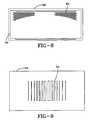
- FIG. 8is a diagram of one embodiment of a window of the present invention in which the lengths of the openings of the aperture generally change from one edge to another edge of the aperture.
- FIG. 9is a diagram of one embodiment of a tapered aperture of the present invention.
- FIG. 10is a plot of the transmission properties of an exemplary transmission region of the present invention over the 0.5 to 2 GHz frequency band.
- FIG. 11is a plot of the transmission properties of an exemplary transmission region of the present invention over the 2 to 18 GHz frequency band.
- FIG. 12is a plot of the transmission properties of an exemplary transmission region of the present invention over the 0.5 to 2 GHz frequency band.
- FIG. 13is a plot of the transmission properties of an exemplary transmission region of the present invention over the 2 to 18 GHz frequency band.
- FIG. 14is a plot of the transmission properties of an exemplary transmission region of the present invention over the 0.5 to 2 GHz frequency band.
- FIG. 15is a plot of the transmission properties of an exemplary transmission region of the present invention over the 2 to 18 GHz frequency band.
- FIG. 16is a plot of the transmission properties of an exemplary transmission region of the present invention over the 0.5 to 2 GHz frequency band.
- FIG. 17is a plot of the transmission properties of an exemplary transmission region of the present invention over the 2 to 18 GHz frequency band.
- FIG. 18is a diagram used to demonstrate the effect of one exemplary tapered aperture of the present invention.
- FIG. 19is a plot of the transmission coefficient versus distance across the aperture shown in FIG. 18 of one embodiment of an abruptly tapered aperture of the present invention.
- FIG. 20is a plot of the signal level as a function of position along the scan line shown in FIG. 18 one meter away from the embodiment of the tapered aperture shown in FIG. 19 .
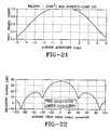
- FIG. 21is a plot of the transmission coefficient of one embodiment of a smoothly tapered aperture of the present invention.
- FIG. 22is a plot of the signal level as a function of position along the scan line shown in FIG. 18 one meter away from the embodiment of the tapered aperture shown in FIG. 21 .
- the present inventiongenerally relates to a region in a metallic or non-metallic panel that facilitates the transmission of RF signals with sidelobe control.
- the present inventionmay be utilized in any environment where metallic panels (or other non-metallic types of panels that block RF signals) are implemented.
- the present inventionmay be implemented in windows having a transparent, metallic layer including, but not limited to, vehicle windows, building windows, and other types of windows.
- the present inventionis not limited to uses with transparent or translucent panels. In other words, the present invention may also be implemented in opaque panels.
- the present inventionis primarily described herein with regard to facilitating the transmission of RF signals because many modern devices use RF communication.
- some embodiments of the present inventionmay be useful for some or all of the following frequency bands: (1) the cellular AMPS band (800-900 MHz); (2) the cellular digital (PCS) band (1750-1850 MHz); and (3) the GPS navigation band (1574 MHz).
- the present inventionmay also be useful for enabling the transmission of frequencies outside (i.e., above or below) these example RF bands. Accordingly, the present invention is not limited to certain apertures that facilitate the transmission of specific RF signals.
- FIG. 1shows an example of one embodiment of the present invention.
- the window 10is comprised of a sheet of dielectric material 12 and a metal layer 14 .
- the metal layer 14may traverse all or a portion of the dielectric material 12 .
- the metal layer 14may serve as a shield against RF signals.
- an aperture 16is defined in the metal layer 14 to facilitate the transmission of RF signals through the metal layer 14 .
- the window 10may be any desired type of window including, but not limited to, a vehicle window, a building window, or any other type of window.
- the dielectric material 12 of the window 10may be any material having desired dielectric characteristics.
- the dielectric material 12may be glass, plastic, or any other similar, suitable, or conventional dielectric material.
- An example of glassincludes, but is not limited to, safety glass.
- Examples of plasticinclude, but are not limited to, polycarbonate and plexiglass.
- the dielectric material 12may be comprised of a single layer or multiple layers.
- the metal layer 14may be secured to an outer surface or in between layers of the dielectric material 12 .
- the metal layer 14may be formed using any suitable manufacturing technique including, but not limited to, vacuum deposition (including, but not limited to, sputtering), extrusion, or any other similar technique.
- the metal layer 14may be vacuum deposited (e.g., sputtered) on an outer surface or in between layers of the dielectric material 12 .
- an apertureshall be understood to be comprised of at least one opening.
- the aperture 16is comprised of an array of openings. More particularly, the openings of the aperture 16 are slots in this example. In a variation of this embodiment, the openings may be interconnected such that there is actually one continuous opening.
- the aperture 16may be formed in the metal layer 14 using any suitable manufacturing technique. For instance, the metal layer 14 may be formed and then portions of the metal layer 14 may be removed to create the aperture 16 . For another example, the metal layer 14 and the aperture 16 may be simultaneously formed (i.e., no portions of the metal layer 14 are removed to form the aperture 16 ).
- the aperture 16is comprised of slots that are approximately vertically oriented.
- the slots of the aperture 16are approximately parallel to each other in this embodiment. Consequently, this particular embodiment is useful for facilitating the transmission of horizontally polarized signals.
- the embodiment of FIG. 1offers another significant benefit.
- the metal layer 14 of this exampleis adapted to conduct electricity.
- a bus 18is in electrical communication with a power source via a lead 20 .
- Another bus 22is in electrical communication with a common or ground line 24 .
- Electric currentis adapted to flow across the metal layer 14 between the buses 18 and 22 .
- the aperture 16is oriented in the direction of current flow. As a result, the current may flow between adjacent openings of the aperture 16 from bus 18 to bus 22 as opposed to flowing around the aperture 16 . This enables the heating to remain approximately uniform over the window 10 . In other words, there is not a “cool spot” at the location of the aperture 16 when the rest of the window 10 is being heated.
- this embodimentmay substantially limit or prevent hot spots that may otherwise be caused by excessive current flow around the corners and edges of the aperture. Nevertheless, it should be recognized that the aperture may be oriented in some embodiments of the present invention such that current may not flow between adjacent openings of the aperture.
- the aperture of FIG. 1is merely one example of a suitable aperture of the present invention.
- the openings of the aperture 16 of FIG. 1are approximately parallel, it should be recognized that the spacing between adjacent openings may be varied such that adjacent openings are not parallel.
- the openings of the aperture 16may have any suitable size and shape (not limited to slots), may be of any suitable number, and may be arranged in any suitable pattern and orientation to facilitate the transmission of signals in the desired frequency range.
- the design of the aperturemay be based on the theory of frequency selective surfaces (FSS). Utilizing the theory of frequency selective surfaces, the length, width, shape, orientation, and spacing of the opening(s) of the aperture may be selected to enable transmission of signals in the desired frequency bands.
- FSSfrequency selective surfaces
- FIG. 2illustrates another embodiment of the present invention.
- the window 26is comprised of a dielectric material 28 and a metal layer 30 .
- the aperture 32is approximately horizontally oriented between bus 34 and bus 36 . Consequently, current is adapted to flow between adjacent openings of the aperture 32 from bus 34 to bus 36 .
- FIG. 3shows another example of a FSS region.
- the FSS region 38is an aperture having zigzag openings that enables full polarization performance of the system.
- the aperturefacilitates the transmission of both vertically polarized and horizontally polarized signals and thus all other polarizations as linear combinations.
- the openings of the FSS region 38are oriented in the direction of current flow between bus 40 and bus 42 , thereby enabling substantially uniform heating over the area of the metal layer 44 .
- the angle of the tilt of the zigzags and the length of the legshave an impact on the polarization and frequency band performance of the FSS region 38 .
- the +45 degree tilt polarization electric field componentpropagates through the ⁇ 45 degree tilt portion of the pattern
- the ⁇ 45 degree tilt polarization electric field componentpropagates through the +45 degree tilt portion of the pattern.
- factors such as the tilt angle, the length of the legs, and the number of direction changesmay be varied in order to obtain the desired transmission characteristics of the FSS region 38 .
- FIG. 4illustrates another example of an aperture having zigzag openings.
- Each leg of the pattern 46has a length a.
- the spacing between adjacent openingsis b.
- FIG. 5is merely one example of an aperture having a broken pattern of openings.
- a broken pattern of openingsincludes a pattern in which there is at least one gap between adjacent legs of at least one of the zigzags of the aperture, i.e., a discontinuous zigzag. It should also be recognized that any other type of aperture (including, but not limited to, the apertures of FIGS. 1 , 2 , and 3 ) may be given a broken pattern by inserting a gap at any point in an opening.
- FIG. 6illustrates an example of an aperture that utilizes fill-in or makeup openings along the edges of the aperture.
- fill-in openings 50are used along opposing edges of the zigzags, thereby giving the aperture generally smooth edges. Some or all of the openings 50 may be useful to lessen any non-uniformity in the current flow caused by the corners of the pattern.
- the fill-in openings 50may be adapted to direct the heating current into the inside corner spaces. Such an embodiment helps to fill in the heater current to provide enhanced uniform heating across the overall aperture pattern.
- FIG. 7shows an example of a window 52 that has an aperture 54 and an aperture 56 . Multiple apertures may be useful to improve the transmission characteristics of the window 52 .
- FIG. 8illustrates another window 58 that has multiple FSS regions.
- the respective lengths of the individual openingsgenerally increase from one side of the aperture to an opposite side of the aperture. This embodiment may be useful to account for any curvature of the window 58 .
- the total electrical resistance of the metal layer 62may be made approximately uniform by varying the respective lengths of the openings to control resistance. In effect, the longer openings force the electrical current to flow in a longer path, thereby correcting for any curvature of the window 58 .
- a radio signalpasses through an aperture in a metal layer, sidelobes may occur in the transmitted signal.
- the lobeswould be inside the passenger compartment of the vehicle. Consequently, the user of a handheld wireless device, e.g., a cellular phone, may find that changes in the position of the handheld device may cause changes in the signal strength.
- the potential effect of sidelobesmay be taken into consideration when designing an aperture.
- the far field pattern of an apertureis the Fourier transform of the signal distribution over the aperture. Consequently, standard Fourier windowing techniques may be used to suppress sidelobe patterns in the transmitted signal. Examples of Fourier windowing techniques are those that may use a taper in the transmission amplitude and/or the phase to suppress lobing effects on the other side of an aperture.
- FIG. 9illustrates one example of a tapered aperture.
- a tapered aperturemay include any of the optional or preferred features of the other embodiments of the present invention. For instance, an aperture having zigzag openings may be tapered.
- an aperture 64is shown in a panel 66.
- the spacing, shape, and size of the openingsvary across the aperture to control the RF transmission coefficient across the aperture 64 .
- the openingsget gradually wider toward the center of the aperture, and the spacing between the openings is generally more narrow toward the center of the aperture.
- the spacing between the openingsmay be about the same, and the width of the openings may be varied to control the amount of tapering.
- the width of the openingsmay be about the same, and the spacing between the openings may be varied to control the amount of tapering.
- the taper in the transmission coefficientmay be over any desired range.
- the relative transmission coefficientis preferably at least 90%, more preferably at least 95%, still more preferably about 100%, near the center of the aperture and less than about 40%, more preferably less than about 30%, still more preferably less than about 20%, at an edge of an aperture.
- the term relative transmission coefficientrefers to the ratio of the transmission coefficient through the aperture relative to what the transmission coefficient would be if there was no metallic panel to limit transmission (i.e., a nominal or baseline value).
- there is a taper in the transmission coefficientsuch that the relative transmission coefficient is nearly 100% near the center of an aperture and approaches 0% at the edge.
- the taperingmay occur over any desired portion(s) of an aperture.
- the taperingoccurs over at least 10%, more preferably over at least 20%, still more preferably over at least 30%, even more preferably over at least 40%, of an edge portion of an aperture relative to the distance to the center of the aperture. Nevertheless, it should be recognized that less tapering over an edge portion of an aperture may be desired for certain applications.
- test resultsare provided for both orthogonal (vertical) and parallel (horizontal) polarizations in the 500 MHz to 18 GHz frequency band.
- the resultsare based on simulations using a periodic moment method (PMM) computer calculation code. All data in these figures is normalized with respect to free space.
- PMMperiodic moment method
- FIGS. 10 and 11illustrate the transmission properties of one embodiment of an aperture of the present invention having broken, zigzag openings.
- the tested embodimentwas similar to the aperture of FIG. 5 , wherein: the length c was about 41.4 mm; the spacing d was about 2 mm; the gap e was about 1 mm; and the angle between the opening segments, i.e., legs, was about 90 degrees.
- FIG. 10it can be seen that this design offers superior performance for horizontally polarized signals in the 0.5 to 2 GHz band.
- FIG. 11shows a null around 10 GHz, but there are also frequency regions where the transmission coefficient is about 5 dB. Using the design principles of the present invention, the frequency at which the null occurs may be shifted by varying the size c of the legs.
- FIGS. 12 and 13show the test results for an embodiment similar to the aperture of FIG. 4 .
- the length awas about 41.4 mm
- the spacing bwas about 2 mm
- the angle between the opening segments, i.e., legswas about 90 degrees.
- this embodimentprovides a better transmission coefficient for horizontally polarized signals.
- this apertureshows good transmission properties around 10 GHz for both horizontally and vertically polarized signals.
- FIGS. 14 and 15The test results of another aperture having zigzag openings are shown in FIGS. 14 and 15 .
- This apertureis also similar to FIG. 4 , wherein: the length a was about 53.88 mm; the spacing b was about 2 mm; and the angle between the opening segments, i.e., legs, was about 70 degrees.
- this embodimentprovides an improvement in the transmission performance for orthogonal polarization. There are nulls around 9 and 14 GHz, but overall the transmission characteristics are good.
- FIGS. 16 and 17show the transmission characteristics of still another aperture in the 0.5 to 2 GHz and the 2 to 18 GHz frequency bands, respectively.
- the aperturewas similar to the embodiment shown in FIG. 4 .
- the aperturehad a length a of about 35.92 mm and a spacing b of about 2 mm.
- the angle between the opening segments, i.e., legs,was about 70 degrees.
- FIG. 17shows nulls around 7 and 14 GHz, but the response around the 10 GHz frequency region is good for both vertical and horizontal polarizations.
- FIG. 18is a diagram used to demonstrate the effect of a tapered aperture.
- the tapered aperturehad a width of about 10 cm.
- the transmission propertieswere simulated one meter from the tapered aperture.
- the lobing patternone meter from a sharp edge (20% coverage cosine-on-a-pedestal) aperture is shown.
- the cosine taperingonly effects 10% of the aperture at the left edge and the right edge (for a total of 20%).
- the lobing pattern in this exampleis about ⁇ 13 dB with respect to the main lobe.
- FIGS. 21 and 22show the cross aperture transmission coefficient and the resulting signal level as a function of position one meter away from another embodiment of a tapered aperture.
- an 80% coverage cosine-on-a-pedestal aperturei.e., the cosine tapering effects the left and right 40% for a total of 80%
- This embodimentreduced the side lobe to ⁇ 22 dB with respect to the main lobe. Consequently, these examples show that the use of tapering significantly reduces the lobing effect.
Landscapes
- Engineering & Computer Science (AREA)
- Civil Engineering (AREA)
- Structural Engineering (AREA)
- Aerials With Secondary Devices (AREA)
Abstract
Description
Claims (30)
Priority Applications (4)
| Application Number | Priority Date | Filing Date | Title |
|---|---|---|---|
| US10/310,643US6860081B2 (en) | 2002-12-04 | 2002-12-04 | Sidelobe controlled radio transmission region in metallic panel |
| AU2003297578AAU2003297578A1 (en) | 2002-12-04 | 2003-11-26 | Sidelobe controlled radio transmission region in metallic panel |
| PCT/US2003/037935WO2004051870A2 (en) | 2002-12-04 | 2003-11-26 | Sidelobe controlled radio transmission region in metallic panel |
| US11/067,793US20060010794A1 (en) | 2002-12-04 | 2005-02-28 | Sidelobe controlled radio transmission region in metallic panel |
Applications Claiming Priority (1)
| Application Number | Priority Date | Filing Date | Title |
|---|---|---|---|
| US10/310,643US6860081B2 (en) | 2002-12-04 | 2002-12-04 | Sidelobe controlled radio transmission region in metallic panel |
Related Child Applications (1)
| Application Number | Title | Priority Date | Filing Date |
|---|---|---|---|
| US11/067,793DivisionUS20060010794A1 (en) | 2002-12-04 | 2005-02-28 | Sidelobe controlled radio transmission region in metallic panel |
Publications (2)
| Publication Number | Publication Date |
|---|---|
| US20040107641A1 US20040107641A1 (en) | 2004-06-10 |
| US6860081B2true US6860081B2 (en) | 2005-03-01 |
Family
ID=32468080
Family Applications (2)
| Application Number | Title | Priority Date | Filing Date |
|---|---|---|---|
| US10/310,643Expired - Fee RelatedUS6860081B2 (en) | 2002-12-04 | 2002-12-04 | Sidelobe controlled radio transmission region in metallic panel |
| US11/067,793AbandonedUS20060010794A1 (en) | 2002-12-04 | 2005-02-28 | Sidelobe controlled radio transmission region in metallic panel |
Family Applications After (1)
| Application Number | Title | Priority Date | Filing Date |
|---|---|---|---|
| US11/067,793AbandonedUS20060010794A1 (en) | 2002-12-04 | 2005-02-28 | Sidelobe controlled radio transmission region in metallic panel |
Country Status (3)
| Country | Link |
|---|---|
| US (2) | US6860081B2 (en) |
| AU (1) | AU2003297578A1 (en) |
| WO (1) | WO2004051870A2 (en) |
Cited By (10)
| Publication number | Priority date | Publication date | Assignee | Title |
|---|---|---|---|---|
| US20060012513A1 (en)* | 2003-01-31 | 2006-01-19 | The Ohio State University | Radar system using RF noise |
| US20060010794A1 (en)* | 2002-12-04 | 2006-01-19 | The Ohio State University | Sidelobe controlled radio transmission region in metallic panel |
| US20060022866A1 (en)* | 2002-01-17 | 2006-02-02 | The Ohio State University | Vehicle obstacle warning radar |
| US20150229030A1 (en)* | 2014-02-11 | 2015-08-13 | Pittsburgh Glass Works, Llc | Heatable window with high-pass frequency selective surface |
| EP2510745B1 (en) | 2009-12-11 | 2016-02-17 | Saint-Gobain Glass France | Coated pane with heatable communication window |
| US9425516B2 (en) | 2012-07-06 | 2016-08-23 | The Ohio State University | Compact dual band GNSS antenna design |
| US9625685B2 (en) | 2011-01-14 | 2017-04-18 | Asahi Glass Company, Limited | Automobile window glass |
| US10792894B2 (en) | 2015-10-15 | 2020-10-06 | Saint-Gobain Performance Plastics Corporation | Seasonal solar control composite |
| US20210050881A1 (en)* | 2019-08-12 | 2021-02-18 | Antwave Intellectual Property Limited | Slotted electrically conductive structure for improving indoor penetration of wireless communication signal |
| US11285705B2 (en)* | 2016-10-18 | 2022-03-29 | Samsung Electronics Co., Ltd. | Film laminate and window product comprising same |
Families Citing this family (191)
| Publication number | Priority date | Publication date | Assignee | Title |
|---|---|---|---|---|
| GB201019601D0 (en)* | 2010-11-19 | 2010-12-29 | Pilkington Group Ltd | Glazing with frequency selective coating |
| WO2012152339A1 (en)* | 2011-05-12 | 2012-11-15 | Telefonaktiebolaget L M Ericsson (Publ) | A metallized structure layer for a window arrangement |
| US10218227B2 (en) | 2014-05-07 | 2019-02-26 | Energous Corporation | Compact PIFA antenna |
| US10063064B1 (en) | 2014-05-23 | 2018-08-28 | Energous Corporation | System and method for generating a power receiver identifier in a wireless power network |
| US10211680B2 (en) | 2013-07-19 | 2019-02-19 | Energous Corporation | Method for 3 dimensional pocket-forming |
| US9941747B2 (en) | 2014-07-14 | 2018-04-10 | Energous Corporation | System and method for manually selecting and deselecting devices to charge in a wireless power network |
| US11502551B2 (en) | 2012-07-06 | 2022-11-15 | Energous Corporation | Wirelessly charging multiple wireless-power receivers using different subsets of an antenna array to focus energy at different locations |
| US10063105B2 (en) | 2013-07-11 | 2018-08-28 | Energous Corporation | Proximity transmitters for wireless power charging systems |
| US9893768B2 (en) | 2012-07-06 | 2018-02-13 | Energous Corporation | Methodology for multiple pocket-forming |
| US9853692B1 (en) | 2014-05-23 | 2017-12-26 | Energous Corporation | Systems and methods for wireless power transmission |
| US10256657B2 (en) | 2015-12-24 | 2019-04-09 | Energous Corporation | Antenna having coaxial structure for near field wireless power charging |
| US9948135B2 (en) | 2015-09-22 | 2018-04-17 | Energous Corporation | Systems and methods for identifying sensitive objects in a wireless charging transmission field |
| US9843213B2 (en) | 2013-08-06 | 2017-12-12 | Energous Corporation | Social power sharing for mobile devices based on pocket-forming |
| US9825674B1 (en) | 2014-05-23 | 2017-11-21 | Energous Corporation | Enhanced transmitter that selects configurations of antenna elements for performing wireless power transmission and receiving functions |
| US9991741B1 (en) | 2014-07-14 | 2018-06-05 | Energous Corporation | System for tracking and reporting status and usage information in a wireless power management system |
| US9143000B2 (en) | 2012-07-06 | 2015-09-22 | Energous Corporation | Portable wireless charging pad |
| US10992187B2 (en) | 2012-07-06 | 2021-04-27 | Energous Corporation | System and methods of using electromagnetic waves to wirelessly deliver power to electronic devices |
| US9887584B1 (en) | 2014-08-21 | 2018-02-06 | Energous Corporation | Systems and methods for a configuration web service to provide configuration of a wireless power transmitter within a wireless power transmission system |
| US10038337B1 (en) | 2013-09-16 | 2018-07-31 | Energous Corporation | Wireless power supply for rescue devices |
| US9824815B2 (en) | 2013-05-10 | 2017-11-21 | Energous Corporation | Wireless charging and powering of healthcare gadgets and sensors |
| US9847677B1 (en) | 2013-10-10 | 2017-12-19 | Energous Corporation | Wireless charging and powering of healthcare gadgets and sensors |
| US10263432B1 (en) | 2013-06-25 | 2019-04-16 | Energous Corporation | Multi-mode transmitter with an antenna array for delivering wireless power and providing Wi-Fi access |
| US9882427B2 (en) | 2013-05-10 | 2018-01-30 | Energous Corporation | Wireless power delivery using a base station to control operations of a plurality of wireless power transmitters |
| US9787103B1 (en) | 2013-08-06 | 2017-10-10 | Energous Corporation | Systems and methods for wirelessly delivering power to electronic devices that are unable to communicate with a transmitter |
| US9812890B1 (en) | 2013-07-11 | 2017-11-07 | Energous Corporation | Portable wireless charging pad |
| US10211674B1 (en) | 2013-06-12 | 2019-02-19 | Energous Corporation | Wireless charging using selected reflectors |
| US9838083B2 (en) | 2014-07-21 | 2017-12-05 | Energous Corporation | Systems and methods for communication with remote management systems |
| US9876379B1 (en) | 2013-07-11 | 2018-01-23 | Energous Corporation | Wireless charging and powering of electronic devices in a vehicle |
| US9847679B2 (en) | 2014-05-07 | 2017-12-19 | Energous Corporation | System and method for controlling communication between wireless power transmitter managers |
| US10206185B2 (en) | 2013-05-10 | 2019-02-12 | Energous Corporation | System and methods for wireless power transmission to an electronic device in accordance with user-defined restrictions |
| US9859756B2 (en) | 2012-07-06 | 2018-01-02 | Energous Corporation | Transmittersand methods for adjusting wireless power transmission based on information from receivers |
| US10141768B2 (en) | 2013-06-03 | 2018-11-27 | Energous Corporation | Systems and methods for maximizing wireless power transfer efficiency by instructing a user to change a receiver device's position |
| US9252628B2 (en) | 2013-05-10 | 2016-02-02 | Energous Corporation | Laptop computer as a transmitter for wireless charging |
| US10148097B1 (en) | 2013-11-08 | 2018-12-04 | Energous Corporation | Systems and methods for using a predetermined number of communication channels of a wireless power transmitter to communicate with different wireless power receivers |
| US9882430B1 (en) | 2014-05-07 | 2018-01-30 | Energous Corporation | Cluster management of transmitters in a wireless power transmission system |
| US10211682B2 (en) | 2014-05-07 | 2019-02-19 | Energous Corporation | Systems and methods for controlling operation of a transmitter of a wireless power network based on user instructions received from an authenticated computing device powered or charged by a receiver of the wireless power network |
| US9941707B1 (en) | 2013-07-19 | 2018-04-10 | Energous Corporation | Home base station for multiple room coverage with multiple transmitters |
| US10381880B2 (en) | 2014-07-21 | 2019-08-13 | Energous Corporation | Integrated antenna structure arrays for wireless power transmission |
| US10291066B1 (en) | 2014-05-07 | 2019-05-14 | Energous Corporation | Power transmission control systems and methods |
| US10128693B2 (en) | 2014-07-14 | 2018-11-13 | Energous Corporation | System and method for providing health safety in a wireless power transmission system |
| US9859757B1 (en) | 2013-07-25 | 2018-01-02 | Energous Corporation | Antenna tile arrangements in electronic device enclosures |
| US9843201B1 (en) | 2012-07-06 | 2017-12-12 | Energous Corporation | Wireless power transmitter that selects antenna sets for transmitting wireless power to a receiver based on location of the receiver, and methods of use thereof |
| US10230266B1 (en) | 2014-02-06 | 2019-03-12 | Energous Corporation | Wireless power receivers that communicate status data indicating wireless power transmission effectiveness with a transmitter using a built-in communications component of a mobile device, and methods of use thereof |
| US20150326070A1 (en) | 2014-05-07 | 2015-11-12 | Energous Corporation | Methods and Systems for Maximum Power Point Transfer in Receivers |
| US10992185B2 (en) | 2012-07-06 | 2021-04-27 | Energous Corporation | Systems and methods of using electromagnetic waves to wirelessly deliver power to game controllers |
| US10439448B2 (en) | 2014-08-21 | 2019-10-08 | Energous Corporation | Systems and methods for automatically testing the communication between wireless power transmitter and wireless power receiver |
| US10193396B1 (en) | 2014-05-07 | 2019-01-29 | Energous Corporation | Cluster management of transmitters in a wireless power transmission system |
| US9876648B2 (en) | 2014-08-21 | 2018-01-23 | Energous Corporation | System and method to control a wireless power transmission system by configuration of wireless power transmission control parameters |
| US10128699B2 (en) | 2014-07-14 | 2018-11-13 | Energous Corporation | Systems and methods of providing wireless power using receiver device sensor inputs |
| US9887739B2 (en) | 2012-07-06 | 2018-02-06 | Energous Corporation | Systems and methods for wireless power transmission by comparing voltage levels associated with power waves transmitted by antennas of a plurality of antennas of a transmitter to determine appropriate phase adjustments for the power waves |
| US10090886B1 (en) | 2014-07-14 | 2018-10-02 | Energous Corporation | System and method for enabling automatic charging schedules in a wireless power network to one or more devices |
| US9438045B1 (en) | 2013-05-10 | 2016-09-06 | Energous Corporation | Methods and systems for maximum power point transfer in receivers |
| US9368020B1 (en) | 2013-05-10 | 2016-06-14 | Energous Corporation | Off-premises alert system and method for wireless power receivers in a wireless power network |
| US10224758B2 (en) | 2013-05-10 | 2019-03-05 | Energous Corporation | Wireless powering of electronic devices with selective delivery range |
| US10124754B1 (en) | 2013-07-19 | 2018-11-13 | Energous Corporation | Wireless charging and powering of electronic sensors in a vehicle |
| US9124125B2 (en) | 2013-05-10 | 2015-09-01 | Energous Corporation | Wireless power transmission with selective range |
| US9906065B2 (en) | 2012-07-06 | 2018-02-27 | Energous Corporation | Systems and methods of transmitting power transmission waves based on signals received at first and second subsets of a transmitter's antenna array |
| US10075008B1 (en) | 2014-07-14 | 2018-09-11 | Energous Corporation | Systems and methods for manually adjusting when receiving electronic devices are scheduled to receive wirelessly delivered power from a wireless power transmitter in a wireless power network |
| US9793758B2 (en) | 2014-05-23 | 2017-10-17 | Energous Corporation | Enhanced transmitter using frequency control for wireless power transmission |
| US10199849B1 (en) | 2014-08-21 | 2019-02-05 | Energous Corporation | Method for automatically testing the operational status of a wireless power receiver in a wireless power transmission system |
| US9831718B2 (en) | 2013-07-25 | 2017-11-28 | Energous Corporation | TV with integrated wireless power transmitter |
| US10141791B2 (en) | 2014-05-07 | 2018-11-27 | Energous Corporation | Systems and methods for controlling communications during wireless transmission of power using application programming interfaces |
| US10063106B2 (en) | 2014-05-23 | 2018-08-28 | Energous Corporation | System and method for a self-system analysis in a wireless power transmission network |
| US10050462B1 (en) | 2013-08-06 | 2018-08-14 | Energous Corporation | Social power sharing for mobile devices based on pocket-forming |
| US9806564B2 (en) | 2014-05-07 | 2017-10-31 | Energous Corporation | Integrated rectifier and boost converter for wireless power transmission |
| US9966765B1 (en) | 2013-06-25 | 2018-05-08 | Energous Corporation | Multi-mode transmitter |
| US20140008993A1 (en) | 2012-07-06 | 2014-01-09 | DvineWave Inc. | Methodology for pocket-forming |
| US9867062B1 (en) | 2014-07-21 | 2018-01-09 | Energous Corporation | System and methods for using a remote server to authorize a receiving device that has requested wireless power and to determine whether another receiving device should request wireless power in a wireless power transmission system |
| US10243414B1 (en) | 2014-05-07 | 2019-03-26 | Energous Corporation | Wearable device with wireless power and payload receiver |
| US10223717B1 (en) | 2014-05-23 | 2019-03-05 | Energous Corporation | Systems and methods for payment-based authorization of wireless power transmission service |
| US9954374B1 (en) | 2014-05-23 | 2018-04-24 | Energous Corporation | System and method for self-system analysis for detecting a fault in a wireless power transmission Network |
| US9876394B1 (en) | 2014-05-07 | 2018-01-23 | Energous Corporation | Boost-charger-boost system for enhanced power delivery |
| US10224982B1 (en) | 2013-07-11 | 2019-03-05 | Energous Corporation | Wireless power transmitters for transmitting wireless power and tracking whether wireless power receivers are within authorized locations |
| US9912199B2 (en) | 2012-07-06 | 2018-03-06 | Energous Corporation | Receivers for wireless power transmission |
| US9899873B2 (en) | 2014-05-23 | 2018-02-20 | Energous Corporation | System and method for generating a power receiver identifier in a wireless power network |
| US9923386B1 (en) | 2012-07-06 | 2018-03-20 | Energous Corporation | Systems and methods for wireless power transmission by modifying a number of antenna elements used to transmit power waves to a receiver |
| US9900057B2 (en) | 2012-07-06 | 2018-02-20 | Energous Corporation | Systems and methods for assigning groups of antenas of a wireless power transmitter to different wireless power receivers, and determining effective phases to use for wirelessly transmitting power using the assigned groups of antennas |
| US10270261B2 (en) | 2015-09-16 | 2019-04-23 | Energous Corporation | Systems and methods of object detection in wireless power charging systems |
| US10291055B1 (en) | 2014-12-29 | 2019-05-14 | Energous Corporation | Systems and methods for controlling far-field wireless power transmission based on battery power levels of a receiving device |
| US10312715B2 (en) | 2015-09-16 | 2019-06-04 | Energous Corporation | Systems and methods for wireless power charging |
| US10103582B2 (en) | 2012-07-06 | 2018-10-16 | Energous Corporation | Transmitters for wireless power transmission |
| US9853458B1 (en) | 2014-05-07 | 2017-12-26 | Energous Corporation | Systems and methods for device and power receiver pairing |
| US9893554B2 (en) | 2014-07-14 | 2018-02-13 | Energous Corporation | System and method for providing health safety in a wireless power transmission system |
| US12057715B2 (en) | 2012-07-06 | 2024-08-06 | Energous Corporation | Systems and methods of wirelessly delivering power to a wireless-power receiver device in response to a change of orientation of the wireless-power receiver device |
| US10965164B2 (en) | 2012-07-06 | 2021-03-30 | Energous Corporation | Systems and methods of wirelessly delivering power to a receiver device |
| US9899861B1 (en) | 2013-10-10 | 2018-02-20 | Energous Corporation | Wireless charging methods and systems for game controllers, based on pocket-forming |
| US10205239B1 (en) | 2014-05-07 | 2019-02-12 | Energous Corporation | Compact PIFA antenna |
| US9859797B1 (en) | 2014-05-07 | 2018-01-02 | Energous Corporation | Synchronous rectifier design for wireless power receiver |
| US10186913B2 (en) | 2012-07-06 | 2019-01-22 | Energous Corporation | System and methods for pocket-forming based on constructive and destructive interferences to power one or more wireless power receivers using a wireless power transmitter including a plurality of antennas |
| US10199835B2 (en) | 2015-12-29 | 2019-02-05 | Energous Corporation | Radar motion detection using stepped frequency in wireless power transmission system |
| US9891669B2 (en) | 2014-08-21 | 2018-02-13 | Energous Corporation | Systems and methods for a configuration web service to provide configuration of a wireless power transmitter within a wireless power transmission system |
| US20140368048A1 (en)* | 2013-05-10 | 2014-12-18 | DvineWave Inc. | Wireless charging with reflectors |
| US9893555B1 (en) | 2013-10-10 | 2018-02-13 | Energous Corporation | Wireless charging of tools using a toolbox transmitter |
| US9939864B1 (en) | 2014-08-21 | 2018-04-10 | Energous Corporation | System and method to control a wireless power transmission system by configuration of wireless power transmission control parameters |
| US9941754B2 (en) | 2012-07-06 | 2018-04-10 | Energous Corporation | Wireless power transmission with selective range |
| US10090699B1 (en) | 2013-11-01 | 2018-10-02 | Energous Corporation | Wireless powered house |
| US9973021B2 (en) | 2012-07-06 | 2018-05-15 | Energous Corporation | Receivers for wireless power transmission |
| US9871398B1 (en) | 2013-07-01 | 2018-01-16 | Energous Corporation | Hybrid charging method for wireless power transmission based on pocket-forming |
| US10008889B2 (en) | 2014-08-21 | 2018-06-26 | Energous Corporation | Method for automatically testing the operational status of a wireless power receiver in a wireless power transmission system |
| EP2947957B1 (en) | 2013-01-21 | 2017-11-22 | Asahi Glass Company, Limited | Sheet material for electrically-heated window |
| WO2014112649A1 (en) | 2013-01-21 | 2014-07-24 | 旭硝子株式会社 | Electrically heated plate-shaped body for window |
| US9873169B2 (en) | 2013-03-07 | 2018-01-23 | Saint-Gobain Glass France | Coated pane with partially de-coated regions |
| EP2984707B1 (en)* | 2013-04-09 | 2020-08-05 | Siemens Mobility GmbH | Metal-coated windowpane, particularly for rail vehicles |
| US9843763B2 (en) | 2013-05-10 | 2017-12-12 | Energous Corporation | TV system with wireless power transmitter |
| US9537357B2 (en) | 2013-05-10 | 2017-01-03 | Energous Corporation | Wireless sound charging methods and systems for game controllers, based on pocket-forming |
| US9538382B2 (en) | 2013-05-10 | 2017-01-03 | Energous Corporation | System and method for smart registration of wireless power receivers in a wireless power network |
| US9866279B2 (en) | 2013-05-10 | 2018-01-09 | Energous Corporation | Systems and methods for selecting which power transmitter should deliver wireless power to a receiving device in a wireless power delivery network |
| US9419443B2 (en) | 2013-05-10 | 2016-08-16 | Energous Corporation | Transducer sound arrangement for pocket-forming |
| US9819230B2 (en) | 2014-05-07 | 2017-11-14 | Energous Corporation | Enhanced receiver for wireless power transmission |
| US10103552B1 (en) | 2013-06-03 | 2018-10-16 | Energous Corporation | Protocols for authenticated wireless power transmission |
| US10003211B1 (en) | 2013-06-17 | 2018-06-19 | Energous Corporation | Battery life of portable electronic devices |
| US10021523B2 (en) | 2013-07-11 | 2018-07-10 | Energous Corporation | Proximity transmitters for wireless power charging systems |
| US9979440B1 (en) | 2013-07-25 | 2018-05-22 | Energous Corporation | Antenna tile arrangements configured to operate as one functional unit |
| US9935482B1 (en) | 2014-02-06 | 2018-04-03 | Energous Corporation | Wireless power transmitters that transmit at determined times based on power availability and consumption at a receiving mobile device |
| US10075017B2 (en) | 2014-02-06 | 2018-09-11 | Energous Corporation | External or internal wireless power receiver with spaced-apart antenna elements for charging or powering mobile devices using wirelessly delivered power |
| CN110027510B (en) | 2014-04-28 | 2022-05-10 | Agc株式会社 | Plate-shaped body for electric heating window |
| US10158257B2 (en) | 2014-05-01 | 2018-12-18 | Energous Corporation | System and methods for using sound waves to wirelessly deliver power to electronic devices |
| US9966784B2 (en) | 2014-06-03 | 2018-05-08 | Energous Corporation | Systems and methods for extending battery life of portable electronic devices charged by sound |
| US9973008B1 (en) | 2014-05-07 | 2018-05-15 | Energous Corporation | Wireless power receiver with boost converters directly coupled to a storage element |
| US9800172B1 (en) | 2014-05-07 | 2017-10-24 | Energous Corporation | Integrated rectifier and boost converter for boosting voltage received from wireless power transmission waves |
| US10153645B1 (en) | 2014-05-07 | 2018-12-11 | Energous Corporation | Systems and methods for designating a master power transmitter in a cluster of wireless power transmitters |
| US10153653B1 (en) | 2014-05-07 | 2018-12-11 | Energous Corporation | Systems and methods for using application programming interfaces to control communications between a transmitter and a receiver |
| US10170917B1 (en) | 2014-05-07 | 2019-01-01 | Energous Corporation | Systems and methods for managing and controlling a wireless power network by establishing time intervals during which receivers communicate with a transmitter |
| US9876536B1 (en) | 2014-05-23 | 2018-01-23 | Energous Corporation | Systems and methods for assigning groups of antennas to transmit wireless power to different wireless power receivers |
| US9871301B2 (en) | 2014-07-21 | 2018-01-16 | Energous Corporation | Integrated miniature PIFA with artificial magnetic conductor metamaterials |
| US10116143B1 (en) | 2014-07-21 | 2018-10-30 | Energous Corporation | Integrated antenna arrays for wireless power transmission |
| US10068703B1 (en) | 2014-07-21 | 2018-09-04 | Energous Corporation | Integrated miniature PIFA with artificial magnetic conductor metamaterials |
| US9965009B1 (en) | 2014-08-21 | 2018-05-08 | Energous Corporation | Systems and methods for assigning a power receiver to individual power transmitters based on location of the power receiver |
| US9917477B1 (en) | 2014-08-21 | 2018-03-13 | Energous Corporation | Systems and methods for automatically testing the communication between power transmitter and wireless receiver |
| US10122415B2 (en) | 2014-12-27 | 2018-11-06 | Energous Corporation | Systems and methods for assigning a set of antennas of a wireless power transmitter to a wireless power receiver based on a location of the wireless power receiver |
| US9893535B2 (en) | 2015-02-13 | 2018-02-13 | Energous Corporation | Systems and methods for determining optimal charging positions to maximize efficiency of power received from wirelessly delivered sound wave energy |
| US12283828B2 (en) | 2015-09-15 | 2025-04-22 | Energous Corporation | Receiver devices configured to determine location within a transmission field |
| US9906275B2 (en) | 2015-09-15 | 2018-02-27 | Energous Corporation | Identifying receivers in a wireless charging transmission field |
| US10523033B2 (en) | 2015-09-15 | 2019-12-31 | Energous Corporation | Receiver devices configured to determine location within a transmission field |
| US9941752B2 (en) | 2015-09-16 | 2018-04-10 | Energous Corporation | Systems and methods of object detection in wireless power charging systems |
| US10158259B1 (en) | 2015-09-16 | 2018-12-18 | Energous Corporation | Systems and methods for identifying receivers in a transmission field by transmitting exploratory power waves towards different segments of a transmission field |
| US9893538B1 (en) | 2015-09-16 | 2018-02-13 | Energous Corporation | Systems and methods of object detection in wireless power charging systems |
| US10008875B1 (en) | 2015-09-16 | 2018-06-26 | Energous Corporation | Wireless power transmitter configured to transmit power waves to a predicted location of a moving wireless power receiver |
| US10199850B2 (en) | 2015-09-16 | 2019-02-05 | Energous Corporation | Systems and methods for wirelessly transmitting power from a transmitter to a receiver by determining refined locations of the receiver in a segmented transmission field associated with the transmitter |
| US9871387B1 (en) | 2015-09-16 | 2018-01-16 | Energous Corporation | Systems and methods of object detection using one or more video cameras in wireless power charging systems |
| US10186893B2 (en) | 2015-09-16 | 2019-01-22 | Energous Corporation | Systems and methods for real time or near real time wireless communications between a wireless power transmitter and a wireless power receiver |
| US11710321B2 (en) | 2015-09-16 | 2023-07-25 | Energous Corporation | Systems and methods of object detection in wireless power charging systems |
| US10778041B2 (en) | 2015-09-16 | 2020-09-15 | Energous Corporation | Systems and methods for generating power waves in a wireless power transmission system |
| US10211685B2 (en) | 2015-09-16 | 2019-02-19 | Energous Corporation | Systems and methods for real or near real time wireless communications between a wireless power transmitter and a wireless power receiver |
| US10135295B2 (en) | 2015-09-22 | 2018-11-20 | Energous Corporation | Systems and methods for nullifying energy levels for wireless power transmission waves |
| US10033222B1 (en) | 2015-09-22 | 2018-07-24 | Energous Corporation | Systems and methods for determining and generating a waveform for wireless power transmission waves |
| US10027168B2 (en) | 2015-09-22 | 2018-07-17 | Energous Corporation | Systems and methods for generating and transmitting wireless power transmission waves using antennas having a spacing that is selected by the transmitter |
| US10050470B1 (en) | 2015-09-22 | 2018-08-14 | Energous Corporation | Wireless power transmission device having antennas oriented in three dimensions |
| US10128686B1 (en) | 2015-09-22 | 2018-11-13 | Energous Corporation | Systems and methods for identifying receiver locations using sensor technologies |
| US10135294B1 (en) | 2015-09-22 | 2018-11-20 | Energous Corporation | Systems and methods for preconfiguring transmission devices for power wave transmissions based on location data of one or more receivers |
| US10020678B1 (en) | 2015-09-22 | 2018-07-10 | Energous Corporation | Systems and methods for selecting antennas to generate and transmit power transmission waves |
| US10153660B1 (en) | 2015-09-22 | 2018-12-11 | Energous Corporation | Systems and methods for preconfiguring sensor data for wireless charging systems |
| US10333332B1 (en) | 2015-10-13 | 2019-06-25 | Energous Corporation | Cross-polarized dipole antenna |
| US10734717B2 (en) | 2015-10-13 | 2020-08-04 | Energous Corporation | 3D ceramic mold antenna |
| US9899744B1 (en) | 2015-10-28 | 2018-02-20 | Energous Corporation | Antenna for wireless charging systems |
| US9853485B2 (en) | 2015-10-28 | 2017-12-26 | Energous Corporation | Antenna for wireless charging systems |
| US10135112B1 (en) | 2015-11-02 | 2018-11-20 | Energous Corporation | 3D antenna mount |
| US10063108B1 (en) | 2015-11-02 | 2018-08-28 | Energous Corporation | Stamped three-dimensional antenna |
| US10027180B1 (en) | 2015-11-02 | 2018-07-17 | Energous Corporation | 3D triple linear antenna that acts as heat sink |
| US10186892B2 (en) | 2015-12-24 | 2019-01-22 | Energous Corporation | Receiver device with antennas positioned in gaps |
| US10320446B2 (en) | 2015-12-24 | 2019-06-11 | Energous Corporation | Miniaturized highly-efficient designs for near-field power transfer system |
| US10079515B2 (en) | 2016-12-12 | 2018-09-18 | Energous Corporation | Near-field RF charging pad with multi-band antenna element with adaptive loading to efficiently charge an electronic device at any position on the pad |
| US11863001B2 (en) | 2015-12-24 | 2024-01-02 | Energous Corporation | Near-field antenna for wireless power transmission with antenna elements that follow meandering patterns |
| US10256677B2 (en) | 2016-12-12 | 2019-04-09 | Energous Corporation | Near-field RF charging pad with adaptive loading to efficiently charge an electronic device at any position on the pad |
| US10038332B1 (en) | 2015-12-24 | 2018-07-31 | Energous Corporation | Systems and methods of wireless power charging through multiple receiving devices |
| US10027159B2 (en) | 2015-12-24 | 2018-07-17 | Energous Corporation | Antenna for transmitting wireless power signals |
| US10164478B2 (en) | 2015-12-29 | 2018-12-25 | Energous Corporation | Modular antenna boards in wireless power transmission systems |
| US10923954B2 (en) | 2016-11-03 | 2021-02-16 | Energous Corporation | Wireless power receiver with a synchronous rectifier |
| CN116455101A (en) | 2016-12-12 | 2023-07-18 | 艾诺格思公司 | Transmitter integrated circuit |
| US10389161B2 (en) | 2017-03-15 | 2019-08-20 | Energous Corporation | Surface mount dielectric antennas for wireless power transmitters |
| US10680319B2 (en) | 2017-01-06 | 2020-06-09 | Energous Corporation | Devices and methods for reducing mutual coupling effects in wireless power transmission systems |
| US10439442B2 (en) | 2017-01-24 | 2019-10-08 | Energous Corporation | Microstrip antennas for wireless power transmitters |
| US11011942B2 (en) | 2017-03-30 | 2021-05-18 | Energous Corporation | Flat antennas having two or more resonant frequencies for use in wireless power transmission systems |
| US10511097B2 (en) | 2017-05-12 | 2019-12-17 | Energous Corporation | Near-field antennas for accumulating energy at a near-field distance with minimal far-field gain |
| US11462949B2 (en) | 2017-05-16 | 2022-10-04 | Wireless electrical Grid LAN, WiGL Inc | Wireless charging method and system |
| US12074460B2 (en) | 2017-05-16 | 2024-08-27 | Wireless Electrical Grid Lan, Wigl Inc. | Rechargeable wireless power bank and method of using |
| US12074452B2 (en) | 2017-05-16 | 2024-08-27 | Wireless Electrical Grid Lan, Wigl Inc. | Networked wireless charging system |
| US10848853B2 (en) | 2017-06-23 | 2020-11-24 | Energous Corporation | Systems, methods, and devices for utilizing a wire of a sound-producing device as an antenna for receipt of wirelessly delivered power |
| FI129517B (en)* | 2017-10-10 | 2022-03-31 | Stealthcase Oy | Building material |
| US10122219B1 (en) | 2017-10-10 | 2018-11-06 | Energous Corporation | Systems, methods, and devices for using a battery as a antenna for receiving wirelessly delivered power from radio frequency power waves |
| US11342798B2 (en) | 2017-10-30 | 2022-05-24 | Energous Corporation | Systems and methods for managing coexistence of wireless-power signals and data signals operating in a same frequency band |
| US10615647B2 (en) | 2018-02-02 | 2020-04-07 | Energous Corporation | Systems and methods for detecting wireless power receivers and other objects at a near-field charging pad |
| US11159057B2 (en) | 2018-03-14 | 2021-10-26 | Energous Corporation | Loop antennas with selectively-activated feeds to control propagation patterns of wireless power signals |
| US11515732B2 (en) | 2018-06-25 | 2022-11-29 | Energous Corporation | Power wave transmission techniques to focus wirelessly delivered power at a receiving device |
| US11437735B2 (en) | 2018-11-14 | 2022-09-06 | Energous Corporation | Systems for receiving electromagnetic energy using antennas that are minimally affected by the presence of the human body |
| EP3918691A1 (en) | 2019-01-28 | 2021-12-08 | Energous Corporation | Systems and methods for miniaturized antenna for wireless power transmissions |
| US11018779B2 (en) | 2019-02-06 | 2021-05-25 | Energous Corporation | Systems and methods of estimating optimal phases to use for individual antennas in an antenna array |
| FI129966B (en)* | 2019-04-29 | 2022-11-30 | Stealthcase Oy | A microwave transformer and a system for fabricating the same |
| EP3963662B1 (en)* | 2019-04-30 | 2024-05-29 | AGC Glass Europe | Glazing unit with frequency selective coating and method |
| US11964905B2 (en) | 2021-04-09 | 2024-04-23 | Acr Ii Glass America Inc. | Coated glazing |
| GB202112472D0 (en) | 2021-09-01 | 2021-10-13 | Pilkington Group Ltd | Glazing having a conductive coating and a data transmission window, method of manugacturing rhe same and use of the same |
Citations (12)
| Publication number | Priority date | Publication date | Assignee | Title |
|---|---|---|---|---|
| US3975738A (en) | 1975-05-12 | 1976-08-17 | The United States Of America As Represented By The Secretary Of The Air Force | Periodic antenna surface of tripole slot elements |
| US4287520A (en) | 1979-11-09 | 1981-09-01 | The United States Of America As Represented By The Secretary Of The Air Force | Slot chevron element for periodic antennas and radomes |
| US4813198A (en)* | 1986-09-29 | 1989-03-21 | Libbey-Owens-Ford Co. | Variable solar control window assembly |
| US5139850A (en)* | 1987-02-03 | 1992-08-18 | Pilkington Plc | Electromagnetic shielding panel |
| US5147694A (en)* | 1989-08-18 | 1992-09-15 | Pilkington Plc | Electromagnetic shielding panel |
| US5620799A (en) | 1994-09-16 | 1997-04-15 | Saint-Gobain Vitrage | Electromagnetic radiation permeable glazing |
| US5853889A (en)* | 1997-01-13 | 1998-12-29 | Symetrix Corporation | Materials for electromagnetic wave absorption panels |
| US5917458A (en) | 1995-09-08 | 1999-06-29 | The United States Of America As Represented By The Secretary Of The Navy | Frequency selective surface integrated antenna system |
| US6356236B1 (en) | 1998-04-21 | 2002-03-12 | Saint-Gobain Glass France | Transparent plate, in particular partition glass provided with a coating reflecting radiation and a window permeable to high frequency radiation |
| US6377221B1 (en) | 1999-08-31 | 2002-04-23 | Fuba Automotive Gmbh & Co. Kg | Window antenna for a motor vehicle |
| US6452560B2 (en) | 1999-08-16 | 2002-09-17 | Novatel, Inc. | Slot array antenna with reduced edge diffraction |
| US6551715B1 (en)* | 1999-10-20 | 2003-04-22 | Nippon Sheet Glass Co., Ltd. | Glass sheet with conductive film and glass article using the same |
Family Cites Families (68)
| Publication number | Priority date | Publication date | Assignee | Title |
|---|---|---|---|---|
| US3308463A (en)* | 1964-08-04 | 1967-03-07 | Goodrich Co B F | Anechoic chamber |
| US3900879A (en)* | 1968-04-11 | 1975-08-19 | Singer Co | Electronic countermeasures system |
| DE2103580B1 (en)* | 1971-01-26 | 1972-05-25 | Sel | Method for determining direction |
| US3918054A (en)* | 1971-08-23 | 1975-11-04 | Raytheon Co | Time compression system adding noise to allow one bit quantization |
| US3777206A (en)* | 1972-03-24 | 1973-12-04 | Sperry Rand Corp | Electrodes for gas plasma display panels and method of manufacture thereof |
| FR2221739B1 (en)* | 1973-03-13 | 1977-04-22 | Boussois Sa | |
| US3909656A (en)* | 1974-05-02 | 1975-09-30 | Zenith Radio Corp | Layered, one-sided etched color selection electrode |
| US4276509A (en)* | 1979-03-08 | 1981-06-30 | Ppg Industries, Inc. | Probe for testing conductor of an antenna windshield |
| US4395677A (en)* | 1981-02-13 | 1983-07-26 | Chrysler Corporation | Hall Effect tester for heated window grids |
| US4475108A (en)* | 1982-08-04 | 1984-10-02 | Allied Corporation | Electronically tunable microstrip antenna |
| US6211812B1 (en)* | 1982-12-10 | 2001-04-03 | Alliedsignal Inc. | Quiet radar method and apparatus |
| US4712057A (en)* | 1983-05-25 | 1987-12-08 | Battelle Memorial Institute | Method of examining and testing an electric device such as an integrated or printed circuit |
| US4584523A (en)* | 1983-10-03 | 1986-04-22 | Rca Corporation | Measurement of the current flow in an electric power transmission line by detection of infrared radiation therefrom |
| US4673944A (en)* | 1984-03-12 | 1987-06-16 | Hughes Aircraft Company | Autocalibrating interferometer |
| US4764773A (en)* | 1985-07-30 | 1988-08-16 | Larsen Electronics, Inc. | Mobile antenna and through-the-glass impedance matched feed system |
| US5039949A (en)* | 1987-06-01 | 1991-08-13 | Hemming Leland H | RF absorber test system |
| FR2709835B1 (en)* | 1987-06-12 | 1996-08-14 | Thomson Csf | Method for extracting targets from a radar and radar signal capable of implementing said method. |
| US5014346A (en)* | 1988-01-04 | 1991-05-07 | Motorola, Inc. | Rotatable contactless antenna coupler and antenna |
| DE3808401A1 (en)* | 1988-03-12 | 1989-09-21 | Blaupunkt Werke Gmbh | VEHICLE WINDOW WASHER |
| DE3907493A1 (en)* | 1989-03-08 | 1990-09-20 | Lindenmeier Heinz | DISC ANTENNA WITH ANTENNA AMPLIFIER |
| US5266960A (en)* | 1989-05-01 | 1993-11-30 | Fuba Hans Kolbe Co. | Pane antenna having at least one wire-like antenna conductor combined with a set of heating wires |
| US5089700A (en)* | 1990-01-30 | 1992-02-18 | Amdata, Inc. | Apparatus for infrared imaging inspections |
| US5638281A (en)* | 1991-01-31 | 1997-06-10 | Ail Systems, Inc. | Target prediction and collision warning system |
| JPH082926Y2 (en)* | 1991-03-29 | 1996-01-29 | 日本板硝子株式会社 | Antenna connector |
| US5355144A (en)* | 1992-03-16 | 1994-10-11 | The Ohio State University | Transparent window antenna |
| DE4244608C2 (en)* | 1992-12-31 | 1997-03-06 | Volkswagen Ag | Radar method carried out by means of a computer for measuring distances and relative speeds between a vehicle and obstacles in front of it |
| US5337016A (en)* | 1993-07-09 | 1994-08-09 | Rockwell International Corporation | Method and apparatus for traveling wave attenuation measurement |
| US5402129A (en)* | 1993-08-04 | 1995-03-28 | Vorad Safety Systems, Inc. | Monopulse azimuth radar system for automotive vehicle tracking |
| US5459760A (en)* | 1993-11-05 | 1995-10-17 | Matsushita Electric Industrial Co., Ltd. | Transmitting and receiving apparatus |
| US5562801A (en)* | 1994-04-28 | 1996-10-08 | Cypress Semiconductor Corporation | Method of etching an oxide layer |
| US5436872A (en)* | 1994-06-27 | 1995-07-25 | Westinghouse Elec Corp | Time delay-phase shift combination beamformer |
| CA2201340C (en)* | 1994-09-28 | 2005-06-28 | Keith Jeremy Twort | Antenna |
| KR0137588B1 (en)* | 1994-11-16 | 1998-06-15 | 양승택 | Automatic broadband electromagnetic generator |
| DE19503892C1 (en)* | 1995-02-07 | 1996-10-24 | Sekurit Saint Gobain Deutsch | Car glass pane provided with an electrical conductive layer |
| US5577269A (en)* | 1995-04-21 | 1996-11-19 | E. F. Johnson Company | Antenna connector for a portable radio |
| US5621413A (en)* | 1995-06-27 | 1997-04-15 | Motorola Inc. | Vehicle-ground surface measurement system |
| JPH0918222A (en)* | 1995-06-28 | 1997-01-17 | Nippon Sheet Glass Co Ltd | Window glass antenna device |
| GB2304483B (en)* | 1995-08-18 | 2000-03-29 | London Electricity Plc | System for and method of determining the location of an object in a medium |
| US5739790A (en)* | 1995-09-18 | 1998-04-14 | Nippondenso, Co., Ltd. | RF docking adapter for portable transceivers, communication system and method for use with the same |
| JPH09138205A (en)* | 1995-11-15 | 1997-05-27 | Agency Of Ind Science & Technol | Detection method for flaw of material by infrared thermography |
| DE19627391C1 (en)* | 1996-07-06 | 1997-12-11 | Flachglas Automotive Gmbh | Diagnostic procedure and diagnostic system for automotive antenna panes |
| US5756991A (en)* | 1996-08-14 | 1998-05-26 | Raytheon Company | Emissivity target having a resistive thin film heater |
| US5812098A (en)* | 1996-11-26 | 1998-09-22 | Sharp Microelectronics Technology, Inc. | Retractable antenna connector assembly system and method |
| US5999134A (en)* | 1996-12-19 | 1999-12-07 | Ppg Industries Ohio, Inc. | Glass antenna system with an impedance matching network |
| FR2757639B1 (en)* | 1996-12-20 | 1999-03-26 | Thomson Csf | RADAR FOR DETECTING OBSTACLES IN PARTICULAR FOR MOTOR VEHICLES |
| EP0854534A1 (en)* | 1997-01-16 | 1998-07-22 | Nippon Sheet Glass Co. Ltd. | Window glass antenna apparatus |
| US6085151A (en)* | 1998-01-20 | 2000-07-04 | Automotive Systems Laboratory, Inc. | Predictive collision sensing system |
| US5999135A (en)* | 1997-07-25 | 1999-12-07 | Central Glass Company, Limited | Glass antenna system for vehicles |
| JPH11251830A (en)* | 1998-03-05 | 1999-09-17 | Mitsubishi Electric Corp | Antenna device |
| US6198427B1 (en)* | 1998-07-21 | 2001-03-06 | Applied Concepts, Inc. | Doppler complex FFT police radar with direction sensing capability |
| JP2000151248A (en)* | 1998-11-16 | 2000-05-30 | Nippon Sheet Glass Co Ltd | Glass antenna device for vehicle |
| JP2000244220A (en)* | 1999-02-18 | 2000-09-08 | Harada Ind Co Ltd | Vehicle window glass antenna |
| JP3622565B2 (en)* | 1999-03-31 | 2005-02-23 | 株式会社デンソー | Radar equipment |
| US6320558B1 (en)* | 1999-07-08 | 2001-11-20 | The Ohio State University | On-glass impedance matching antenna connector |
| US6614922B1 (en)* | 2000-01-04 | 2003-09-02 | The Ohio State University | Wire pattern test system |
| US6590322B2 (en)* | 2000-01-07 | 2003-07-08 | The United States Of America As Represented By The Secretary Of The Navy | Low gate current field emitter cell and array with vertical thin-film-edge emitter |
| US6573859B2 (en)* | 2000-02-07 | 2003-06-03 | Toyota Jidosha Kabushiki Kaisha | Radar apparatus |
| EP1313166B1 (en)* | 2000-04-19 | 2007-11-14 | Advanced Automotive Antennas, S.L. | Multilevel advanced antenna for motor vehicles |
| US6437748B1 (en)* | 2000-07-20 | 2002-08-20 | The Ohio State University | Tapered anechoic chamber |
| US6791497B2 (en)* | 2000-10-02 | 2004-09-14 | Israel Aircraft Industries Ltd. | Slot spiral miniaturized antenna |
| JP2003028949A (en)* | 2001-07-10 | 2003-01-29 | Fujitsu Ltd | Transmitter / receiver and radar device |
| US6897564B2 (en)* | 2002-01-14 | 2005-05-24 | Plasmion Displays, Llc. | Plasma display panel having trench discharge cells with one or more electrodes formed therein and extended to outside of the trench |
| US6806826B2 (en)* | 2002-01-17 | 2004-10-19 | The Ohio State University | Vehicle obstacle warning radar |
| US6693597B2 (en)* | 2002-04-23 | 2004-02-17 | The Ohio State University Research Foundation | Layout for automotive window antenna |
| US6836258B2 (en)* | 2002-11-22 | 2004-12-28 | Ems Technologies Canada, Ltd. | Complementary dual antenna system |
| US6922175B2 (en)* | 2002-12-04 | 2005-07-26 | The Ohio State University | Radio transmission region in metallic panel |
| US6860081B2 (en)* | 2002-12-04 | 2005-03-01 | The Ohio State University | Sidelobe controlled radio transmission region in metallic panel |
| US6864834B2 (en)* | 2003-01-31 | 2005-03-08 | The Ohio State University | Radar system using random RF noise |
- 2002
- 2002-12-04USUS10/310,643patent/US6860081B2/ennot_activeExpired - Fee Related
- 2003
- 2003-11-26AUAU2003297578Apatent/AU2003297578A1/ennot_activeAbandoned
- 2003-11-26WOPCT/US2003/037935patent/WO2004051870A2/ennot_activeApplication Discontinuation
- 2005
- 2005-02-28USUS11/067,793patent/US20060010794A1/ennot_activeAbandoned
Patent Citations (12)
| Publication number | Priority date | Publication date | Assignee | Title |
|---|---|---|---|---|
| US3975738A (en) | 1975-05-12 | 1976-08-17 | The United States Of America As Represented By The Secretary Of The Air Force | Periodic antenna surface of tripole slot elements |
| US4287520A (en) | 1979-11-09 | 1981-09-01 | The United States Of America As Represented By The Secretary Of The Air Force | Slot chevron element for periodic antennas and radomes |
| US4813198A (en)* | 1986-09-29 | 1989-03-21 | Libbey-Owens-Ford Co. | Variable solar control window assembly |
| US5139850A (en)* | 1987-02-03 | 1992-08-18 | Pilkington Plc | Electromagnetic shielding panel |
| US5147694A (en)* | 1989-08-18 | 1992-09-15 | Pilkington Plc | Electromagnetic shielding panel |
| US5620799A (en) | 1994-09-16 | 1997-04-15 | Saint-Gobain Vitrage | Electromagnetic radiation permeable glazing |
| US5917458A (en) | 1995-09-08 | 1999-06-29 | The United States Of America As Represented By The Secretary Of The Navy | Frequency selective surface integrated antenna system |
| US5853889A (en)* | 1997-01-13 | 1998-12-29 | Symetrix Corporation | Materials for electromagnetic wave absorption panels |
| US6356236B1 (en) | 1998-04-21 | 2002-03-12 | Saint-Gobain Glass France | Transparent plate, in particular partition glass provided with a coating reflecting radiation and a window permeable to high frequency radiation |
| US6452560B2 (en) | 1999-08-16 | 2002-09-17 | Novatel, Inc. | Slot array antenna with reduced edge diffraction |
| US6377221B1 (en) | 1999-08-31 | 2002-04-23 | Fuba Automotive Gmbh & Co. Kg | Window antenna for a motor vehicle |
| US6551715B1 (en)* | 1999-10-20 | 2003-04-22 | Nippon Sheet Glass Co., Ltd. | Glass sheet with conductive film and glass article using the same |
Cited By (15)
| Publication number | Priority date | Publication date | Assignee | Title |
|---|---|---|---|---|
| US20060022866A1 (en)* | 2002-01-17 | 2006-02-02 | The Ohio State University | Vehicle obstacle warning radar |
| US7295154B2 (en) | 2002-01-17 | 2007-11-13 | The Ohio State University | Vehicle obstacle warning radar |
| US20060010794A1 (en)* | 2002-12-04 | 2006-01-19 | The Ohio State University | Sidelobe controlled radio transmission region in metallic panel |
| US20060012513A1 (en)* | 2003-01-31 | 2006-01-19 | The Ohio State University | Radar system using RF noise |
| US7196657B2 (en) | 2003-01-31 | 2007-03-27 | The Ohio State University | Radar system using RF noise |
| EP2510745B1 (en) | 2009-12-11 | 2016-02-17 | Saint-Gobain Glass France | Coated pane with heatable communication window |
| US9625685B2 (en) | 2011-01-14 | 2017-04-18 | Asahi Glass Company, Limited | Automobile window glass |
| US9425516B2 (en) | 2012-07-06 | 2016-08-23 | The Ohio State University | Compact dual band GNSS antenna design |
| US20150229030A1 (en)* | 2014-02-11 | 2015-08-13 | Pittsburgh Glass Works, Llc | Heatable window with high-pass frequency selective surface |
| US9673534B2 (en)* | 2014-02-11 | 2017-06-06 | Pittsburgh Glass Works, Llc | Heatable window with high-pass frequency selective surface |
| US10062952B2 (en) | 2014-02-11 | 2018-08-28 | Pittsburgh Glass Works, Llc | Heatable window with a high-pass frequency selective surface |
| US10792894B2 (en) | 2015-10-15 | 2020-10-06 | Saint-Gobain Performance Plastics Corporation | Seasonal solar control composite |
| US11285705B2 (en)* | 2016-10-18 | 2022-03-29 | Samsung Electronics Co., Ltd. | Film laminate and window product comprising same |
| US20210050881A1 (en)* | 2019-08-12 | 2021-02-18 | Antwave Intellectual Property Limited | Slotted electrically conductive structure for improving indoor penetration of wireless communication signal |
| US11456775B2 (en)* | 2019-08-12 | 2022-09-27 | Antwave Intellectual Property Limited | Slotted electrically conductive structure for improving indoor penetration of wireless communication signal |
Also Published As
| Publication number | Publication date |
|---|---|
| US20040107641A1 (en) | 2004-06-10 |
| AU2003297578A8 (en) | 2004-06-23 |
| AU2003297578A1 (en) | 2004-06-23 |
| WO2004051870A2 (en) | 2004-06-17 |
| US20060010794A1 (en) | 2006-01-19 |
| WO2004051870A3 (en) | 2005-02-10 |
Similar Documents
| Publication | Publication Date | Title |
|---|---|---|
| US6860081B2 (en) | Sidelobe controlled radio transmission region in metallic panel | |
| US6922175B2 (en) | Radio transmission region in metallic panel | |
| US10062952B2 (en) | Heatable window with a high-pass frequency selective surface | |
| US5959586A (en) | Sheet antenna with tapered resistivity | |
| US7639207B2 (en) | Antenna structures having adjustable radiation characteristics | |
| US7429961B2 (en) | Method for fabricating antenna structures having adjustable radiation characteristics | |
| US10027015B2 (en) | Antenna device | |
| US5561435A (en) | Planar lower cost multilayer dual-band microstrip antenna | |
| KR20070103689A (en) | High Frequency Glass Antenna for Automobile and Rear Window Panel for Automobile | |
| Kashanianfard et al. | Vehicular optically transparent UHF antenna for terrestrial communication | |
| EP1434301B1 (en) | Vehicle windowpane antenna apparatus | |
| US11888225B2 (en) | Metamaterial structure, metamaterial-type transparent heater, and radar apparatus using metamaterial-type transparent heater | |
| JP6923826B2 (en) | Antenna and window glass | |
| US6999030B1 (en) | Linear polarization planar microstrip antenna array with circular patch elements and co-planar annular sector parasitic strips | |
| CN110418975A (en) | Radar device and target position detection method of radar device | |
| JP4713368B2 (en) | Antenna device | |
| US10730483B2 (en) | Transparent window plate provided with defogging heat wires | |
| CN113474944B (en) | Vehicle glazing | |
| US20070273608A1 (en) | Anisotropic frequency selective ground plane for orthogonal pattern control of windshield antenna | |
| CN113207319A (en) | Vehicle glazing | |
| CN109728397A (en) | Base Station Antennas for Enhanced Coverage | |
| Ying et al. | Bandwidth of some artificially soft surfaces | |
| Can et al. | Triple Resonance Electromagnetic Absorber for Space Applications | |
| CN109155453A (en) | Window assembly with hyaline layer and antenna element | |
| Sambell et al. | Removal of surface-wave induced radiation nulls for patch antennas integrated with vehicle windscreens |
Legal Events
| Date | Code | Title | Description |
|---|---|---|---|
| AS | Assignment | Owner name:OHIO STATE UNIVERSITY, THE, OHIO Free format text:ASSIGNMENT OF ASSIGNORS INTEREST;ASSIGNORS:WALTON, ERIC K.;VOELTZEL, CHARLES;REEL/FRAME:013880/0913 Effective date:20030108 | |
| AS | Assignment | Owner name:OHIO STATE UNIVERSITY, THE, OHIO Free format text:CORRECTED ASSIGNMENT TO ADD THE SECOND ASSIGNEE. PREVIOUSLY RECORDED ON REEL 013880 FRAME 0913.;ASSIGNORS:WALTON, ERIC K.;VOELTZEL, CHARLES;REEL/FRAME:015161/0327;SIGNING DATES FROM 20030103 TO 20030108 Owner name:PPG INDUSTRIES, INC., PENNSYLVANIA Free format text:CORRECTED ASSIGNMENT TO ADD THE SECOND ASSIGNEE. PREVIOUSLY RECORDED ON REEL 013880 FRAME 0913.;ASSIGNORS:WALTON, ERIC K.;VOELTZEL, CHARLES;REEL/FRAME:015161/0327;SIGNING DATES FROM 20030103 TO 20030108 | |
| AS | Assignment | Owner name:OHIO STATE UNIVERSITY, THE, OHIO Free format text:ASSIGNMENT OF ASSIGNORS INTEREST;ASSIGNORS:OHIO STATE UNIVERSITY, THE;PPG INDUSTRIES, INC.;REEL/FRAME:015534/0976;SIGNING DATES FROM 20040421 TO 20040701 Owner name:PPG INDUSTRIES OHIO, INC., OHIO Free format text:ASSIGNMENT OF ASSIGNORS INTEREST;ASSIGNORS:OHIO STATE UNIVERSITY, THE;PPG INDUSTRIES, INC.;REEL/FRAME:015534/0976;SIGNING DATES FROM 20040421 TO 20040701 | |
| CC | Certificate of correction | ||
| FPAY | Fee payment | Year of fee payment:4 | |
| FPAY | Fee payment | Year of fee payment:8 | |
| AS | Assignment | Owner name:OHIO STATE INNOVATION FOUNDATION, OHIO Free format text:ASSIGNMENT OF ASSIGNORS INTEREST;ASSIGNOR:THE OHIO STATE UNIVERSITY;REEL/FRAME:034500/0934 Effective date:20141124 | |
| REMI | Maintenance fee reminder mailed | ||
| LAPS | Lapse for failure to pay maintenance fees | ||
| STCH | Information on status: patent discontinuation | Free format text:PATENT EXPIRED DUE TO NONPAYMENT OF MAINTENANCE FEES UNDER 37 CFR 1.362 | |
| FP | Lapsed due to failure to pay maintenance fee | Effective date:20170301 |