US6859729B2 - Navigation of remote controlled vehicles - Google Patents
Navigation of remote controlled vehiclesDownload PDFInfo
- Publication number
- US6859729B2 US6859729B2US10/274,839US27483902AUS6859729B2US 6859729 B2US6859729 B2US 6859729B2US 27483902 AUS27483902 AUS 27483902AUS 6859729 B2US6859729 B2US 6859729B2
- Authority
- US
- United States
- Prior art keywords
- gps
- formation
- vehicles
- dropout
- vehicle
- Prior art date
- Legal status (The legal status is an assumption and is not a legal conclusion. Google has not performed a legal analysis and makes no representation as to the accuracy of the status listed.)
- Expired - Lifetime
Links
- 238000000034methodMethods0.000claimsabstractdescription78
- 230000015572biosynthetic processEffects0.000claimsabstractdescription65
- 238000001514detection methodMethods0.000claimsabstractdescription19
- 239000003550markerSubstances0.000claimsdescription17
- 230000008901benefitEffects0.000description9
- 238000005259measurementMethods0.000description9
- 238000010586diagramMethods0.000description6
- 238000012937correctionMethods0.000description4
- 230000033001locomotionEffects0.000description4
- 230000005540biological transmissionEffects0.000description2
- 238000012986modificationMethods0.000description2
- 230000004048modificationEffects0.000description2
- 230000037361pathwayEffects0.000description2
- 238000000926separation methodMethods0.000description2
- 230000000007visual effectEffects0.000description2
- 230000003416augmentationEffects0.000description1
- 230000003190augmentative effectEffects0.000description1
- 230000009286beneficial effectEffects0.000description1
- 238000004891communicationMethods0.000description1
- 230000001419dependent effectEffects0.000description1
- 238000013461designMethods0.000description1
- 238000009826distributionMethods0.000description1
- 238000005516engineering processMethods0.000description1
- 230000001747exhibiting effectEffects0.000description1
- 238000012423maintenanceMethods0.000description1
- 239000000463materialSubstances0.000description1
- 238000006386neutralization reactionMethods0.000description1
- 238000009877renderingMethods0.000description1
- 230000000153supplemental effectEffects0.000description1
- 230000036962time dependentEffects0.000description1
Images


Classifications
- G—PHYSICS
- G01—MEASURING; TESTING
- G01C—MEASURING DISTANCES, LEVELS OR BEARINGS; SURVEYING; NAVIGATION; GYROSCOPIC INSTRUMENTS; PHOTOGRAMMETRY OR VIDEOGRAMMETRY
- G01C21/00—Navigation; Navigational instruments not provided for in groups G01C1/00 - G01C19/00
- G01C21/10—Navigation; Navigational instruments not provided for in groups G01C1/00 - G01C19/00 by using measurements of speed or acceleration
- G01C21/12—Navigation; Navigational instruments not provided for in groups G01C1/00 - G01C19/00 by using measurements of speed or acceleration executed aboard the object being navigated; Dead reckoning
- G01C21/16—Navigation; Navigational instruments not provided for in groups G01C1/00 - G01C19/00 by using measurements of speed or acceleration executed aboard the object being navigated; Dead reckoning by integrating acceleration or speed, i.e. inertial navigation
- G01C21/165—Navigation; Navigational instruments not provided for in groups G01C1/00 - G01C19/00 by using measurements of speed or acceleration executed aboard the object being navigated; Dead reckoning by integrating acceleration or speed, i.e. inertial navigation combined with non-inertial navigation instruments
- G01C21/1654—Navigation; Navigational instruments not provided for in groups G01C1/00 - G01C19/00 by using measurements of speed or acceleration executed aboard the object being navigated; Dead reckoning by integrating acceleration or speed, i.e. inertial navigation combined with non-inertial navigation instruments with electromagnetic compass
- G—PHYSICS
- G01—MEASURING; TESTING
- G01C—MEASURING DISTANCES, LEVELS OR BEARINGS; SURVEYING; NAVIGATION; GYROSCOPIC INSTRUMENTS; PHOTOGRAMMETRY OR VIDEOGRAMMETRY
- G01C21/00—Navigation; Navigational instruments not provided for in groups G01C1/00 - G01C19/00
- G01C21/10—Navigation; Navigational instruments not provided for in groups G01C1/00 - G01C19/00 by using measurements of speed or acceleration
- G01C21/12—Navigation; Navigational instruments not provided for in groups G01C1/00 - G01C19/00 by using measurements of speed or acceleration executed aboard the object being navigated; Dead reckoning
- G01C21/16—Navigation; Navigational instruments not provided for in groups G01C1/00 - G01C19/00 by using measurements of speed or acceleration executed aboard the object being navigated; Dead reckoning by integrating acceleration or speed, i.e. inertial navigation
- G01C21/165—Navigation; Navigational instruments not provided for in groups G01C1/00 - G01C19/00 by using measurements of speed or acceleration executed aboard the object being navigated; Dead reckoning by integrating acceleration or speed, i.e. inertial navigation combined with non-inertial navigation instruments
- G01C21/1652—Navigation; Navigational instruments not provided for in groups G01C1/00 - G01C19/00 by using measurements of speed or acceleration executed aboard the object being navigated; Dead reckoning by integrating acceleration or speed, i.e. inertial navigation combined with non-inertial navigation instruments with ranging devices, e.g. LIDAR or RADAR
- G—PHYSICS
- G05—CONTROLLING; REGULATING
- G05D—SYSTEMS FOR CONTROLLING OR REGULATING NON-ELECTRIC VARIABLES
- G05D1/00—Control of position, course, altitude or attitude of land, water, air or space vehicles, e.g. using automatic pilots
- G05D1/02—Control of position or course in two dimensions
- G05D1/021—Control of position or course in two dimensions specially adapted to land vehicles
- G05D1/0231—Control of position or course in two dimensions specially adapted to land vehicles using optical position detecting means
- G05D1/0234—Control of position or course in two dimensions specially adapted to land vehicles using optical position detecting means using optical markers or beacons
- G05D1/0236—Control of position or course in two dimensions specially adapted to land vehicles using optical position detecting means using optical markers or beacons in combination with a laser
- G—PHYSICS
- G05—CONTROLLING; REGULATING
- G05D—SYSTEMS FOR CONTROLLING OR REGULATING NON-ELECTRIC VARIABLES
- G05D1/00—Control of position, course, altitude or attitude of land, water, air or space vehicles, e.g. using automatic pilots
- G05D1/02—Control of position or course in two dimensions
- G05D1/021—Control of position or course in two dimensions specially adapted to land vehicles
- G05D1/0268—Control of position or course in two dimensions specially adapted to land vehicles using internal positioning means
- G05D1/027—Control of position or course in two dimensions specially adapted to land vehicles using internal positioning means comprising intertial navigation means, e.g. azimuth detector
- G—PHYSICS
- G05—CONTROLLING; REGULATING
- G05D—SYSTEMS FOR CONTROLLING OR REGULATING NON-ELECTRIC VARIABLES
- G05D1/00—Control of position, course, altitude or attitude of land, water, air or space vehicles, e.g. using automatic pilots
- G05D1/02—Control of position or course in two dimensions
- G05D1/021—Control of position or course in two dimensions specially adapted to land vehicles
- G05D1/0268—Control of position or course in two dimensions specially adapted to land vehicles using internal positioning means
- G05D1/0272—Control of position or course in two dimensions specially adapted to land vehicles using internal positioning means comprising means for registering the travel distance, e.g. revolutions of wheels
- G—PHYSICS
- G05—CONTROLLING; REGULATING
- G05D—SYSTEMS FOR CONTROLLING OR REGULATING NON-ELECTRIC VARIABLES
- G05D1/00—Control of position, course, altitude or attitude of land, water, air or space vehicles, e.g. using automatic pilots
- G05D1/02—Control of position or course in two dimensions
- G05D1/021—Control of position or course in two dimensions specially adapted to land vehicles
- G05D1/0276—Control of position or course in two dimensions specially adapted to land vehicles using signals provided by a source external to the vehicle
- G05D1/0278—Control of position or course in two dimensions specially adapted to land vehicles using signals provided by a source external to the vehicle using satellite positioning signals, e.g. GPS
- G—PHYSICS
- G05—CONTROLLING; REGULATING
- G05D—SYSTEMS FOR CONTROLLING OR REGULATING NON-ELECTRIC VARIABLES
- G05D1/00—Control of position, course, altitude or attitude of land, water, air or space vehicles, e.g. using automatic pilots
- G05D1/02—Control of position or course in two dimensions
- G05D1/021—Control of position or course in two dimensions specially adapted to land vehicles
- G05D1/0287—Control of position or course in two dimensions specially adapted to land vehicles involving a plurality of land vehicles, e.g. fleet or convoy travelling
- G05D1/0291—Fleet control
- G05D1/0293—Convoy travelling
Definitions
- the present inventionrelates generally to the navigation of remote controlled vehicles. More particularly, it concerns the navigation of remote controlled vehicles through the combined use of differential GPS and laser tracking along with compass navigation and/or wheel encoders. Even more particularly, it concerns navigation to maintain an echelon formation of robotic vehicles useful in landmine clearing applications.
- Accurate navigation of remote controlled vehiclesis important in many fields. For instance, in landmine clearing applications, one typically employs a formation of robotic, remotely controlled vehicles in echelon formation. Maintaining a proper, tight echelon formation requires accurate navigation of each vehicle relative to other vehicles. Likewise, the ability to accurately mark the location of mines requires accurate navigation. Sometimes accuracy to within 10 cm is required.
- GPSGlobal Positioning System
- DGPSdifferential GPS
- GPSis sometimes replaced in favor of other navigation techniques: “dead reckoning,” which typically relies on inertial measurements, ground speeds, etc.; landmarks; celestial objects; the Omega Radio signal based worldwide navigation system; LORAN-C (LOng-RANge navigation), which is radio range finding along coastal areas; SatNav, which is a satellite-based radiodetermination system; or Sonar detectors.
- LORAN-CLOng-RANge navigation
- SatNavwhich is a satellite-based radiodetermination system
- Sonar detectorsSonar detectors.
- LORAN-Csuffers from limited coverage (mostly coastal) and is based upon radio signal timing, exhibiting an accuracy of only 20 to 100 meters. SatNav is based on low-frequency doppler measurements, so it is sensitive to small movements at a receiver. Its accuracy is only 10 to 50 meters, and although its coverage is worldwide, it is non-continuous. Finally, sonar detectors are useful for obstacle detection but not positioning.
- Laser tracking systemsare typically based on laser radar position measuring techniques and provide very accurate distance measurement, coupled with a gimbled axis for azimuth direction information.
- Compass-based and wheel encoder-based navigation systemsare, in turn, well-suited for providing very accurate angular or directional information. Because these systems offer respective advantages, some remote controlled vehicles may utilize one of the systems to achieve navigation. Despite their advantages, existing navigation systems do not utilize these techniques in combination with GPS in such a way to eliminate problems associated with GPS dropout, as disclosed herein.
- the inventioninvolves a method for navigating a remote controlled vehicle.
- the vehicleis navigated using the Global Positioning System (GPS).
- GPSGlobal Positioning System
- the vehicleis then navigated using a laser tracking system and one or both of: (i) a compass, and (ii) wheel encoders.
- the navigationis aimed towards maintaining the vehicle in echelon formation with other vehicles.
- the vehiclesmay be mine detection vehicles (MDVs).
- the GPSmay be differential GPS (DGPS).
- the navigation using a laser tracking system and one or both of (i) a compass and (ii) wheel encodersmay occur automatically upon dropout of GPS.
- navigation of the vehiclemay include using a physical waypoint marker upon dropout of GPS.
- navigationmay include using an inertial navigation system upon dropout of the GPS.
- a zero velocity update algorithmmay be used in conjunction with the inertial navigation system.
- the inventionin another embodiment, involves a method for maintaining a formation of remote controlled vehicles.
- the vehiclesare navigated using the Global Positioning System (GPS) to maintain the formation.
- GPSGlobal Positioning System
- one or more of the vehicleare navigated using a laser tracking system and one or both of: (i) a compass, and (ii) wheel encoders.
- the formationmay include an echelon formation.
- the vehiclesmay include mine detection vehicles (MDVs).
- MDVsmine detection vehicles
- the GPSmay be differential GPS. One vehicle may experience GPS dropout at a different time than another vehicle. Physical waypoint markers and/or an inertial navigation system may also be used upon dropout of the GPS to maintain the formation.
- the inertial navigation systemmay include a zero velocity update algorithm.
- the inventionin another embodiment, involves a method for maintaining an echelon formation of remote controlled mine detection vehicles (MDVs).
- MDVsare navigated using a differential Global Positioning System (DGPS) to maintain the echelon formation.
- DGPSdifferential Global Positioning System
- a dropout of the DGPSis experienced in one or more MDVs.
- Each MDV not experiencing the dropoutis navigated using the DGPS system to maintain the echelon formation.
- DGPSdifferential Global Positioning System
- Each MDV experiencing the dropoutis navigated using the DGPS system to maintain the echelon formation.
- a laser tracking systemand one or more of: (i) a compass, (ii) wheel encoders, and (iii) a physical waypoint marker to maintain the formation.
- the inventioninvolves a remote controlled vehicle configured to maintain a formation with other vehicles, using the techniques summarized above.
- dropoutsimply refers to the condition in which a navigation signal is lost to a degree such that it is no longer useable for navigation.
- FIG. 1is a block diagram illustrating methods for navigating a remote controlled vehicle, in accordance with embodiments of the invention.
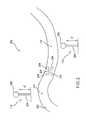
- FIG. 2is a schematic diagram illustrating the use of physical waypoint markers, in accordance with embodiments of the invention.
- FIG. 3is a schematic diagram illustrating methods for maintaining mine detection vehicles in formation, in accordance with embodiments of the invention.
- FIG. 4is a schematic diagram illustrating methods for maintaining mine detection vehicles in formation, showing error considerations, in accordance with embodiments of the invention.
- FIG. 5is a schematic diagram illustrating additional error considerations, in accordance with embodiments of the invention.
- FIG. 6is a block diagram illustrating remote controlled vehicles, in accordance with embodiments of the invention.
- Techniques of this disclosureallow one to reliably and accurately navigate remote controlled vehicles even when a GPS signal is lost (dropout occurs).
- Upon GPS dropoutone may utilize laser tracking along with compass navigation and/or wheel encoders. Additionally, one may utilize physical waypoint markers and/or an inertial navigation system to further aid in navigation. Using these techniques to achieve reliable and accurate navigation, remote controlled vehicles can be maintained in formation, such as a tight echelon formation useful in landmine clearing applications.
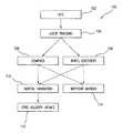
- FIG. 1illustrates representative embodiments for navigating remote controlled vehicles.
- methodology 100GPS navigation 102 , laser tracking navigation 104 , compass navigation 106 , wheel encoders 108 , inertial navigation 110 having zero velocity update functionality 112 , and physical waypoint markers 114 are used in combination.
- GPS navigation 102may be used initially to navigate one or more remote controlled vehicles.
- differential GPSDGPS
- DGPSdifferential GPS
- vehiclesmay be navigated to maintain a formation—a physical arrangement relative to one another.
- an echelon formationmay be employed. Such a formation is useful in several applications, including applications in which landmines are marked and/or cleared.
- the remote controlled vehiclesmay be mine detection vehicles (MDVs).
- GPS 102may experience dropout. In other words, for one or more reasons, one may lose the GPS signal, rendering GPS unusable temporarily or for an extended period of time. During GPS dropout, it is important to be able to maintain accurate navigation of the remote controlled vehicles. Accordingly, some backup system of navigation should be employed so that, for instance, the vehicles may maintain their formation and continue with their task.
- remote controlled vehiclesare navigated using a combination of laser tracking 104 along with one or both of compass navigation 106 and wheel encoders 108 .
- Switching to laser tracking 104 and one or more additional techniquesmay, in one embodiment, occur automatically upon realization that GPS 102 has dropped-out. In other embodiments, the switching to such systems may occur manually or through some other algorithm.
- Laser tracking 104may include any of a number of commercially-available or known laser tracking systems. As is known in the art, laser tracking systems provide for very accurate distance measurement, which may be used to guide navigation. To supply requisite angular information, one turns to compass navigation 106 and/or wheel encoders 108 .
- Compass navigation 106refers generally to any of a number of compass-based navigation systems commercially-available or known in the art to achieve navigation through magnetically-based measurement, or the like.
- wheel encoders 108refer generally to any of a number of wheel encoder systems commercially-available or known in the art to achieve navigation through the measurement of wheel rotations, or the like.
- compass navigation 106in combination with laser tracking 104 may achieve, in some situations, sufficient distance and angular control to satisfactorily navigate remote controlled vehicles even when GPS 102 has dropped-out. In other situations, sufficient distance and angular control may be achieved using wheel encoders 108 in combination with laser tracking 104 . In still other situations, one may wish to use compass navigation 106 , wheel encoders 108 , and laser tracking 104 all in combination. Using the three techniques together may be particularly suitable in situations in which a high degree of navigational accuracy is required—e.g., situations in which accuracy of 10 cm is required, which is typical in landmine applications.
- Elements 110 and 112 of FIG. 1illustrate that still additional navigational techniques may be utilized in combination with one or more of the other illustrated techniques, once GPS dropout occurs.
- an inertial navigation system 110may be used.
- Inertial navigation system 110refers to any of the systems commercially-available or known in the art that rely upon inertial measurements or ground speeds to navigate a vehicle.
- zero velocity update algorithm 112may be used in conjunction with inertial navigation system 110 to improve performance. Suitable zero velocity update techniques are disclosed in U.S. Pat. No. 6,292,751, which is incorporated by reference in its entirety.
- Physical waypoint marker 114is any physical marker that can be placed in a known position or at known coordinates and later detected by one or more vehicles so that those vehicles can correlate the marker with the known position. For instance, physical waypoint marker 114 may be placed upon a path at a known location, ascertained by GPS. Later, one or more vehicles may locate the marker and correlate the marker with the GPS position. In this way, the one or more vehicles may have an additional navigational reference point from which to navigate. Such a reference point may be particularly useful especially if GPS has dropped-out in the vicinity around the physical waypoint marker 114 .
- FIG. 2illustrates the use of physical waypoint markers in more detail.
- the arrows of FIG. 1do not necessarily connote a direction of events. Rather, the arrows of FIG. 1 are meant simply to show that upon GPS 102 dropout, control may be shifted to laser tracking 104 and compass navigation 106 and/or wheel encoders 108 . In addition to compass navigation 106 and/or wheel encoders 108 , additional techniques such as inertial navigation system 110 and/or physical waypoint marker 114 may be used, upon GPS 102 dropout.
- FIG. 2shows methodology 200 for using physical waypoint markers 114 .
- a path 202two physical waypoint markers 114 , and five remote controlled vehicles 204 .
- physical waypoint markers 114may be placed in known positions along path 202 .
- the positions of the physical waypoint markersmay be known through the use of GPS or any other navigational technique. If the physical waypoint markers 114 are known through GPS, the markers themselves may be called GPS physical waypoint markers.
- the physical waypoint markers 114may include a support member 206 and a detection member 208 .
- the support member 206may extend about 6 inches from the ground, although this is representative only and not limiting.
- detection member 208The purpose of detection member 208 is to allow remote controlled vehicles 204 to detect the physical waypoint marker 114 .
- the designmay vary greatly and may be any shape or material to increase its probability of being detected by vehicles 204 .
- remote controlled vehicles 204may detect the physical waypoint markers 114 through the use of machine vision, by detecting a reflection from detection member 208 , or the like. Relaying the GPS coordinates or position information associated with physical waypoint marker 114 to one or more of the vehicles 204 may be done via radio transmission, IR transmission, or any other wireless communication technique.
- FIG. 3there is shown a formation 300 of remote controlled vehicles 204 , which are, in this illustration, mine detection vehicles (MDVs).
- MDVsmine detection vehicles
- FIG. 3the vehicles are being maintained in an echelon formation, although it will be understood by those of ordinary skill in the art that any other type of formation requiring navigational control may be maintained as well.
- Vehicle 204 ais the lead MDV, while vehicles 204 b and 204 c are following MDVs (MDVs # 2 and # 3 respectively).
- MDVs # 2 and # 3MDVs
- Each MDVis equipped with laser tracking equipment 302 , which may include a laser and/or reflectors.
- Also included on one or more of MDVs 204are a GPS system (not shown), a compass navigation system 106 (not shown), wheel encoders 108 (not shown), inertial navigation system 110 (not shown), and/or a physical waypoint marker detection system 114 (not shown).
- the different vehicles 204 of FIG. 3may experience GPS dropout at different times. In that case, the vehicles 204 experiencing dropout may switch to a combination of laser tracking 104 using laser tracking equipment 302 in combination with compass navigation 106 and/or wheel encoders 108 . Additionally, the vehicles 204 may utilize inertial navigation 110 (with or without zero velocity update techniques 112 ) and/or physical waypoint markers 114 . The vehicles that have not experienced GPS dropout may continue to use GPS to, for instance, re-establish or maintain a tight formation.
- the vehicles 204 of FIG. 3are able to maintain a formation, such as the tight echelon formation illustrated. This ability assists in, for instance, the effective clearing and marking of landmines.
- FIGS. 4 and 5illustrate representative error considerations for embodiments of the present disclosure.
- the positional error associated between vehicle 204 a and 204 bis ⁇ 10 cm.
- the same erroris associated between vehicle 204 a and 204 c .
- the relative erroris ⁇ 20 cm since this error includes error between 204 a and 204 b as well as error between 204 a and 204 c .
- These values for errorare not limiting; they are included to illustrate, among other things, how error may propagate between and among vehicles in formation. Nevertheless, even in view of error propagation, very accurate navigation can still be achieved ( ⁇ 10 or 20 cm in the illustrated embodiment) using the techniques of this disclosure.
- FIG. 5is related to FIG. 4 in that it further illustrates the error issues of FIG. 4 .
- error probability distributions and positional uncertainty plotsare presented. Again, the values for these errors are not limiting and are included to illustrate a representative embodiment.
- FIG. 6illustrates a remote controlled vehicle 204 equipped to perform the navigational techniques of this disclosure.
- the vehicle 204includes systems for utilizing the techniques illustrated and described in relation to FIG. 1 .
- the arrows of FIG. 6do not necessarily connote a direction of events. Rather, the arrows of FIG. 6 are meant simply to show what component systems are included with (or coupled to or in operative relation with) vehicle 204 .
- the remote controlled aspect of vehicles 204offers many advantages. For instance, in the context of landmine detection vehicles, techniques of this disclosure may allow an operator to remotely control up to three mine detection vehicles in order to sweep a pathway of eight meters maximum width. The techniques provide the capability to establish and maintain echelon formation with the required accuracy to undergo landmine clearing and other landmine applications.
- the remote controlled vehiclesmay provide (a) video feedback to the operator for control over extended distances, (b) vehicle status information, (c) and all control actuators necessary to accomplish the mission.
- the navigational techniques of this disclosureoffer many advantages as well, including advantages for landmine applications. They provide a means to determine a vehicle's location, either absolute or relative, within (in one embodiment) 10 cm. If the principal navigation method is GPS-based, techniques of this disclosure provide a backup method for mission execution when GPS is unavailable (dropout).
- GPS navigation system 102offers important navigation capabilities. GPS may utilize one or both of at least two possible error corrected configurations.
- RTKReal Time Kinematic
- DGPSdifferential GPS
- error correctionimproves basic GPS accuracy, but error correction must typically be provided by a “base station.”
- the base stationis typically located at a precisely known position for absolute accuracy. If the base station location is not accurately known, high accuracy relative to the base station's location is, however, still achievable (high accuracy relative to base station's position, but not in absolute terms). Accuracy of 1 to 3 cm is achievable, either absolute or relative.
- GPStypically requires receiver access to five GPS satellites, and receiver hardware is mature and readily-available commercially.
- Wide Area Augmentation System (WAAS) implementationis likely to replace base station need in the future, which may be beneficial given that the base station must typically be moved forward after each 10 km landmine distance is cleared, presenting logistical and tactical problems.
- WAASWide Area Augmentation System
- error-correction signalsare available via commercial navigation systems, which utilize both GPS and supplemental error-correcting systems. These systems require receiver access to four GPS satellites, one geo-stationary satellite. Error corrections are typically transmitted from geo-stationary commercial satcom systems (INMARSAT, INTELSAT, etc). These systems eliminate the requirement for a stationary earth base station and are still capable of meeting 10 cm accuracy requirement important for high-accuracy applications such as landmine marking and clearing. Hardware for these systems is mature and readily-available commercially.
- Laser positioning systemsuch as laser tracking system 104 may include laser rangefinder equipment that allows distance measurement to within centimeter accuracy.
- a known distance and reference angleallows accurate location of items of interest within a polar coordinate system referenced to the laser tracker, which provides a means for maintaining relative positioning of remote controlled vehicles such as MDVs within satisfactory accuracy ranges (e.g., 10 cm) even without GPS availability.
- remote controlled vehiclessuch as MDVs within satisfactory accuracy ranges (e.g., 10 cm) even without GPS availability.
- MDVsremote controlled vehicles
- Switchover to laser tracking systemmay require re-establishing a tight echelon formation. GPS operation may allow a formation to extend or stretch out, and laser tracking may maintain a tight formation once re-established.
- a stationary satellite-based DGPS systemmeets all requirements for vehicle navigation typical in landmine applications, readily meeting a 10 cm accuracy requirement and involving well understood, mature technology that eliminates on-site base station requirement.
- Laser trackingalso meets all requirements for landmine vehicle navigation and allows continued operation after GPS dropout.
- Laser tracking along with compass navigation and/or wheel encodersmay be used to maintain echelon formation of MDVs, and physical mine marking may be performed by MDVs during laser positioning.
- Real time velocity information from MDV wheel encoders and on-board fluxgate compassmay allow accurate mine location marking. Secondary vehicles may access mine locations visually.
- GPS dropout conditionsmay occur because of moving into an area with terrain or canopy blockage.
- MDV # 1 204 aas lead vehicle, may be assumed to encounter dropout first.
- MDVs 2 and 3( 204 b and 204 c ) are expected to be able to proceed to the point of dropout for MDV # 1 204 a.
- MDVs # 2 and 3may proceed, under GPS, to reestablish a tight echelon formation. MDVs may proceed using a laser tracking positioning system to maintain formation, aided by compass and wheel encoder speed information.
- manual positioning of MDVs # 1 and 2 relative to 3may be performed to reestablish tight echelon formation in the case of concurrent GPS loss by all three vehicles. Mines may be marked physically while operating in GPS dropout conditions.
- the remote control systemshall allow remote control of MDVs at all speeds up to 10 kph in mission execution mode.
- An administrative movement modeshall allow remote control of the vehicles at all speeds up to 40 kph.
- the remote control systemshall provide for safe and effective remote operation of the vehicles.
- a maximum of three remote control systemsshall be capable of simultaneous operation to support echelon movement of MDVs and up to three control vehicles.
- the systemshall be capable of maintaining five meter minimum separation among MDVs, and 25 meter minimum separation from MDVs to control vehicles.
- the systemshall be capable of controlling vehicles at non-line-of-sight distances of at least 300 meters.
- the systemshall provide fail-safe features to minimize hazards from any failed tele-operation of the system.
- MDV # 1may be lead vehicle, occupying either an outside position (left or right selectable in mission software). MDV # 1 may be operated (manually driven) via tele-operation by an MDV operator, using video feedback and joystick control. MDV # 1 , via onboard GPS, may generate a series of electronic waypoints along its manually driven path. Offset electronic waypoints, based on the desired echelon formation, may be calculated and passed to MDVs 2 and 3 . MDVs 2 and 3 may operate in semi-autonomous mode as they self-navigate along the provided sets of electronic waypoints.
- the second GPS based tele-op modemay be available when accurate, digital maps of the mission area are available for download and utilization.
- a mission planning operatormay designate a series of electronic GPS waypoints on the digital map that will become the path for MDV # 1 .
- MDV # 1may proceed along the designated waypoint path in semi-autonomous mode.
- offset electronic waypointsmay be calculated for MDVs 2 and 3 as in the previous GPS based mode of operation.
- MDVs 2 and 3may function in the same fashion as in the previous GPS based mode of operation.
- An MDV operator's functionmay become primarily oversight: watching for obstacles, lane width changes, vehicle status, etc.
- MDV # 1may be manually controlled as in the primary mode.
- MDVs 2 and 3may be maintained in echelon formation through the use of a laser tracking system, augmented with compass heading and wheel speed information provided from each vehicle. Mine locations may be marked physically for visual access by follow-on vehicles.
- an operator's displaymay include a conventional 2-D flat panel display coupled to single video camera, manually steered.
- a multi-function joystick controlmay be included.
- Up to 256 vehicle control/actuator channelsmay be present.
- Video and data linksmay be made via wireless Ethernet LAN in RS-232 format.
- Vehiclesmay be individually addressable for manual steering.
- Echelon formationmay utilize MDV # 1 position with offset electronic waypoints for MDVs 2 and 3 .
- MDV # 1can occupy either left-most or right-most lead position.
- Eight-meter, 6-meter, and 4-meter echelon width optionsmay be be quickly selectable, and support may be provided for pathway width variation.
Landscapes
- Engineering & Computer Science (AREA)
- Radar, Positioning & Navigation (AREA)
- Remote Sensing (AREA)
- Physics & Mathematics (AREA)
- Automation & Control Theory (AREA)
- General Physics & Mathematics (AREA)
- Aviation & Aerospace Engineering (AREA)
- Electromagnetism (AREA)
- Optics & Photonics (AREA)
- Position Fixing By Use Of Radio Waves (AREA)
- Navigation (AREA)
- Traffic Control Systems (AREA)
Abstract
Description
- U.S. Pat. No. 6,292,751
- U.S. Pat. No. 6,122,572
- U.S. Pat. No. 5,890,091
- U.S. Pat. No. 6,411,871
- U.S. Pat. No. 6,072,433
- U.S. Pat. No. 5,307,272
- U.S. Pat. No. 6,333,631
- U.S. Pat. No. 5,684,696
Claims (24)
Priority Applications (1)
| Application Number | Priority Date | Filing Date | Title |
|---|---|---|---|
| US10/274,839US6859729B2 (en) | 2002-10-21 | 2002-10-21 | Navigation of remote controlled vehicles |
Applications Claiming Priority (1)
| Application Number | Priority Date | Filing Date | Title |
|---|---|---|---|
| US10/274,839US6859729B2 (en) | 2002-10-21 | 2002-10-21 | Navigation of remote controlled vehicles |
Publications (2)
| Publication Number | Publication Date |
|---|---|
| US20040078137A1 US20040078137A1 (en) | 2004-04-22 |
| US6859729B2true US6859729B2 (en) | 2005-02-22 |
Family
ID=32093159
Family Applications (1)
| Application Number | Title | Priority Date | Filing Date |
|---|---|---|---|
| US10/274,839Expired - LifetimeUS6859729B2 (en) | 2002-10-21 | 2002-10-21 | Navigation of remote controlled vehicles |
Country Status (1)
| Country | Link |
|---|---|
| US (1) | US6859729B2 (en) |
Cited By (52)
| Publication number | Priority date | Publication date | Assignee | Title |
|---|---|---|---|---|
| US20050159852A1 (en)* | 2004-01-20 | 2005-07-21 | Rheinmetall Landsysteme Gmbh | Arrangement of a first and at least a second additional vehicle in a loosely couplable not track bound train |
| US20050192721A1 (en)* | 2004-02-27 | 2005-09-01 | Jouppi Norman P. | Mobile device control system |
| US20050246078A1 (en)* | 2004-04-30 | 2005-11-03 | Jan Vercammen | Automatically guided vehicle with improved navigation |
| US20060190165A1 (en)* | 2003-07-03 | 2006-08-24 | Hannu Makela | Method and system for monitoring location of mining vehicle |
| US20070061053A1 (en)* | 2005-09-13 | 2007-03-15 | Deere & Company, A Delaware Corporation. | Method and system for modular data processing for a vehicle control system |
| US20070069083A1 (en)* | 2005-06-20 | 2007-03-29 | United States Of America As Represented By The Administrator Of The National Aeronautics And Spac | Self-Contained Avionics Sensing And Flight Control System For Small Unmanned Aerial Vehicle |
| US20080243317A1 (en)* | 2004-06-08 | 2008-10-02 | Maria Jesus Morales De La Rica | System And Method For Controlling An Unarmed Air Vehicle |
| US20080262718A1 (en)* | 2007-04-17 | 2008-10-23 | Itt Manufacturing Enterprises, Inc. | Landmark Navigation for Vehicles Using Blinking Optical Beacons |
| US20080284668A1 (en)* | 2007-05-15 | 2008-11-20 | Toyota Engineering & Manufacturing North America, Inc. | Gradient index lens for microwave radiation |
| US7543780B1 (en) | 2004-10-04 | 2009-06-09 | The United States Of America As Represented By The Secretary Of The Air Force | Unmanned air vehicle transmission line docking surveillance |
| US20090222160A1 (en)* | 2008-03-03 | 2009-09-03 | Cnh America Llc | Method and system for coordinated vehicle control with wireless communication |
| US20100049376A1 (en)* | 2008-08-19 | 2010-02-25 | Abraham Schultz | Method and system for providing a gps-based position |
| US20100063680A1 (en)* | 2008-09-11 | 2010-03-11 | Jonathan Louis Tolstedt | Leader-follower semi-autonomous vehicle with operator on side |
| US20100063954A1 (en)* | 2008-09-11 | 2010-03-11 | Noel Wayne Anderson | Distributed knowledge base method for vehicular localization and work-site management |
| US20100063652A1 (en)* | 2008-09-11 | 2010-03-11 | Noel Wayne Anderson | Garment for Use Near Autonomous Machines |
| US20100063651A1 (en)* | 2008-09-11 | 2010-03-11 | Noel Wayne Anderson | High integrity perception for machine localization and safeguarding |
| US20100274434A1 (en)* | 2009-04-28 | 2010-10-28 | Caterpillar Inc. | Position monitoring system for a mobile machine |
| US7845560B2 (en) | 2004-12-14 | 2010-12-07 | Sky-Trax Incorporated | Method and apparatus for determining position and rotational orientation of an object |
| US20110010023A1 (en)* | 2005-12-03 | 2011-01-13 | Kunzig Robert S | Method and apparatus for managing and controlling manned and automated utility vehicles |
| US20110039573A1 (en)* | 2009-08-13 | 2011-02-17 | Qualcomm Incorporated | Accessing positional information for a mobile station using a data code label |
| US20110178708A1 (en)* | 2010-01-18 | 2011-07-21 | Qualcomm Incorporated | Using object to align and calibrate inertial navigation system |
| US20120197519A1 (en)* | 2011-01-31 | 2012-08-02 | James Joseph Richardson | Coded marker navigation system and method |
| US8327748B2 (en) | 2007-11-26 | 2012-12-11 | Vincent Paul Conroy | Robotic defilade system |
| US8467928B2 (en) | 2008-09-11 | 2013-06-18 | Deere & Company | Multi-vehicle high integrity perception |
| US20130211658A1 (en)* | 2012-02-10 | 2013-08-15 | Deare & Company | Method and stereo vision system for facilitating the unloading of agricultural material from a vehicle |
| US8513580B1 (en)* | 2012-06-26 | 2013-08-20 | The United States Of America As Represented By The Secretary Of The Navy | Targeting augmentation for short-range munitions |
| US20130245878A1 (en)* | 2002-11-12 | 2013-09-19 | Steffen Armbruster | Method and system for transporting material |
| US8560145B2 (en) | 2008-09-11 | 2013-10-15 | Deere & Company | Distributed knowledge base program for vehicular localization and work-site management |
| US20140060949A1 (en)* | 2012-08-31 | 2014-03-06 | Autonomous Tractor Corporation | Navigation system and method |
| US8700324B2 (en) | 2010-08-25 | 2014-04-15 | Caterpillar Inc. | Machine navigation system having integrity checking |
| US8948446B2 (en) | 2011-01-19 | 2015-02-03 | Honeywell International Inc. | Vision based zero velocity and zero attitude rate update |
| US8989972B2 (en) | 2008-09-11 | 2015-03-24 | Deere & Company | Leader-follower fully-autonomous vehicle with operator on side |
| US9026315B2 (en) | 2010-10-13 | 2015-05-05 | Deere & Company | Apparatus for machine coordination which maintains line-of-site contact |
| US9188980B2 (en) | 2008-09-11 | 2015-11-17 | Deere & Company | Vehicle with high integrity perception system |
| US9229089B2 (en) | 2010-06-10 | 2016-01-05 | Qualcomm Incorporated | Acquisition of navigation assistance information for a mobile station |
| US9296411B2 (en) | 2014-08-26 | 2016-03-29 | Cnh Industrial America Llc | Method and system for controlling a vehicle to a moving point |
| US9534898B2 (en)* | 2010-06-16 | 2017-01-03 | Topcon Positioning Systems, Inc. | Method and apparatus for determining direction of the beginning of vehicle movement |
| CN106382897A (en)* | 2016-11-14 | 2017-02-08 | 长沙职业技术学院 | Measuring and control system for positioning parameter of intelligent automotive independent suspended front wheel |
| US9922282B2 (en) | 2015-07-21 | 2018-03-20 | Limitless Computing, Inc. | Automated readiness evaluation system (ARES) for use with an unmanned aircraft system (UAS) |
| CN108353246A (en)* | 2015-10-29 | 2018-07-31 | 华为技术有限公司 | Localization method, server, base station, mobile terminal in mobile network and system |
| US10635758B2 (en) | 2016-07-15 | 2020-04-28 | Fastbrick Ip Pty Ltd | Brick/block laying machine incorporated in a vehicle |
| US10865578B2 (en) | 2016-07-15 | 2020-12-15 | Fastbrick Ip Pty Ltd | Boom for material transport |
| US11051185B2 (en)* | 2017-11-16 | 2021-06-29 | Telefonaktiebolaget Lm Ericsson (Publ) | Configuration for flight status indication of an aerial UE |
| US11401115B2 (en) | 2017-10-11 | 2022-08-02 | Fastbrick Ip Pty Ltd | Machine for conveying objects and multi-bay carousel for use therewith |
| US11441899B2 (en) | 2017-07-05 | 2022-09-13 | Fastbrick Ip Pty Ltd | Real time position and orientation tracker |
| US11656357B2 (en) | 2017-08-17 | 2023-05-23 | Fastbrick Ip Pty Ltd | Laser tracker with improved roll angle measurement |
| US11958193B2 (en) | 2017-08-17 | 2024-04-16 | Fastbrick Ip Pty Ltd | Communication system for an interaction system |
| US12214500B2 (en) | 2018-07-16 | 2025-02-04 | Fastbrick Ip Pty Ltd | Backup tracking for an interaction system |
| US12242916B2 (en) | 2017-11-17 | 2025-03-04 | Divine Logic, Inc. | Systems and methods for tracking items |
| US12311546B2 (en) | 2018-07-16 | 2025-05-27 | Fastbrick Ip Pty Ltd | Active damping system |
| US12385265B2 (en) | 2020-04-22 | 2025-08-12 | Fastbrick Ip Pty Ltd | Block transfer apparatus and improved clamping assembly for use therewith |
| US12398574B2 (en) | 2020-07-08 | 2025-08-26 | Fastbrick Ip Pty Ltd | Adhesive application system |
Families Citing this family (22)
| Publication number | Priority date | Publication date | Assignee | Title |
|---|---|---|---|---|
| JP2005256469A (en)* | 2004-03-12 | 2005-09-22 | Hitachi Constr Mach Co Ltd | Setting/control system of execution work area |
| EP1677125A1 (en)* | 2004-12-28 | 2006-07-05 | Leica Geosystems AG | Method and rotative laser for determining a positional information of at least one object |
| US7236861B2 (en) | 2005-02-16 | 2007-06-26 | Lockheed Martin Corporation | Mission planning system with asynchronous request capability |
| JP2009521630A (en)* | 2005-12-30 | 2009-06-04 | ゴールドウィング ノミニーズ ピーティーワイ リミテッド | Automatic brick laying system for building buildings with multiple bricks |
| US8089390B2 (en)* | 2006-05-16 | 2012-01-03 | Underground Imaging Technologies, Inc. | Sensor cart positioning system and method |
| US8015547B2 (en)* | 2006-06-29 | 2011-09-06 | Augusta Systems, Inc. | Reconfigurable, hierarchical component-based architecture and framework and methods for rapidly developing sensor device-enabling software applications |
| US8095923B2 (en)* | 2006-06-29 | 2012-01-10 | Augusta Systems, Inc. | System and method for deploying and managing intelligent nodes in a distributed network |
| US20080005721A1 (en)* | 2006-06-29 | 2008-01-03 | Augusta Systems, Inc. | Method and System for Rapidly Developing Sensor-Enabled Software Applications |
| US7735060B2 (en)* | 2006-06-29 | 2010-06-08 | Augusta Systems, Inc. | Method and system for rapidly developing and deploying sensor-enabled software applications |
| FR2918185A1 (en)* | 2007-06-26 | 2009-01-02 | Bouygues Construction Sa | Tool carrying robot guiding method for drilling e.g. roof lining, wall in tunnel, involves placing markers in environment in which robot is moved, where robot is moved towards its support points while being located with respect to markers |
| AU2008291702A1 (en)* | 2007-08-28 | 2009-03-05 | Goldwing Nominees Pty Ltd | System and method for precise real-time measurement of a target position and orientation relative to a base position, and control thereof |
| FR2931451B1 (en)* | 2008-05-22 | 2010-12-17 | Fmc Technologies Sa | CONTROL DEVICE FOR SYSTEM FOR LOADING AND / OR UNLOADING FLUIDS |
| US8478493B2 (en)* | 2008-09-11 | 2013-07-02 | Deere & Company | High integrity perception program |
| ITMI20102192A1 (en)* | 2010-11-26 | 2012-05-27 | Francesco Fava | SELF-PROPELLED MOTORIZED DEVICE WITH TRACKING AND / OR PRECESSION CAPACITY, PARTICULARLY FOR OBJECTS EQUIPPED WITH WHEELS AND / OR TRACKS, TROLLEYS AND MEANS OF TRANSPORT IN GENERAL. |
| US9341720B2 (en) | 2011-01-11 | 2016-05-17 | Qualcomm Incorporated | Camera-based position location and navigation based on image processing |
| CN102353379B (en)* | 2011-07-06 | 2013-02-13 | 上海海事大学 | Environment modeling method applicable to navigation of automatic piloting vehicles |
| US10078336B2 (en) | 2013-12-19 | 2018-09-18 | Husqvarna Ab | System and method for navigating a robotic working tool |
| DE102014210147A1 (en)* | 2014-05-27 | 2015-12-03 | Continental Teves Ag & Co. Ohg | Vehicle control system for autonomous guidance of a vehicle |
| JP6353322B2 (en)* | 2014-09-04 | 2018-07-04 | 日立建機株式会社 | Transport vehicle and travel control device thereof |
| US9650039B2 (en)* | 2015-03-20 | 2017-05-16 | Ford Global Technologies, Llc | Vehicle location accuracy |
| US11550052B2 (en)* | 2018-10-17 | 2023-01-10 | United States Of America, As Represented By The Secretary Of The Army | Interferometric synthetic aperture acoustic imager |
| GB2599159A (en)* | 2020-09-28 | 2022-03-30 | Mastercard International Inc | Location determination |
Citations (10)
| Publication number | Priority date | Publication date | Assignee | Title |
|---|---|---|---|---|
| US4445706A (en)* | 1982-03-11 | 1984-05-01 | Jarosek James P | Tandem hitch apparatus |
| US5307272A (en) | 1991-08-19 | 1994-04-26 | The United States Of America As Represented By The United States Department Of Energy | Minefield reconnaissance and detector system |
| US5646843A (en)* | 1990-02-05 | 1997-07-08 | Caterpillar Inc. | Apparatus and method for surface based vehicle control system |
| US5757646A (en)* | 1994-02-18 | 1998-05-26 | Trimble Navigation Limited | Centimeter accurate global positioning system receiver for on-the-fly real-time kinematic measurement and control |
| US6072433A (en) | 1996-07-31 | 2000-06-06 | California Institute Of Technology | Autonomous formation flying sensor |
| US6122572A (en) | 1995-05-08 | 2000-09-19 | State Of Israel | Autonomous command and control unit for mobile platform |
| US6292751B1 (en)* | 2000-02-08 | 2001-09-18 | Bae Systems | Positioning refinement algorithm |
| US6333631B1 (en) | 1999-03-08 | 2001-12-25 | Minister Of National Defence Of Her Majesty's Canadian Government | Cantilevered manipulator for autonomous non-contact scanning of natural surfaces for the deployment of landmine detectors |
| US20020035419A1 (en) | 2000-08-05 | 2002-03-21 | Ching-Fang Lin | Autonomous navigation, guidance and control using LDRI |
| US6560535B2 (en)* | 2000-01-05 | 2003-05-06 | The Johns Hopkins University | Global positioning system roadside integrated precision positioning system |
- 2002
- 2002-10-21USUS10/274,839patent/US6859729B2/ennot_activeExpired - Lifetime
Patent Citations (13)
| Publication number | Priority date | Publication date | Assignee | Title |
|---|---|---|---|---|
| US4445706A (en)* | 1982-03-11 | 1984-05-01 | Jarosek James P | Tandem hitch apparatus |
| US5646843A (en)* | 1990-02-05 | 1997-07-08 | Caterpillar Inc. | Apparatus and method for surface based vehicle control system |
| US5684696A (en) | 1990-02-05 | 1997-11-04 | Caterpillar Inc. | System and method for enabling an autonomous vehicle to track a desired path |
| US5307272A (en) | 1991-08-19 | 1994-04-26 | The United States Of America As Represented By The United States Department Of Energy | Minefield reconnaissance and detector system |
| US5757646A (en)* | 1994-02-18 | 1998-05-26 | Trimble Navigation Limited | Centimeter accurate global positioning system receiver for on-the-fly real-time kinematic measurement and control |
| US5890091A (en) | 1994-02-18 | 1999-03-30 | Trimble Navigation Ltd. | Centimeter accurate global positioning system receiver for on-the-fly real-time kinematic measurement and control |
| US6122572A (en) | 1995-05-08 | 2000-09-19 | State Of Israel | Autonomous command and control unit for mobile platform |
| US6072433A (en) | 1996-07-31 | 2000-06-06 | California Institute Of Technology | Autonomous formation flying sensor |
| US6333631B1 (en) | 1999-03-08 | 2001-12-25 | Minister Of National Defence Of Her Majesty's Canadian Government | Cantilevered manipulator for autonomous non-contact scanning of natural surfaces for the deployment of landmine detectors |
| US6560535B2 (en)* | 2000-01-05 | 2003-05-06 | The Johns Hopkins University | Global positioning system roadside integrated precision positioning system |
| US6292751B1 (en)* | 2000-02-08 | 2001-09-18 | Bae Systems | Positioning refinement algorithm |
| US20020035419A1 (en) | 2000-08-05 | 2002-03-21 | Ching-Fang Lin | Autonomous navigation, guidance and control using LDRI |
| US6411871B1 (en) | 2000-08-05 | 2002-06-25 | American Gnc Corporation | Autonomous navigation, guidance and control using LDRI |
Non-Patent Citations (11)
| Title |
|---|
| "Formation alignment of multiple autonomous vehicles," NASA's Jet Propulsion Laboratory, Oct. 2002, 3 pages from http://www.nasatech.com/Briefs/Oct02/NPO20599.html. |
| "MECH1810 Computational Engng. 1B (Revised), Assignment 3-Estimating Mobile Robot Position," Australian Center for Field Robotics (ACFR), the University of Sydney. 11 pages printed from the ACFR website://www.acfr.usyd.edu.au/teaching/1st-year/mech1810/material/assignments/ . . . ass3.htm, on Oct. 4, 2002. |
| FanBeam4-Laser Radar Positioning System description, Measurement Devices, Ltd. Company, Scotland, Sep. 19, 2001, from www.mdl.co.uk/marine/fanbeam4.htm. |
| FanBeam4-Seismic Software, Precision Positioning and Tracking Software for Fanbeam, Measurement Devices, Ltd. Company, Scotland, Jul. 7, 2001, from www.mdl.co.uk/marine/seismicsw.htm. |
| FanBeam4-Single Target DP Software, Precision Dynamic Positioning Control Software for Fanbeam, Measurement Devices, Ltd. Company, Scotland, Jul. 4, 2001, from www.mdl.co.uk/marine/singletargetsw.htm. |
| FanBeam4-Technical Specifications, Measurement Devices, Ltd. Company, Scotland, Jul. 4, 2001, from www.mdl.co.uk/marine/fanbeam4t.htm. |
| Farwell et al., "RTK-based vehicle tracking and unmanned operation for agriculture," ION GPS-99 12<th >International Technical Meeting of the Satellite Division of the Institute of Navigation, Sep. 14-17, 1999, Session A6, pp. 2047-2054, 1999. |
| Joint Robotics Program Master Plan, 2001. |
| Joint Robotics Program Master Plan, 2002. |
| Web page relating to "agv and positioning applications," 1 page from http://www.gcsltd.co.uk/body_applications.html, Guidance Control Systems, Ltd., 2002, printed on Oct. 4, 2002. |
| Web pages relating to "The Robot Channel-Sensor Lab Kits," 2 pages from http://www.smartrobots.com/sensor_lab_kits.htm, Aug. 1, 2002, printed on Oct. 4, 2002. |
Cited By (95)
| Publication number | Priority date | Publication date | Assignee | Title |
|---|---|---|---|---|
| US20130245878A1 (en)* | 2002-11-12 | 2013-09-19 | Steffen Armbruster | Method and system for transporting material |
| US20060190165A1 (en)* | 2003-07-03 | 2006-08-24 | Hannu Makela | Method and system for monitoring location of mining vehicle |
| US7853402B2 (en)* | 2003-07-03 | 2010-12-14 | Sandvik Mining And Construction Oy | Monitoring location of mining vehicle using base stations in at least two sections of mine |
| US20050159852A1 (en)* | 2004-01-20 | 2005-07-21 | Rheinmetall Landsysteme Gmbh | Arrangement of a first and at least a second additional vehicle in a loosely couplable not track bound train |
| US7859566B2 (en)* | 2004-01-20 | 2010-12-28 | Rheinmetall Landsysteme Gmbh | Arrangement of a first and at least a second additional vehicle in a loosely couplable not track bound train |
| US20050192721A1 (en)* | 2004-02-27 | 2005-09-01 | Jouppi Norman P. | Mobile device control system |
| US7756614B2 (en)* | 2004-02-27 | 2010-07-13 | Hewlett-Packard Development Company, L.P. | Mobile device control system |
| US20050246078A1 (en)* | 2004-04-30 | 2005-11-03 | Jan Vercammen | Automatically guided vehicle with improved navigation |
| US20080243317A1 (en)* | 2004-06-08 | 2008-10-02 | Maria Jesus Morales De La Rica | System And Method For Controlling An Unarmed Air Vehicle |
| US8285425B2 (en)* | 2004-06-08 | 2012-10-09 | Instituto Nacional De Tecnica Aeroespacial “Esteban Terradas” | System and method for controlling an unarmed air vehicle |
| US7543780B1 (en) | 2004-10-04 | 2009-06-09 | The United States Of America As Represented By The Secretary Of The Air Force | Unmanned air vehicle transmission line docking surveillance |
| US20110121068A1 (en)* | 2004-12-14 | 2011-05-26 | Sky-Trax, Inc. | Method and apparatus for determining position and rotational orientation of an object |
| US7845560B2 (en) | 2004-12-14 | 2010-12-07 | Sky-Trax Incorporated | Method and apparatus for determining position and rotational orientation of an object |
| US8196835B2 (en) | 2004-12-14 | 2012-06-12 | Sky-Trax, Inc. | Method and apparatus for determining position and rotational orientation of an object |
| US20070069083A1 (en)* | 2005-06-20 | 2007-03-29 | United States Of America As Represented By The Administrator Of The National Aeronautics And Spac | Self-Contained Avionics Sensing And Flight Control System For Small Unmanned Aerial Vehicle |
| US7962252B2 (en) | 2005-06-20 | 2011-06-14 | The United States Of America As Represented By The Administrator Of The National Aeronautics And Space Administration | Self-contained avionics sensing and flight control system for small unmanned aerial vehicle |
| US7844396B2 (en)* | 2005-09-13 | 2010-11-30 | Deere & Company | Method and system for modular data processing for a vehicle control system |
| US20070061053A1 (en)* | 2005-09-13 | 2007-03-15 | Deere & Company, A Delaware Corporation. | Method and system for modular data processing for a vehicle control system |
| US8381982B2 (en) | 2005-12-03 | 2013-02-26 | Sky-Trax, Inc. | Method and apparatus for managing and controlling manned and automated utility vehicles |
| US20110010023A1 (en)* | 2005-12-03 | 2011-01-13 | Kunzig Robert S | Method and apparatus for managing and controlling manned and automated utility vehicles |
| US7739034B2 (en) | 2007-04-17 | 2010-06-15 | Itt Manufacturing Enterprises, Inc. | Landmark navigation for vehicles using blinking optical beacons |
| US20080262718A1 (en)* | 2007-04-17 | 2008-10-23 | Itt Manufacturing Enterprises, Inc. | Landmark Navigation for Vehicles Using Blinking Optical Beacons |
| US20080284668A1 (en)* | 2007-05-15 | 2008-11-20 | Toyota Engineering & Manufacturing North America, Inc. | Gradient index lens for microwave radiation |
| US8327748B2 (en) | 2007-11-26 | 2012-12-11 | Vincent Paul Conroy | Robotic defilade system |
| US8160765B2 (en)* | 2008-03-03 | 2012-04-17 | Cnh America Llc | Method and system for coordinated vehicle control with wireless communication |
| US20090222160A1 (en)* | 2008-03-03 | 2009-09-03 | Cnh America Llc | Method and system for coordinated vehicle control with wireless communication |
| US8306727B2 (en)* | 2008-03-03 | 2012-11-06 | Cnh America Llc | Method and system for coordinated vehicle control with wireless communication |
| US20120095620A1 (en)* | 2008-03-03 | 2012-04-19 | Morselli Riccardo | Method and System for Coordinated Vehicle Control with Wireless Communication |
| US20100049376A1 (en)* | 2008-08-19 | 2010-02-25 | Abraham Schultz | Method and system for providing a gps-based position |
| US8165728B2 (en)* | 2008-08-19 | 2012-04-24 | The United States Of America As Represented By The Secretary Of The Navy | Method and system for providing a GPS-based position |
| US8666587B2 (en) | 2008-09-11 | 2014-03-04 | Deere & Company | Multi-vehicle high integrity perception |
| US9274524B2 (en) | 2008-09-11 | 2016-03-01 | Deere & Company | Method for machine coordination which maintains line-of-site contact |
| US9188980B2 (en) | 2008-09-11 | 2015-11-17 | Deere & Company | Vehicle with high integrity perception system |
| US20100063954A1 (en)* | 2008-09-11 | 2010-03-11 | Noel Wayne Anderson | Distributed knowledge base method for vehicular localization and work-site management |
| US8818567B2 (en) | 2008-09-11 | 2014-08-26 | Deere & Company | High integrity perception for machine localization and safeguarding |
| US20100063651A1 (en)* | 2008-09-11 | 2010-03-11 | Noel Wayne Anderson | High integrity perception for machine localization and safeguarding |
| US8989972B2 (en) | 2008-09-11 | 2015-03-24 | Deere & Company | Leader-follower fully-autonomous vehicle with operator on side |
| US20100063680A1 (en)* | 2008-09-11 | 2010-03-11 | Jonathan Louis Tolstedt | Leader-follower semi-autonomous vehicle with operator on side |
| US8392065B2 (en) | 2008-09-11 | 2013-03-05 | Deere & Company | Leader-follower semi-autonomous vehicle with operator on side |
| US8467928B2 (en) | 2008-09-11 | 2013-06-18 | Deere & Company | Multi-vehicle high integrity perception |
| US20100063652A1 (en)* | 2008-09-11 | 2010-03-11 | Noel Wayne Anderson | Garment for Use Near Autonomous Machines |
| US9235214B2 (en) | 2008-09-11 | 2016-01-12 | Deere & Company | Distributed knowledge base method for vehicular localization and work-site management |
| US8560145B2 (en) | 2008-09-11 | 2013-10-15 | Deere & Company | Distributed knowledge base program for vehicular localization and work-site management |
| US20100274434A1 (en)* | 2009-04-28 | 2010-10-28 | Caterpillar Inc. | Position monitoring system for a mobile machine |
| US8306726B2 (en) | 2009-04-28 | 2012-11-06 | Caterpillar Inc. | Position monitoring system for a mobile machine |
| US20110039573A1 (en)* | 2009-08-13 | 2011-02-17 | Qualcomm Incorporated | Accessing positional information for a mobile station using a data code label |
| US20110178708A1 (en)* | 2010-01-18 | 2011-07-21 | Qualcomm Incorporated | Using object to align and calibrate inertial navigation system |
| US8855929B2 (en)* | 2010-01-18 | 2014-10-07 | Qualcomm Incorporated | Using object to align and calibrate inertial navigation system |
| US9229089B2 (en) | 2010-06-10 | 2016-01-05 | Qualcomm Incorporated | Acquisition of navigation assistance information for a mobile station |
| US9534898B2 (en)* | 2010-06-16 | 2017-01-03 | Topcon Positioning Systems, Inc. | Method and apparatus for determining direction of the beginning of vehicle movement |
| US10026311B2 (en) | 2010-06-16 | 2018-07-17 | Topcon Positioning Sytems, Inc. | Method and apparatus for determining direction of the beginning of vehicle movement |
| US8700324B2 (en) | 2010-08-25 | 2014-04-15 | Caterpillar Inc. | Machine navigation system having integrity checking |
| US9026315B2 (en) | 2010-10-13 | 2015-05-05 | Deere & Company | Apparatus for machine coordination which maintains line-of-site contact |
| US8948446B2 (en) | 2011-01-19 | 2015-02-03 | Honeywell International Inc. | Vision based zero velocity and zero attitude rate update |
| US20120197519A1 (en)* | 2011-01-31 | 2012-08-02 | James Joseph Richardson | Coded marker navigation system and method |
| US8862395B2 (en)* | 2011-01-31 | 2014-10-14 | Raytheon Company | Coded marker navigation system and method |
| US8868304B2 (en)* | 2012-02-10 | 2014-10-21 | Deere & Company | Method and stereo vision system for facilitating the unloading of agricultural material from a vehicle |
| US20130211658A1 (en)* | 2012-02-10 | 2013-08-15 | Deare & Company | Method and stereo vision system for facilitating the unloading of agricultural material from a vehicle |
| US8513580B1 (en)* | 2012-06-26 | 2013-08-20 | The United States Of America As Represented By The Secretary Of The Navy | Targeting augmentation for short-range munitions |
| AU2013308645B2 (en)* | 2012-08-31 | 2017-08-17 | Autonomous Tractor Corporation | Navigation system and method |
| US20140060949A1 (en)* | 2012-08-31 | 2014-03-06 | Autonomous Tractor Corporation | Navigation system and method |
| US20150293203A1 (en)* | 2012-08-31 | 2015-10-15 | Autonomous Tractor Corporation | Navigation system and method |
| US9689963B2 (en)* | 2012-08-31 | 2017-06-27 | Autonomous Tractor Corporation | Navigation system and method |
| US9063211B2 (en)* | 2012-08-31 | 2015-06-23 | Autonomous Tractor Corporation | Navigation system and method |
| US9296411B2 (en) | 2014-08-26 | 2016-03-29 | Cnh Industrial America Llc | Method and system for controlling a vehicle to a moving point |
| US9922282B2 (en) | 2015-07-21 | 2018-03-20 | Limitless Computing, Inc. | Automated readiness evaluation system (ARES) for use with an unmanned aircraft system (UAS) |
| US10115048B2 (en) | 2015-07-21 | 2018-10-30 | Limitless Computing, Inc. | Method and system for configurable and scalable unmanned aerial vehicles and systems |
| US11126903B2 (en) | 2015-07-21 | 2021-09-21 | Limitless Computing, Inc. | Method and system for configurable and scalable unmanned aerial vehicles and systems |
| US11125884B2 (en) | 2015-10-29 | 2021-09-21 | Huawei Technologies Co., Ltd. | Positioning method in mobile network, server, base station, mobile terminal, and system |
| CN108353246A (en)* | 2015-10-29 | 2018-07-31 | 华为技术有限公司 | Localization method, server, base station, mobile terminal in mobile network and system |
| CN108353246B (en)* | 2015-10-29 | 2020-08-07 | 华为技术有限公司 | Positioning method, server, base station, mobile terminal and system in mobile network |
| US11842124B2 (en) | 2016-07-15 | 2023-12-12 | Fastbrick Ip Pty Ltd | Dynamic compensation of a robot arm mounted on a flexible arm |
| US12197820B2 (en) | 2016-07-15 | 2025-01-14 | Fastbrick Ip Pty Ltd | Virtual robot base |
| US12353801B2 (en) | 2016-07-15 | 2025-07-08 | Fastbrick Ip Pty Ltd | Robot base path planning |
| US11106836B2 (en) | 2016-07-15 | 2021-08-31 | Fastbrick Ip Pty Ltd | Brick/block laying machine incorporated in a vehicle |
| US10865578B2 (en) | 2016-07-15 | 2020-12-15 | Fastbrick Ip Pty Ltd | Boom for material transport |
| US10635758B2 (en) | 2016-07-15 | 2020-04-28 | Fastbrick Ip Pty Ltd | Brick/block laying machine incorporated in a vehicle |
| US11299894B2 (en) | 2016-07-15 | 2022-04-12 | Fastbrick Ip Pty Ltd | Boom for material transport |
| US12210803B2 (en) | 2016-07-15 | 2025-01-28 | Fastbrick Ip Pty Ltd | Robot arm kinematics for end effector control |
| US10876308B2 (en) | 2016-07-15 | 2020-12-29 | Fastbrick Ip Pty Ltd | Boom for material transport |
| US12175164B2 (en) | 2016-07-15 | 2024-12-24 | Fastbrick Ip Pty Ltd | Path correction for end effector control |
| US11687686B2 (en) | 2016-07-15 | 2023-06-27 | Fastbrick Ip Pty Ltd | Brick/block laying machine incorporated in a vehicle |
| US12073150B2 (en) | 2016-07-15 | 2024-08-27 | Fastbrick Ip Pty Ltd | Dynamic path for end effector control |
| US12001761B2 (en) | 2016-07-15 | 2024-06-04 | Fastbrick Ip Pty Ltd | Computer aided design for brick and block constructions and control software to control a machine to construct a building |
| CN106382897A (en)* | 2016-11-14 | 2017-02-08 | 长沙职业技术学院 | Measuring and control system for positioning parameter of intelligent automotive independent suspended front wheel |
| US11441899B2 (en) | 2017-07-05 | 2022-09-13 | Fastbrick Ip Pty Ltd | Real time position and orientation tracker |
| US11958193B2 (en) | 2017-08-17 | 2024-04-16 | Fastbrick Ip Pty Ltd | Communication system for an interaction system |
| US11656357B2 (en) | 2017-08-17 | 2023-05-23 | Fastbrick Ip Pty Ltd | Laser tracker with improved roll angle measurement |
| US11401115B2 (en) | 2017-10-11 | 2022-08-02 | Fastbrick Ip Pty Ltd | Machine for conveying objects and multi-bay carousel for use therewith |
| US11051185B2 (en)* | 2017-11-16 | 2021-06-29 | Telefonaktiebolaget Lm Ericsson (Publ) | Configuration for flight status indication of an aerial UE |
| US12242916B2 (en) | 2017-11-17 | 2025-03-04 | Divine Logic, Inc. | Systems and methods for tracking items |
| US12214500B2 (en) | 2018-07-16 | 2025-02-04 | Fastbrick Ip Pty Ltd | Backup tracking for an interaction system |
| US12311546B2 (en) | 2018-07-16 | 2025-05-27 | Fastbrick Ip Pty Ltd | Active damping system |
| US12385265B2 (en) | 2020-04-22 | 2025-08-12 | Fastbrick Ip Pty Ltd | Block transfer apparatus and improved clamping assembly for use therewith |
| US12398574B2 (en) | 2020-07-08 | 2025-08-26 | Fastbrick Ip Pty Ltd | Adhesive application system |
Also Published As
| Publication number | Publication date |
|---|---|
| US20040078137A1 (en) | 2004-04-22 |
Similar Documents
| Publication | Publication Date | Title |
|---|---|---|
| US6859729B2 (en) | Navigation of remote controlled vehicles | |
| Thrapp et al. | Robust localization algorithms for an autonomous campus tour guide | |
| US7940211B2 (en) | Land survey system | |
| AU2012241778B2 (en) | Measuring system and method for determining new points | |
| EP2118713B1 (en) | Precision approach control | |
| US6100842A (en) | Chained location determination system | |
| US6140957A (en) | Method and apparatus for navigation guidance | |
| US10136576B2 (en) | Navigation for a robotic working tool | |
| US11215714B2 (en) | Deceiving signal detection system and deceiving signal detection method | |
| EP1949016B1 (en) | Precision targeting | |
| EP0589645A1 (en) | Relative guidance using the global positioning system | |
| WO2019068175A1 (en) | Pose determination system and method | |
| US9292017B2 (en) | System and method for real-time guidance and mapping of a tunnel boring machine and tunnel | |
| JPH075240A (en) | Method and apparatus for improvement of accuracy of estimation of position of gps | |
| CN101010563A (en) | Combination laser system and global navigation satellite system | |
| WO2005029115A2 (en) | Radio navigation system | |
| KR101387665B1 (en) | Self-alignment driving system | |
| Matsuoka et al. | Autonomous deployment of a self-calibrating pseudolite array for mars rover navigation | |
| Dorn et al. | Improvement of the standard GNSS/IMU solution for UAVs using already existing redundant navigation sensors | |
| Mandapat | Development and evaluation of positioning systems for autonomous vehicle navigation | |
| JPWO2020161886A1 (en) | Mobile locating system and mobile used in locating system | |
| Stoven-Dubois et al. | Cooperative navigation for an UAV tandem in GNSS denied environments | |
| JPH09304079A (en) | Travel controller for autonomously traveling automobile | |
| JP2018197917A (en) | Moving body cruising according to movement plan and device and method for position control over moving body | |
| JP2009244143A (en) | Spacecraft positioning system |
Legal Events
| Date | Code | Title | Description |
|---|---|---|---|
| AS | Assignment | Owner name:BAE SYSTEMS INTEGRATED DEFENSE SOLUTIONS INC., TE Free format text:ASSIGNMENT OF ASSIGNORS INTEREST;ASSIGNORS:BREAKFIELD, DAVID K.;MARTIN, JERRY D.;PAUL, FRED D.;REEL/FRAME:013713/0067 Effective date:20030108 | |
| STCF | Information on status: patent grant | Free format text:PATENTED CASE | |
| CC | Certificate of correction | ||
| AS | Assignment | Owner name:BAE SYSTEMS INFORMATION AND ELECTRONIC SYSTEMS INT Free format text:CHANGE OF NAME;ASSIGNOR:BAE SYSTEMS INTEGRATED DEFENSE SOLUTIONS INC.;REEL/FRAME:020828/0604 Effective date:20051018 | |
| FPAY | Fee payment | Year of fee payment:4 | |
| REMI | Maintenance fee reminder mailed | ||
| AS | Assignment | Owner name:BAE SYSTEMS INFORMATION AND ELECTRONIC SYSTEMS INT Free format text:CORRECTIVE ASSIGNMENT TO CORRECT THE CORRECT CONVEYANCE TYPE FROM "CHANGE OF NAME" TO "MERGER" PREVIOUSLY RECORDED ON REEL 020828 FRAME 0604. ASSIGNOR(S) HEREBY CONFIRMS THE NATURE OF CONVEYANCE WAS "CHANGE OF NAME"; SHOULD HAVE BEEN "MERGER".;ASSIGNOR:BAE SYSTEMS INTEGRATED DEFENSE SOLUTIONS INC.;REEL/FRAME:021462/0648 Effective date:20051018 Owner name:BAE SYSTEMS INFORMATION AND ELECTRONIC SYSTEMS INT Free format text:CORRECTIVE ASSIGNMENT TO CORRECT THE CORRECT CONVEYANCE TYPE FROM "CHANGE OF NAME" TO "MERGER" PREVIOUSLY RECORDED ON REEL 020828 FRAME 0604;ASSIGNOR:BAE SYSTEMS INTEGRATED DEFENSE SOLUTIONS INC.;REEL/FRAME:021462/0648 Effective date:20051018 | |
| AS | Assignment | Owner name:FRANTORF INVESTMENTS GMBH, LLC, DELAWARE Free format text:ASSIGNMENT OF ASSIGNORS INTEREST;ASSIGNOR:BAE SYSTEMS INFORMATION AND ELECTRONIC SYSTEMS INTEGRATION, INC.;REEL/FRAME:021626/0974 Effective date:20080826 | |
| FPAY | Fee payment | Year of fee payment:8 | |
| AS | Assignment | Owner name:OL SECURITY LIMITED LIABILITY COMPANY, DELAWARE Free format text:MERGER;ASSIGNOR:FRANTORF INVESTMENTS GMBH, LLC;REEL/FRAME:037564/0078 Effective date:20150826 | |
| FPAY | Fee payment | Year of fee payment:12 | |
| AS | Assignment | Owner name:INTELLECTUAL VENTURES ASSETS 138 LLC, DELAWARE Free format text:ASSIGNMENT OF ASSIGNORS INTEREST;ASSIGNOR:OL SECURITY LIMITED LIABILITY COMPANY;REEL/FRAME:051413/0620 Effective date:20191220 | |
| AS | Assignment | Owner name:NORTHSTAR SYSTEMS LLC, TEXAS Free format text:ASSIGNMENT OF ASSIGNORS INTEREST;ASSIGNOR:INTELLECTUAL VENTURES ASSETS 138 LLC;REEL/FRAME:054666/0104 Effective date:20191230 |