US6859469B2 - Method and apparatus for laser wavelength stabilization - Google Patents
Method and apparatus for laser wavelength stabilizationDownload PDFInfo
- Publication number
- US6859469B2 US6859469B2US10/014,277US1427701AUS6859469B2US 6859469 B2US6859469 B2US 6859469B2US 1427701 AUS1427701 AUS 1427701AUS 6859469 B2US6859469 B2US 6859469B2
- Authority
- US
- United States
- Prior art keywords
- light beam
- fringe
- laser
- recited
- etalon
- Prior art date
- Legal status (The legal status is an assumption and is not a legal conclusion. Google has not performed a legal analysis and makes no representation as to the accuracy of the status listed.)
- Expired - Lifetime
Links
Images


Classifications
- H—ELECTRICITY
- H01—ELECTRIC ELEMENTS
- H01S—DEVICES USING THE PROCESS OF LIGHT AMPLIFICATION BY STIMULATED EMISSION OF RADIATION [LASER] TO AMPLIFY OR GENERATE LIGHT; DEVICES USING STIMULATED EMISSION OF ELECTROMAGNETIC RADIATION IN WAVE RANGES OTHER THAN OPTICAL
- H01S5/00—Semiconductor lasers
- H01S5/06—Arrangements for controlling the laser output parameters, e.g. by operating on the active medium
- H01S5/068—Stabilisation of laser output parameters
- H01S5/0683—Stabilisation of laser output parameters by monitoring the optical output parameters
- H01S5/0687—Stabilising the frequency of the laser
- H—ELECTRICITY
- H01—ELECTRIC ELEMENTS
- H01S—DEVICES USING THE PROCESS OF LIGHT AMPLIFICATION BY STIMULATED EMISSION OF RADIATION [LASER] TO AMPLIFY OR GENERATE LIGHT; DEVICES USING STIMULATED EMISSION OF ELECTROMAGNETIC RADIATION IN WAVE RANGES OTHER THAN OPTICAL
- H01S5/00—Semiconductor lasers
- H01S5/40—Arrangement of two or more semiconductor lasers, not provided for in groups H01S5/02 - H01S5/30
- H01S5/4025—Array arrangements, e.g. constituted by discrete laser diodes or laser bar
- H01S5/4087—Array arrangements, e.g. constituted by discrete laser diodes or laser bar emitting more than one wavelength
Definitions
- the present inventionis directed generally to lasers and more particularly to an apparatus for monitoring and stabilizing the operating wavelength of a laser.
- WDMwavelength division multiplexed
- DWDMdense wavelength division multiplexed
- Typical DWDM systemsoperate with many wavelengths, uniformly spaced by frequency, operating in the so-called C-band and/or S-band or L-band, windows of gain provided by the erbium-doped fiber amplifier.
- a DWDM systemmay operate with 80 channels of different wavelengths uniformly spaced by a channel spacing of 50 GHz. It is anticipated that future systems will operate with greater numbers of channels and with smaller interchannel spacings.
- DWDM systemsoperate with lasers that are locked to the particular channel frequency, without long-term drift. If the wavelength of the laser drifts, the system may suffer unacceptable crosstalk in adjacent channels.
- a typical requirementis that the frequency of the laser output does not drift by more than 3 GHz over a span of twenty years. A laser diode will naturally drift by an amount considerably greater than 3 GHz over this time period, the actual amount of the drift being dependent on specific aging characteristics of the laser.
- This time-dependent frequency driftcan be minimized, if not avoided altogether, by actively controlling the laser wavelength.
- Active controlmay include deliberately changing an operating characteristic of the device that affects the output wavelength, such as temperature or current, to compensate for the natural frequency drift.
- Thisrequires a fixed, known frequency reference for comparison of the emission wavelength from the laser. It is often desirable for network management purposes that each laser be locked locally to its own reference, preferably within the laser diode package. It is also desirable in some circumstances that a single, standard reference assembly can be used with any one of a multitude of fixed frequencies, or with a tunable laser capable of operation at any such wavelength. This enables a widely tunable laser to be used at any of the channel frequencies, and avoids the requirement that the laser be selected to operate within only a small fraction of the channels.
- Crystal and fiber Bragg gratingsare optimized for operation at one wavelength and do not fit easily into a standard laser diode package.
- Interference filterscan fit inside a laser package, but are typically also optimized for only one wavelength.
- Fabry-Perot etalonshave been the subject of significant development in wavelength locking schemes. These devices demonstrate a transmission curve that has periodical maxima when plotted against light frequency. This periodical transmission curve needs to be tuned to match the required ITU-grid frequency spacing, which is done either by tilting the etalon or changing its temperature.
- tuning the etalonis a sensitive and complicated process which requires active alignment or precise temperature control. In addition the tuning process becomes more sensitive as the number of ITU channels increases or the interchannel spacing decreases.
- the wavelength lockermay be used to stabilize the output from a backup laser diode that substitutes for a laser that has failed, the wavelength locker should be able to operate at any wavelength over the DWDM band.
- the present inventionrelates to an apparatus and method for locking the wavelength of a laser that uses a fringe-producing optical element in the output beam of the laser.
- the fringe producing optical elementproduces a fringe pattern in a second light beam derived from the output beam.
- the fringe patternis detected using a detector unit. Signals generated by the detector unit are used to generate a laser tuning control signal that tunes the laser to a desired operating wavelength.
- One embodiment of the inventionis directed to a laser system that includes a laser producing a beam of output light and a detector unit.
- a fringe-producing optical elementis disposed in the beam of output light to direct a portion of the beam of output light to the detector unit as a second light beam.
- the fringe-producing optical elementcauses an interference pattern in the second light beam.
- Another embodiment of the inventionis directed to a optical communications system that includes an optical communications transmitter unit having one or more laser units, an optical communications receiver unit, and an optical fiber communications link coupled to transfer optical communications signals from the optical communications transmitter unit to the optical communications receiver unit.
- At least one of the one or more laser unitsproduces a laser output beam and has a wavelength stabilizing unit.
- the wavelength stabilizing unitincludes a detector unit and a fringe-producing optical element disposed in the laser output beam to direct a portion of the laser output beam to the detector unit as a second light beam.
- the fringe-producing optical elementcauses an interference pattern in the second light beam.
- a control unitis coupled to receive detection signals from the detector unit and generates a laser frequency control signal for controlling wavelength of the at least one of the one or more laser units,
- Another embodiment of the inventionis directed to a method of stabilizing an operating frequency of an output light beam produced by a laser.
- the methodincludes deflecting a portion of the output light beam as a second light beam using a fringe-producing optical element, the fringe-producing optical element causing an interference fringe pattern in the second light beam. Portions of the interference fringe pattern are detected using a detector unit and detector signals are produced in response to the detected portions of the interference fringe pattern.
- a frequency control signalis generated in response to the detector signals and the laser is tuned in response to the frequency control signal so that the operating frequency of the output light beam is substantially at a desired value.
- Another embodiment of the inventionis directed to a method of stabilizing an operating frequency of an output light beam produced by a laser.
- the methodincludes deflecting a portion of the output light beam as a second light beam using a fringe-producing optical element.
- the fringe-producing optical elementcauses an interference fringe pattern in the second light beam.
- the operating frequency of the output light beamis stabilized using the interference pattern.
- Another embodiment of the inventionis directed to a system for stabilizing an operating frequency of an output light beam produced by a laser.
- the systemincludes deflecting means for deflecting a portion of the output light beam as a second light beam and for producing an interference fringe pattern in the second light beam.
- the systemalso includes means for stabilizing the operating frequency of the output light beam using the interference fringe pattern.
- FIG. 1schematically illustrates an optical communications system that includes a laser whose wavelength is stabilized according to the present invention
- FIG. 2is a block schematic diagram illustrating elements of a frequency stabilized laser
- FIG. 3schematically illustrates one approach to generating an optical signal used for wavelength locking, according to the present invention
- FIG. 4schematically illustrates the spatial pattern of light generated by a non-planar etalon and an embodiment of a detector unit used for detecting the spatial pattern of light according to the present invention
- FIG. 5schematically illustrates the spatial patterns of light generated by a non-planar etalon at different wavelengths and another embodiment of a detector unit used for detecting the spatial pattern of light according to the present invention
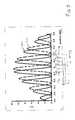
- FIG. 6shows a graph illustrating compound detector signals as function of frequency
- FIG. 7shows a graph illustrating phase signals obtained from the compound signals shown in FIG. 6 ;
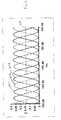
- FIG. 8shows a graph illustrating feedback signals used for stabilizing frequency of the laser
- FIGS. 9 and 10schematically illustrate other approaches to generating an optical signal used for wavelength locking using a reflective wedge mirror according to the present invention.
- FIG. 11schematically illustrates a diffractive NPE according to an embodiment of the invention
- FIG. 12schematically illustrates a Fresnel NPE according to an embodiment of the invention.
- FIG. 13schematically illustrates a binary NPE according to an embodiment of the invention.
- the inventionis related to another invention entitled “METHOD FOR CONTINUOUS WAVELENGTH LOCKING”, filed on even date herewith by G. Hedin, having a U.S. patent application Ser. No. 10/015,151, and “ROBUST WAVELENGTH LOCKER FOR CONTROL OF LASER WAVELENGTH” filed on even date herewith by G. Hedin and J. Tegin, having a U.S. patent application Ser. No. 10/014,278, both of which are incorporated herein by reference.
- the inventionprovides a compact wavelength monitoring assembly for use in conjunction with tunable laser sources.
- the wavelength monitoring assemblyis used for stabilization of the emission wavelength and for locking the wavelength to an electrical reference signal.
- the compact optical configuration of the assemblymakes the device particularly well suited for incorporation inside standard packages that are used in telecommunications applications.
- a fringe-producing optical elementis illuminated and produces an interference fringe pattern.
- the fringe-producing optical elementmay be an etalon, typically a solid etalon, that has one surface non-parallel with respect to the other surface.
- the non-parallel surfacemay be curved, stepped or flat.
- the interference fringe patternmoves and is monitored by a set of detectors having a spatial distribution chosen to match the interference pattern, thereby sampling the interference pattern at fixed positions with known spatial phase differences. From the detector signals, it is possible to determine the spatial phase ⁇ (fringe position) of the interference pattern.
- the phase signalchanges by 2 ⁇ for a laser frequency shift equal to one free spectral range (FSR). At least three detector signals are used to uniquely identify the phase of an interference pattern.
- the output power from the lasermay be inferred from the detected signals, and so there is no need for a separate power monitor.
- the frequency locking systembased on the use of at least three signals is robust, and permits locking to any desired frequency. Since the wavelength and the frequency of light are related, it will be appreciated that these terms, in some instances, may be used interchangeably.
- Another advantageis that no etalon tuning is needed since the absolute value of FSR only affects the derivative d ⁇ /df or, equivalently, d ⁇ /d ⁇ . In other words, absolute value of FSR affects the speed of the fringe pattern motion with changing frequency. Passive alignment of the etalon is possible due to the weak dependence on FSR.
- Another advantageis that the locker is able to lock frequencies on an irregular frequency grid, since no matching of the etalon transmission curve to the frequency grid is needed.
- a laser stabilized using the present inventionmay be employed in a DWDM communications system 100 , schematically illustrated in FIG. 1 .
- the system 100includes a WDM transmitter unit 102 that includes a number of lasers 104 a - 104 n operating at different wavelengths, ⁇ 1 - ⁇ n. Any of the lasers 104 a - 104 n may be a laser whose wavelength is stabilized according the present invention.
- one or more spare lasers 105may operate as a substitute if any of the lasers 104 a - 104 n fail.
- the lasers 104 a - 104 n and 105may each include modulators for modulating information onto the respective output light beams.
- the outputs from the lasers 104 a - 104 n , 105may be combined in a DWDM combiner arrangement 106 and launched as a DWDM signal into an optical fiber communications link 108 that is coupled to a DWDM receiver 110 .
- the fiber link 108may include one or more fiber amplifier stages 112 to amplify the DWDM signal as it propagates to the DWDM receiver 110 .
- Other elements, such as isolators, switches, add/drop multiplexers and the likemay also be disposed along the fiber link 108 .
- the DWDM receiver 110demultiplexes the received DWDM signal in a demultiplexer 114 and directs signals at different wavelengths ⁇ 1 - ⁇ n to respective channel detectors 116 a - 116 n.
- FIG. 2A block schematic diagram showing various elements of a frequency stabilized laser unit 200 is illustrated in FIG. 2.
- a laser 202generates an output light beam 204 that is directed to a wavelength detector unit 206 , which generates an output signal 208 determined by the wavelength of the light in the light beam 204 .
- the lasermay be any suitable type of semiconductor laser that produces a tunable output.
- Monolithically tunable lasersare often used in optical communications applications, such as distributed Bragg reflector (DBR) lasers, grating coupled, sampled Bragg reflector (GCSR) lasers, for example as described in “74 nm Wavelength Tuning Range of an InGaAsP Vertical Grating Assisted Codirectional Coupler Laser with Rear Sampled Grating Reflector” by M. Oberg et al., IEEE Photonics Technology Letters, Vol. 5, No. 7, pp. 735-738, July 1993, incorporated herein by reference, and in U.S. Pat. No. 5,621,828, also incorporated herein by reference, and vernier, dual DBR lasers, for example as described in U.S. Pat. No. 4,896,325.
- DBRdistributed Bragg reflector
- GCSRsampled Bragg reflector
- a residual output beam 210passing from the wavelength detector unit 206 , may carry optical output power not used in the determination of the wavelength.
- the residual output beam 210may be used as the useful optical output from the laser 202 .
- the wavelength detector unit 206advantageously uses only a small fraction, for example a few percent, of the output light beam 204 , in order to increase the power in the residual output beam 210 .
- a wavelength analyzer unit 212receives and analyzes the output signal 208 from the wavelength detector unit 206 to determine the wavelength of the light beam 204 .
- the analyzer 212typically generates an error signal 214 that is directed to a wavelength controller.
- the size of the error signaltypically indicates the amount by which the measured wavelength of the laser deviates from a desired value.
- the error signal 214is directed to a tuning controller 216 that is connected to the laser 202 and controls the operating wavelength of the laser 202 .
- the wavelength tuning controller 216may be incorporated with a laser controller 218 that includes the power supply 220 for providing power to the laser 202 and a temperature controller 222 that controls the temperature of the laser 202 .
- the laser 202may be coupled, for example, to a thermoelectric device 224 or other type of device for adjusting temperature.
- the laser 202 and wavelength detector unit 206may be enclosed within a housing 226 to prevent environmental effects from affecting the operation of the laser 202 and the wavelength detector unit 206 .
- the device 224 for adjusting operating temperaturemay also be located within the housing 226 .
- FIG. 3One particular embodiment of a wavelength stabilized detector unit is illustrated in FIG. 3 .
- the laser 302generates an output light beam 304 whose divergence is reduced by a focusing unit 306 .
- the focusing unitmay include one or more lenses.
- the light beam 308 passing out of the focusing unit 306may be approximately collimated, or may be convergent or divergent. For purposes of clarity, it is assumed in the following description that the light beam 308 is collimated. It will be appreciated, however, that the present invention also operates convergent and divergent light.
- the light beam 308may pass through an optical isolator 310 , which permits light to pass in the forward direction, but which prevents light passing in the backwards direction towards the laser 302 . This prevents reflected light from re-entering the cavity of the laser 302 and adversely affecting the stability of the light 304 output from the laser.
- a beamsplitter 312splits a fraction 314 of the light 308 as a probe beam.
- the beamsplitter 312may be, for example, a flat piece of glass with one side antireflection coated, where the probe beam 314 is split off by reflection from the uncoated surface.
- the beamsplitter 312may also be a beamsplitter cube or any other suitable form of optical element that samples the light 308 from the laser 302 .
- the light transmitted through the beamsplitter 312forms the residual beam 318 , which may be directed to a focusing unit 320 , typically one or more lenses, for coupling into the output fiber 322 .
- the optical power coupled into the output fiber 322constitutes the useful output light from the laser 302 and may be used to form an optical communications signal.
- the output fiber 322may lead first to a modulator for imposing information on the light propagating along the fiber 322 .
- the optical power in the probe beam 314is around a few percent of the power in the residual beam 318 .
- the probe beam 314is directed to a fringe-producing optical element 316 , such as a non-parallel etalon (NPE).
- a fringe-producing optical element 316such as a non-parallel etalon (NPE).
- NPEnon-parallel etalon
- the fringe-producing optical element 316is a NPE.
- a fringe-producing optical elementWhen illuminated with a beam of light, a fringe-producing optical element produces a second beam of light that includes an interference pattern, having interference fringes.
- the second beam of lightmay be reflected from the fringe-producing optical element or may be transmitted from the fringe-producing element.
- the second beamis formed by two interfering beam components arising from two different surfaces of the fringe-producing element.
- the probe beam 314propagates to the NPE 316 , which operates as a spatial wavelength selective filter.
- the NPE 316is formed from material that transmits light at the output wavelength of the laser 302 , for example glass or plastic.
- An NPEhas surfaces that contain portions that are non-parallel, and may be wedged or may include at least one non-planar surface.
- a non-planar surfacemay assume any type of shape, including spherical, aspherical, toroidal, cylindrical, or stepped shapes. If the etalon includes a non-planar surface, it may be referred to as a non-planar etalon.
- a NPE having a stepped surfacemay be, for example, a binary optic etalon or a Fresnel etalon, as described below.
- a NPE having a stepped surfacemay also have a wedged or curved profile.
- the NPE 316has first and second faces 324 and 326 that are flat, but not parallel to each other, and so the NPE 316 is wedged.
- the reflectivity of the first face 324is R1 and the reflectivity of the second face 326 is R2.
- the magnitudes of the surface reflectivities, R1 and R2may be equal, although they need not be equal.
- the NPE 316is formed from glass having uncoated surfaces 324 and 326 , then the reflectivities R1 and R2 are determined by the difference in refractive index between the material of the NPE 316 and the medium in which the NPE 316 is immersed.
- the reflectivity of each surface 324 and 326is around 4%, when the angle of incidence on the faces 324 and 326 is close to normal. It will be appreciated that the surfaces 324 and 326 may also be provided with coatings having specific reflective values in the range from greater than 0% to almost 100%. In the present invention, the reflectivities R1 and R2 may lie in the range 1%-50%, and more preferably in the range 10%-25%. The values of R1 and R2, however, need not be restricted to these ranges.
- the probe beam 314is partially reflected at the first surface 324 and partially transmitted into the material of the NPE 316 .
- This partially transmitted beampropagates towards the second surface 326 where it is again partially transmitted and partially reflected.
- the lightundergoes a series of internal reflections within the NPE 112 .
- the total optical power reflected from the NPE 316 towards the beamsplitter 312may be determined from coherent addition of all partially reflected beams. Where the reflectivity is low, however, for example 10% or lower, then the light reflected by the NPE 316 is primarily the light that was reflected only once, by either the first or second surface 324 or 326 .
- the light reflected by the first surface 324is labeled beam 328 (solid lines) and the light reflected by the second surface 326 is labeled as 330 (dotted lines), although it is understood that a component of the reflected signal corresponds to light that was reflected within the NPE 316 multiple times.
- the beams 328 and 330pass through the beamsplitter 312 and are incident on a detector unit 332 that includes at least three detector elements 334 , also referred to as detector pixels.
- the pixels 334may be arranged in an array.
- the shape of the pixels 334may be adapted so as to increase the overlap with the interference fringes of the interference pattern formed in the light by the NPE 316 .
- the interference patternincludes parallel fringes and the pixels 334 may be rectangular, and elongated in the direction perpendicular to the fringe separation.
- the resulting interference fringesmay be curved and the pixels may be curved to match the curves of the interference fringes.
- the detector unit 332may be mounted on a detector carrier 336 , which provides mechanical support for the detector unit 332 which may also provide electrical contact between the detector unit 332 and the control unit (not shown).
- the carrier 336may be formed from an electrically insulating material, such as alumina or the like, and may be provided with bond pads for forming electrical contacts.
- the detector carrier 336 , beamsplitter 312 and NPE 316may all be mounted on a mounting plate 338 that provides a thermal, electrical and/or mechanical interface between the NPE 316 , detector carrier 332 and beamsplitter 312 , and the rest of the laser housing 226 .
- the design of the mounting plate 338may provide solder and bond pads and may also include electrical circuit lines for electrical connections.
- the mounting plate 338may be formed from an electrically insulating material, although it is also advantageous that the carrier be a good thermal conductor. Accordingly, the mounting plate may be formed from alumina, aluminum nitride, or some other ceramic having good thermal conductive properties.
- Interference between light reflected from the first and second surfaces 324 and 326results in spatial modulation of the light incident on the detector unit 332 .
- the spatial modulationis typically periodic, although depending on the curvature of the surfaces 324 and 326 of the NPE 316 , the period may vary across the detector unit 332 . In the illustrated example of a wedged reflector, having flat surfaces 324 and 326 , the period of the interference pattern is constant across the detector unit 332 .
- the detector unit 332has at least three pixels 334 that detect different parts of the spatially modulated interference pattern.
- the three, or more, pixels 334are positioned so as to detect different parts of the interference pattern that correspond to different spatial phase.
- the NPE 316 and detector unit 332are advantageously designed to match each other so that the spacing of the pixels 334 is such that the pixels 334 are positioned to detect evenly spaced portions of a period of the interference pattern. For example, if the detector unit 332 uses three pixels, then uniform spacing between pixels, which permits simultaneous power monitoring, corresponds to a phase difference of the periodic interference pattern of about 2 ⁇ /3. More generally, where the detector unit 332 employs n pixels 334 , then the spacing between pixels 334 corresponds to 2 ⁇ /n. It will be appreciated that adjacent pixels 334 may be have different spacings, for example may also be spaced apart by a distance corresponding to m ⁇ +2k ⁇ /n, where k and m are integers.
- the diffraction and pointing sensitivityis much reduced since only linear spatial modulation in one direction is measured.
- the degradation propertiesare improved since all pixels 334 are manufactured on the same chip.
- the manufacturing and assembling of the wavelocker systemrequires only alignment of the etalon by rotation about one axis, and alignment of the detectors by translating along another axis, in order to correctly map the pattern on to the detectors.
- an interference pattern 402is shown as light intensity (in arbitrary units) as a function of spatial position, measured in mm.
- the period of the interference pattern 402is P and, in this example where three pixels 434 a , 434 b and 434 c are used, the spacing between the pixels 434 a , 434 b and 434 c is P/3.
- the interference pattern 402was obtained from simulations of a NPE formed from BK7 glass, having a refractive index of 1.51 at a design wavelength of 1.55 ⁇ m.
- the assumed thickness of the NPEwas 2 mm and the wedge angle was 0.2°, resulting in a fringe spacing in the interference pattern of about 150 ⁇ m.
- the surface reflectivitywas in the range 10%-20%.
- the spacing between pixels 334 of the detector unit 332is 50 ⁇ m.
- the pixelsmay be 500 ⁇ m high and 25 ⁇ m wide.
- the choice of reflection coefficient of the NPEis a compromise between fringe shape, modulation depth, optical power and ghost fringes.
- Sinusoidal patternsare often preferred for various feedback detection schemes, and are obtained for reflection coefficients less than about 10%.
- Near-sinusodial fringe patternsare obtained for reflection coefficients in the range of about 10%-25%, and when the reflection coefficient is greater than about 25%, the fringe pattern assumes a periodical Lorentzian shape, characterized by sharp peaks and broad valleys.
- the MD of a reflected interference patternis close to 100% where the reflection coefficient is less than about 25%.
- the modulation depth of an interference pattern transmitted through the NPEincreases, at least for small values of R, as 2 ⁇ R. Therefore, an uncoated NPE having a surface reflection of 4% manifests a MD of 8%.
- the fraction of optical power in the reflected patternis about 2 ⁇ R, and about 1 ⁇ (2 ⁇ R) in the transmitted pattern. Therefore, the ratio of transmitted to reflected power is about 11 for an uncoated NPE having a surface reflection of about 4%.
- Ghost fringesmay occur for higher values of reflection, typically about 25% and more, due to multiple reflections in the NPE. These ghost fringes at best create a background that reduces the MD, and at worst cause higher spatial frequencies in the interference pattern. Therefore, when detecting a reflected interference pattern, the surface reflectivity of the NPE is advantageously low to increase the MD and to make the fringe pattern more closely sinusoidal. It will be understood that the surface reflectivity may be have a lower boundary set by the minimum acceptable level of optical power at the detector chip. For a configuration such as that as illustrated in FIG. 3 , an optimal value for the surface reflectivity may lie in the range 5%-15%. Where the fringe pattern transmitted through the NPE is detected, the value of R should be high to increase the MD, but not so high as to cause higher order distortions of the fringe pattern. A typical value of reflectivity for an NPE operating in transmission is around 30%.
- the detector unit 332may be positioned behind the NPE 316 to detect the interference pattern on the light transmitted through the NPE 316 .
- the interference pattern of light transmitted through the NPE 316has a relatively low modulation depth.
- the modulation depth of the interference pattern reflected from the NPE 316is relatively high. Therefore, use of the interference pattern reflected from the NPE 316 provides advantages in signal to noise.
- the phase of the interference pattern 402is, therefore, a direct measurement of the output laser frequency, at least over a frequency range equal to the FSR.
- the output signal from the first pixel 434 amay be termed R
- the output signal from the second pixel 434 bmay be termed S
- the output from the third pixel 434 cmay be termed T.
- the sum of the optical signals on the pixels 434is a direct measurement of the average irradiance on to the detector chip. Consequently, so long as there is adequate calibration, for example to extract variations in signal level due to the intensity envelope 404 , the sum of the signals from the pixels (R+S+T) is proportional to the total laser power.
- FIG. 5shows the interference pattern 502 formed when the laser output is at a first frequency, and a second interference pattern 504 formed when the laser output is changed to a second frequency.
- the fringe patternis seen to move across the detector unit 332 when the laser frequency changes. This movement is detected by the detector unit 332 , since the signals produced by the different pixels 434 change.
- the pixels 534 a - 534 fcover a span of two periods of the interference patterns 402 and 502 .
- the outputs from two pixels spaced apart by the periodmay be combined.
- the outputs from pixels 534 a and 534 dmay be combined to form signal R
- the outputs from pixels 534 b and 534 emay be combined to form signal S
- the outputs from pixels 534 c and 534 fmay be combined to form signal T.
- the inter-pixel spacing for the pixels 534 a - 534 fis P/3.
- FIG. 6shows the values of R, S, and T as functions of the frequency of the light incident on the NPE 316 .
- the values of R (curve 602 ), S (curve 604 ), and T (curve 606 )all vary periodically with increasing frequency of the incident light.
- the signals R, S, and Tare equally spaced from each other.
- RI 0 (1+cos( ⁇ + ⁇ ))
- SI 0 (1+cos( ⁇ ))
- TI 0 (1+cos( ⁇ ))
- ⁇is the phase of the interference fringe
- ⁇is the phase difference between adjacent pixels
- I 0is the average light irradiance.
- ⁇has a value equal to 2 ⁇ /3 (120°).
- the following signalsmay be calculated from the measured values of R, S, and T.
- the average signal 608 in FIG. 6represents I.
- the laseris first tuned to the locking value, f 0 , in other words that value to which it is desired to lock the laser, and the detector signals, R, S, and T, for that frequency are stored as R 0 , S 0 and T 0 .
- R 0 , S 0 and T 0are then used in expressions (2), (3) and (4) to calculate reference phase signals, sin( ⁇ 0 ), cos( ⁇ 0 ) and ⁇ 0 .
- the reference phase signalsmay be used to calculate a feed-back signal along with the phase signals, sin( ⁇ ), cos( ⁇ ) and ⁇ , from the measured signals.
- the first feedback signalis sin ( ⁇ ′), expression (7). This has a capture range of ⁇ FSR/2, and has a nonlinear response. This is termed sine feedback.
- the other feedback signalis ⁇ ′, as provided in expression (8). This feedback signal has a capture range of ⁇ FSR/4 and has a linear response. This is termed phase feedback. Phase feedback provides the advantage over sine feedback that the response is linear, however, more processing is required to calculate ⁇ ′ than is required to calculate sin( ⁇ ′).
- the values of sin ( ⁇ ′), curve 802 , and ⁇ ′, curve 804are shown in FIG. 8 , plotted against frequency of the light being locked.
- the signal cos( ⁇ ′)may also be used as a feedback signal.
- any frequencymay be locked on to with the same capture range and response slope, and that the absolute thickness and tilt of the etalon is a weak variable that only determines the slope of the feed-back signal at the locking point and the absolute capture range.
- Another advantageis that the intensity may be inferred from the signals received by the detector unit 332 that is used to measure the wavelength, and no additional power monitor is required.
- the spacing between the maxima of the interference patternmay not be constant.
- the spacings between adjacent pixels in the detector unitneed not be constant, but may be selected to suit the nonlinearity of the interference pattern.
- the pixelsmay still be spaced apart by a uniform inter-pixel spacing: the feedback scheme is robust and does not require exact inter-pixel spacing for operation. For example, in a three pixel detector scheme, adequate feedback may still be provided where the spacing between pixels is 2 ⁇ /3 ⁇ /6, even where the NPE is a wedged etalon. The feedback technique may also operate outside this range, but with decreased effectiveness.
- FIG. 9Another embodiment of a wavelength detector unit 900 is schematically illustrated in FIG. 9 .
- light 904diverges from a laser 902 and is substantially collimated by a focusing unit 906 .
- the collimated beam 908passes through a NPE 912 that reflects light from both surfaces 911 and 913 .
- the NPE 912is a reflective wedge, although it may also include one or more curved surfaces.
- the light 918 that is not reflected by the NPE 912may be focused by a lens unit 920 to an output fiber 922 .
- the light 928 (solid lines) reflected from the first surface 911 and the light 930 (dashed lines) reflected from the second surface 913may be reflected by a reflector 916 to the detector unit 932 .
- the detector unit 932has three or more pixels 934 to detect the interference pattern caused by the interference between the reflected light beams 928 and 930 .
- the NPE 912may be formed from BK7 glass having a refractive index of 1.51 at the design wavelength of 1.55 ⁇ m.
- a wedge angle of 0.2°produces a fringe spacing in the resultant interference pattern of about 150 ⁇ m.
- a thickness of 1 mmgives an FSR of 100 GHz, while a thickness of 2 mm gives an FSR of 50 GHz.
- the reflectivity of the surfaces 911 and 913may be in the range of approximately 1%-2% in order to reduce insertion loss in the beam 918 .
- the reflectivitymay be less than 1%, so long as the minimum power requirements of the detector unit 932 are satisfied. Higher values of reflectivity may not provide significant benefit in terms of signal to noise or reduction of higher order reflections, but do increase the insertion loss.
- the angle of incidence on the NPE 912may be around 15°, although any suitable angle may be used, depending on the beam diameter and the thickness of the NPE 912 . Where the beam diameter is fixed, a thicker NPE 912 is advantageously tilted at a smaller angle, to ensure good overlap between the beams reflected from the two surfaces 911 and 913 . Since the reflectivity of the surfaces 911 and 913 is typically low, any interference or etalon effects in the beam 918 transmitted to the output fiber 922 resulting from the NPE 912 may be regarded as being insignificant.
- One of the advantages of placing the NPE 912 directly in the beam 908is that all light reflected out of the beam 908 by the NPE 912 is incident on the detector unit 932 , and therefore the use of the tapped light is very efficient. This contrasts, for example, with the embodiment illustrated in FIG. 3 , where light transmitted through the NPE 316 is not used for measuring the wavelength of the light. Furthermore, passing the light 328 and 330 through the beamsplitter 312 results in additional losses.
- wavelength detector unit 1000is illustrated in FIG. 10 .
- the folding mirror 916has been omitted and the light 928 and 930 reflected by the NPE 912 is incident directly on the detector unit 932 .
- the detector unit 932is positioned sufficiently far from the NPE 912 that the detector unit 932 receives the reflected light 928 and 930 but does not occlude any of the light 908 incident on the NPE 912 .
- the interference pattern from the two reflected beams 928 and 930occurs only where the two beams 928 and 930 overlap.
- ⁇the wedge angle of the NPE 912 is sufficiently small that the contribution to ⁇ from the wedged shape of the wedge may be neglected.
- the displacementis about 330 ⁇ m, and so the interference pattern has a width of about 670 ⁇ m.
- Such an etalonhas a FSR of 100 MHz.
- the incident angle ⁇is reduced to allow for a thicker etalon while maintaining the same width of the interference pattern.
- Another approachis to use an optically denser etalon material. Reducing ⁇ , however, increases the length of the wavelength locker since the detector unit 932 must be placed further away from the etalon in order not to shade the incoming light 908 .
- the overall length requirementcan be some what reduced.
- the wedge angle of the NPE 912is small, in many cases less than 1°, and so the walk-off between the two beams 928 and 930 propagating from the NPE 912 to the detector unit 932 is very small, if not negligible. Therefore, although they have been described as separate beams, the reflected beams 928 and 930 may together be regarded as a single beam, derived from the output beam 980 of the laser, that contains an interference pattern.
- the reflectoris a diffractive etalon 1100 having a first side 1102 and a second side 1104 .
- the first and second sides 1102 and 1104may or may not be parallel to each other.
- the light 1106 from the laser to be wavelength lockedis incident on the first side 1102 .
- a diffracting structure 1108having a grating period d 1 , is disposed on the first side 1102 , so that a portion of the incident light 1106 is diffracted as beam 1110 (solid lines), at an angle ⁇ 1 to the incident light 1106 .
- the light 1112 that is transmitted through the first side 1102is incident on the second side 1104 .
- the second side 1104is provided with a second diffracting structure 1114 , having a grating period d 2 , so that some of the light incident on the second side 1104 is diffracted as beam 1116 (dashed lines) at an angle ⁇ 2 relative to the incident light 1106 .
- the two beams 1110 and 1116overlap and interfere to cause a fringe pattern that may be detected by a multi-element detector unit 1118 to produce detection signals that are used for determining the wavelength of the light 1106 .
- the diffractive etalon 1100produces two beams 1110 and 1116 that propagate in different directions and, therefore, may be considered to be a wedged reflector, even though the two surfaces 1102 and 1104 may be parallel. It will be appreciated that the light 1106 incident on the diffractive etalon 1100 need not be incident at normal incidence.
- the diffracting structures 1108 and 1114may reflectively diffract, as illustrated in FIG. 11 , in which case the diffractive etalon 1100 may be used in the embodiments of wavelength locker similar to those illustrated in FIGS. 3 , 9 and 10 .
- the diffracting structures 1108 and 1114may also diffract in transmission, rather than reflection, in which case the diffractive etalon 1100 may be employed in other configurations.
- a Fresnel etalon 1200is a NPE that may be used in a wavelength locker.
- the Fresnel etalon 1200has first and second surfaces 1202 and 1204 .
- the long surfaces 1206are not parallel to the first surface 1202 , but are at an angle relative to the first surface 1202 .
- the long surfaces 1206may be flat or curved.
- the average thickness across the Fresnel etalon 1200may be constant, or may vary. It will be appreciated that one or both of the surfaces 1202 and 1204 may be provided with a ridged pattern of long and short surfaces.
- light 1210is incident on the Fresnel etalon 1200 .
- the first surface 1202reflects a portion of the light 1210 as beam 1212 (solid lines) and the second surface reflects a portion of the light 1210 as beam 1214 (dashed lines).
- the light that is not reflected by either the first or second surfaces 1202 and 1204is transmitted as beam 1216 .
- the two reflected beams 1212 and 1214overlap and interfere, causing an interference pattern that may be detected by a detector unit.
- a binary etalon 1300is a NPE that may be used in a wavelength locker.
- the binary etalon 1300has first and second surfaces 1302 and 1304 .
- the long surfaces 1306are parallel to the first surface 1302
- the short surfaces 1308are not parallel to the first surface 1302 .
- the average thickness across the binary etalon 1300varies from one side of the etalon 1300 to the other. It will be appreciated that one or both of the surfaces 1302 and 1304 may be provided with a stepped pattern of long and short surfaces.
- light 1310is incident on the binary etalon 1300 .
- the first surface 1302reflects a portion of the light 1310 as beam 1312 (solid lines) and the second surface reflects a portion of the light 1310 as beam 1314 (dashed lines).
- the light that is not reflected by either the first or second surfaces 1302 and 1304is transmitted as beam 1316 .
- the two reflected beams 1312 and 1314overlap and interfere, causing an interference pattern that may be detected by a detector unit.
- the Fresnel etalon 1200 and the binary etalon 1300may be used in different configurations of wavelength locker.
- the Fresnel etalon 1200 or binary etalon 1300may be used in a wavelength locker where light is first split from the output beam of the laser to form a second beam that is subsequently incident on the etalon 1200 or 1300 .
- One example of such a configurationis shown in FIG. 3 .
- the Fresnel etalon 1200 or binary etalon 1300may also be placed directly in the output beam of the laser, for example as is illustrated in the configurations shown in FIGS. 9 and 10 .
- an etalonmay have flat and parallel surfaces and have a refractive index that is not uniform across the etalon.
- One example of such an etalonis a gradient index (GRIN) lens.
- the variation in refractive indexneed not be radial from an axis, as is commonly found in a GRIN lens.
- the refractive index of the non-uniform index etalonmay increase from one side of the etalon to the opposite side.
- the profile of the refractive index variationmay be linear, parabolic, or may be any suitable function of distance across the etalon that results in a fringe pattern being formed in the reflected light.
- the refractive indexmay also vary through the etalon, in a direction along the direction of light propagation through the etalon.
- the present inventionis applicable to wavelength locking of tunable lasers, and is believed to be particularly useful for locking the wavelength of semiconductor lasers used for optical communications.
- the present inventionshould not be considered limited to the particular examples described above, but rather should be understood to cover all aspects of the invention as fairly set out in the attached claims.
- Various modifications, equivalent processes, as well as numerous structures to which the present invention may be applicablewill be readily apparent to those of skill in the art to which the present invention is directed upon review of the present specification. The claims are intended to cover such modifications and devices.
Landscapes
- Physics & Mathematics (AREA)
- Condensed Matter Physics & Semiconductors (AREA)
- General Physics & Mathematics (AREA)
- Electromagnetism (AREA)
- Optics & Photonics (AREA)
- Semiconductor Lasers (AREA)
- Lasers (AREA)
Abstract
Description
R=I0(1+cos(φ+α))
S=I0(1+cos(φ)), and
T=I0(1+cos(φ−α))
where φ is the phase of the interference fringe, α is the the phase difference between adjacent pixels and I0is the average light irradiance. For three-pixel detection, where the detectors are spaced evenly over a period of the interference pattern, α has a value equal to 2π/3 (120°). The value of φ depends on the free spectral range (FSR) of the etalon and the frequency, f, of the incoming light through the expression: φ=4πf mod (FSR), where f mod (FSR) is the remainder after highest possible intergral number of FSRs is substracted from the frequency. For example, if the frequency is given by f=191,045 GHz, and the FSR is 100 GHz, then f mod (FSR) is 45 GHz.
I=(R+S+T)/3 (1)
where I is independent of φ and is equal to I0. Therefore, I is proportional to the laser power incident on the
sin(φ)=(T−R)/(I√3). (3)
Therefore, one value of φ may be calculated as:
φ=tan−1[sin(φ)/cos(φ)] (4)
cos(φ′)=cos(φ0)cos(φ)+sin (φ0)sin(φ) (6)
sin(φ′)=−sin(φ0)cos(φ)+cos(φ0)sin(φ) (7)
φ′=tan−1(sin(φ′)/cos(φ′)) (8)
Claims (34)
Priority Applications (1)
| Application Number | Priority Date | Filing Date | Title |
|---|---|---|---|
| US10/014,277US6859469B2 (en) | 2001-12-11 | 2001-12-11 | Method and apparatus for laser wavelength stabilization |
Applications Claiming Priority (1)
| Application Number | Priority Date | Filing Date | Title |
|---|---|---|---|
| US10/014,277US6859469B2 (en) | 2001-12-11 | 2001-12-11 | Method and apparatus for laser wavelength stabilization |
Publications (2)
| Publication Number | Publication Date |
|---|---|
| US20030108071A1 US20030108071A1 (en) | 2003-06-12 |
| US6859469B2true US6859469B2 (en) | 2005-02-22 |
Family
ID=21764499
Family Applications (1)
| Application Number | Title | Priority Date | Filing Date |
|---|---|---|---|
| US10/014,277Expired - LifetimeUS6859469B2 (en) | 2001-12-11 | 2001-12-11 | Method and apparatus for laser wavelength stabilization |
Country Status (1)
| Country | Link |
|---|---|
| US (1) | US6859469B2 (en) |
Cited By (2)
| Publication number | Priority date | Publication date | Assignee | Title |
|---|---|---|---|---|
| US20040161194A1 (en)* | 2003-02-14 | 2004-08-19 | Michael Mittelstein | Photonic integrated circuit based planar wavelength meter |
| US20060139727A1 (en)* | 2004-12-28 | 2006-06-29 | Rachid Gafsi | Hybrid fiber polarization dependent isolator, and laser module incorporating the same |
Families Citing this family (6)
| Publication number | Priority date | Publication date | Assignee | Title |
|---|---|---|---|---|
| US20050019037A1 (en)* | 2003-07-25 | 2005-01-27 | Luo Xin Simon | To can laser package with front monitoring photodetector and turning mirror |
| US7502568B1 (en) | 2003-12-04 | 2009-03-10 | National Semiconductor Corporation | Method of using low bandwidth sensor for measuring high frequency AC modulation amplitude |
| US7630422B1 (en) | 2005-01-14 | 2009-12-08 | National Semiconductor Corporation | Driver for vertical-cavity surface-emitting laser and method |
| JP4720489B2 (en)* | 2005-06-21 | 2011-07-13 | ソニー株式会社 | Laser equipment |
| WO2012161083A1 (en)* | 2011-05-24 | 2012-11-29 | 住友電気工業株式会社 | Pulsed light source |
| US9817158B2 (en)* | 2015-01-22 | 2017-11-14 | INVIS Technologies Corporation | Gradient index lens for infrared imaging |
Citations (57)
| Publication number | Priority date | Publication date | Assignee | Title |
|---|---|---|---|---|
| US3612691A (en) | 1969-02-07 | 1971-10-12 | Sanders Associates Inc | Monchromaticity detector |
| US4170416A (en) | 1977-01-17 | 1979-10-09 | The Perkin-Elmer Corporation | Apparatus for analyzing coherent radiation |
| US4173442A (en) | 1977-05-27 | 1979-11-06 | The United States Of America As Represented By The Secretary Of Commerce | Apparatus and method for determination of wavelength |
| US4515478A (en) | 1982-11-05 | 1985-05-07 | Systems Research Laboratories, Inc. | Coherent light detecting system including passive averaging network |
| JPS60243604A (en) | 1984-05-18 | 1985-12-03 | Olympus Optical Co Ltd | Depolarization plate |
| US4566794A (en) | 1981-04-22 | 1986-01-28 | Honeywell Inc. | Apparatus for interference fringe shift sensing |
| JPS62242378A (en) | 1986-04-14 | 1987-10-22 | Komatsu Ltd | Laser light wavelength control method |
| US4896325A (en) | 1988-08-23 | 1990-01-23 | The Regents Of The University Of California | Multi-section tunable laser with differing multi-element mirrors |
| JPH0239582A (en) | 1988-07-29 | 1990-02-08 | Toshiba Corp | Narrowband laser device |
| JPH02153583A (en) | 1988-12-06 | 1990-06-13 | Mitsubishi Electric Corp | Wavelength stabilization control device |
| US4947398A (en)* | 1988-10-20 | 1990-08-07 | Mitsubishi Denki Kabushiki Kaisha | Laser device with wavelength stabilization control and method of operating the same |
| US5121371A (en)* | 1990-06-18 | 1992-06-09 | Bernoulli Optical Systems Company | Optical servo system for magnetic disk |
| US5130998A (en)* | 1990-02-21 | 1992-07-14 | Mitsubiski Denki Kaubshiki Kaisha | Laser device with oscillation wavelength control |
| US5167444A (en) | 1990-08-13 | 1992-12-01 | Litton Systems, Inc. | Apparatus and method for optical signal source stabilization |
| US5202878A (en)* | 1990-05-24 | 1993-04-13 | Olympus Optical Co., Ltd. | Optical recording and reproducing method and apparatus for the same |
| JPH05102589A (en) | 1991-10-11 | 1993-04-23 | Mitsui Petrochem Ind Ltd | Method and device for stabilizing output of laser device |
| US5323409A (en) | 1991-12-05 | 1994-06-21 | Honeywell Inc. | Wavelength stabilization |
| US5428700A (en) | 1994-07-29 | 1995-06-27 | Litton Systems, Inc. | Laser stabilization |
| WO1995020144A1 (en) | 1994-01-20 | 1995-07-27 | British Telecommunications Public Limited Company | Optical wavelength sensor |
| US5515468A (en) | 1993-02-23 | 1996-05-07 | The Whitaker Corporation | Light bending devices |
| US5621828A (en) | 1992-09-24 | 1997-04-15 | Interuniversitair Micro-Elektronica Centrum Vzw | Integrated tunable optical filter |
| EP0818859A1 (en) | 1996-07-11 | 1998-01-14 | Nortel Networks Corporation | Wavelength monitoring and control assembly for WDM optical transmission systems |
| US5715265A (en) | 1995-09-26 | 1998-02-03 | Northern Telecom Limited | Dispersion compensation |
| US5798859A (en) | 1995-07-27 | 1998-08-25 | Jds Fitel Inc. | Method and device for wavelength locking |
| US5828689A (en) | 1996-07-20 | 1998-10-27 | Northern Telecom Limited | Etalon arrangement |
| EP0911621A2 (en)* | 1997-10-14 | 1999-04-28 | Fujitsu Limited | Optical device for wavelength monitoring and wavelength control |
| US5917596A (en)* | 1996-01-26 | 1999-06-29 | The Secretary Of State For Defence In Her Brittanic Majesty's Government Of The United Kingdom Of Great Britain And Northern Ireland | Radiation field analyzer using interference patterns |
| US5943152A (en) | 1996-02-23 | 1999-08-24 | Ciena Corporation | Laser wavelength control device |
| US5956356A (en) | 1997-12-08 | 1999-09-21 | Lucent Technologies Inc. | Monitoring wavelength of laser devices |
| US5963686A (en) | 1997-06-24 | 1999-10-05 | Oplink Communications, Inc. | Low cost, easy to build precision wavelength locker |
| WO2000023764A1 (en) | 1998-10-16 | 2000-04-27 | New Focus, Inc. | Interferometer for optical wavelength monitoring |
| US6064681A (en) | 1999-06-11 | 2000-05-16 | Lucent Technologies Inc. | Wavelength stabilized, tunable optical transmitter with high SMSR |
| US6067181A (en) | 1997-11-13 | 2000-05-23 | Ciena Corporation | Laser locking and self filtering device |
| US6094271A (en) | 1998-01-29 | 2000-07-25 | Ando Electric Co., Ltd. | Wavelength measuring system |
| US6111681A (en) | 1996-02-23 | 2000-08-29 | Ciena Corporation | WDM optical communication systems with wavelength-stabilized optical selectors |
| US6122301A (en) | 1998-06-17 | 2000-09-19 | Santec Corporation | Laser light source apparatus |
| US6125128A (en) | 1997-11-13 | 2000-09-26 | Ciena Corporation | Laser output locking and self filtering device |
| US6141136A (en)* | 1999-08-27 | 2000-10-31 | Kalibjian; Ralph | Active phase-shift control in optical-hybrid etalons |
| US6151114A (en) | 1998-03-31 | 2000-11-21 | The Boeing Company | Coherent laser warning system |
| US6178002B1 (en)* | 1997-10-01 | 2001-01-23 | Thomas Mueller-Wirts | Method and device for measuring and stabilization using signals from a Fabry-Perot |
| US6186937B1 (en) | 1999-07-30 | 2001-02-13 | Lucent Technologies, Inc. | Method and device for obtaining a desired phase of optical characteristic of a fabry-perot etalon |
| US6212210B1 (en) | 1997-10-24 | 2001-04-03 | Hitachi, Ltd. | Control method and apparatus for stabilizing optical wavelength |
| US6233263B1 (en) | 1999-06-04 | 2001-05-15 | Bandwidth9 | Monitoring and control assembly for wavelength stabilized optical system |
| US6243403B1 (en) | 1999-01-11 | 2001-06-05 | Agere Systems Optoelectronics Guardian Corp | Method and apparatus for integrated optical wavelength stabilization |
| US20010007501A1 (en) | 2000-01-10 | 2001-07-12 | Krister Frojdh | Integrated wavelength monitor |
| US6272157B1 (en) | 1999-01-11 | 2001-08-07 | Agere Systems Optoelectronics Guardian Corp. | Apparatus and method for calibrating a wavelength stabilized laser |
| US6323987B1 (en) | 1999-05-14 | 2001-11-27 | Agere Systems Optoelectronics Guardian Corp. | Controlled multi-wavelength etalon |
| US6331906B1 (en) | 1997-02-10 | 2001-12-18 | Oni Systems Corp. | Method and apparatus for operation, protection and restoration of heterogeneous optical communication networks |
| US6366592B1 (en) | 2000-10-25 | 2002-04-02 | Axsun Technologies, Inc. | Stepped etalon semiconductor laser wavelength locker |
| US6433921B1 (en)* | 2001-01-12 | 2002-08-13 | Onetta, Inc. | Multiwavelength pumps for raman amplifier systems |
| US20020181519A1 (en)* | 2001-05-31 | 2002-12-05 | Altitun Ab | Apparatus and method for controlling the operating wavelength of a laser |
| US6529276B1 (en)* | 1999-04-06 | 2003-03-04 | University Of South Carolina | Optical computational system |
| US20030072010A1 (en)* | 2001-10-01 | 2003-04-17 | Boye Robert Russell | Non-etalon reflective wavelength locking optical sub-assembly and associated methods |
| US6556731B2 (en)* | 1997-06-23 | 2003-04-29 | Chiaro Networks Ltd. | Integrated optics beam deflectors and systems |
| US20030108072A1 (en)* | 2001-12-11 | 2003-06-12 | Altitun Ab | Method and algorithm for continuous wavelength locking |
| US20030107746A1 (en)* | 2001-12-11 | 2003-06-12 | Altitun Ab | Robust wavelength locker for control of laser wavelength |
| US6643025B2 (en)* | 2001-03-29 | 2003-11-04 | Georgia Tech Research Corporation | Microinterferometer for distance measurements |
- 2001
- 2001-12-11USUS10/014,277patent/US6859469B2/ennot_activeExpired - Lifetime
Patent Citations (60)
| Publication number | Priority date | Publication date | Assignee | Title |
|---|---|---|---|---|
| US3612691A (en) | 1969-02-07 | 1971-10-12 | Sanders Associates Inc | Monchromaticity detector |
| US4170416A (en) | 1977-01-17 | 1979-10-09 | The Perkin-Elmer Corporation | Apparatus for analyzing coherent radiation |
| US4173442A (en) | 1977-05-27 | 1979-11-06 | The United States Of America As Represented By The Secretary Of Commerce | Apparatus and method for determination of wavelength |
| US4566794A (en) | 1981-04-22 | 1986-01-28 | Honeywell Inc. | Apparatus for interference fringe shift sensing |
| US4515478A (en) | 1982-11-05 | 1985-05-07 | Systems Research Laboratories, Inc. | Coherent light detecting system including passive averaging network |
| JPS60243604A (en) | 1984-05-18 | 1985-12-03 | Olympus Optical Co Ltd | Depolarization plate |
| JPS62242378A (en) | 1986-04-14 | 1987-10-22 | Komatsu Ltd | Laser light wavelength control method |
| JPH0239582A (en) | 1988-07-29 | 1990-02-08 | Toshiba Corp | Narrowband laser device |
| US4896325A (en) | 1988-08-23 | 1990-01-23 | The Regents Of The University Of California | Multi-section tunable laser with differing multi-element mirrors |
| US4947398A (en)* | 1988-10-20 | 1990-08-07 | Mitsubishi Denki Kabushiki Kaisha | Laser device with wavelength stabilization control and method of operating the same |
| JPH02153583A (en) | 1988-12-06 | 1990-06-13 | Mitsubishi Electric Corp | Wavelength stabilization control device |
| US5130998A (en)* | 1990-02-21 | 1992-07-14 | Mitsubiski Denki Kaubshiki Kaisha | Laser device with oscillation wavelength control |
| US5202878A (en)* | 1990-05-24 | 1993-04-13 | Olympus Optical Co., Ltd. | Optical recording and reproducing method and apparatus for the same |
| US5121371A (en)* | 1990-06-18 | 1992-06-09 | Bernoulli Optical Systems Company | Optical servo system for magnetic disk |
| US5167444A (en) | 1990-08-13 | 1992-12-01 | Litton Systems, Inc. | Apparatus and method for optical signal source stabilization |
| JPH05102589A (en) | 1991-10-11 | 1993-04-23 | Mitsui Petrochem Ind Ltd | Method and device for stabilizing output of laser device |
| US5323409A (en) | 1991-12-05 | 1994-06-21 | Honeywell Inc. | Wavelength stabilization |
| US5621828A (en) | 1992-09-24 | 1997-04-15 | Interuniversitair Micro-Elektronica Centrum Vzw | Integrated tunable optical filter |
| US5515468A (en) | 1993-02-23 | 1996-05-07 | The Whitaker Corporation | Light bending devices |
| WO1995020144A1 (en) | 1994-01-20 | 1995-07-27 | British Telecommunications Public Limited Company | Optical wavelength sensor |
| US5428700A (en) | 1994-07-29 | 1995-06-27 | Litton Systems, Inc. | Laser stabilization |
| US5798859A (en) | 1995-07-27 | 1998-08-25 | Jds Fitel Inc. | Method and device for wavelength locking |
| US5715265A (en) | 1995-09-26 | 1998-02-03 | Northern Telecom Limited | Dispersion compensation |
| US5917596A (en)* | 1996-01-26 | 1999-06-29 | The Secretary Of State For Defence In Her Brittanic Majesty's Government Of The United Kingdom Of Great Britain And Northern Ireland | Radiation field analyzer using interference patterns |
| US6111681A (en) | 1996-02-23 | 2000-08-29 | Ciena Corporation | WDM optical communication systems with wavelength-stabilized optical selectors |
| US5943152A (en) | 1996-02-23 | 1999-08-24 | Ciena Corporation | Laser wavelength control device |
| US5825792A (en) | 1996-07-11 | 1998-10-20 | Northern Telecom Limited | Wavelength monitoring and control assembly for WDM optical transmission systems |
| EP0818859A1 (en) | 1996-07-11 | 1998-01-14 | Nortel Networks Corporation | Wavelength monitoring and control assembly for WDM optical transmission systems |
| US5828689A (en) | 1996-07-20 | 1998-10-27 | Northern Telecom Limited | Etalon arrangement |
| US6331906B1 (en) | 1997-02-10 | 2001-12-18 | Oni Systems Corp. | Method and apparatus for operation, protection and restoration of heterogeneous optical communication networks |
| US6556731B2 (en)* | 1997-06-23 | 2003-04-29 | Chiaro Networks Ltd. | Integrated optics beam deflectors and systems |
| US5963686A (en) | 1997-06-24 | 1999-10-05 | Oplink Communications, Inc. | Low cost, easy to build precision wavelength locker |
| US6178002B1 (en)* | 1997-10-01 | 2001-01-23 | Thomas Mueller-Wirts | Method and device for measuring and stabilization using signals from a Fabry-Perot |
| EP0911621A2 (en)* | 1997-10-14 | 1999-04-28 | Fujitsu Limited | Optical device for wavelength monitoring and wavelength control |
| US6212210B1 (en) | 1997-10-24 | 2001-04-03 | Hitachi, Ltd. | Control method and apparatus for stabilizing optical wavelength |
| US6125128A (en) | 1997-11-13 | 2000-09-26 | Ciena Corporation | Laser output locking and self filtering device |
| US6067181A (en) | 1997-11-13 | 2000-05-23 | Ciena Corporation | Laser locking and self filtering device |
| US5956356A (en) | 1997-12-08 | 1999-09-21 | Lucent Technologies Inc. | Monitoring wavelength of laser devices |
| US6094271A (en) | 1998-01-29 | 2000-07-25 | Ando Electric Co., Ltd. | Wavelength measuring system |
| US6151114A (en) | 1998-03-31 | 2000-11-21 | The Boeing Company | Coherent laser warning system |
| US6122301A (en) | 1998-06-17 | 2000-09-19 | Santec Corporation | Laser light source apparatus |
| WO2000023764A1 (en) | 1998-10-16 | 2000-04-27 | New Focus, Inc. | Interferometer for optical wavelength monitoring |
| US6331892B1 (en)* | 1998-10-16 | 2001-12-18 | New Focus, Inc. | Interferometer for monitoring wavelength in an optical beam |
| US6243403B1 (en) | 1999-01-11 | 2001-06-05 | Agere Systems Optoelectronics Guardian Corp | Method and apparatus for integrated optical wavelength stabilization |
| US6272157B1 (en) | 1999-01-11 | 2001-08-07 | Agere Systems Optoelectronics Guardian Corp. | Apparatus and method for calibrating a wavelength stabilized laser |
| US6529276B1 (en)* | 1999-04-06 | 2003-03-04 | University Of South Carolina | Optical computational system |
| US6323987B1 (en) | 1999-05-14 | 2001-11-27 | Agere Systems Optoelectronics Guardian Corp. | Controlled multi-wavelength etalon |
| US6233263B1 (en) | 1999-06-04 | 2001-05-15 | Bandwidth9 | Monitoring and control assembly for wavelength stabilized optical system |
| US6064681A (en) | 1999-06-11 | 2000-05-16 | Lucent Technologies Inc. | Wavelength stabilized, tunable optical transmitter with high SMSR |
| US6186937B1 (en) | 1999-07-30 | 2001-02-13 | Lucent Technologies, Inc. | Method and device for obtaining a desired phase of optical characteristic of a fabry-perot etalon |
| US6141136A (en)* | 1999-08-27 | 2000-10-31 | Kalibjian; Ralph | Active phase-shift control in optical-hybrid etalons |
| US20010007501A1 (en) | 2000-01-10 | 2001-07-12 | Krister Frojdh | Integrated wavelength monitor |
| US6366592B1 (en) | 2000-10-25 | 2002-04-02 | Axsun Technologies, Inc. | Stepped etalon semiconductor laser wavelength locker |
| US6433921B1 (en)* | 2001-01-12 | 2002-08-13 | Onetta, Inc. | Multiwavelength pumps for raman amplifier systems |
| US6643025B2 (en)* | 2001-03-29 | 2003-11-04 | Georgia Tech Research Corporation | Microinterferometer for distance measurements |
| US20020181519A1 (en)* | 2001-05-31 | 2002-12-05 | Altitun Ab | Apparatus and method for controlling the operating wavelength of a laser |
| US20020181515A1 (en)* | 2001-05-31 | 2002-12-05 | Kennet Vilhemsson | Apparatus and method for controlling the operating wavelength of a laser diode |
| US20030072010A1 (en)* | 2001-10-01 | 2003-04-17 | Boye Robert Russell | Non-etalon reflective wavelength locking optical sub-assembly and associated methods |
| US20030108072A1 (en)* | 2001-12-11 | 2003-06-12 | Altitun Ab | Method and algorithm for continuous wavelength locking |
| US20030107746A1 (en)* | 2001-12-11 | 2003-06-12 | Altitun Ab | Robust wavelength locker for control of laser wavelength |
Non-Patent Citations (8)
| Title |
|---|
| Derickson, "Static Fizaeu Interferometer Wavelength Meter", Fiber Optic Test and Measurement, Prentice-Hall, ISBN 0-13-534330-5, 163-165 (1998). |
| M. Oberg et al., "74 nm Wavelength Tuning Range of an InGaAsP Vertical Grating Assisted Codirectional Coupler Laser with Rear Sampled Grating Reflector," IEEE Photonics Technology Letters, 5(7):735-738 (Jul. 1993). |
| P.J. Rigole et al., "114-nm Wavelength Tuning Range of a Vertical Grating Assisted Codirectional Coupler Laser with a Super Structure Grating Distributed Bragg Reflector," IEEE Photonics Technology Letters, 7(7):697-699 (Jul. 1995). |
| U.S. Appl. No. 09/871,230, filed May 31, 2001. |
| U.S. Appl. No. 10/014,218, filed Oct. 22, 2001. |
| U.S. Appl. No. 10/014,278, filed Dec. 11, 2001. |
| U.S. Appl. No. 10/015,151, filed Dec. 11, 2001. |
| WL500 Wavelength Locking Device, JDS Uniphase, Nov. 1999, 13 pages, MKT-DS-0153 Rev. B, JDS Uniphase Corporation, Canada. |
Cited By (3)
| Publication number | Priority date | Publication date | Assignee | Title |
|---|---|---|---|---|
| US20040161194A1 (en)* | 2003-02-14 | 2004-08-19 | Michael Mittelstein | Photonic integrated circuit based planar wavelength meter |
| US7061610B2 (en)* | 2003-02-14 | 2006-06-13 | Technology Asset Trust | Photonic integrated circuit based planar wavelength meter |
| US20060139727A1 (en)* | 2004-12-28 | 2006-06-29 | Rachid Gafsi | Hybrid fiber polarization dependent isolator, and laser module incorporating the same |
Also Published As
| Publication number | Publication date |
|---|---|
| US20030108071A1 (en) | 2003-06-12 |
Similar Documents
| Publication | Publication Date | Title |
|---|---|---|
| US7038782B2 (en) | Robust wavelength locker for control of laser wavelength | |
| EP1417740B1 (en) | Apparatus and method for controlling the operating wavelength of a laser | |
| US5691989A (en) | Wavelength stabilized laser sources using feedback from volume holograms | |
| EP1057230B1 (en) | Method and apparatus for monitoring and control of laser emission wavelength | |
| US6134253A (en) | Method and apparatus for monitoring and control of laser emission wavelength | |
| EP0818859B1 (en) | Wavelength monitoring and control assembly for WDM optical transmission systems | |
| EP1156563B1 (en) | Laser wavelength stabilisation system for optical commmunication | |
| US7120176B2 (en) | Wavelength reference apparatus and method | |
| US6526079B1 (en) | Single etalon optical wavelength reference device | |
| US6788717B2 (en) | Wavelength stabilized laser module | |
| US20030035120A1 (en) | Multiple-interferometer device for wavelength measuring and locking | |
| WO2000076040A1 (en) | Monitoring and control assembly for wavelength stabilized optical system | |
| US7075656B2 (en) | Method and algorithm for continuous wavelength locking | |
| WO2002035667A2 (en) | Short cavity tunable laser with mode position compensation | |
| US6560253B1 (en) | Method and apparatus for monitoring and control of laser emission wavelength | |
| US6937628B2 (en) | Optical transmitter modules | |
| US6859469B2 (en) | Method and apparatus for laser wavelength stabilization | |
| US20020154662A1 (en) | Method and apparatus for precision wavelength stabilization in fiber optic communication systems using an optical tapped delay line | |
| US7366422B2 (en) | Dispersion compensating device and optical transmission system | |
| US20020163643A1 (en) | Optical interference apparatus and method | |
| KR100343310B1 (en) | Wavelength-stabilized Laser Diode | |
| CN112236958A (en) | Optical filter control | |
| JP2000337963A (en) | Optical wavelength-measuring device |
Legal Events
| Date | Code | Title | Description |
|---|---|---|---|
| AS | Assignment | Owner name:ALTITUN AB, SWEDEN Free format text:ASSIGNMENT OF ASSIGNORS INTEREST;ASSIGNORS:HEDIN, GUNNAR;TEGIN, JOHAN;REEL/FRAME:012383/0945 Effective date:20011112 | |
| STCF | Information on status: patent grant | Free format text:PATENTED CASE | |
| AS | Assignment | Owner name:ADC TELECOMMUNICATIONS, INC., MINNESOTA Free format text:ASSIGNMENT OF ASSIGNORS INTEREST;ASSIGNOR:ALTITUN AB;REEL/FRAME:018323/0039 Effective date:20031219 | |
| FPAY | Fee payment | Year of fee payment:4 | |
| REMI | Maintenance fee reminder mailed | ||
| FPAY | Fee payment | Year of fee payment:8 | |
| AS | Assignment | Owner name:TYCO ELECTRONICS SERVICES GMBH, SWITZERLAND Free format text:ASSIGNMENT OF ASSIGNORS INTEREST;ASSIGNOR:ADC TELECOMMUNICATIONS, INC.;REEL/FRAME:036060/0174 Effective date:20110930 | |
| AS | Assignment | Owner name:COMMSCOPE EMEA LIMITED, IRELAND Free format text:ASSIGNMENT OF ASSIGNORS INTEREST;ASSIGNOR:TYCO ELECTRONICS SERVICES GMBH;REEL/FRAME:036956/0001 Effective date:20150828 | |
| AS | Assignment | Owner name:COMMSCOPE TECHNOLOGIES LLC, NORTH CAROLINA Free format text:ASSIGNMENT OF ASSIGNORS INTEREST;ASSIGNOR:COMMSCOPE EMEA LIMITED;REEL/FRAME:037012/0001 Effective date:20150828 | |
| AS | Assignment | Owner name:JPMORGAN CHASE BANK, N.A., AS COLLATERAL AGENT, ILLINOIS Free format text:PATENT SECURITY AGREEMENT (TERM);ASSIGNOR:COMMSCOPE TECHNOLOGIES LLC;REEL/FRAME:037513/0709 Effective date:20151220 Owner name:JPMORGAN CHASE BANK, N.A., AS COLLATERAL AGENT, ILLINOIS Free format text:PATENT SECURITY AGREEMENT (ABL);ASSIGNOR:COMMSCOPE TECHNOLOGIES LLC;REEL/FRAME:037514/0196 Effective date:20151220 Owner name:JPMORGAN CHASE BANK, N.A., AS COLLATERAL AGENT, IL Free format text:PATENT SECURITY AGREEMENT (TERM);ASSIGNOR:COMMSCOPE TECHNOLOGIES LLC;REEL/FRAME:037513/0709 Effective date:20151220 Owner name:JPMORGAN CHASE BANK, N.A., AS COLLATERAL AGENT, IL Free format text:PATENT SECURITY AGREEMENT (ABL);ASSIGNOR:COMMSCOPE TECHNOLOGIES LLC;REEL/FRAME:037514/0196 Effective date:20151220 | |
| FPAY | Fee payment | Year of fee payment:12 | |
| AS | Assignment | Owner name:ANDREW LLC, NORTH CAROLINA Free format text:RELEASE BY SECURED PARTY;ASSIGNOR:JPMORGAN CHASE BANK, N.A.;REEL/FRAME:048840/0001 Effective date:20190404 Owner name:REDWOOD SYSTEMS, INC., NORTH CAROLINA Free format text:RELEASE BY SECURED PARTY;ASSIGNOR:JPMORGAN CHASE BANK, N.A.;REEL/FRAME:048840/0001 Effective date:20190404 Owner name:COMMSCOPE TECHNOLOGIES LLC, NORTH CAROLINA Free format text:RELEASE BY SECURED PARTY;ASSIGNOR:JPMORGAN CHASE BANK, N.A.;REEL/FRAME:048840/0001 Effective date:20190404 Owner name:COMMSCOPE, INC. OF NORTH CAROLINA, NORTH CAROLINA Free format text:RELEASE BY SECURED PARTY;ASSIGNOR:JPMORGAN CHASE BANK, N.A.;REEL/FRAME:048840/0001 Effective date:20190404 Owner name:ALLEN TELECOM LLC, ILLINOIS Free format text:RELEASE BY SECURED PARTY;ASSIGNOR:JPMORGAN CHASE BANK, N.A.;REEL/FRAME:048840/0001 Effective date:20190404 Owner name:ALLEN TELECOM LLC, ILLINOIS Free format text:RELEASE BY SECURED PARTY;ASSIGNOR:JPMORGAN CHASE BANK, N.A.;REEL/FRAME:049260/0001 Effective date:20190404 Owner name:COMMSCOPE TECHNOLOGIES LLC, NORTH CAROLINA Free format text:RELEASE BY SECURED PARTY;ASSIGNOR:JPMORGAN CHASE BANK, N.A.;REEL/FRAME:049260/0001 Effective date:20190404 Owner name:REDWOOD SYSTEMS, INC., NORTH CAROLINA Free format text:RELEASE BY SECURED PARTY;ASSIGNOR:JPMORGAN CHASE BANK, N.A.;REEL/FRAME:049260/0001 Effective date:20190404 Owner name:ANDREW LLC, NORTH CAROLINA Free format text:RELEASE BY SECURED PARTY;ASSIGNOR:JPMORGAN CHASE BANK, N.A.;REEL/FRAME:049260/0001 Effective date:20190404 Owner name:COMMSCOPE, INC. OF NORTH CAROLINA, NORTH CAROLINA Free format text:RELEASE BY SECURED PARTY;ASSIGNOR:JPMORGAN CHASE BANK, N.A.;REEL/FRAME:049260/0001 Effective date:20190404 | |
| AS | Assignment | Owner name:JPMORGAN CHASE BANK, N.A., NEW YORK Free format text:TERM LOAN SECURITY AGREEMENT;ASSIGNORS:COMMSCOPE, INC. OF NORTH CAROLINA;COMMSCOPE TECHNOLOGIES LLC;ARRIS ENTERPRISES LLC;AND OTHERS;REEL/FRAME:049905/0504 Effective date:20190404 Owner name:JPMORGAN CHASE BANK, N.A., NEW YORK Free format text:ABL SECURITY AGREEMENT;ASSIGNORS:COMMSCOPE, INC. OF NORTH CAROLINA;COMMSCOPE TECHNOLOGIES LLC;ARRIS ENTERPRISES LLC;AND OTHERS;REEL/FRAME:049892/0396 Effective date:20190404 Owner name:WILMINGTON TRUST, NATIONAL ASSOCIATION, AS COLLATE Free format text:PATENT SECURITY AGREEMENT;ASSIGNOR:COMMSCOPE TECHNOLOGIES LLC;REEL/FRAME:049892/0051 Effective date:20190404 Owner name:WILMINGTON TRUST, NATIONAL ASSOCIATION, AS COLLATERAL AGENT, CONNECTICUT Free format text:PATENT SECURITY AGREEMENT;ASSIGNOR:COMMSCOPE TECHNOLOGIES LLC;REEL/FRAME:049892/0051 Effective date:20190404 | |
| AS | Assignment | Owner name:WILMINGTON TRUST, DELAWARE Free format text:SECURITY INTEREST;ASSIGNORS:ARRIS SOLUTIONS, INC.;ARRIS ENTERPRISES LLC;COMMSCOPE TECHNOLOGIES LLC;AND OTHERS;REEL/FRAME:060752/0001 Effective date:20211115 | |
| AS | Assignment | Owner name:RUCKUS WIRELESS, LLC (F/K/A RUCKUS WIRELESS, INC.), NORTH CAROLINA Free format text:RELEASE OF SECURITY INTEREST AT REEL/FRAME 049905/0504;ASSIGNOR:JPMORGAN CHASE BANK, N.A., AS COLLATERAL AGENT;REEL/FRAME:071477/0255 Effective date:20241217 Owner name:COMMSCOPE TECHNOLOGIES LLC, NORTH CAROLINA Free format text:RELEASE OF SECURITY INTEREST AT REEL/FRAME 049905/0504;ASSIGNOR:JPMORGAN CHASE BANK, N.A., AS COLLATERAL AGENT;REEL/FRAME:071477/0255 Effective date:20241217 Owner name:COMMSCOPE, INC. OF NORTH CAROLINA, NORTH CAROLINA Free format text:RELEASE OF SECURITY INTEREST AT REEL/FRAME 049905/0504;ASSIGNOR:JPMORGAN CHASE BANK, N.A., AS COLLATERAL AGENT;REEL/FRAME:071477/0255 Effective date:20241217 Owner name:ARRIS SOLUTIONS, INC., NORTH CAROLINA Free format text:RELEASE OF SECURITY INTEREST AT REEL/FRAME 049905/0504;ASSIGNOR:JPMORGAN CHASE BANK, N.A., AS COLLATERAL AGENT;REEL/FRAME:071477/0255 Effective date:20241217 Owner name:ARRIS TECHNOLOGY, INC., NORTH CAROLINA Free format text:RELEASE OF SECURITY INTEREST AT REEL/FRAME 049905/0504;ASSIGNOR:JPMORGAN CHASE BANK, N.A., AS COLLATERAL AGENT;REEL/FRAME:071477/0255 Effective date:20241217 Owner name:ARRIS ENTERPRISES LLC (F/K/A ARRIS ENTERPRISES, INC.), NORTH CAROLINA Free format text:RELEASE OF SECURITY INTEREST AT REEL/FRAME 049905/0504;ASSIGNOR:JPMORGAN CHASE BANK, N.A., AS COLLATERAL AGENT;REEL/FRAME:071477/0255 Effective date:20241217 |