US6858970B2 - Multi-frequency piezoelectric energy harvester - Google Patents
Multi-frequency piezoelectric energy harvesterDownload PDFInfo
- Publication number
- US6858970B2 US6858970B2US10/274,577US27457702AUS6858970B2US 6858970 B2US6858970 B2US 6858970B2US 27457702 AUS27457702 AUS 27457702AUS 6858970 B2US6858970 B2US 6858970B2
- Authority
- US
- United States
- Prior art keywords
- beams
- piezoelectric
- piezoelectric member
- coupled
- mass
- Prior art date
- Legal status (The legal status is an assumption and is not a legal conclusion. Google has not performed a legal analysis and makes no representation as to the accuracy of the status listed.)
- Expired - Lifetime, expires
Links
- 238000003306harvestingMethods0.000claimsdescription6
- 229910052782aluminiumInorganic materials0.000claimsdescription5
- XAGFODPZIPBFFR-UHFFFAOYSA-NaluminiumChemical compound[Al]XAGFODPZIPBFFR-UHFFFAOYSA-N0.000claimsdescription5
- 239000012811non-conductive materialSubstances0.000claims2
- 235000012431wafersNutrition0.000abstractdescription23
- 239000000463materialSubstances0.000description95
- 239000000758substrateSubstances0.000description28
- 238000000034methodMethods0.000description26
- 239000004033plasticSubstances0.000description21
- 229920003023plasticPolymers0.000description21
- 230000008569processEffects0.000description20
- 238000001465metallisationMethods0.000description15
- 229910052751metalInorganic materials0.000description11
- 239000002184metalSubstances0.000description11
- 230000000873masking effectEffects0.000description10
- 239000000853adhesiveSubstances0.000description9
- 230000001070adhesive effectEffects0.000description9
- 238000005459micromachiningMethods0.000description8
- 230000001681protective effectEffects0.000description7
- 239000000919ceramicSubstances0.000description6
- 238000005530etchingMethods0.000description6
- 238000005304joiningMethods0.000description6
- 238000010276constructionMethods0.000description5
- 238000007747platingMethods0.000description5
- 229920003229poly(methyl methacrylate)Polymers0.000description5
- 239000004926polymethyl methacrylateSubstances0.000description5
- PXHVJJICTQNCMI-UHFFFAOYSA-NNickelChemical compound[Ni]PXHVJJICTQNCMI-UHFFFAOYSA-N0.000description4
- 238000005452bendingMethods0.000description4
- 239000004020conductorSubstances0.000description4
- 210000000707wristAnatomy0.000description4
- 239000004593EpoxySubstances0.000description3
- PCHJSUWPFVWCPO-UHFFFAOYSA-NgoldChemical group[Au]PCHJSUWPFVWCPO-UHFFFAOYSA-N0.000description3
- 229910052737goldInorganic materials0.000description3
- 239000010931goldSubstances0.000description3
- 238000010248power generationMethods0.000description3
- 230000000717retained effectEffects0.000description3
- 239000002002slurrySubstances0.000description3
- ZOKXTWBITQBERF-UHFFFAOYSA-NMolybdenumChemical compound[Mo]ZOKXTWBITQBERF-UHFFFAOYSA-N0.000description2
- RTAQQCXQSZGOHL-UHFFFAOYSA-NTitaniumChemical compound[Ti]RTAQQCXQSZGOHL-UHFFFAOYSA-N0.000description2
- 230000008901benefitEffects0.000description2
- 230000015572biosynthetic processEffects0.000description2
- 238000000151depositionMethods0.000description2
- 239000000446fuelSubstances0.000description2
- 238000013007heat curingMethods0.000description2
- 238000010438heat treatmentMethods0.000description2
- 230000006872improvementEffects0.000description2
- 238000012423maintenanceMethods0.000description2
- 229910052750molybdenumInorganic materials0.000description2
- 239000011733molybdenumSubstances0.000description2
- 229910052759nickelInorganic materials0.000description2
- 238000000206photolithographyMethods0.000description2
- 229920002120photoresistant polymerPolymers0.000description2
- 239000003870refractory metalSubstances0.000description2
- 238000004528spin coatingMethods0.000description2
- 229910052715tantalumInorganic materials0.000description2
- GUVRBAGPIYLISA-UHFFFAOYSA-Ntantalum atomChemical compound[Ta]GUVRBAGPIYLISA-UHFFFAOYSA-N0.000description2
- 239000010936titaniumSubstances0.000description2
- 229910052719titaniumInorganic materials0.000description2
- WFKWXMTUELFFGS-UHFFFAOYSA-NtungstenChemical compound[W]WFKWXMTUELFFGS-UHFFFAOYSA-N0.000description2
- 229910052721tungstenInorganic materials0.000description2
- 239000010937tungstenSubstances0.000description2
- RYGMFSIKBFXOCR-UHFFFAOYSA-NCopperChemical compound[Cu]RYGMFSIKBFXOCR-UHFFFAOYSA-N0.000description1
- 241001465754MetazoaSpecies0.000description1
- 230000006978adaptationEffects0.000description1
- 238000003491arrayMethods0.000description1
- 238000005266castingMethods0.000description1
- 230000008859changeEffects0.000description1
- 238000006243chemical reactionMethods0.000description1
- 229910052802copperInorganic materials0.000description1
- 239000010949copperSubstances0.000description1
- 230000008878couplingEffects0.000description1
- 238000010168coupling processMethods0.000description1
- 238000005859coupling reactionMethods0.000description1
- 239000013078crystalSubstances0.000description1
- 238000001723curingMethods0.000description1
- 238000005520cutting processMethods0.000description1
- 230000008021depositionEffects0.000description1
- 230000000694effectsEffects0.000description1
- 230000005684electric fieldEffects0.000description1
- 238000010894electron beam technologyMethods0.000description1
- 238000004049embossingMethods0.000description1
- 239000000945fillerSubstances0.000description1
- 238000011049fillingMethods0.000description1
- 230000001939inductive effectEffects0.000description1
- 238000001746injection mouldingMethods0.000description1
- 238000007689inspectionMethods0.000description1
- 238000002955isolationMethods0.000description1
- 238000003754machiningMethods0.000description1
- 238000004519manufacturing processMethods0.000description1
- 238000005297material degradation processMethods0.000description1
- 150000002739metalsChemical class0.000description1
- 230000037361pathwayEffects0.000description1
- 239000010453quartzSubstances0.000description1
- 230000004044responseEffects0.000description1
- 239000004065semiconductorSubstances0.000description1
- 238000000926separation methodMethods0.000description1
- 229910052710siliconInorganic materials0.000description1
- 239000010703siliconSubstances0.000description1
- VYPSYNLAJGMNEJ-UHFFFAOYSA-Nsilicon dioxideInorganic materialsO=[Si]=OVYPSYNLAJGMNEJ-UHFFFAOYSA-N0.000description1
- 239000007787solidSubstances0.000description1
- 239000000243solutionSubstances0.000description1
- 238000004544sputter depositionMethods0.000description1
- 238000004804windingMethods0.000description1
Images


Classifications
- H—ELECTRICITY
- H10—SEMICONDUCTOR DEVICES; ELECTRIC SOLID-STATE DEVICES NOT OTHERWISE PROVIDED FOR
- H10N—ELECTRIC SOLID-STATE DEVICES NOT OTHERWISE PROVIDED FOR
- H10N30/00—Piezoelectric or electrostrictive devices
- H10N30/30—Piezoelectric or electrostrictive devices with mechanical input and electrical output, e.g. functioning as generators or sensors
- H10N30/304—Beam type
- H10N30/306—Cantilevers
Definitions
- the present inventionrelates generally to piezoelectric devices which generate electrical energy by induced vibration and more specifically to an apparatus and method to utilize a thin, conformable sheet, having a plurality of piezobimorph cantilevered beams to produce electrical energy.
- Moving objects or platformsgenerate vibration energy which is commonly steady in amplitude or that increases with age of the object or platform. All platforms suffer material degradation over time due to this continuous vibration, and for this reason system inspections are periodically performed or sensors are installed to monitor strain levels in such structures to help predict material failure.
- Common remotely addressable sensor devicesrequire a power level in the milliwatt (mW) range. Batteries or other fuel sources can power such sensing devices. These power sources have drawbacks in that they require frequent maintenance or replacement, and in many instances may be located in difficult to reach locations in a platform. In addition, they deliver inadequate power levels and often fail at low temperature extremes.
- the proof mass used in automatic wrist watchesi.e., the self-winding wrist watches, either rotates or moves in one direction due to the movement of the wearer's wrist.
- This type of deviceproduces energy in very low quantities, typically in the micro-watt range, sufficient to power the wrist watch. Based on its low power output and form factor, this type of device is not desirable for a power source for remote sensing devices required on applications for moving platforms such as aircraft. Further, this type of proof mass system is more suitable for impulse movements as opposed to continuous vibration movements. In addition, a further drawback of the proof mass type system of power generation is the size of the proof mass is typically impractical for use on most embedded sensor systems.
- Piezoelectric materialsare examples of these materials, and are well known in the art. These materials generate small electrical currents when the material is deflected, for example by vibrations.
- a piezoelectric devicewhich is small in size and advantageously utilizes the vibration energy of the platform as a power source is desirable.
- MEMSmicro-electro-mechanical systems
- Piezoelectric crystal systems harvesting energy from the motion of humans or animalsare also known. This type of a device is disclosed in U.S. Pat. No. 3,456,134 issued to Kuo. Although the energy harvested by such a device may be adequate for remote sensing applications, it is macroscopic in size, measured in inches, which is undesirable for, most embedded sensing systems.
- a bimorph beamis herein defined as a mirror image double layer of piezoelectric material arranged in beam formation.
- a bimorph beamis created by joining two oppositely polarized piezoelectric materials in a face-to-face configuration such that deflecting or bending the bimorph structure in one direction creates an electrical potential, and bending the structure in the opposite direction creates an equivalent electrical potential.
- the bimorph structuretherefore produces electric current when deflected in either of two directions.
- most known bimorph piezoelectric beam configurations to datehave been on larger size beam configurations, and thus cannot be deployed in a thin conformal layer that can be attached to an arbitrarily shaped structure without adding significant weight or volume.
- piezoelectric material bimorph systemssuch that the resulting configuration is able to produce reasonably high current levels, while at the same time can provide a piezoelectric bimorph beam system which provides a degree of flexibility or conformability such that the material can be applied over a variety of surface areas, i.e. flat as well as curving surface areas.
- piezoelectric beamseither have not had adequate protection so that the beam does not break or get damaged over a very long time period (tens of years) in a very harsh environment (e.g., aerospace) or they have had rather bulky and impractical protective packages.
- large arrays of MEMS devices having weighted, cantilevered, piezoelectric beams in a bimorph configurationoscillate and produce electrical current from vibrations of the surface to which they are attached.
- the piezoelectric power source of the present inventioncan be integrated in a variety of applications, including wireless sensor modules.
- the power devices of the present inventionare capable of operation as part of a stand-alone unit that can last for the lifetime of a system, a time span measured in decades.
- the magnitude of energy needed for exemplary wireless sensor applicationsrequire a generation rate of milliwatts of power. This is achieved in the present invention by maximizing the amount of energy each MEMS element generates and by using a large array of elements.
- the power source devices of the present inventionare made of the following parts: (1) an element—a weighted, cantilevered MEMS piezoelectric bimorph beam; (2) a unit cell—a collection of MEMS elements in a form of about 1 centimeter squared (cm 2 ) in area and about 0.5 millimeters (mm) thick, having about 150 to about 200 elements; (3) an array—the collection of many unit cells, typically about 100, all interconnected electrically to form a power generation unit; and (4) a protective sheath—a partially flexible electrically conductive material which forms a protective envelope for the unit cells on at least one element side and which provides the interconnection pathways between each element and the array.
- an elementa weighted, cantilevered MEMS piezoelectric bimorph beam
- a unit cella collection of MEMS elements in a form of about 1 centimeter squared (cm 2 ) in area and about 0.5 millimeters (mm) thick, having about 150 to about 200 elements
- an arraythe collection of many unit cells,
- the sheath in one embodimentalso provides a boundary limit, so that each piezobimorph element beam cannot overextend under impulse conditions, which could result in fracture.
- the sheathis preferably perforated, but can also be totally solid for some applications.
- the sheathis preferably flexible to permit an array to be connected over a flat or a contoured surface.
- the use of the sheathalso allows for the array of MEMS piezoelectric bimorph beams to couple to longer wavelength harmonic vibrations of the structure, in a collective mode pattern, due the fact that all the elements of the array are mechanically joined to the sheath on one end.
- a bimorph piezoelectric devicecomprising a plurality of micro-electro-mechanical-system (MEMS) piezoelectric beams.
- the plurality of MEMS beamsis arranged as pairs of MEMS beams, each pair having a connecting end and a weighted end.
- Each of said pairs of MEMS beamsis electrically and mechanically joined through its connecting end to at least one flexible electrically conductive sheath, to form a joined array of MEMS beams, each having its weighted end free to deflect.
- Each weighted end of said pairs of MEMS beams of said joined arrayis deflectable to produce an electric current proportional to a quantity of said pairs of MEMS beams, said electric current is collectable from each of said at least one electrically conductive sheath.
- a piezoelectric device for converting vibration energy to electric currentcomprising a plurality of pairs of oppositely polarized piezoelectric wafers deflectable to produce an electrical current.
- the plurality of pairs of wafersare each connected to a set of micro-machined elements.
- Each said set of elements with said pairs of wafersform a bimorph, said bimorph being configured as a cantilevered beam.
- Each said cantilevered beamis mass weighted on a first beam end, and fixedly attached to at least one protective sheath on a second beam end.
- a plurality of said bimorphs on said at least one protective sheathform an array.
- a method for forming a horizontally configured piezoelectric electrical current generating devicecomprises the steps of: (I) creating an initial sub-assembly by: (1) joining a piezoelectric material plate to an upper surface of a substrate; (2) micromachining a lower surface of said substrate to both form a plurality of masses supported by said piezoelectric material plates and retain a plurality of non-machined lower surface areas; (3) electrically bonding said plurality of non-machined lower surface areas to an electrically conductive protective sheath; and (4) cutting through said piezoelectric material to separate a plurality of individual cantilevered piezoelectric material beam lengths; and (II) constructing a mirror-image sub-assembly to said initial subassembly; and (III) connecting said mirror image sub-assembly to said initial subassembly.
- a method for forming a vertically configured piezoelectric electrical current generating devicecomprises the steps of: (1) filling until dry a sacrificial plastic replica mold with a ceramic piezoelectric slurry to form a piezoceramic green body; (2) bonding a substrate to said piezoceramic green body; (3) heat curing the substrate and piezoceramic green body to both remove said plastic mold and expose a plurality of piezoceramic vertical beams; (4) casting a resist over said beams along a top surface thereof; (5) aligning an X-ray exposure to create a plurality of recesses for an electrode structure and.
- FIG. 1is a perspective view of a partial unit cell of MEMS piezoelectric cantilevered weighted beams of the present invention
- FIG. 2is an elevation view of an exemplary substrate block at the initial step of manufacture of the partial unit cell
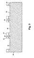
- FIG. 3is the elevation view of FIG. 2 , further showing a first etching step producing trenches in the substrate;
- FIG. 4is the elevation view of FIG. 3 , further showing removal of a masking material and depositing a sacrificial material in the trenches;
- FIG. 5is the elevation view of FIG. 4 , further showing attachment of a piezoelectric layer metallized on both sides adjacent to the filled trenches;
- FIG. 6is the elevation view of FIG. 5 , further showing application of a masking layer on a lower substrate face;
- FIG. 7is the elevation view of FIG. 6 , further showing etching of the lower substrate face and formation of lower channels;
- FIG. 8is the elevation view of FIG. 7 , further showing micro-machined channels from the lower substrate face to a depth of the sacrificial material;
- FIG. 9is the elevation view of FIG. 8 , further showing attachment of a flexible sheath having electrically conductive traces disposed on it;
- FIG. 10is the elevation view of FIG. 9 , further showing multiple cuts through the piezoelectric beam layer;
- FIG. 11is the elevation view of FIG. 10 , further showing a mirror image element assembly attached at each outwardly exposed piezoelectric beam layer of the FIG. 10 initial assembly;
- FIG. 12is a perspective view of a partial unit cell of the present invention showing a perforated upper and lower sheath;
- FIG. 13is a perspective view of an alternate preferred embodiment of the present invention having vertically disposed MEMS members
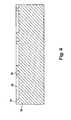
- FIG. 14is an elevation view of a mold insert having an embossed or injected plastic sacrificial replica mold thereon;
- FIG. 15is an elevation view of the plastic sacrificial replica mold of FIG. 14 , showing the mold cavities filled with a ceramic piezoelectric slurry to form piezoceramic beams, and a separate ceramic body attached to exposed surfaces of the piezoceramic beams with conductive traces present at the base of the beams;
- FIG. 16is the rotated elevation view of FIG. 15 after removal of the plastic molded material by a heat/curing process, showing a plurality of vertical piezoceramic beams;
- FIG. 17is the elevation view of FIG. 16 , further showing a photo-imageable layer molded over the vertical beams of FIG. 16 ;
- FIG. 18is the elevation view of FIG. 17 showing a plurality of recesses formed after an aligned x-ray exposure photolithographic process with a plurality of electrical contacts at the base of the beams used for metal plating;
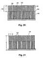
- FIG. 19is the elevation view of FIG. 18 , further showing a metal filler material plated within the recesses evacuated by the photolithographic step shown in FIG. 18 ;
- FIG. 20is the elevation view of FIG. 19 , further showing a spin coated, metal-filled x-ray resist on top of the substrate which forms the cantilevered mass;
- FIG. 21is an elevation view showing a portion of a unit cell of vertical elements of the present invention, following etching to remove all plastic material.
- Partial unit cell 10comprises a plurality of piezoelectric cantilevered beams 12 .
- an intermediate upper column 14 and an intermediate lower column 16are provided.
- an upper cantilevered mass 18 and a lower cantilevered mass 20are provided.
- the upper and lower cantilevered masses 18 and 20are provided to lower the resonant mode of the relatively short and stiff piezoelectric cantilevered beam 12 .
- each of the intermediate columns 14 and 16are attached to a flexible, electrically conductive sheath.
- the intermediate lower column 16is attached to a lower sheath 24 by electrically conductive adhesive 22 .
- the intermediate upper column 14is supported to an upper sheath (not shown) by the electrically conductive adhesive 26 .
- a substrate 30 from which an individual group of MEMS elements 28 are formedis shown in the initial stage of construction.
- the substrate 30is preferably made from one of the refractory metals such as tungsten, molybdenum, tantalum, or titanium.
- the substrate 30is provided with a photo-resist masking pattern 32 which is subsequently used in a photolithography process to trench the substrate upper surface 34 .
- the photo-resist masking pattern 32is attached as known in the art and will not be discussed further herein.
- a plurality of individual trenches 36is shown, which are etched in the substrate 30 by a photolithography process.
- the photo-resist masking pattern 32provides the outer boundaries of each trench 36 .
- the photo-resist masking pattern 32 from FIG. 3is removed and a sacrificial material 38 is filled into each of the previously etched trenches 36 .
- the sacrificial material 38is filled up to the level of the substrate upper surface 34 of substrate 30 as shown.
- the sacrificial material 38is typically an aluminum material but may comprise other metals or other materials as desired.
- a piezoelectric wafer 40is attached to substrate 30 at the substrate upper surface 34 .
- the piezoelectric wafer 40is attached to the substrate 30 following a suitable metallization deposit (not shown) between the substrate upper surface 34 and the piezoelectric wafer 40 as known in the art.
- the piezoelectric wafer 40comprises a central layer of a piezoelectric material 42 surrounded by individual layers of metallization film including a lower metallization film 44 and an upper metallization film 46 .
- the piezoelectric material 42preferably is a piezoelectric material with a high coupling factor, such as lead-magnesium-niobium-titanate (PMNT).
- the lower metallization film 44 and the upper metallization film 46are preferably comprised of an electrically conductive solder-type material. By heating the metallization deposit on the substrate upper surface 34 and the lower metallization film 44 of the piezoelectric wafer 40 , the connection between the piezoelectric wafer 40 and the substrate 30 is made.
- the lower metallization film 44can also be a conductive epoxy.
- the piezoelectric material 42Prior to applying metallization layers on the piezoelectric material 42 , the piezoelectric material 42 is first poled. Poling is a process known in the art which applies a very high value electric field together with elevated temperature to align the molecules in a single direction in the piezoelectric material 42 . Poling is preferably performed prior to bonding the piezoelectric material 42 because the poling process requires the addition of heat (approximately 600° C. for ceramic piezoelectrics) which is undesirable after the piezoelectric wafer 40 is formed. Subsequent deflection of piezoelectric material 42 creates a positive-to-negative charge separation distance which creates a voltage or potential between any two points of the material. This voltage is extracted as current by connecting the material through a resistor or electrical load device. The voltage and therefore the current produced is proportional to the amount of pressure/bending applied to the piezoelectric material 42 .
- a further photolithographic processis performed by first applying a photo-resist masking pattern 48 on a substrate lower surface 50 of the substrate 30 . Similar to the process of FIG. 2 , the process initiated in the step shown by FIG. 6 is used to etch trenches (see FIG. 7 ) in each of the sections between the raised features of the masking pattern 48 .
- a plurality of trenches 52is shown following etching between the raised features of the photo-resist masking pattern 48 attached to the substrate 30 .
- each portion of the photo-resist masking pattern 48 shown in FIG. 7is removed to expose the substrate lower surface 50 .
- a micromachining processis performed in each of the micro-machined areas designated with arrow B to remove material to a depth of, but not including the areas of the sacrificial material 38 .
- individual intermediate columnsare formed.
- a first intermediate column 54 , a second intermediate column 56 and a third intermediate column 58are formed by this micro-machining process.
- a group of weighted massesis also formed.
- a first weighted mass 60 , a second weighted mass 62 and a third weighted mass 64are shown.
- FIG. 8shows only three exemplary intermediate columns and three exemplary weighted masses, however a plurality of such columns and masses are constructed to form a unit cell.
- Each of the intermediate columns 54 , 56 , and 58 , as well as each of the weighted masses 60 , 62 and 64are comprised of the material of the substrate 30 .
- the sacrificial material 38is retained in the step shown in FIG. 8 to protectively support each of the structures shown prior to completion of the attachment and micro-machining processes.
- the resulting structure shown in FIG. 8is attached to a conductive sheath 66 at distal ends of each of the intermediate columns.
- the first intermediate column 54is joined to the conductive sheath 66 via a first conductive adhesive area 68 .
- the second intermediate column 56is joined to the conductive sheath 58 via a second conductive adhesive area 70 .
- the third intermediate column 58is joined to the conductive sheath 66 via a third conductive adhesive area 72 .
- the conductive adhesive used to join the intermediate columns to the conductive sheath 66is preferably an electrically conductive epoxy material, which is selected to provide sufficient stiffness to transfer the vibration energy of the vibration source (not shown) through the conductive sheath 66 to each intermediate column with low energy loss and small frequency change.
- a micro-machining stepis next performed.
- Micro-machined (cut) areas identified by arrows Care shown between each successive weighted mass and its adjacent intermediate column.
- the portion of the sacrificial material 38 which is immediately below the section of the piezoelectric wafer 40 prior to this step (see FIG. 9 )is also removed by this micro-machining process.
- Each micro-machining cutis preferably performed using either a laser machining or a semi-conductor wafer saw process to separate the piezoelectric wafer 40 into individual cantilevered beams.
- a first cantilevered beam 74 , a second cantilevered beam 76 and a third cantilevered beam 78are shown in FIG. 10 following the removal of material by the micro-machining process.
- the sacrificial material 38is retained in the step shown in FIG. 10 in order to retain the structural rigidity between each of the weighted masses 60 , 62 and 64 and the underside of each of the cantilevered beams 74 , 76 and 78 respectively. These layers of the sacrificial material 38 are removed in a later step.
- the partial unit cell 86is constructed by using an initial sub-assembly 88 provided by the step of FIG. 10 and adding to this a mirror image sub-assembly 90 which is the mirror image of the initial sub-assembly 88 .
- the mirror image sub-assembly 90is constructed using the same techniques and steps as that for the initial sub-assembly 88 and is therefore not described in detail herein.
- conductive metallization layersare shown in exaggerated thickness between each of the cantilevered beam pairs.
- a conductive sheath 92forms an upper surface for the partial unit cell 86
- the conductive sheath 66forms a lower surface for the partial unit cell 86 .
- the initial sub-assembly 88 and the mirror image sub-assembly 90are joined at the junction between cantilevered beams. As shown in FIG. 11 , the first cantilevered beam 74 of the initial subassembly 88 is joined to a fourth cantilevered beam 94 through a first conductive metallization layer 80 .
- the second cantilevered beam 76is joined to a fifth cantilevered beam 96 through a second conductive metallization layer 82 .
- the third cantilevered beam 78is similarly joined to a sixth cantilevered beam 98 through a third conductive metallization layer 84 .
- a heating process known in the art as solder-reflowis applied to physically join the initial sub-assembly 88 to the mirror image sub-assembly 90 via the conductive metallization layers 80 , 82 , and 84 respectively.
- the remaining sacrificial material 38(previously retained in FIG. 10 ), is removed from each of the spaces adjacent to each cantilevered beam and its associated weighted mass, i.e., in the areas identified as material removal areas D.
- the sacrificial material 38is removed by an etching process.
- An outer facing surface of either the conductive sheath 66 or the conductive sheath 92can be joined to a vibrating structure or body (not shown) through the use of a suitable adhesive or other joining method.
- the partial unit cell 86is flexible to allow the conductive sheath 66 or the conductive sheath 92 which is attached to the vibrating body to conform to either a generally flat or a moderating surface of the body.
- Electrical current generated by any of the cantilevered beamsis passed via its associated intermediate column through its connecting adhesive area to its associated conductive sheath. Electrical current is collected from both the conductive sheath 66 and the conductive sheath 92 .
- FIG. 12a perspective, cut-away view of a unit cell 100 is shown.
- the conductive sheath 66 and the conductive sheath 92 of the unit cell 100are also shown.
- a plurality of apertures 102are formed in each of the conductive sheaths 66 and 92 .
- the apertures 102are optionally provided for an etching solution to remove the sacrificial material remaining on any portions of the unit cell 100 .
- FIG. 12also shows a continuous intermediate column 104 that is preferably used in place of individual intermediate columns (e.g., intermediate column 16 of FIG. 1 ) for a more efficient structural joining of a plurality of elements of the unit cell 100 .
- a typical mass to mass spacing identified by arrows Eis shown.
- each of the joined pairs of cantilevered beamsform a bimorph beam 106 .
- the bimorph beam 106 constructionprovides a double layer of piezoelectric material. Each layer half has an oppositely polarized surface. By bending the bimorph beam 106 in either direction (as indicated by arrow A in FIG. 1 ), an electrical current is generated.
- FIG. 13shows a portion of a vertical element unit cell 200 .
- Each vertical element 202 of the vertical element unit cell 200is comprised of a vertical bimorph beam 204 and a unitary mass 206 .
- a single sheath 208 having conductive tracesis used for the vertical element unit cell 200 .
- the single sheath 208is attached to the vibrating body inducing each of the vertical bimorph beams 204 to vibrate.
- Bi-directional motion indicated by arrows Gis provided for each of the unitary masses 206 .
- Each unitary mass 206therefore forms the deflection limit for each successive vertical element 202 .
- each vertical bimorph beam 204is electrically joined to the conductive traces of the single sheath 208 by construction as will be further elucidated with reference to FIGS. 14 to 19 .
- the process for forming the vertical element unit cell 200differs from the process used to form the horizontal unit cell 100 of FIG. 12 .
- the following stepsare used to form the vertical element unit cell 200 .
- a permanent mold insert 210preferably constructed of nickel, is used as the receiving mold to develop a plastic sacrificial replica mold 212 having individual vertical beams. Alternate materials can also be used for the permanent mold insert 210 . Either an embossing or an injection molding technique is used to prepare the plastic sacrificial replica mold 212 using the permanent mold insert 210 .
- the material for the plastic sacrificial replica mold 212is preferably polymethylmethacrylate (PMMA) due to the material's photoimaging properties using an electron beam, X-rays, or ultraviolet light. Other materials can be used for the plastic sacrificial replica mold 212 .
- PMMApolymethylmethacrylate
- the plastic sacrificial replica mold 212is shown following removal from the permanent mold insert 210 .
- a slurry of piezoceramic material 214is poured into each of the cavities of the plastic sacrificial replica mold 212 .
- the top surfaces of each of the filled cavities of the plastic sacrificial replica mold 212are polished after the piezoceramic material 214 solidifies.
- a plurality of metal conductive layers 215is then deposited through a mask (not shown) to the polished surfaces of the piezoceramic material 214 . Since the deposition of a metal conductive layer is known in the art, it is not detailed herein.
- the material for the metal conductive layeris preferably a gold or gold containing material deposited using an evaporative or a sputtering step also known in the art.
- a wafer 216 of ceramic or alternately of quartz materialis then attached using a thin layer of a high temperature adhesive (not shown) to the polished surfaces of the plastic sacrificial replica mold 212 and the piezoceramic material 214 .
- the piezoceramic material 214does not adhere to the material of the plastic sacrificial replica mold 212 .
- the sub-assemblyis heat cured which removes the plastic material, i.e., the plastic sacrificial replica mold 212 shown in FIG. 15 .
- the remaining material following this heat curing processis the arrangement shown in FIG. 16 having the wafer 216 rotated 180° from the orientation shown in FIG. 15 , thus showing the vertical piezoceramic beams 218 in an upward facing direction as viewed in FIG. 16 .
- a photo-imageable layer 220is applied over the vertical piezoceramic beams 218 .
- This photo-imageable layer 220surrounds each of the vertical piezoceramic beams 218 and contacts the piezoceramic wafer 216 .
- the photo-imageable layer 220can advantageously be applied up to a thickness of about 1 to 2 millimeters.
- Material for the photo-imageable layer 220is preferably a PMMA material.
- the remaining photo-imageable layer 220 from FIG. 17is shown after the top surfaces of each of the vertical piezoceramic beams 218 has been planarized to remove the excess photo-imageable layer 220 material.
- the excess materialis removed to form a surface 222 indicated by arrow 1 .
- an aligned x-ray exposureis also performed to create a plurality of exposure recesses 224 down to a wafer surface 226 of the wafer 216 (installed in the step shown in FIG. 15 ).
- the exposure recesses 224 of FIG. 18are filled with an electrically conductive plating material 228 from each of the electrical contacts 215 up to the surface 222 of each of the vertical piezoceramic beams 218 .
- Material for the electrically conductive plating material 228is selected from materials including nickel, copper, gold, and other electrically conductive materials. This is followed by a flood exposure step for the later removal of the resist pattern used for plating.
- a metal filled, negative x-ray resist 230is spin coated on the surface 222 to a predetermined height J.
- the predetermined height Jis determined by at least one of the following: 1) the natural frequency modes of the vibrating body to which the vertical element unit cell or array is attached; 2) the number of elements of the vertical element unit cell; 3) the amount of electrical current desired; 4) the material/density of the mass elements; 5) the type of piezoelectric material used; and 6) the length of the piezoceramic cantilevered beams.
- a plastic materialis used for the negative x-ray resist 230 .
- the plastic materialshould be a solvent-free plastic, such as epoxy, such that contact with the negative x-ray resist 230 will not effect the PMMA material of the photo imageable layer 220 remaining in the structure during this step.
- a photo-lithographic stepis then performed to remove material from the negative x-ray resist 230 , leaving open areas 232 to form a plurality of vertical unitary masses 234 .
- Material for the vertical unitary masses 234can be of metal, high density plastic, ceramic, or other material having a density suitable as a weighted mass.
- a total vertical element height Kranges from about 0.1 mm to about 2.0 mm.
- the vertical element mass width Lranges from about 0.1 mm to about 2.0 mm.
- an insulating layer (not shown) of a non-electrically conductive materialis deposited between each vertical unitary mass 234 and each vertical piezoceramic beam 218 .
- a protective covercan be used to prevent foreign material from entering between individual elements and to prevent physical damage to the exposed elements.
- the advantage of the vertical element designis that a greater number of elements per square unit area is obtainable, therefore a potentially greater electrical current can be generated.
- MEMS devicesare generally constructed of micro-machined silicon.
- a refractory metalsuch as tungsten, molybdenum, tantalum, or titanium is preferably used for construction of the element bodies. These materials provide better stiffness and much higher densities and thus are more suitable as proof mass material.
- the piezoelectric MEMS devices of the present inventioncan be used as an electrical current source and attached to vibration sources which vary significantly. Examples of such vibration sources are any moving vehicle, i.e., automobiles, aircraft, military craft and spacecraft.
- the devices of the present inventioncan also be used on a wide variety of other applications, such as being attached to clothing for generation of a small electrical power for hand-held electrical devices such as telephones.
- Another useful adaptation for the devices of the present inventionis as a power source for remote sensing equipment.
- Known sensing equipment used for remote sensing devicestypically use batteries or other electrical power generation sources such as chemical reactions.
- the piezoelectric devices of the present inventioncan be used to replace the battery or other power sources for remote sensor applications.
- the bimorph configuration of the piezoelectric materials of the present inventionis a preferred embodiment of the present invention. Poling of the piezoelectric material is preferably conducted prior to joining the two layers of material together to form the bimorph due to the elevated temperature of the poling process. The material is poled perpendicular to its thickness. The resulting piezoelectric material has a metallic contact plated on either side of the material to collect the electrical current.
- the piezoelectric devices of the present inventionoffer several advantages. By configuring the devices into unit cells of varying numbers of elements, and with the ability to employ multiple unit cells in an array, a wide variety of electrical currents for varying power sources can be derived.
- the piezoelectric devices of the present inventionare capable of being employed on flat or on varying geometry surfaces. These devices are relatively unaffected within a temperature range of about ⁇ 60° centigrade to about 200° centigrade.
- the piezoelectric devices of the present inventionalso can operate essentially maintenance free for a significant period of time, i.e., several decades. There is no fuel source and there are no moving parts other than the degree of motion required for the cantilevered beams.
- the devicesare pre-tuned based on the natural frequency modes of the item to which they are attached, such that spacing between each weighted mass of the elements of the device can be predetermined to preclude damaging the piezoelectric materials by overextension.
- the piezoelectric devices of the present inventionwill generate electrical current in the milliwatt range compared to devices known in the art which produce current in the microwatt or nanowatt ranges.
Landscapes
- General Electrical Machinery Utilizing Piezoelectricity, Electrostriction Or Magnetostriction (AREA)
- Transducers For Ultrasonic Waves (AREA)
Abstract
Description
The present invention relates generally to piezoelectric devices which generate electrical energy by induced vibration and more specifically to an apparatus and method to utilize a thin, conformable sheet, having a plurality of piezobimorph cantilevered beams to produce electrical energy.
Moving objects or platforms generate vibration energy which is commonly steady in amplitude or that increases with age of the object or platform. All platforms suffer material degradation over time due to this continuous vibration, and for this reason system inspections are periodically performed or sensors are installed to monitor strain levels in such structures to help predict material failure. Common remotely addressable sensor devices require a power level in the milliwatt (mW) range. Batteries or other fuel sources can power such sensing devices. These power sources have drawbacks in that they require frequent maintenance or replacement, and in many instances may be located in difficult to reach locations in a platform. In addition, they deliver inadequate power levels and often fail at low temperature extremes.
Devices which generate mechanical or electrical power by the vibration of the item to which they are attached are known. In an exemplary application, the proof mass used in automatic wrist watches, i.e., the self-winding wrist watches, either rotates or moves in one direction due to the movement of the wearer's wrist. This type of device produces energy in very low quantities, typically in the micro-watt range, sufficient to power the wrist watch. Based on its low power output and form factor, this type of device is not desirable for a power source for remote sensing devices required on applications for moving platforms such as aircraft. Further, this type of proof mass system is more suitable for impulse movements as opposed to continuous vibration movements. In addition, a further drawback of the proof mass type system of power generation is the size of the proof mass is typically impractical for use on most embedded sensor systems.
Materials which can be attached to a vibration source and which generate an electrical current from the vibrations are known. Piezoelectric materials are examples of these materials, and are well known in the art. These materials generate small electrical currents when the material is deflected, for example by vibrations. A piezoelectric device which is small in size and advantageously utilizes the vibration energy of the platform as a power source is desirable. The use of very small devices such as micro-electro-mechanical systems (MEMS) is known in the art to generate power. However, they are either impractical due to the low power generated (i.e., typically in the microwatt range or as low as the nanowatt range) or unreliable compared with piezoelectric devices.
Piezoelectric crystal systems harvesting energy from the motion of humans or animals are also known. This type of a device is disclosed in U.S. Pat. No. 3,456,134 issued to Kuo. Although the energy harvested by such a device may be adequate for remote sensing applications, it is macroscopic in size, measured in inches, which is undesirable for, most embedded sensing systems.
The improvement using a piezoelectric bimorph beam to harvest vibration energy is also known. A bimorph beam is herein defined as a mirror image double layer of piezoelectric material arranged in beam formation. A bimorph beam is created by joining two oppositely polarized piezoelectric materials in a face-to-face configuration such that deflecting or bending the bimorph structure in one direction creates an electrical potential, and bending the structure in the opposite direction creates an equivalent electrical potential. The bimorph structure therefore produces electric current when deflected in either of two directions. However, most known bimorph piezoelectric beam configurations to date have been on larger size beam configurations, and thus cannot be deployed in a thin conformal layer that can be attached to an arbitrarily shaped structure without adding significant weight or volume.
An improvement is therefore desirable for piezoelectric material bimorph systems such that the resulting configuration is able to produce reasonably high current levels, while at the same time can provide a piezoelectric bimorph beam system which provides a degree of flexibility or conformability such that the material can be applied over a variety of surface areas, i.e. flat as well as curving surface areas. Also, past implementation of piezoelectric beams either have not had adequate protection so that the beam does not break or get damaged over a very long time period (tens of years) in a very harsh environment (e.g., aerospace) or they have had rather bulky and impractical protective packages.
According to the principles of the present invention, large arrays of MEMS devices having weighted, cantilevered, piezoelectric beams in a bimorph configuration, oscillate and produce electrical current from vibrations of the surface to which they are attached. The piezoelectric power source of the present invention can be integrated in a variety of applications, including wireless sensor modules. The power devices of the present invention are capable of operation as part of a stand-alone unit that can last for the lifetime of a system, a time span measured in decades. The magnitude of energy needed for exemplary wireless sensor applications require a generation rate of milliwatts of power. This is achieved in the present invention by maximizing the amount of energy each MEMS element generates and by using a large array of elements.
The power source devices of the present invention are made of the following parts: (1) an element—a weighted, cantilevered MEMS piezoelectric bimorph beam; (2) a unit cell—a collection of MEMS elements in a form of about 1 centimeter squared (cm2) in area and about 0.5 millimeters (mm) thick, having about 150 to about 200 elements; (3) an array—the collection of many unit cells, typically about 100, all interconnected electrically to form a power generation unit; and (4) a protective sheath—a partially flexible electrically conductive material which forms a protective envelope for the unit cells on at least one element side and which provides the interconnection pathways between each element and the array. The sheath in one embodiment also provides a boundary limit, so that each piezobimorph element beam cannot overextend under impulse conditions, which could result in fracture. The sheath is preferably perforated, but can also be totally solid for some applications. The sheath is preferably flexible to permit an array to be connected over a flat or a contoured surface. The use of the sheath also allows for the array of MEMS piezoelectric bimorph beams to couple to longer wavelength harmonic vibrations of the structure, in a collective mode pattern, due the fact that all the elements of the array are mechanically joined to the sheath on one end.
In one preferred embodiment of the present invention, a bimorph piezoelectric device is provided, comprising a plurality of micro-electro-mechanical-system (MEMS) piezoelectric beams. The plurality of MEMS beams is arranged as pairs of MEMS beams, each pair having a connecting end and a weighted end. Each of said pairs of MEMS beams is electrically and mechanically joined through its connecting end to at least one flexible electrically conductive sheath, to form a joined array of MEMS beams, each having its weighted end free to deflect. Each weighted end of said pairs of MEMS beams of said joined array is deflectable to produce an electric current proportional to a quantity of said pairs of MEMS beams, said electric current is collectable from each of said at least one electrically conductive sheath.
In another preferred embodiment of the present invention, a piezoelectric device for converting vibration energy to electric current is provided, comprising a plurality of pairs of oppositely polarized piezoelectric wafers deflectable to produce an electrical current. The plurality of pairs of wafers are each connected to a set of micro-machined elements. Each said set of elements with said pairs of wafers form a bimorph, said bimorph being configured as a cantilevered beam. Each said cantilevered beam is mass weighted on a first beam end, and fixedly attached to at least one protective sheath on a second beam end. A plurality of said bimorphs on said at least one protective sheath form an array.
In yet another preferred embodiment of the present invention, a method for forming a horizontally configured piezoelectric electrical current generating device is provided, which comprises the steps of: (I) creating an initial sub-assembly by: (1) joining a piezoelectric material plate to an upper surface of a substrate; (2) micromachining a lower surface of said substrate to both form a plurality of masses supported by said piezoelectric material plates and retain a plurality of non-machined lower surface areas; (3) electrically bonding said plurality of non-machined lower surface areas to an electrically conductive protective sheath; and (4) cutting through said piezoelectric material to separate a plurality of individual cantilevered piezoelectric material beam lengths; and (II) constructing a mirror-image sub-assembly to said initial subassembly; and (III) connecting said mirror image sub-assembly to said initial subassembly.
In still another preferred embodiment of the invention, a method for forming a vertically configured piezoelectric electrical current generating device is provided, which comprises the steps of: (1) filling until dry a sacrificial plastic replica mold with a ceramic piezoelectric slurry to form a piezoceramic green body; (2) bonding a substrate to said piezoceramic green body; (3) heat curing the substrate and piezoceramic green body to both remove said plastic mold and expose a plurality of piezoceramic vertical beams; (4) casting a resist over said beams along a top surface thereof; (5) aligning an X-ray exposure to create a plurality of recesses for an electrode structure and. plating a metal in the recesses to metallize the piezoelectric beams; (6) flood exposing a remaining portion of said vertical beams; (7) spin-coating a thin negative resist layer for electrical isolation between the piezoelectric beams and the metallic proof mass and spin-coating a metal filled, negative X-ray resist on the top surface to provide a cantilevered proof mass; (8) performing a second aligned X-ray exposure to separate said cantilevered mass into a plurality of cantilevered masses; and (9) stripping both a remaining portion of said negative resist and said flood exposed resist to form a plurality of said cantilevered piezoceramic vertical beams, each having one of said plurality of cantilevered masses.
Further areas of applicability of the present invention will become apparent from the detailed description provided hereinafter. It should be understood that the detailed description and specific examples, while indicating the preferred embodiment of the invention, are intended for purposes of illustration only and are not intended to limit the scope of the invention.
The present invention will become more fully understood from the detailed description and the accompanying drawings, wherein:
The following description of the preferred embodiment(s) is merely exemplary in nature and is in no way intended to limit the invention, its application, or uses.
Referring toFIG. 1 , a MEMSpartial unit cell 10 is shown.Partial unit cell 10 comprises a plurality of piezoelectric cantilevered beams12. At a fixed or support end of each of the piezoelectric cantilevered beams12, an intermediateupper column 14 and an intermediatelower column 16 are provided. At a distal end of each piezoelectric cantileveredbeam 12, an upper cantileveredmass 18 and a lowercantilevered mass 20 are provided. The upper and lower cantileveredmasses cantilevered beam 12.
When attached to a vibrating structure or item, thepartial unit cell 10 will vibrate in response to the vibration source. The upper cantileveredmass 18 and the lower cantileveredmass 20 will deflect in the mass direction of motion arrows A as shown. For a horizontal element configuration shown inFIG. 1 , each of theintermediate columns lower column 16 is attached to alower sheath 24 by electricallyconductive adhesive 22. Similarly, the intermediateupper column 14 is supported to an upper sheath (not shown) by the electricallyconductive adhesive 26. Current generated by any of the individual piezoelectric cantilevered beams12 is transferred via each intermediateupper column 14 and the intermediatelower column 16 to either thelower sheath 24 or the upper sheath (not shown). A plurality ofMEMS elements 28 will make up a cell unit.
Referring now toFIG. 2 , asubstrate 30 from which an individual group ofMEMS elements 28 are formed is shown in the initial stage of construction. Thesubstrate 30 is preferably made from one of the refractory metals such as tungsten, molybdenum, tantalum, or titanium. At this initial step, thesubstrate 30 is provided with a photo-resistmasking pattern 32 which is subsequently used in a photolithography process to trench the substrateupper surface 34. The photo-resistmasking pattern 32 is attached as known in the art and will not be discussed further herein.
Referring toFIG. 3 , a plurality ofindividual trenches 36 is shown, which are etched in thesubstrate 30 by a photolithography process. The photo-resistmasking pattern 32 provides the outer boundaries of eachtrench 36.
Referring toFIG. 4 , the photo-resistmasking pattern 32 fromFIG. 3 is removed and asacrificial material 38 is filled into each of the previously etchedtrenches 36. Thesacrificial material 38 is filled up to the level of the substrateupper surface 34 ofsubstrate 30 as shown. Thesacrificial material 38 is typically an aluminum material but may comprise other metals or other materials as desired.
Referring now toFIG. 5 , following addition of thesacrificial material 38, apiezoelectric wafer 40 is attached tosubstrate 30 at the substrateupper surface 34. Thepiezoelectric wafer 40 is attached to thesubstrate 30 following a suitable metallization deposit (not shown) between the substrateupper surface 34 and thepiezoelectric wafer 40 as known in the art.
Thepiezoelectric wafer 40 comprises a central layer of apiezoelectric material 42 surrounded by individual layers of metallization film including alower metallization film 44 and anupper metallization film 46. Thepiezoelectric material 42 preferably is a piezoelectric material with a high coupling factor, such as lead-magnesium-niobium-titanate (PMNT). Thelower metallization film 44 and theupper metallization film 46 are preferably comprised of an electrically conductive solder-type material. By heating the metallization deposit on the substrateupper surface 34 and thelower metallization film 44 of thepiezoelectric wafer 40, the connection between thepiezoelectric wafer 40 and thesubstrate 30 is made. Thelower metallization film 44 can also be a conductive epoxy.
Prior to applying metallization layers on thepiezoelectric material 42, thepiezoelectric material 42 is first poled. Poling is a process known in the art which applies a very high value electric field together with elevated temperature to align the molecules in a single direction in thepiezoelectric material 42. Poling is preferably performed prior to bonding thepiezoelectric material 42 because the poling process requires the addition of heat (approximately 600° C. for ceramic piezoelectrics) which is undesirable after thepiezoelectric wafer 40 is formed. Subsequent deflection ofpiezoelectric material 42 creates a positive-to-negative charge separation distance which creates a voltage or potential between any two points of the material. This voltage is extracted as current by connecting the material through a resistor or electrical load device. The voltage and therefore the current produced is proportional to the amount of pressure/bending applied to thepiezoelectric material 42.
Referring now toFIG. 6 , a further photolithographic process is performed by first applying a photo-resistmasking pattern 48 on a substratelower surface 50 of thesubstrate 30. Similar to the process ofFIG. 2 , the process initiated in the step shown byFIG. 6 is used to etch trenches (seeFIG. 7 ) in each of the sections between the raised features of themasking pattern 48.
Referring now toFIG. 7 , a plurality oftrenches 52 is shown following etching between the raised features of the photo-resistmasking pattern 48 attached to thesubstrate 30.
Referring now toFIG. 8 , each portion of the photo-resistmasking pattern 48 shown inFIG. 7 is removed to expose the substratelower surface 50. A micromachining process is performed in each of the micro-machined areas designated with arrow B to remove material to a depth of, but not including the areas of thesacrificial material 38. By removing material in the micro-machined areas B, individual intermediate columns are formed. A firstintermediate column 54, a secondintermediate column 56 and a thirdintermediate column 58 are formed by this micro-machining process. In addition to theintermediate columns weighted mass 60, a secondweighted mass 62 and a thirdweighted mass 64 are shown. For clarity,FIG. 8 shows only three exemplary intermediate columns and three exemplary weighted masses, however a plurality of such columns and masses are constructed to form a unit cell. Each of theintermediate columns weighted masses substrate 30. Thesacrificial material 38 is retained in the step shown inFIG. 8 to protectively support each of the structures shown prior to completion of the attachment and micro-machining processes.
Referring now toFIG. 9 , the resulting structure shown inFIG. 8 is attached to aconductive sheath 66 at distal ends of each of the intermediate columns. The firstintermediate column 54 is joined to theconductive sheath 66 via a firstconductive adhesive area 68. The secondintermediate column 56 is joined to theconductive sheath 58 via a secondconductive adhesive area 70. The thirdintermediate column 58 is joined to theconductive sheath 66 via a third conductiveadhesive area 72. The conductive adhesive used to join the intermediate columns to theconductive sheath 66 is preferably an electrically conductive epoxy material, which is selected to provide sufficient stiffness to transfer the vibration energy of the vibration source (not shown) through theconductive sheath 66 to each intermediate column with low energy loss and small frequency change.
Referring toFIG. 10 , a micro-machining step is next performed. Micro-machined (cut) areas identified by arrows C are shown between each successive weighted mass and its adjacent intermediate column. The portion of thesacrificial material 38 which is immediately below the section of thepiezoelectric wafer 40 prior to this step (seeFIG. 9 ) is also removed by this micro-machining process. Each micro-machining cut is preferably performed using either a laser machining or a semi-conductor wafer saw process to separate thepiezoelectric wafer 40 into individual cantilevered beams. A first cantileveredbeam 74, a secondcantilevered beam 76 and a thirdcantilevered beam 78 are shown inFIG. 10 following the removal of material by the micro-machining process. Note that thesacrificial material 38 is retained in the step shown inFIG. 10 in order to retain the structural rigidity between each of theweighted masses sacrificial material 38 are removed in a later step.
Referring now toFIG. 11 , apartial unit cell 86 is shown. Thepartial unit cell 86 is constructed by using aninitial sub-assembly 88 provided by the step of FIG.10 and adding to this amirror image sub-assembly 90 which is the mirror image of theinitial sub-assembly 88. Themirror image sub-assembly 90 is constructed using the same techniques and steps as that for theinitial sub-assembly 88 and is therefore not described in detail herein. As described below, conductive metallization layers (similar to those applied in the step described inFIG. 5 ) are shown in exaggerated thickness between each of the cantilevered beam pairs.
Aconductive sheath 92 forms an upper surface for thepartial unit cell 86, and theconductive sheath 66 forms a lower surface for thepartial unit cell 86. Theinitial sub-assembly 88 and themirror image sub-assembly 90 are joined at the junction between cantilevered beams. As shown inFIG. 11 , the firstcantilevered beam 74 of theinitial subassembly 88 is joined to a fourthcantilevered beam 94 through a first conductive metallization layer80. The secondcantilevered beam 76 is joined to a fifthcantilevered beam 96 through a second conductive metallization layer82. The thirdcantilevered beam 78 is similarly joined to a sixthcantilevered beam 98 through a thirdconductive metallization layer 84. After alignment of each of the paired cantilevered beams, a heating process known in the art as solder-reflow is applied to physically join theinitial sub-assembly 88 to themirror image sub-assembly 90 via the conductive metallization layers80,82, and84 respectively.
Following the step of joining each of the groups of cantilevered beams, the remaining sacrificial material38 (previously retained in FIG.10), is removed from each of the spaces adjacent to each cantilevered beam and its associated weighted mass, i.e., in the areas identified as material removal areas D. Thesacrificial material 38 is removed by an etching process. An outer facing surface of either theconductive sheath 66 or theconductive sheath 92 can be joined to a vibrating structure or body (not shown) through the use of a suitable adhesive or other joining method. Thepartial unit cell 86 is flexible to allow theconductive sheath 66 or theconductive sheath 92 which is attached to the vibrating body to conform to either a generally flat or a moderating surface of the body.
Electrical current generated by any of the cantilevered beams is passed via its associated intermediate column through its connecting adhesive area to its associated conductive sheath. Electrical current is collected from both theconductive sheath 66 and theconductive sheath 92.
Referring toFIG. 12 , a perspective, cut-away view of aunit cell 100 is shown. Theconductive sheath 66 and theconductive sheath 92 of theunit cell 100 are also shown. A plurality ofapertures 102 are formed in each of theconductive sheaths apertures 102 are optionally provided for an etching solution to remove the sacrificial material remaining on any portions of theunit cell 100.FIG. 12 also shows a continuousintermediate column 104 that is preferably used in place of individual intermediate columns (e.g.,intermediate column 16 ofFIG. 1 ) for a more efficient structural joining of a plurality of elements of theunit cell 100. A typical mass to mass spacing identified by arrows E is shown. The mass to mass spacing ranges from about several micrometers to about 100 micrometers. A typical mass to column spacing identified by arrows F is also shown. The typical mass to column spacing also ranges from about several micrometers to about 50 micrometers. Following element assembly as shown inFIG. 12 , each of the joined pairs of cantilevered beams form abimorph beam 106. Thebimorph beam 106 construction provides a double layer of piezoelectric material. Each layer half has an oppositely polarized surface. By bending thebimorph beam 106 in either direction (as indicated by arrow A in FIG.1), an electrical current is generated.
Referring now toFIG. 13 , another preferred embodiment of the present invention is shown.FIG. 13 shows a portion of a verticalelement unit cell 200. Eachvertical element 202 of the verticalelement unit cell 200 is comprised of avertical bimorph beam 204 and aunitary mass 206. For the verticalelement unit cell 200, asingle sheath 208 having conductive traces is used. Thesingle sheath 208 is attached to the vibrating body inducing each of the vertical bimorph beams204 to vibrate. Bi-directional motion indicated by arrows G is provided for each of theunitary masses 206. Eachunitary mass 206 therefore forms the deflection limit for each successivevertical element 202. Vertical mass to vertical mass spacing identified as arrows H ranges from several micrometers to about 200 micrometers. The fixed end of eachvertical bimorph beam 204 is electrically joined to the conductive traces of thesingle sheath 208 by construction as will be further elucidated with reference toFIGS. 14 to19.
The process for forming the verticalelement unit cell 200 differs from the process used to form thehorizontal unit cell 100 of FIG.12. The following steps are used to form the verticalelement unit cell 200.
Referring toFIG. 14 , the initial construction stage of a vertical element unit cell is shown. Apermanent mold insert 210, preferably constructed of nickel, is used as the receiving mold to develop a plasticsacrificial replica mold 212 having individual vertical beams. Alternate materials can also be used for thepermanent mold insert 210. Either an embossing or an injection molding technique is used to prepare the plasticsacrificial replica mold 212 using thepermanent mold insert 210. The material for the plasticsacrificial replica mold 212 is preferably polymethylmethacrylate (PMMA) due to the material's photoimaging properties using an electron beam, X-rays, or ultraviolet light. Other materials can be used for the plasticsacrificial replica mold 212.
Referring now toFIG. 15 , the plasticsacrificial replica mold 212 is shown following removal from thepermanent mold insert 210. A slurry ofpiezoceramic material 214 is poured into each of the cavities of the plasticsacrificial replica mold 212. The top surfaces of each of the filled cavities of the plasticsacrificial replica mold 212 are polished after thepiezoceramic material 214 solidifies. A plurality of metalconductive layers 215 is then deposited through a mask (not shown) to the polished surfaces of thepiezoceramic material 214. Since the deposition of a metal conductive layer is known in the art, it is not detailed herein. The material for the metal conductive layer is preferably a gold or gold containing material deposited using an evaporative or a sputtering step also known in the art. Awafer 216 of ceramic or alternately of quartz material is then attached using a thin layer of a high temperature adhesive (not shown) to the polished surfaces of the plasticsacrificial replica mold 212 and thepiezoceramic material 214. Thepiezoceramic material 214 does not adhere to the material of the plasticsacrificial replica mold 212.
Referring toFIG. 16 , following the addition of thewafer 216, as shown inFIG. 15 , the sub-assembly is heat cured which removes the plastic material, i.e., the plasticsacrificial replica mold 212 shown in FIG.15. The remaining material following this heat curing process is the arrangement shown inFIG. 16 having thewafer 216 rotated 180° from the orientation shown inFIG. 15 , thus showing the verticalpiezoceramic beams 218 in an upward facing direction as viewed in FIG.16.
Referring now toFIG. 17 , a photo-imageable layer 220 is applied over the vertical piezoceramic beams218. This photo-imageable layer 220 surrounds each of the verticalpiezoceramic beams 218 and contacts thepiezoceramic wafer 216. The photo-imageable layer 220 can advantageously be applied up to a thickness of about 1 to 2 millimeters. Material for the photo-imageable layer 220 is preferably a PMMA material.
Referring toFIG. 18 , the remaining photo-imageable layer 220 fromFIG. 17 is shown after the top surfaces of each of the verticalpiezoceramic beams 218 has been planarized to remove the excess photo-imageable layer 220 material. The excess material is removed to form asurface 222 indicated byarrow 1. During this step, an aligned x-ray exposure is also performed to create a plurality of exposure recesses224 down to awafer surface 226 of the wafer216 (installed in the step shown in FIG.15).
Referring toFIG. 19 , the exposure recesses224 ofFIG. 18 are filled with an electricallyconductive plating material 228 from each of theelectrical contacts 215 up to thesurface 222 of each of the vertical piezoceramic beams218. Material for the electricallyconductive plating material 228 is selected from materials including nickel, copper, gold, and other electrically conductive materials. This is followed by a flood exposure step for the later removal of the resist pattern used for plating.
Referring toFIG. 20 , a metal filled, negative x-ray resist230 is spin coated on thesurface 222 to a predetermined height J. The predetermined height J is determined by at least one of the following: 1) the natural frequency modes of the vibrating body to which the vertical element unit cell or array is attached; 2) the number of elements of the vertical element unit cell; 3) the amount of electrical current desired; 4) the material/density of the mass elements; 5) the type of piezoelectric material used; and 6) the length of the piezoceramic cantilevered beams. Preferably, a plastic material is used for the negative x-ray resist230. The plastic material should be a solvent-free plastic, such as epoxy, such that contact with the negative x-ray resist230 will not effect the PMMA material of thephoto imageable layer 220 remaining in the structure during this step. A photo-lithographic step is then performed to remove material from the negative x-ray resist230, leavingopen areas 232 to form a plurality of verticalunitary masses 234. Material for the verticalunitary masses 234 can be of metal, high density plastic, ceramic, or other material having a density suitable as a weighted mass.
Referring now toFIG. 21 , the remaining the PMMA material of thephoto imageable layer 220 shown inFIG. 20 is developed and stripped to form the final pattern of apartial unit cell 236 shown. A total vertical element height K ranges from about 0.1 mm to about 2.0 mm. The vertical element mass width L ranges from about 0.1 mm to about 2.0 mm. To avoid electrical shorting between sections of the piezoceramic beam(s) if an electrically conductive material is used for the verticalunitary masses 234, an insulating layer (not shown) of a non-electrically conductive material is deposited between each verticalunitary mass 234 and eachvertical piezoceramic beam 218.
For applications using the vertical element design of the present invention, a protective cover can be used to prevent foreign material from entering between individual elements and to prevent physical damage to the exposed elements. The advantage of the vertical element design is that a greater number of elements per square unit area is obtainable, therefore a potentially greater electrical current can be generated.
Currently, MEMS devices are generally constructed of micro-machined silicon. For the present invention, a refractory metal such as tungsten, molybdenum, tantalum, or titanium is preferably used for construction of the element bodies. These materials provide better stiffness and much higher densities and thus are more suitable as proof mass material.
The piezoelectric MEMS devices of the present invention can be used as an electrical current source and attached to vibration sources which vary significantly. Examples of such vibration sources are any moving vehicle, i.e., automobiles, aircraft, military craft and spacecraft. The devices of the present invention can also be used on a wide variety of other applications, such as being attached to clothing for generation of a small electrical power for hand-held electrical devices such as telephones. Another useful adaptation for the devices of the present invention is as a power source for remote sensing equipment. Known sensing equipment used for remote sensing devices typically use batteries or other electrical power generation sources such as chemical reactions. The piezoelectric devices of the present invention can be used to replace the battery or other power sources for remote sensor applications.
The bimorph configuration of the piezoelectric materials of the present invention is a preferred embodiment of the present invention. Poling of the piezoelectric material is preferably conducted prior to joining the two layers of material together to form the bimorph due to the elevated temperature of the poling process. The material is poled perpendicular to its thickness. The resulting piezoelectric material has a metallic contact plated on either side of the material to collect the electrical current.
The piezoelectric devices of the present invention offer several advantages. By configuring the devices into unit cells of varying numbers of elements, and with the ability to employ multiple unit cells in an array, a wide variety of electrical currents for varying power sources can be derived. The piezoelectric devices of the present invention are capable of being employed on flat or on varying geometry surfaces. These devices are relatively unaffected within a temperature range of about −60° centigrade to about 200° centigrade. The piezoelectric devices of the present invention also can operate essentially maintenance free for a significant period of time, i.e., several decades. There is no fuel source and there are no moving parts other than the degree of motion required for the cantilevered beams. The devices are pre-tuned based on the natural frequency modes of the item to which they are attached, such that spacing between each weighted mass of the elements of the device can be predetermined to preclude damaging the piezoelectric materials by overextension. The piezoelectric devices of the present invention will generate electrical current in the milliwatt range compared to devices known in the art which produce current in the microwatt or nanowatt ranges.
The description of the invention is merely exemplary in nature and, thus, variations that do not depart from the gist of the invention are intended to be within the scope of the invention. Such variations are not to be regarded as a departure from the spirit and scope of the invention.
Claims (34)
1. An energy harvesting device comprising:
a structure having a plurality of discrete resonant frequencies, said structure including:
an essentially annular housing; and
a plurality of inwardly protecting beams; and
a piezoelectric member disposed in vibration receiving relation to said structure.
2. The device ofclaim 1 further comprising:
a circuit electrically communicating with said piezoelectric member.
3. The device ofclaim 1 wherein said plurality of inwardly protecting beams vary in resonant frequencies.
4. The device ofclaim 3 wherein each of said plurality of inwardly protecting beams has a different resonant frequency.
5. The device ofclaim 3 wherein said plurality of inwardly protecting beams vary in at least one of length, mass, and mass distribution.
6. The device ofclaim 3 wherein said plurality of inwardly projecting beams further comprise aluminum.
7. The device ofclaim 6 wherein said aluminum inwardly protecting beams are coated with a non-conductive material.
8. The device ofclaim 1 wherein said device is substantially planar.
9. An energy harvesting device comprising:
a structure having a plurality of discrete resonant frequencies, said structure including:
a central hub; and
a plurality of radially projecting beams; and
a piezoelectric member disposed in vibration receiving relation to said structure.
10. An energy harvesting device comprising:
an essentially annular base;
a plurality of cantilevered beams inwardly extending from said base, said plurality of beams varying in resonant frequencies; and
a piezoelectric member coupled to said plurality of beams in a vibration receiving relationship.
11. The device ofclaim 10 wherein said plurality of beams vary in at least one of length, mass, and mass distribution.
12. The device ofclaim 10 further comprising:
a circuit electrically coupled to said piezoelectric member.
13. The device ofclaim 10 wherein said piezoelectric member further comprises a plurality of piezoelectric members separately coupled to said plurality of beams.
14. The device ofclaim 13 wherein a pair of said plurality of piezoelectric members are coupled to each beam.
15. A device comprising:
a substantially annular base;
a plurality of cantilevered beams inwardly extending from said base, said plurality of beams having different lengths yielding different resonant frequencies;
a piezoelectric member coupled to each beam; and
a circuit electrically connected to each piezoelectric member.
16. The device ofclaim 15 wherein said device is substantially planar.
17. The device ofclaim 15 further comprising electrodes coupled to each piezoelectric member and said circuit.
18. The device ofclaim 15 further comprising a second piezoelectric member coupled to each beam.
19. The device ofclaim 9 further comprising:
a circuit electrically communicating with said piezoelectric member.
20. The device ofclaim 9 wherein said plurality of radially projecting beams vary in resonant frequencies.
21. The device ofclaim 20 wherein each of said plurality of radially projecting beams has a different resonant frequency.
22. The device ofclaim 20 wherein said plurality of radially projecting beams vary in at least one of length, mass, and mass distribution.
23. The device ofclaim 20 wherein said plurality of radially projecting beams further comprise aluminum.
24. The device ofclaim 23 wherein said aluminum radially projecting beams are coated with a non-conductive material.
25. The device ofclaim 9 wherein said device is substantially planar.
26. An energy harvesting device comprising:
a central base;
a plurality of cantilevered beams radially extending from said base, said plurality of beams varying in resonant frequencies; and
a piezoelectric member coupled to said plurality of beams in a vibration receiving relationship.
27. The device ofclaim 26 wherein said plurality of beams vary in at least one of length, mass, and mass distribution.
28. The device ofclaim 26 further comprising:
a circuit electrically coupled to said piezoelectric member.
29. The device ofclaim 26 wherein said piezoelectric member further comprises a plurality of piezoelectric members separately coupled to said plurality of beams.
30. The device ofclaim 29 wherein a pair of said plurality of piezoelectric members are coupled to each beam.
31. A device comprising:
a central base;
a plurality of cantilevered beams radially extending from said base, said plurality of beams having different lengths yielding different resonant frequencies;
a piezoelectric member coupled to each beam; and
a circuit electrically connected to each piezoelectric member.
32. The device ofclaim 31 wherein said device is substantially planar.
33. The device ofclaim 31 further comprising electrodes coupled to each piezoelectric member and said circuit.
34. The device ofclaim 31 further comprising a second piezoelectric to each beam.
Priority Applications (3)
| Application Number | Priority Date | Filing Date | Title |
|---|---|---|---|
| US10/274,577US6858970B2 (en) | 2002-10-21 | 2002-10-21 | Multi-frequency piezoelectric energy harvester |
| AU2003282757AAU2003282757A1 (en) | 2002-10-21 | 2003-10-07 | Multi-frequency piezoelectric energy harvester |
| PCT/US2003/031808WO2004038820A2 (en) | 2002-10-21 | 2003-10-07 | Multi-frequency piezoelectric energy harvester |
Applications Claiming Priority (1)
| Application Number | Priority Date | Filing Date | Title |
|---|---|---|---|
| US10/274,577US6858970B2 (en) | 2002-10-21 | 2002-10-21 | Multi-frequency piezoelectric energy harvester |
Publications (2)
| Publication Number | Publication Date |
|---|---|
| US20040075363A1 US20040075363A1 (en) | 2004-04-22 |
| US6858970B2true US6858970B2 (en) | 2005-02-22 |
Family
ID=32093077
Family Applications (1)
| Application Number | Title | Priority Date | Filing Date |
|---|---|---|---|
| US10/274,577Expired - LifetimeUS6858970B2 (en) | 2002-10-21 | 2002-10-21 | Multi-frequency piezoelectric energy harvester |
Country Status (3)
| Country | Link |
|---|---|
| US (1) | US6858970B2 (en) |
| AU (1) | AU2003282757A1 (en) |
| WO (1) | WO2004038820A2 (en) |
Cited By (204)
| Publication number | Priority date | Publication date | Assignee | Title |
|---|---|---|---|---|
| US20060063522A1 (en)* | 2004-09-21 | 2006-03-23 | Mcfarland Norman R | Self-powering automated building control components |
| US20060161621A1 (en)* | 2005-01-15 | 2006-07-20 | Outland Research, Llc | System, method and computer program product for collaboration and synchronization of media content on a plurality of media players |
| US20060167576A1 (en)* | 2005-01-27 | 2006-07-27 | Outland Research, L.L.C. | System, method and computer program product for automatically selecting, suggesting and playing music media files |
| US20060167943A1 (en)* | 2005-01-27 | 2006-07-27 | Outland Research, L.L.C. | System, method and computer program product for rejecting or deferring the playing of a media file retrieved by an automated process |
| US20060173828A1 (en)* | 2005-02-01 | 2006-08-03 | Outland Research, Llc | Methods and apparatus for using personal background data to improve the organization of documents retrieved in response to a search query |
| US20060173556A1 (en)* | 2005-02-01 | 2006-08-03 | Outland Research,. Llc | Methods and apparatus for using user gender and/or age group to improve the organization of documents retrieved in response to a search query |
| US20060179056A1 (en)* | 2005-10-12 | 2006-08-10 | Outland Research | Enhanced storage and retrieval of spatially associated information |
| US20060179044A1 (en)* | 2005-02-04 | 2006-08-10 | Outland Research, Llc | Methods and apparatus for using life-context of a user to improve the organization of documents retrieved in response to a search query from that user |
| US20060186197A1 (en)* | 2005-06-16 | 2006-08-24 | Outland Research | Method and apparatus for wireless customer interaction with the attendants working in a restaurant |
| US20060195361A1 (en)* | 2005-10-01 | 2006-08-31 | Outland Research | Location-based demographic profiling system and method of use |
| US20060194181A1 (en)* | 2005-02-28 | 2006-08-31 | Outland Research, Llc | Method and apparatus for electronic books with enhanced educational features |
| US20060223637A1 (en)* | 2005-03-31 | 2006-10-05 | Outland Research, Llc | Video game system combining gaming simulation with remote robot control and remote robot feedback |
| US20060223635A1 (en)* | 2005-04-04 | 2006-10-05 | Outland Research | method and apparatus for an on-screen/off-screen first person gaming experience |
| US20060229058A1 (en)* | 2005-10-29 | 2006-10-12 | Outland Research | Real-time person-to-person communication using geospatial addressing |
| US20060227047A1 (en)* | 2005-12-13 | 2006-10-12 | Outland Research | Meeting locator system and method of using the same |
| US20060241864A1 (en)* | 2005-04-22 | 2006-10-26 | Outland Research, Llc | Method and apparatus for point-and-send data transfer within an ubiquitous computing environment |
| US20060253210A1 (en)* | 2005-03-26 | 2006-11-09 | Outland Research, Llc | Intelligent Pace-Setting Portable Media Player |
| US20060256007A1 (en)* | 2005-05-13 | 2006-11-16 | Outland Research, Llc | Triangulation method and apparatus for targeting and accessing spatially associated information |
| US20060256008A1 (en)* | 2005-05-13 | 2006-11-16 | Outland Research, Llc | Pointing interface for person-to-person information exchange |
| US20060259574A1 (en)* | 2005-05-13 | 2006-11-16 | Outland Research, Llc | Method and apparatus for accessing spatially associated information |
| US20060256083A1 (en)* | 2005-11-05 | 2006-11-16 | Outland Research | Gaze-responsive interface to enhance on-screen user reading tasks |
| US20060271286A1 (en)* | 2005-05-27 | 2006-11-30 | Outland Research, Llc | Image-enhanced vehicle navigation systems and methods |
| US20060288074A1 (en)* | 2005-09-09 | 2006-12-21 | Outland Research, Llc | System, Method and Computer Program Product for Collaborative Broadcast Media |
| US20070003913A1 (en)* | 2005-10-22 | 2007-01-04 | Outland Research | Educational verbo-visualizer interface system |
| US20070033012A1 (en)* | 2005-07-19 | 2007-02-08 | Outland Research, Llc | Method and apparatus for a verbo-manual gesture interface |
| US20070040033A1 (en)* | 2005-11-18 | 2007-02-22 | Outland Research | Digital mirror system with advanced imaging features and hands-free control |
| US20070069070A1 (en)* | 2005-09-28 | 2007-03-29 | The Boeing Company | Energy recovery apparatus and method |
| US20070075127A1 (en)* | 2005-12-21 | 2007-04-05 | Outland Research, Llc | Orientation-based power conservation for portable media devices |
| US20070078552A1 (en)* | 2006-01-13 | 2007-04-05 | Outland Research, Llc | Gaze-based power conservation for portable media players |
| US20070083323A1 (en)* | 2005-10-07 | 2007-04-12 | Outland Research | Personal cuing for spatially associated information |
| US20070118470A1 (en)* | 2001-11-01 | 2007-05-24 | Jpmorgan Chase Bank, N.A. | System and Method for Establishing or Modifying an Account With User Selectable Terms |
| US20070125176A1 (en)* | 2005-12-02 | 2007-06-07 | Honeywell International, Inc. | Energy harvesting device and methods |
| US20070129888A1 (en)* | 2005-12-05 | 2007-06-07 | Outland Research | Spatially associated personal reminder system and method |
| US20070125852A1 (en)* | 2005-10-07 | 2007-06-07 | Outland Research, Llc | Shake responsive portable media player |
| US20070141874A1 (en)* | 2005-02-17 | 2007-06-21 | General Electric Company | Power control system and method |
| US20070150188A1 (en)* | 2005-05-27 | 2007-06-28 | Outland Research, Llc | First-person video-based travel planning system |
| US20070182362A1 (en)* | 2006-01-05 | 2007-08-09 | Tpl, Inc. | System for Energy Harvesting and/or Generation, Storage, and Delivery |
| US20070205881A1 (en)* | 2000-09-08 | 2007-09-06 | Automotive Technologies International, Inc. | Energy Harvesting Systems and Methods for Vehicles |
| US20070276870A1 (en)* | 2005-01-27 | 2007-11-29 | Outland Research, Llc | Method and apparatus for intelligent media selection using age and/or gender |
| US20070290993A1 (en)* | 2006-06-15 | 2007-12-20 | Microsoft Corporation | Soap mobile electronic device |
| US20080032719A1 (en)* | 2005-10-01 | 2008-02-07 | Outland Research, Llc | Centralized establishment-based tracking and messaging service |
| US20080032723A1 (en)* | 2005-09-23 | 2008-02-07 | Outland Research, Llc | Social musical media rating system and method for localized establishments |
| US20080092354A1 (en)* | 2006-10-20 | 2008-04-24 | The Boeing Company | Piezoelectric bimorph beam manufacturing method |
| US20080100182A1 (en)* | 2006-11-01 | 2008-05-01 | Young-Soo Chang | Electric power generating apparatus for movement type equipment and self-generation system having the same |
| US20080100181A1 (en)* | 2006-10-20 | 2008-05-01 | Clingman Dan J | Non-linear piezoelectric mechanical-to-electrical generator system and method |
| US20080100178A1 (en)* | 2006-10-20 | 2008-05-01 | Clingman Dan J | Electrical-to-mechanical transducer apparatus and method |
| US20080100179A1 (en)* | 2006-10-20 | 2008-05-01 | The Boeing Company | Enhanced displacement piezoelectric motor |
| US20080150396A1 (en)* | 2006-12-20 | 2008-06-26 | Clingman Dan J | Energy harvesting apparatus and method |
| US20080156406A1 (en)* | 2001-02-16 | 2008-07-03 | Automotive Technologies International, Inc. | Wheel-mounted tire pumping and energy generating system and method |
| US20080165195A1 (en)* | 2007-01-06 | 2008-07-10 | Outland Research, Llc | Method, apparatus, and software for animated self-portraits |
| US20080191584A1 (en)* | 2007-02-08 | 2008-08-14 | Malkin Matthew C | Spring disc energy harvester apparatus and method |
| WO2008121429A2 (en) | 2007-01-29 | 2008-10-09 | Drexel University | Energy harvesting device |
| US20090079200A1 (en)* | 2005-12-09 | 2009-03-26 | Chubb International Holdings Limited | Electromechanical Energy Harvesting System |
| US20090085409A1 (en)* | 2007-10-01 | 2009-04-02 | The Boeing Company | Energy harvesting system and method using multiple energy sources |
| US20090085442A1 (en)* | 2007-09-28 | 2009-04-02 | Robert Bosch Gmbh | Passive self-tuning resonator system |
| US20090102296A1 (en)* | 2007-01-05 | 2009-04-23 | Powercast Corporation | Powering cell phones and similar devices using RF energy harvesting |
| US20090167110A1 (en)* | 2006-04-06 | 2009-07-02 | Ertugrul Berkcan | Broad band energy harvesting system and related methods |
| US20090195222A1 (en)* | 2008-02-06 | 2009-08-06 | Rosemount Inc. | Adjustable resonance frequency vibration power harvester |
| US20090272839A1 (en)* | 2008-04-30 | 2009-11-05 | Clingman Dan J | System and method for controlling high spin rate projectiles |
| US20090315335A1 (en)* | 2006-01-25 | 2009-12-24 | Regents Of The University Of California | Energy harvesting by means of thermo-mechanical device utilizing bistable ferromagnets |
| US20100072759A1 (en)* | 2007-03-21 | 2010-03-25 | The University Of Vermont And State Agricultural College | Piezoelectric Vibrational Energy Harvesting Systems Incorporating Parametric Bending Mode Energy Harvesting |
| US20100090656A1 (en)* | 2005-06-08 | 2010-04-15 | Shearer John G | Powering devices using rf energy harvesting |
| US20100102640A1 (en)* | 2005-07-12 | 2010-04-29 | Joannopoulos John D | Wireless energy transfer to a moving device between high-q resonators |
| US20100155473A1 (en)* | 2006-01-17 | 2010-06-24 | Rastegar Jahangir S | Energy harvesting power sources for validating firing; determining the beginning of the free flight and validating booster firing and duration |
| US20100206071A1 (en)* | 2009-02-17 | 2010-08-19 | Robert Bosch Gmbh | Drive frequency tunable mems gyroscope |
| US20100237748A1 (en)* | 2007-02-08 | 2010-09-23 | The Boeing Company | Spring disc energy harvester apparatus and method |
| US20100237709A1 (en)* | 2008-09-27 | 2010-09-23 | Hall Katherine L | Resonator arrays for wireless energy transfer |
| US20100301699A1 (en)* | 2008-05-30 | 2010-12-02 | Gang Zhang | Multi-layer micro-energy harvester and method of making the same |
| US7864507B2 (en) | 2006-09-06 | 2011-01-04 | Tpl, Inc. | Capacitors with low equivalent series resistance |
| JP2011004598A (en)* | 2010-09-03 | 2011-01-06 | Seiko Epson Corp | Piezoelectric generator and electronic apparatus using piezoelectric generator |
| US7872397B2 (en) | 2006-12-20 | 2011-01-18 | The Boeing Company | Electrical to mechanical energy converter |
| US20110043048A1 (en)* | 2008-09-27 | 2011-02-24 | Aristeidis Karalis | Wireless energy transfer using object positioning for low loss |
| US20110043049A1 (en)* | 2008-09-27 | 2011-02-24 | Aristeidis Karalis | Wireless energy transfer with high-q resonators using field shaping to improve k |
| US20110048133A1 (en)* | 2009-08-31 | 2011-03-03 | University Of Louisville Research Foundation, Inc. | Vibration element coupled with non-linear force to improve non-resonant frequency response |
| US20110074346A1 (en)* | 2009-09-25 | 2011-03-31 | Hall Katherine L | Vehicle charger safety system and method |
| US20110101827A1 (en)* | 2009-11-02 | 2011-05-05 | Toyota Motor Engineering & Manufacturing North America, Inc. | Energy harvesting device |
| US20110109102A1 (en)* | 2009-10-29 | 2011-05-12 | Mccoy John J | Meta-material vibration energy harvester |
| US20110210554A1 (en)* | 2010-02-26 | 2011-09-01 | Mcb Clean Room Solutions, Llc | High-Efficiency MEMS Micro-Vibrational Energy Harvester And Process For Manufacturing Same |
| US8056391B2 (en) | 2007-05-07 | 2011-11-15 | Raytheon Company | Digital wound detection system |
| US8191421B2 (en) | 2007-05-07 | 2012-06-05 | Raytheon Company | Digital ballistic impact detection system |
| US20120234093A1 (en)* | 2011-03-15 | 2012-09-20 | Qualcomm Mems Technologies, Inc. | Microelectromechanical system device including a metal proof mass and a piezoelectric component |
| US8304935B2 (en) | 2008-09-27 | 2012-11-06 | Witricity Corporation | Wireless energy transfer using field shaping to reduce loss |
| US8324759B2 (en) | 2008-09-27 | 2012-12-04 | Witricity Corporation | Wireless energy transfer using magnetic materials to shape field and reduce loss |
| US8400017B2 (en) | 2008-09-27 | 2013-03-19 | Witricity Corporation | Wireless energy transfer for computer peripheral applications |
| US8410636B2 (en) | 2008-09-27 | 2013-04-02 | Witricity Corporation | Low AC resistance conductor designs |
| US8441154B2 (en) | 2008-09-27 | 2013-05-14 | Witricity Corporation | Multi-resonator wireless energy transfer for exterior lighting |
| US8461722B2 (en) | 2008-09-27 | 2013-06-11 | Witricity Corporation | Wireless energy transfer using conducting surfaces to shape field and improve K |
| US8461720B2 (en) | 2008-09-27 | 2013-06-11 | Witricity Corporation | Wireless energy transfer using conducting surfaces to shape fields and reduce loss |
| US8461719B2 (en) | 2008-09-27 | 2013-06-11 | Witricity Corporation | Wireless energy transfer systems |
| US8466583B2 (en) | 2008-09-27 | 2013-06-18 | Witricity Corporation | Tunable wireless energy transfer for outdoor lighting applications |
| US8471410B2 (en) | 2008-09-27 | 2013-06-25 | Witricity Corporation | Wireless energy transfer over distance using field shaping to improve the coupling factor |
| US8476788B2 (en) | 2008-09-27 | 2013-07-02 | Witricity Corporation | Wireless energy transfer with high-Q resonators using field shaping to improve K |
| US8482158B2 (en) | 2008-09-27 | 2013-07-09 | Witricity Corporation | Wireless energy transfer using variable size resonators and system monitoring |
| US8487480B1 (en) | 2008-09-27 | 2013-07-16 | Witricity Corporation | Wireless energy transfer resonator kit |
| US8497601B2 (en) | 2008-09-27 | 2013-07-30 | Witricity Corporation | Wireless energy transfer converters |
| US8552592B2 (en) | 2008-09-27 | 2013-10-08 | Witricity Corporation | Wireless energy transfer with feedback control for lighting applications |
| US8569914B2 (en) | 2008-09-27 | 2013-10-29 | Witricity Corporation | Wireless energy transfer using object positioning for improved k |
| US8587153B2 (en) | 2008-09-27 | 2013-11-19 | Witricity Corporation | Wireless energy transfer using high Q resonators for lighting applications |
| US8587155B2 (en) | 2008-09-27 | 2013-11-19 | Witricity Corporation | Wireless energy transfer using repeater resonators |
| US8629578B2 (en) | 2008-09-27 | 2014-01-14 | Witricity Corporation | Wireless energy transfer systems |
| US8643326B2 (en) | 2008-09-27 | 2014-02-04 | Witricity Corporation | Tunable wireless energy transfer systems |
| US8667452B2 (en) | 2011-11-04 | 2014-03-04 | Witricity Corporation | Wireless energy transfer modeling tool |
| US8669676B2 (en) | 2008-09-27 | 2014-03-11 | Witricity Corporation | Wireless energy transfer across variable distances using field shaping with magnetic materials to improve the coupling factor |
| US8686598B2 (en) | 2008-09-27 | 2014-04-01 | Witricity Corporation | Wireless energy transfer for supplying power and heat to a device |
| US8692412B2 (en) | 2008-09-27 | 2014-04-08 | Witricity Corporation | Temperature compensation in a wireless transfer system |
| US8692410B2 (en) | 2008-09-27 | 2014-04-08 | Witricity Corporation | Wireless energy transfer with frequency hopping |
| US8723366B2 (en) | 2008-09-27 | 2014-05-13 | Witricity Corporation | Wireless energy transfer resonator enclosures |
| US8729737B2 (en) | 2008-09-27 | 2014-05-20 | Witricity Corporation | Wireless energy transfer using repeater resonators |
| US8745104B1 (en) | 2005-09-23 | 2014-06-03 | Google Inc. | Collaborative rejection of media for physical establishments |
| US8772973B2 (en) | 2008-09-27 | 2014-07-08 | Witricity Corporation | Integrated resonator-shield structures |
| US8805530B2 (en) | 2007-06-01 | 2014-08-12 | Witricity Corporation | Power generation for implantable devices |
| US8847548B2 (en) | 2008-09-27 | 2014-09-30 | Witricity Corporation | Wireless energy transfer for implantable devices |
| US8901778B2 (en) | 2008-09-27 | 2014-12-02 | Witricity Corporation | Wireless energy transfer with variable size resonators for implanted medical devices |
| US8901779B2 (en) | 2008-09-27 | 2014-12-02 | Witricity Corporation | Wireless energy transfer with resonator arrays for medical applications |
| US8907531B2 (en) | 2008-09-27 | 2014-12-09 | Witricity Corporation | Wireless energy transfer with variable size resonators for medical applications |
| US8912687B2 (en) | 2008-09-27 | 2014-12-16 | Witricity Corporation | Secure wireless energy transfer for vehicle applications |
| US8922066B2 (en) | 2008-09-27 | 2014-12-30 | Witricity Corporation | Wireless energy transfer with multi resonator arrays for vehicle applications |
| US8928276B2 (en) | 2008-09-27 | 2015-01-06 | Witricity Corporation | Integrated repeaters for cell phone applications |
| US8933594B2 (en) | 2008-09-27 | 2015-01-13 | Witricity Corporation | Wireless energy transfer for vehicles |
| US8937408B2 (en) | 2008-09-27 | 2015-01-20 | Witricity Corporation | Wireless energy transfer for medical applications |
| US8946938B2 (en) | 2008-09-27 | 2015-02-03 | Witricity Corporation | Safety systems for wireless energy transfer in vehicle applications |
| US8947186B2 (en) | 2008-09-27 | 2015-02-03 | Witricity Corporation | Wireless energy transfer resonator thermal management |
| US8957549B2 (en) | 2008-09-27 | 2015-02-17 | Witricity Corporation | Tunable wireless energy transfer for in-vehicle applications |
| US8963488B2 (en) | 2008-09-27 | 2015-02-24 | Witricity Corporation | Position insensitive wireless charging |
| US8987924B2 (en) | 2012-03-07 | 2015-03-24 | Baker Hughes Incorporated | Self-tuning energy harvester |
| US9035499B2 (en) | 2008-09-27 | 2015-05-19 | Witricity Corporation | Wireless energy transfer for photovoltaic panels |
| US9065423B2 (en) | 2008-09-27 | 2015-06-23 | Witricity Corporation | Wireless energy distribution system |
| US9093853B2 (en) | 2008-09-27 | 2015-07-28 | Witricity Corporation | Flexible resonator attachment |
| US9105959B2 (en) | 2008-09-27 | 2015-08-11 | Witricity Corporation | Resonator enclosure |
| US9106160B2 (en) | 2012-12-31 | 2015-08-11 | Kcf Technologies, Inc. | Monolithic energy harvesting system, apparatus, and method |
| US9106203B2 (en) | 2008-09-27 | 2015-08-11 | Witricity Corporation | Secure wireless energy transfer in medical applications |
| US9121785B2 (en) | 2012-04-24 | 2015-09-01 | Sarcos Lc | Non-powered impact recorder |
| US9160203B2 (en) | 2008-09-27 | 2015-10-13 | Witricity Corporation | Wireless powered television |
| WO2015163885A1 (en)* | 2014-04-24 | 2015-10-29 | Microgen Systems, Inc. | Piezoelectric energy harvester device with frequency offset vibrational harvesters |
| US9184595B2 (en) | 2008-09-27 | 2015-11-10 | Witricity Corporation | Wireless energy transfer in lossy environments |
| US20160010818A1 (en)* | 2014-07-08 | 2016-01-14 | Nissan North America, Inc. | Self-powered illumination assembly |
| US9246336B2 (en) | 2008-09-27 | 2016-01-26 | Witricity Corporation | Resonator optimizations for wireless energy transfer |
| US9245428B2 (en) | 2012-08-02 | 2016-01-26 | Immersion Corporation | Systems and methods for haptic remote control gaming |
| US9287607B2 (en) | 2012-07-31 | 2016-03-15 | Witricity Corporation | Resonator fine tuning |
| US9294014B2 (en) | 2012-02-10 | 2016-03-22 | Genziko Incorporated | Power generator |
| US9306635B2 (en) | 2012-01-26 | 2016-04-05 | Witricity Corporation | Wireless energy transfer with reduced fields |
| US9318922B2 (en) | 2008-09-27 | 2016-04-19 | Witricity Corporation | Mechanically removable wireless power vehicle seat assembly |
| US9318257B2 (en) | 2011-10-18 | 2016-04-19 | Witricity Corporation | Wireless energy transfer for packaging |
| US9343922B2 (en) | 2012-06-27 | 2016-05-17 | Witricity Corporation | Wireless energy transfer for rechargeable batteries |
| US9350274B2 (en) | 2014-02-07 | 2016-05-24 | Emmanuel F. C. Chimamkpam | Device and method for harvesting energy |
| US9362480B2 (en) | 2013-03-13 | 2016-06-07 | Microgen Systems, Inc. | Symmetric dual piezoelectric stack microelectromechanical piezoelectric cantilever energy harvester |
| US9384885B2 (en) | 2011-08-04 | 2016-07-05 | Witricity Corporation | Tunable wireless power architectures |
| US9396867B2 (en) | 2008-09-27 | 2016-07-19 | Witricity Corporation | Integrated resonator-shield structures |
| US9404954B2 (en) | 2012-10-19 | 2016-08-02 | Witricity Corporation | Foreign object detection in wireless energy transfer systems |
| US9419546B2 (en) | 2014-04-24 | 2016-08-16 | Microgen Systems, Inc. | Piezoelectric energy harvester device with frequency offset vibrational harvesters |
| US9421388B2 (en) | 2007-06-01 | 2016-08-23 | Witricity Corporation | Power generation for implantable devices |
| US9444265B2 (en) | 2005-07-12 | 2016-09-13 | Massachusetts Institute Of Technology | Wireless energy transfer |
| US9442172B2 (en) | 2011-09-09 | 2016-09-13 | Witricity Corporation | Foreign object detection in wireless energy transfer systems |
| US9449757B2 (en) | 2012-11-16 | 2016-09-20 | Witricity Corporation | Systems and methods for wireless power system with improved performance and/or ease of use |
| WO2016149207A1 (en)* | 2015-03-13 | 2016-09-22 | The North Face Apparel Corp. | Energy harvesters, energy storage, and related systems and methods |
| US9479089B2 (en) | 2013-03-13 | 2016-10-25 | Microgen Systems, Inc. | Piezoelectric energy harvester device with a stopper structure, system, and methods of use and making |
| US9484522B2 (en) | 2013-03-13 | 2016-11-01 | Microgen Systems, Inc. | Piezoelectric energy harvester device with curved sidewalls, system, and methods of use and making |
| US9502635B2 (en) | 2014-03-07 | 2016-11-22 | Microgen Systems, Inc. | Symmetric dual piezoelectric stack microelectromechanical piezoelectric devices |
| US9509269B1 (en) | 2005-01-15 | 2016-11-29 | Google Inc. | Ambient sound responsive media player |
| US9515494B2 (en) | 2008-09-27 | 2016-12-06 | Witricity Corporation | Wireless power system including impedance matching network |
| US9544683B2 (en) | 2008-09-27 | 2017-01-10 | Witricity Corporation | Wirelessly powered audio devices |
| US9595378B2 (en) | 2012-09-19 | 2017-03-14 | Witricity Corporation | Resonator enclosure |
| US9601266B2 (en) | 2008-09-27 | 2017-03-21 | Witricity Corporation | Multiple connected resonators with a single electronic circuit |
| US9602168B2 (en) | 2010-08-31 | 2017-03-21 | Witricity Corporation | Communication in wireless energy transfer systems |
| US9601270B2 (en) | 2008-09-27 | 2017-03-21 | Witricity Corporation | Low AC resistance conductor designs |
| JP2017079583A (en)* | 2016-08-17 | 2017-04-27 | 株式会社トライフォース・マネジメント | Power generating element |
| US9728707B2 (en) | 2014-02-05 | 2017-08-08 | Microgen Systems, Inc. | Packaged piezoelectric energy harvester device with a compliant stopper structure, system, and methods of use and making |
| US9744858B2 (en) | 2008-09-27 | 2017-08-29 | Witricity Corporation | System for wireless energy distribution in a vehicle |
| US9780573B2 (en) | 2014-02-03 | 2017-10-03 | Witricity Corporation | Wirelessly charged battery system |
| US9786832B2 (en) | 2015-01-05 | 2017-10-10 | Samsung Electronics Co., Ltd. | Energy harvester |
| JP2017201883A (en)* | 2017-06-29 | 2017-11-09 | 株式会社トライフォース・マネジメント | Power generating element |
| US9831682B2 (en) | 2008-10-01 | 2017-11-28 | Massachusetts Institute Of Technology | Efficient near-field wireless energy transfer using adiabatic system variations |
| US9837860B2 (en) | 2014-05-05 | 2017-12-05 | Witricity Corporation | Wireless power transmission systems for elevators |
| US9842688B2 (en) | 2014-07-08 | 2017-12-12 | Witricity Corporation | Resonator balancing in wireless power transfer systems |
| US9843217B2 (en) | 2015-01-05 | 2017-12-12 | Witricity Corporation | Wireless energy transfer for wearables |
| US9842687B2 (en) | 2014-04-17 | 2017-12-12 | Witricity Corporation | Wireless power transfer systems with shaped magnetic components |
| US9857821B2 (en) | 2013-08-14 | 2018-01-02 | Witricity Corporation | Wireless power transfer frequency adjustment |
| US9892849B2 (en) | 2014-04-17 | 2018-02-13 | Witricity Corporation | Wireless power transfer systems with shield openings |
| US9929721B2 (en) | 2015-10-14 | 2018-03-27 | Witricity Corporation | Phase and amplitude detection in wireless energy transfer systems |
| JP2018050458A (en)* | 2017-10-30 | 2018-03-29 | 株式会社トライフォース・マネジメント | Power generation element |
| US9948145B2 (en) | 2011-07-08 | 2018-04-17 | Witricity Corporation | Wireless power transfer for a seat-vest-helmet system |
| US9954375B2 (en) | 2014-06-20 | 2018-04-24 | Witricity Corporation | Wireless power transfer systems for surfaces |
| US9952266B2 (en) | 2014-02-14 | 2018-04-24 | Witricity Corporation | Object detection for wireless energy transfer systems |
| US10018744B2 (en) | 2014-05-07 | 2018-07-10 | Witricity Corporation | Foreign object detection in wireless energy transfer systems |
| US10033305B2 (en) | 2013-11-22 | 2018-07-24 | Agency For Science, Technology And Research | Energy harvesting device and method for forming the same |
| US10063104B2 (en) | 2016-02-08 | 2018-08-28 | Witricity Corporation | PWM capacitor control |
| US10063110B2 (en) | 2015-10-19 | 2018-08-28 | Witricity Corporation | Foreign object detection in wireless energy transfer systems |
| US10075019B2 (en) | 2015-11-20 | 2018-09-11 | Witricity Corporation | Voltage source isolation in wireless power transfer systems |
| US10141788B2 (en) | 2015-10-22 | 2018-11-27 | Witricity Corporation | Dynamic tuning in wireless energy transfer systems |
| US10248899B2 (en) | 2015-10-06 | 2019-04-02 | Witricity Corporation | RFID tag and transponder detection in wireless energy transfer systems |
| US10263473B2 (en) | 2016-02-02 | 2019-04-16 | Witricity Corporation | Controlling wireless power transfer systems |
| US10424976B2 (en) | 2011-09-12 | 2019-09-24 | Witricity Corporation | Reconfigurable control architectures and algorithms for electric vehicle wireless energy transfer systems |
| US10547253B2 (en) | 2015-10-19 | 2020-01-28 | Tri-Force Management Corporation | Power generating element |
| US10574091B2 (en) | 2014-07-08 | 2020-02-25 | Witricity Corporation | Enclosures for high power wireless power transfer systems |
| US10694466B2 (en) | 2017-06-20 | 2020-06-23 | University Of South Carolina | Power optimization for a unit cell metamaterial energy harvester |
| US10763687B2 (en) | 2017-12-04 | 2020-09-01 | Powercast Corporation | Methods, systems, and apparatus for wireless recharging of battery-powered devices |
| US11031818B2 (en) | 2017-06-29 | 2021-06-08 | Witricity Corporation | Protection and control of wireless power systems |
| WO2022043711A1 (en) | 2020-08-28 | 2022-03-03 | 8power Limited | Vibrational energy harvester |
| WO2022043710A1 (en) | 2020-08-28 | 2022-03-03 | 8power Limited | Vibrational energy harvester |
| US11271497B2 (en) | 2017-06-14 | 2022-03-08 | Texas Tech University System | Vibration energy harvesting using a base mounted piezoelectric transducer |
| US11456409B2 (en)* | 2018-11-08 | 2022-09-27 | Jilin University | Micro-vibration sensor and preparation method thereof |
| US11476780B2 (en) | 2020-03-26 | 2022-10-18 | City University Of Hong Kong | Energy harvester and a wearable device |
| IT202100027965A1 (en) | 2021-11-03 | 2023-05-03 | Milano Politecnico | MULTI-RESONATOR DEVICE FOR USE IN ENERGY COLLECTION SYSTEMS OR IN A DRIVE SYSTEM |
| US11791912B2 (en) | 2017-09-01 | 2023-10-17 | Powercast Corporation | Methods, systems, and apparatus for automatic RF power transmission and single antenna energy harvesting |
Families Citing this family (36)
| Publication number | Priority date | Publication date | Assignee | Title |
|---|---|---|---|---|
| US20050057123A1 (en)* | 2003-07-11 | 2005-03-17 | Deng Ken Kan | Piezoelectric vibration energy harvesting device and method |
| US20050134149A1 (en)* | 2003-07-11 | 2005-06-23 | Deng Ken K. | Piezoelectric vibration energy harvesting device |
| WO2005069959A2 (en)* | 2004-01-21 | 2005-08-04 | The Regents Of The University Of Michigan | Method and micro power generator for generating electrical power from low frequency vibrational energy |
| US7239066B2 (en)* | 2004-06-17 | 2007-07-03 | Par Technologies, Llc | Piezoelectric generators and methods of operating same |
| WO2007061610A1 (en)* | 2005-11-18 | 2007-05-31 | Par Technologies, Llc | Human powered piezoelectric power generating device |
| CA2680496C (en) | 2007-03-12 | 2015-05-19 | Bell Helicopter Textron Inc. | Rotor blade visual lights |
| US7854590B2 (en)* | 2007-03-12 | 2010-12-21 | Bell Helicopter Textron Inc. | Rotor blade visual lights |
| DE102007055090B4 (en)* | 2007-11-16 | 2013-03-14 | Eads Deutschland Gmbh | Monitoring device for monitoring the outer skin of an aircraft |
| DE102007062338A1 (en) | 2007-12-22 | 2009-06-25 | Manroland Ag | Rotary printing machine with self-powered sensor systems |
| FR2929774B1 (en)* | 2008-04-07 | 2010-09-03 | St Microelectronics Sa | MICROELECTROMECHANICAL RESONANCE DEVICE WITH PERIODIC STRUCTURE |
| TWI438337B (en) | 2008-10-08 | 2014-05-21 | Ind Tech Res Inst | Swinging apparatus and energy harvester using the same |
| JP2010273408A (en)* | 2009-05-19 | 2010-12-02 | Emprie Technology Development LLC | Power device, power generation method, and power device manufacturing method |
| US8350394B2 (en)* | 2009-09-30 | 2013-01-08 | Alcatel Lucent | Energy harvester apparatus having improved efficiency |
| US8610549B2 (en)* | 2009-10-16 | 2013-12-17 | Immersion Corporation | Systems and methods for providing haptic feedback at multiple resonance frequencies |
| WO2011129855A2 (en)* | 2009-12-02 | 2011-10-20 | Massachusetts Institute Of Technology | Wide-bandwidth mems-scale piezoelectric energy harvesting device |
| CN101799272B (en)* | 2010-03-10 | 2011-09-28 | 华南理工大学 | Device for measuring rotor centrifugal force resistant tangential displacement in tire electromechanical transduction |
| KR102193843B1 (en)* | 2011-03-31 | 2020-12-23 | 베스퍼 테크놀로지스 인코포레이티드 | Acoustic transducer with gap-controlling geometry and method of manufacturing an acoustic transducer |
| ITTO20110694A1 (en) | 2011-07-28 | 2011-10-27 | Torino Politecnico | SYSTEM OF INFOMOBILITY AND / OR SELF-ENHANCED DIAGNOSTICS AND HARVESTER DEVICE PERFECTED FOR SUPPLYING THIS SYSTEM |
| CN102983780A (en)* | 2012-11-12 | 2013-03-20 | 西安交通大学 | Tire vibration energy collecting device |
| CN102931340B (en)* | 2012-11-15 | 2015-05-06 | 重庆大学 | Wideband micro piezoelectric vibration energy collector and manufacturing method thereof |
| CN103023378B (en)* | 2013-01-11 | 2018-09-28 | 浙江工商大学 | The multi-direction vibration energy collector of broadband |
| CN103337988A (en)* | 2013-07-22 | 2013-10-02 | 杭州电子科技大学 | Piezoelectricity and electromagnetic coupling-based composite wideband vibration energy collector |
| CN103633879B (en)* | 2013-12-13 | 2016-03-02 | 太原理工大学 | Based on the vibration energy collector vibration pick-up structure of flexible girder |
| KR101718214B1 (en) | 2015-06-09 | 2017-03-20 | 한국과학기술원 | Low power piezoelectric voice recognition sensor used for IoT |
| KR20160146008A (en)* | 2015-06-11 | 2016-12-21 | (주)와이솔 | Piezoelectric vibration module |
| CN105141177A (en)* | 2015-07-06 | 2015-12-09 | 西安交通大学 | Piezoelectric-electromagnetic composite miniature environmental vibration energy collector |
| WO2017070187A1 (en) | 2015-10-19 | 2017-04-27 | Massachusetts Institute Of Technology | Micro electromechanical system (mems) energy harvester with residual stress induced instability |
| DE102016222265A1 (en)* | 2016-02-11 | 2017-08-17 | Airbus Defence and Space GmbH | Electric power generation system for a rotor blade, lighting system for a rotor blade, rotor blade and rotor system |
| KR102710725B1 (en)* | 2016-08-03 | 2024-09-27 | 삼성전자주식회사 | Audio spectrum analyzer and method of arrangement of resonators included in the audio spectrum analyzer |
| WO2018078642A1 (en) | 2016-10-24 | 2018-05-03 | Indian Institute Of Technology, Guwahati | A microfluidic electrical energy harvester |
| CN108712108A (en)* | 2018-06-27 | 2018-10-26 | 浙江工商大学 | A kind of bistable state piezoelectric vibration energy collector array apparatus |
| CN110601599A (en)* | 2019-09-30 | 2019-12-20 | 南京邮电大学 | Broadband piezoelectric energy collector based on cantilever beam |
| CN111669072B (en)* | 2020-06-25 | 2022-12-02 | 安徽理工大学 | A nonlinear broadband piezoelectric-magnetoelectric composite low-amplitude vibration energy harvester |
| US11881218B2 (en) | 2021-07-12 | 2024-01-23 | Bank Of America Corporation | Protection against voice misappropriation in a voice interaction system |
| JP7476149B2 (en)* | 2021-09-14 | 2024-04-30 | 株式会社東芝 | Cantilever Array |
| EP4589836A1 (en)* | 2024-01-18 | 2025-07-23 | B/E Aerospace Inc. | Piezoelectric energy recovery system |
Citations (20)
| Publication number | Priority date | Publication date | Assignee | Title |
|---|---|---|---|---|
| US2309703A (en)* | 1941-05-21 | 1943-02-02 | Bell Telephone Labor Inc | Alternating current generator |
| US3336529A (en)* | 1962-12-03 | 1967-08-15 | Lockheed Aircraft Corp | Vibrating reed frequency responsive device |
| US3456134A (en) | 1967-10-05 | 1969-07-15 | Us Health Education & Welfare | Piezoelectric energy converter for electronic implants |
| US3457463A (en)* | 1965-07-07 | 1969-07-22 | Lewis Balamuth | Method and apparatus for generating electric currents of small magnitude |
| US3466473A (en) | 1966-12-30 | 1969-09-09 | Univ Ohio | High voltage sonic pulse generator |
| US3553588A (en) | 1967-09-28 | 1971-01-05 | Loral Corp | Transmitter piezoelectric power supply |
| US3624451A (en) | 1970-05-04 | 1971-11-30 | Avco Corp | Efficient low voltage piezoelectric power supply |
| GB2026284A (en) | 1978-04-17 | 1980-01-30 | Vernitron Ltd | Seismic transducer |
| GB2064883A (en) | 1979-11-27 | 1981-06-17 | Gould Inc | Piezoelectric generators; sensing pressure etc in wheels |
| US4467236A (en)* | 1981-01-05 | 1984-08-21 | Piezo Electric Products, Inc. | Piezoelectric acousto-electric generator |
| US4510484A (en) | 1983-03-28 | 1985-04-09 | Imperial Clevite Inc. | Piezoelectric reed power supply for use in abnormal tire condition warning systems |
| JPH07245970A (en) | 1994-03-02 | 1995-09-19 | Calsonic Corp | Piezoelectric power generator |
| US5463374A (en) | 1994-03-10 | 1995-10-31 | Delco Electronics Corporation | Method and apparatus for tire pressure monitoring and for shared keyless entry control |
| US5751091A (en) | 1995-02-01 | 1998-05-12 | Seiko Epson Corporation | Piezoelectric power generator for a portable power supply unit and portable electronic device equipped with same |
| US5801475A (en) | 1993-09-30 | 1998-09-01 | Mitsuteru Kimura | Piezo-electricity generation device |
| US5856722A (en)* | 1996-01-02 | 1999-01-05 | Cornell Research Foundation, Inc. | Microelectromechanics-based frequency signature sensor |
| WO2001020760A1 (en) | 1999-09-16 | 2001-03-22 | Ut-Battelle, Llc | Piezoelectric power generator |
| US6306773B1 (en) | 2000-02-01 | 2001-10-23 | Adaas Christian | Method of producing a semiconductor device of SiC |
| US6382026B1 (en) | 1998-05-19 | 2002-05-07 | Matsushita Electric Industrial Co., Ltd. | Acceleration sensor and acceleration apparatus using acceleration sensor |
| US6407484B1 (en) | 2000-09-29 | 2002-06-18 | Rockwell Technologies Inc | Piezoelectric energy harvester and method |
- 2002
- 2002-10-21USUS10/274,577patent/US6858970B2/ennot_activeExpired - Lifetime
- 2003
- 2003-10-07WOPCT/US2003/031808patent/WO2004038820A2/ennot_activeApplication Discontinuation
- 2003-10-07AUAU2003282757Apatent/AU2003282757A1/ennot_activeAbandoned
Patent Citations (21)
| Publication number | Priority date | Publication date | Assignee | Title |
|---|---|---|---|---|
| US2309703A (en)* | 1941-05-21 | 1943-02-02 | Bell Telephone Labor Inc | Alternating current generator |
| US3336529A (en)* | 1962-12-03 | 1967-08-15 | Lockheed Aircraft Corp | Vibrating reed frequency responsive device |
| US3457463A (en)* | 1965-07-07 | 1969-07-22 | Lewis Balamuth | Method and apparatus for generating electric currents of small magnitude |
| US3466473A (en) | 1966-12-30 | 1969-09-09 | Univ Ohio | High voltage sonic pulse generator |
| US3553588A (en) | 1967-09-28 | 1971-01-05 | Loral Corp | Transmitter piezoelectric power supply |
| US3456134A (en) | 1967-10-05 | 1969-07-15 | Us Health Education & Welfare | Piezoelectric energy converter for electronic implants |
| US3624451A (en) | 1970-05-04 | 1971-11-30 | Avco Corp | Efficient low voltage piezoelectric power supply |
| GB2026284A (en) | 1978-04-17 | 1980-01-30 | Vernitron Ltd | Seismic transducer |
| GB2064883A (en) | 1979-11-27 | 1981-06-17 | Gould Inc | Piezoelectric generators; sensing pressure etc in wheels |
| US4467236A (en)* | 1981-01-05 | 1984-08-21 | Piezo Electric Products, Inc. | Piezoelectric acousto-electric generator |
| US4510484A (en) | 1983-03-28 | 1985-04-09 | Imperial Clevite Inc. | Piezoelectric reed power supply for use in abnormal tire condition warning systems |
| US5801475A (en) | 1993-09-30 | 1998-09-01 | Mitsuteru Kimura | Piezo-electricity generation device |
| JPH07245970A (en) | 1994-03-02 | 1995-09-19 | Calsonic Corp | Piezoelectric power generator |
| US5463374A (en) | 1994-03-10 | 1995-10-31 | Delco Electronics Corporation | Method and apparatus for tire pressure monitoring and for shared keyless entry control |
| US5751091A (en) | 1995-02-01 | 1998-05-12 | Seiko Epson Corporation | Piezoelectric power generator for a portable power supply unit and portable electronic device equipped with same |
| US5856722A (en)* | 1996-01-02 | 1999-01-05 | Cornell Research Foundation, Inc. | Microelectromechanics-based frequency signature sensor |
| US6382026B1 (en) | 1998-05-19 | 2002-05-07 | Matsushita Electric Industrial Co., Ltd. | Acceleration sensor and acceleration apparatus using acceleration sensor |
| US6530276B2 (en) | 1998-05-19 | 2003-03-11 | Matsushita Electric Industrial Co., Ltd. | Acceleration sensor and acceleration apparatus using acceleration sensor |
| WO2001020760A1 (en) | 1999-09-16 | 2001-03-22 | Ut-Battelle, Llc | Piezoelectric power generator |
| US6306773B1 (en) | 2000-02-01 | 2001-10-23 | Adaas Christian | Method of producing a semiconductor device of SiC |
| US6407484B1 (en) | 2000-09-29 | 2002-06-18 | Rockwell Technologies Inc | Piezoelectric energy harvester and method |
Non-Patent Citations (8)
| Title |
|---|
| Anonymous, Speech Coder Utilizing Semiconductor Cantilevers, IBM Technical Disclosure Bulletin, vol. 10, No. 8, 1968, p. 1259. |
| F.J. von Preissig and E.S. Kim, topics in Finite-Element Modeling of Piezoelectric MEMS. |
| Ibong Jung, Yongrae Roh, "Design and fabrication of piezoceramic bimorph vibration sensors", 1998. |
| International Search Report dated May 8, 2004. |
| John Kymissis, Clyde Kendall, Joseph Paradiso, Neil Gershenfeld, "Parasitic Power Harvesting in Shoes", Aug. 1998, p. 1-8. |
| Kloeppel, James E., Residual stress in piezoelectric ceramics can be reduced, put to work, News Bureau (Sep. 1, 2000). |
| Meteer, Jami, Front-Side Processing of a Piezoelectric MEMS Accelerometer, The Pennsylvania State University National nanofabrication users Network, pp. 48-49. |
| Muneo Harado et al., "Fish-bone structured acoustic sensor toward silicon cochlear systems" The International Society for Optical Engineering, 1998, pp. 266-275. |
Cited By (356)
| Publication number | Priority date | Publication date | Assignee | Title |
|---|---|---|---|---|
| US20070205881A1 (en)* | 2000-09-08 | 2007-09-06 | Automotive Technologies International, Inc. | Energy Harvesting Systems and Methods for Vehicles |
| US7408453B2 (en) | 2001-02-16 | 2008-08-05 | Automotive Technologies International, Inc. | Wheel-mounted tire pumping and energy generating system and method |
| US20080156406A1 (en)* | 2001-02-16 | 2008-07-03 | Automotive Technologies International, Inc. | Wheel-mounted tire pumping and energy generating system and method |
| US20070118470A1 (en)* | 2001-11-01 | 2007-05-24 | Jpmorgan Chase Bank, N.A. | System and Method for Establishing or Modifying an Account With User Selectable Terms |
| US20060063522A1 (en)* | 2004-09-21 | 2006-03-23 | Mcfarland Norman R | Self-powering automated building control components |
| US9509269B1 (en) | 2005-01-15 | 2016-11-29 | Google Inc. | Ambient sound responsive media player |
| US20060161621A1 (en)* | 2005-01-15 | 2006-07-20 | Outland Research, Llc | System, method and computer program product for collaboration and synchronization of media content on a plurality of media players |
| US20060167576A1 (en)* | 2005-01-27 | 2006-07-27 | Outland Research, L.L.C. | System, method and computer program product for automatically selecting, suggesting and playing music media files |
| US20060167943A1 (en)* | 2005-01-27 | 2006-07-27 | Outland Research, L.L.C. | System, method and computer program product for rejecting or deferring the playing of a media file retrieved by an automated process |
| US7542816B2 (en) | 2005-01-27 | 2009-06-02 | Outland Research, Llc | System, method and computer program product for automatically selecting, suggesting and playing music media files |
| US7489979B2 (en) | 2005-01-27 | 2009-02-10 | Outland Research, Llc | System, method and computer program product for rejecting or deferring the playing of a media file retrieved by an automated process |
| US20070276870A1 (en)* | 2005-01-27 | 2007-11-29 | Outland Research, Llc | Method and apparatus for intelligent media selection using age and/or gender |
| US20060173828A1 (en)* | 2005-02-01 | 2006-08-03 | Outland Research, Llc | Methods and apparatus for using personal background data to improve the organization of documents retrieved in response to a search query |
| US20060173556A1 (en)* | 2005-02-01 | 2006-08-03 | Outland Research,. Llc | Methods and apparatus for using user gender and/or age group to improve the organization of documents retrieved in response to a search query |
| US20060179044A1 (en)* | 2005-02-04 | 2006-08-10 | Outland Research, Llc | Methods and apparatus for using life-context of a user to improve the organization of documents retrieved in response to a search query from that user |
| US7331803B2 (en) | 2005-02-17 | 2008-02-19 | General Electric Company | Power control system and method |
| US20070141874A1 (en)* | 2005-02-17 | 2007-06-21 | General Electric Company | Power control system and method |
| US20060194181A1 (en)* | 2005-02-28 | 2006-08-31 | Outland Research, Llc | Method and apparatus for electronic books with enhanced educational features |
| US20060253210A1 (en)* | 2005-03-26 | 2006-11-09 | Outland Research, Llc | Intelligent Pace-Setting Portable Media Player |
| US20060223637A1 (en)* | 2005-03-31 | 2006-10-05 | Outland Research, Llc | Video game system combining gaming simulation with remote robot control and remote robot feedback |
| US20060223635A1 (en)* | 2005-04-04 | 2006-10-05 | Outland Research | method and apparatus for an on-screen/off-screen first person gaming experience |
| US20060241864A1 (en)* | 2005-04-22 | 2006-10-26 | Outland Research, Llc | Method and apparatus for point-and-send data transfer within an ubiquitous computing environment |
| US20060256007A1 (en)* | 2005-05-13 | 2006-11-16 | Outland Research, Llc | Triangulation method and apparatus for targeting and accessing spatially associated information |
| US20060256008A1 (en)* | 2005-05-13 | 2006-11-16 | Outland Research, Llc | Pointing interface for person-to-person information exchange |
| US20060259574A1 (en)* | 2005-05-13 | 2006-11-16 | Outland Research, Llc | Method and apparatus for accessing spatially associated information |
| US20060271286A1 (en)* | 2005-05-27 | 2006-11-30 | Outland Research, Llc | Image-enhanced vehicle navigation systems and methods |
| US20070150188A1 (en)* | 2005-05-27 | 2007-06-28 | Outland Research, Llc | First-person video-based travel planning system |
| US20100090656A1 (en)* | 2005-06-08 | 2010-04-15 | Shearer John G | Powering devices using rf energy harvesting |
| US11394246B2 (en) | 2005-06-08 | 2022-07-19 | Powercast Corporation | Powering devices using RF energy harvesting |
| US8621245B2 (en) | 2005-06-08 | 2013-12-31 | Powercast Corporation | Powering devices using RF energy harvesting |
| US10284019B2 (en) | 2005-06-08 | 2019-05-07 | Powercast Corporation | Powering devices using RF energy harvesting |
| US9021277B2 (en) | 2005-06-08 | 2015-04-28 | Powercast Corporation | Powering devices using RF energy harvesting |
| US20060186197A1 (en)* | 2005-06-16 | 2006-08-24 | Outland Research | Method and apparatus for wireless customer interaction with the attendants working in a restaurant |
| US10097044B2 (en) | 2005-07-12 | 2018-10-09 | Massachusetts Institute Of Technology | Wireless energy transfer |
| US20100102640A1 (en)* | 2005-07-12 | 2010-04-29 | Joannopoulos John D | Wireless energy transfer to a moving device between high-q resonators |
| US8760007B2 (en) | 2005-07-12 | 2014-06-24 | Massachusetts Institute Of Technology | Wireless energy transfer with high-Q to more than one device |
| US8760008B2 (en) | 2005-07-12 | 2014-06-24 | Massachusetts Institute Of Technology | Wireless energy transfer over variable distances between resonators of substantially similar resonant frequencies |
| US8766485B2 (en) | 2005-07-12 | 2014-07-01 | Massachusetts Institute Of Technology | Wireless energy transfer over distances to a moving device |
| US8772971B2 (en) | 2005-07-12 | 2014-07-08 | Massachusetts Institute Of Technology | Wireless energy transfer across variable distances with high-Q capacitively-loaded conducting-wire loops |
| US8772972B2 (en) | 2005-07-12 | 2014-07-08 | Massachusetts Institute Of Technology | Wireless energy transfer across a distance to a moving device |
| US8791599B2 (en) | 2005-07-12 | 2014-07-29 | Massachusetts Institute Of Technology | Wireless energy transfer to a moving device between high-Q resonators |
| US9065286B2 (en) | 2005-07-12 | 2015-06-23 | Massachusetts Institute Of Technology | Wireless non-radiative energy transfer |
| US9444265B2 (en) | 2005-07-12 | 2016-09-13 | Massachusetts Institute Of Technology | Wireless energy transfer |
| US9450421B2 (en) | 2005-07-12 | 2016-09-20 | Massachusetts Institute Of Technology | Wireless non-radiative energy transfer |
| US9450422B2 (en) | 2005-07-12 | 2016-09-20 | Massachusetts Institute Of Technology | Wireless energy transfer |
| US9509147B2 (en) | 2005-07-12 | 2016-11-29 | Massachusetts Institute Of Technology | Wireless energy transfer |
| US9831722B2 (en) | 2005-07-12 | 2017-11-28 | Massachusetts Institute Of Technology | Wireless non-radiative energy transfer |
| US10141790B2 (en) | 2005-07-12 | 2018-11-27 | Massachusetts Institute Of Technology | Wireless non-radiative energy transfer |
| US10666091B2 (en) | 2005-07-12 | 2020-05-26 | Massachusetts Institute Of Technology | Wireless non-radiative energy transfer |
| US11685271B2 (en) | 2005-07-12 | 2023-06-27 | Massachusetts Institute Of Technology | Wireless non-radiative energy transfer |
| US11685270B2 (en) | 2005-07-12 | 2023-06-27 | Mit | Wireless energy transfer |
| US20100187911A1 (en)* | 2005-07-12 | 2010-07-29 | Joannopoulos John D | Wireless energy transfer over distances to a moving device |
| US20100133919A1 (en)* | 2005-07-12 | 2010-06-03 | Joannopoulos John D | Wireless energy transfer across variable distances with high-q capacitively-loaded conducting-wire loops |
| US20100133918A1 (en)* | 2005-07-12 | 2010-06-03 | Joannopoulos John D | Wireless energy transfer over variable distances between resonators of substantially similar resonant frequencies |
| US20100127575A1 (en)* | 2005-07-12 | 2010-05-27 | Joannopoulos John D | Wireless energy transfer with high-q to more than one device |
| US20070033012A1 (en)* | 2005-07-19 | 2007-02-08 | Outland Research, Llc | Method and apparatus for a verbo-manual gesture interface |
| US7519537B2 (en) | 2005-07-19 | 2009-04-14 | Outland Research, Llc | Method and apparatus for a verbo-manual gesture interface |
| US20060288074A1 (en)* | 2005-09-09 | 2006-12-21 | Outland Research, Llc | System, Method and Computer Program Product for Collaborative Broadcast Media |
| US7562117B2 (en) | 2005-09-09 | 2009-07-14 | Outland Research, Llc | System, method and computer program product for collaborative broadcast media |
| US8745104B1 (en) | 2005-09-23 | 2014-06-03 | Google Inc. | Collaborative rejection of media for physical establishments |
| US7917148B2 (en) | 2005-09-23 | 2011-03-29 | Outland Research, Llc | Social musical media rating system and method for localized establishments |
| US8762435B1 (en) | 2005-09-23 | 2014-06-24 | Google Inc. | Collaborative rejection of media for physical establishments |
| US20080032723A1 (en)* | 2005-09-23 | 2008-02-07 | Outland Research, Llc | Social musical media rating system and method for localized establishments |
| US20070069070A1 (en)* | 2005-09-28 | 2007-03-29 | The Boeing Company | Energy recovery apparatus and method |
| US20060195361A1 (en)* | 2005-10-01 | 2006-08-31 | Outland Research | Location-based demographic profiling system and method of use |
| US20080032719A1 (en)* | 2005-10-01 | 2008-02-07 | Outland Research, Llc | Centralized establishment-based tracking and messaging service |
| US20070125852A1 (en)* | 2005-10-07 | 2007-06-07 | Outland Research, Llc | Shake responsive portable media player |
| US20070083323A1 (en)* | 2005-10-07 | 2007-04-12 | Outland Research | Personal cuing for spatially associated information |
| US7586032B2 (en) | 2005-10-07 | 2009-09-08 | Outland Research, Llc | Shake responsive portable media player |
| US20060179056A1 (en)* | 2005-10-12 | 2006-08-10 | Outland Research | Enhanced storage and retrieval of spatially associated information |
| US20070003913A1 (en)* | 2005-10-22 | 2007-01-04 | Outland Research | Educational verbo-visualizer interface system |
| US20060229058A1 (en)* | 2005-10-29 | 2006-10-12 | Outland Research | Real-time person-to-person communication using geospatial addressing |
| US7429108B2 (en) | 2005-11-05 | 2008-09-30 | Outland Research, Llc | Gaze-responsive interface to enhance on-screen user reading tasks |
| US20060256083A1 (en)* | 2005-11-05 | 2006-11-16 | Outland Research | Gaze-responsive interface to enhance on-screen user reading tasks |
| US20070040033A1 (en)* | 2005-11-18 | 2007-02-22 | Outland Research | Digital mirror system with advanced imaging features and hands-free control |
| US20070125176A1 (en)* | 2005-12-02 | 2007-06-07 | Honeywell International, Inc. | Energy harvesting device and methods |
| US20070129888A1 (en)* | 2005-12-05 | 2007-06-07 | Outland Research | Spatially associated personal reminder system and method |
| US7577522B2 (en) | 2005-12-05 | 2009-08-18 | Outland Research, Llc | Spatially associated personal reminder system and method |
| US20090079200A1 (en)* | 2005-12-09 | 2009-03-26 | Chubb International Holdings Limited | Electromechanical Energy Harvesting System |
| US8030807B2 (en) | 2005-12-09 | 2011-10-04 | Chubb International Holdings Limited | Electromechanical energy harvesting system |
| US8222775B2 (en) | 2005-12-09 | 2012-07-17 | Chubb International Holdings Limited | Electromechanical energy harvesting system |
| US20060227047A1 (en)* | 2005-12-13 | 2006-10-12 | Outland Research | Meeting locator system and method of using the same |
| US20070075127A1 (en)* | 2005-12-21 | 2007-04-05 | Outland Research, Llc | Orientation-based power conservation for portable media devices |
| US7692411B2 (en) | 2006-01-05 | 2010-04-06 | Tpl, Inc. | System for energy harvesting and/or generation, storage, and delivery |
| US20100315046A1 (en)* | 2006-01-05 | 2010-12-16 | Tpl, Inc. | System for energy harvesting and/or generation, storage, and delivery |
| US20070182362A1 (en)* | 2006-01-05 | 2007-08-09 | Tpl, Inc. | System for Energy Harvesting and/or Generation, Storage, and Delivery |
| US7982439B2 (en) | 2006-01-05 | 2011-07-19 | Tpl, Inc. | System for energy harvesting and/or generation, storage, and delivery |
| US20070078552A1 (en)* | 2006-01-13 | 2007-04-05 | Outland Research, Llc | Gaze-based power conservation for portable media players |
| US20100251879A1 (en)* | 2006-01-17 | 2010-10-07 | Rastegar Jahangir S | Energy harvesting power sources for assisting in the recovery/detonation of unexploded munitions governmental rights |
| US8191475B2 (en)* | 2006-01-17 | 2012-06-05 | Omnitek Partners Llc | Energy harvesting power sources for generating a time-out signal for unexploded munitions |
| US7762192B2 (en)* | 2006-01-17 | 2010-07-27 | Omnitek Partners Llc | Energy harvesting power sources for validating firing; determining the beginning of the free flight and validating booster firing and duration |
| US8701559B2 (en)* | 2006-01-17 | 2014-04-22 | Omnitek Partners Llc | Energy harvesting power sources for detecting target impact of a munition |
| US20110168046A1 (en)* | 2006-01-17 | 2011-07-14 | Omnitek Partners Llc | Energy harvesting power sources for generating a time-out singal for unexploded munitions |
| US20100155472A1 (en)* | 2006-01-17 | 2010-06-24 | Rastegar Jahangir S | Energy harvesting power sources for accidental drop detection and differentiation from firing |
| US8205555B1 (en)* | 2006-01-17 | 2012-06-26 | Omnitek Partners Llc | Energy harvesting power sources for assisting in the recovery/detonation of unexploded munitions |
| US20100155473A1 (en)* | 2006-01-17 | 2010-06-24 | Rastegar Jahangir S | Energy harvesting power sources for validating firing; determining the beginning of the free flight and validating booster firing and duration |
| US7762191B2 (en)* | 2006-01-17 | 2010-07-27 | Omnitek Partners, Llc | Energy harvesting power sources for accidental drop detection and differentiation from firing |
| US7800278B2 (en) | 2006-01-25 | 2010-09-21 | The Regents Of The University Of California | Energy harvesting by means of thermo-mechanical device utilizing bistable ferromagnets |
| US20090315335A1 (en)* | 2006-01-25 | 2009-12-24 | Regents Of The University Of California | Energy harvesting by means of thermo-mechanical device utilizing bistable ferromagnets |
| US7667375B2 (en) | 2006-04-06 | 2010-02-23 | Lockheed Martin Corporation | Broad band energy harvesting system and related methods |
| US20090167110A1 (en)* | 2006-04-06 | 2009-07-02 | Ertugrul Berkcan | Broad band energy harvesting system and related methods |
| US20070290993A1 (en)* | 2006-06-15 | 2007-12-20 | Microsoft Corporation | Soap mobile electronic device |
| US7864507B2 (en) | 2006-09-06 | 2011-01-04 | Tpl, Inc. | Capacitors with low equivalent series resistance |
| US7579755B2 (en) | 2006-10-20 | 2009-08-25 | The Boeing Company | Electrical-to-mechanical transducer apparatus and method |
| US20080100178A1 (en)* | 2006-10-20 | 2008-05-01 | Clingman Dan J | Electrical-to-mechanical transducer apparatus and method |
| US20080315722A1 (en)* | 2006-10-20 | 2008-12-25 | The Boeing Company | Non-linear piezoelectric mechanical-to-electrical generator system and method |
| US7436104B2 (en) | 2006-10-20 | 2008-10-14 | The Boeing Company | Non-linear piezoelectric mechanical-to-electrical generator system and method |
| US20080100181A1 (en)* | 2006-10-20 | 2008-05-01 | Clingman Dan J | Non-linear piezoelectric mechanical-to-electrical generator system and method |
| US7663294B2 (en) | 2006-10-20 | 2010-02-16 | The Boeing Company | Enhanced displacement piezoelectric motor |
| US7681290B2 (en)* | 2006-10-20 | 2010-03-23 | The Boeing Company | Piezoelectric bimorph beam manufacturing method |
| US20080100179A1 (en)* | 2006-10-20 | 2008-05-01 | The Boeing Company | Enhanced displacement piezoelectric motor |
| US20080092354A1 (en)* | 2006-10-20 | 2008-04-24 | The Boeing Company | Piezoelectric bimorph beam manufacturing method |
| US7732994B2 (en) | 2006-10-20 | 2010-06-08 | The Boeing Company | Non-linear piezoelectric mechanical-to-electrical generator system and method |
| US20080100182A1 (en)* | 2006-11-01 | 2008-05-01 | Young-Soo Chang | Electric power generating apparatus for movement type equipment and self-generation system having the same |
| US7504764B2 (en)* | 2006-11-01 | 2009-03-17 | Korea Institute Of Science And Technology | Electric power generating apparatus for movement type equipment and self-generation system having the same |
| US7541720B2 (en) | 2006-12-20 | 2009-06-02 | The Boeing Company | Energy harvesting apparatus and method |
| US20080150396A1 (en)* | 2006-12-20 | 2008-06-26 | Clingman Dan J | Energy harvesting apparatus and method |
| US7872397B2 (en) | 2006-12-20 | 2011-01-18 | The Boeing Company | Electrical to mechanical energy converter |
| US20090102296A1 (en)* | 2007-01-05 | 2009-04-23 | Powercast Corporation | Powering cell phones and similar devices using RF energy harvesting |
| US20080165195A1 (en)* | 2007-01-06 | 2008-07-10 | Outland Research, Llc | Method, apparatus, and software for animated self-portraits |
| US8110964B2 (en) | 2007-01-29 | 2012-02-07 | Drexel University | Energy harvesting device |
| US8421313B2 (en) | 2007-01-29 | 2013-04-16 | Drexel University | Energy harvesting device |
| WO2008121429A2 (en) | 2007-01-29 | 2008-10-09 | Drexel University | Energy harvesting device |
| US20100148519A1 (en)* | 2007-01-29 | 2010-06-17 | Drexel University | Energy harvesting device |
| US20100237748A1 (en)* | 2007-02-08 | 2010-09-23 | The Boeing Company | Spring disc energy harvester apparatus and method |
| US8415860B2 (en) | 2007-02-08 | 2013-04-09 | The Boeing Company | Spring disc energy harvester apparatus and method |
| US20080191584A1 (en)* | 2007-02-08 | 2008-08-14 | Malkin Matthew C | Spring disc energy harvester apparatus and method |
| US20100072759A1 (en)* | 2007-03-21 | 2010-03-25 | The University Of Vermont And State Agricultural College | Piezoelectric Vibrational Energy Harvesting Systems Incorporating Parametric Bending Mode Energy Harvesting |
| US8080920B2 (en) | 2007-03-21 | 2011-12-20 | The University Of Vermont And State Agricultural College | Piezoelectric vibrational energy harvesting systems incorporating parametric bending mode energy harvesting |
| US8056391B2 (en) | 2007-05-07 | 2011-11-15 | Raytheon Company | Digital wound detection system |
| US8191421B2 (en) | 2007-05-07 | 2012-06-05 | Raytheon Company | Digital ballistic impact detection system |
| US8805530B2 (en) | 2007-06-01 | 2014-08-12 | Witricity Corporation | Power generation for implantable devices |
| US9943697B2 (en) | 2007-06-01 | 2018-04-17 | Witricity Corporation | Power generation for implantable devices |
| US9421388B2 (en) | 2007-06-01 | 2016-08-23 | Witricity Corporation | Power generation for implantable devices |
| US10420951B2 (en) | 2007-06-01 | 2019-09-24 | Witricity Corporation | Power generation for implantable devices |
| US9101777B2 (en) | 2007-06-01 | 2015-08-11 | Witricity Corporation | Wireless power harvesting and transmission with heterogeneous signals |
| US9095729B2 (en) | 2007-06-01 | 2015-08-04 | Witricity Corporation | Wireless power harvesting and transmission with heterogeneous signals |
| US10348136B2 (en) | 2007-06-01 | 2019-07-09 | Witricity Corporation | Wireless power harvesting and transmission with heterogeneous signals |
| US9843230B2 (en) | 2007-06-01 | 2017-12-12 | Witricity Corporation | Wireless power harvesting and transmission with heterogeneous signals |
| US9318898B2 (en) | 2007-06-01 | 2016-04-19 | Witricity Corporation | Wireless power harvesting and transmission with heterogeneous signals |
| US7626316B2 (en) | 2007-09-28 | 2009-12-01 | Robert Bosch Gmbh | Passive self-tuning resonator system |
| US20090085442A1 (en)* | 2007-09-28 | 2009-04-02 | Robert Bosch Gmbh | Passive self-tuning resonator system |
| US7834483B2 (en) | 2007-10-01 | 2010-11-16 | The Boeing Company | Energy harvesting system and method using multiple energy sources |
| US20090085409A1 (en)* | 2007-10-01 | 2009-04-02 | The Boeing Company | Energy harvesting system and method using multiple energy sources |
| US20090195222A1 (en)* | 2008-02-06 | 2009-08-06 | Rosemount Inc. | Adjustable resonance frequency vibration power harvester |
| US7812466B2 (en) | 2008-02-06 | 2010-10-12 | Rosemount Inc. | Adjustable resonance frequency vibration power harvester |
| US20090272839A1 (en)* | 2008-04-30 | 2009-11-05 | Clingman Dan J | System and method for controlling high spin rate projectiles |
| US7834301B2 (en) | 2008-04-30 | 2010-11-16 | The Boeing Company | System and method for controlling high spin rate projectiles |
| US8410658B2 (en) | 2008-05-30 | 2013-04-02 | Gang Zhang | Multi-layer electrostatic energy harvester and method of making the same |
| US20100301699A1 (en)* | 2008-05-30 | 2010-12-02 | Gang Zhang | Multi-layer micro-energy harvester and method of making the same |
| US8912687B2 (en) | 2008-09-27 | 2014-12-16 | Witricity Corporation | Secure wireless energy transfer for vehicle applications |
| US11114896B2 (en) | 2008-09-27 | 2021-09-07 | Witricity Corporation | Wireless power system modules |
| US8629578B2 (en) | 2008-09-27 | 2014-01-14 | Witricity Corporation | Wireless energy transfer systems |
| US8643326B2 (en) | 2008-09-27 | 2014-02-04 | Witricity Corporation | Tunable wireless energy transfer systems |
| US12263743B2 (en) | 2008-09-27 | 2025-04-01 | Witricity Corporation | Wireless power system modules |
| US8669676B2 (en) | 2008-09-27 | 2014-03-11 | Witricity Corporation | Wireless energy transfer across variable distances using field shaping with magnetic materials to improve the coupling factor |
| US8686598B2 (en) | 2008-09-27 | 2014-04-01 | Witricity Corporation | Wireless energy transfer for supplying power and heat to a device |
| US8692412B2 (en) | 2008-09-27 | 2014-04-08 | Witricity Corporation | Temperature compensation in a wireless transfer system |
| US8692410B2 (en) | 2008-09-27 | 2014-04-08 | Witricity Corporation | Wireless energy transfer with frequency hopping |
| US8598743B2 (en) | 2008-09-27 | 2013-12-03 | Witricity Corporation | Resonator arrays for wireless energy transfer |
| US8716903B2 (en) | 2008-09-27 | 2014-05-06 | Witricity Corporation | Low AC resistance conductor designs |
| US8723366B2 (en) | 2008-09-27 | 2014-05-13 | Witricity Corporation | Wireless energy transfer resonator enclosures |
| US8729737B2 (en) | 2008-09-27 | 2014-05-20 | Witricity Corporation | Wireless energy transfer using repeater resonators |
| US11958370B2 (en) | 2008-09-27 | 2024-04-16 | Witricity Corporation | Wireless power system modules |
| US8587155B2 (en) | 2008-09-27 | 2013-11-19 | Witricity Corporation | Wireless energy transfer using repeater resonators |
| US8587153B2 (en) | 2008-09-27 | 2013-11-19 | Witricity Corporation | Wireless energy transfer using high Q resonators for lighting applications |
| US8569914B2 (en) | 2008-09-27 | 2013-10-29 | Witricity Corporation | Wireless energy transfer using object positioning for improved k |
| US8552592B2 (en) | 2008-09-27 | 2013-10-08 | Witricity Corporation | Wireless energy transfer with feedback control for lighting applications |
| US8497601B2 (en) | 2008-09-27 | 2013-07-30 | Witricity Corporation | Wireless energy transfer converters |
| US8487480B1 (en) | 2008-09-27 | 2013-07-16 | Witricity Corporation | Wireless energy transfer resonator kit |
| US8772973B2 (en) | 2008-09-27 | 2014-07-08 | Witricity Corporation | Integrated resonator-shield structures |
| US8482158B2 (en) | 2008-09-27 | 2013-07-09 | Witricity Corporation | Wireless energy transfer using variable size resonators and system monitoring |
| US8476788B2 (en) | 2008-09-27 | 2013-07-02 | Witricity Corporation | Wireless energy transfer with high-Q resonators using field shaping to improve K |
| US8847548B2 (en) | 2008-09-27 | 2014-09-30 | Witricity Corporation | Wireless energy transfer for implantable devices |
| US9698607B2 (en) | 2008-09-27 | 2017-07-04 | Witricity Corporation | Secure wireless energy transfer |
| US8901778B2 (en) | 2008-09-27 | 2014-12-02 | Witricity Corporation | Wireless energy transfer with variable size resonators for implanted medical devices |
| US8901779B2 (en) | 2008-09-27 | 2014-12-02 | Witricity Corporation | Wireless energy transfer with resonator arrays for medical applications |
| US8907531B2 (en) | 2008-09-27 | 2014-12-09 | Witricity Corporation | Wireless energy transfer with variable size resonators for medical applications |
| US8471410B2 (en) | 2008-09-27 | 2013-06-25 | Witricity Corporation | Wireless energy transfer over distance using field shaping to improve the coupling factor |
| US8922066B2 (en) | 2008-09-27 | 2014-12-30 | Witricity Corporation | Wireless energy transfer with multi resonator arrays for vehicle applications |
| US8928276B2 (en) | 2008-09-27 | 2015-01-06 | Witricity Corporation | Integrated repeaters for cell phone applications |
| US8933594B2 (en) | 2008-09-27 | 2015-01-13 | Witricity Corporation | Wireless energy transfer for vehicles |
| US8937408B2 (en) | 2008-09-27 | 2015-01-20 | Witricity Corporation | Wireless energy transfer for medical applications |
| US8946938B2 (en) | 2008-09-27 | 2015-02-03 | Witricity Corporation | Safety systems for wireless energy transfer in vehicle applications |
| US8947186B2 (en) | 2008-09-27 | 2015-02-03 | Witricity Corporation | Wireless energy transfer resonator thermal management |
| US8957549B2 (en) | 2008-09-27 | 2015-02-17 | Witricity Corporation | Tunable wireless energy transfer for in-vehicle applications |
| US8963488B2 (en) | 2008-09-27 | 2015-02-24 | Witricity Corporation | Position insensitive wireless charging |
| US20100237709A1 (en)* | 2008-09-27 | 2010-09-23 | Hall Katherine L | Resonator arrays for wireless energy transfer |
| US11479132B2 (en) | 2008-09-27 | 2022-10-25 | Witricity Corporation | Wireless power transmission system enabling bidirectional energy flow |
| US8466583B2 (en) | 2008-09-27 | 2013-06-18 | Witricity Corporation | Tunable wireless energy transfer for outdoor lighting applications |
| US9035499B2 (en) | 2008-09-27 | 2015-05-19 | Witricity Corporation | Wireless energy transfer for photovoltaic panels |
| US9065423B2 (en) | 2008-09-27 | 2015-06-23 | Witricity Corporation | Wireless energy distribution system |
| US8461719B2 (en) | 2008-09-27 | 2013-06-11 | Witricity Corporation | Wireless energy transfer systems |
| US9093853B2 (en) | 2008-09-27 | 2015-07-28 | Witricity Corporation | Flexible resonator attachment |
| US8461720B2 (en) | 2008-09-27 | 2013-06-11 | Witricity Corporation | Wireless energy transfer using conducting surfaces to shape fields and reduce loss |
| US9105959B2 (en) | 2008-09-27 | 2015-08-11 | Witricity Corporation | Resonator enclosure |
| US11114897B2 (en) | 2008-09-27 | 2021-09-07 | Witricity Corporation | Wireless power transmission system enabling bidirectional energy flow |
| US9106203B2 (en) | 2008-09-27 | 2015-08-11 | Witricity Corporation | Secure wireless energy transfer in medical applications |
| US8461722B2 (en) | 2008-09-27 | 2013-06-11 | Witricity Corporation | Wireless energy transfer using conducting surfaces to shape field and improve K |
| US9711991B2 (en) | 2008-09-27 | 2017-07-18 | Witricity Corporation | Wireless energy transfer converters |
| US9160203B2 (en) | 2008-09-27 | 2015-10-13 | Witricity Corporation | Wireless powered television |
| US10673282B2 (en) | 2008-09-27 | 2020-06-02 | Witricity Corporation | Tunable wireless energy transfer systems |
| US9184595B2 (en) | 2008-09-27 | 2015-11-10 | Witricity Corporation | Wireless energy transfer in lossy environments |
| US20110043048A1 (en)* | 2008-09-27 | 2011-02-24 | Aristeidis Karalis | Wireless energy transfer using object positioning for low loss |
| US9246336B2 (en) | 2008-09-27 | 2016-01-26 | Witricity Corporation | Resonator optimizations for wireless energy transfer |
| US10559980B2 (en) | 2008-09-27 | 2020-02-11 | Witricity Corporation | Signaling in wireless power systems |
| US10536034B2 (en) | 2008-09-27 | 2020-01-14 | Witricity Corporation | Wireless energy transfer resonator thermal management |
| US10446317B2 (en) | 2008-09-27 | 2019-10-15 | Witricity Corporation | Object and motion detection in wireless power transfer systems |
| US20110043049A1 (en)* | 2008-09-27 | 2011-02-24 | Aristeidis Karalis | Wireless energy transfer with high-q resonators using field shaping to improve k |
| US8461721B2 (en) | 2008-09-27 | 2013-06-11 | Witricity Corporation | Wireless energy transfer using object positioning for low loss |
| US9318922B2 (en) | 2008-09-27 | 2016-04-19 | Witricity Corporation | Mechanically removable wireless power vehicle seat assembly |
| US10410789B2 (en) | 2008-09-27 | 2019-09-10 | Witricity Corporation | Integrated resonator-shield structures |
| US8618696B2 (en) | 2008-09-27 | 2013-12-31 | Witricity Corporation | Wireless energy transfer systems |
| US10340745B2 (en) | 2008-09-27 | 2019-07-02 | Witricity Corporation | Wireless power sources and devices |
| US10300800B2 (en) | 2008-09-27 | 2019-05-28 | Witricity Corporation | Shielding in vehicle wireless power systems |
| US9369182B2 (en) | 2008-09-27 | 2016-06-14 | Witricity Corporation | Wireless energy transfer using variable size resonators and system monitoring |
| US10264352B2 (en) | 2008-09-27 | 2019-04-16 | Witricity Corporation | Wirelessly powered audio devices |
| US9396867B2 (en) | 2008-09-27 | 2016-07-19 | Witricity Corporation | Integrated resonator-shield structures |
| US10230243B2 (en) | 2008-09-27 | 2019-03-12 | Witricity Corporation | Flexible resonator attachment |
| US10218224B2 (en) | 2008-09-27 | 2019-02-26 | Witricity Corporation | Tunable wireless energy transfer systems |
| US8441154B2 (en) | 2008-09-27 | 2013-05-14 | Witricity Corporation | Multi-resonator wireless energy transfer for exterior lighting |
| US8410636B2 (en) | 2008-09-27 | 2013-04-02 | Witricity Corporation | Low AC resistance conductor designs |
| US9444520B2 (en) | 2008-09-27 | 2016-09-13 | Witricity Corporation | Wireless energy transfer converters |
| US10097011B2 (en) | 2008-09-27 | 2018-10-09 | Witricity Corporation | Wireless energy transfer for photovoltaic panels |
| US8400017B2 (en) | 2008-09-27 | 2013-03-19 | Witricity Corporation | Wireless energy transfer for computer peripheral applications |
| US8324759B2 (en) | 2008-09-27 | 2012-12-04 | Witricity Corporation | Wireless energy transfer using magnetic materials to shape field and reduce loss |
| US10084348B2 (en) | 2008-09-27 | 2018-09-25 | Witricity Corporation | Wireless energy transfer for implantable devices |
| US9843228B2 (en) | 2008-09-27 | 2017-12-12 | Witricity Corporation | Impedance matching in wireless power systems |
| US9662161B2 (en) | 2008-09-27 | 2017-05-30 | Witricity Corporation | Wireless energy transfer for medical applications |
| US9742204B2 (en) | 2008-09-27 | 2017-08-22 | Witricity Corporation | Wireless energy transfer in lossy environments |
| US9806541B2 (en) | 2008-09-27 | 2017-10-31 | Witricity Corporation | Flexible resonator attachment |
| US9496719B2 (en) | 2008-09-27 | 2016-11-15 | Witricity Corporation | Wireless energy transfer for implantable devices |
| US9780605B2 (en) | 2008-09-27 | 2017-10-03 | Witricity Corporation | Wireless power system with associated impedance matching network |
| US8304935B2 (en) | 2008-09-27 | 2012-11-06 | Witricity Corporation | Wireless energy transfer using field shaping to reduce loss |
| US9754718B2 (en) | 2008-09-27 | 2017-09-05 | Witricity Corporation | Resonator arrays for wireless energy transfer |
| US9515495B2 (en) | 2008-09-27 | 2016-12-06 | Witricity Corporation | Wireless energy transfer in lossy environments |
| US9515494B2 (en) | 2008-09-27 | 2016-12-06 | Witricity Corporation | Wireless power system including impedance matching network |
| US9544683B2 (en) | 2008-09-27 | 2017-01-10 | Witricity Corporation | Wirelessly powered audio devices |
| US9577436B2 (en) | 2008-09-27 | 2017-02-21 | Witricity Corporation | Wireless energy transfer for implantable devices |
| US9584189B2 (en) | 2008-09-27 | 2017-02-28 | Witricity Corporation | Wireless energy transfer using variable size resonators and system monitoring |
| US9744858B2 (en) | 2008-09-27 | 2017-08-29 | Witricity Corporation | System for wireless energy distribution in a vehicle |
| US9596005B2 (en) | 2008-09-27 | 2017-03-14 | Witricity Corporation | Wireless energy transfer using variable size resonators and systems monitoring |
| US9601266B2 (en) | 2008-09-27 | 2017-03-21 | Witricity Corporation | Multiple connected resonators with a single electronic circuit |
| US9748039B2 (en) | 2008-09-27 | 2017-08-29 | Witricity Corporation | Wireless energy transfer resonator thermal management |
| US9601261B2 (en) | 2008-09-27 | 2017-03-21 | Witricity Corporation | Wireless energy transfer using repeater resonators |
| US9601270B2 (en) | 2008-09-27 | 2017-03-21 | Witricity Corporation | Low AC resistance conductor designs |
| US9831682B2 (en) | 2008-10-01 | 2017-11-28 | Massachusetts Institute Of Technology | Efficient near-field wireless energy transfer using adiabatic system variations |
| US8210038B2 (en) | 2009-02-17 | 2012-07-03 | Robert Bosch Gmbh | Drive frequency tunable MEMS gyroscope |
| US20100206071A1 (en)* | 2009-02-17 | 2010-08-19 | Robert Bosch Gmbh | Drive frequency tunable mems gyroscope |
| US20110048133A1 (en)* | 2009-08-31 | 2011-03-03 | University Of Louisville Research Foundation, Inc. | Vibration element coupled with non-linear force to improve non-resonant frequency response |
| US20110074346A1 (en)* | 2009-09-25 | 2011-03-31 | Hall Katherine L | Vehicle charger safety system and method |
| US20110109102A1 (en)* | 2009-10-29 | 2011-05-12 | Mccoy John J | Meta-material vibration energy harvester |
| US7986076B2 (en) | 2009-11-02 | 2011-07-26 | Toyota Motor Engineering & Manufacturing North America, Inc, | Energy harvesting device |
| US20110101827A1 (en)* | 2009-11-02 | 2011-05-05 | Toyota Motor Engineering & Manufacturing North America, Inc. | Energy harvesting device |
| US8593036B2 (en) | 2010-02-26 | 2013-11-26 | Mcb Clean Room Solutions, Llc | High-efficiency MEMS micro-vibrational energy harvester and process for manufacturing same |
| US20110210554A1 (en)* | 2010-02-26 | 2011-09-01 | Mcb Clean Room Solutions, Llc | High-Efficiency MEMS Micro-Vibrational Energy Harvester And Process For Manufacturing Same |
| US9602168B2 (en) | 2010-08-31 | 2017-03-21 | Witricity Corporation | Communication in wireless energy transfer systems |
| JP2011004598A (en)* | 2010-09-03 | 2011-01-06 | Seiko Epson Corp | Piezoelectric generator and electronic apparatus using piezoelectric generator |
| US9000656B2 (en)* | 2011-03-15 | 2015-04-07 | Qualcomm Mems Technologies, Inc. | Microelectromechanical system device including a metal proof mass and a piezoelectric component |
| US20120234093A1 (en)* | 2011-03-15 | 2012-09-20 | Qualcomm Mems Technologies, Inc. | Microelectromechanical system device including a metal proof mass and a piezoelectric component |
| US9948145B2 (en) | 2011-07-08 | 2018-04-17 | Witricity Corporation | Wireless power transfer for a seat-vest-helmet system |
| US9787141B2 (en) | 2011-08-04 | 2017-10-10 | Witricity Corporation | Tunable wireless power architectures |
| US10734842B2 (en) | 2011-08-04 | 2020-08-04 | Witricity Corporation | Tunable wireless power architectures |
| US9384885B2 (en) | 2011-08-04 | 2016-07-05 | Witricity Corporation | Tunable wireless power architectures |
| US11621585B2 (en) | 2011-08-04 | 2023-04-04 | Witricity Corporation | Tunable wireless power architectures |
| US9442172B2 (en) | 2011-09-09 | 2016-09-13 | Witricity Corporation | Foreign object detection in wireless energy transfer systems |
| US10027184B2 (en) | 2011-09-09 | 2018-07-17 | Witricity Corporation | Foreign object detection in wireless energy transfer systems |
| US10778047B2 (en) | 2011-09-09 | 2020-09-15 | Witricity Corporation | Foreign object detection in wireless energy transfer systems |
| US10424976B2 (en) | 2011-09-12 | 2019-09-24 | Witricity Corporation | Reconfigurable control architectures and algorithms for electric vehicle wireless energy transfer systems |
| US11097618B2 (en) | 2011-09-12 | 2021-08-24 | Witricity Corporation | Reconfigurable control architectures and algorithms for electric vehicle wireless energy transfer systems |
| US9318257B2 (en) | 2011-10-18 | 2016-04-19 | Witricity Corporation | Wireless energy transfer for packaging |
| US8667452B2 (en) | 2011-11-04 | 2014-03-04 | Witricity Corporation | Wireless energy transfer modeling tool |
| US8875086B2 (en) | 2011-11-04 | 2014-10-28 | Witricity Corporation | Wireless energy transfer modeling tool |
| US9306635B2 (en) | 2012-01-26 | 2016-04-05 | Witricity Corporation | Wireless energy transfer with reduced fields |
| US9294014B2 (en) | 2012-02-10 | 2016-03-22 | Genziko Incorporated | Power generator |
| US8987924B2 (en) | 2012-03-07 | 2015-03-24 | Baker Hughes Incorporated | Self-tuning energy harvester |
| US9121785B2 (en) | 2012-04-24 | 2015-09-01 | Sarcos Lc | Non-powered impact recorder |
| US10158251B2 (en) | 2012-06-27 | 2018-12-18 | Witricity Corporation | Wireless energy transfer for rechargeable batteries |
| US9343922B2 (en) | 2012-06-27 | 2016-05-17 | Witricity Corporation | Wireless energy transfer for rechargeable batteries |
| US9287607B2 (en) | 2012-07-31 | 2016-03-15 | Witricity Corporation | Resonator fine tuning |
| US9245428B2 (en) | 2012-08-02 | 2016-01-26 | Immersion Corporation | Systems and methods for haptic remote control gaming |
| US9753540B2 (en) | 2012-08-02 | 2017-09-05 | Immersion Corporation | Systems and methods for haptic remote control gaming |
| US9595378B2 (en) | 2012-09-19 | 2017-03-14 | Witricity Corporation | Resonator enclosure |
| US9465064B2 (en) | 2012-10-19 | 2016-10-11 | Witricity Corporation | Foreign object detection in wireless energy transfer systems |
| US9404954B2 (en) | 2012-10-19 | 2016-08-02 | Witricity Corporation | Foreign object detection in wireless energy transfer systems |
| US10211681B2 (en) | 2012-10-19 | 2019-02-19 | Witricity Corporation | Foreign object detection in wireless energy transfer systems |
| US10686337B2 (en) | 2012-10-19 | 2020-06-16 | Witricity Corporation | Foreign object detection in wireless energy transfer systems |
| US10186372B2 (en) | 2012-11-16 | 2019-01-22 | Witricity Corporation | Systems and methods for wireless power system with improved performance and/or ease of use |
| US9449757B2 (en) | 2012-11-16 | 2016-09-20 | Witricity Corporation | Systems and methods for wireless power system with improved performance and/or ease of use |
| US9842684B2 (en) | 2012-11-16 | 2017-12-12 | Witricity Corporation | Systems and methods for wireless power system with improved performance and/or ease of use |
| US9106160B2 (en) | 2012-12-31 | 2015-08-11 | Kcf Technologies, Inc. | Monolithic energy harvesting system, apparatus, and method |
| US9362480B2 (en) | 2013-03-13 | 2016-06-07 | Microgen Systems, Inc. | Symmetric dual piezoelectric stack microelectromechanical piezoelectric cantilever energy harvester |
| US9479089B2 (en) | 2013-03-13 | 2016-10-25 | Microgen Systems, Inc. | Piezoelectric energy harvester device with a stopper structure, system, and methods of use and making |
| US9484522B2 (en) | 2013-03-13 | 2016-11-01 | Microgen Systems, Inc. | Piezoelectric energy harvester device with curved sidewalls, system, and methods of use and making |
| US11720133B2 (en) | 2013-08-14 | 2023-08-08 | Witricity Corporation | Impedance adjustment in wireless power transmission systems and methods |
| US9857821B2 (en) | 2013-08-14 | 2018-01-02 | Witricity Corporation | Wireless power transfer frequency adjustment |
| US11112814B2 (en) | 2013-08-14 | 2021-09-07 | Witricity Corporation | Impedance adjustment in wireless power transmission systems and methods |
| US10033305B2 (en) | 2013-11-22 | 2018-07-24 | Agency For Science, Technology And Research | Energy harvesting device and method for forming the same |
| US9780573B2 (en) | 2014-02-03 | 2017-10-03 | Witricity Corporation | Wirelessly charged battery system |
| US9728707B2 (en) | 2014-02-05 | 2017-08-08 | Microgen Systems, Inc. | Packaged piezoelectric energy harvester device with a compliant stopper structure, system, and methods of use and making |
| US9350274B2 (en) | 2014-02-07 | 2016-05-24 | Emmanuel F. C. Chimamkpam | Device and method for harvesting energy |
| US9952266B2 (en) | 2014-02-14 | 2018-04-24 | Witricity Corporation | Object detection for wireless energy transfer systems |
| US9502635B2 (en) | 2014-03-07 | 2016-11-22 | Microgen Systems, Inc. | Symmetric dual piezoelectric stack microelectromechanical piezoelectric devices |
| US9842687B2 (en) | 2014-04-17 | 2017-12-12 | Witricity Corporation | Wireless power transfer systems with shaped magnetic components |
| US10186373B2 (en) | 2014-04-17 | 2019-01-22 | Witricity Corporation | Wireless power transfer systems with shield openings |
| US9892849B2 (en) | 2014-04-17 | 2018-02-13 | Witricity Corporation | Wireless power transfer systems with shield openings |
| WO2015163885A1 (en)* | 2014-04-24 | 2015-10-29 | Microgen Systems, Inc. | Piezoelectric energy harvester device with frequency offset vibrational harvesters |
| US9419546B2 (en) | 2014-04-24 | 2016-08-16 | Microgen Systems, Inc. | Piezoelectric energy harvester device with frequency offset vibrational harvesters |
| US9837860B2 (en) | 2014-05-05 | 2017-12-05 | Witricity Corporation | Wireless power transmission systems for elevators |
| US10018744B2 (en) | 2014-05-07 | 2018-07-10 | Witricity Corporation | Foreign object detection in wireless energy transfer systems |
| US10371848B2 (en) | 2014-05-07 | 2019-08-06 | Witricity Corporation | Foreign object detection in wireless energy transfer systems |
| US9954375B2 (en) | 2014-06-20 | 2018-04-24 | Witricity Corporation | Wireless power transfer systems for surfaces |
| US10923921B2 (en) | 2014-06-20 | 2021-02-16 | Witricity Corporation | Wireless power transfer systems for surfaces |
| US11637458B2 (en) | 2014-06-20 | 2023-04-25 | Witricity Corporation | Wireless power transfer systems for surfaces |
| US10574091B2 (en) | 2014-07-08 | 2020-02-25 | Witricity Corporation | Enclosures for high power wireless power transfer systems |
| US9842688B2 (en) | 2014-07-08 | 2017-12-12 | Witricity Corporation | Resonator balancing in wireless power transfer systems |
| US20160010818A1 (en)* | 2014-07-08 | 2016-01-14 | Nissan North America, Inc. | Self-powered illumination assembly |
| US9718398B2 (en)* | 2014-07-08 | 2017-08-01 | Nissan North America, Inc. | Vehicle illumination assembly with energy harvesting device |
| US9786832B2 (en) | 2015-01-05 | 2017-10-10 | Samsung Electronics Co., Ltd. | Energy harvester |
| US9843217B2 (en) | 2015-01-05 | 2017-12-12 | Witricity Corporation | Wireless energy transfer for wearables |
| WO2016149207A1 (en)* | 2015-03-13 | 2016-09-22 | The North Face Apparel Corp. | Energy harvesters, energy storage, and related systems and methods |
| US20180073168A1 (en)* | 2015-03-13 | 2018-03-15 | The North Face Apparel Corp. | Energy harvesters, energy storage, and related systems and methods |
| US10248899B2 (en) | 2015-10-06 | 2019-04-02 | Witricity Corporation | RFID tag and transponder detection in wireless energy transfer systems |
| US9929721B2 (en) | 2015-10-14 | 2018-03-27 | Witricity Corporation | Phase and amplitude detection in wireless energy transfer systems |
| US10547253B2 (en) | 2015-10-19 | 2020-01-28 | Tri-Force Management Corporation | Power generating element |
| US10063110B2 (en) | 2015-10-19 | 2018-08-28 | Witricity Corporation | Foreign object detection in wireless energy transfer systems |
| US10141788B2 (en) | 2015-10-22 | 2018-11-27 | Witricity Corporation | Dynamic tuning in wireless energy transfer systems |
| US10651689B2 (en) | 2015-10-22 | 2020-05-12 | Witricity Corporation | Dynamic tuning in wireless energy transfer systems |
| US10651688B2 (en) | 2015-10-22 | 2020-05-12 | Witricity Corporation | Dynamic tuning in wireless energy transfer systems |
| US10075019B2 (en) | 2015-11-20 | 2018-09-11 | Witricity Corporation | Voltage source isolation in wireless power transfer systems |
| US10263473B2 (en) | 2016-02-02 | 2019-04-16 | Witricity Corporation | Controlling wireless power transfer systems |
| US10637292B2 (en) | 2016-02-02 | 2020-04-28 | Witricity Corporation | Controlling wireless power transfer systems |
| US11807115B2 (en) | 2016-02-08 | 2023-11-07 | Witricity Corporation | PWM capacitor control |
| US10063104B2 (en) | 2016-02-08 | 2018-08-28 | Witricity Corporation | PWM capacitor control |
| US10913368B2 (en) | 2016-02-08 | 2021-02-09 | Witricity Corporation | PWM capacitor control |
| JP2017079583A (en)* | 2016-08-17 | 2017-04-27 | 株式会社トライフォース・マネジメント | Power generating element |
| US11271497B2 (en) | 2017-06-14 | 2022-03-08 | Texas Tech University System | Vibration energy harvesting using a base mounted piezoelectric transducer |
| US10694466B2 (en) | 2017-06-20 | 2020-06-23 | University Of South Carolina | Power optimization for a unit cell metamaterial energy harvester |
| US11637452B2 (en) | 2017-06-29 | 2023-04-25 | Witricity Corporation | Protection and control of wireless power systems |
| US11031818B2 (en) | 2017-06-29 | 2021-06-08 | Witricity Corporation | Protection and control of wireless power systems |
| US11588351B2 (en) | 2017-06-29 | 2023-02-21 | Witricity Corporation | Protection and control of wireless power systems |
| JP2017201883A (en)* | 2017-06-29 | 2017-11-09 | 株式会社トライフォース・マネジメント | Power generating element |
| US11043848B2 (en) | 2017-06-29 | 2021-06-22 | Witricity Corporation | Protection and control of wireless power systems |
| US12074652B2 (en) | 2017-09-01 | 2024-08-27 | Powercast Corporation | Methods, systems, and apparatus for automatic RF power transmission and single antenna energy harvesting |
| US11791912B2 (en) | 2017-09-01 | 2023-10-17 | Powercast Corporation | Methods, systems, and apparatus for automatic RF power transmission and single antenna energy harvesting |
| JP2018050458A (en)* | 2017-10-30 | 2018-03-29 | 株式会社トライフォース・マネジメント | Power generation element |
| US11368053B2 (en) | 2017-12-04 | 2022-06-21 | Powercast Corporation | Methods, systems, and apparatus for wireless recharging of battery-powered devices |
| US11837880B2 (en) | 2017-12-04 | 2023-12-05 | Powercast Corporation | Methods, systems, and apparatus for wireless recharging of battery-powered devices |
| US12308663B2 (en) | 2017-12-04 | 2025-05-20 | Powercast Corporation | Methods, systems, and apparatus for wireless recharging of battery-powered devices |
| US10763687B2 (en) | 2017-12-04 | 2020-09-01 | Powercast Corporation | Methods, systems, and apparatus for wireless recharging of battery-powered devices |
| US11456409B2 (en)* | 2018-11-08 | 2022-09-27 | Jilin University | Micro-vibration sensor and preparation method thereof |
| US11476780B2 (en) | 2020-03-26 | 2022-10-18 | City University Of Hong Kong | Energy harvester and a wearable device |
| WO2022043710A1 (en) | 2020-08-28 | 2022-03-03 | 8power Limited | Vibrational energy harvester |
| WO2022043711A1 (en) | 2020-08-28 | 2022-03-03 | 8power Limited | Vibrational energy harvester |
| WO2023079410A1 (en) | 2021-11-03 | 2023-05-11 | Politecnico Di Milano | Piezoelectric multi-resonator device for energy harvesting or actuating |
| IT202100027965A1 (en) | 2021-11-03 | 2023-05-03 | Milano Politecnico | MULTI-RESONATOR DEVICE FOR USE IN ENERGY COLLECTION SYSTEMS OR IN A DRIVE SYSTEM |
Also Published As
| Publication number | Publication date |
|---|---|
| AU2003282757A1 (en) | 2004-05-13 |
| US20040075363A1 (en) | 2004-04-22 |
| WO2004038820A3 (en) | 2004-09-23 |
| WO2004038820A2 (en) | 2004-05-06 |
Similar Documents
| Publication | Publication Date | Title |
|---|---|---|
| US6858970B2 (en) | Multi-frequency piezoelectric energy harvester | |
| US6771007B2 (en) | Vibration induced perpetual energy resource | |
| US20130127295A1 (en) | Piezoelectric micro power generator and fabrication method thereof | |
| US8593036B2 (en) | High-efficiency MEMS micro-vibrational energy harvester and process for manufacturing same | |
| CN110291434B (en) | MEMS actuation system and method | |
| EP3196952B1 (en) | Mems piezoelectric transducer formed at a pcb support structure | |
| US7992271B2 (en) | Process of manufacturing a piezoelectric actuator for tunable electronic components on a carrier substrate | |
| US9293689B2 (en) | Method of manufacturing a piezoelectric micro energy harvester | |
| US7851967B2 (en) | Electrostatic induction generator | |
| US20070125176A1 (en) | Energy harvesting device and methods | |
| GB2434711A (en) | Mems microphone and method for producing said microphone | |
| US20120049694A1 (en) | Micromachined Piezoelectric Energy Harvester with Polymer Beam | |
| KR20180008587A (en) | Ultrasonic transducer | |
| CN113346791B (en) | Integrated self-sustaining power supply | |
| US12336432B2 (en) | Micro electro mechanical system and manufacturing method thereof | |
| US11387749B2 (en) | Vibration energy harvester | |
| US11117795B2 (en) | MEMS vibration element, method of manufacturing MEMS vibration element, and vibration-driven energy harvester | |
| US20200403142A1 (en) | Piezoelectric transducer array fabrication | |
| AU2020213924B2 (en) | Vibratory module for placing on an ear drum | |
| Crovetto et al. | MEMS fabricated energy harvesting device with 2D resonant structure | |
| WO1998007183A9 (en) | Serpentine cross section piezoelectric actuator | |
| JP5628746B2 (en) | Electrostatic conversion device and method of manufacturing electrostatic conversion device | |
| Niu et al. | Bimorph piezoelectric acoustic transducer | |
| CN114126772A (en) | Plate transducer scale package and method of manufacturing the same | |
| HK40060814A (en) | Vibratory module for placing on an ear drum |
Legal Events
| Date | Code | Title | Description |
|---|---|---|---|
| AS | Assignment | Owner name:THE BOEING COMPANY, ILLINOIS Free format text:ASSIGNMENT OF ASSIGNORS INTEREST;ASSIGNORS:MALKIN, MATHEW C.;DAVIS, CHRISTOPHER L.;REEL/FRAME:013893/0283 Effective date:20021003 | |
| STCF | Information on status: patent grant | Free format text:PATENTED CASE | |
| FPAY | Fee payment | Year of fee payment:4 | |
| REMI | Maintenance fee reminder mailed | ||
| FPAY | Fee payment | Year of fee payment:8 | |
| FPAY | Fee payment | Year of fee payment:12 |