US6858472B2 - Method for implementing selected functionality on an integrated circuit device - Google Patents
Method for implementing selected functionality on an integrated circuit deviceDownload PDFInfo
- Publication number
- US6858472B2 US6858472B2US10/633,923US63392303AUS6858472B2US 6858472 B2US6858472 B2US 6858472B2US 63392303 AUS63392303 AUS 63392303AUS 6858472 B2US6858472 B2US 6858472B2
- Authority
- US
- United States
- Prior art keywords
- bond
- semiconductor die
- bond pad
- pads
- bond pads
- Prior art date
- Legal status (The legal status is an assumption and is not a legal conclusion. Google has not performed a legal analysis and makes no representation as to the accuracy of the status listed.)
- Expired - Fee Related
Links
Images


Classifications
- H—ELECTRICITY
- H01—ELECTRIC ELEMENTS
- H01L—SEMICONDUCTOR DEVICES NOT COVERED BY CLASS H10
- H01L24/00—Arrangements for connecting or disconnecting semiconductor or solid-state bodies; Methods or apparatus related thereto
- H01L24/01—Means for bonding being attached to, or being formed on, the surface to be connected, e.g. chip-to-package, die-attach, "first-level" interconnects; Manufacturing methods related thereto
- H01L24/02—Bonding areas ; Manufacturing methods related thereto
- H01L24/04—Structure, shape, material or disposition of the bonding areas prior to the connecting process
- H01L24/06—Structure, shape, material or disposition of the bonding areas prior to the connecting process of a plurality of bonding areas
- H—ELECTRICITY
- H01—ELECTRIC ELEMENTS
- H01L—SEMICONDUCTOR DEVICES NOT COVERED BY CLASS H10
- H01L23/00—Details of semiconductor or other solid state devices
- H01L23/52—Arrangements for conducting electric current within the device in operation from one component to another, i.e. interconnections, e.g. wires, lead frames
- H—ELECTRICITY
- H01—ELECTRIC ELEMENTS
- H01L—SEMICONDUCTOR DEVICES NOT COVERED BY CLASS H10
- H01L24/00—Arrangements for connecting or disconnecting semiconductor or solid-state bodies; Methods or apparatus related thereto
- H01L24/01—Means for bonding being attached to, or being formed on, the surface to be connected, e.g. chip-to-package, die-attach, "first-level" interconnects; Manufacturing methods related thereto
- H01L24/42—Wire connectors; Manufacturing methods related thereto
- H01L24/47—Structure, shape, material or disposition of the wire connectors after the connecting process
- H01L24/48—Structure, shape, material or disposition of the wire connectors after the connecting process of an individual wire connector
- H—ELECTRICITY
- H01—ELECTRIC ELEMENTS
- H01L—SEMICONDUCTOR DEVICES NOT COVERED BY CLASS H10
- H01L24/00—Arrangements for connecting or disconnecting semiconductor or solid-state bodies; Methods or apparatus related thereto
- H01L24/01—Means for bonding being attached to, or being formed on, the surface to be connected, e.g. chip-to-package, die-attach, "first-level" interconnects; Manufacturing methods related thereto
- H01L24/42—Wire connectors; Manufacturing methods related thereto
- H01L24/47—Structure, shape, material or disposition of the wire connectors after the connecting process
- H01L24/49—Structure, shape, material or disposition of the wire connectors after the connecting process of a plurality of wire connectors
- H—ELECTRICITY
- H01—ELECTRIC ELEMENTS
- H01L—SEMICONDUCTOR DEVICES NOT COVERED BY CLASS H10
- H01L2224/00—Indexing scheme for arrangements for connecting or disconnecting semiconductor or solid-state bodies and methods related thereto as covered by H01L24/00
- H01L2224/01—Means for bonding being attached to, or being formed on, the surface to be connected, e.g. chip-to-package, die-attach, "first-level" interconnects; Manufacturing methods related thereto
- H01L2224/02—Bonding areas; Manufacturing methods related thereto
- H01L2224/023—Redistribution layers [RDL] for bonding areas
- H—ELECTRICITY
- H01—ELECTRIC ELEMENTS
- H01L—SEMICONDUCTOR DEVICES NOT COVERED BY CLASS H10
- H01L2224/00—Indexing scheme for arrangements for connecting or disconnecting semiconductor or solid-state bodies and methods related thereto as covered by H01L24/00
- H01L2224/01—Means for bonding being attached to, or being formed on, the surface to be connected, e.g. chip-to-package, die-attach, "first-level" interconnects; Manufacturing methods related thereto
- H01L2224/02—Bonding areas; Manufacturing methods related thereto
- H01L2224/04—Structure, shape, material or disposition of the bonding areas prior to the connecting process
- H01L2224/04042—Bonding areas specifically adapted for wire connectors, e.g. wirebond pads
- H—ELECTRICITY
- H01—ELECTRIC ELEMENTS
- H01L—SEMICONDUCTOR DEVICES NOT COVERED BY CLASS H10
- H01L2224/00—Indexing scheme for arrangements for connecting or disconnecting semiconductor or solid-state bodies and methods related thereto as covered by H01L24/00
- H01L2224/01—Means for bonding being attached to, or being formed on, the surface to be connected, e.g. chip-to-package, die-attach, "first-level" interconnects; Manufacturing methods related thereto
- H01L2224/02—Bonding areas; Manufacturing methods related thereto
- H01L2224/04—Structure, shape, material or disposition of the bonding areas prior to the connecting process
- H01L2224/05—Structure, shape, material or disposition of the bonding areas prior to the connecting process of an individual bonding area
- H01L2224/0554—External layer
- H01L2224/0555—Shape
- H01L2224/05552—Shape in top view
- H01L2224/05553—Shape in top view being rectangular
- H—ELECTRICITY
- H01—ELECTRIC ELEMENTS
- H01L—SEMICONDUCTOR DEVICES NOT COVERED BY CLASS H10
- H01L2224/00—Indexing scheme for arrangements for connecting or disconnecting semiconductor or solid-state bodies and methods related thereto as covered by H01L24/00
- H01L2224/01—Means for bonding being attached to, or being formed on, the surface to be connected, e.g. chip-to-package, die-attach, "first-level" interconnects; Manufacturing methods related thereto
- H01L2224/02—Bonding areas; Manufacturing methods related thereto
- H01L2224/04—Structure, shape, material or disposition of the bonding areas prior to the connecting process
- H01L2224/05—Structure, shape, material or disposition of the bonding areas prior to the connecting process of an individual bonding area
- H01L2224/0554—External layer
- H01L2224/0555—Shape
- H01L2224/05552—Shape in top view
- H01L2224/05554—Shape in top view being square
- H—ELECTRICITY
- H01—ELECTRIC ELEMENTS
- H01L—SEMICONDUCTOR DEVICES NOT COVERED BY CLASS H10
- H01L2224/00—Indexing scheme for arrangements for connecting or disconnecting semiconductor or solid-state bodies and methods related thereto as covered by H01L24/00
- H01L2224/01—Means for bonding being attached to, or being formed on, the surface to be connected, e.g. chip-to-package, die-attach, "first-level" interconnects; Manufacturing methods related thereto
- H01L2224/02—Bonding areas; Manufacturing methods related thereto
- H01L2224/04—Structure, shape, material or disposition of the bonding areas prior to the connecting process
- H01L2224/05—Structure, shape, material or disposition of the bonding areas prior to the connecting process of an individual bonding area
- H01L2224/0554—External layer
- H01L2224/05599—Material
- H—ELECTRICITY
- H01—ELECTRIC ELEMENTS
- H01L—SEMICONDUCTOR DEVICES NOT COVERED BY CLASS H10
- H01L2224/00—Indexing scheme for arrangements for connecting or disconnecting semiconductor or solid-state bodies and methods related thereto as covered by H01L24/00
- H01L2224/01—Means for bonding being attached to, or being formed on, the surface to be connected, e.g. chip-to-package, die-attach, "first-level" interconnects; Manufacturing methods related thereto
- H01L2224/02—Bonding areas; Manufacturing methods related thereto
- H01L2224/04—Structure, shape, material or disposition of the bonding areas prior to the connecting process
- H01L2224/06—Structure, shape, material or disposition of the bonding areas prior to the connecting process of a plurality of bonding areas
- H01L2224/061—Disposition
- H01L2224/0612—Layout
- H01L2224/0613—Square or rectangular array
- H01L2224/06134—Square or rectangular array covering only portions of the surface to be connected
- H01L2224/06136—Covering only the central area of the surface to be connected, i.e. central arrangements
- H—ELECTRICITY
- H01—ELECTRIC ELEMENTS
- H01L—SEMICONDUCTOR DEVICES NOT COVERED BY CLASS H10
- H01L2224/00—Indexing scheme for arrangements for connecting or disconnecting semiconductor or solid-state bodies and methods related thereto as covered by H01L24/00
- H01L2224/01—Means for bonding being attached to, or being formed on, the surface to be connected, e.g. chip-to-package, die-attach, "first-level" interconnects; Manufacturing methods related thereto
- H01L2224/42—Wire connectors; Manufacturing methods related thereto
- H01L2224/44—Structure, shape, material or disposition of the wire connectors prior to the connecting process
- H01L2224/45—Structure, shape, material or disposition of the wire connectors prior to the connecting process of an individual wire connector
- H01L2224/45001—Core members of the connector
- H01L2224/4501—Shape
- H01L2224/45012—Cross-sectional shape
- H01L2224/45015—Cross-sectional shape being circular
- H—ELECTRICITY
- H01—ELECTRIC ELEMENTS
- H01L—SEMICONDUCTOR DEVICES NOT COVERED BY CLASS H10
- H01L2224/00—Indexing scheme for arrangements for connecting or disconnecting semiconductor or solid-state bodies and methods related thereto as covered by H01L24/00
- H01L2224/01—Means for bonding being attached to, or being formed on, the surface to be connected, e.g. chip-to-package, die-attach, "first-level" interconnects; Manufacturing methods related thereto
- H01L2224/42—Wire connectors; Manufacturing methods related thereto
- H01L2224/44—Structure, shape, material or disposition of the wire connectors prior to the connecting process
- H01L2224/45—Structure, shape, material or disposition of the wire connectors prior to the connecting process of an individual wire connector
- H01L2224/45001—Core members of the connector
- H01L2224/45099—Material
- H01L2224/451—Material with a principal constituent of the material being a metal or a metalloid, e.g. boron (B), silicon (Si), germanium (Ge), arsenic (As), antimony (Sb), tellurium (Te) and polonium (Po), and alloys thereof
- H01L2224/45117—Material with a principal constituent of the material being a metal or a metalloid, e.g. boron (B), silicon (Si), germanium (Ge), arsenic (As), antimony (Sb), tellurium (Te) and polonium (Po), and alloys thereof the principal constituent melting at a temperature of greater than or equal to 400°C and less than 950°C
- H01L2224/45124—Aluminium (Al) as principal constituent
- H—ELECTRICITY
- H01—ELECTRIC ELEMENTS
- H01L—SEMICONDUCTOR DEVICES NOT COVERED BY CLASS H10
- H01L2224/00—Indexing scheme for arrangements for connecting or disconnecting semiconductor or solid-state bodies and methods related thereto as covered by H01L24/00
- H01L2224/01—Means for bonding being attached to, or being formed on, the surface to be connected, e.g. chip-to-package, die-attach, "first-level" interconnects; Manufacturing methods related thereto
- H01L2224/42—Wire connectors; Manufacturing methods related thereto
- H01L2224/44—Structure, shape, material or disposition of the wire connectors prior to the connecting process
- H01L2224/45—Structure, shape, material or disposition of the wire connectors prior to the connecting process of an individual wire connector
- H01L2224/45001—Core members of the connector
- H01L2224/45099—Material
- H01L2224/451—Material with a principal constituent of the material being a metal or a metalloid, e.g. boron (B), silicon (Si), germanium (Ge), arsenic (As), antimony (Sb), tellurium (Te) and polonium (Po), and alloys thereof
- H01L2224/45138—Material with a principal constituent of the material being a metal or a metalloid, e.g. boron (B), silicon (Si), germanium (Ge), arsenic (As), antimony (Sb), tellurium (Te) and polonium (Po), and alloys thereof the principal constituent melting at a temperature of greater than or equal to 950°C and less than 1550°C
- H01L2224/45139—Silver (Ag) as principal constituent
- H—ELECTRICITY
- H01—ELECTRIC ELEMENTS
- H01L—SEMICONDUCTOR DEVICES NOT COVERED BY CLASS H10
- H01L2224/00—Indexing scheme for arrangements for connecting or disconnecting semiconductor or solid-state bodies and methods related thereto as covered by H01L24/00
- H01L2224/01—Means for bonding being attached to, or being formed on, the surface to be connected, e.g. chip-to-package, die-attach, "first-level" interconnects; Manufacturing methods related thereto
- H01L2224/42—Wire connectors; Manufacturing methods related thereto
- H01L2224/44—Structure, shape, material or disposition of the wire connectors prior to the connecting process
- H01L2224/45—Structure, shape, material or disposition of the wire connectors prior to the connecting process of an individual wire connector
- H01L2224/45001—Core members of the connector
- H01L2224/45099—Material
- H01L2224/451—Material with a principal constituent of the material being a metal or a metalloid, e.g. boron (B), silicon (Si), germanium (Ge), arsenic (As), antimony (Sb), tellurium (Te) and polonium (Po), and alloys thereof
- H01L2224/45138—Material with a principal constituent of the material being a metal or a metalloid, e.g. boron (B), silicon (Si), germanium (Ge), arsenic (As), antimony (Sb), tellurium (Te) and polonium (Po), and alloys thereof the principal constituent melting at a temperature of greater than or equal to 950°C and less than 1550°C
- H01L2224/45144—Gold (Au) as principal constituent
- H—ELECTRICITY
- H01—ELECTRIC ELEMENTS
- H01L—SEMICONDUCTOR DEVICES NOT COVERED BY CLASS H10
- H01L2224/00—Indexing scheme for arrangements for connecting or disconnecting semiconductor or solid-state bodies and methods related thereto as covered by H01L24/00
- H01L2224/01—Means for bonding being attached to, or being formed on, the surface to be connected, e.g. chip-to-package, die-attach, "first-level" interconnects; Manufacturing methods related thereto
- H01L2224/42—Wire connectors; Manufacturing methods related thereto
- H01L2224/47—Structure, shape, material or disposition of the wire connectors after the connecting process
- H01L2224/48—Structure, shape, material or disposition of the wire connectors after the connecting process of an individual wire connector
- H01L2224/4805—Shape
- H01L2224/4809—Loop shape
- H01L2224/48091—Arched
- H—ELECTRICITY
- H01—ELECTRIC ELEMENTS
- H01L—SEMICONDUCTOR DEVICES NOT COVERED BY CLASS H10
- H01L2224/00—Indexing scheme for arrangements for connecting or disconnecting semiconductor or solid-state bodies and methods related thereto as covered by H01L24/00
- H01L2224/01—Means for bonding being attached to, or being formed on, the surface to be connected, e.g. chip-to-package, die-attach, "first-level" interconnects; Manufacturing methods related thereto
- H01L2224/42—Wire connectors; Manufacturing methods related thereto
- H01L2224/47—Structure, shape, material or disposition of the wire connectors after the connecting process
- H01L2224/48—Structure, shape, material or disposition of the wire connectors after the connecting process of an individual wire connector
- H01L2224/481—Disposition
- H01L2224/4813—Connecting within a semiconductor or solid-state body, i.e. fly wire, bridge wire
- H—ELECTRICITY
- H01—ELECTRIC ELEMENTS
- H01L—SEMICONDUCTOR DEVICES NOT COVERED BY CLASS H10
- H01L2224/00—Indexing scheme for arrangements for connecting or disconnecting semiconductor or solid-state bodies and methods related thereto as covered by H01L24/00
- H01L2224/01—Means for bonding being attached to, or being formed on, the surface to be connected, e.g. chip-to-package, die-attach, "first-level" interconnects; Manufacturing methods related thereto
- H01L2224/42—Wire connectors; Manufacturing methods related thereto
- H01L2224/47—Structure, shape, material or disposition of the wire connectors after the connecting process
- H01L2224/48—Structure, shape, material or disposition of the wire connectors after the connecting process of an individual wire connector
- H01L2224/481—Disposition
- H01L2224/48151—Connecting between a semiconductor or solid-state body and an item not being a semiconductor or solid-state body, e.g. chip-to-substrate, chip-to-passive
- H01L2224/48221—Connecting between a semiconductor or solid-state body and an item not being a semiconductor or solid-state body, e.g. chip-to-substrate, chip-to-passive the body and the item being stacked
- H01L2224/48245—Connecting between a semiconductor or solid-state body and an item not being a semiconductor or solid-state body, e.g. chip-to-substrate, chip-to-passive the body and the item being stacked the item being metallic
- H01L2224/4826—Connecting between the body and an opposite side of the item with respect to the body
- H—ELECTRICITY
- H01—ELECTRIC ELEMENTS
- H01L—SEMICONDUCTOR DEVICES NOT COVERED BY CLASS H10
- H01L2224/00—Indexing scheme for arrangements for connecting or disconnecting semiconductor or solid-state bodies and methods related thereto as covered by H01L24/00
- H01L2224/01—Means for bonding being attached to, or being formed on, the surface to be connected, e.g. chip-to-package, die-attach, "first-level" interconnects; Manufacturing methods related thereto
- H01L2224/42—Wire connectors; Manufacturing methods related thereto
- H01L2224/47—Structure, shape, material or disposition of the wire connectors after the connecting process
- H01L2224/48—Structure, shape, material or disposition of the wire connectors after the connecting process of an individual wire connector
- H01L2224/484—Connecting portions
- H01L2224/48463—Connecting portions the connecting portion on the bonding area of the semiconductor or solid-state body being a ball bond
- H01L2224/48464—Connecting portions the connecting portion on the bonding area of the semiconductor or solid-state body being a ball bond the other connecting portion not on the bonding area also being a ball bond, i.e. ball-to-ball
- H—ELECTRICITY
- H01—ELECTRIC ELEMENTS
- H01L—SEMICONDUCTOR DEVICES NOT COVERED BY CLASS H10
- H01L2224/00—Indexing scheme for arrangements for connecting or disconnecting semiconductor or solid-state bodies and methods related thereto as covered by H01L24/00
- H01L2224/01—Means for bonding being attached to, or being formed on, the surface to be connected, e.g. chip-to-package, die-attach, "first-level" interconnects; Manufacturing methods related thereto
- H01L2224/42—Wire connectors; Manufacturing methods related thereto
- H01L2224/47—Structure, shape, material or disposition of the wire connectors after the connecting process
- H01L2224/48—Structure, shape, material or disposition of the wire connectors after the connecting process of an individual wire connector
- H01L2224/485—Material
- H01L2224/48505—Material at the bonding interface
- H01L2224/48599—Principal constituent of the connecting portion of the wire connector being Gold (Au)
- H—ELECTRICITY
- H01—ELECTRIC ELEMENTS
- H01L—SEMICONDUCTOR DEVICES NOT COVERED BY CLASS H10
- H01L2224/00—Indexing scheme for arrangements for connecting or disconnecting semiconductor or solid-state bodies and methods related thereto as covered by H01L24/00
- H01L2224/01—Means for bonding being attached to, or being formed on, the surface to be connected, e.g. chip-to-package, die-attach, "first-level" interconnects; Manufacturing methods related thereto
- H01L2224/42—Wire connectors; Manufacturing methods related thereto
- H01L2224/47—Structure, shape, material or disposition of the wire connectors after the connecting process
- H01L2224/48—Structure, shape, material or disposition of the wire connectors after the connecting process of an individual wire connector
- H01L2224/485—Material
- H01L2224/48505—Material at the bonding interface
- H01L2224/48699—Principal constituent of the connecting portion of the wire connector being Aluminium (Al)
- H—ELECTRICITY
- H01—ELECTRIC ELEMENTS
- H01L—SEMICONDUCTOR DEVICES NOT COVERED BY CLASS H10
- H01L2224/00—Indexing scheme for arrangements for connecting or disconnecting semiconductor or solid-state bodies and methods related thereto as covered by H01L24/00
- H01L2224/01—Means for bonding being attached to, or being formed on, the surface to be connected, e.g. chip-to-package, die-attach, "first-level" interconnects; Manufacturing methods related thereto
- H01L2224/42—Wire connectors; Manufacturing methods related thereto
- H01L2224/47—Structure, shape, material or disposition of the wire connectors after the connecting process
- H01L2224/49—Structure, shape, material or disposition of the wire connectors after the connecting process of a plurality of wire connectors
- H01L2224/4901—Structure
- H01L2224/4903—Connectors having different sizes, e.g. different diameters
- H—ELECTRICITY
- H01—ELECTRIC ELEMENTS
- H01L—SEMICONDUCTOR DEVICES NOT COVERED BY CLASS H10
- H01L2224/00—Indexing scheme for arrangements for connecting or disconnecting semiconductor or solid-state bodies and methods related thereto as covered by H01L24/00
- H01L2224/01—Means for bonding being attached to, or being formed on, the surface to be connected, e.g. chip-to-package, die-attach, "first-level" interconnects; Manufacturing methods related thereto
- H01L2224/42—Wire connectors; Manufacturing methods related thereto
- H01L2224/47—Structure, shape, material or disposition of the wire connectors after the connecting process
- H01L2224/49—Structure, shape, material or disposition of the wire connectors after the connecting process of a plurality of wire connectors
- H01L2224/4905—Shape
- H01L2224/49051—Connectors having different shapes
- H—ELECTRICITY
- H01—ELECTRIC ELEMENTS
- H01L—SEMICONDUCTOR DEVICES NOT COVERED BY CLASS H10
- H01L2224/00—Indexing scheme for arrangements for connecting or disconnecting semiconductor or solid-state bodies and methods related thereto as covered by H01L24/00
- H01L2224/01—Means for bonding being attached to, or being formed on, the surface to be connected, e.g. chip-to-package, die-attach, "first-level" interconnects; Manufacturing methods related thereto
- H01L2224/42—Wire connectors; Manufacturing methods related thereto
- H01L2224/47—Structure, shape, material or disposition of the wire connectors after the connecting process
- H01L2224/49—Structure, shape, material or disposition of the wire connectors after the connecting process of a plurality of wire connectors
- H01L2224/491—Disposition
- H01L2224/4911—Disposition the connectors being bonded to at least one common bonding area, e.g. daisy chain
- H01L2224/49113—Disposition the connectors being bonded to at least one common bonding area, e.g. daisy chain the connectors connecting different bonding areas on the semiconductor or solid-state body to a common bonding area outside the body, e.g. converging wires
- H—ELECTRICITY
- H01—ELECTRIC ELEMENTS
- H01L—SEMICONDUCTOR DEVICES NOT COVERED BY CLASS H10
- H01L2224/00—Indexing scheme for arrangements for connecting or disconnecting semiconductor or solid-state bodies and methods related thereto as covered by H01L24/00
- H01L2224/01—Means for bonding being attached to, or being formed on, the surface to be connected, e.g. chip-to-package, die-attach, "first-level" interconnects; Manufacturing methods related thereto
- H01L2224/42—Wire connectors; Manufacturing methods related thereto
- H01L2224/47—Structure, shape, material or disposition of the wire connectors after the connecting process
- H01L2224/49—Structure, shape, material or disposition of the wire connectors after the connecting process of a plurality of wire connectors
- H01L2224/491—Disposition
- H01L2224/4912—Layout
- H01L2224/49171—Fan-out arrangements
- H—ELECTRICITY
- H01—ELECTRIC ELEMENTS
- H01L—SEMICONDUCTOR DEVICES NOT COVERED BY CLASS H10
- H01L2224/00—Indexing scheme for arrangements for connecting or disconnecting semiconductor or solid-state bodies and methods related thereto as covered by H01L24/00
- H01L2224/01—Means for bonding being attached to, or being formed on, the surface to be connected, e.g. chip-to-package, die-attach, "first-level" interconnects; Manufacturing methods related thereto
- H01L2224/42—Wire connectors; Manufacturing methods related thereto
- H01L2224/47—Structure, shape, material or disposition of the wire connectors after the connecting process
- H01L2224/49—Structure, shape, material or disposition of the wire connectors after the connecting process of a plurality of wire connectors
- H01L2224/494—Connecting portions
- H01L2224/4941—Connecting portions the connecting portions being stacked
- H—ELECTRICITY
- H01—ELECTRIC ELEMENTS
- H01L—SEMICONDUCTOR DEVICES NOT COVERED BY CLASS H10
- H01L2224/00—Indexing scheme for arrangements for connecting or disconnecting semiconductor or solid-state bodies and methods related thereto as covered by H01L24/00
- H01L2224/80—Methods for connecting semiconductor or other solid state bodies using means for bonding being attached to, or being formed on, the surface to be connected
- H01L2224/85—Methods for connecting semiconductor or other solid state bodies using means for bonding being attached to, or being formed on, the surface to be connected using a wire connector
- H01L2224/8538—Bonding interfaces outside the semiconductor or solid-state body
- H01L2224/85399—Material
- H—ELECTRICITY
- H01—ELECTRIC ELEMENTS
- H01L—SEMICONDUCTOR DEVICES NOT COVERED BY CLASS H10
- H01L24/00—Arrangements for connecting or disconnecting semiconductor or solid-state bodies; Methods or apparatus related thereto
- H01L24/01—Means for bonding being attached to, or being formed on, the surface to be connected, e.g. chip-to-package, die-attach, "first-level" interconnects; Manufacturing methods related thereto
- H01L24/42—Wire connectors; Manufacturing methods related thereto
- H01L24/44—Structure, shape, material or disposition of the wire connectors prior to the connecting process
- H01L24/45—Structure, shape, material or disposition of the wire connectors prior to the connecting process of an individual wire connector
- H—ELECTRICITY
- H01—ELECTRIC ELEMENTS
- H01L—SEMICONDUCTOR DEVICES NOT COVERED BY CLASS H10
- H01L2924/00—Indexing scheme for arrangements or methods for connecting or disconnecting semiconductor or solid-state bodies as covered by H01L24/00
- H01L2924/0001—Technical content checked by a classifier
- H01L2924/00014—Technical content checked by a classifier the subject-matter covered by the group, the symbol of which is combined with the symbol of this group, being disclosed without further technical details
- H—ELECTRICITY
- H01—ELECTRIC ELEMENTS
- H01L—SEMICONDUCTOR DEVICES NOT COVERED BY CLASS H10
- H01L2924/00—Indexing scheme for arrangements or methods for connecting or disconnecting semiconductor or solid-state bodies as covered by H01L24/00
- H01L2924/01—Chemical elements
- H01L2924/01013—Aluminum [Al]
- H—ELECTRICITY
- H01—ELECTRIC ELEMENTS
- H01L—SEMICONDUCTOR DEVICES NOT COVERED BY CLASS H10
- H01L2924/00—Indexing scheme for arrangements or methods for connecting or disconnecting semiconductor or solid-state bodies as covered by H01L24/00
- H01L2924/01—Chemical elements
- H01L2924/01023—Vanadium [V]
- H—ELECTRICITY
- H01—ELECTRIC ELEMENTS
- H01L—SEMICONDUCTOR DEVICES NOT COVERED BY CLASS H10
- H01L2924/00—Indexing scheme for arrangements or methods for connecting or disconnecting semiconductor or solid-state bodies as covered by H01L24/00
- H01L2924/01—Chemical elements
- H01L2924/01047—Silver [Ag]
- H—ELECTRICITY
- H01—ELECTRIC ELEMENTS
- H01L—SEMICONDUCTOR DEVICES NOT COVERED BY CLASS H10
- H01L2924/00—Indexing scheme for arrangements or methods for connecting or disconnecting semiconductor or solid-state bodies as covered by H01L24/00
- H01L2924/01—Chemical elements
- H01L2924/01079—Gold [Au]
- H—ELECTRICITY
- H01—ELECTRIC ELEMENTS
- H01L—SEMICONDUCTOR DEVICES NOT COVERED BY CLASS H10
- H01L2924/00—Indexing scheme for arrangements or methods for connecting or disconnecting semiconductor or solid-state bodies as covered by H01L24/00
- H01L2924/10—Details of semiconductor or other solid state devices to be connected
- H01L2924/11—Device type
- H01L2924/12—Passive devices, e.g. 2 terminal devices
- H01L2924/1204—Optical Diode
- H01L2924/12042—LASER
- H—ELECTRICITY
- H01—ELECTRIC ELEMENTS
- H01L—SEMICONDUCTOR DEVICES NOT COVERED BY CLASS H10
- H01L2924/00—Indexing scheme for arrangements or methods for connecting or disconnecting semiconductor or solid-state bodies as covered by H01L24/00
- H01L2924/10—Details of semiconductor or other solid state devices to be connected
- H01L2924/11—Device type
- H01L2924/13—Discrete devices, e.g. 3 terminal devices
- H01L2924/1304—Transistor
- H01L2924/1306—Field-effect transistor [FET]
- H—ELECTRICITY
- H01—ELECTRIC ELEMENTS
- H01L—SEMICONDUCTOR DEVICES NOT COVERED BY CLASS H10
- H01L2924/00—Indexing scheme for arrangements or methods for connecting or disconnecting semiconductor or solid-state bodies as covered by H01L24/00
- H01L2924/10—Details of semiconductor or other solid state devices to be connected
- H01L2924/11—Device type
- H01L2924/14—Integrated circuits
- Y—GENERAL TAGGING OF NEW TECHNOLOGICAL DEVELOPMENTS; GENERAL TAGGING OF CROSS-SECTIONAL TECHNOLOGIES SPANNING OVER SEVERAL SECTIONS OF THE IPC; TECHNICAL SUBJECTS COVERED BY FORMER USPC CROSS-REFERENCE ART COLLECTIONS [XRACs] AND DIGESTS
- Y10—TECHNICAL SUBJECTS COVERED BY FORMER USPC
- Y10S—TECHNICAL SUBJECTS COVERED BY FORMER USPC CROSS-REFERENCE ART COLLECTIONS [XRACs] AND DIGESTS
- Y10S257/00—Active solid-state devices, e.g. transistors, solid-state diodes
- Y10S257/923—Active solid-state devices, e.g. transistors, solid-state diodes with means to optimize electrical conductor current carrying capacity, e.g. particular conductor aspect ratio
Definitions
- This inventionrelates generally to providing die interconnection within a semiconductor die and, more specifically, to a method and apparatus for routing die interconnections for accessing selected functional segments located on an integrated circuit semiconductor die.
- a typical integrated circuit (IC) or semiconductor dieincludes external connection points termed “bond pads” that are in electrical communication with integrated circuits formed on the active surface of the semiconductor die.
- the bond padsare used to provide electrical connection between the integrated circuits and external devices, such as a lead frame or a printed circuit board.
- the bond padsalso provide sites for electrical testing of the die, typically by contact with probes, which send and receive signals to and from the die to evaluate the functionality of the die.
- the semiconductor dieis attached to a die paddle of a lead frame using an adhesively coated tape or an adhesive, in some instances.
- the bond pads formed on the active surface (face) of the dieare typically electrically and mechanically attached to lead fingers of a lead frame either terminating adjacent the periphery of the semiconductor die, if it is a conventional lead frame, or adjacent the center of the semiconductor die, if it is a lead-over-chip type lead frame, using bonding wires of gold, aluminum or other metals or alloys thereof.
- Wire bondingis typically a process through which some or all of the bond pads formed on the active surface of the die are connected to the lead fingers or buses of a lead frame by metal bonding wires.
- the bonding wirescomprise the electrical bridge between the bond pads and the leads of the packaged integrated circuit.
- a wire bonding apparatusbonds the bonding wires to the bond pads and to the lead fingers of the lead frame, typically using heat and pressure, as well as ultrasonic vibrations in some instances.
- the lead frame and dieare typically encapsulated in a suitable plastic (particle-filled polymer) or, in some instances, packaged in a preformed ceramic or metal package. After encapsulation, the lead fingers of the lead frame are trimmed and configured to form the desired external leads of a completed semiconductor package in what is termed a “trim and form” operation.
- Such “wire around” functionsare typically accomplished by interconnecting bond pads on the semiconductor die through external circuitry in printed circuit boards or other carrier substrates to which the semiconductor die is mounted.
- a separately configured printed circuit board or other carrier substratemust be provided for each desired input or output, or both, functional configuration.
- each bondable jumper padis not directly electrically connected to the internal circuitry of the semiconductor die, unlike the bond pad, but provides a “stepping stone” for wire bonds between bond pads of the semiconductor die or between a bond pad and a conductor external to the semiconductor die.
- a relatively short wire bondcan be formed from a bond pad to the jumper pad and another relatively short wire bond from the jumper pad to another bond pad (or external conductor) forming an electrical connection between the bond pads (or bond pad and external conductor).
- a plurality of jumper padsis provided over the active surface of the semiconductor die, thus providing various serial jump points for a plurality of wire bonds to be formed in series between a plurality of bond pads.
- the semiconductor diehas bond pads located about a peripheral edge of the active surface, a grid or array of jumper pads may be provided proximate the center of the active surface and at least partially bounded by the periphery bond pads.
- a circuit design 2is depicted that includes a regulator 4 .
- Regulator 4can be optioned in for a 5 volt (V) application and, with the addition of a metal masking step, can be optioned out for a 3.3 V application.
- Regulator 4is tied to the gate of a field effect transistor 6 , which is utilized as a pass device, that is controlling an external V CCX power signal and an internally regulated V CCR power signal.
- regulator 4can be bypassed as is shown in FIG. 2 .
- the gate of transistor 6is hard wired at node 8 to V SS , and metal mask 9 is still used to short the source and drain of field effect transistor 6 in order to avoid a voltage drop of several hundred millivolts across the transistor 6 .
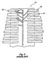
- FIG. 3shows a plurality of lead fingers 12 that is aligned on the perimeter of a particular semiconductor die 10 .
- the lead fingers 12are connected to a portion of the plurality of bond pads 14 , where multiple pads are bonded to particular lead fingers 12 .
- FIG. 2where a design would require multiple connections between V CC and V SS to be bonded multiple times, a limited number of pins are available.
- a semiconductor deviceincludes a die having an active surface bearing integrated circuitry, the die including a plurality of bond pads thereon connected to the integrated circuitry. At least one electrically conductive wire bond is made between first and second bond pads of the plurality of bond pads for providing external electrical connection between the two bond pads, which are not interconnected via the integrated circuitry within the die.
- the first bond padcan be a lead finger on the active surface and the second bond pad can be an option bond pad electrically connected to a third bond pad selected from the plurality of bond pads on the active surface via the integrated circuitry. Further, the third bond pad can connect to a fourth bond pad selected from the plurality of bond pads via a wire bond.
- the first bond padcan also be an internal voltage line and the second bond pad is an external voltage line or the bond pads can be different internal buses within the integrated circuitry.
- the semiconductor devicecan be fabricated in any type of processing or memory device desired.
- the bonding structurecan be utilized in a computer system having an input and output device, as well as a central processing unit.
- a methodis also disclosed that selects the appropriate bond pads and then provides the external electrical connection.
- FIG. 1is a prior art diagram of a voltage regulator having an external and internal connection
- FIG. 2is a prior art diagram of a process for shorting the external and internal connections of the regulator according to FIG. 1 ;
- FIG. 3is a prior art diagram of a plurality of bond pads used to connect to a given number of lead fingers of a lead frame having assembly limitation;
- FIG. 4Aillustrates in a top view the additional option pads according to the present invention
- FIG. 4Billustrates in a side view the additional option pads according to the present invention
- FIG. 5depicts a wiring scheme using the bond pads of FIGS. 4A and 4B ;
- FIGS. 6A and 6Billustrate an alternative wiring scheme of the bond pads according to the present invention
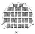
- FIG. 7is a top view of a semiconductor wafer comprising a plurality of the semiconductor device illustrated in FIGS. 4A and 4B ;
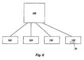
- FIG. 8is a block diagram of an electronic system incorporating the semiconductor device of FIGS. 4 A and 4 B.
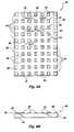
- FIGS. 4A and 4BA semiconductor device 20 is illustrated in FIGS. 4A and 4B .
- Semiconductor device 20includes a semiconductor die 22 of generally rectangular configuration.
- the semiconductor die 22has an active surface 24 carrying a plurality of bond pads 26 proximate its perimeter 28 and a plurality of functional option pads 30 , distinguished by surface shading in the drawing and disposed between the rows of peripheral bond pads 26 .
- the bond pads 26are formed as an integral part of die 22 , making contact with and providing an external contact for internal circuitry (not shown) contained within the semiconductor die 22 , as is known in the art.
- option pads 30are manufactured during the same processing step as that for the bond pads and are added to provide for selected functionality based upon the wiring step to be performed later. For example, as was shown in prior art FIG. 1 , it is necessary at times to tie the V CCX power source with the internally regulated V CCR power line. Thus, in FIG. 4A , extra V CC pads 30 are provided that allow additional connection between the external V CCX and the internal V CCR contacts. Since option pads 30 are processed at the same time that peripheral bond pads 26 are added and processed, the subsequent masking step required in FIG. 1 , or the fuse implementation, is eliminated, thus saving time and materials during processing.
- FIG. 5illustrates how the wire bonds are formed between pads that are to be interconnected.
- wire bonds 32 , 34 , and 36are connected between the various bond pads.
- wire bond 32connects V CCX pad 30 with V CCR pad 30 .
- Wire bond 34connects V CCX pad 30 to V CC pad 26 .
- Wire bond 36connects another pad 26 to a different option pad 30 .
- Other bonding schemesare possible according to the needs of the user.
- the termination points of wire bonds 32 , 34 , and 36can be a ball, wedge or other configuration as is known in the art and formed with a conventional wire bonding machine.
- the wire bondsare typically formed of small diameter wire material, such as, for example, small diameter wire of gold, aluminum, silver or other known materials and alloys thereof used in the art.
- FIG. 6Adepicts how multiple options pads 30 can be interconnected in such a fashion that a single wire bond or reduced number of wire bonds are made to outlying lead fingers 40 of a lead frame, which overcomes the interconnection problems described in the prior art with respect to FIG. 2 .
- Thisis useful when there is an assembly limitation on the number of wire bonds that can be made to a single lead finger of a lead frame for a particular semiconductor die and lead frame design. Again, this is seen in designs that require the V CC and the V SS to be bonded multiple times, but the scope of the invention is not limited to those particular pins.
- the present inventionmay be used with any other bond pads of semiconductor dice that require multiple lead connections.
- the V CC connection with lead finger 40is made to several different option pads 30 ; for example, different option pads 30 may be V CCR and V CCX thus relaxing the assembly requirements. Additionally, an advantage in using multiple option pads 30 is that if during the wire bonding process any shorts occur accidentally, such as shorts between wire bond 34 and wire bond 32 , there is no harm as the wires being shorted together have the same potential.
- the use of the multiple bond padsreduces the cost of manufacturing in that an additional metal mask step has been eliminated. This occurs by providing the same function by merely shorting across the pass device. Additionally, throughput is increased during the fabrication operation. Specifically, this occurs because of limiting the run to only one metal mask during fabrication for such operations as when differing voltage potentials are designed. For example, if a 3.3 volt (V) design is preferred over a 5 V design, the actual implementation on the same die can be made during the bonding process rather than adding a separate metal mask and step to provide the desired functionality.
- V3.3 volt
- the additional bond pads with wire interconnectionovercome the limitation of the number of bonds by interconnecting the bond pads before making one or a small number of actual bonds to a given lead finger.
- semiconductor devicesmay comprise an integrated circuit die employed for storing or processing digital information, including, for example, a Dynamic Random Access Memory (DRAM) integrated circuit die, a Static Random Access Memory (SRAM) integrated circuit die, a Synchronous Graphics Random Access Memory (SGRAM) integrated circuit die, a Programmable Read-Only Memory (PROM) integrated circuit die, an Electrically Erasable PROM (EEPROM) integrated circuit die, a flash memory die and a microprocessor die, and that the present invention includes such devices within its scope.
- DRAMDynamic Random Access Memory
- SRAMStatic Random Access Memory
- SGRAMSynchronous Graphics Random Access Memory
- PROMProgrammable Read-Only Memory
- EEPROMElectrically Erasable PROM
- the jumper padsmay be round, oblong, hemispherical or variously shaped and sized so long as the jumper pads provide enough surface area to accept attachment of one or more wire bonds thereto.
- the bond padsmay be positioned at any location on the active surface of the die.
- a semiconductor wafer 620incorporates a plurality of integrated circuit devices 20 (shown in increased scale and reduced numbers relative to the wafer 620 ) of FIGS. 4A and 4B .
- an electronic system 130includes an input device 132 and an output device 134 coupled to a processor device 136 which, in turn, is coupled to a memory device 138 incorporating the exemplary integrated circuit devices 20 of FIGS. 4A and 4B .
Landscapes
- Engineering & Computer Science (AREA)
- Computer Hardware Design (AREA)
- Microelectronics & Electronic Packaging (AREA)
- Power Engineering (AREA)
- Physics & Mathematics (AREA)
- Condensed Matter Physics & Semiconductors (AREA)
- General Physics & Mathematics (AREA)
- Semiconductor Integrated Circuits (AREA)
- Wire Bonding (AREA)
Abstract
Description
Claims (4)
Priority Applications (1)
| Application Number | Priority Date | Filing Date | Title |
|---|---|---|---|
| US10/633,923US6858472B2 (en) | 1998-01-22 | 2003-08-04 | Method for implementing selected functionality on an integrated circuit device |
Applications Claiming Priority (4)
| Application Number | Priority Date | Filing Date | Title |
|---|---|---|---|
| US09/012,113US6351040B1 (en) | 1998-01-22 | 1998-01-22 | Method and apparatus for implementing selected functionality on an integrated circuit device |
| US09/441,238US6348400B1 (en) | 1998-01-22 | 1999-11-16 | Method and apparatus for implementing selected functionality on an integrated circuit device |
| US09/944,505US6635560B2 (en) | 1998-01-22 | 2001-08-30 | Method for implementing selected functionality on an integrated circuit device |
| US10/633,923US6858472B2 (en) | 1998-01-22 | 2003-08-04 | Method for implementing selected functionality on an integrated circuit device |
Related Parent Applications (1)
| Application Number | Title | Priority Date | Filing Date |
|---|---|---|---|
| US09/944,505ContinuationUS6635560B2 (en) | 1998-01-22 | 2001-08-30 | Method for implementing selected functionality on an integrated circuit device |
Publications (2)
| Publication Number | Publication Date |
|---|---|
| US20040038512A1 US20040038512A1 (en) | 2004-02-26 |
| US6858472B2true US6858472B2 (en) | 2005-02-22 |
Family
ID=21753452
Family Applications (8)
| Application Number | Title | Priority Date | Filing Date |
|---|---|---|---|
| US09/012,113Expired - Fee RelatedUS6351040B1 (en) | 1998-01-22 | 1998-01-22 | Method and apparatus for implementing selected functionality on an integrated circuit device |
| US09/441,238Expired - Fee RelatedUS6348400B1 (en) | 1998-01-22 | 1999-11-16 | Method and apparatus for implementing selected functionality on an integrated circuit device |
| US09/846,005Expired - LifetimeUS6617692B2 (en) | 1998-01-22 | 2001-04-30 | Apparatus for implementing selected functionality on an integrated circuit device |
| US09/941,203Expired - LifetimeUS6472764B2 (en) | 1998-01-22 | 2001-08-28 | Method and apparatus for implementing selected functionality on an integrated circuit device |
| US09/944,505Expired - LifetimeUS6635560B2 (en) | 1998-01-22 | 2001-08-30 | Method for implementing selected functionality on an integrated circuit device |
| US10/157,479Expired - LifetimeUS6674177B2 (en) | 1998-01-22 | 2002-05-29 | Apparatus for implementing selected functionality on an integrated circuit device |
| US10/633,923Expired - Fee RelatedUS6858472B2 (en) | 1998-01-22 | 2003-08-04 | Method for implementing selected functionality on an integrated circuit device |
| US10/633,924Expired - LifetimeUS6897569B2 (en) | 1998-01-22 | 2003-08-04 | Apparatus for implementing selected functionality on an integrated circuit device in an electronic device |
Family Applications Before (6)
| Application Number | Title | Priority Date | Filing Date |
|---|---|---|---|
| US09/012,113Expired - Fee RelatedUS6351040B1 (en) | 1998-01-22 | 1998-01-22 | Method and apparatus for implementing selected functionality on an integrated circuit device |
| US09/441,238Expired - Fee RelatedUS6348400B1 (en) | 1998-01-22 | 1999-11-16 | Method and apparatus for implementing selected functionality on an integrated circuit device |
| US09/846,005Expired - LifetimeUS6617692B2 (en) | 1998-01-22 | 2001-04-30 | Apparatus for implementing selected functionality on an integrated circuit device |
| US09/941,203Expired - LifetimeUS6472764B2 (en) | 1998-01-22 | 2001-08-28 | Method and apparatus for implementing selected functionality on an integrated circuit device |
| US09/944,505Expired - LifetimeUS6635560B2 (en) | 1998-01-22 | 2001-08-30 | Method for implementing selected functionality on an integrated circuit device |
| US10/157,479Expired - LifetimeUS6674177B2 (en) | 1998-01-22 | 2002-05-29 | Apparatus for implementing selected functionality on an integrated circuit device |
Family Applications After (1)
| Application Number | Title | Priority Date | Filing Date |
|---|---|---|---|
| US10/633,924Expired - LifetimeUS6897569B2 (en) | 1998-01-22 | 2003-08-04 | Apparatus for implementing selected functionality on an integrated circuit device in an electronic device |
Country Status (1)
| Country | Link |
|---|---|
| US (8) | US6351040B1 (en) |
Cited By (13)
| Publication number | Priority date | Publication date | Assignee | Title |
|---|---|---|---|---|
| US20050156171A1 (en)* | 2003-12-30 | 2005-07-21 | Brask Justin K. | Nonplanar transistors with metal gate electrodes |
| US20060012390A1 (en)* | 2004-07-13 | 2006-01-19 | Inventec Corporation | Burn-in adapter |
| US20060157687A1 (en)* | 2005-01-18 | 2006-07-20 | Doyle Brian S | Non-planar MOS structure with a strained channel region |
| US20060172497A1 (en)* | 2003-06-27 | 2006-08-03 | Hareland Scott A | Nonplanar semiconductor device with partially or fully wrapped around gate electrode and methods of fabrication |
| US20070040223A1 (en)* | 2005-08-17 | 2007-02-22 | Intel Corporation | Lateral undercut of metal gate in SOI device |
| US20090149012A1 (en)* | 2004-09-30 | 2009-06-11 | Brask Justin K | Method of forming a nonplanar transistor with sidewall spacers |
| US20100297838A1 (en)* | 2004-09-29 | 2010-11-25 | Chang Peter L D | Independently accessed double-gate and tri-gate transistors in same process flow |
| US20110062512A1 (en)* | 2004-10-25 | 2011-03-17 | Uday Shah | Nonplanar device with thinned lower body portion and method of fabrication |
| US7960794B2 (en) | 2004-08-10 | 2011-06-14 | Intel Corporation | Non-planar pMOS structure with a strained channel region and an integrated strained CMOS flow |
| US8084818B2 (en) | 2004-06-30 | 2011-12-27 | Intel Corporation | High mobility tri-gate devices and methods of fabrication |
| US8183646B2 (en) | 2005-02-23 | 2012-05-22 | Intel Corporation | Field effect transistor with narrow bandgap source and drain regions and method of fabrication |
| US8362566B2 (en) | 2008-06-23 | 2013-01-29 | Intel Corporation | Stress in trigate devices using complimentary gate fill materials |
| US8405164B2 (en) | 2003-06-27 | 2013-03-26 | Intel Corporation | Tri-gate transistor device with stress incorporation layer and method of fabrication |
Families Citing this family (24)
| Publication number | Priority date | Publication date | Assignee | Title |
|---|---|---|---|---|
| US6351040B1 (en)* | 1998-01-22 | 2002-02-26 | Micron Technology, Inc. | Method and apparatus for implementing selected functionality on an integrated circuit device |
| KR100426989B1 (en)* | 2001-06-13 | 2004-04-13 | 삼성전자주식회사 | Control signal providing method using package power pins and IC package structure therefore |
| US8258616B1 (en) | 2002-01-16 | 2012-09-04 | Marvell International Ltd. | Semiconductor dice having a shielded area created under bond wires connecting pairs of bonding pads |
| US6770982B1 (en)* | 2002-01-16 | 2004-08-03 | Marvell International, Ltd. | Semiconductor device power distribution system and method |
| US6753482B1 (en)* | 2002-05-06 | 2004-06-22 | Micron Technology, Inc. | Semiconductor component with adjustment circuitry |
| US7326594B2 (en)* | 2002-07-31 | 2008-02-05 | Microchip Technology Incorporated | Connecting a plurality of bond pads and/or inner leads with a single bond wire |
| US7157790B2 (en)* | 2002-07-31 | 2007-01-02 | Microchip Technology Inc. | Single die stitch bonding |
| JP3880572B2 (en)* | 2003-10-31 | 2007-02-14 | 沖電気工業株式会社 | Semiconductor chip and semiconductor device |
| US6965170B2 (en)* | 2003-11-18 | 2005-11-15 | International Business Machines Corporation | High wireability microvia substrate |
| JP3881658B2 (en)* | 2004-01-23 | 2007-02-14 | 沖電気工業株式会社 | Relay member, multi-chip package using relay member, and manufacturing method thereof |
| US7173328B2 (en)* | 2004-04-06 | 2007-02-06 | Lsi Logic Corporation | Integrated circuit package and method having wire-bonded intra-die electrical connections |
| TWI242873B (en)* | 2004-04-23 | 2005-11-01 | Chiplus Semiconductor Corp | Integrated circuit packaging method and structure for redistributing configuration thereof |
| US20050245062A1 (en)* | 2004-04-29 | 2005-11-03 | Jeff Kingsbury | Single row bond pad arrangement |
| US7737553B2 (en)* | 2004-10-06 | 2010-06-15 | Panasonic Corporation | Semiconductor device |
| US8063746B2 (en)* | 2006-03-31 | 2011-11-22 | Assa Abloy Ab | Transponder detector for an RFID system generating a progression of detection signals |
| US7629675B2 (en)* | 2006-05-03 | 2009-12-08 | Marvell International Technology Ltd. | System and method for routing signals between side-by-side die in lead frame type system in a package (SIP) devices |
| US8922028B2 (en)* | 2007-02-13 | 2014-12-30 | Advanced Semiconductor Engineering, Inc. | Semiconductor package |
| US7663204B2 (en)* | 2007-04-27 | 2010-02-16 | Powertech Technology Inc. | Substrate for multi-chip stacking, multi-chip stack package utilizing the substrate and its applications |
| US7696631B2 (en)* | 2007-12-10 | 2010-04-13 | International Business Machines Corporation | Wire bonding personalization and discrete component attachment on wirebond pads |
| US20100171211A1 (en)* | 2009-01-07 | 2010-07-08 | Che-Yuan Jao | Semiconductor device |
| US20150206855A1 (en)* | 2014-01-22 | 2015-07-23 | Mediatek Inc. | Semiconductor package |
| US9236363B2 (en)* | 2014-03-11 | 2016-01-12 | Freescale Semiconductor, Inc. | Wedge bond foot jumper connections |
| TWI538257B (en)* | 2014-06-25 | 2016-06-11 | 群聯電子股份有限公司 | System in package structure, electroplating module thereof and memory storage device |
| CN112652598A (en)* | 2019-10-10 | 2021-04-13 | 长鑫存储技术有限公司 | Pad and dynamic random access memory |
Citations (22)
| Publication number | Priority date | Publication date | Assignee | Title |
|---|---|---|---|---|
| US4213141A (en) | 1978-05-12 | 1980-07-15 | Solid State Scientific Inc. | Hybrid transistor |
| US4403240A (en) | 1979-10-26 | 1983-09-06 | Hitachi, Ltd. | Integrated circuit with at least three ground pads |
| US5043943A (en) | 1990-06-18 | 1991-08-27 | Motorola, Inc. | Cache memory with a parity write control circuit |
| US5170312A (en) | 1991-11-04 | 1992-12-08 | Motorola, Inc. | Protection circuit on a lead of a power device |
| US5303180A (en) | 1991-08-29 | 1994-04-12 | Texas Instruments Incorporated | Pin programmable dram that allows customer to program option desired |
| US5353250A (en) | 1991-12-09 | 1994-10-04 | Texas Instruments Inc. | Pin programmable dram that provides customer option programmability |
| US5354955A (en) | 1992-12-02 | 1994-10-11 | International Business Machines Corporation | Direct jump engineering change system |
| US5399904A (en) | 1992-11-05 | 1995-03-21 | Kabushiki Kaisha Toshiba | Array type semiconductor device having insulating circuit board |
| US5455460A (en) | 1991-04-05 | 1995-10-03 | Mitsubishi Denki Kabushiki Kaisha | Semiconductor device having complimentary bonding pads |
| US5473196A (en) | 1993-02-02 | 1995-12-05 | Matra Marconi Space France | Semiconductor memory component comprising stacked memory modules |
| US5598967A (en) | 1995-04-04 | 1997-02-04 | Motorola, Inc. | Method and structure for attaching a circuit module to a circuit board |
| US5612575A (en) | 1994-05-20 | 1997-03-18 | Matra Marconi Space France | Method of connecting the output pads on an integrated circuit chip, and multichip module thus obtained |
| US5682105A (en) | 1994-11-29 | 1997-10-28 | Nec Corporation | Bonding option circuit having no pass-through current |
| US5763298A (en) | 1995-05-09 | 1998-06-09 | United Memories, Inc. | Bond pad option for integrated circuits |
| US5838072A (en) | 1997-02-24 | 1998-11-17 | Mosel Vitalic Corporation | Intrachip power distribution package and method for semiconductors having a supply node electrically interconnected with one or more intermediate nodes |
| US5880596A (en) | 1996-11-05 | 1999-03-09 | Altera Corporation | Apparatus and method for configuring integrated circuit option bits with different bonding patterns |
| US5989939A (en) | 1996-12-13 | 1999-11-23 | Tessera, Inc. | Process of manufacturing compliant wirebond packages |
| US6097098A (en)* | 1997-02-14 | 2000-08-01 | Micron Technology, Inc. | Die interconnections using intermediate connection elements secured to the die face |
| US6169329B1 (en)* | 1996-04-02 | 2001-01-02 | Micron Technology, Inc. | Semiconductor devices having interconnections using standardized bonding locations and methods of designing |
| US6194774B1 (en) | 1999-03-10 | 2001-02-27 | Samsung Electronics Co., Ltd. | Inductor including bonding wires |
| US6348400B1 (en) | 1998-01-22 | 2002-02-19 | Micron Technology, Inc. | Method and apparatus for implementing selected functionality on an integrated circuit device |
| US6462404B1 (en)* | 1997-02-28 | 2002-10-08 | Micron Technology, Inc. | Multilevel leadframe for a packaged integrated circuit |
- 1998
- 1998-01-22USUS09/012,113patent/US6351040B1/ennot_activeExpired - Fee Related
- 1999
- 1999-11-16USUS09/441,238patent/US6348400B1/ennot_activeExpired - Fee Related
- 2001
- 2001-04-30USUS09/846,005patent/US6617692B2/ennot_activeExpired - Lifetime
- 2001-08-28USUS09/941,203patent/US6472764B2/ennot_activeExpired - Lifetime
- 2001-08-30USUS09/944,505patent/US6635560B2/ennot_activeExpired - Lifetime
- 2002
- 2002-05-29USUS10/157,479patent/US6674177B2/ennot_activeExpired - Lifetime
- 2003
- 2003-08-04USUS10/633,923patent/US6858472B2/ennot_activeExpired - Fee Related
- 2003-08-04USUS10/633,924patent/US6897569B2/ennot_activeExpired - Lifetime
Patent Citations (24)
| Publication number | Priority date | Publication date | Assignee | Title |
|---|---|---|---|---|
| US4213141A (en) | 1978-05-12 | 1980-07-15 | Solid State Scientific Inc. | Hybrid transistor |
| US4403240A (en) | 1979-10-26 | 1983-09-06 | Hitachi, Ltd. | Integrated circuit with at least three ground pads |
| US5043943A (en) | 1990-06-18 | 1991-08-27 | Motorola, Inc. | Cache memory with a parity write control circuit |
| US5455460A (en) | 1991-04-05 | 1995-10-03 | Mitsubishi Denki Kabushiki Kaisha | Semiconductor device having complimentary bonding pads |
| US5303180A (en) | 1991-08-29 | 1994-04-12 | Texas Instruments Incorporated | Pin programmable dram that allows customer to program option desired |
| US5170312A (en) | 1991-11-04 | 1992-12-08 | Motorola, Inc. | Protection circuit on a lead of a power device |
| US5353250A (en) | 1991-12-09 | 1994-10-04 | Texas Instruments Inc. | Pin programmable dram that provides customer option programmability |
| US5399904A (en) | 1992-11-05 | 1995-03-21 | Kabushiki Kaisha Toshiba | Array type semiconductor device having insulating circuit board |
| US5354955A (en) | 1992-12-02 | 1994-10-11 | International Business Machines Corporation | Direct jump engineering change system |
| US5473196A (en) | 1993-02-02 | 1995-12-05 | Matra Marconi Space France | Semiconductor memory component comprising stacked memory modules |
| US5612575A (en) | 1994-05-20 | 1997-03-18 | Matra Marconi Space France | Method of connecting the output pads on an integrated circuit chip, and multichip module thus obtained |
| US5682105A (en) | 1994-11-29 | 1997-10-28 | Nec Corporation | Bonding option circuit having no pass-through current |
| US5598967A (en) | 1995-04-04 | 1997-02-04 | Motorola, Inc. | Method and structure for attaching a circuit module to a circuit board |
| US5763298A (en) | 1995-05-09 | 1998-06-09 | United Memories, Inc. | Bond pad option for integrated circuits |
| US6169329B1 (en)* | 1996-04-02 | 2001-01-02 | Micron Technology, Inc. | Semiconductor devices having interconnections using standardized bonding locations and methods of designing |
| US5880596A (en) | 1996-11-05 | 1999-03-09 | Altera Corporation | Apparatus and method for configuring integrated circuit option bits with different bonding patterns |
| US5989939A (en) | 1996-12-13 | 1999-11-23 | Tessera, Inc. | Process of manufacturing compliant wirebond packages |
| US6097098A (en)* | 1997-02-14 | 2000-08-01 | Micron Technology, Inc. | Die interconnections using intermediate connection elements secured to the die face |
| US5838072A (en) | 1997-02-24 | 1998-11-17 | Mosel Vitalic Corporation | Intrachip power distribution package and method for semiconductors having a supply node electrically interconnected with one or more intermediate nodes |
| US6462404B1 (en)* | 1997-02-28 | 2002-10-08 | Micron Technology, Inc. | Multilevel leadframe for a packaged integrated circuit |
| US6348400B1 (en) | 1998-01-22 | 2002-02-19 | Micron Technology, Inc. | Method and apparatus for implementing selected functionality on an integrated circuit device |
| US6351040B1 (en) | 1998-01-22 | 2002-02-26 | Micron Technology, Inc. | Method and apparatus for implementing selected functionality on an integrated circuit device |
| US6472764B2 (en) | 1998-01-22 | 2002-10-29 | Micron Technology, Inc. | Method and apparatus for implementing selected functionality on an integrated circuit device |
| US6194774B1 (en) | 1999-03-10 | 2001-02-27 | Samsung Electronics Co., Ltd. | Inductor including bonding wires |
Non-Patent Citations (1)
| Title |
|---|
| IBM Technical Disclosure, "Replaceable Engineering Change Pad," Jan. 1973, pp. 2575-2576. |
Cited By (39)
| Publication number | Priority date | Publication date | Assignee | Title |
|---|---|---|---|---|
| US8405164B2 (en) | 2003-06-27 | 2013-03-26 | Intel Corporation | Tri-gate transistor device with stress incorporation layer and method of fabrication |
| US20060172497A1 (en)* | 2003-06-27 | 2006-08-03 | Hareland Scott A | Nonplanar semiconductor device with partially or fully wrapped around gate electrode and methods of fabrication |
| US7329913B2 (en) | 2003-12-30 | 2008-02-12 | Intel Corporation | Nonplanar transistors with metal gate electrodes |
| US20050156171A1 (en)* | 2003-12-30 | 2005-07-21 | Brask Justin K. | Nonplanar transistors with metal gate electrodes |
| US8084818B2 (en) | 2004-06-30 | 2011-12-27 | Intel Corporation | High mobility tri-gate devices and methods of fabrication |
| US20060012390A1 (en)* | 2004-07-13 | 2006-01-19 | Inventec Corporation | Burn-in adapter |
| US7005877B2 (en)* | 2004-07-13 | 2006-02-28 | Inventec Corporation | Burn-in adapter |
| US7960794B2 (en) | 2004-08-10 | 2011-06-14 | Intel Corporation | Non-planar pMOS structure with a strained channel region and an integrated strained CMOS flow |
| US20100297838A1 (en)* | 2004-09-29 | 2010-11-25 | Chang Peter L D | Independently accessed double-gate and tri-gate transistors in same process flow |
| US8399922B2 (en) | 2004-09-29 | 2013-03-19 | Intel Corporation | Independently accessed double-gate and tri-gate transistors |
| US8268709B2 (en) | 2004-09-29 | 2012-09-18 | Intel Corporation | Independently accessed double-gate and tri-gate transistors in same process flow |
| US20090149012A1 (en)* | 2004-09-30 | 2009-06-11 | Brask Justin K | Method of forming a nonplanar transistor with sidewall spacers |
| US10236356B2 (en) | 2004-10-25 | 2019-03-19 | Intel Corporation | Nonplanar device with thinned lower body portion and method of fabrication |
| US20110062512A1 (en)* | 2004-10-25 | 2011-03-17 | Uday Shah | Nonplanar device with thinned lower body portion and method of fabrication |
| US9190518B2 (en) | 2004-10-25 | 2015-11-17 | Intel Corporation | Nonplanar device with thinned lower body portion and method of fabrication |
| US8067818B2 (en) | 2004-10-25 | 2011-11-29 | Intel Corporation | Nonplanar device with thinned lower body portion and method of fabrication |
| US9741809B2 (en) | 2004-10-25 | 2017-08-22 | Intel Corporation | Nonplanar device with thinned lower body portion and method of fabrication |
| US8749026B2 (en) | 2004-10-25 | 2014-06-10 | Intel Corporation | Nonplanar device with thinned lower body portion and method of fabrication |
| US8502351B2 (en) | 2004-10-25 | 2013-08-06 | Intel Corporation | Nonplanar device with thinned lower body portion and method of fabrication |
| US7193279B2 (en) | 2005-01-18 | 2007-03-20 | Intel Corporation | Non-planar MOS structure with a strained channel region |
| US20060157687A1 (en)* | 2005-01-18 | 2006-07-20 | Doyle Brian S | Non-planar MOS structure with a strained channel region |
| US8816394B2 (en) | 2005-02-23 | 2014-08-26 | Intel Corporation | Field effect transistor with narrow bandgap source and drain regions and method of fabrication |
| US9368583B2 (en) | 2005-02-23 | 2016-06-14 | Intel Corporation | Field effect transistor with narrow bandgap source and drain regions and method of fabrication |
| US10121897B2 (en) | 2005-02-23 | 2018-11-06 | Intel Corporation | Field effect transistor with narrow bandgap source and drain regions and method of fabrication |
| US8664694B2 (en) | 2005-02-23 | 2014-03-04 | Intel Corporation | Field effect transistor with narrow bandgap source and drain regions and method of fabrication |
| US9748391B2 (en) | 2005-02-23 | 2017-08-29 | Intel Corporation | Field effect transistor with narrow bandgap source and drain regions and method of fabrication |
| US8183646B2 (en) | 2005-02-23 | 2012-05-22 | Intel Corporation | Field effect transistor with narrow bandgap source and drain regions and method of fabrication |
| US8368135B2 (en) | 2005-02-23 | 2013-02-05 | Intel Corporation | Field effect transistor with narrow bandgap source and drain regions and method of fabrication |
| US9048314B2 (en) | 2005-02-23 | 2015-06-02 | Intel Corporation | Field effect transistor with narrow bandgap source and drain regions and method of fabrication |
| US9614083B2 (en) | 2005-02-23 | 2017-04-04 | Intel Corporation | Field effect transistor with narrow bandgap source and drain regions and method of fabrication |
| US7402875B2 (en) | 2005-08-17 | 2008-07-22 | Intel Corporation | Lateral undercut of metal gate in SOI device |
| US20080188041A1 (en)* | 2005-08-17 | 2008-08-07 | Suman Datta | Lateral undercut of metal gate in SOI device |
| US7736956B2 (en) | 2005-08-17 | 2010-06-15 | Intel Corporation | Lateral undercut of metal gate in SOI device |
| US20070040223A1 (en)* | 2005-08-17 | 2007-02-22 | Intel Corporation | Lateral undercut of metal gate in SOI device |
| US9224754B2 (en) | 2008-06-23 | 2015-12-29 | Intel Corporation | Stress in trigate devices using complimentary gate fill materials |
| US9450092B2 (en) | 2008-06-23 | 2016-09-20 | Intel Corporation | Stress in trigate devices using complimentary gate fill materials |
| US8741733B2 (en) | 2008-06-23 | 2014-06-03 | Intel Corporation | Stress in trigate devices using complimentary gate fill materials |
| US9806193B2 (en) | 2008-06-23 | 2017-10-31 | Intel Corporation | Stress in trigate devices using complimentary gate fill materials |
| US8362566B2 (en) | 2008-06-23 | 2013-01-29 | Intel Corporation | Stress in trigate devices using complimentary gate fill materials |
Also Published As
| Publication number | Publication date |
|---|---|
| US20040026772A1 (en) | 2004-02-12 |
| US6635560B2 (en) | 2003-10-21 |
| US6348400B1 (en) | 2002-02-19 |
| US6674177B2 (en) | 2004-01-06 |
| US6351040B1 (en) | 2002-02-26 |
| US20020140111A1 (en) | 2002-10-03 |
| US6472764B2 (en) | 2002-10-29 |
| US6617692B2 (en) | 2003-09-09 |
| US20010026022A1 (en) | 2001-10-04 |
| US20040038512A1 (en) | 2004-02-26 |
| US20020024128A1 (en) | 2002-02-28 |
| US20020031873A1 (en) | 2002-03-14 |
| US6897569B2 (en) | 2005-05-24 |
Similar Documents
| Publication | Publication Date | Title |
|---|---|---|
| US6858472B2 (en) | Method for implementing selected functionality on an integrated circuit device | |
| US6831353B2 (en) | Interdigitated leads-over-chip lead frame and device for supporting an integrated circuit die | |
| US6777801B2 (en) | Semiconductor device and method of manufacturing same | |
| US6956294B2 (en) | Apparatus for routing die interconnections using intermediate connection elements secured to the die face | |
| US7482699B2 (en) | Semiconductor device | |
| US5789816A (en) | Multiple-chip integrated circuit package including a dummy chip | |
| US7808092B2 (en) | Semiconductor device with a plurality of ground planes | |
| KR970006529B1 (en) | Semiconductor device | |
| US6590297B2 (en) | Semiconductor chip having pads with plural junctions for different assembly methods | |
| US7199460B2 (en) | Semiconductor device and method of manufacturing the same | |
| KR950014121B1 (en) | Semiconductor devices | |
| JP4056252B2 (en) | Manufacturing method of semiconductor device | |
| JP2972473B2 (en) | Semiconductor device | |
| JPH0673365B2 (en) | Semiconductor device | |
| JPH07297352A (en) | Semiconductor device | |
| JPS59124151A (en) | Semiconductor integrated circuit device |
Legal Events
| Date | Code | Title | Description |
|---|---|---|---|
| FEPP | Fee payment procedure | Free format text:PAYOR NUMBER ASSIGNED (ORIGINAL EVENT CODE: ASPN); ENTITY STATUS OF PATENT OWNER: LARGE ENTITY | |
| FPAY | Fee payment | Year of fee payment:4 | |
| FPAY | Fee payment | Year of fee payment:8 | |
| AS | Assignment | Owner name:U.S. BANK NATIONAL ASSOCIATION, AS COLLATERAL AGENT, CALIFORNIA Free format text:SECURITY INTEREST;ASSIGNOR:MICRON TECHNOLOGY, INC.;REEL/FRAME:038669/0001 Effective date:20160426 Owner name:U.S. BANK NATIONAL ASSOCIATION, AS COLLATERAL AGEN Free format text:SECURITY INTEREST;ASSIGNOR:MICRON TECHNOLOGY, INC.;REEL/FRAME:038669/0001 Effective date:20160426 | |
| AS | Assignment | Owner name:MORGAN STANLEY SENIOR FUNDING, INC., AS COLLATERAL AGENT, MARYLAND Free format text:PATENT SECURITY AGREEMENT;ASSIGNOR:MICRON TECHNOLOGY, INC.;REEL/FRAME:038954/0001 Effective date:20160426 Owner name:MORGAN STANLEY SENIOR FUNDING, INC., AS COLLATERAL Free format text:PATENT SECURITY AGREEMENT;ASSIGNOR:MICRON TECHNOLOGY, INC.;REEL/FRAME:038954/0001 Effective date:20160426 | |
| REMI | Maintenance fee reminder mailed | ||
| LAPS | Lapse for failure to pay maintenance fees | ||
| STCH | Information on status: patent discontinuation | Free format text:PATENT EXPIRED DUE TO NONPAYMENT OF MAINTENANCE FEES UNDER 37 CFR 1.362 | |
| FP | Lapsed due to failure to pay maintenance fee | Effective date:20170222 | |
| AS | Assignment | Owner name:U.S. BANK NATIONAL ASSOCIATION, AS COLLATERAL AGENT, CALIFORNIA Free format text:CORRECTIVE ASSIGNMENT TO CORRECT THE REPLACE ERRONEOUSLY FILED PATENT #7358718 WITH THE CORRECT PATENT #7358178 PREVIOUSLY RECORDED ON REEL 038669 FRAME 0001. ASSIGNOR(S) HEREBY CONFIRMS THE SECURITY INTEREST;ASSIGNOR:MICRON TECHNOLOGY, INC.;REEL/FRAME:043079/0001 Effective date:20160426 Owner name:U.S. BANK NATIONAL ASSOCIATION, AS COLLATERAL AGEN Free format text:CORRECTIVE ASSIGNMENT TO CORRECT THE REPLACE ERRONEOUSLY FILED PATENT #7358718 WITH THE CORRECT PATENT #7358178 PREVIOUSLY RECORDED ON REEL 038669 FRAME 0001. ASSIGNOR(S) HEREBY CONFIRMS THE SECURITY INTEREST;ASSIGNOR:MICRON TECHNOLOGY, INC.;REEL/FRAME:043079/0001 Effective date:20160426 | |
| AS | Assignment | Owner name:MICRON TECHNOLOGY, INC., IDAHO Free format text:RELEASE BY SECURED PARTY;ASSIGNOR:U.S. BANK NATIONAL ASSOCIATION, AS COLLATERAL AGENT;REEL/FRAME:047243/0001 Effective date:20180629 | |
| AS | Assignment | Owner name:MICRON TECHNOLOGY, INC., IDAHO Free format text:RELEASE BY SECURED PARTY;ASSIGNOR:MORGAN STANLEY SENIOR FUNDING, INC., AS COLLATERAL AGENT;REEL/FRAME:050937/0001 Effective date:20190731 |