US6857897B2 - Remote cable assist - Google Patents
Remote cable assistDownload PDFInfo
- Publication number
- US6857897B2 US6857897B2US10/425,409US42540903AUS6857897B2US 6857897 B2US6857897 B2US 6857897B2US 42540903 AUS42540903 AUS 42540903AUS 6857897 B2US6857897 B2US 6857897B2
- Authority
- US
- United States
- Prior art keywords
- cable
- connector
- locator
- computer
- processor
- Prior art date
- Legal status (The legal status is an assumption and is not a legal conclusion. Google has not performed a legal analysis and makes no representation as to the accuracy of the status listed.)
- Expired - Lifetime, expires
Links
Images


Classifications
- G—PHYSICS
- G06—COMPUTING OR CALCULATING; COUNTING
- G06F—ELECTRIC DIGITAL DATA PROCESSING
- G06F3/00—Input arrangements for transferring data to be processed into a form capable of being handled by the computer; Output arrangements for transferring data from processing unit to output unit, e.g. interface arrangements
- G06F3/01—Input arrangements or combined input and output arrangements for interaction between user and computer
- G06F3/03—Arrangements for converting the position or the displacement of a member into a coded form
- G06F3/033—Pointing devices displaced or positioned by the user, e.g. mice, trackballs, pens or joysticks; Accessories therefor
- G06F3/038—Control and interface arrangements therefor, e.g. drivers or device-embedded control circuitry
- G06F3/0383—Signal control means within the pointing device
- G—PHYSICS
- G06—COMPUTING OR CALCULATING; COUNTING
- G06F—ELECTRIC DIGITAL DATA PROCESSING
- G06F1/00—Details not covered by groups G06F3/00 - G06F13/00 and G06F21/00
- G06F1/16—Constructional details or arrangements
- G06F1/18—Packaging or power distribution
- G06F1/181—Enclosures
- G—PHYSICS
- G06—COMPUTING OR CALCULATING; COUNTING
- G06F—ELECTRIC DIGITAL DATA PROCESSING
- G06F3/00—Input arrangements for transferring data to be processed into a form capable of being handled by the computer; Output arrangements for transferring data from processing unit to output unit, e.g. interface arrangements
- G06F3/01—Input arrangements or combined input and output arrangements for interaction between user and computer
- G06F3/02—Input arrangements using manually operated switches, e.g. using keyboards or dials
- G06F3/023—Arrangements for converting discrete items of information into a coded form, e.g. arrangements for interpreting keyboard generated codes as alphanumeric codes, operand codes or instruction codes
- H—ELECTRICITY
- H01—ELECTRIC ELEMENTS
- H01R—ELECTRICALLY-CONDUCTIVE CONNECTIONS; STRUCTURAL ASSOCIATIONS OF A PLURALITY OF MUTUALLY-INSULATED ELECTRICAL CONNECTING ELEMENTS; COUPLING DEVICES; CURRENT COLLECTORS
- H01R13/00—Details of coupling devices of the kinds covered by groups H01R12/70 or H01R24/00 - H01R33/00
- H01R13/64—Means for preventing incorrect coupling
- H—ELECTRICITY
- H01—ELECTRIC ELEMENTS
- H01R—ELECTRICALLY-CONDUCTIVE CONNECTIONS; STRUCTURAL ASSOCIATIONS OF A PLURALITY OF MUTUALLY-INSULATED ELECTRICAL CONNECTING ELEMENTS; COUPLING DEVICES; CURRENT COLLECTORS
- H01R2201/00—Connectors or connections adapted for particular applications
- H01R2201/04—Connectors or connections adapted for particular applications for network, e.g. LAN connectors
Definitions
- Electronic devicessuch as computer components and peripherals, are often coupled together via a communication cable.
- a printermay be coupled to a laptop or desktop computer via a parallel cable.
- the location of the proper receptacle for the communication cablemay be uncertain or difficult to identify.
- a usermay have difficulty connecting the communication cable to the proper receptacle if it is located in a dark area, a tight space, or another area having limited accessibility or visibility.
- the foregoing connection difficultiesare generally worse in applications having multiple receptacles for communication cables.
- a computer systemmay have one or more parallel ports, serial ports, Universal Serial Bus (USB) ports, Institute of Electrical and Electronics Engineers (IEEE)—1394 ports, network ports, modem ports, and so forth. Accordingly, a user may be unable to locate the appropriate port for the desired communication cable.
- USBUniversal Serial Bus
- IEEEInstitute of Electrical and Electronics Engineers
- FIG. 1is a block diagram illustrating a locator-assisted connection system in accordance with certain embodiments of the present invention
- FIG. 2is a block diagram illustrating an alternative embodiment of the system having a plurality of peripherals coupled to a computer;
- FIG. 3is a side view illustrating a component having a wireless receiver, a location indicator, and a locator light disposed adjacent a connector in accordance with certain embodiments of the present invention
- FIG. 4is a block diagram illustrating an alternative embodiment of the locator-assisted connection system having a wireless transmitter and a trigger disposed within a peripheral;
- FIG. 5is a block diagram illustrating an alternative embodiment of the locator-assisted connection system having the wireless transmitter and the trigger disposed within a cable;
- FIG. 6is a side view illustrating an embodiment of the cable having the wireless transmitter and the trigger disposed within an end connector
- FIG. 7is a side view illustrating a connector module having the wireless transmitter and the trigger in accordance with certain embodiments of the present invention.
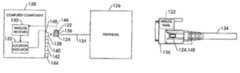
- FIG. 1is a block diagram of a system 10 in accordance with certain embodiments of the present invention.
- the system 10comprises devices 12 and 14 communicatively coupled together via a cable 16 .
- the devices 12 and 14may comprise a wide variety of electronics, computer components and peripherals, network devices, and so forth.
- the devices 12 and 14may comprise electronic devices disposed in separate locations, such as in a network.
- the system 10may comprise a computer system, a network, or any other connectable system of devices.
- the device 12comprises a wireless transmitter 18 , a trigger 20 , and a connector 22
- the device 14comprises a wireless receiver 24 , a location indicator 26 , and a connector 28
- the wireless transmitter 18 and the wireless receiver 24may comprise radio frequency (RF) circuitry, infrared or other optical communication circuitry, blue tooth technology, or other suitable wireless communication circuitry.
- the trigger 20may comprise a button, a switch, an event activated trigger, a voice activated trigger, a software activated trigger, a hardware activated trigger, or other suitable user interactive or automatic triggers.
- the location indicator 26may comprise a light such as a light emitting diode (LED), a vibration mechanism, an audio device, or other indicators that may be identified by one of the user's senses.
- the location indicator 26also may comprise a variety of different light colors (e.g., red, blue, green, etc.), vibrational signals, audio tones or signals, and so forth.
- the connectors 22 and 28may comprise parallel port connectors, serial port connectors, Universal Serial Bus (USB) connectors, Institute of Electrical and Electronics Engineers (IEEE)—1394 connectors, network connectors, modem connectors, and so forth. Accordingly, the cable 16 has end connectors configured to interface the particular interface format of the connectors 22 and 28 .
- the wireless transmitter 18 and the trigger 20may be disposed within the device 12 , within the cable 16 (e.g., in one of the end connectors), within a module connectable with both the cable and one of the connectors 22 and 28 , or in other configurations. It also should be noted that the device 14 may comprise one or more additional connectors, wherein the location indicator 26 is disposed adjacent a connector 28 .
- the location indicator 26identifies the location of the connector 28 for proper connection of the devices 12 and 14 via the cable 16 .
- the wireless transmitter 18transmits a control signal 30 to the wireless receiver 24 in response to engagement of the trigger 20 .
- a usermay engage the trigger 20 at the device 12 , at an end connector of the cable 16 , at a software interface, or at another location/interface.
- the control signal 30may comprise a variety of wireless signals or data, such as an on/off control, a device identifier, a connector identifier, a cable-type identifier, or other such data.
- the location indicator 26activates a signal 32 , such as a light or other user-identifiable signal. The user then locates the connector 28 corresponding to the signal 32 and communicatively couples the cable 16 with the connector 28 . Accordingly, the location indicator 26 assists a user in connecting the cable 16 to the correct connector 28 regardless of the user's knowledge of connector types, devices, or other system information.
- a signal 32such as a light or other user-identifiable signal.
- FIG. 2is a block diagram illustrating an alternative embodiment of the system 10 having a plurality of peripheral devices 34 , 36 , 38 , 40 , 42 , 44 , and 46 communicatively coupled to a computer 48 .
- the illustrated peripheral devices 34 , 36 , 38 , 40 , 42 , 44 , and 46comprise a display, a keyboard, a pointing device (e.g., a mouse, a touch pad, a joystick, a digitizer pad/pen, etc.), a printer, a scanner, a camera, and a peripheral, respectively.
- a pointing devicee.g., a mouse, a touch pad, a joystick, a digitizer pad/pen, etc.
- printere.g., a printer
- scannere.g., a scanner
- camerae.g., a camera
- peripherale.g., a printer
- other input, output, and user-interactive devicesmay be connected with the system 10 .
- the computer 48comprises a wireless receiver 50 , a controller or location indicator 52 communicative with the wireless receiver 50 , and a plurality of locator lights or light emitting diodes (LEDS) 54 , 56 , 58 , 60 , 62 , 64 , and 66 communicative with the location indicator 52 .
- Each of the locator lights 54 , 56 , 58 , 60 , 62 , 64 , and 66is disposed adjacent a particular communication connector, such as connectors 68 , 70 , 72 , 74 , 76 , 78 , and 79 , respectively.
- the system 10 of FIG. 2also comprises a wireless transmitter and trigger, similar to those described with reference to FIG.
- the wireless transmittercommunicates a control signal to the wireless receiver 50 , thereby activating the location indicator 52 to illuminate one of the locator lights 54 , 56 , 58 , 60 , 62 , 64 , and 66 associated with the correct one of the connectors 68 , 70 , 72 , 74 , 76 , 78 , and 79 , respectively.
- each one of the peripheral devices 34 , 36 , 38 , 40 , 42 , 44 , and 46may be communicatively coupled to the appropriate connectors 68 , 70 , 72 , 74 , 76 , 78 , and 79 via cables 80 , 82 , 84 , 86 , 88 , 90 , 92 , and 94 , respectively.
- the wireless transmitter and triggermaybe incorporated into the peripheral devices 34 , 36 , 38 , 40 , 42 , 44 , and 46 or the cables 80 , 82 , 84 , 86 , 88 , 90 , 92 , and 94 .
- the wireless transmitter and triggermay be incorporated into the cables 80 , 82 , 84 , 86 , 88 , 90 , and 92 at end plugs 94 , 96 , 98 , 100 , 102 , 104 , and 106 , respectively.
- FIG. 3is a side view of a component 110 having a wireless receiver 112 , a location indicator 114 , and a user identifiable locator or light 116 in accordance with another embodiment of the present invention.
- the user identifiable locator or light 116is disposed adjacent a connector 118 , which is communicatively coupled with circuitry (not shown) and a connector 120 on the component 110 .
- the component 110may comprise a variety of circuit boards or card-based computer components, such as a network card, a modem, a video card, an audio card, a security card, a network management card, a wireless communication card, and cards having other desired functions.
- the component 110may be adapted for a desktop computer, a laptop computer, a rack mount computer system, or other desired computer systems.
- the component 10 and the connector 120may comprise a variety of communication buses and interfaces, such as Integrated Drive Electronics (IDE), Enhanced Integrated Drive Electronics (EIDE), Peripheral Component Interconnect (PCI), Advanced Technology Attachment (ATA), Universal Serial Bus (USB), Institute of Electrical and Electronics Engineers (IEEE)—1394, Small Computer System Interface (SCSI), and other desired interfaces and buses.
- IDEIntegrated Drive Electronics
- EIDEEnhanced Integrated Drive Electronics
- PCIPeripheral Component Interconnect
- ATAAdvanced Technology Attachment
- USBUniversal Serial Bus
- IEEEInstitute of Electrical and Electronics Engineers
- SCSISmall Computer System Interface
- a wireless transmittersends a control signal to the wireless receiver 112 , which activates the location indicator 114 to enable the user identifiable locator 116 , e.g., light.
- a useris then able to locate the connector 118 disposed adjacent the user identifiable locator 116 , thereby facilitating a connection between the component 110 and a separate device.
- a computer system having a plurality of peripherals and components, such as the component 110may be set up more easily by the foregoing connector location technique.
- this locator-assisted connection processeven a non-technical user or consumer may set up a computer system without knowledge of the components, the cable types, the connector types, and so forth.
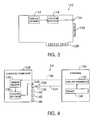
- FIG. 4is a block diagram illustrating an alternative embodiment of the system 10 .
- the system 10comprises a wireless transmitter 122 and a trigger 124 disposed in a peripheral 126
- a computer/component 128has a wireless receiver 130 and a controller or location indicator 132 .
- the peripheral 126also comprises a communication cable 134 having an end connector 136 for communicatively coupling the peripheral 126 to the computer/component 128 .
- the computer/component 128may comprise a plurality of connectors, such as connectors 138 , 140 , 142 , and 144 , one of which is the proper connector for the peripheral 126 and the end connector 136 .
- the trigger 124may be engaged for wirelessly transmitting a control signal 146 from the wireless transmitter 122 to the wireless receiver 130 , which then communicates the control signal 146 (or an appropriate command) to the location indicator 132 .
- the location indicator 132activates a user identifiable locator or light 148 adjacent the connector 138 , which is the proper connector for the peripheral 128 and the end connector 136 .
- the computer/component 128also may comprise a user identifiable locator or light, such as 148 , adjacent each one of the connectors 138 , 140 , 142 , and 144 .
- the control signal 146may comprise a variety of data or signals to identify the particular peripheral, bus type, connector, or user identifiable locator or light associated with the desired connection. For example, data may be acquired from the peripheral 126 for properly configuring the control signal 146 . The system then identifies and activates the appropriate one of the user identifiable locators or lights adjacent the proper one of the connectors 138 , 140 , 142 , and 144 .
- FIG. 5is a block diagram illustrating an alternative embodiment of the system 10 illustrated in FIG. 4 .
- the wireless transmitter 122 and the trigger 124are disposed in the end connector 136 of the cable 134 , rather than the peripheral 126 .
- the cable 134itself acts as the source of the control signal 146 to the wireless receiver 130 .
- a usermay engage the trigger 124 while searching for the proper one of the connectors 138 , 140 , 142 , and 144 on the computer/component 128 .
- the wireless transmitter 122sends the control signal 146 from the end connector 136 to the wireless receiver 130 , which then communicates the control signal 146 to the location indicator 132 .
- the location indicator 132then activates the user identifiable locator or light 148 adjacent the connector 138 , thereby guiding the user to connect the end connector 136 to the connector 138 .
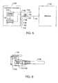
- FIG. 6is a side view illustrating an embodiment of the cable 134 illustrated in FIGS. 4 and 5 .
- the wireless transmitter 122is disposed within the end connector 136
- the trigger 124comprises a button 148 communicatively coupled to the wireless transmitter 122 .
- the wireless transmitter 122 and the trigger 124may be disposed within a connector module 150 , as illustrated by FIG. 7 .
- the connector module 150may be coupled to the end connector 136 as illustrated, or the connector module 150 may be coupled to a peripheral such as peripheral 126 .
- the connector module 150itself acts as the source of the control signal to the wireless receiver. Upon activation of the appropriate user identifiable locator, the desired cable connection can be completed.
Landscapes
- Engineering & Computer Science (AREA)
- Theoretical Computer Science (AREA)
- General Engineering & Computer Science (AREA)
- Human Computer Interaction (AREA)
- Physics & Mathematics (AREA)
- General Physics & Mathematics (AREA)
- Computer Hardware Design (AREA)
- Power Engineering (AREA)
- Details Of Connecting Devices For Male And Female Coupling (AREA)
Abstract
Description
Claims (29)
Priority Applications (1)
| Application Number | Priority Date | Filing Date | Title |
|---|---|---|---|
| US10/425,409US6857897B2 (en) | 2003-04-29 | 2003-04-29 | Remote cable assist |
Applications Claiming Priority (1)
| Application Number | Priority Date | Filing Date | Title |
|---|---|---|---|
| US10/425,409US6857897B2 (en) | 2003-04-29 | 2003-04-29 | Remote cable assist |
Publications (2)
| Publication Number | Publication Date |
|---|---|
| US20040219824A1 US20040219824A1 (en) | 2004-11-04 |
| US6857897B2true US6857897B2 (en) | 2005-02-22 |
Family
ID=33309689
Family Applications (1)
| Application Number | Title | Priority Date | Filing Date |
|---|---|---|---|
| US10/425,409Expired - LifetimeUS6857897B2 (en) | 2003-04-29 | 2003-04-29 | Remote cable assist |
Country Status (1)
| Country | Link |
|---|---|
| US (1) | US6857897B2 (en) |
Cited By (56)
| Publication number | Priority date | Publication date | Assignee | Title |
|---|---|---|---|---|
| US20050197017A1 (en)* | 2004-02-12 | 2005-09-08 | Super Talent Electronics Inc. | Extended secure-digital (SD) devices and hosts |
| US20050224585A1 (en)* | 2004-04-02 | 2005-10-13 | Durrant Richard C E | Radio frequency identification of a connector by a patch panel or other similar structure |
| US20060072271A1 (en)* | 2004-10-05 | 2006-04-06 | Ofi, Inc. | Electrical power distribution system |
| US20060094291A1 (en)* | 2004-11-03 | 2006-05-04 | Caveney Jack E | Method and apparatus for patch panel patch cord documentation and revision |
| US7104807B1 (en) | 2004-07-09 | 2006-09-12 | Super Talent Electronics, Inc. | Apparatus for an improved peripheral electronic interconnect device |
| US7104848B1 (en) | 2003-09-11 | 2006-09-12 | Super Talent Electronics, Inc. | Extended USB protocol plug and receptacle for implementing multi-mode communication |
| US7108560B1 (en)* | 2003-09-11 | 2006-09-19 | Super Talent Electronics, Inc. | Extended USB protocol plug and receptacle for implementing single-mode communication |
| US20060262727A1 (en)* | 2005-05-19 | 2006-11-23 | Panduit Corp. | Method and apparatus for documenting network paths |
| US20070032124A1 (en)* | 2005-08-08 | 2007-02-08 | Panduit Corp. | Systems and methods for detecting a patch cord end connection |
| US20070117444A1 (en)* | 2005-11-18 | 2007-05-24 | Panduit Corp. | Smart cable provisioning for a patch cord management system |
| US20070207666A1 (en)* | 2006-02-14 | 2007-09-06 | Panduit Corp. | Method and Apparatus for Patch Panel Patch Cord Documentation and Revision |
| US20070285239A1 (en)* | 2006-06-12 | 2007-12-13 | Easton Martyn N | Centralized optical-fiber-based RFID systems and methods |
| US20080049627A1 (en)* | 2005-06-14 | 2008-02-28 | Panduit Corp. | Method and Apparatus for Monitoring Physical Network Topology Information |
| US20080100467A1 (en)* | 2006-10-31 | 2008-05-01 | Downie John D | Radio frequency identification of component connections |
| US20080104275A1 (en)* | 2006-10-31 | 2008-05-01 | Jason Robert Almeida | Visual guidance and verification for interconnecting nodes |
| US20080100440A1 (en)* | 2006-10-31 | 2008-05-01 | Downie John D | Radio frequency identification transponder for communicating condition of a component |
| US20080143486A1 (en)* | 2006-12-14 | 2008-06-19 | Downie John D | Signal-processing systems and methods for RFID-tag signals |
| US7393247B1 (en) | 2005-03-08 | 2008-07-01 | Super Talent Electronics, Inc. | Architectures for external SATA-based flash memory devices |
| US20080218355A1 (en)* | 2007-03-09 | 2008-09-11 | Downie John D | Optically addressed RFID elements |
| US20090045961A1 (en)* | 2007-08-13 | 2009-02-19 | Aravind Chamarti | Antenna systems for passive RFID tags |
| US7510423B1 (en)* | 2004-07-13 | 2009-03-31 | Nvidia Corporation | Configurable lighted connector |
| US7519000B2 (en) | 2002-01-30 | 2009-04-14 | Panduit Corp. | Systems and methods for managing a network |
| US7563102B2 (en) | 2005-08-26 | 2009-07-21 | Panduit Corp. | Patch field documentation and revision systems |
| US20090190277A1 (en)* | 2007-09-28 | 2009-07-30 | Super Talent Electronics, Inc. | ESD Protection For USB Memory Devices |
| US20090258516A1 (en)* | 2007-07-05 | 2009-10-15 | Super Talent Electronics, Inc. | USB Device With Connected Cap |
| US20090316368A1 (en)* | 2007-07-05 | 2009-12-24 | Super Talent Electronics, Inc. | USB Package With Bistable Sliding Mechanism |
| US20100015847A1 (en)* | 2008-02-21 | 2010-01-21 | Panduit Corp. | Intelligent Inter-Connect and Cross-Connect Patching System |
| US7656903B2 (en) | 2002-01-30 | 2010-02-02 | Panduit Corp. | System and methods for documenting networks with electronic modules |
| US20100178058A1 (en)* | 2006-12-14 | 2010-07-15 | Kozischek David R | Rfid systems and methods for optical fiber network deployment and maintenance |
| US7768418B2 (en) | 2005-12-06 | 2010-08-03 | Panduit Corp. | Power patch panel with guided MAC capability |
| US7772975B2 (en) | 2006-10-31 | 2010-08-10 | Corning Cable Systems, Llc | System for mapping connections using RFID function |
| US20100245057A1 (en)* | 2009-03-31 | 2010-09-30 | Aravind Chamarti | Components, systems, and methods for associating sensor data with component location |
| US20110140856A1 (en)* | 2009-11-30 | 2011-06-16 | John David Downie | RFID Condition Latching |
| US7965186B2 (en) | 2007-03-09 | 2011-06-21 | Corning Cable Systems, Llc | Passive RFID elements having visual indicators |
| US7978845B2 (en) | 2005-09-28 | 2011-07-12 | Panduit Corp. | Powered patch panel |
| US8128428B2 (en) | 2009-02-19 | 2012-03-06 | Panduit Corp. | Cross connect patch guidance system |
| US8172468B2 (en) | 2010-05-06 | 2012-05-08 | Corning Incorporated | Radio frequency identification (RFID) in communication connections, including fiber optic components |
| US8248208B2 (en) | 2008-07-15 | 2012-08-21 | Corning Cable Systems, Llc. | RFID-based active labeling system for telecommunication systems |
| US8264355B2 (en) | 2006-12-14 | 2012-09-11 | Corning Cable Systems Llc | RFID systems and methods for optical fiber network deployment and maintenance |
| US8267706B2 (en) | 2008-11-12 | 2012-09-18 | Panduit Corp. | Patch cord with insertion detection and light illumination capabilities |
| US20120270436A1 (en)* | 2011-04-19 | 2012-10-25 | Blythe Stephen P | Identifying individual copper network cables on a patch panel |
| US20120274452A1 (en)* | 2011-04-26 | 2012-11-01 | Aravind Chamarti | Radio frequency (rf)-enabled latches and related components, assemblies, systems, and methods |
| US8306935B2 (en) | 2008-12-22 | 2012-11-06 | Panduit Corp. | Physical infrastructure management system |
| US8325770B2 (en) | 2003-08-06 | 2012-12-04 | Panduit Corp. | Network managed device installation and provisioning technique |
| US8477031B2 (en) | 2007-10-19 | 2013-07-02 | Panduit Corp. | Communication port identification system |
| CN102017325B (en)* | 2008-04-25 | 2013-11-06 | 索尼爱立信移动通讯有限公司 | Connector |
| US8625270B2 (en) | 1999-08-04 | 2014-01-07 | Super Talent Technology, Corp. | USB flash drive with deploying and retracting functionalities using retractable cover/cap |
| US8731405B2 (en) | 2008-08-28 | 2014-05-20 | Corning Cable Systems Llc | RFID-based systems and methods for collecting telecommunications network information |
| US9165232B2 (en) | 2012-05-14 | 2015-10-20 | Corning Incorporated | Radio-frequency identification (RFID) tag-to-tag autoconnect discovery, and related methods, circuits, and systems |
| US9176923B2 (en) | 2010-12-17 | 2015-11-03 | Lenovo Enterprise Solutions (Singapore) Pte. Ltd. | Electronic guidance for restoring a predetermined cabling configuration |
| US9461428B2 (en) | 2012-03-08 | 2016-10-04 | Nvidia Corporation | Low-cost offset stacked power connector |
| US9563832B2 (en) | 2012-10-08 | 2017-02-07 | Corning Incorporated | Excess radio-frequency (RF) power storage and power sharing RF identification (RFID) tags, and related connection systems and methods |
| US9652707B2 (en) | 2006-10-31 | 2017-05-16 | Fiber Mountain, Inc. | Radio frequency identification (RFID) connected tag communications protocol and related systems and methods |
| US9652709B2 (en) | 2006-10-31 | 2017-05-16 | Fiber Mountain, Inc. | Communications between multiple radio frequency identification (RFID) connected tags and one or more devices, and related systems and methods |
| US9652708B2 (en) | 2006-10-31 | 2017-05-16 | Fiber Mountain, Inc. | Protocol for communications between a radio frequency identification (RFID) tag and a connected device, and related systems and methods |
| US10032102B2 (en) | 2006-10-31 | 2018-07-24 | Fiber Mountain, Inc. | Excess radio-frequency (RF) power storage in RF identification (RFID) tags, and related systems and methods |
Families Citing this family (11)
| Publication number | Priority date | Publication date | Assignee | Title |
|---|---|---|---|---|
| FR2881910B1 (en)* | 2005-02-09 | 2007-05-25 | Eastman Kodak Co | SHOOTING EQUIPMENT AND IMAGE TRANSMISSION METHOD BY LOCAL NETWORK |
| US20080157978A1 (en)* | 2006-12-28 | 2008-07-03 | Motorola, Inc. | Method and system to aid users in installation of plug-in devices |
| US8208386B2 (en)* | 2007-03-05 | 2012-06-26 | Hewlett-Packard Development Company, L.P. | Discovery of network devices |
| US8102273B2 (en)* | 2008-12-14 | 2012-01-24 | International Business Machines Corporation | Guidance system by detecting tapped location |
| GB2505090A (en)* | 2011-05-05 | 2014-02-19 | Commscope Inc | Intelligent patching systems using acoustic control signals and related equipment and methods |
| US9022605B2 (en) | 2011-09-08 | 2015-05-05 | Irving E. Bushnell | Charging connection device with illumination and associated methods |
| CN103135789B (en)* | 2011-11-30 | 2016-10-19 | 原相科技股份有限公司 | Optical navigation device and its transmission interface with fast reading mechanism |
| US9400538B2 (en)* | 2013-09-13 | 2016-07-26 | Dell Products L.P. | Information handling system docking with cable based power and video management |
| US10554695B2 (en)* | 2015-03-25 | 2020-02-04 | Dell Products L.P. | Networked device connection system |
| US9924241B2 (en)* | 2015-07-30 | 2018-03-20 | Commscope, Inc. Of North Carolina | Intelligent patching systems and methods using color identification tags and related equipment |
| WO2020119885A1 (en)* | 2018-12-10 | 2020-06-18 | Vestel Elektronik Sanayi Ve Ticaret A.S. | Electronic devices and method of operating electronic devices |
Citations (8)
| Publication number | Priority date | Publication date | Assignee | Title |
|---|---|---|---|---|
| US3440347A (en)* | 1966-02-02 | 1969-04-22 | Spenko Intern Inc | Remote control plug-in unit |
| US4365238A (en)* | 1979-06-08 | 1982-12-21 | Adam Kollin | Visual signalling apparatus |
| US5095277A (en)* | 1989-02-13 | 1992-03-10 | Aerospatiale Societe Nationale Industrielle | System to test wiring parts |
| US5493618A (en)* | 1993-05-07 | 1996-02-20 | Joseph Enterprises | Method and apparatus for activating switches in response to different acoustic signals |
| US5910776A (en)* | 1994-10-24 | 1999-06-08 | Id Technologies, Inc. | Method and apparatus for identifying locating or monitoring equipment or other objects |
| US6445087B1 (en)* | 2000-06-23 | 2002-09-03 | Primax Electronics Ltd. | Networking power plug device with automated power outlet control |
| US6688910B1 (en)* | 1999-02-10 | 2004-02-10 | Avaya Technology Corp. | System and method for automatic addressing of devices in a dedicated telecommunications system |
| US6759966B1 (en)* | 2000-09-01 | 2004-07-06 | Linsong Weng | Wireless remote control bulb device |
- 2003
- 2003-04-29USUS10/425,409patent/US6857897B2/ennot_activeExpired - Lifetime
Patent Citations (8)
| Publication number | Priority date | Publication date | Assignee | Title |
|---|---|---|---|---|
| US3440347A (en)* | 1966-02-02 | 1969-04-22 | Spenko Intern Inc | Remote control plug-in unit |
| US4365238A (en)* | 1979-06-08 | 1982-12-21 | Adam Kollin | Visual signalling apparatus |
| US5095277A (en)* | 1989-02-13 | 1992-03-10 | Aerospatiale Societe Nationale Industrielle | System to test wiring parts |
| US5493618A (en)* | 1993-05-07 | 1996-02-20 | Joseph Enterprises | Method and apparatus for activating switches in response to different acoustic signals |
| US5910776A (en)* | 1994-10-24 | 1999-06-08 | Id Technologies, Inc. | Method and apparatus for identifying locating or monitoring equipment or other objects |
| US6688910B1 (en)* | 1999-02-10 | 2004-02-10 | Avaya Technology Corp. | System and method for automatic addressing of devices in a dedicated telecommunications system |
| US6445087B1 (en)* | 2000-06-23 | 2002-09-03 | Primax Electronics Ltd. | Networking power plug device with automated power outlet control |
| US6759966B1 (en)* | 2000-09-01 | 2004-07-06 | Linsong Weng | Wireless remote control bulb device |
Cited By (103)
| Publication number | Priority date | Publication date | Assignee | Title |
|---|---|---|---|---|
| US8625270B2 (en) | 1999-08-04 | 2014-01-07 | Super Talent Technology, Corp. | USB flash drive with deploying and retracting functionalities using retractable cover/cap |
| US7519000B2 (en) | 2002-01-30 | 2009-04-14 | Panduit Corp. | Systems and methods for managing a network |
| US7656903B2 (en) | 2002-01-30 | 2010-02-02 | Panduit Corp. | System and methods for documenting networks with electronic modules |
| US8325770B2 (en) | 2003-08-06 | 2012-12-04 | Panduit Corp. | Network managed device installation and provisioning technique |
| US7182646B1 (en)* | 2003-09-11 | 2007-02-27 | Super Talent Electronics, Inc. | Connectors having a USB-like form factor for supporting USB and non-USB protocols |
| US7427217B2 (en) | 2003-09-11 | 2008-09-23 | Super Talent Electronics, Inc. | Extended UBS protocol connector and socket |
| US7104848B1 (en) | 2003-09-11 | 2006-09-12 | Super Talent Electronics, Inc. | Extended USB protocol plug and receptacle for implementing multi-mode communication |
| US7108560B1 (en)* | 2003-09-11 | 2006-09-19 | Super Talent Electronics, Inc. | Extended USB protocol plug and receptacle for implementing single-mode communication |
| US7125287B1 (en)* | 2003-09-11 | 2006-10-24 | Super Talent Electronics, Inc. | Extended USB protocol plug and receptacle |
| US20060294272A1 (en)* | 2003-09-11 | 2006-12-28 | Horng-Yee Chou | Extended usb protocol connector and socket for implementing multi-mode communication |
| US7186147B1 (en) | 2003-09-11 | 2007-03-06 | Super Talent Electronics, Inc. | Peripheral device having an extended USB plug for communicating with a host computer |
| US7934037B2 (en) | 2004-02-12 | 2011-04-26 | Super Talent Electronics, Inc. | Extended Secure-Digital (SD) devices and hosts |
| US7836236B2 (en) | 2004-02-12 | 2010-11-16 | Super Talent Electronics, Inc. | Extended secure-digital (SD) devices and hosts |
| US20050197017A1 (en)* | 2004-02-12 | 2005-09-08 | Super Talent Electronics Inc. | Extended secure-digital (SD) devices and hosts |
| US20050224585A1 (en)* | 2004-04-02 | 2005-10-13 | Durrant Richard C E | Radio frequency identification of a connector by a patch panel or other similar structure |
| US7104807B1 (en) | 2004-07-09 | 2006-09-12 | Super Talent Electronics, Inc. | Apparatus for an improved peripheral electronic interconnect device |
| US7510423B1 (en)* | 2004-07-13 | 2009-03-31 | Nvidia Corporation | Configurable lighted connector |
| US8000074B2 (en) | 2004-10-05 | 2011-08-16 | 2D2C, Inc. | Electrical power distribution system |
| US20060072271A1 (en)* | 2004-10-05 | 2006-04-06 | Ofi, Inc. | Electrical power distribution system |
| US7517243B2 (en) | 2004-11-03 | 2009-04-14 | Panduit Corp. | Method and apparatus for patch panel patch cord documentation and revision |
| US7297018B2 (en) | 2004-11-03 | 2007-11-20 | Panduit Corp. | Method and apparatus for patch panel patch cord documentation and revision |
| US20060094291A1 (en)* | 2004-11-03 | 2006-05-04 | Caveney Jack E | Method and apparatus for patch panel patch cord documentation and revision |
| US7393247B1 (en) | 2005-03-08 | 2008-07-01 | Super Talent Electronics, Inc. | Architectures for external SATA-based flash memory devices |
| US20060262727A1 (en)* | 2005-05-19 | 2006-11-23 | Panduit Corp. | Method and apparatus for documenting network paths |
| US7756047B2 (en) | 2005-05-19 | 2010-07-13 | Panduit Corp. | Method and apparatus for documenting network paths |
| US7613124B2 (en) | 2005-05-19 | 2009-11-03 | Panduit Corp. | Method and apparatus for documenting network paths |
| US20080049627A1 (en)* | 2005-06-14 | 2008-02-28 | Panduit Corp. | Method and Apparatus for Monitoring Physical Network Topology Information |
| US8482421B2 (en) | 2005-08-08 | 2013-07-09 | Panduit Corp. | Systems and methods for detecting a patch cord end connection |
| US7969320B2 (en) | 2005-08-08 | 2011-06-28 | Panduit Corp. | Systems and methods for detecting a patch cord end connection |
| US20110234416A1 (en)* | 2005-08-08 | 2011-09-29 | Panduit Corp. | Systems and Methods for Detecting a Patch Cord End Connection |
| US20070032124A1 (en)* | 2005-08-08 | 2007-02-08 | Panduit Corp. | Systems and methods for detecting a patch cord end connection |
| US7636050B2 (en) | 2005-08-08 | 2009-12-22 | Panduit Corp. | Systems and methods for detecting a patch cord end connection |
| US7563102B2 (en) | 2005-08-26 | 2009-07-21 | Panduit Corp. | Patch field documentation and revision systems |
| US9049499B2 (en) | 2005-08-26 | 2015-06-02 | Panduit Corp. | Patch field documentation and revision systems |
| US7978845B2 (en) | 2005-09-28 | 2011-07-12 | Panduit Corp. | Powered patch panel |
| US7811119B2 (en) | 2005-11-18 | 2010-10-12 | Panduit Corp. | Smart cable provisioning for a patch cord management system |
| US20070117444A1 (en)* | 2005-11-18 | 2007-05-24 | Panduit Corp. | Smart cable provisioning for a patch cord management system |
| US7768418B2 (en) | 2005-12-06 | 2010-08-03 | Panduit Corp. | Power patch panel with guided MAC capability |
| US7488206B2 (en) | 2006-02-14 | 2009-02-10 | Panduit Corp. | Method and apparatus for patch panel patch cord documentation and revision |
| US20070207666A1 (en)* | 2006-02-14 | 2007-09-06 | Panduit Corp. | Method and Apparatus for Patch Panel Patch Cord Documentation and Revision |
| US7534137B2 (en) | 2006-02-14 | 2009-05-19 | Panduit Corp. | Method and apparatus for patch panel patch cord documentation and revision |
| US20070285239A1 (en)* | 2006-06-12 | 2007-12-13 | Easton Martyn N | Centralized optical-fiber-based RFID systems and methods |
| US9652707B2 (en) | 2006-10-31 | 2017-05-16 | Fiber Mountain, Inc. | Radio frequency identification (RFID) connected tag communications protocol and related systems and methods |
| US9652709B2 (en) | 2006-10-31 | 2017-05-16 | Fiber Mountain, Inc. | Communications between multiple radio frequency identification (RFID) connected tags and one or more devices, and related systems and methods |
| US20080100440A1 (en)* | 2006-10-31 | 2008-05-01 | Downie John D | Radio frequency identification transponder for communicating condition of a component |
| US8421626B2 (en) | 2006-10-31 | 2013-04-16 | Corning Cable Systems, Llc | Radio frequency identification transponder for communicating condition of a component |
| US7772975B2 (en) | 2006-10-31 | 2010-08-10 | Corning Cable Systems, Llc | System for mapping connections using RFID function |
| US7782202B2 (en) | 2006-10-31 | 2010-08-24 | Corning Cable Systems, Llc | Radio frequency identification of component connections |
| US20080104275A1 (en)* | 2006-10-31 | 2008-05-01 | Jason Robert Almeida | Visual guidance and verification for interconnecting nodes |
| US10032102B2 (en) | 2006-10-31 | 2018-07-24 | Fiber Mountain, Inc. | Excess radio-frequency (RF) power storage in RF identification (RFID) tags, and related systems and methods |
| US20080100467A1 (en)* | 2006-10-31 | 2008-05-01 | Downie John D | Radio frequency identification of component connections |
| US9652708B2 (en) | 2006-10-31 | 2017-05-16 | Fiber Mountain, Inc. | Protocol for communications between a radio frequency identification (RFID) tag and a connected device, and related systems and methods |
| EP2089865A4 (en)* | 2006-10-31 | 2015-07-15 | Corning Cable Sys Llc | Radio frequency identification transponder for communicating condition of a component |
| WO2008054730A2 (en) | 2006-10-31 | 2008-05-08 | Corning Cable Systems Llc | Radio frequency identification transponder for communicating condition of a component |
| US8264355B2 (en) | 2006-12-14 | 2012-09-11 | Corning Cable Systems Llc | RFID systems and methods for optical fiber network deployment and maintenance |
| US20100178058A1 (en)* | 2006-12-14 | 2010-07-15 | Kozischek David R | Rfid systems and methods for optical fiber network deployment and maintenance |
| US7667574B2 (en) | 2006-12-14 | 2010-02-23 | Corning Cable Systems, Llc | Signal-processing systems and methods for RFID-tag signals |
| US7760094B1 (en) | 2006-12-14 | 2010-07-20 | Corning Cable Systems Llc | RFID systems and methods for optical fiber network deployment and maintenance |
| US20080143486A1 (en)* | 2006-12-14 | 2008-06-19 | Downie John D | Signal-processing systems and methods for RFID-tag signals |
| US7547150B2 (en) | 2007-03-09 | 2009-06-16 | Corning Cable Systems, Llc | Optically addressed RFID elements |
| US7965186B2 (en) | 2007-03-09 | 2011-06-21 | Corning Cable Systems, Llc | Passive RFID elements having visual indicators |
| US20080218355A1 (en)* | 2007-03-09 | 2008-09-11 | Downie John D | Optically addressed RFID elements |
| US20090316368A1 (en)* | 2007-07-05 | 2009-12-24 | Super Talent Electronics, Inc. | USB Package With Bistable Sliding Mechanism |
| US8102662B2 (en) | 2007-07-05 | 2012-01-24 | Super Talent Electronics, Inc. | USB package with bistable sliding mechanism |
| US20090258516A1 (en)* | 2007-07-05 | 2009-10-15 | Super Talent Electronics, Inc. | USB Device With Connected Cap |
| US20100248512A1 (en)* | 2007-07-05 | 2010-09-30 | Super Talent Electronics, Inc. | USB Device With Connected Cap |
| US7855697B2 (en) | 2007-08-13 | 2010-12-21 | Corning Cable Systems, Llc | Antenna systems for passive RFID tags |
| US20090045961A1 (en)* | 2007-08-13 | 2009-02-19 | Aravind Chamarti | Antenna systems for passive RFID tags |
| US20090190277A1 (en)* | 2007-09-28 | 2009-07-30 | Super Talent Electronics, Inc. | ESD Protection For USB Memory Devices |
| US8477031B2 (en) | 2007-10-19 | 2013-07-02 | Panduit Corp. | Communication port identification system |
| US8246397B2 (en)* | 2008-02-21 | 2012-08-21 | Panduit Corp. | Intelligent inter-connect and cross-connect patching system |
| US8419465B2 (en) | 2008-02-21 | 2013-04-16 | Panduit Corp. | Intelligent inter-connect and cross-connect patching system |
| US8715001B2 (en) | 2008-02-21 | 2014-05-06 | Panduit Corp. | Intelligent inter-connect and cross-connect patching system |
| US20110244698A1 (en)* | 2008-02-21 | 2011-10-06 | Panduit Corp. | Intelligent Inter-Connect and Cross-Connect Patching System |
| US20100015847A1 (en)* | 2008-02-21 | 2010-01-21 | Panduit Corp. | Intelligent Inter-Connect and Cross-Connect Patching System |
| US9866458B2 (en) | 2008-02-21 | 2018-01-09 | Panduit Corp. | Intelligent inter-connect and cross-connect patching system |
| US7938700B2 (en) | 2008-02-21 | 2011-05-10 | Panduit Corp. | Intelligent inter-connect and cross-connect patching system |
| CN102017325B (en)* | 2008-04-25 | 2013-11-06 | 索尼爱立信移动通讯有限公司 | Connector |
| US8248208B2 (en) | 2008-07-15 | 2012-08-21 | Corning Cable Systems, Llc. | RFID-based active labeling system for telecommunication systems |
| US9058529B2 (en) | 2008-08-28 | 2015-06-16 | Corning Optical Communications LLC | RFID-based systems and methods for collecting telecommunications network information |
| US8731405B2 (en) | 2008-08-28 | 2014-05-20 | Corning Cable Systems Llc | RFID-based systems and methods for collecting telecommunications network information |
| US8414319B2 (en) | 2008-11-12 | 2013-04-09 | Panduit Corp. | Patch cord with insertion detection and light illumination capabilities |
| US8267706B2 (en) | 2008-11-12 | 2012-09-18 | Panduit Corp. | Patch cord with insertion detection and light illumination capabilities |
| US8708724B2 (en) | 2008-11-12 | 2014-04-29 | Panduit Corp. | Patch cord insertion detection and light illumination capabilities |
| US9026486B2 (en) | 2008-12-22 | 2015-05-05 | Panduit Corp. | Physical infrastructure management system |
| US8719205B2 (en) | 2008-12-22 | 2014-05-06 | Panduit Corp. | Physical infrastructure management system |
| US10516580B2 (en) | 2008-12-22 | 2019-12-24 | Panduit Corp. | Physical infrastructure management system |
| US8306935B2 (en) | 2008-12-22 | 2012-11-06 | Panduit Corp. | Physical infrastructure management system |
| US8721360B2 (en) | 2009-02-19 | 2014-05-13 | Panduit Corp. | Methods for patch cord guidance |
| US8382511B2 (en) | 2009-02-19 | 2013-02-26 | Panduit Corp. | Cross connect patch guidance system |
| US8128428B2 (en) | 2009-02-19 | 2012-03-06 | Panduit Corp. | Cross connect patch guidance system |
| US8264366B2 (en) | 2009-03-31 | 2012-09-11 | Corning Incorporated | Components, systems, and methods for associating sensor data with component location |
| US20100245057A1 (en)* | 2009-03-31 | 2010-09-30 | Aravind Chamarti | Components, systems, and methods for associating sensor data with component location |
| US9159012B2 (en) | 2009-11-30 | 2015-10-13 | Corning Incorporated | RFID condition latching |
| US20110140856A1 (en)* | 2009-11-30 | 2011-06-16 | John David Downie | RFID Condition Latching |
| US8172468B2 (en) | 2010-05-06 | 2012-05-08 | Corning Incorporated | Radio frequency identification (RFID) in communication connections, including fiber optic components |
| US8333518B2 (en) | 2010-05-06 | 2012-12-18 | Corning Incorporated | Radio frequency identification (RFID) in communication connections, including fiber optic components |
| US9176923B2 (en) | 2010-12-17 | 2015-11-03 | Lenovo Enterprise Solutions (Singapore) Pte. Ltd. | Electronic guidance for restoring a predetermined cabling configuration |
| US20120270436A1 (en)* | 2011-04-19 | 2012-10-25 | Blythe Stephen P | Identifying individual copper network cables on a patch panel |
| US20120274452A1 (en)* | 2011-04-26 | 2012-11-01 | Aravind Chamarti | Radio frequency (rf)-enabled latches and related components, assemblies, systems, and methods |
| US9461428B2 (en) | 2012-03-08 | 2016-10-04 | Nvidia Corporation | Low-cost offset stacked power connector |
| US9165232B2 (en) | 2012-05-14 | 2015-10-20 | Corning Incorporated | Radio-frequency identification (RFID) tag-to-tag autoconnect discovery, and related methods, circuits, and systems |
| US9563832B2 (en) | 2012-10-08 | 2017-02-07 | Corning Incorporated | Excess radio-frequency (RF) power storage and power sharing RF identification (RFID) tags, and related connection systems and methods |
Also Published As
| Publication number | Publication date |
|---|---|
| US20040219824A1 (en) | 2004-11-04 |
Similar Documents
| Publication | Publication Date | Title |
|---|---|---|
| US6857897B2 (en) | Remote cable assist | |
| US6946988B2 (en) | Detachable remote controller for an electronic entertainment device and a method for using the same | |
| US5305449A (en) | Keycode/pointing device conversion adapter which converts mouse motion signals into cursor signals by activating keyboard cursor keys | |
| US8147332B2 (en) | Method of indicating the ordinal number of a player in a wireless gaming system | |
| US7354275B2 (en) | Graphics card connector module, and motherboard device having the same | |
| EP1772965A2 (en) | Electronic device and control method thereof | |
| CN1267417A (en) | Apparatus for enabling and disabling wireless communication device incorporated within mobile computer | |
| US9201650B2 (en) | Super I/O module and control method thereof | |
| WO2004025320A1 (en) | Multi-mode gps receiver | |
| US20100265644A1 (en) | Interface card socket and circuit board module having the same | |
| US6850417B2 (en) | Integrated expansion card slot status indicator and power actuator | |
| CN104297871A (en) | Optical fiber interconnecting system and method | |
| CN101432676A (en) | Computing device antenna identification system and method | |
| US9627789B2 (en) | Module compatibility indication system | |
| US20090240844A1 (en) | Method for adding hardware | |
| KR20130031188A (en) | Electric device with multiple data connection ports | |
| US6662259B1 (en) | Modularized universal serial bus hub | |
| US20120300380A1 (en) | Laptop computer with manually operated switch for diverting key codes to bluetooth device communication module | |
| US6836807B2 (en) | Wireless receiving device and method jointly used by computer peripherals | |
| US20200110718A1 (en) | Hardware component detections | |
| CN103034600A (en) | Electronic device with multiple data connection ports | |
| US6805293B2 (en) | Data collection system | |
| US20040049611A1 (en) | Flexible serial port configuration and method | |
| US9768861B2 (en) | Input device and short-range wireless communication converter thereof | |
| JP2010097712A (en) | Connector connection device, connector insertion-extraction tool, and connector insertion-extraction management system |
Legal Events
| Date | Code | Title | Description |
|---|---|---|---|
| AS | Assignment | Owner name:HEWLETT-PACKARD DEVELOPMENT COMPANY, L.P., TEXAS Free format text:ASSIGNMENT OF ASSIGNORS INTEREST;ASSIGNOR:CONN, KEVIN D.;REEL/FRAME:013830/0467 Effective date:20030428 | |
| STCF | Information on status: patent grant | Free format text:PATENTED CASE | |
| FPAY | Fee payment | Year of fee payment:4 | |
| REMI | Maintenance fee reminder mailed | ||
| FPAY | Fee payment | Year of fee payment:8 | |
| AS | Assignment | Owner name:HEWLETT PACKARD ENTERPRISE DEVELOPMENT LP, TEXAS Free format text:ASSIGNMENT OF ASSIGNORS INTEREST;ASSIGNOR:HEWLETT-PACKARD DEVELOPMENT COMPANY, L.P.;REEL/FRAME:037079/0001 Effective date:20151027 | |
| REMI | Maintenance fee reminder mailed | ||
| FPAY | Fee payment | Year of fee payment:12 | |
| SULP | Surcharge for late payment | Year of fee payment:11 | |
| AS | Assignment | Owner name:OT PATENT ESCROW, LLC, ILLINOIS Free format text:PATENT ASSIGNMENT, SECURITY INTEREST, AND LIEN AGREEMENT;ASSIGNORS:HEWLETT PACKARD ENTERPRISE DEVELOPMENT LP;HEWLETT PACKARD ENTERPRISE COMPANY;REEL/FRAME:055269/0001 Effective date:20210115 | |
| AS | Assignment | Owner name:VALTRUS INNOVATIONS LIMITED, IRELAND Free format text:ASSIGNMENT OF ASSIGNORS INTEREST;ASSIGNOR:OT PATENT ESCROW, LLC;REEL/FRAME:056157/0492 Effective date:20210503 |