US6856827B2 - Fluoroscopic tracking and visualization system - Google Patents
Fluoroscopic tracking and visualization systemDownload PDFInfo
- Publication number
- US6856827B2 US6856827B2US10/308,340US30834002AUS6856827B2US 6856827 B2US6856827 B2US 6856827B2US 30834002 AUS30834002 AUS 30834002AUS 6856827 B2US6856827 B2US 6856827B2
- Authority
- US
- United States
- Prior art keywords
- image
- tracking
- fluoroscope
- markers
- tool
- Prior art date
- Legal status (The legal status is an assumption and is not a legal conclusion. Google has not performed a legal analysis and makes no representation as to the accuracy of the status listed.)
- Expired - Lifetime, expires
Links
- 238000012800visualizationMethods0.000title1
- 238000003384imaging methodMethods0.000claimsabstractdescription48
- 230000033001locomotionEffects0.000claimsabstractdescription14
- 238000005259measurementMethods0.000claimsabstractdescription10
- 238000001356surgical procedureMethods0.000claimsabstractdescription10
- 239000003550markerSubstances0.000claimsdescription53
- 230000009466transformationEffects0.000claimsdescription13
- 238000012937correctionMethods0.000claimsdescription9
- 238000003491arrayMethods0.000claimsdescription8
- 238000000926separation methodMethods0.000claimsdescription4
- 238000002059diagnostic imagingMethods0.000claims8
- 238000000034methodMethods0.000description38
- 230000003287optical effectEffects0.000description31
- 210000001519tissueAnatomy0.000description23
- 238000012545processingMethods0.000description12
- 238000004422calculation algorithmMethods0.000description10
- 230000008569processEffects0.000description10
- 239000000523sampleSubstances0.000description8
- 238000001514detection methodMethods0.000description6
- 239000000463materialSubstances0.000description6
- 210000003484anatomyAnatomy0.000description5
- 230000000875corresponding effectEffects0.000description5
- 125000001153fluoro groupChemical groupF*0.000description5
- 238000000844transformationMethods0.000description5
- 210000000988bone and boneAnatomy0.000description4
- 239000011159matrix materialSubstances0.000description4
- 239000013598vectorSubstances0.000description4
- 238000010521absorption reactionMethods0.000description3
- 238000013459approachMethods0.000description3
- 230000000712assemblyEffects0.000description3
- 238000000429assemblyMethods0.000description3
- 210000004556brainAnatomy0.000description3
- 238000009826distributionMethods0.000description3
- 230000005672electromagnetic fieldEffects0.000description3
- 229920000642polymerPolymers0.000description3
- 239000004616structural foamSubstances0.000description3
- OAICVXFJPJFONN-UHFFFAOYSA-NPhosphorusChemical compound[P]OAICVXFJPJFONN-UHFFFAOYSA-N0.000description2
- 238000004458analytical methodMethods0.000description2
- 238000005452bendingMethods0.000description2
- 238000001574biopsyMethods0.000description2
- 230000002596correlated effectEffects0.000description2
- 230000000694effectsEffects0.000description2
- 238000012986modificationMethods0.000description2
- 230000004048modificationEffects0.000description2
- 230000005405multipoleEffects0.000description2
- 238000003909pattern recognitionMethods0.000description2
- 230000005855radiationEffects0.000description2
- 230000011664signalingEffects0.000description2
- 229920004142LEXAN™Polymers0.000description1
- 239000004418LexanSubstances0.000description1
- 206010028980NeoplasmDiseases0.000description1
- 238000000333X-ray scatteringMethods0.000description1
- 238000002835absorbanceMethods0.000description1
- NIXOWILDQLNWCW-UHFFFAOYSA-Nacrylic acid groupChemical groupC(C=C)(=O)ONIXOWILDQLNWCW-UHFFFAOYSA-N0.000description1
- 238000002583angiographyMethods0.000description1
- 230000015572biosynthetic processEffects0.000description1
- 238000004364calculation methodMethods0.000description1
- 230000000747cardiac effectEffects0.000description1
- 238000002591computed tomographyMethods0.000description1
- 238000013170computed tomography imagingMethods0.000description1
- 238000005094computer simulationMethods0.000description1
- 238000010276constructionMethods0.000description1
- 230000001186cumulative effectEffects0.000description1
- 230000003247decreasing effectEffects0.000description1
- 238000007435diagnostic evaluationMethods0.000description1
- 238000010586diagramMethods0.000description1
- 238000005553drillingMethods0.000description1
- 239000006260foamSubstances0.000description1
- 239000003574free electronSubstances0.000description1
- 238000003702image correctionMethods0.000description1
- 238000003780insertionMethods0.000description1
- 230000037431insertionEffects0.000description1
- 238000002697interventional radiologyMethods0.000description1
- 230000001788irregularEffects0.000description1
- 210000003127kneeAnatomy0.000description1
- 238000001459lithographyMethods0.000description1
- 238000007726management methodMethods0.000description1
- 238000004519manufacturing processMethods0.000description1
- 230000007246mechanismEffects0.000description1
- 230000001404mediated effectEffects0.000description1
- 238000001465metallisationMethods0.000description1
- 238000001393microlithographyMethods0.000description1
- 238000005457optimizationMethods0.000description1
- 230000000737periodic effectEffects0.000description1
- 230000002093peripheral effectEffects0.000description1
- 238000002601radiographyMethods0.000description1
- 238000001454recorded imageMethods0.000description1
- 238000009877renderingMethods0.000description1
- 230000004044responseEffects0.000description1
- 238000007665saggingMethods0.000description1
- 239000004065semiconductorSubstances0.000description1
- 210000002832shoulderAnatomy0.000description1
- 210000004872soft tissueAnatomy0.000description1
- 239000008259solid foamSubstances0.000description1
- 229910001220stainless steelInorganic materials0.000description1
- 239000010935stainless steelSubstances0.000description1
- 239000000725suspensionSubstances0.000description1
- 238000003325tomographyMethods0.000description1
- 230000001131transforming effectEffects0.000description1
- 238000013519translationMethods0.000description1
- 230000000007visual effectEffects0.000description1
- 210000000707wristAnatomy0.000description1
Images


Classifications
- A—HUMAN NECESSITIES
- A61—MEDICAL OR VETERINARY SCIENCE; HYGIENE
- A61B—DIAGNOSIS; SURGERY; IDENTIFICATION
- A61B6/00—Apparatus or devices for radiation diagnosis; Apparatus or devices for radiation diagnosis combined with radiation therapy equipment
- A61B6/52—Devices using data or image processing specially adapted for radiation diagnosis
- A61B6/5211—Devices using data or image processing specially adapted for radiation diagnosis involving processing of medical diagnostic data
- A61B6/5229—Devices using data or image processing specially adapted for radiation diagnosis involving processing of medical diagnostic data combining image data of a patient, e.g. combining a functional image with an anatomical image
- A61B6/5247—Devices using data or image processing specially adapted for radiation diagnosis involving processing of medical diagnostic data combining image data of a patient, e.g. combining a functional image with an anatomical image combining images from an ionising-radiation diagnostic technique and a non-ionising radiation diagnostic technique, e.g. X-ray and ultrasound
- A—HUMAN NECESSITIES
- A61—MEDICAL OR VETERINARY SCIENCE; HYGIENE
- A61B—DIAGNOSIS; SURGERY; IDENTIFICATION
- A61B34/00—Computer-aided surgery; Manipulators or robots specially adapted for use in surgery
- A61B34/20—Surgical navigation systems; Devices for tracking or guiding surgical instruments, e.g. for frameless stereotaxis
- A—HUMAN NECESSITIES
- A61—MEDICAL OR VETERINARY SCIENCE; HYGIENE
- A61B—DIAGNOSIS; SURGERY; IDENTIFICATION
- A61B6/00—Apparatus or devices for radiation diagnosis; Apparatus or devices for radiation diagnosis combined with radiation therapy equipment
- A61B6/12—Arrangements for detecting or locating foreign bodies
- A—HUMAN NECESSITIES
- A61—MEDICAL OR VETERINARY SCIENCE; HYGIENE
- A61B—DIAGNOSIS; SURGERY; IDENTIFICATION
- A61B6/00—Apparatus or devices for radiation diagnosis; Apparatus or devices for radiation diagnosis combined with radiation therapy equipment
- A61B6/44—Constructional features of apparatus for radiation diagnosis
- A61B6/4429—Constructional features of apparatus for radiation diagnosis related to the mounting of source units and detector units
- A61B6/4435—Constructional features of apparatus for radiation diagnosis related to the mounting of source units and detector units the source unit and the detector unit being coupled by a rigid structure
- A61B6/4441—Constructional features of apparatus for radiation diagnosis related to the mounting of source units and detector units the source unit and the detector unit being coupled by a rigid structure the rigid structure being a C-arm or U-arm
- A—HUMAN NECESSITIES
- A61—MEDICAL OR VETERINARY SCIENCE; HYGIENE
- A61B—DIAGNOSIS; SURGERY; IDENTIFICATION
- A61B6/00—Apparatus or devices for radiation diagnosis; Apparatus or devices for radiation diagnosis combined with radiation therapy equipment
- A61B6/46—Arrangements for interfacing with the operator or the patient
- A61B6/461—Displaying means of special interest
- A61B6/465—Displaying means of special interest adapted to display user selection data, e.g. graphical user interface, icons or menus
- A—HUMAN NECESSITIES
- A61—MEDICAL OR VETERINARY SCIENCE; HYGIENE
- A61B—DIAGNOSIS; SURGERY; IDENTIFICATION
- A61B6/00—Apparatus or devices for radiation diagnosis; Apparatus or devices for radiation diagnosis combined with radiation therapy equipment
- A61B6/48—Diagnostic techniques
- A61B6/486—Diagnostic techniques involving generating temporal series of image data
- A61B6/487—Diagnostic techniques involving generating temporal series of image data involving fluoroscopy
- A—HUMAN NECESSITIES
- A61—MEDICAL OR VETERINARY SCIENCE; HYGIENE
- A61B—DIAGNOSIS; SURGERY; IDENTIFICATION
- A61B6/00—Apparatus or devices for radiation diagnosis; Apparatus or devices for radiation diagnosis combined with radiation therapy equipment
- A61B6/52—Devices using data or image processing specially adapted for radiation diagnosis
- A61B6/5211—Devices using data or image processing specially adapted for radiation diagnosis involving processing of medical diagnostic data
- A61B6/5229—Devices using data or image processing specially adapted for radiation diagnosis involving processing of medical diagnostic data combining image data of a patient, e.g. combining a functional image with an anatomical image
- A61B6/5235—Devices using data or image processing specially adapted for radiation diagnosis involving processing of medical diagnostic data combining image data of a patient, e.g. combining a functional image with an anatomical image combining images from the same or different ionising radiation imaging techniques, e.g. PET and CT
- A—HUMAN NECESSITIES
- A61—MEDICAL OR VETERINARY SCIENCE; HYGIENE
- A61B—DIAGNOSIS; SURGERY; IDENTIFICATION
- A61B6/00—Apparatus or devices for radiation diagnosis; Apparatus or devices for radiation diagnosis combined with radiation therapy equipment
- A61B6/54—Control of apparatus or devices for radiation diagnosis
- A61B6/547—Control of apparatus or devices for radiation diagnosis involving tracking of position of the device or parts of the device
- A—HUMAN NECESSITIES
- A61—MEDICAL OR VETERINARY SCIENCE; HYGIENE
- A61B—DIAGNOSIS; SURGERY; IDENTIFICATION
- A61B6/00—Apparatus or devices for radiation diagnosis; Apparatus or devices for radiation diagnosis combined with radiation therapy equipment
- A61B6/58—Testing, adjusting or calibrating thereof
- A61B6/582—Calibration
- A61B6/583—Calibration using calibration phantoms
- A61B6/584—Calibration using calibration phantoms determining position of components of the apparatus or device using images of the phantom
- A—HUMAN NECESSITIES
- A61—MEDICAL OR VETERINARY SCIENCE; HYGIENE
- A61B—DIAGNOSIS; SURGERY; IDENTIFICATION
- A61B90/00—Instruments, implements or accessories specially adapted for surgery or diagnosis and not covered by any of the groups A61B1/00 - A61B50/00, e.g. for luxation treatment or for protecting wound edges
- A61B90/36—Image-producing devices or illumination devices not otherwise provided for
- A—HUMAN NECESSITIES
- A61—MEDICAL OR VETERINARY SCIENCE; HYGIENE
- A61B—DIAGNOSIS; SURGERY; IDENTIFICATION
- A61B34/00—Computer-aided surgery; Manipulators or robots specially adapted for use in surgery
- A61B34/20—Surgical navigation systems; Devices for tracking or guiding surgical instruments, e.g. for frameless stereotaxis
- A61B2034/2046—Tracking techniques
- A61B2034/2051—Electromagnetic tracking systems
- A—HUMAN NECESSITIES
- A61—MEDICAL OR VETERINARY SCIENCE; HYGIENE
- A61B—DIAGNOSIS; SURGERY; IDENTIFICATION
- A61B34/00—Computer-aided surgery; Manipulators or robots specially adapted for use in surgery
- A61B34/20—Surgical navigation systems; Devices for tracking or guiding surgical instruments, e.g. for frameless stereotaxis
- A61B2034/2046—Tracking techniques
- A61B2034/2055—Optical tracking systems
- A—HUMAN NECESSITIES
- A61—MEDICAL OR VETERINARY SCIENCE; HYGIENE
- A61B—DIAGNOSIS; SURGERY; IDENTIFICATION
- A61B34/00—Computer-aided surgery; Manipulators or robots specially adapted for use in surgery
- A61B34/20—Surgical navigation systems; Devices for tracking or guiding surgical instruments, e.g. for frameless stereotaxis
- A61B2034/2072—Reference field transducer attached to an instrument or patient
- A—HUMAN NECESSITIES
- A61—MEDICAL OR VETERINARY SCIENCE; HYGIENE
- A61B—DIAGNOSIS; SURGERY; IDENTIFICATION
- A61B90/00—Instruments, implements or accessories specially adapted for surgery or diagnosis and not covered by any of the groups A61B1/00 - A61B50/00, e.g. for luxation treatment or for protecting wound edges
- A61B90/36—Image-producing devices or illumination devices not otherwise provided for
- A61B90/37—Surgical systems with images on a monitor during operation
- A61B2090/376—Surgical systems with images on a monitor during operation using X-rays, e.g. fluoroscopy
- A—HUMAN NECESSITIES
- A61—MEDICAL OR VETERINARY SCIENCE; HYGIENE
- A61B—DIAGNOSIS; SURGERY; IDENTIFICATION
- A61B5/00—Measuring for diagnostic purposes; Identification of persons
- A61B5/06—Devices, other than using radiation, for detecting or locating foreign bodies ; Determining position of diagnostic devices within or on the body of the patient
- A61B5/061—Determining position of a probe within the body employing means separate from the probe, e.g. sensing internal probe position employing impedance electrodes on the surface of the body
- A61B5/062—Determining position of a probe within the body employing means separate from the probe, e.g. sensing internal probe position employing impedance electrodes on the surface of the body using magnetic field
Definitions
- the present inventionrelates to medical and surgical imaging, and in particular to intraoperative or perioperative imaging in which images are formed of a region of the patient's body and a surgical tool or instrument is applied thereto, and the images aid in an ongoing procedure. It is of a special utility in surgical procedures such as brain surgery and arthroscopic procedures on the knee, wrist, shoulder or spine, as well as certain types of angiography, cardiac procedures, interventional radiology and biopsies in which x-ray images may be taken to display, correct the position of, or otherwise navigate a tool or instrument involved in the procedure.
- these previously recorded diagnostic image setsthemselves define a three dimensional rectilinear coordinate system, by virtue of their precision scan formation or the spatial mathematics of their reconstruction algorithms. However, it may be necessary to correlate the available fluoroscopic views and anatomical features visible from the surface or in fluoroscopic images with features in the 3-D diagnostic images and with the external coordinates of the tools being employed.
- imageable fiducialswhich may for example be imaged in both fluoroscopic and MRI or CT images
- systemscan also operate to a large extent with simple optical tracking of the surgical tool, and may employ an initialization protocol wherein the surgeon touches or points at a number of bony prominences or other recognizable anatomic features in order to define the external coordinates in relation to the patient anatomy and to initiate software tracking of those features.
- systems of this typeoperate with an image display which is positioned in the surgeon's field of view, and which displays a few panels such as a selected MRI image and several x-ray or fluoroscopic views taken from different angles.
- the three-dimensional diagnostic imagestypically have a spatial resolution that is both rectilinear and accurate to within a very small tolerance, e.g., to within one millimeter or less.
- the fluoroscopic viewsby contrast are distorted, and they are shadowgraphic in that they represent the density of all tissue through which the conical x-ray beam has passed.
- the display visible to the surgeonmay show an image of the surgical tool, biopsy instrument, pedicle screw, probe or the like projected onto a fluoroscopic image, so that the surgeon may visualize the orientation of the surgical instrument in relation to the imaged patient anatomy, while an appropriate reconstructed CT or MRI image, which may correspond to the tracked coordinates of the probe tip, is also displayed.
- the various sets of coordinatesmay be defined by robotic mechanical links and encoders, or more usually, are defined by a fixed patient support, two or more receivers such as video cameras which may be fixed to the support, and a plurality of signaling elements attached to a guide or frame on the surgical instrument that enable the position and orientation of the tool with respect to the patient support and camera frame to be automatically determined by triangulation, so that various transformations between respective coordinates may be computed.
- Three-dimensional tracking systems employing two video cameras and a plurality of emitters or other position signaling elementshave long been commercially available and are readily adapted to such operating room systems.
- Similar systemsmay also determine external position coordinates using commercially available acoustic ranging systems in which three or more acoustic emitters are actuated and their sounds detected at plural receivers to determine their relative distances from the detecting assemblies, and thus define by simple triangulation the position and orientation of the frames or supports on which the emitters are mounted.
- acoustic ranging systemsin which three or more acoustic emitters are actuated and their sounds detected at plural receivers to determine their relative distances from the detecting assemblies, and thus define by simple triangulation the position and orientation of the frames or supports on which the emitters are mounted.
- tracked fiducialsappear in the diagnostic images, it is possible to define a transformation between operating room coordinates and the coordinates of the image.
- Intraoperative x-ray images taken by C-arm fluoroscopesalone have both a high degree of distortion and a low degree of repeatability, due largely to deformations of the basic source and camera assembly, and to intrinsic variability of positioning and image distortion properties of the camera.
- intraoperative sterile fieldsuch devices must be draped, which may impair optical or acoustic signal paths of the signal elements they employ to track the patient, tool or camera.
- Correlation of patient anatomy or intraoperative fluoroscopic images with precompiled 3-D diagnostic image data setsmay also be complicated by intervening movement of the imaged structures, particularly soft tissue structures, between the times of original imaging and the intraoperative procedure.
- transformations between three or more coordinate systems for two sets of images and the physical coordinates in the operating roommay require a large number of registration points to provide an effective correlation.
- spinal tracking to position pedicle screwsit may be necessary to initialize the tracking assembly on ten or more points on a single vertebra to achieve suitable accuracy. In cases where a growing tumor or evolving condition actually changes the tissue dimension or position between imaging sessions, further confounding factors may appear.
- the registrationmay alternatively be effected without ongoing reference to tracking images, by using a computer modeling procedure in which a tool tip is touched to and initialized on each of several bony prominences to establish their coordinates and disposition, after which movement of the spine as a whole is modeled by optically initially registering and then tracking the tool in relation to the position of those prominences, while mechanically modeling a virtual representation of the spine with a tracking element or frame attached to the spine.
- Such a proceduredispenses with the time-consuming and computationally intensive correlation of different image sets from different sources, and, by substituting optical tracking of points, may eliminate or reduce the number of x-ray exposures required to effectively determine the tool position in relation to the patient anatomy with the required degree of precision.
- an x-ray imaging machine of movable angulationsuch as a fluoroscope
- a tracking systememploys a tracking element affixed to each of the imaging machine and tool, and preferably to the patient as well, to provide respective position data for the tool, the fluoroscope and patient, while a fixed volume array of markers, which is also tracked, is imaged in each frame.
- the array of markersis affixed to the detector assembly of the imaging machine, where a single tracking element determines position of the fluoroscope and entire array of markers.
- the fluoroscopemay itself also provide further shot-specific indexing or identification data of conventional type, such as time, settings or the like.
- a processorthen applies the position data from the tracking system, and operates on the imaged markers to produce a correct tool navigation image for surgical guidance.
- the markersare preferably arranged in a known pattern of substantially non-shadowing point elements positioned in different planes. These may be rigidly spaced apart in a predefined configuration in an assembly attached to the fluoroscope, so that the physical position of each marker is known exactly in a fixed fluoroscope-based coordinate system, and the positions may, for example, be stored in a table.
- a single tracking elementmay be affixed on the marker assembly, which may in turn be locked in a fixed position on the fluoroscope, so that the fluoroscope and marker positions are known in relation to the tool and the patient.
- one or more separate arrays of markersmay be independently positioned and each tracked by a separate tracking element.
- the processoridentifies a subset of the markers and recovers geometric camera calibration parameters from the imaged marker positions. These calibration parameters then allow accurate reference between the recorded image and the tool and patient coordinates measured by the trackers.
- the processormay also receive patient identification data of a conventional type to display or record with the shot.
- the processorcomputes the calibration as well as geometric distortion due to the imaging process, and converts the tracked or actual location of the tool to a distorted tool image position at which the display projects a representation of the tool onto the fluoroscopic image to guide the surgeon in tool navigation.
- the processoridentifies markers in the image, and employs the geometry of the identified markers to model the effective source and camera projection geometry each time a shot is taken, e.g., to effectively define its focus and imaging characteristics for each frame. These parameters are then used to compute the projection of the tool in the fluoroscope image.
- the fluoroscopeis operated to take a series of shots in progressively varying orientations and positions as the camera and source are moved about the patient. Accurate calibration for multiple images is then employed to allow three-dimensional reconstruction of the image data.
- the processorapplies a reconstruction operation or procedure, for example, back projection of the registered images to form a volume image data set, e.g., a three dimensional set of image density values of a tissue volume.
- the initial set of fluoroscopic imagesmay, for example, be acquired by taking a series of views rotating the fluoroscope in a fixed plane about a target region of tissue. A common center and coordinate axes are determined for the reconstructed volume, such that the volume image data set constructed from the images corresponds to the target region. Image planes are then directly constructed and displayed from this volume image data set.
- the resultant fluoro-CT imagesare geometrically comparable to conventional diagnostic image sets of the imaged volume, and obviate the need for complex tracking and image correlation systems otherwise proposed or required for operating-room management and display of pre-operatively acquired volumetric data sets with intraoperative fluoro images.
- this reconstructed fluoro-CT data setis then registered to or transformed to the image space coordinates of a preoperative PET, MRI or CT data set for simultaneous display of both sets of images.
- the system of the present inventionmay be used simply for the purpose of intraoperatively registering preoperative 3D image data to the patient tissue.
- a set of fluoro-CT image datais constructed as described above, and these are registered to preoperative 3D image data by mutual information, contour matching or other correlation procedure. This provides a direct registration of the preoperative data to tracking coordinates without requiring the surgeon to place and image fiducials, touch and enter skeletal or surface registration points, or perform invasive pre-operation image registration protocols.
- the tracking elements of the tracking systemmay comprise various position-indicating elements or markers which operate optically, ultrasonically, electromagnetically or otherwise, and the tracking system itself may include hybrid software-mediated elements or steps wherein a pointer or tool of defined geometry is tracked as it touches fiducials or markers in order to enter or initialize position coordinates in a tracking system that operates by triangulating paths, angles or distances to various signal emitting or reflecting markers.
- a hybrid tracking systemmay also be used, including one or more robotic elements which physically encode mechanical positions of linkages or supports as part of one or more of the tracking measurements being made.
- the tracking systememploys electromagnetic tracking elements such as shown in U.S. Pat. No.
- a single tracking elementmay be affixed to each of the fluoroscope, the patient, and the surgical tool.
- a tracking elementemploys a magnetic field element, such as one configured with three mutually orthogonal coils, that otherwise operates as a substantially point-origin field generator or field sensor.
- the elementmay have a rigid or oriented housing, so that when attached to a rigid object, the tracked coordinates of the element yield all coordinates, with only a defined constant offset, of the object itself.
- the elementmay be energized as a field generator, or sampled as a field sensor, to produce or detect a field modulated in phase, frequency or time so that some or all of the x-, y-, z-, roll-, pitch-, and yaw coordinates of each tracking element, and thus its associated object, are quickly and accurately determined.
- a table of position correction factors or characteristicsmay be compiled for one or more of the tracking elements to correct for the effects of electromagnetic shunting or other forms of interference with the generator or receiver which may occur when positioned in a region near to the body of the fluoroscope. This allows a magnetic tracking element to be placed quite close to the imaging assembly or other conductive structure and achieve high position tracking accuracy or resolution.
- one or more tracking elementsmay be mounted directly on the fluoroscope and/or on calibration fixtures positioned close to the image detector of the fluoroscope to define camera and imaging parameters relative to another tracker which may move with the patient or with a tool.
- Various alternative magnetic generating and sensing assembliesmay be used for the tracking component, such as ones having a tetrahedrally-disposed generating element and a single sensing/receiving coil, or ones having a multipole generating assembly that defines a suitably detectable spatial field.
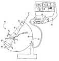
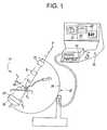
- FIG. 1illustrates a fluoroscopic image and tool navigation system in accordance with one embodiment of the present invention
- FIG. 1Aillustrates camera imaging of a tissue region with the system of FIG. 1 ;
- FIG. 2illustrate representative navigation images of one embodiment of the system of FIG. 1 ;
- FIG. 2Aillustrates the display of fluoroscope orientation in a preferred implementation of the system of FIG. 1 ;
- FIG. 3shows details of one camera calibration sub-assembly useful in the embodiment of FIG. 1 ;
- FIG. 3Ashows another calibration sub-assembly of the invention
- FIG. 4is a flow chart showing image processing and tool tracking in accordance with a first aspect of the invention
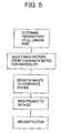
- FIG. 5illustrates operation of a second aspect of the invention
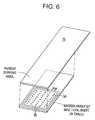
- FIG. 6illustrates a sheet fixture for use with the invention and having combined calibration and tracking elements
- FIG. 7illustrates camera calibrations corresponding to the fluoroscope poses illustrated in FIG. 1 A and used for the operation illustrated in FIG. 5 ;
- FIG. 8illustrates operation of the system to register preoperative images to a patient.
- FIG. 1illustrates elements of a basic embodiment of a system 10 in accordance with the present invention for use in an operating room environment.
- the system 10includes a fluoroscope 20 , a work station 30 having one or more displays 32 and a keyboard/mouse or other user interface 34 , and a plurality of tracking elements T 1 , T 2 , T 3 .
- the fluoroscope 20is illustrated as a C-arm fluoroscope in which an x-ray source 22 is mounted on a structural member or C-arm 26 opposite to an x-ray receiving and detecting unit, referred to herein as an imaging assembly 24 .
- the C-armmoves about a patient for producing two dimensional projection images of the patient from different angles.
- the patientremains positioned between the source and the camera, and may, for example, be situated on a table or other support, although the patient may move.
- the tracking elementsare mounted such that one element T 1 is affixed to, incorporated in or otherwise secured against movement with respect to a surgical tool or probe 40 .
- a second tracking unit T 2is fixed on or in relation to the fluoroscope 20
- a third tracking unit T 3fixed on or in relation to the patient.
- the surgical toolmay be a rigid probe as shown in FIG. 1 , allowing the tracker T 1 to be fixed at any known or convenient position, such as on its handle, or the tool may be a flexible tool, such as a catheter, flexible endoscope or an articulated tool.
- the tracker T 1is preferably a small, localized element positioned in or at the operative tip of the tool as shown by catheter tracker T 1 ′ in FIG. 1 , to track coordinates of the tip within the body of the patient.
- fluoroscopestypically operate with an x-ray source 22 positioned opposite the camera or image sensing assembly 24 . While in some systems, the X-ray source is fixed overhead, and the camera is located below a patient support, the discussion below will be illustrated with regard to the more complex case of a typical C-arm fluoroscope, in which the source and camera are connected by a structural member, the C-arm, that allows movement of the source and camera assembly about the patient so it may be positioned to produce x-ray views from different angles or perspectives.
- the imaging beamgenerally diverges at an angle
- the relative locations and orientations of the source and cameravary with position due to structural flexing and mechanical looseness
- the position of both the source and the camera with respect to the patient and/or a tool which it is desired to trackmay also vary in different shots.
- the imaging beam illustrated by B in FIG. 1diverges from the source 22 in a generally truncated conical beam shape, and the C-arm 26 is movable along a generally arcuate path to position the source and camera for imaging from different directions. This generally involves positioning the camera assembly 24 as close as possible behind the relevant tissue or operating area of the patient, while the C-arm assembly is moved roughly about a targeted imaging center to the desired viewing angle.
- the C-arm or other beam structure 26may be a somewhat flexible structure, subject to bending, deflection or sagging as the source and camera move to different positions around the patient, and the C-arm may also have other forms of dimensional variation or looseness, such as drive gear backlash, compressible elastomeric suspension components or the like, which may contribute to variations and non-repeatability of the relative disposition and alignment of the source and camera with respect to each other, and with respect to the patient, as the assembly is moved to different positions.
- the C-armmay also move eccentrically or translationally to allow better clearance of the patient support table.
- the bending deflections of the C-arm assemblymay vary the actual position of the source 22 by almost a centimeter or more with respect to the image detector, and displace it from a nominal position which may be indicated, for example, by an encoder present in the fluoroscope stand or C-arm positioning assembly. These variations may therefore be significant.
- FIG. 1Aillustrates the fluoroscope 20 in two different imaging positions, with a first position shown in solid line, and a second position in dashed line phantom.
- a tissue volume Vis imaged with a divergent beam from the above right, and a virtual beam origin or focal point at F, while the image from the second position catches a largely overlapping but partly distinct tissue volume with a divergent beam from the upper left, and a different focal point F′.
- the distances from points F, F′ to the cameramay be different, and the camera itself may shift and tilt with respect to the beam and its center axis, respectively.
- the x-ray beamis generally aimed by its center ray, whose intersection with the imaging plane, referred to as the piercing point, may be visually estimated by aiming the assembly with a laser pointing beam affixed to the source.
- the x-ray beammay be considered to have a virtual origin or focal point F at the apex of the cone beam.
- the camera assembly 24is positioned close to the patient, but is subject to constraints posed by the operating table, the nature of the surgical approach, and the necessary tools, staging, clamps and the like, so that imaging of a tissue volume somewhat off the beam center line, and at different distances along the beam, may occur.
- flexing of the C-armalso changes the distance to the focal point F and this also may slightly vary the angular disposition of the beam to the camera, so this shifting geometry may affect the fluoroscope images.
- the camera 24may utilize an image sensing unit that itself introduces further distortions into the received distribution of image radiation.
- the unitmay involve a detector that employs a phosphor surface of generally curved contour to convert the x-ray image intensity distribution to a free electron distribution.
- a curved phosphor screenis generally placed over an electron multiplier or image intensifier assembly that provides an enhanced output video signal, but may further introduce a form of electron optical distortion that depends upon the intensifier geometry and varies with the orientation of the camera assembly in the earth's magnetic field.
- Other configurations of image detectorsare also known or proposed, such as digital x-ray detectors or flat semiconductor arrays, which may have different imaging-end fidelity characteristics.
- deflection or physical movement of the camera itself as well as electron/optical distortion from the camera geometry, image detector and variations due to gravitational, magnetic or electromagnetic fieldscan all enter the image reception and affect the projective geometry and other distortion of the final image produced by the assembly.
- the equipment and procedurehas two components, a first component provided by a tracking assembly which determines position of a fluoroscope calibration fixture relative to one or both of the tool and patient body, and a second component provided by a processor operating on each image that characterizes or models the geometry of the camera and performs all subsequent processing.
- a calibration fixturethat contains an array of markers, which is either tracked as a rigid unit or affixed to the camera, while the imaged position of the markers in each fluoroscope shot serves to characterize the imaging geometry so as to allow correction of imaged features at measured distances from the camera, and permit registration of successive images in different poses.
- the surgical instrument display 40 ′ of FIGS. 1 and 2is effected by determining tool position, focus and imaging axis, and rendering the instrument in conjunction with one or more of the three types of images mentioned above.
- the processordetermines an image distortion inverse transform and projects a distorted or transformed tool graphic or image on the fluoroscopic view.
- the processordetermines the camera geometry for each image and transforms the set of fluoroscopic images such that the screen coordinates of display 33 are similar or aligned with the operating coordinates as measured by tracking elements T 2 , T 3 . This calibration results in more accurate tool tracking and representation over time. As further discussed in regard to FIG.
- the image data of an imaging sequence for a region of tissue about a common originmay be back-projected or otherwise processed to define a three dimensional stack of fluoro-CT images.
- the inventionthus allows a relatively inexpensive C-arm fluoroscope to achieve accuracy and registration to prepare CT images for tool guidance and reconstruction of arbitrary planes in the imaged volume.
- the data processing and work station unit 30 illustrated in FIG. 1may be laid out in a conventional fashion, with a display section in which, for example, a previously acquired CT or diagnostic image is displayed on one screen 32 while one or more intraoperative images 33 , such as a A/P and a lateral fluoroscopic view, are displayed on another screen.
- FIG. 2schematically represents one such display.
- the systemmay present an appearance common to many systems of the prior art, but, in a first aspect provides enhanced or corrected navigation guiding images, while in a second aspect may provide CT or other reconstructed images in display 32 formed directly from the fluoroscopic views.
- the systemmay provide dynamic referencing between these reconstructed images and a set of preoperative 3D image data.
- one fluoroscope image in display 33may be taken with the beam disposed vertically to produce an A/P fluoroscopic image projected against a horizontal plane, while another may be taken with beam projected horizontally to take a lateral view projected in a vertical plane.
- the imagetypically shows a plurality of differently shaded features, so that a patient's vertebra, for example, may appear as an irregular three-dimensional darkened region shadow-profiled in each of the views.
- the tool representation for a navigation systemmay consist of a brightly-colored dot representing tip position and a line or vector showing orientation of the body of the tool approaching its tip. In the example shown in FIG.
- the probe projected image 40 ′may extend directly over the imaged structure from the side in the A/P or top view, while when viewed in the vertical plane the perspective clearly reveals that the tip has not reached that feature but lies situated above it in space.
- the displayemploys position data from the tracking assembly to display the fluoroscope's current angle of offset from the baseline AP and lateral views.
- this displayis further enhanced by employing position data from the tracking assembly to display the fluoroscope's current angle of offset from the baseline AP and lateral fluoroscope views. This may be done as shown in FIG. 2A , by marking the fluoroscope's tracked angle or viewing axis with a marker on a circle between the twelve o'clock and three o'clock positions representing the AP and lateral view orientations.
- a tracking systemtracks the surgical instrument 40 , and the system projects a representation 40 ′ of the tool on each of the images detected by the image detector 24 .
- This representationwhile appearing as a simple vector drawing of the tool, is displayed with its position and orientation determined in the processor by applying a projective transform and an inverting image distortion transformation to the actual tool coordinates determined by the tracking elements. Thus, it is displayed in “fluoroscope image space”, rather than displaying a simple tool glyph, or correcting the image to fit the operating room coordinates of the tool.
- FIG. 3illustrates one embodiment 50 of a suitable marker array, calibration fixture or standard ST for the practice of the invention.
- the fixturemay include several sheets 52 of radiolucent material, each holding an array of radiopaque point-like markers 54 , such as stainless steel balls. (hereafter simply referred to as BBs).
- the BBsmay be of different sizes in the different planes, or may be of the same size.
- the illustrated calibration fixture 50includes a releaseable clamp assembly 51 , with a camming clamp handle 51 a , configured to attach directly on or over the face of the camera assembly.
- a tracking elementis associated with each of the tool, the patient and the fluoroscope.
- Each tracking elementis secured against movement with respect to the structure it is tracking, but advantageously, all three of those structures are free to move.
- the fluoroscopemay move freely about the patient, and both the patient and the tool may move within the operative field.
- the tracking element associated with the fluoroscopeis positioned on a calibration fixture 50 which is itself rigidly affixed to the camera of the fluoroscope as described above.
- the calibration fixturemay be removably attached in a precise position, and the tracking element T 2 may be held in a rigid oriented body affixed to the fixture 50 .
- the tracking element T 2( FIG.
- the illustrated marker platesmay each be manufactured by NC drilling of an array of holes in an acrylic, e.g., Lexan, and/or other polymer plate, with the BBs pressed into the holes, so that all marker coordinates are exactly known.
- marker platesmay be manufactured by circuit board microlithography techniques, to provide desired patterns of radiopaque markers, for example as metallization patterns, on one or more thin radiolucent films or sheets.
- the calibration assemblyrather than employing separate sheets bearing the markers, may be fabricated as a single block 50 of a suitable radiolucent material, such as a structural foam polymer having a low density and high stiffness and strength. In that case, as shown in FIG.
- holesmay be drilled to different depths and BB markers may be pressed in to defined depths Z 1 , Z 2 . . . at specific locations to create the desired space array of markers in a solid foam calibration block.
- One suitable material of this typeis a structural foam of the type used in aircraft wings for lightweight structural rigidity. This material may also be employed in separate thin marker-holding sheets. In any case the selected polymer or foam, and the number and size of the markers, are configured to remain directly in the imaging beam of the fluoroscope device and be imaged in each shot, while the position of the fixture is tracked.
- the fixture materialsare selected to avoid introducing any significant level of x-ray absorption or x-ray scattering by the plates, sheets or block, and the size and number of markers are similarly chosen to avoid excessive shadowing of the overall image, while maintaining a sufficiently dense image level for their detectability, so that both the imaging source radiation level and the resulting image density scale remain comparable to currently desired operating levels.
- the BBsare arranged in a pattern at one or more levels, with a different pattern at each level. Further, when more than one array at different depths is used, the patterns are positioned so that as the source/camera alignment changes, BBs of one pattern cast shadows substantially distinct from those of the other pattern(s).
- the array of markersis imaged in each fluoroscope shot.
- the image display system of the present inventionoperates by first identifying markers in the image. This is done in an automated procedure, for example, by a pipeline of grey level thresholding based on the x-ray absorption properties of the markers, followed by spatial clustering based on the shape and size of the markers.
- each sheethas markers arranged in a particular pattern. The pattern of each sheet will be enlarged in the image by a scale that varies with the cone divergence and the distance of the marker sheet along the axis from the optical center (or x-ray source) to the detection surface.
- the marker imageswill also be shifted radially away from the beam center axis due to the beam divergence.
- the calibration fixtureis positioned close to the image detection surface, and the markers lie in arrays distributed in planes placed substantially perpendicular to the optical axis and offset from the detection surface. In general, not all markers will be located in the image due to shadowing of some of markers, or occlusion of the marker by another object of similar x-ray absorption response.
- the candidate markers in the imageare first identified using image processing and then matched with corresponding markers in the fixture.
- One suitable protocoltakes a candidate marker P i in image coordinates, assumes it is, e.g., marker number Q j of sheet one, and then determines how many other candidate markers support this match, i.e., line up with the expected projections of the remaining markers of one array, e.g., in the pattern of sheet one.
- the number of candidates matching the known template or pattern of sheet oneis totaled, and is taken as the score of that marker.
- This processis repeated to score each candidate marker in the image, and an identification scored above a threshold is taken as correct when it leads to the highest score for that candidate, and does not conflict with the identification of another high-scoring candidate.
- Scoring of the matchis done by using the observation that the ratio of distances and angles between line segments on the same plane are invariant under perspective projection.
- the processormay proceed on a point-by-point basis, that is, an exhaustive matching process may be used to determine the correspondence between points.
- the marker detection processorpreferably employs an optimization algorithm such as the Powell, Fletcher or a simplex algorithm.
- an optimization algorithmsuch as the Powell, Fletcher or a simplex algorithm.
- One particularly useful pattern matching algorithmis that published by Chang et al in Pattern Recognition, Volume 30, No. 2, pp. 311-320, 1997. That algorithm is both fast and robust with respect to typically encountered fluoroscopic distortions.
- the Chang alignment/identification algorithmmay be accelerated relying upon the fact that the marker fixture itself has a known marker geometry.
- the marker identification modulemay predict the expected positions in the image, and search for matches within a defined small neighborhood.
- the image processor calibration moduleincludes a pre-compiled table, for example, stored in non-volatile memory, indicating the coordinates of each marker of the pattern, and preferably includes tables of separation for each pair, and/or included angle for each triplet of markers, to implement fast identification.
- each such unitmay be tracked by a separate tracking element.
- the array of marker positionsare determined in each fluoroscopic image frame from the tracking element T 2 and from the fixed relative position coordinates stored in the marker table.
- the camerais next calibrated using the marker identification information of the previous steps.
- the imaging carried out by the fluoroscopeis modeled as a camera system in which the optical center is located at the x-ray source and the imaging plane is located a distance F (focal length) away from it inside the camera assembly.
- the optical axisis the line through the x-ray source and perpendicular to the horizontal face of the camera. The intersection of the optical axis and the image plane is defined as the piercing point.
- Certain imaging or distortion characteristicsmay also be measured by the array of marker images, which thus determines a corrective perspective transformation.
- a suitable algorithmis that described by Roger Tsai in his article on 3-D camera calibration published in the IEEE Journal of Robotics and Automation , Volume RA-3, No. 4, August 1987, pp. 323-344.
- This modeldetermines radial distortion in addition to parameters using an algorithm that takes as input the matched marker and image locations, estimates of focal length and information about the number of rows and columns in the projection image.
- This algorithmis readily implemented with one or more planes of markers in the fixture 50 or 50 ′. When the fluoroscope is sufficiently rigid that focus does not vary, a single plane of markers may be used to define the camera parameters.
- a pattern of markersmay comprise a rectangular lattice, e.g., one marker every centimeter or half-centimeter in two orthogonal directions, or may occupy a non-periodic but known set of closely-spaced positions.
- the calibration fixturemay be constructed such that markers fill a peripheral band around the imaged tissue, to provide marker shadow images that lie outside the imaged area and do not obscure the tissue which is being imaged for display.
- the markersare located in the imaged field, so that the imaging camera and distortion transforms they define closely fit and characterize the geometric imaging occurring in that area.
- the image processorremoves the marker shadow-images from the fluoroscope image frame before display on the console 30 (FIG. 1 ), and may interpolate or otherwise correct image values in the surrounding image.
- the processorin one basic embodiment then integrates tracked tool position with the fluoroscope shot. That is, having tracked the position of tool 40 via tracking element T 1 , relative to the marker array 50 and tracking element T 2 , and having modeled the camera focus, optical axis and image plane relative to the position of the fixture 50 , the system then synthesizes a projection image of the tool as it dynamically tracks movement of the tool, and displays that tool navigation image on the fluoro A/P and/or lateral view of screen 33 (FIG. 1 ).
- the processorobtains the position of the front and back tips of the tool. These are fixed offsets from the coordinates of the tracking element T 1 associated with the tool.
- the trackermay also determine tool orientation relative to the patient from position and orientation relative to the tracking element T 3 on the patient at the time of image capture. Tracked position coordinates are converted to be relative to the fixed tracking element on the camera, or so that all coordinates reference the image to which the camera model applies.
- the camera calibration matrixis then applied to the front and back tip position coordinates of the tool to convert them to fluoroscope image space coordinates.
- end point coordinatesare converted to undistorted two-dimensional image coordinates (e.g., perspective coordinates) using the calculated focal length of the camera, which are then converted to distorted two-dimensional image coordinates using the lens distortion factor derived from the matrix of marker positions.
- Corresponding pixel locations in the two-dimensional fluoroscope imageare determined using the x-scale factor, the calculated origin of the image plane and scaling based on the number of pixels per millimeter in the camera image sensor and display.
- the determined positionis then integrated with the video display on the fluoroscope to show a graphical representation of the tool with its front tip location in image coordinates.
- the toolis displayed as an instrument vector, a two-dimensional line on the fluoroscopic image with a red dot representing its tip.
- the tracking assemblymay track tool movement relative to the patient, and a processor controls the tracking and determines from the position of the tool when it is necessary to redraw the integrated display using the above-described image distortion transformations to correctly situate the displayed tool in a position on a new image.
- the process of camera calibrationis a process of applying actual coordinates as determined by the tracking system and marker positions, and image coordinates as seen in the fluoroscopic marker images, to model a camera for the image.
- applicant's provision of an array of marker points having known coordinates in each of several planes, together with tracking coordinates corresponding to the absolute position of those planes and modeling of the camera image plane with respect to these tracked positionsobviates the need for lengthy initialization or correlation steps, and allows an image processor to simply identify the marker images and their positions in the image, model the camera to define focus, image plane and piercing point, and to effect image corrections with a few automated tracking measurements and transformations.
- the fixtureis preferably fixed close to the front surface of the image detector assembly, so the calibration fits the detected image closely.
- the marker positionsallow a simple computation of effective parameters to fully characterize the camera. This allows one to scale and correct positions of the image (for example a tool) when their coordinates are tracked or otherwise unknown.
- the fluoroscopeis operated to take a large number of fluoro images, with fixture tracking and camera modeling as described above, and a 3D CT image data set is reconstructed from the acquired data.
- this data setcan be acquired such that it is dimensionally accurate and useful for close surgical guidance, although parameters such as x-ray absorbance, corresponding, for example to bone or tissue density, will be of lesser accuracy than those obtainable from a CT scanner, and should not be relied upon.
- the fluoroscopic CT images so formedmay be further correlated with preoperative MRI, PET or CT images to define a direct image coordinate transformation, using established techniques such as MI (mutual information) registration, edge or contour matching, or the like, between the fluoroscopic 3D data set of the present invention and the existing preoperative 3D image set.
- MIresidual information
- Operation for forming a volume image data set for CT reconstructionproceeds as follows.
- the fluoroscopeis operated to obtain a dense set of fluoroscope images, for example, by rotating the fluoroscope approximately in a plane about the patient through 180° plus the angle of divergence of the cone beam, taking a shot every degree or less, so as to image a particular three-dimensional tissue volume of the patient in a large number of images.
- pose informationgiven for example by the position and orientation measurement of the tracking element T 2 , is stored, and the marker detection/calibration module operates on each shot so that a correction factor and a perspective projection matrix is determined for each image, as described above, to model the camera focus, image plane and optical axis for that shot.
- a coordinate system for the tissue volume for which reconstruction is desiredis then computed, and the processor then applies filtered back projection or other reconstruction processing (such as lumigraphs or lambda-CT), with indexing provided by the relative disposition of each pose, to reconstruct a three-dimensional volume data image set in the intra-operative coordinate system for a region of tissue around the origin of the reconstruction coordinate system.
- This 3-D image data set referenced to tracker coordinatesreadily allows CT reconstruction of desired planes within the image set, referenced to patient or tool position.
- the tracking systemIn order to integrate the tracking system with the fluoroscopic images, it is necessary to establish a coordinate system for the three-dimensional reconstructed volume. This entails defining the origin and the coordinate axes for that volume. Once such a coordinate system is defined in relation to all fluoro images, one can compute the back projection at voxels in a region referenced to the origin, in planes that are perpendicular to one of the coordinate axes. In the case of a spinal scan, for example, the desired CT planes will be planes perpendicular to an axis that approximates the long axis of the body.
- Such a spinal data setis especially useful, since this view cannot be directly imaged by a fluoroscope, and it is a view that is critical for visually assessing alignment of pedicle screws. Applicant establishes this common coordinate system in a way that minimizes risk of: (a) backprojecting voxels where insufficient data exists in the projections or (b) being unable to define the relationship between the natural coordinate system of the patient and that of the reconstruction.
- the camera tracking datamay be used to fit a center. This is considered an advance over systems that require a coordinate system to be specified manually.
- the tracking elementsautomatically detect coordinates of the marker array, tool and patient at the time each image is taken. Detection of the calibration fixture position allows camera modeling to provide the position of the optical center (F), optical axis and image plane, in tracker coordinates for each shot as described above.
- the combination of tracked position and modeled camera informationis used to define a coordinate system for the reconstruction, which is preferably computed by performing statistical and computational geometry analysis on the pose information recorded and derived for each of the fluoroscopic image frames.
- the “projection plane”is the plane on which the image is formed through the operation of perspective projection.
- the “optical center” or the “center of projection”, Cis located at a distance F, the focal length of the optical system, from the projection plane. In the case of a fluoroscope, this is the actual location of the x-ray source; the source is positioned at the optical center of the imaging system.
- the projection of a given point M in the worldis computed as the intersection of the ray connecting M and the optical center C with the projection plane.
- the “optical axis” of a fluoroscopic imaging systemis the line that passes through its optical center (the x-ray source) and is normal to the projection plane.
- the point at which the optical axis intersects the projection planeis known as the “principal point” or the “piercing point”.
- a textbooksuch as “Three-Dimensional Computer Vision” by Olivier Faugeras, MIT Press, may be consulted for further background or illustration of basic concepts used here.
- Applicant's approach to the problem of computing a coordinate origin for reconstructionassures that in this set of data, the origin of the 3D coordinate system lies at a point that is the center of the region that the surgeon is most interested in visualizing. That point is identified in a prototype system by computing a point that is closest to being centered in all of the acquired fluoroscopic images, and then taking that point as the origin of a coordinate system in which the reconstruction is performed.
- FIG. 5sets forth the steps of this processing.
- Each configuration of the C-armdefines a coordinate system in which the origin, (0,0,0) is defined by the location of the x-ray source. The principal point is located at (0,0,F) where F is the focal length. That is, the optical axis, or axis of the imaging beam, is aligned along the third axis.
- Fthe focal length
- FIG. 7Such a situation is schematically illustrated in FIG. 7 for the two fluoroscope positions shown in FIG. 1 A. If all the fluoroscope configurations are taken in the context of a common world-coordinate system, each of these configurations defines a unique optical axis.
- the point in three-space where all these optical axes intersectwould be visible and centered in all the projection images.
- applicantdefines a projection center of the imaged tissue volume from the ensemble of camera models, and uses this intersection point as the origin for a three-dimensional reconstruction. This is done by applying a coordinate determination module, which identifies the optical axis intersection point as the intersection of, or best fit to, the N 2 pairs of optical axes of the modeled cameras for the N poses.
- the processorincorporates a software condition check for skewness of lines. If the optical axes are skew, the processor defines the intersection point as a computed point that is halfway between the two lines. In order to address the situation (b), the processor takes the mean coordinates of the N 2 skew-intersection points determined in the first step as its common center of projection. Thus the cluster of points defined by the N 2 pairs of axes determines a single point. This point is defined as the origin of the tissue region for which reconstruction is undertaken.
- the axial planes of the reconstructionare to be parallel to the plane of motion of the x-ray source.
- Applicant's presently preferred processing modulecomputes the plane of motion of the x-ray source by fitting a least-squares solution to the poses of the x-ray source. Any two non-collinear vectors in this plane define a basis for this plane and serve as two of the axes for the coordinate system. The module also computes a normal to this plane to serve as the third coordinate axis.
- the coordinate axis computationmay be done by using eigen-analysis of the covariance matrix of the coordinates of the optical centers (x-ray source locations) and the principal points in the world-coordinate system. These eigenvectors are then ordered in order of decreasing eigenvalue. The first two eigenvectors provide a basis for the axial plane of interest, and the third eigenvector provides the normal to this plane. This procedure thus provides all three coordinate axes for the three-dimensional reconstruction. This determination is fully automated, and requires only the tracker data and camera models determined by the processor when each shot is taken. Further background and details of implementation for applying the eigenanalysis technique to define coordinate axes may be found in reference texts, such as the 1984 textbook “Pattern Recognition” by J. Therrien.
- the processorfilters and back-projects the image data to form a volume image data set, from which CT planes may be reconstructed or retrieved in a conventional manner.
- the back projection stepmay utilize fast or improved processes, such as the fast Feldkamp algorithm or other variant, or may be replaced by other suitable volume data reconstruction technique, such as the local or Lambda tomography method described by A. Louis and P. Maass in IEEE Transac. Med. Imag. 764-769, (1993) and papers cited therein.
- a simple set of automated tracking elements combined with image processing operative on a fixed or tracked marker arrayprovides accurate tool tracking fluoroscope images, or a set of geometrically accurate reconstructed or CT images from the shadowgraphic images of a C-arm or intraoperative fluoroscope.
- the nature of the multi-point marker-defined camera image modelallows the processor to quickly register, reference to a common coordinate system and back project or otherwise reconstruct accurate volume image data, and the fast determination of a camera parameter model for each shot proceeds quickly and allows accurate tool display for intraoperative tool navigation and dynamic tracking, without requiring rigid frames or robotic assemblies that can obstruct surgery, and without the necessity of matching to an MRI or PET database to achieve precision.
- the models, transformations and fitting to a coordinate systemproceed from the tracker position measurements of the marker fixture relative to the patient or tool, rather than from an extrinsic fixed frame, reducing potential sources of cumulative errors and simplifying the task of registering and transforming to common coordinates. Applicant is therefore able to precisely track and display the tool in real time, and to produce accurate fluoro-CT images using a C-arm fluoroscope.
- tracking elementseach fixed with respect to one of a few movable objects.
- these tracking elementsmay be affixed by belts, frames, supports, clips, handles or other securing or orienting structures known in the art.
- applicant's preferred tracking elementis a magnetic field tracking element, which may be oriented and affixed in a rigid housing that allows it to secure to the structure to be tracked.
- the calibration fixturehas been described above as being preferably affixed to the image detector portion of the fluoroscope, where, illustratively one or several precision arrays of markers located along the imaging axis provide necessary data in the image itself to characterize the camera each time an image is taken.
- This locationwith the markers in a single fixture, provides a high level of accuracy in determining the desired camera parameters, and enables tracking to proceed without obstructing the surgical field.
- the constraint of positioning the calibration fixture between the target tissue and the detectormay limit flexibility in positioning the image detector near the patient, this may be addressed in other embodiments by having all or a portion of the marker array assembly implemented with markers located on or in a radiographic support table ( 75 , FIG. 6 ) or other structure on which the patient or the imaged tissue portion is supported.
- the table or support itselfwhich is radiolucent, may have a thickness and structure that permits markers to be embedded at different depths.
- itmay be formed of a structural foam material as described above in regard to the marker fixture of FIG. 3 A.
- the markersmay be included in one or more sheets that fit within the x-ray sheet film tray of a conventional radiography table, or such marker sheets may be laminated to the bottom and/or top surfaces of the table.
- the tracking element T 2may then be attached anywhere on the rigid structure of the table itself, with suitable offsets stored in a fixed memory element of the system.
- the total angular range of the poses in which useful marker images will appear in the fluoroscope imagesmay be restricted to somewhat under 180°.
- the image planewill generally not be parallel to the marker arrays, so a different set of computations is utilized by the processor to characterize the camera position and geometry. However, these computations involve straightforward camera modeling, and may be accelerated by also tracking the image detector with an additional element T 2 ′.
- FIG. 6shows elements of one such embodiment wherein a marker array 50 ′′ is formed as a pattern of metallized dots 56 , which may be formed lithographically on a printed-circuit type sheet. As indicated schematically in this Figure, the sheet may also bear one or more lithographically-formed conductive loops 58 , configured as a field generating or field sensing loop, for defining one or more elements of a magnetic tracking assembly.
- Three or more such patterned loopsmay be formed to constitute a basic electromagnetic generator or sensor that advantageously is precisely pre-aligned with respect to the coordinates of the markers 56 by virtue of its having been manufactured using a pattern lithography mask.
- the magnetic circuit loopsmay define magnetic multipoles for establishing or sensing position-tracking electromagnetic fields, or may, for example, include one or more coils of a system of Helmholtz coils for establishing a gradient field in the region where tracking is to occur. These may operate in conjunction with other coils disposed elsewhere for defining the tracking field,
- the implementation of magnetic tracking and radiographic marker elements on a sheetalso allows plural sheets to be positioned and tracked separately for effecting the imaged based processing of the present invention.
- a fluoro-CT data setis constructed as described above, and the fluoro-3D data set is then registered or correlated to an existing MRI, CT or PET 3D data set to form a fused set of images. These are then displayed on the system console 30 ( FIG. 1 ) to provide enhanced patient information during surgery.
- the coordinates of the fluoro-CT imagesare known from the coordinates used in the reconstruction processing, while the correlation of the two different 3D image sets may proceed without reference to patient or other tracking coordinates, using any conventional 3D registration or correlation technique. This provides fast and effective fused image sets for surgical guidance or diagnostic evaluation.
- the systemneed not produce detailed fluoro-CT images, or need not display those images.
- the fluoro-CT images, or a lesser quality set of fluoro-CT images constructed from a faster (smaller) scan sequence of fluoro images, defined in tracker coordinatesmay be produced and simply registered to a preoperative 3D data set in order to bring that preoperative image data set into the tracker coordinate system.
- the systemapplies this registration, and proceeds thereafter by simply tracking the patient and the tool, and displaying the appropriate preoperative images for each tracked location as shown in FIG. 8 .
- the systemprovides an automated registration system for the intraoperative display of preoperative MRI, PET or CT images, without requiring placement or imaging of fiducials, without requiring the surgeon to initialize or set up a plurality of reference points, without requiring the surgeon to cut down to or expose a fixed skeletal registration feature, and without requiring immobilization of the patient in a frame or support.
- the intermediate fluoro-CT imagesare produced as part of an automated modeling and coordinatizing process, and both the production and the registration of these images to the preoperative data set may proceed entirely automated in software, for example, registering by mutual information (MI), feature correlation or similar process.
- MImutual information
Landscapes
- Health & Medical Sciences (AREA)
- Life Sciences & Earth Sciences (AREA)
- Engineering & Computer Science (AREA)
- Medical Informatics (AREA)
- Surgery (AREA)
- Public Health (AREA)
- Heart & Thoracic Surgery (AREA)
- Veterinary Medicine (AREA)
- Nuclear Medicine, Radiotherapy & Molecular Imaging (AREA)
- General Health & Medical Sciences (AREA)
- Animal Behavior & Ethology (AREA)
- Molecular Biology (AREA)
- Biomedical Technology (AREA)
- Pathology (AREA)
- Radiology & Medical Imaging (AREA)
- Physics & Mathematics (AREA)
- High Energy & Nuclear Physics (AREA)
- Optics & Photonics (AREA)
- Biophysics (AREA)
- Computer Vision & Pattern Recognition (AREA)
- Robotics (AREA)
- Human Computer Interaction (AREA)
- Oral & Maxillofacial Surgery (AREA)
- Apparatus For Radiation Diagnosis (AREA)
Abstract
Description
Claims (19)
Priority Applications (1)
| Application Number | Priority Date | Filing Date | Title |
|---|---|---|---|
| US10/308,340US6856827B2 (en) | 2000-04-28 | 2002-12-02 | Fluoroscopic tracking and visualization system |
Applications Claiming Priority (2)
| Application Number | Priority Date | Filing Date | Title |
|---|---|---|---|
| US09/560,608US6490475B1 (en) | 2000-04-28 | 2000-04-28 | Fluoroscopic tracking and visualization system |
| US10/308,340US6856827B2 (en) | 2000-04-28 | 2002-12-02 | Fluoroscopic tracking and visualization system |
Related Parent Applications (1)
| Application Number | Title | Priority Date | Filing Date |
|---|---|---|---|
| US09/560,608ContinuationUS6490475B1 (en) | 2000-04-28 | 2000-04-28 | Fluoroscopic tracking and visualization system |
Publications (2)
| Publication Number | Publication Date |
|---|---|
| US20030088179A1 US20030088179A1 (en) | 2003-05-08 |
| US6856827B2true US6856827B2 (en) | 2005-02-15 |
Family
ID=24238527
Family Applications (1)
| Application Number | Title | Priority Date | Filing Date |
|---|---|---|---|
| US10/308,340Expired - LifetimeUS6856827B2 (en) | 2000-04-28 | 2002-12-02 | Fluoroscopic tracking and visualization system |
Country Status (1)
| Country | Link |
|---|---|
| US (1) | US6856827B2 (en) |
Cited By (267)
| Publication number | Priority date | Publication date | Assignee | Title |
|---|---|---|---|---|
| US20030123720A1 (en)* | 2001-11-30 | 2003-07-03 | Laurent Launay | Method and apparatus for reconstructing an image of an object |
| US20040064022A1 (en)* | 2002-09-27 | 2004-04-01 | Infraredx, Inc. | Spectroscopic catheter system with widely tunable source and method of operation |
| US20050004443A1 (en)* | 2003-07-01 | 2005-01-06 | General Electric Compnay | Cardiac imaging system and method for planning minimally invasive direct coronary artery bypass surgery |
| US20050038337A1 (en)* | 2003-08-11 | 2005-02-17 | Edwards Jerome R. | Methods, apparatuses, and systems useful in conducting image guided interventions |
| US20050065433A1 (en)* | 2003-09-24 | 2005-03-24 | Anderson Peter Traneus | System and method for software configurable electromagnetic tracking |
| US20050143777A1 (en)* | 2003-12-19 | 2005-06-30 | Sra Jasbir S. | Method and system of treatment of heart failure using 4D imaging |
| US20050163279A1 (en)* | 2003-12-19 | 2005-07-28 | Matthias Mitschke | Method and apparatus for image support of an operative procedure implemented with a medical instrument |
| US20050192575A1 (en)* | 2004-02-20 | 2005-09-01 | Pacheco Hector O. | Method of improving pedicle screw placement in spinal surgery |
| US20050267353A1 (en)* | 2004-02-04 | 2005-12-01 | Joel Marquart | Computer-assisted knee replacement apparatus and method |
| US20060009755A1 (en)* | 2003-09-04 | 2006-01-12 | Sra Jasbir S | Method and system for ablation of atrial fibrillation and other cardiac arrhythmias |
| US20060121849A1 (en)* | 2003-07-01 | 2006-06-08 | Peter Traneus Anderson | Electromagnetic coil array integrated into flat-panel detector |
| US20060173293A1 (en)* | 2003-02-04 | 2006-08-03 | Joel Marquart | Method and apparatus for computer assistance with intramedullary nail procedure |
| US20060258938A1 (en)* | 2005-05-16 | 2006-11-16 | Intuitive Surgical Inc. | Methods and system for performing 3-D tool tracking by fusion of sensor and/or camera derived data during minimally invasive robotic surgery |
| US20070003016A1 (en)* | 2005-06-30 | 2007-01-04 | Thomas Brunner | Method for contour visualization of regions of interest in 2D fluoroscopy images |
| US20070016009A1 (en)* | 2005-06-27 | 2007-01-18 | Lakin Ryan C | Image guided tracking array and method |
| US20070016008A1 (en)* | 2005-06-23 | 2007-01-18 | Ryan Schoenefeld | Selective gesturing input to a surgical navigation system |
| US20070038223A1 (en)* | 2003-02-04 | 2007-02-15 | Joel Marquart | Computer-assisted knee replacement apparatus and method |
| US20070060799A1 (en)* | 2005-09-13 | 2007-03-15 | Lyon Torsten M | Apparatus and method for automatic image guided accuracy verification |
| US20070073306A1 (en)* | 2004-03-08 | 2007-03-29 | Ryan Lakin | Cutting block for surgical navigation |
| US20070073137A1 (en)* | 2005-09-15 | 2007-03-29 | Ryan Schoenefeld | Virtual mouse for use in surgical navigation |
| US20070073133A1 (en)* | 2005-09-15 | 2007-03-29 | Schoenefeld Ryan J | Virtual mouse for use in surgical navigation |
| US20070164895A1 (en)* | 2005-11-30 | 2007-07-19 | General Electric Company | System and method for disambiguating the phase of a field received from a transmitter in an electromagnetic tracking system |
| US20070167801A1 (en)* | 2005-12-02 | 2007-07-19 | Webler William E | Methods and apparatuses for image guided medical procedures |
| US20080118116A1 (en)* | 2006-11-20 | 2008-05-22 | General Electric Company | Systems and methods for tracking a surgical instrument and for conveying tracking information via a network |
| US20080119728A1 (en)* | 2006-10-05 | 2008-05-22 | Visionsense Ltd. | Method and system for superimposing three dimensional medical information on a three dimensional image |
| US20080132757A1 (en)* | 2006-12-01 | 2008-06-05 | General Electric Company | System and Method for Performing Minimally Invasive Surgery Using a Multi-Channel Catheter |
| US20080139929A1 (en)* | 2006-12-06 | 2008-06-12 | General Electric Company | System and method for tracking an invasive surgical instrument while imaging a patient |
| US20080137924A1 (en)* | 2006-09-29 | 2008-06-12 | Jan Boese | Device for merging a 2D radioscopy image with an image from a 3D image data record |
| US20080144906A1 (en)* | 2006-10-09 | 2008-06-19 | General Electric Company | System and method for video capture for fluoroscopy and navigation |
| US20080228065A1 (en)* | 2007-03-13 | 2008-09-18 | Viswanathan Raju R | System and Method for Registration of Localization and Imaging Systems for Navigational Control of Medical Devices |
| US20080281334A1 (en)* | 2006-08-15 | 2008-11-13 | Ao Technology Ag | Method and Device for Computer Assisted Distal Locking of Intramedullary Nails |
| US20080292046A1 (en)* | 2007-05-09 | 2008-11-27 | Estelle Camus | Bronchopulmonary medical services system and imaging method |
| US20080300478A1 (en)* | 2007-05-30 | 2008-12-04 | General Electric Company | System and method for displaying real-time state of imaged anatomy during a surgical procedure |
| US20080319491A1 (en)* | 2007-06-19 | 2008-12-25 | Ryan Schoenefeld | Patient-matched surgical component and methods of use |
| US7471202B2 (en) | 2006-03-29 | 2008-12-30 | General Electric Co. | Conformal coil array for a medical tracking system |
| US20090086900A1 (en)* | 2007-09-28 | 2009-04-02 | Searete Llc, A Limited Liability Corporation Of The State Of Delaware | Portable aspects for x-ray fluorescence visualizer, imager, or information provider |
| US20090086905A1 (en)* | 2007-09-28 | 2009-04-02 | Searete Llc, A Limited Liability Corporation Of The State Of Delaware | X-ray fluorescence visualizer, imager, or information provider |
| US20090084951A1 (en)* | 2007-09-28 | 2009-04-02 | Searete Llc, A Limited Liability Corporation Of The State Of Delaware | Scintillator aspects for X-Ray fluorescence visualizer, imager, or information provider |
| US20090086894A1 (en)* | 2007-09-28 | 2009-04-02 | Searete Llc, A Limited Liability Corporation Of The State Of Delaware | Time of flight aspects for X-Ray fluorescence visualizer, imager, or information provider |
| US20090086895A1 (en)* | 2007-09-28 | 2009-04-02 | Searete Llc. A Limited Liability Corporation Of The State Of Delaware | Geometric X-Ray fluorescence visualizer, imager, or information provider |
| US20090086903A1 (en)* | 2007-09-28 | 2009-04-02 | Searete LLC, a limited liability corporation of | Selective elemental color providing for X-ray fluorescence visualization, imaging, or information providing |
| US20090086899A1 (en)* | 2007-09-28 | 2009-04-02 | Searete Llc, A Limited Liability Corporation Of The State Of Delaware | Repositioning X-ray fluorescence visualizer, imager, or information provider |
| US20090086902A1 (en)* | 2007-09-28 | 2009-04-02 | Searete Llc, A Limited Liability Corporation Of The State Of Delaware | Personal transportable X-ray fluorescence visualizing, imaging, or information providing |
| US20090086893A1 (en)* | 2007-09-28 | 2009-04-02 | Searete Llc, A Limited Liability Corporation Of The State Of Delaware | Combining X-Ray fluorescence visualizer, imager, or information provider |
| US20090086904A1 (en)* | 2007-09-28 | 2009-04-02 | Searete Llc, A Limited Liability Corporation Of The State Of Delaware | X-Ray fluorescence visualizing, imaging, or information providing of chemicals, compounds, or biological materials |
| US20090086892A1 (en)* | 2007-09-28 | 2009-04-02 | Searete Llc, A Limited Liability Corporation Of The State Of Delaware | Proximity-based X-ray fluorescence visualizer, imager, or information provider |
| US20090086896A1 (en)* | 2007-09-28 | 2009-04-02 | Searete Llc, A Limited Liability Corporation Of The State Of Delaware | Tool based X-ray fluorescence visualizing, imaging, or information providing |
| US20090096443A1 (en)* | 2007-10-11 | 2009-04-16 | General Electric Company | Coil arrangement for an electromagnetic tracking system |
| US7532997B2 (en) | 2006-04-17 | 2009-05-12 | General Electric Company | Electromagnetic tracking using a discretized numerical field model |
| US20090135992A1 (en)* | 2007-11-27 | 2009-05-28 | Regis Vaillant | Method for the processing of radiography cardiac images with a view to obtaining a subtracted and registered image |
| WO2009085806A1 (en)* | 2007-12-31 | 2009-07-09 | St. Jude Medical, Atrial Fibrillation Division, Inc. | Reduced radiation fluoroscopic system |
| US20090183740A1 (en)* | 2008-01-21 | 2009-07-23 | Garrett Sheffer | Patella tracking method and apparatus for use in surgical navigation |
| US20090205403A1 (en)* | 2008-02-15 | 2009-08-20 | Siemens Aktiengesellschaft | Calibration of an instrument location facility with an imaging apparatus |
| US20090281566A1 (en)* | 2003-08-11 | 2009-11-12 | Edwards Jerome R | Bodily sealants and methods and apparatus for image-guided delivery of same |
| US20090296893A1 (en)* | 2008-05-28 | 2009-12-03 | Norbert Strobel | Calibration of a multi-plane x-ray unit |
| US7649975B2 (en) | 2007-09-28 | 2010-01-19 | Searete Llc | X-ray fluorescence visualizing, imaging, or information providing of chemicals, compounds, or biological materials |
| US20100069741A1 (en)* | 2005-11-23 | 2010-03-18 | General Electric Company | System and method for detection of electromagnetic radiation by amorphous silicon x-ray detector for metal detection in x-ray imaging |
| US20100098316A1 (en)* | 2008-10-13 | 2010-04-22 | George Yiorgos Papaioannou | Dynamic biplane roentgen stereophotogrammetric analysis |
| US20100155607A1 (en)* | 2008-12-24 | 2010-06-24 | Fujifilm Corporation | Radiographic image capturing system, processor and radiographic image capturing method |
| US20100164950A1 (en)* | 2008-12-31 | 2010-07-01 | Intuitive Surgical, Inc. | Efficient 3-d telestration for local robotic proctoring |
| US20100318099A1 (en)* | 2009-06-16 | 2010-12-16 | Intuitive Surgical, Inc. | Virtual measurement tool for minimally invasive surgery |
| US20100331855A1 (en)* | 2005-05-16 | 2010-12-30 | Intuitive Surgical, Inc. | Efficient Vision and Kinematic Data Fusion For Robotic Surgical Instruments and Other Applications |
| US20110123084A1 (en)* | 2009-11-25 | 2011-05-26 | David Sebok | Marker identification and processing in x-ray images |
| US20110123070A1 (en)* | 2009-11-25 | 2011-05-26 | David Sebok | Method for x-ray marker localization in 3d space in the presence of motion |
| US20110123080A1 (en)* | 2009-11-25 | 2011-05-26 | David Sebok | Method for tracking x-ray markers in serial ct projection images |
| US20110123085A1 (en)* | 2009-11-25 | 2011-05-26 | David Sebok | Method for accurate sub-pixel localization of markers on x-ray images |
| US20110123088A1 (en)* | 2009-11-25 | 2011-05-26 | David Sebok | Extracting patient motion vectors from marker positions in x-ray images |
| US8165659B2 (en) | 2006-03-22 | 2012-04-24 | Garrett Sheffer | Modeling method and apparatus for use in surgical navigation |
| US20130245429A1 (en)* | 2012-02-28 | 2013-09-19 | Siemens Aktiengesellschaft | Robust multi-object tracking using sparse appearance representation and online sparse appearance dictionary update |
| US8620113B2 (en) | 2011-04-25 | 2013-12-31 | Microsoft Corporation | Laser diode modes |
| US8635637B2 (en) | 2011-12-02 | 2014-01-21 | Microsoft Corporation | User interface presenting an animated avatar performing a media reaction |
| US8638985B2 (en) | 2009-05-01 | 2014-01-28 | Microsoft Corporation | Human body pose estimation |
| US8660303B2 (en) | 2009-05-01 | 2014-02-25 | Microsoft Corporation | Detection of body and props |
| US8696549B2 (en) | 2010-08-20 | 2014-04-15 | Veran Medical Technologies, Inc. | Apparatus and method for four dimensional soft tissue navigation in endoscopic applications |
| US8760395B2 (en) | 2011-05-31 | 2014-06-24 | Microsoft Corporation | Gesture recognition techniques |
| US8781186B2 (en) | 2010-05-04 | 2014-07-15 | Pathfinder Therapeutics, Inc. | System and method for abdominal surface matching using pseudo-features |
| US8792963B2 (en) | 2007-09-30 | 2014-07-29 | Intuitive Surgical Operations, Inc. | Methods of determining tissue distances using both kinematic robotic tool position information and image-derived position information |
| US8898687B2 (en) | 2012-04-04 | 2014-11-25 | Microsoft Corporation | Controlling a media program based on a media reaction |
| US8934961B2 (en) | 2007-05-18 | 2015-01-13 | Biomet Manufacturing, Llc | Trackable diagnostic scope apparatus and methods of use |
| US8959541B2 (en) | 2012-05-04 | 2015-02-17 | Microsoft Technology Licensing, Llc | Determining a future portion of a currently presented media program |
| US9076212B2 (en) | 2006-05-19 | 2015-07-07 | The Queen's Medical Center | Motion tracking system for real time adaptive imaging and spectroscopy |
| US9078685B2 (en) | 2007-02-16 | 2015-07-14 | Globus Medical, Inc. | Method and system for performing invasive medical procedures using a surgical robot |
| US9100685B2 (en) | 2011-12-09 | 2015-08-04 | Microsoft Technology Licensing, Llc | Determining audience state or interest using passive sensor data |
| US9125611B2 (en) | 2010-12-13 | 2015-09-08 | Orthoscan, Inc. | Mobile fluoroscopic imaging system |
| US9138165B2 (en) | 2012-02-22 | 2015-09-22 | Veran Medical Technologies, Inc. | Systems, methods and devices for forming respiratory-gated point cloud for four dimensional soft tissue navigation |
| US20150375399A1 (en)* | 2014-06-27 | 2015-12-31 | Hansen Medical, Inc. | User interface for medical robotics system |
| US9305365B2 (en) | 2013-01-24 | 2016-04-05 | Kineticor, Inc. | Systems, devices, and methods for tracking moving targets |
| US9398675B2 (en) | 2009-03-20 | 2016-07-19 | Orthoscan, Inc. | Mobile imaging apparatus |
| US9492240B2 (en) | 2009-06-16 | 2016-11-15 | Intuitive Surgical Operations, Inc. | Virtual measurement tool for minimally invasive surgery |
| US20160331481A1 (en)* | 2002-03-20 | 2016-11-17 | P Tech, Llc | Methods of using a robotic spine system |
| US9606209B2 (en) | 2011-08-26 | 2017-03-28 | Kineticor, Inc. | Methods, systems, and devices for intra-scan motion correction |
| US20170119339A1 (en)* | 2012-06-21 | 2017-05-04 | Globus Medical, Inc. | Systems and methods of checking registrations for surgical systems |
| WO2017083494A1 (en) | 2015-11-13 | 2017-05-18 | Stryker European Holdings I, Llc | Adaptive positioning technology |
| US9717461B2 (en) | 2013-01-24 | 2017-08-01 | Kineticor, Inc. | Systems, devices, and methods for tracking and compensating for patient motion during a medical imaging scan |
| US9734589B2 (en) | 2014-07-23 | 2017-08-15 | Kineticor, Inc. | Systems, devices, and methods for tracking and compensating for patient motion during a medical imaging scan |
| US9782141B2 (en) | 2013-02-01 | 2017-10-10 | Kineticor, Inc. | Motion tracking system for real time adaptive motion compensation in biomedical imaging |
| US9782229B2 (en) | 2007-02-16 | 2017-10-10 | Globus Medical, Inc. | Surgical robot platform |
| US9826942B2 (en) | 2009-11-25 | 2017-11-28 | Dental Imaging Technologies Corporation | Correcting and reconstructing x-ray images using patient motion vectors extracted from marker positions in x-ray images |
| US9943247B2 (en) | 2015-07-28 | 2018-04-17 | The University Of Hawai'i | Systems, devices, and methods for detecting false movements for motion correction during a medical imaging scan |
| US9974525B2 (en) | 2014-10-31 | 2018-05-22 | Covidien Lp | Computed tomography enhanced fluoroscopic system, device, and method of utilizing the same |
| US10004462B2 (en) | 2014-03-24 | 2018-06-26 | Kineticor, Inc. | Systems, methods, and devices for removing prospective motion correction from medical imaging scans |
| US10080615B2 (en) | 2015-08-12 | 2018-09-25 | Globus Medical, Inc. | Devices and methods for temporary mounting of parts to bone |
| US20180271598A1 (en)* | 2017-03-24 | 2018-09-27 | The Spectranetics Corporation | Laser energy delivery devices including distal tip orientation indicators |
| US10117632B2 (en) | 2016-02-03 | 2018-11-06 | Globus Medical, Inc. | Portable medical imaging system with beam scanning collimator |
| US10136954B2 (en) | 2012-06-21 | 2018-11-27 | Globus Medical, Inc. | Surgical tool systems and method |
| US10143438B2 (en) | 2015-08-06 | 2018-12-04 | Xiang Zhang | System for 3D object modeling and tracking in X-ray imaging |
| US10206746B2 (en) | 2013-03-15 | 2019-02-19 | Auris Health, Inc. | User interface for active drive apparatus with finite range of motion |
| US10231791B2 (en) | 2012-06-21 | 2019-03-19 | Globus Medical, Inc. | Infrared signal based position recognition system for use with a robot-assisted surgery |
| US10292778B2 (en) | 2014-04-24 | 2019-05-21 | Globus Medical, Inc. | Surgical instrument holder for use with a robotic surgical system |
| US10327708B2 (en) | 2013-01-24 | 2019-06-25 | Kineticor, Inc. | Systems, devices, and methods for tracking and compensating for patient motion during a medical imaging scan |
| US10350013B2 (en) | 2012-06-21 | 2019-07-16 | Globus Medical, Inc. | Surgical tool systems and methods |
| US10357184B2 (en) | 2012-06-21 | 2019-07-23 | Globus Medical, Inc. | Surgical tool systems and method |
| US10357257B2 (en) | 2014-07-14 | 2019-07-23 | KB Medical SA | Anti-skid surgical instrument for use in preparing holes in bone tissue |
| US10420616B2 (en) | 2017-01-18 | 2019-09-24 | Globus Medical, Inc. | Robotic navigation of robotic surgical systems |
| US10448910B2 (en) | 2016-02-03 | 2019-10-22 | Globus Medical, Inc. | Portable medical imaging system |
| US10546423B2 (en) | 2015-02-03 | 2020-01-28 | Globus Medical, Inc. | Surgeon head-mounted display apparatuses |
| US10548620B2 (en) | 2014-01-15 | 2020-02-04 | Globus Medical, Inc. | Notched apparatus for guidance of an insertable instrument along an axis during spinal surgery |
| US10555782B2 (en) | 2015-02-18 | 2020-02-11 | Globus Medical, Inc. | Systems and methods for performing minimally invasive spinal surgery with a robotic surgical system using a percutaneous technique |
| US10573023B2 (en) | 2018-04-09 | 2020-02-25 | Globus Medical, Inc. | Predictive visualization of medical imaging scanner component movement |
| US10569794B2 (en) | 2015-10-13 | 2020-02-25 | Globus Medical, Inc. | Stabilizer wheel assembly and methods of use |
| US10617324B2 (en) | 2014-04-23 | 2020-04-14 | Veran Medical Technologies, Inc | Apparatuses and methods for endobronchial navigation to and confirmation of the location of a target tissue and percutaneous interception of the target tissue |
| US10624701B2 (en) | 2014-04-23 | 2020-04-21 | Veran Medical Technologies, Inc. | Apparatuses and methods for registering a real-time image feed from an imaging device to a steerable catheter |
| US10624710B2 (en) | 2012-06-21 | 2020-04-21 | Globus Medical, Inc. | System and method for measuring depth of instrumentation |
| US10646283B2 (en) | 2018-02-19 | 2020-05-12 | Globus Medical Inc. | Augmented reality navigation systems for use with robotic surgical systems and methods of their use |
| US10646298B2 (en) | 2015-07-31 | 2020-05-12 | Globus Medical, Inc. | Robot arm and methods of use |
| US10646280B2 (en) | 2012-06-21 | 2020-05-12 | Globus Medical, Inc. | System and method for surgical tool insertion using multiaxis force and moment feedback |
| US10653497B2 (en) | 2006-02-16 | 2020-05-19 | Globus Medical, Inc. | Surgical tool systems and methods |
| US10660712B2 (en) | 2011-04-01 | 2020-05-26 | Globus Medical Inc. | Robotic system and method for spinal and other surgeries |
| US10674982B2 (en) | 2015-08-06 | 2020-06-09 | Covidien Lp | System and method for local three dimensional volume reconstruction using a standard fluoroscope |
| US10675094B2 (en) | 2017-07-21 | 2020-06-09 | Globus Medical Inc. | Robot surgical platform |
| US10687905B2 (en) | 2015-08-31 | 2020-06-23 | KB Medical SA | Robotic surgical systems and methods |
| US10688283B2 (en) | 2013-03-13 | 2020-06-23 | Auris Health, Inc. | Integrated catheter and guide wire controller |
| US10699448B2 (en) | 2017-06-29 | 2020-06-30 | Covidien Lp | System and method for identifying, marking and navigating to a target using real time two dimensional fluoroscopic data |
| US10702226B2 (en) | 2015-08-06 | 2020-07-07 | Covidien Lp | System and method for local three dimensional volume reconstruction using a standard fluoroscope |
| US10716525B2 (en) | 2015-08-06 | 2020-07-21 | Covidien Lp | System and method for navigating to target and performing procedure on target utilizing fluoroscopic-based local three dimensional volume reconstruction |
| US10716515B2 (en) | 2015-11-23 | 2020-07-21 | Kineticor, Inc. | Systems, devices, and methods for tracking and compensating for patient motion during a medical imaging scan |
| US10758315B2 (en) | 2012-06-21 | 2020-09-01 | Globus Medical Inc. | Method and system for improving 2D-3D registration convergence |
| US10765438B2 (en) | 2014-07-14 | 2020-09-08 | KB Medical SA | Anti-skid surgical instrument for use in preparing holes in bone tissue |
| US10799298B2 (en) | 2012-06-21 | 2020-10-13 | Globus Medical Inc. | Robotic fluoroscopic navigation |
| US10806471B2 (en) | 2017-01-18 | 2020-10-20 | Globus Medical, Inc. | Universal instrument guide for robotic surgical systems, surgical instrument systems, and methods of their use |
| US10813704B2 (en) | 2013-10-04 | 2020-10-27 | Kb Medical, Sa | Apparatus and systems for precise guidance of surgical tools |
| US10828120B2 (en) | 2014-06-19 | 2020-11-10 | Kb Medical, Sa | Systems and methods for performing minimally invasive surgery |
| US10835153B2 (en) | 2017-12-08 | 2020-11-17 | Auris Health, Inc. | System and method for medical instrument navigation and targeting |
| US10842453B2 (en) | 2016-02-03 | 2020-11-24 | Globus Medical, Inc. | Portable medical imaging system |
| US10849702B2 (en) | 2013-03-15 | 2020-12-01 | Auris Health, Inc. | User input devices for controlling manipulation of guidewires and catheters |
| US10866119B2 (en) | 2016-03-14 | 2020-12-15 | Globus Medical, Inc. | Metal detector for detecting insertion of a surgical device into a hollow tube |
| US10864057B2 (en) | 2017-01-18 | 2020-12-15 | Kb Medical, Sa | Universal instrument guide for robotic surgical systems, surgical instrument systems, and methods of their use |
| US10874466B2 (en) | 2012-06-21 | 2020-12-29 | Globus Medical, Inc. | System and method for surgical tool insertion using multiaxis force and moment feedback |
| US10893843B2 (en) | 2017-10-10 | 2021-01-19 | Covidien Lp | System and method for identifying and marking a target in a fluoroscopic three-dimensional reconstruction |
| US10893912B2 (en) | 2006-02-16 | 2021-01-19 | Globus Medical Inc. | Surgical tool systems and methods |
| US10893842B2 (en) | 2018-02-08 | 2021-01-19 | Covidien Lp | System and method for pose estimation of an imaging device and for determining the location of a medical device with respect to a target |
| US10898252B2 (en) | 2017-11-09 | 2021-01-26 | Globus Medical, Inc. | Surgical robotic systems for bending surgical rods, and related methods and devices |
| US10905498B2 (en) | 2018-02-08 | 2021-02-02 | Covidien Lp | System and method for catheter detection in fluoroscopic images and updating displayed position of catheter |
| US10912924B2 (en) | 2014-03-24 | 2021-02-09 | Auris Health, Inc. | Systems and devices for catheter driving instinctiveness |
| US10925681B2 (en) | 2015-07-31 | 2021-02-23 | Globus Medical Inc. | Robot arm and methods of use |
| US10939968B2 (en) | 2014-02-11 | 2021-03-09 | Globus Medical Inc. | Sterile handle for controlling a robotic surgical system from a sterile field |
| US10973594B2 (en) | 2015-09-14 | 2021-04-13 | Globus Medical, Inc. | Surgical robotic systems and methods thereof |
| US11020016B2 (en) | 2013-05-30 | 2021-06-01 | Auris Health, Inc. | System and method for displaying anatomy and devices on a movable display |
| US11037464B2 (en) | 2016-07-21 | 2021-06-15 | Auris Health, Inc. | System with emulator movement tracking for controlling medical devices |
| US11039893B2 (en) | 2016-10-21 | 2021-06-22 | Globus Medical, Inc. | Robotic surgical systems |
| US11045267B2 (en) | 2012-06-21 | 2021-06-29 | Globus Medical, Inc. | Surgical robotic automation with tracking markers |
| US11045179B2 (en) | 2019-05-20 | 2021-06-29 | Global Medical Inc | Robot-mounted retractor system |
| US11051886B2 (en) | 2016-09-27 | 2021-07-06 | Covidien Lp | Systems and methods for performing a surgical navigation procedure |
| US11058378B2 (en) | 2016-02-03 | 2021-07-13 | Globus Medical, Inc. | Portable medical imaging system |
| US11071594B2 (en) | 2017-03-16 | 2021-07-27 | KB Medical SA | Robotic navigation of robotic surgical systems |
| US11103316B2 (en) | 2014-12-02 | 2021-08-31 | Globus Medical Inc. | Robot assisted volume removal during surgery |
| US11116576B2 (en) | 2012-06-21 | 2021-09-14 | Globus Medical Inc. | Dynamic reference arrays and methods of use |
| US11134862B2 (en) | 2017-11-10 | 2021-10-05 | Globus Medical, Inc. | Methods of selecting surgical implants and related devices |
| US11153555B1 (en) | 2020-05-08 | 2021-10-19 | Globus Medical Inc. | Extended reality headset camera system for computer assisted navigation in surgery |
| US11172895B2 (en) | 2015-12-07 | 2021-11-16 | Covidien Lp | Visualization, navigation, and planning with electromagnetic navigation bronchoscopy and cone beam computed tomography integrated |
| US11179213B2 (en) | 2018-05-18 | 2021-11-23 | Auris Health, Inc. | Controllers for robotically-enabled teleoperated systems |
| US20210369230A1 (en)* | 2019-02-15 | 2021-12-02 | Koninklijke Philips N.V. | X-ray calibration for display overlays onto x-ray images |
| US11207150B2 (en) | 2020-02-19 | 2021-12-28 | Globus Medical, Inc. | Displaying a virtual model of a planned instrument attachment to ensure correct selection of physical instrument attachment |
| US11253216B2 (en) | 2020-04-28 | 2022-02-22 | Globus Medical Inc. | Fixtures for fluoroscopic imaging systems and related navigation systems and methods |
| US11253327B2 (en) | 2012-06-21 | 2022-02-22 | Globus Medical, Inc. | Systems and methods for automatically changing an end-effector on a surgical robot |
| US11278360B2 (en) | 2018-11-16 | 2022-03-22 | Globus Medical, Inc. | End-effectors for surgical robotic systems having sealed optical components |
| US11298196B2 (en) | 2012-06-21 | 2022-04-12 | Globus Medical Inc. | Surgical robotic automation with tracking markers and controlled tool advancement |
| US11304630B2 (en) | 2005-09-13 | 2022-04-19 | Veran Medical Technologies, Inc. | Apparatus and method for image guided accuracy verification |
| US11317973B2 (en) | 2020-06-09 | 2022-05-03 | Globus Medical, Inc. | Camera tracking bar for computer assisted navigation during surgery |
| US11317978B2 (en) | 2019-03-22 | 2022-05-03 | Globus Medical, Inc. | System for neuronavigation registration and robotic trajectory guidance, robotic surgery, and related methods and devices |
| US11317971B2 (en) | 2012-06-21 | 2022-05-03 | Globus Medical, Inc. | Systems and methods related to robotic guidance in surgery |
| US11337742B2 (en) | 2018-11-05 | 2022-05-24 | Globus Medical Inc | Compliant orthopedic driver |
| US11344377B2 (en) | 2014-10-09 | 2022-05-31 | Auris Health, Inc. | Systems and methods for aligning an elongate member with an access site |
| US11357548B2 (en) | 2017-11-09 | 2022-06-14 | Globus Medical, Inc. | Robotic rod benders and related mechanical and motor housings |
| US11382700B2 (en) | 2020-05-08 | 2022-07-12 | Globus Medical Inc. | Extended reality headset tool tracking and control |
| US11382699B2 (en) | 2020-02-10 | 2022-07-12 | Globus Medical Inc. | Extended reality visualization of optical tool tracking volume for computer assisted navigation in surgery |
| US11382549B2 (en) | 2019-03-22 | 2022-07-12 | Globus Medical, Inc. | System for neuronavigation registration and robotic trajectory guidance, and related methods and devices |
| US11382713B2 (en) | 2020-06-16 | 2022-07-12 | Globus Medical, Inc. | Navigated surgical system with eye to XR headset display calibration |
| US11395706B2 (en) | 2012-06-21 | 2022-07-26 | Globus Medical Inc. | Surgical robot platform |
| US11399900B2 (en) | 2012-06-21 | 2022-08-02 | Globus Medical, Inc. | Robotic systems providing co-registration using natural fiducials and related methods |
| US11419518B2 (en) | 2011-07-29 | 2022-08-23 | Auris Health, Inc. | Apparatus and methods for fiber integration and registration |
| US11419616B2 (en) | 2019-03-22 | 2022-08-23 | Globus Medical, Inc. | System for neuronavigation registration and robotic trajectory guidance, robotic surgery, and related methods and devices |
| US11426178B2 (en) | 2019-09-27 | 2022-08-30 | Globus Medical Inc. | Systems and methods for navigating a pin guide driver |
| US11439444B1 (en) | 2021-07-22 | 2022-09-13 | Globus Medical, Inc. | Screw tower and rod reduction tool |
| US11464581B2 (en) | 2020-01-28 | 2022-10-11 | Globus Medical, Inc. | Pose measurement chaining for extended reality surgical navigation in visible and near infrared spectrums |
| US11510750B2 (en) | 2020-05-08 | 2022-11-29 | Globus Medical, Inc. | Leveraging two-dimensional digital imaging and communication in medicine imagery in three-dimensional extended reality applications |
| US11510684B2 (en) | 2019-10-14 | 2022-11-29 | Globus Medical, Inc. | Rotary motion passive end effector for surgical robots in orthopedic surgeries |
| US11523785B2 (en) | 2020-09-24 | 2022-12-13 | Globus Medical, Inc. | Increased cone beam computed tomography volume length without requiring stitching or longitudinal C-arm movement |
| WO2022258502A1 (en)* | 2021-06-10 | 2022-12-15 | Brainlab Ag | Orienting an x-ray device based on an ultrasound image |
| US11571171B2 (en) | 2019-09-24 | 2023-02-07 | Globus Medical, Inc. | Compound curve cable chain |
| US11571265B2 (en) | 2019-03-22 | 2023-02-07 | Globus Medical Inc. | System for neuronavigation registration and robotic trajectory guidance, robotic surgery, and related methods and devices |
| US11589771B2 (en) | 2012-06-21 | 2023-02-28 | Globus Medical Inc. | Method for recording probe movement and determining an extent of matter removed |
| US11602402B2 (en) | 2018-12-04 | 2023-03-14 | Globus Medical, Inc. | Drill guide fixtures, cranial insertion fixtures, and related methods and robotic systems |
| US11607149B2 (en) | 2012-06-21 | 2023-03-21 | Globus Medical Inc. | Surgical tool systems and method |
| US11628023B2 (en) | 2019-07-10 | 2023-04-18 | Globus Medical, Inc. | Robotic navigational system for interbody implants |
| US11653979B2 (en) | 2016-10-27 | 2023-05-23 | Leucadia 6, Llc | Intraoperative fluoroscopic registration of vertebral bodies |
| US11717350B2 (en) | 2020-11-24 | 2023-08-08 | Globus Medical Inc. | Methods for robotic assistance and navigation in spinal surgery and related systems |
| US11737831B2 (en) | 2020-09-02 | 2023-08-29 | Globus Medical Inc. | Surgical object tracking template generation for computer assisted navigation during surgical procedure |
| US11744655B2 (en) | 2018-12-04 | 2023-09-05 | Globus Medical, Inc. | Drill guide fixtures, cranial insertion fixtures, and related methods and robotic systems |
| US11786324B2 (en) | 2012-06-21 | 2023-10-17 | Globus Medical, Inc. | Surgical robotic automation with tracking markers |
| US11794338B2 (en) | 2017-11-09 | 2023-10-24 | Globus Medical Inc. | Robotic rod benders and related mechanical and motor housings |
| US11793588B2 (en) | 2020-07-23 | 2023-10-24 | Globus Medical, Inc. | Sterile draping of robotic arms |
| US11793570B2 (en) | 2012-06-21 | 2023-10-24 | Globus Medical Inc. | Surgical robotic automation with tracking markers |
| US11806084B2 (en) | 2019-03-22 | 2023-11-07 | Globus Medical, Inc. | System for neuronavigation registration and robotic trajectory guidance, and related methods and devices |
| US11850009B2 (en) | 2021-07-06 | 2023-12-26 | Globus Medical, Inc. | Ultrasonic robotic surgical navigation |
| US11857266B2 (en) | 2012-06-21 | 2024-01-02 | Globus Medical, Inc. | System for a surveillance marker in robotic-assisted surgery |
| US11857149B2 (en) | 2012-06-21 | 2024-01-02 | Globus Medical, Inc. | Surgical robotic systems with target trajectory deviation monitoring and related methods |
| US11864839B2 (en) | 2012-06-21 | 2024-01-09 | Globus Medical Inc. | Methods of adjusting a virtual implant and related surgical navigation systems |
| US11864745B2 (en) | 2012-06-21 | 2024-01-09 | Globus Medical, Inc. | Surgical robotic system with retractor |
| US11864857B2 (en) | 2019-09-27 | 2024-01-09 | Globus Medical, Inc. | Surgical robot with passive end effector |
| US11872007B2 (en) | 2019-06-28 | 2024-01-16 | Auris Health, Inc. | Console overlay and methods of using same |
| US11877807B2 (en) | 2020-07-10 | 2024-01-23 | Globus Medical, Inc | Instruments for navigated orthopedic surgeries |
| US11883217B2 (en) | 2016-02-03 | 2024-01-30 | Globus Medical, Inc. | Portable medical imaging system and method |
| US11890066B2 (en) | 2019-09-30 | 2024-02-06 | Globus Medical, Inc | Surgical robot with passive end effector |
| US11896446B2 (en) | 2012-06-21 | 2024-02-13 | Globus Medical, Inc | Surgical robotic automation with tracking markers |
| US11911112B2 (en) | 2020-10-27 | 2024-02-27 | Globus Medical, Inc. | Robotic navigational system |
| US11911115B2 (en) | 2021-12-20 | 2024-02-27 | Globus Medical Inc. | Flat panel registration fixture and method of using same |
| US11918313B2 (en) | 2019-03-15 | 2024-03-05 | Globus Medical Inc. | Active end effectors for surgical robots |
| US11941814B2 (en) | 2020-11-04 | 2024-03-26 | Globus Medical Inc. | Auto segmentation using 2-D images taken during 3-D imaging spin |
| US11944325B2 (en) | 2019-03-22 | 2024-04-02 | Globus Medical, Inc. | System for neuronavigation registration and robotic trajectory guidance, robotic surgery, and related methods and devices |
| US11963755B2 (en) | 2012-06-21 | 2024-04-23 | Globus Medical Inc. | Apparatus for recording probe movement |
| US11974822B2 (en) | 2012-06-21 | 2024-05-07 | Globus Medical Inc. | Method for a surveillance marker in robotic-assisted surgery |
| US11974886B2 (en) | 2016-04-11 | 2024-05-07 | Globus Medical Inc. | Surgical tool systems and methods |
| US11992373B2 (en) | 2019-12-10 | 2024-05-28 | Globus Medical, Inc | Augmented reality headset with varied opacity for navigated robotic surgery |
| US12004905B2 (en) | 2012-06-21 | 2024-06-11 | Globus Medical, Inc. | Medical imaging systems using robotic actuators and related methods |
| US12048493B2 (en) | 2022-03-31 | 2024-07-30 | Globus Medical, Inc. | Camera tracking system identifying phantom markers during computer assisted surgery navigation |
| US12064189B2 (en) | 2019-12-13 | 2024-08-20 | Globus Medical, Inc. | Navigated instrument for use in robotic guided surgery |
| US12070276B2 (en) | 2020-06-09 | 2024-08-27 | Globus Medical Inc. | Surgical object tracking in visible light via fiducial seeding and synthetic image registration |
| US12070286B2 (en) | 2021-01-08 | 2024-08-27 | Globus Medical, Inc | System and method for ligament balancing with robotic assistance |
| US12076091B2 (en) | 2020-10-27 | 2024-09-03 | Globus Medical, Inc. | Robotic navigational system |
| US12082886B2 (en) | 2017-04-05 | 2024-09-10 | Globus Medical Inc. | Robotic surgical systems for preparing holes in bone tissue and methods of their use |
| US12103480B2 (en) | 2022-03-18 | 2024-10-01 | Globus Medical Inc. | Omni-wheel cable pusher |
| US12133772B2 (en) | 2019-12-10 | 2024-11-05 | Globus Medical, Inc. | Augmented reality headset for navigated robotic surgery |
| US12150728B2 (en) | 2021-04-14 | 2024-11-26 | Globus Medical, Inc. | End effector for a surgical robot |
| US12161427B2 (en) | 2022-06-08 | 2024-12-10 | Globus Medical, Inc. | Surgical navigation system with flat panel registration fixture |
| US12178523B2 (en) | 2021-04-19 | 2024-12-31 | Globus Medical, Inc. | Computer assisted surgical navigation system for spine procedures |
| US12184636B2 (en) | 2021-10-04 | 2024-12-31 | Globus Medical, Inc. | Validating credential keys based on combinations of credential value strings and input order strings |
| US12201375B2 (en) | 2021-09-16 | 2025-01-21 | Globus Medical Inc. | Extended reality systems for visualizing and controlling operating room equipment |
| US12220120B2 (en) | 2012-06-21 | 2025-02-11 | Globus Medical, Inc. | Surgical robotic system with retractor |
| US12220176B2 (en) | 2019-12-10 | 2025-02-11 | Globus Medical, Inc. | Extended reality instrument interaction zone for navigated robotic |
| US12226169B2 (en) | 2022-07-15 | 2025-02-18 | Globus Medical, Inc. | Registration of 3D and 2D images for surgical navigation and robotic guidance without using radiopaque fiducials in the images |
| US12232744B2 (en) | 2019-07-15 | 2025-02-25 | Stryker Corporation | Robotic hand-held surgical instrument systems and methods |
| US12232820B2 (en) | 2021-12-01 | 2025-02-25 | Globus Medical, Inc. | Extended reality systems with three-dimensional visualizations of medical image scan slices |
| US12238087B2 (en) | 2021-10-04 | 2025-02-25 | Globus Medical, Inc. | Validating credential keys based on combinations of credential value strings and input order strings |
| US12251140B2 (en) | 2012-06-21 | 2025-03-18 | Globus Medical, Inc. | Methods for performing medical procedures using a surgical robot |
| US12262954B2 (en) | 2012-06-21 | 2025-04-01 | Globus Medical, Inc. | Surgical robotic automation with tracking markers |
| US12310683B2 (en) | 2012-06-21 | 2025-05-27 | Globus Medical, Inc. | Surgical tool systems and method |
| US12318150B2 (en) | 2022-10-11 | 2025-06-03 | Globus Medical Inc. | Camera tracking system for computer assisted surgery navigation |
| US12329391B2 (en) | 2019-09-27 | 2025-06-17 | Globus Medical, Inc. | Systems and methods for robot-assisted knee arthroplasty surgery |
| US12329593B2 (en) | 2012-06-21 | 2025-06-17 | Globus Medical, Inc. | Surgical robotic automation with tracking markers |
| US12354263B2 (en) | 2022-07-15 | 2025-07-08 | Globus Medical Inc. | Registration of 3D and 2D images for surgical navigation and robotic guidance without using radiopaque fiducials in the images |
| US12394086B2 (en) | 2022-05-10 | 2025-08-19 | Globus Medical, Inc. | Accuracy check and automatic calibration of tracked instruments |
| US12396692B2 (en) | 2019-09-24 | 2025-08-26 | Globus Medical, Inc. | Compound curve cable chain |
| US12408929B2 (en) | 2019-09-27 | 2025-09-09 | Globus Medical, Inc. | Systems and methods for navigating a pin guide driver |
| US12414752B2 (en) | 2020-02-17 | 2025-09-16 | Globus Medical, Inc. | System and method of determining optimal 3-dimensional position and orientation of imaging device for imaging patient bones |
| US12430760B2 (en) | 2021-10-20 | 2025-09-30 | Globus Medical, Inc. | Registering intra-operative images transformed from pre-operative images of different imaging-modality for computer assisted navigation during surgery |
| US12444045B2 (en) | 2022-05-12 | 2025-10-14 | Globus Medical, Inc. | Interpolation of medical images |
Families Citing this family (88)
| Publication number | Priority date | Publication date | Assignee | Title |
|---|---|---|---|---|
| JP2006512950A (en)* | 2003-01-07 | 2006-04-20 | コーニンクレッカ フィリップス エレクトロニクス エヌ ヴィ | Method and apparatus for tracking medical instruments |
| EP1491150A1 (en)* | 2003-06-27 | 2004-12-29 | Universite Libre De Bruxelles | Method of acquiring informations in order to insert a locking screw in a hole of a metallic object |
| US8064985B2 (en)* | 2003-09-12 | 2011-11-22 | Ge Medical Systems Global Technology Company | System and method for determining the position of a flexible instrument used in a tracking system |
| WO2005086062A2 (en)* | 2004-03-05 | 2005-09-15 | Depuy International Limited | Registration methods and apparatus |
| JP2007530122A (en)* | 2004-03-23 | 2007-11-01 | コーニンクレッカ フィリップス エレクトロニクス エヌ ヴィ | X-ray inspection apparatus and method |
| JP5295562B2 (en)* | 2004-08-17 | 2013-09-18 | コーニンクレッカ フィリップス エレクトロニクス エヌ ヴィ | Flexible 3D rotational angiography-computed tomography fusion method |
| FR2876896B1 (en)* | 2004-10-21 | 2007-10-26 | Gen Electric | METHOD FOR USING A TOMOGRAPHY DEVICE FOR OBTAINING RADIOSCOPIC IMAGES AND DEVICE FOR CARRYING OUT SAID METHOD |
| CN101437453A (en)* | 2004-11-24 | 2009-05-20 | 皇家飞利浦电子股份有限公司 | Computer tomography method and computer tomograph |
| DE102004061591B3 (en)* | 2004-12-21 | 2006-08-03 | Siemens Ag | Method for operating an imaging medical device |
| DE102005039657A1 (en)* | 2005-08-22 | 2007-03-22 | Siemens Ag | Medical instrument e.g. catheter, representation method for x-ray diagnostic device, involves superimposing actual position of medical instrument in image of three-dimensional data record |
| US20070078678A1 (en)* | 2005-09-30 | 2007-04-05 | Disilvestro Mark R | System and method for performing a computer assisted orthopaedic surgical procedure |
| US7525309B2 (en) | 2005-12-30 | 2009-04-28 | Depuy Products, Inc. | Magnetic sensor array |
| US20070167741A1 (en)* | 2005-12-30 | 2007-07-19 | Sherman Jason T | Apparatus and method for registering a bone of a patient with a computer assisted orthopaedic surgery system |
| US8862200B2 (en)* | 2005-12-30 | 2014-10-14 | DePuy Synthes Products, LLC | Method for determining a position of a magnetic source |
| US20070161888A1 (en)* | 2005-12-30 | 2007-07-12 | Sherman Jason T | System and method for registering a bone of a patient with a computer assisted orthopaedic surgery system |
| DE102006019692A1 (en)* | 2006-04-27 | 2007-11-08 | Siemens Ag | Method e.g. for determining optimal trigger time and device of ECG-triggered recording of object, involves acquiring series dynamic images of object during cardiac cycle |
| US8635082B2 (en) | 2006-05-25 | 2014-01-21 | DePuy Synthes Products, LLC | Method and system for managing inventories of orthopaedic implants |
| JP5609112B2 (en)* | 2006-09-25 | 2014-10-22 | メイザー ロボティックス リミテッド | How to create 3D image data |
| DE502006004198D1 (en)* | 2006-10-17 | 2009-08-20 | Brainlab Ag | Marker navigation system for detecting and displaying the location of marker devices |
| US8068648B2 (en)* | 2006-12-21 | 2011-11-29 | Depuy Products, Inc. | Method and system for registering a bone of a patient with a computer assisted orthopaedic surgery system |
| US8249689B2 (en)* | 2007-02-23 | 2012-08-21 | General Electric Company | Coil arrangement for electromagnetic tracking method and system |
| US8781193B2 (en) | 2007-03-08 | 2014-07-15 | Sync-Rx, Ltd. | Automatic quantitative vessel analysis |
| US9629571B2 (en) | 2007-03-08 | 2017-04-25 | Sync-Rx, Ltd. | Co-use of endoluminal data and extraluminal imaging |
| US11197651B2 (en) | 2007-03-08 | 2021-12-14 | Sync-Rx, Ltd. | Identification and presentation of device-to-vessel relative motion |
| WO2008107905A2 (en) | 2007-03-08 | 2008-09-12 | Sync-Rx, Ltd. | Imaging and tools for use with moving organs |
| US11064964B2 (en) | 2007-03-08 | 2021-07-20 | Sync-Rx, Ltd | Determining a characteristic of a lumen by measuring velocity of a contrast agent |
| US10716528B2 (en) | 2007-03-08 | 2020-07-21 | Sync-Rx, Ltd. | Automatic display of previously-acquired endoluminal images |
| US9968256B2 (en) | 2007-03-08 | 2018-05-15 | Sync-Rx Ltd. | Automatic identification of a tool |
| US9305334B2 (en) | 2007-03-08 | 2016-04-05 | Sync-Rx, Ltd. | Luminal background cleaning |
| US9375164B2 (en) | 2007-03-08 | 2016-06-28 | Sync-Rx, Ltd. | Co-use of endoluminal data and extraluminal imaging |
| US9278203B2 (en) | 2007-03-26 | 2016-03-08 | Covidien Lp | CT-enhanced fluoroscopy |
| EP2036494A3 (en)* | 2007-05-07 | 2009-04-15 | Olympus Medical Systems Corp. | Medical guiding system |
| US9055883B2 (en)* | 2007-05-16 | 2015-06-16 | General Electric Company | Surgical navigation system with a trackable ultrasound catheter |
| DE102007029364A1 (en)* | 2007-06-26 | 2009-01-02 | Siemens Ag | A method of determining access to an area of a brain |
| CA2593185A1 (en)* | 2007-07-10 | 2009-01-10 | T. Derek V. Cooke | Radiographic imaging method and apparatus |
| US20090018437A1 (en)* | 2007-07-12 | 2009-01-15 | Cooke T Derek | Radiographic imaging method and apparatus |
| US8644909B2 (en)* | 2007-07-12 | 2014-02-04 | T. Derek V. Cooke | Radiographic imaging method and apparatus |
| US8265949B2 (en) | 2007-09-27 | 2012-09-11 | Depuy Products, Inc. | Customized patient surgical plan |
| EP2194889B1 (en) | 2007-09-30 | 2015-09-23 | DePuy Products, Inc. | Customized patient-specific orthopaedic surgical instrumentation |
| JP5513394B2 (en)* | 2007-10-11 | 2014-06-04 | ギヴン イメージング(ロサンジェルス)エルエルシー | System for measuring and displaying the location of radiologically contrasted material inside a luminal organ |
| EP2303385B1 (en) | 2008-06-19 | 2013-12-11 | Sync-RX, Ltd. | Stepwise advancement of a medical tool |
| US9402590B2 (en)* | 2008-10-15 | 2016-08-02 | Toshiba Medical Systems Corporation | Three-dimensional image processing apparatus and X-ray diagnostic apparatus |
| US9095313B2 (en) | 2008-11-18 | 2015-08-04 | Sync-Rx, Ltd. | Accounting for non-uniform longitudinal motion during movement of an endoluminal imaging probe |
| US9101286B2 (en) | 2008-11-18 | 2015-08-11 | Sync-Rx, Ltd. | Apparatus and methods for determining a dimension of a portion of a stack of endoluminal data points |
| US9144394B2 (en) | 2008-11-18 | 2015-09-29 | Sync-Rx, Ltd. | Apparatus and methods for determining a plurality of local calibration factors for an image |
| US11064903B2 (en) | 2008-11-18 | 2021-07-20 | Sync-Rx, Ltd | Apparatus and methods for mapping a sequence of images to a roadmap image |
| US9974509B2 (en)* | 2008-11-18 | 2018-05-22 | Sync-Rx Ltd. | Image super enhancement |
| US8855744B2 (en) | 2008-11-18 | 2014-10-07 | Sync-Rx, Ltd. | Displaying a device within an endoluminal image stack |
| US10362962B2 (en) | 2008-11-18 | 2019-07-30 | Synx-Rx, Ltd. | Accounting for skipped imaging locations during movement of an endoluminal imaging probe |
| US8792614B2 (en) | 2009-03-31 | 2014-07-29 | Matthew R. Witten | System and method for radiation therapy treatment planning using a memetic optimization algorithm |
| US20110098553A1 (en)* | 2009-10-28 | 2011-04-28 | Steven Robbins | Automatic registration of images for image guided surgery |
| JP5944395B2 (en)* | 2010-10-08 | 2016-07-05 | コーニンクレッカ フィリップス エヌ ヴェKoninklijke Philips N.V. | Flexible tether with integrated sensor for dynamic instrument tracking |
| US9265468B2 (en) | 2011-05-11 | 2016-02-23 | Broncus Medical, Inc. | Fluoroscopy-based surgical device tracking method |
| JP6104601B2 (en)* | 2012-03-06 | 2017-03-29 | 東芝メディカルシステムズ株式会社 | X-ray diagnostic imaging apparatus and control program |
| EP2863802B1 (en) | 2012-06-26 | 2020-11-04 | Sync-RX, Ltd. | Flow-related image processing in luminal organs |
| US9642606B2 (en) | 2012-06-27 | 2017-05-09 | Camplex, Inc. | Surgical visualization system |
| US9615728B2 (en) | 2012-06-27 | 2017-04-11 | Camplex, Inc. | Surgical visualization system with camera tracking |
| US9697427B2 (en) | 2014-01-18 | 2017-07-04 | Jigabot, LLC. | System for automatically tracking a target |
| US9699365B2 (en)* | 2012-10-04 | 2017-07-04 | Jigabot, LLC. | Compact, rugged, intelligent tracking apparatus and method |
| US9782159B2 (en) | 2013-03-13 | 2017-10-10 | Camplex, Inc. | Surgical visualization systems |
| EP2981205A4 (en)* | 2013-04-04 | 2017-02-15 | Children's National Medical Center | Device and method for generating composite images for endoscopic surgery of moving and deformable anatomy |
| US9875544B2 (en) | 2013-08-09 | 2018-01-23 | Broncus Medical Inc. | Registration of fluoroscopic images of the chest and corresponding 3D image data based on the ribs and spine |
| EP3046458B1 (en) | 2013-09-20 | 2020-10-21 | Camplex, Inc. | Surgical visualization systems |
| US10028651B2 (en) | 2013-09-20 | 2018-07-24 | Camplex, Inc. | Surgical visualization systems and displays |
| US9633431B2 (en) | 2014-07-02 | 2017-04-25 | Covidien Lp | Fluoroscopic pose estimation |
| EP3226799A4 (en) | 2014-12-05 | 2018-07-25 | Camplex, Inc. | Surgical visualization systems and displays |
| WO2016154589A1 (en) | 2015-03-25 | 2016-09-29 | Camplex, Inc. | Surgical visualization systems and displays |
| WO2017091704A1 (en) | 2015-11-25 | 2017-06-01 | Camplex, Inc. | Surgical visualization systems and displays |
| US10201320B2 (en)* | 2015-12-18 | 2019-02-12 | OrthoGrid Systems, Inc | Deformed grid based intra-operative system and method of use |
| US20190021699A1 (en)* | 2016-01-15 | 2019-01-24 | Koninklijke Philips N.V. | Automatic probe steering to clinical views using annotations in a fused image guidance system |
| KR101848027B1 (en)* | 2016-08-16 | 2018-04-12 | 주식회사 고영테크놀러지 | Surgical robot system for stereotactic surgery and method for controlling a stereotactic surgery robot |
| EP3328308B1 (en)* | 2016-09-27 | 2019-05-29 | Brainlab AG | Efficient positioning of a mechatronic arm |
| WO2018125218A1 (en)* | 2016-12-30 | 2018-07-05 | Barco Nv | System and method for camera calibration |
| DE102017203438B4 (en)* | 2017-03-02 | 2025-02-13 | Siemens Healthineers Ag | Method for image support of a person performing a minimally invasive procedure with an instrument in an intervention area of a patient, X-ray device, computer program and electronically readable data carrier |
| WO2018208691A1 (en) | 2017-05-08 | 2018-11-15 | Camplex, Inc. | Variable light source |
| AU2019200594B2 (en)* | 2018-02-08 | 2020-05-28 | Covidien Lp | System and method for local three dimensional volume reconstruction using a standard fluoroscope |
| EP3569147B1 (en) | 2018-05-16 | 2021-07-21 | Siemens Healthcare GmbH | Method and device for determining a geometric calibration for an imaging device and method for determining allocation data for geometric calibration |
| US11395708B2 (en)* | 2018-06-20 | 2022-07-26 | Gabriel Gruionu | Systems and methods for automatic guidance of medical catheters and endoscopes |
| US11051829B2 (en) | 2018-06-26 | 2021-07-06 | DePuy Synthes Products, Inc. | Customized patient-specific orthopaedic surgical instrument |
| US11666203B2 (en)* | 2018-10-04 | 2023-06-06 | Biosense Webster (Israel) Ltd. | Using a camera with an ENT tool |
| JP7547783B2 (en)* | 2019-06-19 | 2024-09-10 | 株式会社リコー | Information processing device, biological information measuring device, and method and program for displaying spatial domain values |
| CN110584781B (en)* | 2019-09-25 | 2021-02-19 | 重庆博仕康科技有限公司 | Photomagnetic integrated intervertebral foramen mirror navigation platform |
| EP4041115A1 (en)* | 2019-10-10 | 2022-08-17 | Intersect ENT International GmbH | Registration method and navigation system |
| CN113081269B (en)* | 2020-01-08 | 2024-07-23 | 格罗伯斯医疗有限公司 | Surgical robotic system for performing surgery on anatomical features of a patient |
| US20230210478A1 (en)* | 2020-05-29 | 2023-07-06 | Brainlab Ag | Moiré marker for x-ray imaging |
| US12347100B2 (en) | 2020-11-19 | 2025-07-01 | Mazor Robotics Ltd. | Systems and methods for generating virtual images |
| CN113432839B (en)* | 2021-06-09 | 2022-09-16 | 北方夜视技术股份有限公司 | System and method for comprehensively testing image quality of low-light-level image intensifier |
| US12369981B2 (en) | 2023-02-07 | 2025-07-29 | Depuy Ireland Unlimited Company | Systems and methods for bone model registration with adaptive soft tissue thickness |
Citations (23)
| Publication number | Priority date | Publication date | Assignee | Title |
|---|---|---|---|---|
| US5628315A (en) | 1994-09-15 | 1997-05-13 | Brainlab Med. Computersysteme Gmbh | Device for detecting the position of radiation target points |
| US5643268A (en) | 1994-09-27 | 1997-07-01 | Brainlab Med. Computersysteme Gmbh | Fixation pin for fixing a reference system to bony structures |
| US5676673A (en) | 1994-09-15 | 1997-10-14 | Visualization Technology, Inc. | Position tracking and imaging system with error detection for use in medical applications |
| US5690106A (en) | 1995-06-30 | 1997-11-25 | Siemens Corporate Research, Inc. | Flexible image registration for rotational angiography |
| US5702406A (en) | 1994-09-15 | 1997-12-30 | Brainlab Med. Computersysteme Gmbb | Device for noninvasive stereotactic immobilization in reproducible position |
| US5769861A (en) | 1995-09-28 | 1998-06-23 | Brainlab Med. Computersysteme Gmbh | Method and devices for localizing an instrument |
| US5772594A (en) | 1995-10-17 | 1998-06-30 | Barrick; Earl F. | Fluoroscopic image guided orthopaedic surgery system with intraoperative registration |
| US5823958A (en) | 1990-11-26 | 1998-10-20 | Truppe; Michael | System and method for displaying a structural data image in real-time correlation with moveable body |
| US5829444A (en) | 1994-09-15 | 1998-11-03 | Visualization Technology, Inc. | Position tracking and imaging system for use in medical applications |
| US5836954A (en) | 1992-04-21 | 1998-11-17 | University Of Utah Research Foundation | Apparatus and method for photogrammetric surgical localization |
| US5852646A (en) | 1996-05-21 | 1998-12-22 | U.S. Philips Corporation | X-ray imaging method |
| US5889834A (en) | 1995-09-28 | 1999-03-30 | Brainlab Med. Computersysteme Gmbh | Blade collimator for radiation therapy |
| US5923727A (en) | 1997-09-30 | 1999-07-13 | Siemens Corporate Research, Inc. | Method and apparatus for calibrating an intra-operative X-ray system |
| US5951475A (en) | 1997-09-25 | 1999-09-14 | International Business Machines Corporation | Methods and apparatus for registering CT-scan data to multiple fluoroscopic images |
| US5967982A (en) | 1997-12-09 | 1999-10-19 | The Cleveland Clinic Foundation | Non-invasive spine and bone registration for frameless stereotaxy |
| WO1999060939A1 (en) | 1998-05-28 | 1999-12-02 | Orthosoft, Inc. | Interactive computer-assisted surgical system and method thereof |
| US6006126A (en) | 1991-01-28 | 1999-12-21 | Cosman; Eric R. | System and method for stereotactic registration of image scan data |
| US6069932A (en) | 1996-05-15 | 2000-05-30 | Northwestern University | Apparatus and method for planning a stereotactic surgical procedure using coordinated fluoroscopy |
| US6081577A (en) | 1998-07-24 | 2000-06-27 | Wake Forest University | Method and system for creating task-dependent three-dimensional images |
| US6079994A (en) | 1998-01-30 | 2000-06-27 | The Whitaker Corporation | Switching connector |
| US6118845A (en) | 1998-06-29 | 2000-09-12 | Surgical Navigation Technologies, Inc. | System and methods for the reduction and elimination of image artifacts in the calibration of X-ray imagers |
| US6149592A (en) | 1997-11-26 | 2000-11-21 | Picker International, Inc. | Integrated fluoroscopic projection image data, volumetric image data, and surgical device position data |
| US6484049B1 (en)* | 2000-04-28 | 2002-11-19 | Ge Medical Systems Global Technology Company, Llc | Fluoroscopic tracking and visualization system |
- 2002
- 2002-12-02USUS10/308,340patent/US6856827B2/ennot_activeExpired - Lifetime
Patent Citations (29)
| Publication number | Priority date | Publication date | Assignee | Title |
|---|---|---|---|---|
| US5823958A (en) | 1990-11-26 | 1998-10-20 | Truppe; Michael | System and method for displaying a structural data image in real-time correlation with moveable body |
| US6006126A (en) | 1991-01-28 | 1999-12-21 | Cosman; Eric R. | System and method for stereotactic registration of image scan data |
| US6165181A (en) | 1992-04-21 | 2000-12-26 | Sofamor Danek Holdings, Inc. | Apparatus and method for photogrammetric surgical localization |
| US5836954A (en) | 1992-04-21 | 1998-11-17 | University Of Utah Research Foundation | Apparatus and method for photogrammetric surgical localization |
| US5676673A (en) | 1994-09-15 | 1997-10-14 | Visualization Technology, Inc. | Position tracking and imaging system with error detection for use in medical applications |
| US5702406A (en) | 1994-09-15 | 1997-12-30 | Brainlab Med. Computersysteme Gmbb | Device for noninvasive stereotactic immobilization in reproducible position |
| US5628315A (en) | 1994-09-15 | 1997-05-13 | Brainlab Med. Computersysteme Gmbh | Device for detecting the position of radiation target points |
| US5800352A (en) | 1994-09-15 | 1998-09-01 | Visualization Technology, Inc. | Registration system for use with position tracking and imaging system for use in medical applications |
| US5803089A (en) | 1994-09-15 | 1998-09-08 | Visualization Technology, Inc. | Position tracking and imaging system for use in medical applications |
| US5829444A (en) | 1994-09-15 | 1998-11-03 | Visualization Technology, Inc. | Position tracking and imaging system for use in medical applications |
| US5967980A (en) | 1994-09-15 | 1999-10-19 | Visualization Technology, Inc. | Position tracking and imaging system for use in medical applications |
| US5873822A (en) | 1994-09-15 | 1999-02-23 | Visualization Technology, Inc. | Automatic registration system for use with position tracking and imaging system for use in medical applications |
| US5643268A (en) | 1994-09-27 | 1997-07-01 | Brainlab Med. Computersysteme Gmbh | Fixation pin for fixing a reference system to bony structures |
| US5690106A (en) | 1995-06-30 | 1997-11-25 | Siemens Corporate Research, Inc. | Flexible image registration for rotational angiography |
| US5889834A (en) | 1995-09-28 | 1999-03-30 | Brainlab Med. Computersysteme Gmbh | Blade collimator for radiation therapy |
| US5769861A (en) | 1995-09-28 | 1998-06-23 | Brainlab Med. Computersysteme Gmbh | Method and devices for localizing an instrument |
| US5772594A (en) | 1995-10-17 | 1998-06-30 | Barrick; Earl F. | Fluoroscopic image guided orthopaedic surgery system with intraoperative registration |
| US6198794B1 (en) | 1996-05-15 | 2001-03-06 | Northwestern University | Apparatus and method for planning a stereotactic surgical procedure using coordinated fluoroscopy |
| US6069932A (en) | 1996-05-15 | 2000-05-30 | Northwestern University | Apparatus and method for planning a stereotactic surgical procedure using coordinated fluoroscopy |
| US5852646A (en) | 1996-05-21 | 1998-12-22 | U.S. Philips Corporation | X-ray imaging method |
| US5951475A (en) | 1997-09-25 | 1999-09-14 | International Business Machines Corporation | Methods and apparatus for registering CT-scan data to multiple fluoroscopic images |
| US5923727A (en) | 1997-09-30 | 1999-07-13 | Siemens Corporate Research, Inc. | Method and apparatus for calibrating an intra-operative X-ray system |
| US6149592A (en) | 1997-11-26 | 2000-11-21 | Picker International, Inc. | Integrated fluoroscopic projection image data, volumetric image data, and surgical device position data |
| US5967982A (en) | 1997-12-09 | 1999-10-19 | The Cleveland Clinic Foundation | Non-invasive spine and bone registration for frameless stereotaxy |
| US6079994A (en) | 1998-01-30 | 2000-06-27 | The Whitaker Corporation | Switching connector |
| WO1999060939A1 (en) | 1998-05-28 | 1999-12-02 | Orthosoft, Inc. | Interactive computer-assisted surgical system and method thereof |
| US6118845A (en) | 1998-06-29 | 2000-09-12 | Surgical Navigation Technologies, Inc. | System and methods for the reduction and elimination of image artifacts in the calibration of X-ray imagers |
| US6081577A (en) | 1998-07-24 | 2000-06-27 | Wake Forest University | Method and system for creating task-dependent three-dimensional images |
| US6484049B1 (en)* | 2000-04-28 | 2002-11-19 | Ge Medical Systems Global Technology Company, Llc | Fluoroscopic tracking and visualization system |
Non-Patent Citations (3)
| Title |
|---|
| "A Versatile Camera Calibration Technique for High-Accuracy 3D Machine Vision Metrology Using Off-the-Shelf TV Cameras and Lenses," Tsai, Roger Y. |
| "Fast Algorithm for Point Pattern Matching: Invariant to Translations, Rotations and Scale Changes," Shih-Hsu Chang et al. |
| "Fluoroscopy as an Imaging Means for Computer-Assisted Surgical Navigations," Hofstetter, R. |
Cited By (543)
| Publication number | Priority date | Publication date | Assignee | Title |
|---|---|---|---|---|
| US7110614B2 (en)* | 2001-11-30 | 2006-09-19 | Ge Medical Systems Global Technology Company, Llc | Method and apparatus for reconstructing an image of an object |
| US20030123720A1 (en)* | 2001-11-30 | 2003-07-03 | Laurent Launay | Method and apparatus for reconstructing an image of an object |
| US10201391B2 (en)* | 2002-03-20 | 2019-02-12 | P Tech, Llc | Methods of using a robotic spine system |
| US10959791B2 (en) | 2002-03-20 | 2021-03-30 | P Tech, Llc | Robotic surgery |
| US10265128B2 (en)* | 2002-03-20 | 2019-04-23 | P Tech, Llc | Methods of using a robotic spine system |
| US10368953B2 (en) | 2002-03-20 | 2019-08-06 | P Tech, Llc | Robotic system for fastening layers of body tissue together and method thereof |
| US20160331481A1 (en)* | 2002-03-20 | 2016-11-17 | P Tech, Llc | Methods of using a robotic spine system |
| US10869728B2 (en)* | 2002-03-20 | 2020-12-22 | P Tech, Llc | Robotic surgery |
| US10932869B2 (en) | 2002-03-20 | 2021-03-02 | P Tech, Llc | Robotic surgery |
| US20040064022A1 (en)* | 2002-09-27 | 2004-04-01 | Infraredx, Inc. | Spectroscopic catheter system with widely tunable source and method of operation |
| US7535935B2 (en)* | 2002-09-27 | 2009-05-19 | Infraredx, Inc. | Spectroscopic catheter system with widely tunable source and method of operation |
| US20070038223A1 (en)* | 2003-02-04 | 2007-02-15 | Joel Marquart | Computer-assisted knee replacement apparatus and method |
| US20060173293A1 (en)* | 2003-02-04 | 2006-08-03 | Joel Marquart | Method and apparatus for computer assistance with intramedullary nail procedure |
| US20060241416A1 (en)* | 2003-02-04 | 2006-10-26 | Joel Marquart | Method and apparatus for computer assistance with intramedullary nail procedure |
| US20050004443A1 (en)* | 2003-07-01 | 2005-01-06 | General Electric Compnay | Cardiac imaging system and method for planning minimally invasive direct coronary artery bypass surgery |
| US20060121849A1 (en)* | 2003-07-01 | 2006-06-08 | Peter Traneus Anderson | Electromagnetic coil array integrated into flat-panel detector |
| US20060154604A1 (en)* | 2003-07-01 | 2006-07-13 | General Electric Company | Electromagnetic coil array integrated into antiscatter grid |
| US7580676B2 (en) | 2003-07-01 | 2009-08-25 | General Electric Company | Electromagnetic coil array integrated into flat-panel detector |
| US7907701B2 (en) | 2003-07-01 | 2011-03-15 | General Electric Company | Electromagnetic coil array integrated into antiscatter grid |
| US7813785B2 (en)* | 2003-07-01 | 2010-10-12 | General Electric Company | Cardiac imaging system and method for planning minimally invasive direct coronary artery bypass surgery |
| US20080298655A1 (en)* | 2003-08-11 | 2008-12-04 | Edwards Jerome R | Methods, apparatuses, and systems useful in conducting image guided interventions |
| US8483801B2 (en) | 2003-08-11 | 2013-07-09 | Veran Medical Technologies, Inc. | Methods, apparatuses, and systems useful in conducting image guided interventions |
| US7398116B2 (en) | 2003-08-11 | 2008-07-08 | Veran Medical Technologies, Inc. | Methods, apparatuses, and systems useful in conducting image guided interventions |
| US20050038337A1 (en)* | 2003-08-11 | 2005-02-17 | Edwards Jerome R. | Methods, apparatuses, and systems useful in conducting image guided interventions |
| US8150495B2 (en) | 2003-08-11 | 2012-04-03 | Veran Medical Technologies, Inc. | Bodily sealants and methods and apparatus for image-guided delivery of same |
| US20090281566A1 (en)* | 2003-08-11 | 2009-11-12 | Edwards Jerome R | Bodily sealants and methods and apparatus for image-guided delivery of same |
| US11426134B2 (en) | 2003-08-11 | 2022-08-30 | Veran Medical Technologies, Inc. | Methods, apparatuses and systems useful in conducting image guided interventions |
| US10470725B2 (en) | 2003-08-11 | 2019-11-12 | Veran Medical Technologies, Inc. | Method, apparatuses, and systems useful in conducting image guided interventions |
| US7853307B2 (en) | 2003-08-11 | 2010-12-14 | Veran Medical Technologies, Inc. | Methods, apparatuses, and systems useful in conducting image guided interventions |
| US11154283B2 (en) | 2003-08-11 | 2021-10-26 | Veran Medical Technologies, Inc. | Bodily sealants and methods and apparatus for image-guided delivery of same |
| US20060009755A1 (en)* | 2003-09-04 | 2006-01-12 | Sra Jasbir S | Method and system for ablation of atrial fibrillation and other cardiac arrhythmias |
| US7715898B2 (en) | 2003-09-24 | 2010-05-11 | General Electric Company | System and method for employing multiple coil architectures simultaneously in one electromagnetic tracking system |
| US20060106292A1 (en)* | 2003-09-24 | 2006-05-18 | General Electric Company | System and method for employing multiple coil architectures simultaneously in one electromagnetic tracking system |
| US8354837B2 (en) | 2003-09-24 | 2013-01-15 | Ge Medical Systems Global Technology Company Llc | System and method for electromagnetic tracking operable with multiple coil architectures |
| US20050065433A1 (en)* | 2003-09-24 | 2005-03-24 | Anderson Peter Traneus | System and method for software configurable electromagnetic tracking |
| US20050143777A1 (en)* | 2003-12-19 | 2005-06-30 | Sra Jasbir S. | Method and system of treatment of heart failure using 4D imaging |
| US20050163279A1 (en)* | 2003-12-19 | 2005-07-28 | Matthias Mitschke | Method and apparatus for image support of an operative procedure implemented with a medical instrument |
| US7519415B2 (en)* | 2003-12-19 | 2009-04-14 | Siemens Aktiengesellschaft | Method and apparatus for image support of an operative procedure implemented with a medical instrument |
| US20050267353A1 (en)* | 2004-02-04 | 2005-12-01 | Joel Marquart | Computer-assisted knee replacement apparatus and method |
| US20050192575A1 (en)* | 2004-02-20 | 2005-09-01 | Pacheco Hector O. | Method of improving pedicle screw placement in spinal surgery |
| US7235076B2 (en)* | 2004-02-20 | 2007-06-26 | Pacheco Hector O | Method of improving pedicle screw placement in spinal surgery |
| US20070073306A1 (en)* | 2004-03-08 | 2007-03-29 | Ryan Lakin | Cutting block for surgical navigation |
| US20060258938A1 (en)* | 2005-05-16 | 2006-11-16 | Intuitive Surgical Inc. | Methods and system for performing 3-D tool tracking by fusion of sensor and/or camera derived data during minimally invasive robotic surgery |
| US11116578B2 (en) | 2005-05-16 | 2021-09-14 | Intuitive Surgical Operations, Inc. | Methods and system for performing 3-D tool tracking by fusion of sensor and/or camera derived data during minimally invasive robotic surgery |
| US10842571B2 (en) | 2005-05-16 | 2020-11-24 | Intuitive Surgical Operations, Inc. | Methods and system for performing 3-D tool tracking by fusion of sensor and/or camera derived data during minimally invasive robotic surgery |
| US8971597B2 (en)* | 2005-05-16 | 2015-03-03 | Intuitive Surgical Operations, Inc. | Efficient vision and kinematic data fusion for robotic surgical instruments and other applications |
| US20100331855A1 (en)* | 2005-05-16 | 2010-12-30 | Intuitive Surgical, Inc. | Efficient Vision and Kinematic Data Fusion For Robotic Surgical Instruments and Other Applications |
| US11478308B2 (en) | 2005-05-16 | 2022-10-25 | Intuitive Surgical Operations, Inc. | Methods and system for performing 3-D tool tracking by fusion of sensor and/or camera derived data during minimally invasive robotic surgery |
| US10555775B2 (en) | 2005-05-16 | 2020-02-11 | Intuitive Surgical Operations, Inc. | Methods and system for performing 3-D tool tracking by fusion of sensor and/or camera derived data during minimally invasive robotic surgery |
| US11672606B2 (en) | 2005-05-16 | 2023-06-13 | Intuitive Surgical Operations, Inc. | Methods and system for performing 3-D tool tracking by fusion of sensor and/or camera derived data during minimally invasive robotic surgery |
| US10792107B2 (en) | 2005-05-16 | 2020-10-06 | Intuitive Surgical Operations, Inc. | Methods and system for performing 3-D tool tracking by fusion of sensor and/or camera derived data during minimally invasive robotic surgery |
| US20070016008A1 (en)* | 2005-06-23 | 2007-01-18 | Ryan Schoenefeld | Selective gesturing input to a surgical navigation system |
| US7840256B2 (en) | 2005-06-27 | 2010-11-23 | Biomet Manufacturing Corporation | Image guided tracking array and method |
| US20070016009A1 (en)* | 2005-06-27 | 2007-01-18 | Lakin Ryan C | Image guided tracking array and method |
| US7689042B2 (en)* | 2005-06-30 | 2010-03-30 | Siemens Aktiengesellschaft | Method for contour visualization of regions of interest in 2D fluoroscopy images |
| US20070003016A1 (en)* | 2005-06-30 | 2007-01-04 | Thomas Brunner | Method for contour visualization of regions of interest in 2D fluoroscopy images |
| US20070066881A1 (en)* | 2005-09-13 | 2007-03-22 | Edwards Jerome R | Apparatus and method for image guided accuracy verification |
| US20070060799A1 (en)* | 2005-09-13 | 2007-03-15 | Lyon Torsten M | Apparatus and method for automatic image guided accuracy verification |
| US11304629B2 (en) | 2005-09-13 | 2022-04-19 | Veran Medical Technologies, Inc. | Apparatus and method for image guided accuracy verification |
| US11304630B2 (en) | 2005-09-13 | 2022-04-19 | Veran Medical Technologies, Inc. | Apparatus and method for image guided accuracy verification |
| US9218664B2 (en) | 2005-09-13 | 2015-12-22 | Veran Medical Technologies, Inc. | Apparatus and method for image guided accuracy verification |
| US10617332B2 (en) | 2005-09-13 | 2020-04-14 | Veran Medical Technologies, Inc. | Apparatus and method for image guided accuracy verification |
| US7920909B2 (en) | 2005-09-13 | 2011-04-05 | Veran Medical Technologies, Inc. | Apparatus and method for automatic image guided accuracy verification |
| US9218663B2 (en) | 2005-09-13 | 2015-12-22 | Veran Medical Technologies, Inc. | Apparatus and method for automatic image guided accuracy verification |
| US20070073133A1 (en)* | 2005-09-15 | 2007-03-29 | Schoenefeld Ryan J | Virtual mouse for use in surgical navigation |
| US20070073137A1 (en)* | 2005-09-15 | 2007-03-29 | Ryan Schoenefeld | Virtual mouse for use in surgical navigation |
| US7643862B2 (en) | 2005-09-15 | 2010-01-05 | Biomet Manufacturing Corporation | Virtual mouse for use in surgical navigation |
| US7711406B2 (en) | 2005-11-23 | 2010-05-04 | General Electric Company | System and method for detection of electromagnetic radiation by amorphous silicon x-ray detector for metal detection in x-ray imaging |
| US20100069741A1 (en)* | 2005-11-23 | 2010-03-18 | General Electric Company | System and method for detection of electromagnetic radiation by amorphous silicon x-ray detector for metal detection in x-ray imaging |
| US20070164895A1 (en)* | 2005-11-30 | 2007-07-19 | General Electric Company | System and method for disambiguating the phase of a field received from a transmitter in an electromagnetic tracking system |
| US7640121B2 (en) | 2005-11-30 | 2009-12-29 | General Electric Company | System and method for disambiguating the phase of a field received from a transmitter in an electromagnetic tracking system |
| US8303505B2 (en) | 2005-12-02 | 2012-11-06 | Abbott Cardiovascular Systems Inc. | Methods and apparatuses for image guided medical procedures |
| US20070167801A1 (en)* | 2005-12-02 | 2007-07-19 | Webler William E | Methods and apparatuses for image guided medical procedures |
| US10893912B2 (en) | 2006-02-16 | 2021-01-19 | Globus Medical Inc. | Surgical tool systems and methods |
| US11628039B2 (en) | 2006-02-16 | 2023-04-18 | Globus Medical Inc. | Surgical tool systems and methods |
| US10653497B2 (en) | 2006-02-16 | 2020-05-19 | Globus Medical, Inc. | Surgical tool systems and methods |
| US8165659B2 (en) | 2006-03-22 | 2012-04-24 | Garrett Sheffer | Modeling method and apparatus for use in surgical navigation |
| US7471202B2 (en) | 2006-03-29 | 2008-12-30 | General Electric Co. | Conformal coil array for a medical tracking system |
| US7532997B2 (en) | 2006-04-17 | 2009-05-12 | General Electric Company | Electromagnetic tracking using a discretized numerical field model |
| US9867549B2 (en) | 2006-05-19 | 2018-01-16 | The Queen's Medical Center | Motion tracking system for real time adaptive imaging and spectroscopy |
| US9138175B2 (en) | 2006-05-19 | 2015-09-22 | The Queen's Medical Center | Motion tracking system for real time adaptive imaging and spectroscopy |
| US10869611B2 (en) | 2006-05-19 | 2020-12-22 | The Queen's Medical Center | Motion tracking system for real time adaptive imaging and spectroscopy |
| US9076212B2 (en) | 2006-05-19 | 2015-07-07 | The Queen's Medical Center | Motion tracking system for real time adaptive imaging and spectroscopy |
| US8444645B2 (en)* | 2006-08-15 | 2013-05-21 | Ao Technology Ag | Method and device for computer assisted distal locking of intramedullary nails |
| US20080281334A1 (en)* | 2006-08-15 | 2008-11-13 | Ao Technology Ag | Method and Device for Computer Assisted Distal Locking of Intramedullary Nails |
| US8045780B2 (en)* | 2006-09-29 | 2011-10-25 | Siemens Aktiengesellschaft | Device for merging a 2D radioscopy image with an image from a 3D image data record |
| US20080137924A1 (en)* | 2006-09-29 | 2008-06-12 | Jan Boese | Device for merging a 2D radioscopy image with an image from a 3D image data record |
| US8320992B2 (en) | 2006-10-05 | 2012-11-27 | Visionsense Ltd. | Method and system for superimposing three dimensional medical information on a three dimensional image |
| US20080119728A1 (en)* | 2006-10-05 | 2008-05-22 | Visionsense Ltd. | Method and system for superimposing three dimensional medical information on a three dimensional image |
| US20080144906A1 (en)* | 2006-10-09 | 2008-06-19 | General Electric Company | System and method for video capture for fluoroscopy and navigation |
| US20080118116A1 (en)* | 2006-11-20 | 2008-05-22 | General Electric Company | Systems and methods for tracking a surgical instrument and for conveying tracking information via a network |
| US20080132757A1 (en)* | 2006-12-01 | 2008-06-05 | General Electric Company | System and Method for Performing Minimally Invasive Surgery Using a Multi-Channel Catheter |
| US20080139929A1 (en)* | 2006-12-06 | 2008-06-12 | General Electric Company | System and method for tracking an invasive surgical instrument while imaging a patient |
| US9078685B2 (en) | 2007-02-16 | 2015-07-14 | Globus Medical, Inc. | Method and system for performing invasive medical procedures using a surgical robot |
| US10172678B2 (en) | 2007-02-16 | 2019-01-08 | Globus Medical, Inc. | Method and system for performing invasive medical procedures using a surgical robot |
| US9782229B2 (en) | 2007-02-16 | 2017-10-10 | Globus Medical, Inc. | Surgical robot platform |
| US20080228065A1 (en)* | 2007-03-13 | 2008-09-18 | Viswanathan Raju R | System and Method for Registration of Localization and Imaging Systems for Navigational Control of Medical Devices |
| US20080292046A1 (en)* | 2007-05-09 | 2008-11-27 | Estelle Camus | Bronchopulmonary medical services system and imaging method |
| US8934961B2 (en) | 2007-05-18 | 2015-01-13 | Biomet Manufacturing, Llc | Trackable diagnostic scope apparatus and methods of use |
| US20080300478A1 (en)* | 2007-05-30 | 2008-12-04 | General Electric Company | System and method for displaying real-time state of imaged anatomy during a surgical procedure |
| US20080319491A1 (en)* | 2007-06-19 | 2008-12-25 | Ryan Schoenefeld | Patient-matched surgical component and methods of use |
| US10136950B2 (en) | 2007-06-19 | 2018-11-27 | Biomet Manufacturing, Llc | Patient-matched surgical component and methods of use |
| US9775625B2 (en) | 2007-06-19 | 2017-10-03 | Biomet Manufacturing, Llc. | Patient-matched surgical component and methods of use |
| US10786307B2 (en) | 2007-06-19 | 2020-09-29 | Biomet Manufacturing, Llc | Patient-matched surgical component and methods of use |
| US20090084951A1 (en)* | 2007-09-28 | 2009-04-02 | Searete Llc, A Limited Liability Corporation Of The State Of Delaware | Scintillator aspects for X-Ray fluorescence visualizer, imager, or information provider |
| US20090086896A1 (en)* | 2007-09-28 | 2009-04-02 | Searete Llc, A Limited Liability Corporation Of The State Of Delaware | Tool based X-ray fluorescence visualizing, imaging, or information providing |
| US7724867B2 (en) | 2007-09-28 | 2010-05-25 | Invention Science Fund I, Llc | Proximity-based X-Ray fluorescence visualizer, imager, or information provider |
| US20090086900A1 (en)* | 2007-09-28 | 2009-04-02 | Searete Llc, A Limited Liability Corporation Of The State Of Delaware | Portable aspects for x-ray fluorescence visualizer, imager, or information provider |
| US8041005B2 (en) | 2007-09-28 | 2011-10-18 | The Invention Science Fund I, Llc | X-ray fluorescence visualizer, imager, or information provider |
| US20090086905A1 (en)* | 2007-09-28 | 2009-04-02 | Searete Llc, A Limited Liability Corporation Of The State Of Delaware | X-ray fluorescence visualizer, imager, or information provider |
| US7702066B2 (en) | 2007-09-28 | 2010-04-20 | Searete Llc | Portable aspects for x-ray fluorescence visualizer, imager, or information provider |
| US8000438B2 (en)* | 2007-09-28 | 2011-08-16 | The Invention Science Fund I, Llc | Tool based X-ray fluorescence visualizing, imaging, or information providing |
| US20090086894A1 (en)* | 2007-09-28 | 2009-04-02 | Searete Llc, A Limited Liability Corporation Of The State Of Delaware | Time of flight aspects for X-Ray fluorescence visualizer, imager, or information provider |
| US20090086895A1 (en)* | 2007-09-28 | 2009-04-02 | Searete Llc. A Limited Liability Corporation Of The State Of Delaware | Geometric X-Ray fluorescence visualizer, imager, or information provider |
| US20090086903A1 (en)* | 2007-09-28 | 2009-04-02 | Searete LLC, a limited liability corporation of | Selective elemental color providing for X-ray fluorescence visualization, imaging, or information providing |
| US20090086899A1 (en)* | 2007-09-28 | 2009-04-02 | Searete Llc, A Limited Liability Corporation Of The State Of Delaware | Repositioning X-ray fluorescence visualizer, imager, or information provider |
| US7773722B2 (en) | 2007-09-28 | 2010-08-10 | The Invention Science Fund I, Llc | Personal transportable X-ray fluorescence visualizing, imaging, or information providing |
| US20090086902A1 (en)* | 2007-09-28 | 2009-04-02 | Searete Llc, A Limited Liability Corporation Of The State Of Delaware | Personal transportable X-ray fluorescence visualizing, imaging, or information providing |
| US20090086893A1 (en)* | 2007-09-28 | 2009-04-02 | Searete Llc, A Limited Liability Corporation Of The State Of Delaware | Combining X-Ray fluorescence visualizer, imager, or information provider |
| US20090086904A1 (en)* | 2007-09-28 | 2009-04-02 | Searete Llc, A Limited Liability Corporation Of The State Of Delaware | X-Ray fluorescence visualizing, imaging, or information providing of chemicals, compounds, or biological materials |
| US20090086892A1 (en)* | 2007-09-28 | 2009-04-02 | Searete Llc, A Limited Liability Corporation Of The State Of Delaware | Proximity-based X-ray fluorescence visualizer, imager, or information provider |
| US7738627B2 (en) | 2007-09-28 | 2010-06-15 | The Invention Science Fund I, Llc | Geometric X-ray fluorescence visualizer, imager, or information provider |
| US7664224B2 (en) | 2007-09-28 | 2010-02-16 | Searete Llc | X-ray fluorescence visualizing, imaging, or information providing of chemicals, compounds, or biological materials |
| US7660385B2 (en) | 2007-09-28 | 2010-02-09 | Searete Llc | Time of flight aspects for X-Ray fluorescence visualizer, imager, or information provider |
| US7825376B2 (en) | 2007-09-28 | 2010-11-02 | The Invention Science Fund I | Scintillator aspects for X-ray fluorescence visualizer, imager, or information provider |
| US7653173B2 (en) | 2007-09-28 | 2010-01-26 | Searete Llc | Combining X-ray fluorescence visualizer, imager, or information provider |
| US7649975B2 (en) | 2007-09-28 | 2010-01-19 | Searete Llc | X-ray fluorescence visualizing, imaging, or information providing of chemicals, compounds, or biological materials |
| US8792963B2 (en) | 2007-09-30 | 2014-07-29 | Intuitive Surgical Operations, Inc. | Methods of determining tissue distances using both kinematic robotic tool position information and image-derived position information |
| US20090096443A1 (en)* | 2007-10-11 | 2009-04-16 | General Electric Company | Coil arrangement for an electromagnetic tracking system |
| US8391952B2 (en) | 2007-10-11 | 2013-03-05 | General Electric Company | Coil arrangement for an electromagnetic tracking system |
| US20090135992A1 (en)* | 2007-11-27 | 2009-05-28 | Regis Vaillant | Method for the processing of radiography cardiac images with a view to obtaining a subtracted and registered image |
| WO2009085806A1 (en)* | 2007-12-31 | 2009-07-09 | St. Jude Medical, Atrial Fibrillation Division, Inc. | Reduced radiation fluoroscopic system |
| US9445772B2 (en) | 2007-12-31 | 2016-09-20 | St. Jude Medical, Atrial Fibrillatin Division, Inc. | Reduced radiation fluoroscopic system |
| US20090183740A1 (en)* | 2008-01-21 | 2009-07-23 | Garrett Sheffer | Patella tracking method and apparatus for use in surgical navigation |
| US8571637B2 (en) | 2008-01-21 | 2013-10-29 | Biomet Manufacturing, Llc | Patella tracking method and apparatus for use in surgical navigation |
| US20090205403A1 (en)* | 2008-02-15 | 2009-08-20 | Siemens Aktiengesellschaft | Calibration of an instrument location facility with an imaging apparatus |
| US8165839B2 (en) | 2008-02-15 | 2012-04-24 | Siemens Aktiengesellschaft | Calibration of an instrument location facility with an imaging apparatus |
| US20090296893A1 (en)* | 2008-05-28 | 2009-12-03 | Norbert Strobel | Calibration of a multi-plane x-ray unit |
| US7789562B2 (en) | 2008-05-28 | 2010-09-07 | Siemens Aktiengesellschaft | Calibration of a multi-plane X-ray unit |
| US8770838B2 (en) | 2008-10-13 | 2014-07-08 | George Papaioannou | Dynamic biplane roentgen stereophotogrammetric analysis |
| US8525833B2 (en) | 2008-10-13 | 2013-09-03 | George Papaioannou | Dynamic biplane roentgen stereophotogrammetric analysis |
| US8147139B2 (en) | 2008-10-13 | 2012-04-03 | George Papaioannou | Dynamic biplane roentgen stereophotogrammetric analysis |
| US20100098316A1 (en)* | 2008-10-13 | 2010-04-22 | George Yiorgos Papaioannou | Dynamic biplane roentgen stereophotogrammetric analysis |
| US20100110075A1 (en)* | 2008-10-13 | 2010-05-06 | George Yiorgos Papaioannou | Dynamic biplane roentgen stereophotogrammetric analysis |
| US20100155607A1 (en)* | 2008-12-24 | 2010-06-24 | Fujifilm Corporation | Radiographic image capturing system, processor and radiographic image capturing method |
| US20100164950A1 (en)* | 2008-12-31 | 2010-07-01 | Intuitive Surgical, Inc. | Efficient 3-d telestration for local robotic proctoring |
| US8830224B2 (en) | 2008-12-31 | 2014-09-09 | Intuitive Surgical Operations, Inc. | Efficient 3-D telestration for local robotic proctoring |
| US9402690B2 (en) | 2008-12-31 | 2016-08-02 | Intuitive Surgical Operations, Inc. | Efficient 3-D telestration for local and remote robotic proctoring |
| US9398675B2 (en) | 2009-03-20 | 2016-07-19 | Orthoscan, Inc. | Mobile imaging apparatus |
| US8638985B2 (en) | 2009-05-01 | 2014-01-28 | Microsoft Corporation | Human body pose estimation |
| US8660303B2 (en) | 2009-05-01 | 2014-02-25 | Microsoft Corporation | Detection of body and props |
| US9155592B2 (en) | 2009-06-16 | 2015-10-13 | Intuitive Surgical Operations, Inc. | Virtual measurement tool for minimally invasive surgery |
| US9492240B2 (en) | 2009-06-16 | 2016-11-15 | Intuitive Surgical Operations, Inc. | Virtual measurement tool for minimally invasive surgery |
| US20100318099A1 (en)* | 2009-06-16 | 2010-12-16 | Intuitive Surgical, Inc. | Virtual measurement tool for minimally invasive surgery |
| US20110123080A1 (en)* | 2009-11-25 | 2011-05-26 | David Sebok | Method for tracking x-ray markers in serial ct projection images |
| US20110123088A1 (en)* | 2009-11-25 | 2011-05-26 | David Sebok | Extracting patient motion vectors from marker positions in x-ray images |
| US8363919B2 (en) | 2009-11-25 | 2013-01-29 | Imaging Sciences International Llc | Marker identification and processing in x-ray images |
| US20110123084A1 (en)* | 2009-11-25 | 2011-05-26 | David Sebok | Marker identification and processing in x-ray images |
| US8457382B2 (en) | 2009-11-25 | 2013-06-04 | Dental Imaging Technologies Corporation | Marker identification and processing in X-ray images |
| US8180130B2 (en) | 2009-11-25 | 2012-05-15 | Imaging Sciences International Llc | Method for X-ray marker localization in 3D space in the presence of motion |
| US9082036B2 (en) | 2009-11-25 | 2015-07-14 | Dental Imaging Technologies Corporation | Method for accurate sub-pixel localization of markers on X-ray images |
| US20110123070A1 (en)* | 2009-11-25 | 2011-05-26 | David Sebok | Method for x-ray marker localization in 3d space in the presence of motion |
| US20110123085A1 (en)* | 2009-11-25 | 2011-05-26 | David Sebok | Method for accurate sub-pixel localization of markers on x-ray images |
| US9082182B2 (en) | 2009-11-25 | 2015-07-14 | Dental Imaging Technologies Corporation | Extracting patient motion vectors from marker positions in x-ray images |
| US9082177B2 (en) | 2009-11-25 | 2015-07-14 | Dental Imaging Technologies Corporation | Method for tracking X-ray markers in serial CT projection images |
| US9826942B2 (en) | 2009-11-25 | 2017-11-28 | Dental Imaging Technologies Corporation | Correcting and reconstructing x-ray images using patient motion vectors extracted from marker positions in x-ray images |
| US8781186B2 (en) | 2010-05-04 | 2014-07-15 | Pathfinder Therapeutics, Inc. | System and method for abdominal surface matching using pseudo-features |
| US11690527B2 (en) | 2010-08-20 | 2023-07-04 | Veran Medical Technologies, Inc. | Apparatus and method for four dimensional soft tissue navigation in endoscopic applications |
| US10264947B2 (en) | 2010-08-20 | 2019-04-23 | Veran Medical Technologies, Inc. | Apparatus and method for airway registration and navigation |
| US10165928B2 (en) | 2010-08-20 | 2019-01-01 | Mark Hunter | Systems, instruments, and methods for four dimensional soft tissue navigation |
| US10898057B2 (en) | 2010-08-20 | 2021-01-26 | Veran Medical Technologies, Inc. | Apparatus and method for airway registration and navigation |
| US11109740B2 (en) | 2010-08-20 | 2021-09-07 | Veran Medical Technologies, Inc. | Apparatus and method for four dimensional soft tissue navigation in endoscopic applications |
| US8696549B2 (en) | 2010-08-20 | 2014-04-15 | Veran Medical Technologies, Inc. | Apparatus and method for four dimensional soft tissue navigation in endoscopic applications |
| US9125611B2 (en) | 2010-12-13 | 2015-09-08 | Orthoscan, Inc. | Mobile fluoroscopic imaging system |
| US10178978B2 (en) | 2010-12-13 | 2019-01-15 | Orthoscan, Inc. | Mobile fluoroscopic imaging system |
| US9833206B2 (en) | 2010-12-13 | 2017-12-05 | Orthoscan, Inc. | Mobile fluoroscopic imaging system |
| US12096994B2 (en) | 2011-04-01 | 2024-09-24 | KB Medical SA | Robotic system and method for spinal and other surgeries |
| US11744648B2 (en) | 2011-04-01 | 2023-09-05 | Globus Medicall, Inc. | Robotic system and method for spinal and other surgeries |
| US11202681B2 (en) | 2011-04-01 | 2021-12-21 | Globus Medical, Inc. | Robotic system and method for spinal and other surgeries |
| US10660712B2 (en) | 2011-04-01 | 2020-05-26 | Globus Medical Inc. | Robotic system and method for spinal and other surgeries |
| US8620113B2 (en) | 2011-04-25 | 2013-12-31 | Microsoft Corporation | Laser diode modes |
| US9372544B2 (en) | 2011-05-31 | 2016-06-21 | Microsoft Technology Licensing, Llc | Gesture recognition techniques |
| US10331222B2 (en) | 2011-05-31 | 2019-06-25 | Microsoft Technology Licensing, Llc | Gesture recognition techniques |
| US8760395B2 (en) | 2011-05-31 | 2014-06-24 | Microsoft Corporation | Gesture recognition techniques |
| US11419518B2 (en) | 2011-07-29 | 2022-08-23 | Auris Health, Inc. | Apparatus and methods for fiber integration and registration |
| US10663553B2 (en) | 2011-08-26 | 2020-05-26 | Kineticor, Inc. | Methods, systems, and devices for intra-scan motion correction |
| US9606209B2 (en) | 2011-08-26 | 2017-03-28 | Kineticor, Inc. | Methods, systems, and devices for intra-scan motion correction |
| US8635637B2 (en) | 2011-12-02 | 2014-01-21 | Microsoft Corporation | User interface presenting an animated avatar performing a media reaction |
| US9154837B2 (en) | 2011-12-02 | 2015-10-06 | Microsoft Technology Licensing, Llc | User interface presenting an animated avatar performing a media reaction |
| US9628844B2 (en) | 2011-12-09 | 2017-04-18 | Microsoft Technology Licensing, Llc | Determining audience state or interest using passive sensor data |
| US10798438B2 (en) | 2011-12-09 | 2020-10-06 | Microsoft Technology Licensing, Llc | Determining audience state or interest using passive sensor data |
| US9100685B2 (en) | 2011-12-09 | 2015-08-04 | Microsoft Technology Licensing, Llc | Determining audience state or interest using passive sensor data |
| US10249036B2 (en) | 2012-02-22 | 2019-04-02 | Veran Medical Technologies, Inc. | Surgical catheter having side exiting medical instrument and related systems and methods for four dimensional soft tissue navigation |
| US9138165B2 (en) | 2012-02-22 | 2015-09-22 | Veran Medical Technologies, Inc. | Systems, methods and devices for forming respiratory-gated point cloud for four dimensional soft tissue navigation |
| US10977789B2 (en) | 2012-02-22 | 2021-04-13 | Veran Medical Technologies, Inc. | Systems, methods and devices for forming respiratory-gated point cloud for four dimensional soft tissue navigation |
| US11403753B2 (en) | 2012-02-22 | 2022-08-02 | Veran Medical Technologies, Inc. | Surgical catheter having side exiting medical instrument and related systems and methods for four dimensional soft tissue navigation |
| US10460437B2 (en) | 2012-02-22 | 2019-10-29 | Veran Medical Technologies, Inc. | Method for placing a localization element in an organ of a patient for four dimensional soft tissue navigation |
| US10140704B2 (en) | 2012-02-22 | 2018-11-27 | Veran Medical Technologies, Inc. | Systems, methods and devices for forming respiratory-gated point cloud for four dimensional soft tissue navigation |
| US9972082B2 (en) | 2012-02-22 | 2018-05-15 | Veran Medical Technologies, Inc. | Steerable surgical catheter having biopsy devices and related systems and methods for four dimensional soft tissue navigation |
| US11551359B2 (en) | 2012-02-22 | 2023-01-10 | Veran Medical Technologies, Inc | Systems, methods and devices for forming respiratory-gated point cloud for four dimensional soft tissue navigation |
| US11830198B2 (en) | 2012-02-22 | 2023-11-28 | Veran Medical Technologies, Inc. | Systems, methods and devices for forming respiratory-gated point cloud for four dimensional soft tissue navigation |
| US9700276B2 (en)* | 2012-02-28 | 2017-07-11 | Siemens Healthcare Gmbh | Robust multi-object tracking using sparse appearance representation and online sparse appearance dictionary update |
| US20130245429A1 (en)* | 2012-02-28 | 2013-09-19 | Siemens Aktiengesellschaft | Robust multi-object tracking using sparse appearance representation and online sparse appearance dictionary update |
| US8898687B2 (en) | 2012-04-04 | 2014-11-25 | Microsoft Corporation | Controlling a media program based on a media reaction |
| US8959541B2 (en) | 2012-05-04 | 2015-02-17 | Microsoft Technology Licensing, Llc | Determining a future portion of a currently presented media program |
| US9788032B2 (en) | 2012-05-04 | 2017-10-10 | Microsoft Technology Licensing, Llc | Determining a future portion of a currently presented media program |
| US11331153B2 (en) | 2012-06-21 | 2022-05-17 | Globus Medical, Inc. | Surgical robot platform |
| US11589771B2 (en) | 2012-06-21 | 2023-02-28 | Globus Medical Inc. | Method for recording probe movement and determining an extent of matter removed |
| US11911225B2 (en) | 2012-06-21 | 2024-02-27 | Globus Medical Inc. | Method and system for improving 2D-3D registration convergence |
| US11103320B2 (en) | 2012-06-21 | 2021-08-31 | Globus Medical, Inc. | Infrared signal based position recognition system for use with a robot-assisted surgery |
| US11103317B2 (en) | 2012-06-21 | 2021-08-31 | Globus Medical, Inc. | Surgical robot platform |
| US11896446B2 (en) | 2012-06-21 | 2024-02-13 | Globus Medical, Inc | Surgical robotic automation with tracking markers |
| US11864745B2 (en) | 2012-06-21 | 2024-01-09 | Globus Medical, Inc. | Surgical robotic system with retractor |
| US12310683B2 (en) | 2012-06-21 | 2025-05-27 | Globus Medical, Inc. | Surgical tool systems and method |
| US11864839B2 (en) | 2012-06-21 | 2024-01-09 | Globus Medical Inc. | Methods of adjusting a virtual implant and related surgical navigation systems |
| US11857149B2 (en) | 2012-06-21 | 2024-01-02 | Globus Medical, Inc. | Surgical robotic systems with target trajectory deviation monitoring and related methods |
| US10624710B2 (en) | 2012-06-21 | 2020-04-21 | Globus Medical, Inc. | System and method for measuring depth of instrumentation |
| US10639112B2 (en) | 2012-06-21 | 2020-05-05 | Globus Medical, Inc. | Infrared signal based position recognition system for use with a robot-assisted surgery |
| US11857266B2 (en) | 2012-06-21 | 2024-01-02 | Globus Medical, Inc. | System for a surveillance marker in robotic-assisted surgery |
| US11963755B2 (en) | 2012-06-21 | 2024-04-23 | Globus Medical Inc. | Apparatus for recording probe movement |
| US11819283B2 (en) | 2012-06-21 | 2023-11-21 | Globus Medical Inc. | Systems and methods related to robotic guidance in surgery |
| US10646280B2 (en) | 2012-06-21 | 2020-05-12 | Globus Medical, Inc. | System and method for surgical tool insertion using multiaxis force and moment feedback |
| US10531927B2 (en) | 2012-06-21 | 2020-01-14 | Globus Medical, Inc. | Methods for performing invasive medical procedures using a surgical robot |
| US10136954B2 (en) | 2012-06-21 | 2018-11-27 | Globus Medical, Inc. | Surgical tool systems and method |
| US12329593B2 (en) | 2012-06-21 | 2025-06-17 | Globus Medical, Inc. | Surgical robotic automation with tracking markers |
| US11819365B2 (en) | 2012-06-21 | 2023-11-21 | Globus Medical, Inc. | System and method for measuring depth of instrumentation |
| US10485617B2 (en) | 2012-06-21 | 2019-11-26 | Globus Medical, Inc. | Surgical robot platform |
| US11116576B2 (en) | 2012-06-21 | 2021-09-14 | Globus Medical Inc. | Dynamic reference arrays and methods of use |
| US11793570B2 (en) | 2012-06-21 | 2023-10-24 | Globus Medical Inc. | Surgical robotic automation with tracking markers |
| US11786324B2 (en) | 2012-06-21 | 2023-10-17 | Globus Medical, Inc. | Surgical robotic automation with tracking markers |
| US11744657B2 (en) | 2012-06-21 | 2023-09-05 | Globus Medical, Inc. | Infrared signal based position recognition system for use with a robot-assisted surgery |
| US11135022B2 (en) | 2012-06-21 | 2021-10-05 | Globus Medical, Inc. | Surgical robot platform |
| US12262954B2 (en) | 2012-06-21 | 2025-04-01 | Globus Medical, Inc. | Surgical robotic automation with tracking markers |
| US10231791B2 (en) | 2012-06-21 | 2019-03-19 | Globus Medical, Inc. | Infrared signal based position recognition system for use with a robot-assisted surgery |
| US11191598B2 (en) | 2012-06-21 | 2021-12-07 | Globus Medical, Inc. | Surgical robot platform |
| US11690687B2 (en) | 2012-06-21 | 2023-07-04 | Globus Medical Inc. | Methods for performing medical procedures using a surgical robot |
| US11684431B2 (en) | 2012-06-21 | 2023-06-27 | Globus Medical, Inc. | Surgical robot platform |
| US10758315B2 (en) | 2012-06-21 | 2020-09-01 | Globus Medical Inc. | Method and system for improving 2D-3D registration convergence |
| US11684433B2 (en) | 2012-06-21 | 2023-06-27 | Globus Medical Inc. | Surgical tool systems and method |
| US12178518B2 (en) | 2012-06-21 | 2024-12-31 | Globus Medical Inc. | Systems and methods related to robotic guidance in surgery |
| US11684437B2 (en) | 2012-06-21 | 2023-06-27 | Globus Medical Inc. | Systems and methods for automatically changing an end-effector on a surgical robot |
| US11974822B2 (en) | 2012-06-21 | 2024-05-07 | Globus Medical Inc. | Method for a surveillance marker in robotic-assisted surgery |
| US12336775B2 (en) | 2012-06-21 | 2025-06-24 | Globus Medical Inc. | Surgical robot platform |
| US10799298B2 (en) | 2012-06-21 | 2020-10-13 | Globus Medical Inc. | Robotic fluoroscopic navigation |
| US11253327B2 (en) | 2012-06-21 | 2022-02-22 | Globus Medical, Inc. | Systems and methods for automatically changing an end-effector on a surgical robot |
| US11045267B2 (en) | 2012-06-21 | 2021-06-29 | Globus Medical, Inc. | Surgical robotic automation with tracking markers |
| US11284949B2 (en) | 2012-06-21 | 2022-03-29 | Globus Medical, Inc. | Surgical robot platform |
| US11607149B2 (en) | 2012-06-21 | 2023-03-21 | Globus Medical Inc. | Surgical tool systems and method |
| US10835326B2 (en) | 2012-06-21 | 2020-11-17 | Globus Medical Inc. | Surgical robot platform |
| US11298196B2 (en) | 2012-06-21 | 2022-04-12 | Globus Medical Inc. | Surgical robotic automation with tracking markers and controlled tool advancement |
| US10835328B2 (en) | 2012-06-21 | 2020-11-17 | Globus Medical, Inc. | Surgical robot platform |
| US12004905B2 (en) | 2012-06-21 | 2024-06-11 | Globus Medical, Inc. | Medical imaging systems using robotic actuators and related methods |
| US12376916B2 (en) | 2012-06-21 | 2025-08-05 | Globus Medical, Inc. | System for a surveillance marker in robotic-assisted surgery |
| US20170119339A1 (en)* | 2012-06-21 | 2017-05-04 | Globus Medical, Inc. | Systems and methods of checking registrations for surgical systems |
| US10842461B2 (en)* | 2012-06-21 | 2020-11-24 | Globus Medical, Inc. | Systems and methods of checking registrations for surgical systems |
| US11439471B2 (en) | 2012-06-21 | 2022-09-13 | Globus Medical, Inc. | Surgical tool system and method |
| US11026756B2 (en) | 2012-06-21 | 2021-06-08 | Globus Medical, Inc. | Surgical robot platform |
| US12251140B2 (en) | 2012-06-21 | 2025-03-18 | Globus Medical, Inc. | Methods for performing medical procedures using a surgical robot |
| US12016645B2 (en) | 2012-06-21 | 2024-06-25 | Globus Medical Inc. | Surgical robotic automation with tracking markers |
| US10357184B2 (en) | 2012-06-21 | 2019-07-23 | Globus Medical, Inc. | Surgical tool systems and method |
| US12220120B2 (en) | 2012-06-21 | 2025-02-11 | Globus Medical, Inc. | Surgical robotic system with retractor |
| US10874466B2 (en) | 2012-06-21 | 2020-12-29 | Globus Medical, Inc. | System and method for surgical tool insertion using multiaxis force and moment feedback |
| US10350013B2 (en) | 2012-06-21 | 2019-07-16 | Globus Medical, Inc. | Surgical tool systems and methods |
| US11109922B2 (en) | 2012-06-21 | 2021-09-07 | Globus Medical, Inc. | Surgical tool systems and method |
| US11399900B2 (en) | 2012-06-21 | 2022-08-02 | Globus Medical, Inc. | Robotic systems providing co-registration using natural fiducials and related methods |
| US11395706B2 (en) | 2012-06-21 | 2022-07-26 | Globus Medical Inc. | Surgical robot platform |
| US12070285B2 (en) | 2012-06-21 | 2024-08-27 | Globus Medical, Inc. | Systems and methods for automatically changing an end-effector on a surgical robot |
| US11317971B2 (en) | 2012-06-21 | 2022-05-03 | Globus Medical, Inc. | Systems and methods related to robotic guidance in surgery |
| US10912617B2 (en) | 2012-06-21 | 2021-02-09 | Globus Medical, Inc. | Surgical robot platform |
| US12409001B2 (en) | 2012-06-21 | 2025-09-09 | Globus Medical, Inc. | Surgical robot platform |
| US9717461B2 (en) | 2013-01-24 | 2017-08-01 | Kineticor, Inc. | Systems, devices, and methods for tracking and compensating for patient motion during a medical imaging scan |
| US10339654B2 (en) | 2013-01-24 | 2019-07-02 | Kineticor, Inc. | Systems, devices, and methods for tracking moving targets |
| US10327708B2 (en) | 2013-01-24 | 2019-06-25 | Kineticor, Inc. | Systems, devices, and methods for tracking and compensating for patient motion during a medical imaging scan |
| US9305365B2 (en) | 2013-01-24 | 2016-04-05 | Kineticor, Inc. | Systems, devices, and methods for tracking moving targets |
| US9607377B2 (en) | 2013-01-24 | 2017-03-28 | Kineticor, Inc. | Systems, devices, and methods for tracking moving targets |
| US9779502B1 (en) | 2013-01-24 | 2017-10-03 | Kineticor, Inc. | Systems, devices, and methods for tracking moving targets |
| US10653381B2 (en) | 2013-02-01 | 2020-05-19 | Kineticor, Inc. | Motion tracking system for real time adaptive motion compensation in biomedical imaging |
| US9782141B2 (en) | 2013-02-01 | 2017-10-10 | Kineticor, Inc. | Motion tracking system for real time adaptive motion compensation in biomedical imaging |
| US10688283B2 (en) | 2013-03-13 | 2020-06-23 | Auris Health, Inc. | Integrated catheter and guide wire controller |
| US11992626B2 (en) | 2013-03-13 | 2024-05-28 | Auris Health, Inc. | Integrated catheter and guide wire controller |
| US10206746B2 (en) | 2013-03-15 | 2019-02-19 | Auris Health, Inc. | User interface for active drive apparatus with finite range of motion |
| US11896363B2 (en) | 2013-03-15 | 2024-02-13 | Globus Medical Inc. | Surgical robot platform |
| US10849702B2 (en) | 2013-03-15 | 2020-12-01 | Auris Health, Inc. | User input devices for controlling manipulation of guidewires and catheters |
| US11007021B2 (en) | 2013-03-15 | 2021-05-18 | Auris Health, Inc. | User interface for active drive apparatus with finite range of motion |
| US12089912B2 (en) | 2013-03-15 | 2024-09-17 | Auris Health, Inc. | User input devices for controlling manipulation of guidewires and catheters |
| US10675101B2 (en) | 2013-03-15 | 2020-06-09 | Auris Health, Inc. | User interface for active drive apparatus with finite range of motion |
| US11020016B2 (en) | 2013-05-30 | 2021-06-01 | Auris Health, Inc. | System and method for displaying anatomy and devices on a movable display |
| US10813704B2 (en) | 2013-10-04 | 2020-10-27 | Kb Medical, Sa | Apparatus and systems for precise guidance of surgical tools |
| US12114939B2 (en) | 2013-10-04 | 2024-10-15 | KB Medical SA | Apparatus, systems, and methods for precise guidance of surgical tools |
| US11172997B2 (en) | 2013-10-04 | 2021-11-16 | Kb Medical, Sa | Apparatus and systems for precise guidance of surgical tools |
| US12295676B2 (en) | 2013-10-04 | 2025-05-13 | Kb Medical, Sa | Apparatus, systems, and methods for precise guidance of surgical tools |
| US11737766B2 (en) | 2014-01-15 | 2023-08-29 | Globus Medical Inc. | Notched apparatus for guidance of an insertable instrument along an axis during spinal surgery |
| US10548620B2 (en) | 2014-01-15 | 2020-02-04 | Globus Medical, Inc. | Notched apparatus for guidance of an insertable instrument along an axis during spinal surgery |
| US10939968B2 (en) | 2014-02-11 | 2021-03-09 | Globus Medical Inc. | Sterile handle for controlling a robotic surgical system from a sterile field |
| US10912924B2 (en) | 2014-03-24 | 2021-02-09 | Auris Health, Inc. | Systems and devices for catheter driving instinctiveness |
| US10004462B2 (en) | 2014-03-24 | 2018-06-26 | Kineticor, Inc. | Systems, methods, and devices for removing prospective motion correction from medical imaging scans |
| US11553968B2 (en) | 2014-04-23 | 2023-01-17 | Veran Medical Technologies, Inc. | Apparatuses and methods for registering a real-time image feed from an imaging device to a steerable catheter |
| US10624701B2 (en) | 2014-04-23 | 2020-04-21 | Veran Medical Technologies, Inc. | Apparatuses and methods for registering a real-time image feed from an imaging device to a steerable catheter |
| US10617324B2 (en) | 2014-04-23 | 2020-04-14 | Veran Medical Technologies, Inc | Apparatuses and methods for endobronchial navigation to and confirmation of the location of a target tissue and percutaneous interception of the target tissue |
| US11793583B2 (en) | 2014-04-24 | 2023-10-24 | Globus Medical Inc. | Surgical instrument holder for use with a robotic surgical system |
| US10292778B2 (en) | 2014-04-24 | 2019-05-21 | Globus Medical, Inc. | Surgical instrument holder for use with a robotic surgical system |
| US10828116B2 (en) | 2014-04-24 | 2020-11-10 | Kb Medical, Sa | Surgical instrument holder for use with a robotic surgical system |
| US10828120B2 (en) | 2014-06-19 | 2020-11-10 | Kb Medical, Sa | Systems and methods for performing minimally invasive surgery |
| US12042243B2 (en) | 2014-06-19 | 2024-07-23 | Globus Medical, Inc | Systems and methods for performing minimally invasive surgery |
| US20150375399A1 (en)* | 2014-06-27 | 2015-12-31 | Hansen Medical, Inc. | User interface for medical robotics system |
| US10357257B2 (en) | 2014-07-14 | 2019-07-23 | KB Medical SA | Anti-skid surgical instrument for use in preparing holes in bone tissue |
| US11534179B2 (en) | 2014-07-14 | 2022-12-27 | Globus Medical, Inc. | Anti-skid surgical instrument for use in preparing holes in bone tissue |
| US10765438B2 (en) | 2014-07-14 | 2020-09-08 | KB Medical SA | Anti-skid surgical instrument for use in preparing holes in bone tissue |
| US10945742B2 (en) | 2014-07-14 | 2021-03-16 | Globus Medical Inc. | Anti-skid surgical instrument for use in preparing holes in bone tissue |
| US10438349B2 (en) | 2014-07-23 | 2019-10-08 | Kineticor, Inc. | Systems, devices, and methods for tracking and compensating for patient motion during a medical imaging scan |
| US11100636B2 (en) | 2014-07-23 | 2021-08-24 | Kineticor, Inc. | Systems, devices, and methods for tracking and compensating for patient motion during a medical imaging scan |
| US9734589B2 (en) | 2014-07-23 | 2017-08-15 | Kineticor, Inc. | Systems, devices, and methods for tracking and compensating for patient motion during a medical imaging scan |
| US11344377B2 (en) | 2014-10-09 | 2022-05-31 | Auris Health, Inc. | Systems and methods for aligning an elongate member with an access site |
| US12220189B2 (en) | 2014-10-09 | 2025-02-11 | Auris Health, Inc. | Systems and methods for aligning an elongate member with an access site |
| US9974525B2 (en) | 2014-10-31 | 2018-05-22 | Covidien Lp | Computed tomography enhanced fluoroscopic system, device, and method of utilizing the same |
| US11871913B2 (en) | 2014-10-31 | 2024-01-16 | Covidien Lp | Computed tomography enhanced fluoroscopic system, device, and method of utilizing the same |
| US10314564B2 (en) | 2014-10-31 | 2019-06-11 | Covidien Lp | Computed tomography enhanced fluoroscopic system, device, and method of utilizing the same |
| US10321898B2 (en) | 2014-10-31 | 2019-06-18 | Covidien Lp | Computed tomography enhanced fluoroscopic system, device, and method of utilizing the same |
| US9986983B2 (en) | 2014-10-31 | 2018-06-05 | Covidien Lp | Computed tomography enhanced fluoroscopic system, device, and method of utilizing the same |
| US12329469B2 (en) | 2014-12-02 | 2025-06-17 | Globus Medical Inc. | Robot assisted volume removal during surgery |
| US11103316B2 (en) | 2014-12-02 | 2021-08-31 | Globus Medical Inc. | Robot assisted volume removal during surgery |
| US10650594B2 (en) | 2015-02-03 | 2020-05-12 | Globus Medical Inc. | Surgeon head-mounted display apparatuses |
| US10546423B2 (en) | 2015-02-03 | 2020-01-28 | Globus Medical, Inc. | Surgeon head-mounted display apparatuses |
| US11734901B2 (en) | 2015-02-03 | 2023-08-22 | Globus Medical, Inc. | Surgeon head-mounted display apparatuses |
| US11461983B2 (en) | 2015-02-03 | 2022-10-04 | Globus Medical, Inc. | Surgeon head-mounted display apparatuses |
| US10580217B2 (en) | 2015-02-03 | 2020-03-03 | Globus Medical, Inc. | Surgeon head-mounted display apparatuses |
| US11062522B2 (en) | 2015-02-03 | 2021-07-13 | Global Medical Inc | Surgeon head-mounted display apparatuses |
| US12229906B2 (en) | 2015-02-03 | 2025-02-18 | Globus Medical, Inc. | Surgeon head-mounted display apparatuses |
| US11176750B2 (en) | 2015-02-03 | 2021-11-16 | Globus Medical, Inc. | Surgeon head-mounted display apparatuses |
| US12002171B2 (en) | 2015-02-03 | 2024-06-04 | Globus Medical, Inc | Surgeon head-mounted display apparatuses |
| US11763531B2 (en) | 2015-02-03 | 2023-09-19 | Globus Medical, Inc. | Surgeon head-mounted display apparatuses |
| US11217028B2 (en) | 2015-02-03 | 2022-01-04 | Globus Medical, Inc. | Surgeon head-mounted display apparatuses |
| US10555782B2 (en) | 2015-02-18 | 2020-02-11 | Globus Medical, Inc. | Systems and methods for performing minimally invasive spinal surgery with a robotic surgical system using a percutaneous technique |
| US12076095B2 (en) | 2015-02-18 | 2024-09-03 | Globus Medical, Inc. | Systems and methods for performing minimally invasive spinal surgery with a robotic surgical system using a percutaneous technique |
| US11266470B2 (en) | 2015-02-18 | 2022-03-08 | KB Medical SA | Systems and methods for performing minimally invasive spinal surgery with a robotic surgical system using a percutaneous technique |
| US9943247B2 (en) | 2015-07-28 | 2018-04-17 | The University Of Hawai'i | Systems, devices, and methods for detecting false movements for motion correction during a medical imaging scan |
| US10660541B2 (en) | 2015-07-28 | 2020-05-26 | The University Of Hawai'i | Systems, devices, and methods for detecting false movements for motion correction during a medical imaging scan |
| US11672622B2 (en) | 2015-07-31 | 2023-06-13 | Globus Medical, Inc. | Robot arm and methods of use |
| US12364562B2 (en) | 2015-07-31 | 2025-07-22 | Globus Medical, Inc. | Robot arm and methods of use |
| US10646298B2 (en) | 2015-07-31 | 2020-05-12 | Globus Medical, Inc. | Robot arm and methods of use |
| US11337769B2 (en) | 2015-07-31 | 2022-05-24 | Globus Medical, Inc. | Robot arm and methods of use |
| US10925681B2 (en) | 2015-07-31 | 2021-02-23 | Globus Medical Inc. | Robot arm and methods of use |
| US10674982B2 (en) | 2015-08-06 | 2020-06-09 | Covidien Lp | System and method for local three dimensional volume reconstruction using a standard fluoroscope |
| US11992349B2 (en) | 2015-08-06 | 2024-05-28 | Covidien Lp | System and method for local three dimensional volume reconstruction using a standard fluoroscope |
| US11707241B2 (en) | 2015-08-06 | 2023-07-25 | Covidien Lp | System and method for local three dimensional volume reconstruction using a standard fluoroscope |
| US10702226B2 (en) | 2015-08-06 | 2020-07-07 | Covidien Lp | System and method for local three dimensional volume reconstruction using a standard fluoroscope |
| US11559266B2 (en) | 2015-08-06 | 2023-01-24 | Covidien Lp | System and method for local three dimensional volume reconstruction using a standard fluoroscope |
| US10143438B2 (en) | 2015-08-06 | 2018-12-04 | Xiang Zhang | System for 3D object modeling and tracking in X-ray imaging |
| US10716525B2 (en) | 2015-08-06 | 2020-07-21 | Covidien Lp | System and method for navigating to target and performing procedure on target utilizing fluoroscopic-based local three dimensional volume reconstruction |
| US11547377B2 (en) | 2015-08-06 | 2023-01-10 | Covidien Lp | System and method for navigating to target and performing procedure on target utilizing fluoroscopic-based local three dimensional volume reconstruction |
| US10786313B2 (en) | 2015-08-12 | 2020-09-29 | Globus Medical, Inc. | Devices and methods for temporary mounting of parts to bone |
| US10080615B2 (en) | 2015-08-12 | 2018-09-25 | Globus Medical, Inc. | Devices and methods for temporary mounting of parts to bone |
| US11751950B2 (en) | 2015-08-12 | 2023-09-12 | Globus Medical Inc. | Devices and methods for temporary mounting of parts to bone |
| US10687905B2 (en) | 2015-08-31 | 2020-06-23 | KB Medical SA | Robotic surgical systems and methods |
| US11872000B2 (en) | 2015-08-31 | 2024-01-16 | Globus Medical, Inc | Robotic surgical systems and methods |
| US10973594B2 (en) | 2015-09-14 | 2021-04-13 | Globus Medical, Inc. | Surgical robotic systems and methods thereof |
| US10569794B2 (en) | 2015-10-13 | 2020-02-25 | Globus Medical, Inc. | Stabilizer wheel assembly and methods of use |
| US11066090B2 (en) | 2015-10-13 | 2021-07-20 | Globus Medical, Inc. | Stabilizer wheel assembly and methods of use |
| WO2017083494A1 (en) | 2015-11-13 | 2017-05-18 | Stryker European Holdings I, Llc | Adaptive positioning technology |
| US12364540B2 (en) | 2015-11-13 | 2025-07-22 | Stryker European Operations Holdings Llc | Adaptive positioning technology |
| US11642170B2 (en) | 2015-11-13 | 2023-05-09 | Stryker European Operations Holdings Llc | Adaptive positioning technology |
| US10716515B2 (en) | 2015-11-23 | 2020-07-21 | Kineticor, Inc. | Systems, devices, and methods for tracking and compensating for patient motion during a medical imaging scan |
| US11172895B2 (en) | 2015-12-07 | 2021-11-16 | Covidien Lp | Visualization, navigation, and planning with electromagnetic navigation bronchoscopy and cone beam computed tomography integrated |
| US11925493B2 (en) | 2015-12-07 | 2024-03-12 | Covidien Lp | Visualization, navigation, and planning with electromagnetic navigation bronchoscopy and cone beam computed tomography integrated |
| US11801022B2 (en) | 2016-02-03 | 2023-10-31 | Globus Medical, Inc. | Portable medical imaging system |
| US11986333B2 (en) | 2016-02-03 | 2024-05-21 | Globus Medical Inc. | Portable medical imaging system |
| US12016714B2 (en) | 2016-02-03 | 2024-06-25 | Globus Medical Inc. | Portable medical imaging system |
| US10687779B2 (en) | 2016-02-03 | 2020-06-23 | Globus Medical, Inc. | Portable medical imaging system with beam scanning collimator |
| US10117632B2 (en) | 2016-02-03 | 2018-11-06 | Globus Medical, Inc. | Portable medical imaging system with beam scanning collimator |
| US11058378B2 (en) | 2016-02-03 | 2021-07-13 | Globus Medical, Inc. | Portable medical imaging system |
| US10849580B2 (en) | 2016-02-03 | 2020-12-01 | Globus Medical Inc. | Portable medical imaging system |
| US10448910B2 (en) | 2016-02-03 | 2019-10-22 | Globus Medical, Inc. | Portable medical imaging system |
| US11883217B2 (en) | 2016-02-03 | 2024-01-30 | Globus Medical, Inc. | Portable medical imaging system and method |
| US11523784B2 (en) | 2016-02-03 | 2022-12-13 | Globus Medical, Inc. | Portable medical imaging system |
| US10842453B2 (en) | 2016-02-03 | 2020-11-24 | Globus Medical, Inc. | Portable medical imaging system |
| US12044552B2 (en) | 2016-03-14 | 2024-07-23 | Globus Medical, Inc. | Metal detector for detecting insertion of a surgical device into a hollow tube |
| US11668588B2 (en) | 2016-03-14 | 2023-06-06 | Globus Medical Inc. | Metal detector for detecting insertion of a surgical device into a hollow tube |
| US11920957B2 (en) | 2016-03-14 | 2024-03-05 | Globus Medical, Inc. | Metal detector for detecting insertion of a surgical device into a hollow tube |
| US10866119B2 (en) | 2016-03-14 | 2020-12-15 | Globus Medical, Inc. | Metal detector for detecting insertion of a surgical device into a hollow tube |
| US11974886B2 (en) | 2016-04-11 | 2024-05-07 | Globus Medical Inc. | Surgical tool systems and methods |
| US11676511B2 (en) | 2016-07-21 | 2023-06-13 | Auris Health, Inc. | System with emulator movement tracking for controlling medical devices |
| US11037464B2 (en) | 2016-07-21 | 2021-06-15 | Auris Health, Inc. | System with emulator movement tracking for controlling medical devices |
| US11051886B2 (en) | 2016-09-27 | 2021-07-06 | Covidien Lp | Systems and methods for performing a surgical navigation procedure |
| US11806100B2 (en) | 2016-10-21 | 2023-11-07 | Kb Medical, Sa | Robotic surgical systems |
| US12295682B2 (en) | 2016-10-21 | 2025-05-13 | Globus Medical, Inc. | Robotic surgical systems |
| US11039893B2 (en) | 2016-10-21 | 2021-06-22 | Globus Medical, Inc. | Robotic surgical systems |
| US12186030B2 (en) | 2016-10-27 | 2025-01-07 | Leucadia 6, Llc. | Intraoperative fluoroscopic registration of vertebral bodies |
| US11653979B2 (en) | 2016-10-27 | 2023-05-23 | Leucadia 6, Llc | Intraoperative fluoroscopic registration of vertebral bodies |
| US12186032B2 (en) | 2017-01-18 | 2025-01-07 | Globus Medical Inc. | Robotic navigation of robotic surgical systems |
| US10420616B2 (en) | 2017-01-18 | 2019-09-24 | Globus Medical, Inc. | Robotic navigation of robotic surgical systems |
| US11779408B2 (en) | 2017-01-18 | 2023-10-10 | Globus Medical, Inc. | Robotic navigation of robotic surgical systems |
| US10864057B2 (en) | 2017-01-18 | 2020-12-15 | Kb Medical, Sa | Universal instrument guide for robotic surgical systems, surgical instrument systems, and methods of their use |
| US10806471B2 (en) | 2017-01-18 | 2020-10-20 | Globus Medical, Inc. | Universal instrument guide for robotic surgical systems, surgical instrument systems, and methods of their use |
| US11529195B2 (en) | 2017-01-18 | 2022-12-20 | Globus Medical Inc. | Robotic navigation of robotic surgical systems |
| US11071594B2 (en) | 2017-03-16 | 2021-07-27 | KB Medical SA | Robotic navigation of robotic surgical systems |
| US11813030B2 (en) | 2017-03-16 | 2023-11-14 | Globus Medical, Inc. | Robotic navigation of robotic surgical systems |
| US20180271598A1 (en)* | 2017-03-24 | 2018-09-27 | The Spectranetics Corporation | Laser energy delivery devices including distal tip orientation indicators |
| US11364077B2 (en)* | 2017-03-24 | 2022-06-21 | The Spectranetics Corporation | Laser energy delivery devices including distal tip orientation indicators |
| US12082886B2 (en) | 2017-04-05 | 2024-09-10 | Globus Medical Inc. | Robotic surgical systems for preparing holes in bone tissue and methods of their use |
| US11341692B2 (en) | 2017-06-29 | 2022-05-24 | Covidien Lp | System and method for identifying, marking and navigating to a target using real time two dimensional fluoroscopic data |
| US10846893B2 (en) | 2017-06-29 | 2020-11-24 | Covidien Lp | System and method for identifying, marking and navigating to a target using real time three dimensional fluoroscopic data |
| US10699448B2 (en) | 2017-06-29 | 2020-06-30 | Covidien Lp | System and method for identifying, marking and navigating to a target using real time two dimensional fluoroscopic data |
| US11253320B2 (en) | 2017-07-21 | 2022-02-22 | Globus Medical Inc. | Robot surgical platform |
| US11135015B2 (en) | 2017-07-21 | 2021-10-05 | Globus Medical, Inc. | Robot surgical platform |
| US10675094B2 (en) | 2017-07-21 | 2020-06-09 | Globus Medical Inc. | Robot surgical platform |
| US11771499B2 (en) | 2017-07-21 | 2023-10-03 | Globus Medical Inc. | Robot surgical platform |
| US12193756B2 (en) | 2017-07-21 | 2025-01-14 | Globus Medical, Inc. | Robot surgical platform |
| US12064280B2 (en) | 2017-10-10 | 2024-08-20 | Covidien Lp | System and method for identifying and marking a target in a fluoroscopic three-dimensional reconstruction |
| US10893843B2 (en) | 2017-10-10 | 2021-01-19 | Covidien Lp | System and method for identifying and marking a target in a fluoroscopic three-dimensional reconstruction |
| US11564649B2 (en) | 2017-10-10 | 2023-01-31 | Covidien Lp | System and method for identifying and marking a target in a fluoroscopic three-dimensional reconstruction |
| US11794338B2 (en) | 2017-11-09 | 2023-10-24 | Globus Medical Inc. | Robotic rod benders and related mechanical and motor housings |
| US10898252B2 (en) | 2017-11-09 | 2021-01-26 | Globus Medical, Inc. | Surgical robotic systems for bending surgical rods, and related methods and devices |
| US11382666B2 (en) | 2017-11-09 | 2022-07-12 | Globus Medical Inc. | Methods providing bend plans for surgical rods and related controllers and computer program products |
| US11357548B2 (en) | 2017-11-09 | 2022-06-14 | Globus Medical, Inc. | Robotic rod benders and related mechanical and motor housings |
| US11134862B2 (en) | 2017-11-10 | 2021-10-05 | Globus Medical, Inc. | Methods of selecting surgical implants and related devices |
| US11786144B2 (en) | 2017-11-10 | 2023-10-17 | Globus Medical, Inc. | Methods of selecting surgical implants and related devices |
| US10835153B2 (en) | 2017-12-08 | 2020-11-17 | Auris Health, Inc. | System and method for medical instrument navigation and targeting |
| US11957446B2 (en) | 2017-12-08 | 2024-04-16 | Auris Health, Inc. | System and method for medical instrument navigation and targeting |
| US10905498B2 (en) | 2018-02-08 | 2021-02-02 | Covidien Lp | System and method for catheter detection in fluoroscopic images and updating displayed position of catheter |
| US10893842B2 (en) | 2018-02-08 | 2021-01-19 | Covidien Lp | System and method for pose estimation of an imaging device and for determining the location of a medical device with respect to a target |
| US11364004B2 (en) | 2018-02-08 | 2022-06-21 | Covidien Lp | System and method for pose estimation of an imaging device and for determining the location of a medical device with respect to a target |
| US11712213B2 (en) | 2018-02-08 | 2023-08-01 | Covidien Lp | System and method for pose estimation of an imaging device and for determining the location of a medical device with respect to a target |
| US11701184B2 (en) | 2018-02-08 | 2023-07-18 | Covidien Lp | System and method for catheter detection in fluoroscopic images and updating displayed position of catheter |
| US11253325B2 (en) | 2018-02-08 | 2022-02-22 | Covidien Lp | System and method for catheter detection in fluoroscopic images and updating displayed position of catheter |
| US12144566B2 (en) | 2018-02-08 | 2024-11-19 | Covidien Lp | System and method for catheter detection in fluoroscopic images and updating displayed position of catheter |
| US11896414B2 (en) | 2018-02-08 | 2024-02-13 | Covidien Lp | System and method for pose estimation of an imaging device and for determining the location of a medical device with respect to a target |
| US12336771B2 (en) | 2018-02-19 | 2025-06-24 | Globus Medical Inc. | Augmented reality navigation systems for use with robotic surgical systems and methods of their use |
| US10646283B2 (en) | 2018-02-19 | 2020-05-12 | Globus Medical Inc. | Augmented reality navigation systems for use with robotic surgical systems and methods of their use |
| US10573023B2 (en) | 2018-04-09 | 2020-02-25 | Globus Medical, Inc. | Predictive visualization of medical imaging scanner component movement |
| US11100668B2 (en) | 2018-04-09 | 2021-08-24 | Globus Medical, Inc. | Predictive visualization of medical imaging scanner component movement |
| US11694355B2 (en) | 2018-04-09 | 2023-07-04 | Globus Medical, Inc. | Predictive visualization of medical imaging scanner component movement |
| US11918316B2 (en) | 2018-05-18 | 2024-03-05 | Auris Health, Inc. | Controllers for robotically enabled teleoperated systems |
| US11179213B2 (en) | 2018-05-18 | 2021-11-23 | Auris Health, Inc. | Controllers for robotically-enabled teleoperated systems |
| US11337742B2 (en) | 2018-11-05 | 2022-05-24 | Globus Medical Inc | Compliant orthopedic driver |
| US12121278B2 (en) | 2018-11-05 | 2024-10-22 | Globus Medical, Inc. | Compliant orthopedic driver |
| US11832863B2 (en) | 2018-11-05 | 2023-12-05 | Globus Medical, Inc. | Compliant orthopedic driver |
| US11751927B2 (en) | 2018-11-05 | 2023-09-12 | Globus Medical Inc. | Compliant orthopedic driver |
| US12295677B2 (en) | 2018-11-16 | 2025-05-13 | Globus Medical, Inc. | End-effectors for surgical robotic systems having sealed optical components |
| US11278360B2 (en) | 2018-11-16 | 2022-03-22 | Globus Medical, Inc. | End-effectors for surgical robotic systems having sealed optical components |
| US11744655B2 (en) | 2018-12-04 | 2023-09-05 | Globus Medical, Inc. | Drill guide fixtures, cranial insertion fixtures, and related methods and robotic systems |
| US11969224B2 (en) | 2018-12-04 | 2024-04-30 | Globus Medical, Inc. | Drill guide fixtures, cranial insertion fixtures, and related methods and robotic systems |
| US11602402B2 (en) | 2018-12-04 | 2023-03-14 | Globus Medical, Inc. | Drill guide fixtures, cranial insertion fixtures, and related methods and robotic systems |
| US12329476B2 (en) | 2018-12-04 | 2025-06-17 | Globus Medical, Inc. | Drill guide fixtures, cranial insertion fixtures, and related methods and robotic systems |
| US20210369230A1 (en)* | 2019-02-15 | 2021-12-02 | Koninklijke Philips N.V. | X-ray calibration for display overlays onto x-ray images |
| US11931198B2 (en)* | 2019-02-15 | 2024-03-19 | Koninklijke Philips N.V. | X-ray calibration for display overlays onto X-ray images |
| US11918313B2 (en) | 2019-03-15 | 2024-03-05 | Globus Medical Inc. | Active end effectors for surgical robots |
| US12127803B2 (en) | 2019-03-22 | 2024-10-29 | Globus Medical, Inc. | System for neuronavigation registration and robotic trajectory guidance, robotic surgery, and related methods and devices |
| US11850012B2 (en) | 2019-03-22 | 2023-12-26 | Globus Medical, Inc. | System for neuronavigation registration and robotic trajectory guidance, robotic surgery, and related methods and devices |
| US11944325B2 (en) | 2019-03-22 | 2024-04-02 | Globus Medical, Inc. | System for neuronavigation registration and robotic trajectory guidance, robotic surgery, and related methods and devices |
| US12268506B2 (en) | 2019-03-22 | 2025-04-08 | Globus Medical, Inc. | System for neuronavigation registration and robotic trajectory guidance, and related methods and devices |
| US12268401B2 (en) | 2019-03-22 | 2025-04-08 | Globus Medical, Inc. | System for neuronavigation registration and robotic trajectory guidance, robotic surgery, and related methods and devices |
| US11737696B2 (en) | 2019-03-22 | 2023-08-29 | Globus Medical, Inc. | System for neuronavigation registration and robotic trajectory guidance, and related methods and devices |
| US11744598B2 (en) | 2019-03-22 | 2023-09-05 | Globus Medical, Inc. | System for neuronavigation registration and robotic trajectory guidance, robotic surgery, and related methods and devices |
| US11419616B2 (en) | 2019-03-22 | 2022-08-23 | Globus Medical, Inc. | System for neuronavigation registration and robotic trajectory guidance, robotic surgery, and related methods and devices |
| US11806084B2 (en) | 2019-03-22 | 2023-11-07 | Globus Medical, Inc. | System for neuronavigation registration and robotic trajectory guidance, and related methods and devices |
| US11382549B2 (en) | 2019-03-22 | 2022-07-12 | Globus Medical, Inc. | System for neuronavigation registration and robotic trajectory guidance, and related methods and devices |
| US11571265B2 (en) | 2019-03-22 | 2023-02-07 | Globus Medical Inc. | System for neuronavigation registration and robotic trajectory guidance, robotic surgery, and related methods and devices |
| US11317978B2 (en) | 2019-03-22 | 2022-05-03 | Globus Medical, Inc. | System for neuronavigation registration and robotic trajectory guidance, robotic surgery, and related methods and devices |
| US11045179B2 (en) | 2019-05-20 | 2021-06-29 | Global Medical Inc | Robot-mounted retractor system |
| US11872007B2 (en) | 2019-06-28 | 2024-01-16 | Auris Health, Inc. | Console overlay and methods of using same |
| US12329485B2 (en) | 2019-06-28 | 2025-06-17 | Auris Health, Inc. | Console overlay and methods of using same |
| US12076097B2 (en) | 2019-07-10 | 2024-09-03 | Globus Medical, Inc. | Robotic navigational system for interbody implants |
| US11628023B2 (en) | 2019-07-10 | 2023-04-18 | Globus Medical, Inc. | Robotic navigational system for interbody implants |
| US12232744B2 (en) | 2019-07-15 | 2025-02-25 | Stryker Corporation | Robotic hand-held surgical instrument systems and methods |
| US11571171B2 (en) | 2019-09-24 | 2023-02-07 | Globus Medical, Inc. | Compound curve cable chain |
| US12396692B2 (en) | 2019-09-24 | 2025-08-26 | Globus Medical, Inc. | Compound curve cable chain |
| US11426178B2 (en) | 2019-09-27 | 2022-08-30 | Globus Medical Inc. | Systems and methods for navigating a pin guide driver |
| US12329391B2 (en) | 2019-09-27 | 2025-06-17 | Globus Medical, Inc. | Systems and methods for robot-assisted knee arthroplasty surgery |
| US12408929B2 (en) | 2019-09-27 | 2025-09-09 | Globus Medical, Inc. | Systems and methods for navigating a pin guide driver |
| US11864857B2 (en) | 2019-09-27 | 2024-01-09 | Globus Medical, Inc. | Surgical robot with passive end effector |
| US11890066B2 (en) | 2019-09-30 | 2024-02-06 | Globus Medical, Inc | Surgical robot with passive end effector |
| US11510684B2 (en) | 2019-10-14 | 2022-11-29 | Globus Medical, Inc. | Rotary motion passive end effector for surgical robots in orthopedic surgeries |
| US11844532B2 (en) | 2019-10-14 | 2023-12-19 | Globus Medical, Inc. | Rotary motion passive end effector for surgical robots in orthopedic surgeries |
| US12121240B2 (en) | 2019-10-14 | 2024-10-22 | Globus Medical, Inc. | Rotary motion passive end effector for surgical robots in orthopedic surgeries |
| US12133772B2 (en) | 2019-12-10 | 2024-11-05 | Globus Medical, Inc. | Augmented reality headset for navigated robotic surgery |
| US12336868B2 (en) | 2019-12-10 | 2025-06-24 | Globus Medical, Inc. | Augmented reality headset with varied opacity for navigated robotic surgery |
| US12220176B2 (en) | 2019-12-10 | 2025-02-11 | Globus Medical, Inc. | Extended reality instrument interaction zone for navigated robotic |
| US11992373B2 (en) | 2019-12-10 | 2024-05-28 | Globus Medical, Inc | Augmented reality headset with varied opacity for navigated robotic surgery |
| US12064189B2 (en) | 2019-12-13 | 2024-08-20 | Globus Medical, Inc. | Navigated instrument for use in robotic guided surgery |
| US12310678B2 (en) | 2020-01-28 | 2025-05-27 | Globus Medical, Inc. | Pose measurement chaining for extended reality surgical navigation in visible and near infrared spectrums |
| US11464581B2 (en) | 2020-01-28 | 2022-10-11 | Globus Medical, Inc. | Pose measurement chaining for extended reality surgical navigation in visible and near infrared spectrums |
| US11883117B2 (en) | 2020-01-28 | 2024-01-30 | Globus Medical, Inc. | Pose measurement chaining for extended reality surgical navigation in visible and near infrared spectrums |
| US11382699B2 (en) | 2020-02-10 | 2022-07-12 | Globus Medical Inc. | Extended reality visualization of optical tool tracking volume for computer assisted navigation in surgery |
| US12414752B2 (en) | 2020-02-17 | 2025-09-16 | Globus Medical, Inc. | System and method of determining optimal 3-dimensional position and orientation of imaging device for imaging patient bones |
| US11690697B2 (en) | 2020-02-19 | 2023-07-04 | Globus Medical, Inc. | Displaying a virtual model of a planned instrument attachment to ensure correct selection of physical instrument attachment |
| US11207150B2 (en) | 2020-02-19 | 2021-12-28 | Globus Medical, Inc. | Displaying a virtual model of a planned instrument attachment to ensure correct selection of physical instrument attachment |
| US12295798B2 (en) | 2020-02-19 | 2025-05-13 | Globus Medical, Inc. | Displaying a virtual model of a planned instrument attachment to ensure correct selection of physical instrument attachment |
| US11253216B2 (en) | 2020-04-28 | 2022-02-22 | Globus Medical Inc. | Fixtures for fluoroscopic imaging systems and related navigation systems and methods |
| US12310776B2 (en) | 2020-04-28 | 2025-05-27 | Globus Medical, Inc. | Fixtures for fluoroscopic imaging systems and related navigation systems and methods |
| US12225181B2 (en) | 2020-05-08 | 2025-02-11 | Globus Medical, Inc. | Extended reality headset camera system for computer assisted navigation in surgery |
| US11510750B2 (en) | 2020-05-08 | 2022-11-29 | Globus Medical, Inc. | Leveraging two-dimensional digital imaging and communication in medicine imagery in three-dimensional extended reality applications |
| US11153555B1 (en) | 2020-05-08 | 2021-10-19 | Globus Medical Inc. | Extended reality headset camera system for computer assisted navigation in surgery |
| US12349987B2 (en) | 2020-05-08 | 2025-07-08 | Globus Medical, Inc. | Extended reality headset tool tracking and control |
| US11382700B2 (en) | 2020-05-08 | 2022-07-12 | Globus Medical Inc. | Extended reality headset tool tracking and control |
| US11839435B2 (en) | 2020-05-08 | 2023-12-12 | Globus Medical, Inc. | Extended reality headset tool tracking and control |
| US11838493B2 (en) | 2020-05-08 | 2023-12-05 | Globus Medical Inc. | Extended reality headset camera system for computer assisted navigation in surgery |
| US12115028B2 (en) | 2020-05-08 | 2024-10-15 | Globus Medical, Inc. | Leveraging two-dimensional digital imaging and communication in medicine imagery in three-dimensional extended reality applications |
| US11317973B2 (en) | 2020-06-09 | 2022-05-03 | Globus Medical, Inc. | Camera tracking bar for computer assisted navigation during surgery |
| US12070276B2 (en) | 2020-06-09 | 2024-08-27 | Globus Medical Inc. | Surgical object tracking in visible light via fiducial seeding and synthetic image registration |
| US12239388B2 (en) | 2020-06-09 | 2025-03-04 | Globus Medical, Inc. | Camera tracking bar for computer assisted navigation during surgery |
| US11382713B2 (en) | 2020-06-16 | 2022-07-12 | Globus Medical, Inc. | Navigated surgical system with eye to XR headset display calibration |
| US11877807B2 (en) | 2020-07-10 | 2024-01-23 | Globus Medical, Inc | Instruments for navigated orthopedic surgeries |
| US11793588B2 (en) | 2020-07-23 | 2023-10-24 | Globus Medical, Inc. | Sterile draping of robotic arms |
| US12376932B2 (en) | 2020-07-23 | 2025-08-05 | Globus Medical, Inc. | Sterile draping of robotic arms |
| US11737831B2 (en) | 2020-09-02 | 2023-08-29 | Globus Medical Inc. | Surgical object tracking template generation for computer assisted navigation during surgical procedure |
| US11890122B2 (en) | 2020-09-24 | 2024-02-06 | Globus Medical, Inc. | Increased cone beam computed tomography volume length without requiring stitching or longitudinal c-arm movement |
| US11523785B2 (en) | 2020-09-24 | 2022-12-13 | Globus Medical, Inc. | Increased cone beam computed tomography volume length without requiring stitching or longitudinal C-arm movement |
| US12295765B2 (en) | 2020-09-24 | 2025-05-13 | Globus Medical Inc. | Increased cone beam computed tomography volume length without requiring stitching or longitudinal c-arm movement |
| US12076091B2 (en) | 2020-10-27 | 2024-09-03 | Globus Medical, Inc. | Robotic navigational system |
| US11911112B2 (en) | 2020-10-27 | 2024-02-27 | Globus Medical, Inc. | Robotic navigational system |
| US12299893B2 (en) | 2020-11-04 | 2025-05-13 | Globus Medical Inc. | Auto segmentation using 2-D images taken during 3-D imaging spin |
| US11941814B2 (en) | 2020-11-04 | 2024-03-26 | Globus Medical Inc. | Auto segmentation using 2-D images taken during 3-D imaging spin |
| US11717350B2 (en) | 2020-11-24 | 2023-08-08 | Globus Medical Inc. | Methods for robotic assistance and navigation in spinal surgery and related systems |
| US12161433B2 (en) | 2021-01-08 | 2024-12-10 | Globus Medical, Inc. | System and method for ligament balancing with robotic assistance |
| US12070286B2 (en) | 2021-01-08 | 2024-08-27 | Globus Medical, Inc | System and method for ligament balancing with robotic assistance |
| US12150728B2 (en) | 2021-04-14 | 2024-11-26 | Globus Medical, Inc. | End effector for a surgical robot |
| US12178523B2 (en) | 2021-04-19 | 2024-12-31 | Globus Medical, Inc. | Computer assisted surgical navigation system for spine procedures |
| WO2022258183A1 (en)* | 2021-06-10 | 2022-12-15 | Brainlab Ag | Orienting an x-ray device based on an ultrasound image |
| WO2022258502A1 (en)* | 2021-06-10 | 2022-12-15 | Brainlab Ag | Orienting an x-ray device based on an ultrasound image |
| US11857273B2 (en) | 2021-07-06 | 2024-01-02 | Globus Medical, Inc. | Ultrasonic robotic surgical navigation |
| US11850009B2 (en) | 2021-07-06 | 2023-12-26 | Globus Medical, Inc. | Ultrasonic robotic surgical navigation |
| US12262961B2 (en) | 2021-07-06 | 2025-04-01 | Globus Medical, Inc. | Ultrasonic robotic surgical navigation |
| US11439444B1 (en) | 2021-07-22 | 2022-09-13 | Globus Medical, Inc. | Screw tower and rod reduction tool |
| US11622794B2 (en) | 2021-07-22 | 2023-04-11 | Globus Medical, Inc. | Screw tower and rod reduction tool |
| US12310634B2 (en) | 2021-07-22 | 2025-05-27 | Globus Medical Inc. | Screw tower and rod reduction tool |
| US12201375B2 (en) | 2021-09-16 | 2025-01-21 | Globus Medical Inc. | Extended reality systems for visualizing and controlling operating room equipment |
| US12213745B2 (en) | 2021-09-16 | 2025-02-04 | Globus Medical, Inc. | Extended reality systems for visualizing and controlling operating room equipment |
| US12238087B2 (en) | 2021-10-04 | 2025-02-25 | Globus Medical, Inc. | Validating credential keys based on combinations of credential value strings and input order strings |
| US12184636B2 (en) | 2021-10-04 | 2024-12-31 | Globus Medical, Inc. | Validating credential keys based on combinations of credential value strings and input order strings |
| US12430760B2 (en) | 2021-10-20 | 2025-09-30 | Globus Medical, Inc. | Registering intra-operative images transformed from pre-operative images of different imaging-modality for computer assisted navigation during surgery |
| US12232820B2 (en) | 2021-12-01 | 2025-02-25 | Globus Medical, Inc. | Extended reality systems with three-dimensional visualizations of medical image scan slices |
| US11918304B2 (en) | 2021-12-20 | 2024-03-05 | Globus Medical, Inc | Flat panel registration fixture and method of using same |
| US11911115B2 (en) | 2021-12-20 | 2024-02-27 | Globus Medical Inc. | Flat panel registration fixture and method of using same |
| US12295673B2 (en) | 2021-12-20 | 2025-05-13 | Globus Medical, Inc. | Robotic fluoroscopic navigation |
| US12324634B2 (en) | 2021-12-20 | 2025-06-10 | Globus Medical, Inc. | Flat panel registration fixture and method of using same |
| US12103480B2 (en) | 2022-03-18 | 2024-10-01 | Globus Medical Inc. | Omni-wheel cable pusher |
| US12048493B2 (en) | 2022-03-31 | 2024-07-30 | Globus Medical, Inc. | Camera tracking system identifying phantom markers during computer assisted surgery navigation |
| US12394086B2 (en) | 2022-05-10 | 2025-08-19 | Globus Medical, Inc. | Accuracy check and automatic calibration of tracked instruments |
| US12444045B2 (en) | 2022-05-12 | 2025-10-14 | Globus Medical, Inc. | Interpolation of medical images |
| US12161427B2 (en) | 2022-06-08 | 2024-12-10 | Globus Medical, Inc. | Surgical navigation system with flat panel registration fixture |
| US12354263B2 (en) | 2022-07-15 | 2025-07-08 | Globus Medical Inc. | Registration of 3D and 2D images for surgical navigation and robotic guidance without using radiopaque fiducials in the images |
| US12226169B2 (en) | 2022-07-15 | 2025-02-18 | Globus Medical, Inc. | Registration of 3D and 2D images for surgical navigation and robotic guidance without using radiopaque fiducials in the images |
| US12318150B2 (en) | 2022-10-11 | 2025-06-03 | Globus Medical Inc. | Camera tracking system for computer assisted surgery navigation |
Also Published As
| Publication number | Publication date |
|---|---|
| US20030088179A1 (en) | 2003-05-08 |
Similar Documents
| Publication | Publication Date | Title |
|---|---|---|
| US6856827B2 (en) | Fluoroscopic tracking and visualization system | |
| US6856826B2 (en) | Fluoroscopic tracking and visualization system | |
| US6490475B1 (en) | Fluoroscopic tracking and visualization system | |
| US7097357B2 (en) | Method and system for improved correction of registration error in a fluoroscopic image | |
| US8131031B2 (en) | Systems and methods for inferred patient annotation | |
| US8682413B2 (en) | Systems and methods for automated tracker-driven image selection | |
| US7831096B2 (en) | Medical navigation system with tool and/or implant integration into fluoroscopic image projections and method of use | |
| CN113382692B (en) | System and method for registration between coordinate systems and navigation of selected components | |
| US9320569B2 (en) | Systems and methods for implant distance measurement | |
| US8022990B2 (en) | Systems and methods for on-line marker-less camera calibration using a position tracking system | |
| US7885441B2 (en) | Systems and methods for implant virtual review | |
| US7344307B2 (en) | System and method for integration of a calibration target into a C-arm | |
| US6782287B2 (en) | Method and apparatus for tracking a medical instrument based on image registration | |
| US20080119712A1 (en) | Systems and Methods for Automated Image Registration | |
| JP6526688B2 (en) | Method of reconstructing a three-dimensional image from a two-dimensional x-ray image | |
| US20080119725A1 (en) | Systems and Methods for Visual Verification of CT Registration and Feedback | |
| EP1173105B1 (en) | Apparatus and method for image guided surgery | |
| US7621169B2 (en) | Systems and methods for integrating a navigation field replaceable unit into a fluoroscopy system | |
| US20080154120A1 (en) | Systems and methods for intraoperative measurements on navigated placements of implants | |
| US20080119724A1 (en) | Systems and methods for intraoperative implant placement analysis | |
| US9477686B2 (en) | Systems and methods for annotation and sorting of surgical images | |
| Yaniv | Fluoroscopic X-ray image guidance for manual and robotic orthopedic surgery |
Legal Events
| Date | Code | Title | Description |
|---|---|---|---|
| AS | Assignment | Owner name:GE MEDICAL SYSTEMS NAVIGATION AND VISUALIZATION, I Free format text:CHANGE OF NAME;ASSIGNOR:VISUALIZATION TECHNOLOGY, INC.;REEL/FRAME:013907/0403 Effective date:20020417 Owner name:OEC MEDICAL SYSTEMS, INC., UTAH Free format text:MERGER;ASSIGNOR:GE MEDICAL SYSTEMS NAVIGATION & VISUALIZATION, INC.;REEL/FRAME:013907/0699 Effective date:20020927 Owner name:VISUALIZATION TECHNOLOGY, INC., MASSACHUSETTS Free format text:MERGER;ASSIGNORS:GENERAL ELECTRIC COMPANY;EMERALD MERGER CORPORATION;REEL/FRAME:013908/0875 Effective date:20020212 | |
| AS | Assignment | Owner name:GE MEDICAL SYSTEMS GLOBAL TECHNOLOGY COMPANY, LLC, Free format text:ASSIGNMENT OF ASSIGNORS INTEREST;ASSIGNOR:OEC MEDICAL SYSTEMS, INC.;REEL/FRAME:014567/0262 Effective date:20030925 | |
| STCF | Information on status: patent grant | Free format text:PATENTED CASE | |
| FEPP | Fee payment procedure | Free format text:PAYOR NUMBER ASSIGNED (ORIGINAL EVENT CODE: ASPN); ENTITY STATUS OF PATENT OWNER: LARGE ENTITY | |
| FPAY | Fee payment | Year of fee payment:4 | |
| FPAY | Fee payment | Year of fee payment:8 | |
| FPAY | Fee payment | Year of fee payment:12 | |
| AS | Assignment | Owner name:STRYKER EUROPEAN HOLDINGS I, LLC, MICHIGAN Free format text:ASSIGNMENT OF ASSIGNORS INTEREST;ASSIGNOR:GENERAL ELECTRIC COMPANY;REEL/FRAME:046020/0621 Effective date:20171206 |