US6856748B1 - Interconnection enclosure having a connector port and preterminated optical connector - Google Patents
Interconnection enclosure having a connector port and preterminated optical connectorDownload PDFInfo
- Publication number
- US6856748B1 US6856748B1US10/674,696US67469603AUS6856748B1US 6856748 B1US6856748 B1US 6856748B1US 67469603 AUS67469603 AUS 67469603AUS 6856748 B1US6856748 B1US 6856748B1
- Authority
- US
- United States
- Prior art keywords
- enclosure
- connector
- preterminated
- interconnection
- connector port
- Prior art date
- Legal status (The legal status is an assumption and is not a legal conclusion. Google has not performed a legal analysis and makes no representation as to the accuracy of the status listed.)
- Expired - Fee Related
Links
Images


Classifications
- G—PHYSICS
- G02—OPTICS
- G02B—OPTICAL ELEMENTS, SYSTEMS OR APPARATUS
- G02B6/00—Light guides; Structural details of arrangements comprising light guides and other optical elements, e.g. couplings
- G02B6/24—Coupling light guides
- G02B6/36—Mechanical coupling means
- G02B6/38—Mechanical coupling means having fibre to fibre mating means
- G02B6/3807—Dismountable connectors, i.e. comprising plugs
- G02B6/381—Dismountable connectors, i.e. comprising plugs of the ferrule type, e.g. fibre ends embedded in ferrules, connecting a pair of fibres
- G02B6/3825—Dismountable connectors, i.e. comprising plugs of the ferrule type, e.g. fibre ends embedded in ferrules, connecting a pair of fibres with an intermediate part, e.g. adapter, receptacle, linking two plugs
- G—PHYSICS
- G02—OPTICS
- G02B—OPTICAL ELEMENTS, SYSTEMS OR APPARATUS
- G02B6/00—Light guides; Structural details of arrangements comprising light guides and other optical elements, e.g. couplings
- G02B6/44—Mechanical structures for providing tensile strength and external protection for fibres, e.g. optical transmission cables
- G02B6/4439—Auxiliary devices
- G02B6/444—Systems or boxes with surplus lengths
- G02B6/4441—Boxes
- G02B6/4446—Cable boxes, e.g. splicing boxes with two or more multi fibre cables
- G02B6/44465—Seals
- G—PHYSICS
- G02—OPTICS
- G02B—OPTICAL ELEMENTS, SYSTEMS OR APPARATUS
- G02B6/00—Light guides; Structural details of arrangements comprising light guides and other optical elements, e.g. couplings
- G02B6/44—Mechanical structures for providing tensile strength and external protection for fibres, e.g. optical transmission cables
- G02B6/4439—Auxiliary devices
- G02B6/444—Systems or boxes with surplus lengths
- G02B6/4441—Boxes
- G02B6/44515—Fibre drop terminals with surplus length
- G—PHYSICS
- G02—OPTICS
- G02B—OPTICAL ELEMENTS, SYSTEMS OR APPARATUS
- G02B6/00—Light guides; Structural details of arrangements comprising light guides and other optical elements, e.g. couplings
- G02B6/44—Mechanical structures for providing tensile strength and external protection for fibres, e.g. optical transmission cables
- G02B6/4439—Auxiliary devices
- G02B6/444—Systems or boxes with surplus lengths
- G02B6/44528—Patch-cords; Connector arrangements in the system or in the box
Definitions
- the present inventionrelates generally to an enclosure for interconnecting preterminated optical fibers, and more specifically, to an enclosure having at least one connector port and at least one preterminated fiber optic connector that provides access to the preterminated connectors from the exterior of the enclosure.
- Optical fiber cableis used for a variety of applications including voice communications, data transmission and the like.
- fiber optic networkstypically include an ever-increasing number of access points in which one or more optical fibers are branched from a distribution cable. These access points provide an increase in the number of connections in a given area and may be used to supply “fiber-to-the-premises” (FTTP).
- FTTPfiber-to-the-premises
- an enclosureis needed for protecting, handling, connecting and maintaining the optical fibers and their respective connectors. The enclosure should provide protection of the access point, the branched fibers and the connectors from environmental and mechanical factors, such as weather and stress.
- Branching a distribution cablemay involve branching and/or splicing one or more optical fibers that make up the cable.
- Distribution cablesmay range in length from meter to kilometer lengths, and may comprise a plurality of access points located at predetermined positions along their length.
- Drop cables, typically smaller than distribution cables,may be routed from the distribution cable to predetermined locations, such as a “network interface device” (NID) or a “network access point” (NAP).
- NIDnetwork interface device
- NAPnetwork access point
- a technicianmay be responsible for accessing and splicing specific optical fibers of a distribution cable in the field.
- Optical fibers that have been accessed from a distribution cablemust be protected from mechanical stresses, such as bending and tensile forces.
- a minimum bend radiussuch as about 1.50 inches, must be maintained in order to properly transmit light through the core of the optical fiber. Too great a tensile force applied to an optical fiber, such as that applied by the weight of a drop cable or environmental factor, may damage the drop cable, splice point, distribution cable and other branched optical fibers.
- Conventional enclosure designdoes not adequately provide for bend radius control and fiber travel limitation. More importantly, conventional enclosure design does not allow access to the optical fibers from the exterior of the enclosure, while still providing for bend radius and travel control. In optical fiber enclosures, it is often necessary to clean or service the connectors.
- optical fiber lengthmay be pulled around a tight corner or bend, exceeding the bend radius of the fiber and causing damage.
- the secondis that the fiber may be damaged while pushing it back into the enclosure.
- Conventional enclosure designrequires that special care be taken to not exceed the minimum bend radius when opening an enclosure to access the optical fibers contained therein.
- conventional enclosure designrequires that a field technician spend extra time and effort to ensure that the optical fiber integrity is not compromised during cleaning and servicing procedures.
- an enclosurethat allows for damage-free fiber slack removal and replacement during connector cleaning and servicing.
- a manufactured preterminated optical fiber cablecomprising a plurality of factory or field-installed enclosures located at predetermined positions along the cable length, wherein the enclosure architecture allows access to preterminated connectors from the exterior of the enclosure.
- an enclosurecomprising at least one connector port that provides access to preconnectorized optical fibers, which will lead to rapid and low-cost drop cable installation.
- the enclosureshould be capable of handling and protecting the optical fibers and their respective connectors, provide for bend radius control of the optical fibers and allow access to the connectors for cleaning and servicing from the exterior of the enclosure.
- the present inventionprovides various embodiments of optical fiber interconnection enclosures having a connector port and preterminated connectors that may be withdrawn and reloaded from the exterior of the enclosure without entering the interior of the enclosure.
- the present inventiondescribes factory and field-installed interconnection enclosures.
- the present inventionalso describes apparatus within the enclosure that prevent fiber over-travel while maintaining bend radius control, reducing the risk of damaging the optical fibers and their respective connectors during cleaning and servicing procedures.
- the enclosures described belowmay be used to handle and protect spliced/spliceless optical fibers that are preterminated at various predetermined positions along the length of a fiber optic cable.
- the present inventiondescribes an interconnection enclosure comprising at least one connector port operable for receiving a connector pair and a preterminated connector received in the at least one connector port.
- the preterminated connectoris accessed from the exterior of the enclosure without entering the enclosure, thus providing access to the ferrule and the connector for cleaning and servicing.
- the enclosurefurther comprises a tether means within the enclosure housing operable for limiting an extension distance of the preterminated connectors exterior of the enclosure.
- the termination enclosurecomprises a bend radius control means for handling and maintaining a minimum bend radius of the preterminated optical fibers within the enclosure housing.
- a sealing meanssuch as an invertable rubber boot, is operable for sealing the at least one connector port from the environment exterior of the enclosure when a preterminated connector is engaged with its respective connector port.
- the invertable rubber bootmay further provide a tether function for the optical fibers.
- the present inventiondescribes an interconnection enclosure comprised of two portions held together by a fastening means, the enclosure housing defining end walls and defining at least one connector port opening through at least one of the end walls for receiving a preterminated connector, the enclosure housing further defining an opening for receiving a distribution cable extending therethrough.
- the enclosure architectureallows for a preterminated connector branched from a distribution cable to be accessed from the exterior of the enclosure.
- the enclosuremay further comprise a tether means within the enclosure operable for limiting an extension distance of the preterminated connector exterior of the enclosure, and a sealing means within the enclosure operable for sealing the at least one connector port when the preterminated connector is engaged with the connector port.
- the enclosuremay further comprise a bend radius control means for maintaining a minimum bend radius of the optical fibers.
- the interconnection enclosuremay be factory or field-installed.
- the present inventiondescribes a preterminated fiber optic connection comprising an access point located at a predetermined position on a distribution cable, at least one optical fiber of the distribution cable accessed via the access point, a closure housing forming a cavity therein and defining a passage for the distribution cable extending therethrough, at least one connector port, a tethering means and a sealing means.
- the preterminated connectormay be accessed from the exterior of the enclosure via the connector port without opening or entering the enclosure.
- FIG. 1is a perspective view of an interconnection enclosure having at least one connector port in accordance with an exemplary embodiment of the present invention
- FIG. 2 ais a perspective view of one half of an interconnection enclosure comprising a tether means and a direct terminated optical fiber having a preterminated connector in accordance with an exemplary embodiment of the present invention
- FIG. 2 bis a perspective view of one half of an interconnection enclosure comprising a tether means and fusion-spliced optical fibers having preterminated connectors in accordance with an exemplary embodiment of the present invention
- FIG. 3 ais a cross-sectional view of a preterminated connector, a connector port cover and a connector sealing means in a retraced position in accordance with an exemplary embodiment of the present invention
- FIG. 3 bis a cross-sectional view of the preterminated connector and connector sealing means of FIG. 3 a in an extended position, wherein the connector port cover and the adapter sleeve are removed in accordance with an exemplary embodiment of: the present invention
- FIG. 4 ais a perspective view of a tether means with bend radius control in a retracted position in accordance with an exemplary embodiment of the present invention
- FIG. 4 bis a perspective view of the tether means with bend radius control of FIG. 4 a in an extended position in accordance with an exemplary embodiment of the present invention
- FIG. 5 ais a perspective view of an assembled and retracted preterminated connection comprising an adapter sleeve, a sealing means and a tether means in accordance with an exemplary embodiment of the present invention
- FIG. 5 bis a perspective view of the preterminated connection of FIG. 5 a in a disassembled and extended position in accordance with an exemplary embodiment of the present invention
- FIG. 6is a perspective view of a bend radius control apparatus in accordance with an exemplary embodiment of the present invention.
- FIG. 7is a perspective view of a preterminated connector and receptacle assembly in accordance with an exemplary embodiment of the present invention.
- the present inventionprovides various embodiments of factory- and field-installed interconnection enclosures having at least one connector port through which preterminated optical connectors are accessible from the exterior of the enclosure without having to open or enter the enclosure.
- the various embodiments of the present inventionmay be applied in a “fiber-to-the-premises” (FTTP) termination system, or in any other termination system in which is it desired to access optical fibers of a distribution cable.
- FTTPfiber-to-the-premises
- the term “enclosure”is intended to included all types of enclosures including, but not limited to, aerial closures, splice closures, buried enclosures and wall-mounted enclosures.
- the term “distribution cable”is intended to include all types of optical fiber cables comprising a plurality of optical fibers within a sheath including, but not limited to loose tube, tight buffered and monotube designs.
- Preconnectorized drop cablesmay be connected to, and disconnected from, the preterminated connectors at the connector ports from the exterior of the enclosure, thus eliminating the need for opening or entering the enclosure to access the preterminated connectors. Further, the present invention eliminates the need for fusion and mechanical splicing in the field for the purpose of branching optical fibers along the length of a distribution cable.
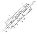
- FIG. 1shows an example of an enclosure 20 comprises two substantially symmetrical halves 22 , 24 held together by a fastening means including, but not limited to, screws, bolts, clamps, hooks or latches received through openings 21 .
- a rubber gasketoperable for providing a weatherproof seal may be disposed between the two halves 22 , 24 in a groove or channel defined by the two halves 22 , 24 .
- the exemplary enclosure 20has a generally cylindrical shape and defines a cavity 26 therein, hereinafter referred to as the “interior” of the enclosure 20 .
- the enclosuremay be of any size, shape or number of portions suitable for enclosing the access point and exposed buffer tubes.
- the region outside of the enclosure 20is hereinafter referred to as the “exterior” of the enclosure 20 .
- the enclosure 20defines horizontal cable pathway features 28 that extend from the end walls of the enclosure 20 in the axial direction.
- a distribution cable 30passes through and is routed by the horizontal cable pathway features 28 .
- the enclosure 20further defines at least one connector port 32 that opens through at least one end wall 34 of the enclosure 20 .
- the enclosure 20is shown having 4 connector ports 32 opening through only one housing or end wall 34 , it is envisioned that any number of connector ports 32 may open through either or both end walls.
- the connector ports 32are shown occupied by connector port covers 36 .
- a heat recoverable materialsuch as a heat shrink
- the heat shrinkmay further function to hold the two halves 22 , 24 together and maintain the position of the enclosure 20 over an access point along the cable length.
- the hear shrinkshould substantially cover the horizontal cable pathway defining features 28 and a portion of the distribution cable 30 .
- the “access point”is hereinafter defined as the point along the cable length at which the cable sheath has been removed to expose the underlying buffer tubes, thus permitting access to the buffer tubes encasing the optical fibers.
- the cable sheathmay be removed by ring cutting or by any technique known to those skilled in the art.
- the enclosure 20may be factory or field-installed.
- the distribution cable 30may have a plurality of factory preterminated connectors encased by a heat recoverable material 38 , such as a heat shrink material.
- a heat shrink materialmay be removed to expose the access point along the cable length and the plurality of preterminated connectors.
- the enclosure 20may then be installed over the access point and the preterminated connectors connected to their respective connector ports 32 .
- a distribution cable 30may have a plurality of enclosures attached at predetermined locations along the cable length with the preterminated connectors already attached to their respective connector ports 32 .
- the preterminated connectorsmay be directly terminated or spliced, which is discussed below in greater detail.
- the distribution cable 30with or without the enclosures 20 attached at predetermined locations, may be rolled onto a reel for distribution.
- the interior of the enclosure 20is of a volume sufficient to house and handle the distribution cable 30 , the accessed optical fibers, the preterminated connectors, a bend radius control means, optical fiber slack and splice holders that may be used with fusion splicing applications.
- the enclosure 20has a diameter just large enough to enclose the distribution cable, bend radius control means, optical fiber slack and sealing means. It is preferred that the enclosure 20 be long enough to completely encase the access point.
- the access pointis preferably from about 1 to about 15 inches in length, or long enough to access at least 1 inch of optical fiber.
- a factory-installed enclosure 20having a direct-terminated optical fiber 44 having a preterminated connector 40 and a tether means 42 for limiting the travel of the connector 40 exterior of the enclosure 20 .
- the tether means 42not only limits the amount of fiber 44 that can be removed from the enclosure 20 , but facilitates its replacement at the end of the cleaning or servicing operation. This may require an elastic tether with a tensile element operable for preventing fiber extension beyond a predetermined point.
- the tether means 42requires a structure inside the enclosure 20 that will allow the desired amount of fiber 44 to be withdrawn and reloaded without damage.
- the most simple tether embodimentmay comprise an enclosure housing defining a cavity capable of containing the fiber 44 at both installed and extended positions.
- the fiber 44may be pulled from the enclosure 20 using minimal force, the connector assembly cleaned and serviced, then the tether pulls the connector assembly back into the housing.
- a more complicated approachmay comprise a spring or elastomer element.
- using current enclosure designone also relies on the skill of the technician to get the fiber slack back into the enclosure 20 without damaging the fiber 44 or the contents of the enclosure 20 .
- the tether means 42limits the travel of the preterminated connector 40 exterior of the enclosure 20 .
- a hose clamp 48 and tether cord 50 secured to both the distribution cable 30 and the preterminated connector 40are the tether means 42 .
- the tether cord 50may be an inelastic or elastic material with a predetermined maximum extension distance.
- the extension distance of the tether means 42determines the extension distance of the preterminated connector 40 exterior of the enclosure 20 .
- the elasticitymay aid in the reloading of the preterminated connector 40 after it has been withdrawn from the enclosure interior 26 .
- the extension distance of the preterminated connector 40 from the connector port 32is preferably from about 1 to about 6 inches, and should not be less than about 1 inch. The extension distance should be adequate to allow access to the ferrule of the connector 40 for cleaning, polishing and replacing.
- the hose clamp 48 secured around the distribution cable sheathprovides an adequately strong anchoring point for the tether cord 50 . It is preferred that the hose clamp 48 be secured over the cable sheath so as not to damage the exposed buffer tubes.
- the tether means 42may be secured at one end to the optical fiber 44 , and secured at the other end to an interior surface of the enclosure housing.
- the enclosure 20is shown having a bend radius control means 46 secured to one half of the enclosure housing.
- the bend radius control means 46is operable for maintaining a minimum bend radius, preferably greater than about 1.5 inches, of the optical fibers 44 .
- the bend radius control means 46 shown in FIG. 2 ahas a cylindrical shape and may define grooves or channels on its outer surface which guides the optical fibers 44 around the outer surface.
- the preterminated connector 40is shown connected to one of the connector ports 32 that open through the end wall 34 of the enclosure 20 .
- a drop cablemay be connected to the exterior side of the connector port 32 , thus forming a preterminated connection.
- the drop cablesdo not enter the enclosure 20 .
- the connector port 32provides an adequately strong anchoring point for supporting the weight of the drop cable.
- the force applied to the connector port 32 from the weight of the drop cableis transferred from the connector port 32 to the enclosure 20 housing, which is secured by the distribution cable 30 and the heat shrink material secured around the pathway features 28 of the enclosure 20 .
- the force from the weight of the drop cableis not transferred to the preterminated connector 40 of the optical fiber 44 .
- a factory-installed enclosure 20is shown having factory fusion-spliced optical fibers 44 having preterminated connectors 40 and a tether means 42 for limiting the travel of the connectors 40 exterior of the enclosure 20 .
- the distribution cable 30is shown having the optical fibers 44 fusion-spliced at a low-profile access point.
- 4 preterminated connectors 40are shown, only one preterminated connector 40 is shown connected to the connector port 32 that opens through the end wall 34 of the enclosure 20 .
- a drop cablemay be connected to the exterior side of the connector port 32 , thus forming a preterminated connection. Again, the drop cables attach on the exterior of the enclosure 20 and do not enter the enclosure 20 .
- the connector port 32provides an adequately strong anchoring point for supporting the weight of the drop cable.
- the tether means 42limits the travel of the preterminated connectors 40 exterior of the enclosure 20 .
- the exemplary fusion-splice embodiment shown in FIG. 2 bwas prepared by the method described below.
- the fusion splice and method of producing the spliceare not intended to limit the invention, but serve as one example in which the distribution cable may be accessed and factory preterminated.
- the distribution cable 30 shownis a single-mode 2-72 fiber cable with 6 positions for the helically s-z stranded buffer tubes. This exemplary cable comprises 12 optical fibers 44 per tube.
- the buffer tubesmay be accessed by removing a substantial portion of the outer sheath encased by the enclosure 30 , as described above.
- a predetermined branched buffer tube 46may be accessed by ring cutting opposing ends and running the length of the tube with a blade that resides in a tool referred to as an “optical fiber access tool” (“OFAT”).
- the cut buffer portionmay then be removed, exposing the 12 optical fibers 44 .
- Each optical fiber 44may be comprised of a core, cladding and a coating, having sizes of about 8 microns, 125 microns and 250 microns in diameter, respectively.
- the exemplary splice shownillustrates the connectorization of 4 optical fibers 44 that connect to 4 connector ports 32 .
- the 8 remaining unused optical fibers 44may be removed.
- the optical fibers 44may be cleaned and prepared for splicing.
- Each optical fiber 44may be spliced together with a pre-connectorized “pigtail” into 4 pairs using a fusion splicer.
- a reinforced splice protector 52 for splice protectionmay be slid into the correct position, centered over the spliced intersection and shrunk permanently into place.
- the splice pointsmay be held in place using a splice holder 54 , such as a rubber or plastic material defining channels or grooves operable for holding a splice protector 52 in place.
- the splice holder 54may be secured to an interior surface of the enclosure housing or to the distribution cable 30 .
- the tether cord 50may be fixably attached to the optical fiber 44 and secured to either the distribution cable 30 or to an interior surface of the enclosure 20 .
- the position of the hose clamp 48 and the length of the tether cord 50determine the maximum extension distance of the connectors 40 exterior of the enclosure 20 .
- the extension distance of the preterminated connector 40 from the connector port 32is preferably from about 1 to about 6 inches, and should not be less than about 1 inch. The extension distance should be adequate to allow access to the ferrule of the connector 40 for cleaning, polishing, repairing and replacing.
- the hose clamp 48 tethered to either the distribution cable 30 or to an interior surface of the enclosure 20provides an adequately strong anchoring point for the connectors 40 of the optical fibers 44 .
- a sealing meanssuch as an invertable sealing boot 56 may simultaneously act to seal the backside of the connector port 32 and provide over-travel prevention capability.
- the sealing boot 56 in FIG. 3 ais shown in a retracted position in which the preterminated connector 40 is disposed in the interior 26 of the enclosure 20 .
- the length of the sealing boot 56determines an extension distance 58 of the connector 40 exterior of the enclosure 30 .
- the sealing function of the sealing boot 56protects the preterminated connection while allowing the rest of the enclosure 20 to remain unsealed. By using individual boot seals for each preterminated connection, it is insured that the sealing of other connectors 40 within the enclosure 20 are not affected while one connection is attended to.
- the sealing boot 56may be secured to its respective optical fiber 44 using a heat shrink, clamp, strap or other fastening mechanism.
- the sealing boot 56may be connected at its other end to a connector port receptacle 60 using a clamp, strap, interference fit or other fastening mechanism.
- the preterminated connector 40is connected to an adapter sleeve 62 that resides within the receptacle 60 secured to the connector port 32 .
- the adapter sleeve 62may be biased in the direction of the end wall 34 of the enclosure 20 and brings the ferrule of the preterminated connector 40 into contact with the ferrule of an attached drop cable.
- a receptacle cap 64fits securely within the receptacle 60 and is operable for holding the adapter sleeve 62 within the receptacle 60 .
- the receptacle cap 64preferably engages the receptacle 60 using a snap-fit design, but may comprise a screw-fit, bayonet-fit or any other interference-fit design.
- a removable connector port cover 36occupies the connector port 40 when a drop cable is not attached to the exterior surface of the adapter sleeve 62 .
- the connector port cover 36may be secured using a snap-fit, screw-fit, bayonet-fit or any other interference-fit design.
- the sealing boot 56is shown in an extended position in which the preterminated connector 40 is exterior of the enclosure 20 .
- the connector port cover 36 , the receptacle cap 64 and the adapter sleeve 62have been removed and are not shown.
- the sealing boot 56simultaneously acts to seal the backside of the connector port 32 and provides the over-travel prevention capability.
- a drop cablecomprising a similar sealing boot 56 may be connected to the exterior side of the adapter sleeve 62 to seal the preterminated connection.
- the preterminated connector 40is exterior of the enclosure 20 a distance determined by the length of the sealing boot extension distance 58 . The extension distance provides access to the connector 40 from the exterior of the enclosure 20 without having to enter the enclosure 20 .
- the sealing boot 56is secured to its respective optical fiber 44 and the connector port receptacle 60 .
- the sealing boot 56will revert to its retracted configuration when the preterminated connector 40 is reloaded into the enclosure 20 .
- the sealing boot 56is shown extended beyond the exterior surface of the connector port 32 , in an alternative embodiment, when inverted the sealing boot 56 may not be extended beyond the exterior surface so as not to damage the sealing boot 56 or pull it off of the receptacle 60 .
- FIG. 4 aanother embodiment of a tether means 42 and a bend radius control means 46 is shown for accessing a preterminated connector 40 from the exterior of an enclosure 20 .
- the sealing means illustrated in FIGS. 3 a and 3 bmay be used with the tether and bend radius control design of FIGS. 4 a and 4 b .
- the sealing boot 56may simultaneously act to seal the backside of the connector port 32 and provide optical fiber 44 over-travel prevention capability.
- a hardened connector with a sealing meanssuch as an o-ring, may be disposed between the exterior surface of the connector and the interior surface of the adapter sleeve 62 .
- a sealing meanssuch as an o-ring, may be disposed between the exterior surface of the adapter sleeve 62 and a connector of a drop cable.
- the sealing boot 56may be used alone or in combination with the o-ring sealing means.
- the preterminated connector 40 in FIG. 4 ais shown in a retracted position within the interior 26 of the enclosure 20 .
- a spring-loaded tether means 42may be used to provide tether and bend radius control functions. In addition, in tightly constrained spaces the spring may function as a means of pulling the connector 40 back into the enclosure 20 in the desired orientation. In enclosures 20 having a large interior, the means for pulling the connector 40 back into the enclosure 20 may not be needed.
- An optical fiber 44may be routed by a frictionless groove 66 defined by a first semicircular portion 68 of the tether means 42 .
- One or more helical springs 70 disposed between the first portion 68 and a second portion 72 of the tether means 42may be operable for providing tension between the two portions.
- the springs 70compress and the optical fiber 44 slides along the outer surface of the first portion 68 .
- the springsprovide a tension force for reloading the optical fiber slack.
- the length of the springs 70 and the amount that they can be compresseddetermines the extension distance 58 of the connector 40 exterior of the enclosure 30 .
- the sealing boot 56if used, may also determine the extension distance 58 .
- the tether means 42may be secured to the distribution cable 30 or to an interior surface of the enclosure 20 using any fastening means.
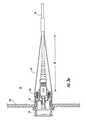
- FIG. 5 ashows an assembled view of another embodiment of a tether and bend radius control means 42 for accessing a preterminated connector 40 from the exterior of an enclosure 20 .
- An adapter sleeve 62 disposed within the connector port 32is connected to both the preterminated connector 40 and a drop cable 74 .
- Sealing boots 56are removably attached to the optical fibers 44 and the end wall 34 of the enclosure on both the preterminated connector 40 side and on the drop cable side to seal the preterminated connection.
- the sealing boots 56may be attached to the end wall 34 using a fastening means including, but not limited to, screws 76 or snaps. As stated above, the sealing boot 56 may simultaneously act to seal the connector port 32 and provide optical fiber 44 over-travel prevention capability.
- an additional sealing meanssuch as an o-ring, may be disposed between the exterior surface of the connector and the interior surface of the adapter sleeve 62 .
- a sealing meanssuch as an o-ring, may be disposed between the exterior surface of the adapter sleeve 62 and the connector of the drop cable.
- the preterminated connector 40 in FIG. 5 ais shown in a retracted position within the interior 26 of the enclosure 20 .
- a spring-loaded tether means 42may be used to provide tether, bend radius control and connector retraction functions.
- the optical fiber 44travels around the exterior of the coil spring 70 when slack is withdrawn or reloaded.
- the spring 70is fixed to an interior surface of the enclosure 20 or to the distribution cable 30 .
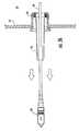
- FIG. 5 bshows the preterminated connection of FIG. 5 a in a disassembled and extended position.
- the spring 70compresses and the optical fiber 44 slides along the outer surface of the spring 70 .
- the drop cable 74 and the adapter sleeve 62are detached from the end wall 34 .
- the adapter sleeve 62may be attached to the exterior surface of the end wall 34 using screws. The drop cable and preterminated connectors 40 may be accessed for cleaning by inverting the sealing boot 56 upon itself and exposing the connectors.
- the length of the spring 70 and the amount that it can be coileddetermines the extension distance 58 of the connector 40 exterior of the enclosure 30 .
- the sealing boot 56may also determine the extension distance 58 .
- the spring 70should not compress to a diameter smaller than the minimum bend radius of the optical fiber 44 .
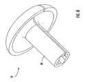
- a “mushroom” shaped apparatus 78may be secured around the distribution cable 30 at the predetermined branch position along the cable length.
- the branched optical fibers 44are routed over the surface of the cap-portion to their respective connector ports 32 .
- the bend-limiting apparatusmay be factory or field-installed.
- the apparatusmay comprise a spring 70 disposed between the apparatus shaft 80 and the distribution cable 30 , and fixed to the distribution cable.
- the spring 70provides a tether and a slack reloading function.
- the shaft 80may define grooves operable for channeling the optical fibers 44 along the distribution cable 30 .
- FIG. 7shows a specific embodiment of a receptacle assembly that resides within the connector port 32 .
- the receptacle 60is fixed to the end wall 34 of the enclosure 20 .
- the adapter sleeve 62resides within the receptacle 60 and is biased in the direction of the end wall 34 of the enclosure 20 .
- the adapter sleeve 62 and the preterminated connector 40are accessible from the exterior of the enclosure 20 .
- the adapter sleeve 62is held in place by the receptacle cap 64 that fits securely within the receptacle 60 .
- the receptacle cap 64preferably engages the receptacle 60 using a snap-fit design, but may comprise a screw-fit, bayonet-fit or any other interference-fit design.
- the removable connector port cover 36occupies the connector port 40 when a drop cable is not attached to the exterior surface of the adapter sleeve 62 .
- the connector port cover 36may be secured using a snap-fit, screw-fit, bayonet-fit or any other interference-fit design.
- FIG. 7is just one example of an assembly for connecting a preterminated connector pair, it is envisioned that other assemblies may perform similar functions.
Landscapes
- Physics & Mathematics (AREA)
- General Physics & Mathematics (AREA)
- Optics & Photonics (AREA)
- Light Guides In General And Applications Therefor (AREA)
- Mechanical Coupling Of Light Guides (AREA)
Abstract
Description
Claims (16)
Priority Applications (1)
| Application Number | Priority Date | Filing Date | Title |
|---|---|---|---|
| US10/674,696US6856748B1 (en) | 2003-09-30 | 2003-09-30 | Interconnection enclosure having a connector port and preterminated optical connector |
Applications Claiming Priority (1)
| Application Number | Priority Date | Filing Date | Title |
|---|---|---|---|
| US10/674,696US6856748B1 (en) | 2003-09-30 | 2003-09-30 | Interconnection enclosure having a connector port and preterminated optical connector |
Publications (1)
| Publication Number | Publication Date |
|---|---|
| US6856748B1true US6856748B1 (en) | 2005-02-15 |
Family
ID=34116819
Family Applications (1)
| Application Number | Title | Priority Date | Filing Date |
|---|---|---|---|
| US10/674,696Expired - Fee RelatedUS6856748B1 (en) | 2003-09-30 | 2003-09-30 | Interconnection enclosure having a connector port and preterminated optical connector |
Country Status (1)
| Country | Link |
|---|---|
| US (1) | US6856748B1 (en) |
Cited By (120)
| Publication number | Priority date | Publication date | Assignee | Title |
|---|---|---|---|---|
| US20050175307A1 (en)* | 2004-02-06 | 2005-08-11 | Battey Jennifer A. | Optical connection closure having at least one connector port |
| US20050180705A1 (en)* | 2003-12-15 | 2005-08-18 | Elkins Robert B.Ii | Pre-connectorized fiber optic distribution cable |
| US20060093303A1 (en)* | 2004-11-03 | 2006-05-04 | Randy Reagan | Fiber drop terminal |
| US20060133759A1 (en)* | 2004-12-22 | 2006-06-22 | Julian Mullaney | Optical fiber termination apparatus, entry sealing members and methods for using the same |
| US20060153516A1 (en)* | 2005-01-13 | 2006-07-13 | Napiorkowski John J | Network interface device having integral slack storage compartment |
| US20060233506A1 (en)* | 2005-04-19 | 2006-10-19 | Michael Noonan | Fiber breakout with integral connector |
| US20060233496A1 (en)* | 2005-04-15 | 2006-10-19 | Khemakhem M Hamed A | Hybrid fiber/copper connector system and method |
| US20060239691A1 (en)* | 2005-04-20 | 2006-10-26 | Tellabs Operations, Inc. | Optical transceiver with connector |
| WO2006115541A1 (en)* | 2005-04-22 | 2006-11-02 | Corning Cable Systems Llc | Methods and apparatus for facilitating cable locating by using transponder |
| US20060280420A1 (en)* | 2004-01-27 | 2006-12-14 | Blackwell Chois A Jr | Multi-port optical connection terminal |
| US20070122100A1 (en)* | 2005-11-30 | 2007-05-31 | Steven Day | Slack storage system |
| US20070127875A1 (en)* | 2005-12-06 | 2007-06-07 | Tyco Electronics Corporation | Optical Fiber Splicing Closures and Methods |
| US7251411B1 (en) | 2006-03-09 | 2007-07-31 | Adc Telecommunication, Inc. | Fiber optic cable breakout configuration with “Y” block |
| US20070212003A1 (en)* | 2006-03-09 | 2007-09-13 | Adc Telecommunications, Inc. | Mid-span breakout with potted closure |
| US20070212005A1 (en)* | 2006-03-09 | 2007-09-13 | Adc Telecommunications, Inc. | Mid-span breakout with helical fiber routing |
| US20070212009A1 (en)* | 2006-03-09 | 2007-09-13 | Adc Telecommunications, Inc. | Fiber optic cable breakout configuration with retention block |
| US7289714B1 (en) | 2006-09-26 | 2007-10-30 | Adc Telecommunication, Inc. | Tubing wrap procedure |
| US20080037945A1 (en)* | 2006-08-09 | 2008-02-14 | Jeff Gniadek | Cable payout systems and methods |
| US20080080818A1 (en)* | 2006-08-14 | 2008-04-03 | Cobb John C Iii | Factory Spliced Cable Assembly |
| US20080085091A1 (en)* | 2006-10-10 | 2008-04-10 | Dennis Ray Wells | Systems and methods for securing a tether to a distribution cable |
| US20080089652A1 (en)* | 2006-10-13 | 2008-04-17 | Dennis Ray Wells | Overmold zip strip |
| US20080124030A1 (en)* | 2006-11-29 | 2008-05-29 | Jarrod Scadden | Hybrid fiber/copper connector system and method |
| US20080124031A1 (en)* | 2006-11-29 | 2008-05-29 | Jarrod Scadden | Hybrid fiber/copper connector system and method |
| US20080187274A1 (en)* | 2007-02-06 | 2008-08-07 | Scott Carlson | Polyurethane to polyethylene adhesion process |
| US7418177B2 (en) | 2005-11-10 | 2008-08-26 | Adc Telecommunications, Inc. | Fiber optic cable breakout system, packaging arrangement, and method of installation |
| US7422378B2 (en) | 2006-03-09 | 2008-09-09 | Adc Telecommunications, Inc. | Fiber optic cable breakout configuration with excess fiber length |
| US20080219631A1 (en)* | 2007-03-08 | 2008-09-11 | Erik Gronvall | Universal bracket for mounting a drop terminal |
| US20080253722A1 (en)* | 2007-04-12 | 2008-10-16 | Erik Gronvall | Fiber optic telecommunications cable assembly |
| US20080253729A1 (en)* | 2007-04-12 | 2008-10-16 | Erik Gronvall | Fiber optic cable breakout configuration with tensile reinforcement |
| US20090022460A1 (en)* | 2006-08-14 | 2009-01-22 | Adc Telecommunications, Inc. | Factory Spliced Cable Assembly |
| KR100883227B1 (en)* | 2007-03-27 | 2009-02-17 | 주식회사 옵텔콤 | Fiber Optic Cable Connection Unit Grip Device |
| US20090060421A1 (en)* | 2007-03-16 | 2009-03-05 | 3M Innovative Properties Company | Optical fiber cable inlet device |
| US20090060419A1 (en)* | 2007-09-05 | 2009-03-05 | Adc Telecommunications, Inc. | Connector enclosure |
| US20090060431A1 (en)* | 2007-09-05 | 2009-03-05 | Yu Lu | Indoor Fiber Optic Distribution Cable |
| US20090060441A1 (en)* | 2007-09-05 | 2009-03-05 | Kowalczyk Scott C | Fiber optic enclosure with tear-away spool |
| US20090074360A1 (en)* | 2007-09-14 | 2009-03-19 | Seikoh Giken Co., Ltd. | Optical connector kit |
| US20090074370A1 (en)* | 2007-08-06 | 2009-03-19 | Adc Telecommunications, Inc. | Fiber optic enclosure with internal cable spool |
| US20090074369A1 (en)* | 2007-09-19 | 2009-03-19 | Albert Martin Bolton | Multi-port optical connection terminal |
| US20090202214A1 (en)* | 2007-12-11 | 2009-08-13 | Adc Telecommuniactions, Inc. | Wall box adapted to be mounted at a mid-span access location of a telecommunications cable |
| US20090238531A1 (en)* | 2008-01-09 | 2009-09-24 | Adc Telecommunications, Inc. | Wall box adapted to be mounted at a mid-span access location of a telecommunications cable |
| US20090252472A1 (en)* | 2008-02-15 | 2009-10-08 | Adc Telecommunications, Inc. | Fiber Optic Splice Enclosure |
| US20090252462A1 (en)* | 2008-04-08 | 2009-10-08 | Jean-Pierre Bonical | Optical box and method of connecting optical fibres |
| US7603020B1 (en)* | 2008-05-27 | 2009-10-13 | Emerson Network Power, Energy Systems, North America, Inc. | Cable clamp with integrated trace and bond capability |
| US20090269011A1 (en)* | 2007-11-30 | 2009-10-29 | Jarrod Scadden | Hybrid fiber/copper connector system and method |
| US20100059246A1 (en)* | 2008-05-27 | 2010-03-11 | Emerson Network Power, Energy Systems, North America, Inc. | Switched Grounding Assemblies |
| US7680388B2 (en) | 2004-11-03 | 2010-03-16 | Adc Telecommunications, Inc. | Methods for configuring and testing fiber drop terminals |
| US20100158453A1 (en)* | 2008-12-22 | 2010-06-24 | Joseph Todd Cody | Distribution Cable Assembly Having Mid-Span Access Location |
| US20100189404A1 (en)* | 2009-01-28 | 2010-07-29 | Adc Telecommunications, Inc. | Fiber optic enclosure |
| US20100239210A1 (en)* | 2009-03-20 | 2010-09-23 | Wakileh George I | Multipurpose Telecommunications Modules |
| US20110013875A1 (en)* | 2009-07-16 | 2011-01-20 | Adc Telecommunications, Inc. | Fiber optic enclosure with adapter bulkhead positioned beneath pivotal splice tray |
| US20110024544A1 (en)* | 2009-07-30 | 2011-02-03 | Mark Smrha | Locking spool for telecommunications cable and method |
| US20110024543A1 (en)* | 2009-07-30 | 2011-02-03 | Mark Smrha | Spool for telecommunications cable and method |
| US20110044599A1 (en)* | 2009-07-21 | 2011-02-24 | Adc Telecommunications, Inc. | Rapid universal rack mount enclosure |
| US20110217007A1 (en)* | 2010-03-04 | 2011-09-08 | Seikoh Giken Co., Ltd | Optical connector kit |
| WO2012018825A1 (en)* | 2010-08-02 | 2012-02-09 | Afl Telecommunications, Llc | Apparatus and method for preventing optical fiber and gel from ejecting out of buffer tubes in fiber optic cables |
| US20130058614A1 (en)* | 2010-05-03 | 2013-03-07 | Michael John Gimblet | Optical fiber cables having reversal point banding and methods of making thereof |
| WO2014015902A1 (en)* | 2012-07-25 | 2014-01-30 | Prysmian S.P.A. | Installation of a drop cable for an optical access network |
| US8720810B2 (en) | 2011-02-11 | 2014-05-13 | Adc Telecommunications, Inc. | Spool for telecommunications cable and method |
| US8755663B2 (en) | 2010-10-28 | 2014-06-17 | Corning Cable Systems Llc | Impact resistant fiber optic enclosures and related methods |
| WO2014113690A1 (en)* | 2013-01-17 | 2014-07-24 | Daigo Saito | Optical fiber transition structure |
| US8798417B2 (en) | 2012-09-26 | 2014-08-05 | Corning Cable Systems Llc | Binder film for a fiber optic cable |
| US8805144B1 (en) | 2013-09-24 | 2014-08-12 | Corning Optical Communications LLC | Stretchable fiber optic cable |
| US8837940B2 (en) | 2010-04-14 | 2014-09-16 | Adc Telecommunications, Inc. | Methods and systems for distributing fiber optic telecommunication services to local areas and for supporting distributed antenna systems |
| USRE45153E1 (en) | 2007-01-13 | 2014-09-23 | Adc Telecommunications, Inc. | Fiber optic cable distribution box |
| US8873926B2 (en) | 2012-04-26 | 2014-10-28 | Corning Cable Systems Llc | Fiber optic enclosures employing clamping assemblies for strain relief of cables, and related assemblies and methods |
| US8885998B2 (en) | 2010-12-09 | 2014-11-11 | Adc Telecommunications, Inc. | Splice enclosure arrangement for fiber optic cables |
| US8913862B1 (en) | 2013-09-27 | 2014-12-16 | Corning Optical Communications LLC | Optical communication cable |
| US8915659B2 (en) | 2010-05-14 | 2014-12-23 | Adc Telecommunications, Inc. | Splice enclosure arrangement for fiber optic cables |
| US8939654B2 (en) | 2012-09-27 | 2015-01-27 | Adc Telecommunications, Inc. | Ruggedized multi-fiber fiber optic connector with sealed dust cap |
| US9016953B2 (en) | 2012-02-20 | 2015-04-28 | Adc Telecommunications, Inc. | Fiber optic connector, fiber optic connector and cable assembly, and methods for manufacturing |
| US9057860B2 (en) | 2007-05-07 | 2015-06-16 | Adc Telecommunications, Inc. | Fiber optic enclosure with external cable spool |
| US20150168657A1 (en)* | 2012-06-15 | 2015-06-18 | Andrew Llc | Universal remote radio unit bird armored fiber optic cable assembly |
| US9069151B2 (en) | 2011-10-26 | 2015-06-30 | Corning Cable Systems Llc | Composite cable breakout assembly |
| US9075212B2 (en) | 2013-09-24 | 2015-07-07 | Corning Optical Communications LLC | Stretchable fiber optic cable |
| US9091830B2 (en) | 2012-09-26 | 2015-07-28 | Corning Cable Systems Llc | Binder film for a fiber optic cable |
| US9126802B2 (en) | 2012-04-30 | 2015-09-08 | Adc Telecommunications, Inc. | Payout spool with automatic cable disconnect/reconnect |
| US9140867B1 (en) | 2013-08-09 | 2015-09-22 | Corning Optical Communications LLC | Armored optical fiber cable |
| WO2015153323A1 (en)* | 2014-04-04 | 2015-10-08 | Corning Optical Communications LLC | Fiber optic cable assembly |
| US9188760B2 (en) | 2011-12-22 | 2015-11-17 | Adc Telecommunications, Inc. | Mini rapid delivery spool |
| US9261663B2 (en) | 2010-06-18 | 2016-02-16 | Adc Communications (Shanghai) Co., Ltd. | Fiber optic distribution terminal and method of deploying fiber distribution cable |
| US9268102B2 (en) | 2012-02-07 | 2016-02-23 | Tyco Electronics Raychem Bvba | Cable termination assembly and method for connectors |
| WO2016033048A1 (en)* | 2014-08-26 | 2016-03-03 | Commscope Technologies Llc | Sealing unit for fiber optic interconnections |
| US9304262B2 (en) | 2011-11-23 | 2016-04-05 | Commscope Technologies Llc | Multi-fiber optic connector |
| US9500831B2 (en) | 2012-04-30 | 2016-11-22 | Commscope Technologies Llc | Cable payout cassette with single layer cable storage area |
| US9594226B2 (en) | 2013-10-18 | 2017-03-14 | Corning Optical Communications LLC | Optical fiber cable with reinforcement |
| US9722407B2 (en) | 2012-04-30 | 2017-08-01 | Commscope Technologies Llc | Guided cable storage assembly with switchbacks |
| US9720185B2 (en) | 2014-05-23 | 2017-08-01 | Commscope Technologies Llc | Systems and method for processing optical cable assemblies |
| WO2018002743A3 (en)* | 2016-07-01 | 2018-02-22 | 3M Innovative Properties Company | Multi-purpose sealing device |
| US9908742B2 (en) | 2012-04-30 | 2018-03-06 | Commscope Technologies Llc | Cable storage spool with center feed |
| US20180100982A1 (en)* | 2013-04-07 | 2018-04-12 | Adc Telecommunications (Shanghai) Distribution Co., Ltd. | Fiber optic connection assembly |
| US9977211B1 (en) | 2017-04-21 | 2018-05-22 | Afl Telecommunications Llc | Optical connection terminals for fiber optic communications networks |
| US9995898B2 (en) | 2010-06-23 | 2018-06-12 | Commscope Technologies Llc | Telecommunications assembly |
| US10054741B2 (en) | 2015-10-14 | 2018-08-21 | Commscope Technologies Llc | Fiber optic enclosure assembly |
| US10281670B2 (en) | 2015-01-12 | 2019-05-07 | Afl Telecommunications Llc | Fiber optic terminal enclosure |
| US10371914B2 (en) | 2011-06-24 | 2019-08-06 | Commscope Technologies Llc | Fiber termination enclosure with modular plate assemblies |
| US10444462B2 (en) | 2014-11-21 | 2019-10-15 | Commscope Telecommunications (Shanghai) Co. Ltd. | Optical cable wiring system and optical cable connecting component |
| US10520692B2 (en) | 2015-11-11 | 2019-12-31 | Afl Telecommunications Llc | Optical connection terminals for fiber optic communications networks |
| US10545305B2 (en) | 2012-12-19 | 2020-01-28 | CommScope Connectivity Belgium BVBA | Distribution device with incrementally added splitters |
| US11187859B2 (en) | 2017-06-28 | 2021-11-30 | Corning Research & Development Corporation | Fiber optic connectors and methods of making the same |
| US11215768B2 (en) | 2017-06-28 | 2022-01-04 | Corning Research & Development Corporation | Fiber optic connectors and connectorization employing adhesive admitting adapters |
| US11287589B2 (en) | 2012-09-26 | 2022-03-29 | Corning Optical Communications LLC | Binder film for a fiber optic cable |
| US11294133B2 (en) | 2019-07-31 | 2022-04-05 | Corning Research & Development Corporation | Fiber optic networks using multiports and cable assemblies with cable-to-connector orientation |
| US11300746B2 (en) | 2017-06-28 | 2022-04-12 | Corning Research & Development Corporation | Fiber optic port module inserts, assemblies and methods of making the same |
| US11487073B2 (en) | 2019-09-30 | 2022-11-01 | Corning Research & Development Corporation | Cable input devices having an integrated locking feature and assemblies using the cable input devices |
| US11536921B2 (en) | 2020-02-11 | 2022-12-27 | Corning Research & Development Corporation | Fiber optic terminals having one or more loopback assemblies |
| US11604320B2 (en) | 2020-09-30 | 2023-03-14 | Corning Research & Development Corporation | Connector assemblies for telecommunication enclosures |
| US11650388B2 (en) | 2019-11-14 | 2023-05-16 | Corning Research & Development Corporation | Fiber optic networks having a self-supporting optical terminal and methods of installing the optical terminal |
| US11668890B2 (en) | 2017-06-28 | 2023-06-06 | Corning Research & Development Corporation | Multiports and other devices having optical connection ports with securing features and methods of making the same |
| US11686913B2 (en) | 2020-11-30 | 2023-06-27 | Corning Research & Development Corporation | Fiber optic cable assemblies and connector assemblies having a crimp ring and crimp body and methods of fabricating the same |
| US11703646B2 (en) | 2017-06-28 | 2023-07-18 | Corning Research & Development Corporation | Multiports and optical connectors with rotationally discrete locking and keying features |
| US20230358987A1 (en)* | 2020-07-07 | 2023-11-09 | Commscope Technologies Llc | Fiber optic splice transitions and methods of assembly |
| US11880076B2 (en) | 2020-11-30 | 2024-01-23 | Corning Research & Development Corporation | Fiber optic adapter assemblies including a conversion housing and a release housing |
| US11886010B2 (en) | 2019-10-07 | 2024-01-30 | Corning Research & Development Corporation | Fiber optic terminals and fiber optic networks having variable ratio couplers |
| US11927810B2 (en) | 2020-11-30 | 2024-03-12 | Corning Research & Development Corporation | Fiber optic adapter assemblies including a conversion housing and a release member |
| US11947167B2 (en) | 2021-05-26 | 2024-04-02 | Corning Research & Development Corporation | Fiber optic terminals and tools and methods for adjusting a split ratio of a fiber optic terminal |
| US11994722B2 (en) | 2020-11-30 | 2024-05-28 | Corning Research & Development Corporation | Fiber optic adapter assemblies including an adapter housing and a locking housing |
| US12019279B2 (en) | 2019-05-31 | 2024-06-25 | Corning Research & Development Corporation | Multiports and other devices having optical connection ports with sliding actuators and methods of making the same |
| US12044894B2 (en) | 2018-12-28 | 2024-07-23 | Corning Research & Development Corporation | Multiport assemblies including mounting features or dust plugs |
| US12271040B2 (en) | 2017-06-28 | 2025-04-08 | Corning Research & Development Corporation | Fiber optic extender ports, assemblies and methods of making the same |
| US12372727B2 (en) | 2020-10-30 | 2025-07-29 | Corning Research & Development Corporation | Female fiber optic connectors having a rocker latch arm and methods of making the same |
Citations (14)
| Publication number | Priority date | Publication date | Assignee | Title |
|---|---|---|---|---|
| US4961623A (en) | 1989-09-05 | 1990-10-09 | Siecor Corporation | Preterminated optical cable |
| US4978086A (en)* | 1987-06-02 | 1990-12-18 | Stc Plc | Deployment of towed aircraft decoys |
| US5042901A (en) | 1990-07-31 | 1991-08-27 | Siecor Corporation | Preconnectorized optical splice closure |
| US5121458A (en) | 1991-04-05 | 1992-06-09 | Alcatel Na Cable Systems, Inc. | Preterminated fiber optic cable |
| US5125060A (en) | 1991-04-05 | 1992-06-23 | Alcatel Na Cable Systems, Inc. | Fiber optic cable having spliceless fiber branch and method of making |
| US5133032A (en)* | 1991-04-17 | 1992-07-21 | Salter James R | Optical fiber connector |
| US5210812A (en) | 1991-04-05 | 1993-05-11 | Alcatel Na Cable Systems, Inc. | Optical fiber cable having spliced fiber branch and method of making the same |
| US5440665A (en) | 1993-04-16 | 1995-08-08 | Raychem Corporation | Fiber optic cable system including main and drop cables and associated fabrication method |
| US5696864A (en)* | 1996-09-18 | 1997-12-09 | Communications Technology Corporation | Aerial enclosure for coupling data signals to a customer site |
| US5742718A (en)* | 1996-08-13 | 1998-04-21 | Eclipse Surgical Technologies, Inc. | Proprietary fiber connector and electronic security system |
| US5778122A (en) | 1996-12-24 | 1998-07-07 | Siecor Corporation | Fiber optic cable assembly for interconnecting optical fibers within a receptacle mounted within the wall of an enclosure |
| US5892870A (en) | 1995-11-16 | 1999-04-06 | Fiber Connections Inc. | Fibre optic cable connector |
| USRE37028E1 (en) | 1994-02-02 | 2001-01-23 | Siecor Corporation | Cable assembly for use with opto-electronic equipment enclosures |
| US6579014B2 (en) | 2001-09-28 | 2003-06-17 | Corning Cable Systems Llc | Fiber optic receptacle |
- 2003
- 2003-09-30USUS10/674,696patent/US6856748B1/ennot_activeExpired - Fee Related
Patent Citations (15)
| Publication number | Priority date | Publication date | Assignee | Title |
|---|---|---|---|---|
| US4978086A (en)* | 1987-06-02 | 1990-12-18 | Stc Plc | Deployment of towed aircraft decoys |
| US4961623A (en) | 1989-09-05 | 1990-10-09 | Siecor Corporation | Preterminated optical cable |
| US5042901A (en) | 1990-07-31 | 1991-08-27 | Siecor Corporation | Preconnectorized optical splice closure |
| US5210812A (en) | 1991-04-05 | 1993-05-11 | Alcatel Na Cable Systems, Inc. | Optical fiber cable having spliced fiber branch and method of making the same |
| US5125060A (en) | 1991-04-05 | 1992-06-23 | Alcatel Na Cable Systems, Inc. | Fiber optic cable having spliceless fiber branch and method of making |
| US5121458A (en) | 1991-04-05 | 1992-06-09 | Alcatel Na Cable Systems, Inc. | Preterminated fiber optic cable |
| US5133032A (en)* | 1991-04-17 | 1992-07-21 | Salter James R | Optical fiber connector |
| US5440665A (en) | 1993-04-16 | 1995-08-08 | Raychem Corporation | Fiber optic cable system including main and drop cables and associated fabrication method |
| US5528718A (en) | 1993-04-16 | 1996-06-18 | Raychem Corporation | Fiber optic cable system including main and drop cables and associated fabrication method |
| USRE37028E1 (en) | 1994-02-02 | 2001-01-23 | Siecor Corporation | Cable assembly for use with opto-electronic equipment enclosures |
| US5892870A (en) | 1995-11-16 | 1999-04-06 | Fiber Connections Inc. | Fibre optic cable connector |
| US5742718A (en)* | 1996-08-13 | 1998-04-21 | Eclipse Surgical Technologies, Inc. | Proprietary fiber connector and electronic security system |
| US5696864A (en)* | 1996-09-18 | 1997-12-09 | Communications Technology Corporation | Aerial enclosure for coupling data signals to a customer site |
| US5778122A (en) | 1996-12-24 | 1998-07-07 | Siecor Corporation | Fiber optic cable assembly for interconnecting optical fibers within a receptacle mounted within the wall of an enclosure |
| US6579014B2 (en) | 2001-09-28 | 2003-06-17 | Corning Cable Systems Llc | Fiber optic receptacle |
Cited By (344)
| Publication number | Priority date | Publication date | Assignee | Title |
|---|---|---|---|---|
| US20050180705A1 (en)* | 2003-12-15 | 2005-08-18 | Elkins Robert B.Ii | Pre-connectorized fiber optic distribution cable |
| US7016592B2 (en)* | 2003-12-15 | 2006-03-21 | Corning Cable Systems Llc | Fiber optic communications network comprising pre-connectorized fiber optic distribution cable |
| US20060280420A1 (en)* | 2004-01-27 | 2006-12-14 | Blackwell Chois A Jr | Multi-port optical connection terminal |
| US20080069511A1 (en)* | 2004-01-27 | 2008-03-20 | Blackwell Chois A Jr | Multi-port optical connection terminal |
| US7333708B2 (en)* | 2004-01-27 | 2008-02-19 | Corning Cable Systems Llc | Multi-port optical connection terminal |
| US7653282B2 (en) | 2004-01-27 | 2010-01-26 | Corning Cable Systems Llc | Multi-port optical connection terminal |
| US7013074B2 (en)* | 2004-02-06 | 2006-03-14 | Corning Cable Systems Llc | Optical connection closure having at least one connector port |
| US20050175307A1 (en)* | 2004-02-06 | 2005-08-11 | Battey Jennifer A. | Optical connection closure having at least one connector port |
| US20060093304A1 (en)* | 2004-02-06 | 2006-05-04 | Battey Jennifer A | Optical connection closure having at least one connector port |
| US20080112681A1 (en)* | 2004-02-06 | 2008-05-15 | Battey Jennifer A | Optical connection closure having at least one connector port |
| US7869681B2 (en)* | 2004-02-06 | 2011-01-11 | Corning Cable Systems Llc | Optical connection closure having at least one connector port for optically connecting a drop cable to a distribution cable |
| US7680388B2 (en) | 2004-11-03 | 2010-03-16 | Adc Telecommunications, Inc. | Methods for configuring and testing fiber drop terminals |
| US10890729B2 (en) | 2004-11-03 | 2021-01-12 | Commscope Technologies Llc | Fiber drop terminal and bracket |
| US7489849B2 (en) | 2004-11-03 | 2009-02-10 | Adc Telecommunications, Inc. | Fiber drop terminal |
| US7805044B2 (en)* | 2004-11-03 | 2010-09-28 | Adc Telecommunications, Inc. | Fiber drop terminal |
| US10042136B2 (en)* | 2004-11-03 | 2018-08-07 | Commscope Technologies Llc | Fiber drop terminal |
| US11567278B2 (en) | 2004-11-03 | 2023-01-31 | Commscope Technologies Llc | Fiber drop terminal |
| US20100284662A1 (en)* | 2004-11-03 | 2010-11-11 | Adc Telecommunications, Inc. | Fiber drop terminal |
| US20080138025A1 (en)* | 2004-11-03 | 2008-06-12 | Fiber Optics Network Solutions Corporation | Fiber Drop Terminal |
| US12204157B2 (en) | 2004-11-03 | 2025-01-21 | Commscope Technologies Llc | Fiber drop terminal |
| US20090148120A1 (en)* | 2004-11-03 | 2009-06-11 | Adc Telecommunications, Inc. | Fiber drop terminal |
| US7627222B2 (en) | 2004-11-03 | 2009-12-01 | Adc Telecommunications, Inc. | Fiber drop terminal |
| US9851522B2 (en) | 2004-11-03 | 2017-12-26 | Commscope Technologies Llc | Fiber drop terminal |
| US20060093303A1 (en)* | 2004-11-03 | 2006-05-04 | Randy Reagan | Fiber drop terminal |
| US20060133759A1 (en)* | 2004-12-22 | 2006-06-22 | Julian Mullaney | Optical fiber termination apparatus, entry sealing members and methods for using the same |
| US20060153516A1 (en)* | 2005-01-13 | 2006-07-13 | Napiorkowski John J | Network interface device having integral slack storage compartment |
| US20090180739A1 (en)* | 2005-04-15 | 2009-07-16 | Adc Telecommunications, Inc. | Hybrid fiber/copper connector system and method |
| US7798725B2 (en) | 2005-04-15 | 2010-09-21 | Adc Telecommunications, Inc. | Hybrid fiber/copper connector system and method |
| US7393144B2 (en)* | 2005-04-15 | 2008-07-01 | Adc Telecommunications, Inc. | Hybrid fiber/copper connector system and method |
| US20060233496A1 (en)* | 2005-04-15 | 2006-10-19 | Khemakhem M Hamed A | Hybrid fiber/copper connector system and method |
| US11347008B2 (en) | 2005-04-19 | 2022-05-31 | Commscope Technologies Llc | Fiber optic connection device with ruggedized tethers |
| US7349605B2 (en) | 2005-04-19 | 2008-03-25 | Adc Telecommunications, Inc. | Fiber breakout with radio frequency identification device |
| US20100014824A1 (en)* | 2005-04-19 | 2010-01-21 | Adc Telecommunications, Inc. | Loop back plug and method |
| US7565055B2 (en) | 2005-04-19 | 2009-07-21 | Adc Telecommunications, Inc. | Loop back plug and method |
| US8041178B2 (en) | 2005-04-19 | 2011-10-18 | Adc Telecommunications, Inc. | Loop back plug and method |
| US20060257092A1 (en)* | 2005-04-19 | 2006-11-16 | Yu Lu | Loop back plug and method |
| US20060233506A1 (en)* | 2005-04-19 | 2006-10-19 | Michael Noonan | Fiber breakout with integral connector |
| US20060239691A1 (en)* | 2005-04-20 | 2006-10-26 | Tellabs Operations, Inc. | Optical transceiver with connector |
| WO2006115541A1 (en)* | 2005-04-22 | 2006-11-02 | Corning Cable Systems Llc | Methods and apparatus for facilitating cable locating by using transponder |
| US7418177B2 (en) | 2005-11-10 | 2008-08-26 | Adc Telecommunications, Inc. | Fiber optic cable breakout system, packaging arrangement, and method of installation |
| US7433570B2 (en)* | 2005-11-30 | 2008-10-07 | Tunnel Mill Polymer, Inc. | Slack storage system |
| US20070122100A1 (en)* | 2005-11-30 | 2007-05-31 | Steven Day | Slack storage system |
| US7393148B2 (en)* | 2005-12-06 | 2008-07-01 | Tyco Electronics Corporation | Optical fiber splicing closures and methods |
| US20070127875A1 (en)* | 2005-12-06 | 2007-06-07 | Tyco Electronics Corporation | Optical Fiber Splicing Closures and Methods |
| US7251411B1 (en) | 2006-03-09 | 2007-07-31 | Adc Telecommunication, Inc. | Fiber optic cable breakout configuration with “Y” block |
| US20070212005A1 (en)* | 2006-03-09 | 2007-09-13 | Adc Telecommunications, Inc. | Mid-span breakout with helical fiber routing |
| US20090022459A1 (en)* | 2006-03-09 | 2009-01-22 | Adc Telecommunications, Inc. | Fiber optic cable breakout configuration with retention block |
| US7590321B2 (en) | 2006-03-09 | 2009-09-15 | Adc Telecommunications, Inc. | Mid-span breakout with helical fiber routing |
| US7630606B2 (en) | 2006-03-09 | 2009-12-08 | Adc Telecommunications, Inc. | Fiber optic cable breakout configuration with retention block |
| US7317863B2 (en) | 2006-03-09 | 2008-01-08 | Adc Telecommunications, Inc. | Fiber optic cable breakout configuration with retention block |
| US20070212003A1 (en)* | 2006-03-09 | 2007-09-13 | Adc Telecommunications, Inc. | Mid-span breakout with potted closure |
| US7422378B2 (en) | 2006-03-09 | 2008-09-09 | Adc Telecommunications, Inc. | Fiber optic cable breakout configuration with excess fiber length |
| US20100080514A1 (en)* | 2006-03-09 | 2010-04-01 | Adc Telecommunications, Inc. | Fiber optic cable breakout configuration with retention block |
| US7424189B2 (en) | 2006-03-09 | 2008-09-09 | Adc Telecommunications, Inc. | Mid-span breakout with potted closure |
| US20070212009A1 (en)* | 2006-03-09 | 2007-09-13 | Adc Telecommunications, Inc. | Fiber optic cable breakout configuration with retention block |
| US20080037945A1 (en)* | 2006-08-09 | 2008-02-14 | Jeff Gniadek | Cable payout systems and methods |
| US8121456B2 (en) | 2006-08-09 | 2012-02-21 | Adc Telecommunications, Inc. | Cable payout systems and methods |
| US7599598B2 (en) | 2006-08-09 | 2009-10-06 | Adc Telecommunications, Inc. | Cable payout systems and methods |
| US7454106B2 (en) | 2006-08-14 | 2008-11-18 | Adc Telecommunications, Inc. | Factory spliced cable assembly |
| US20080080818A1 (en)* | 2006-08-14 | 2008-04-03 | Cobb John C Iii | Factory Spliced Cable Assembly |
| US7840109B2 (en) | 2006-08-14 | 2010-11-23 | Adc Telecommunications, Inc. | Factory spliced cable assembly |
| US20090022460A1 (en)* | 2006-08-14 | 2009-01-22 | Adc Telecommunications, Inc. | Factory Spliced Cable Assembly |
| US7289714B1 (en) | 2006-09-26 | 2007-10-30 | Adc Telecommunication, Inc. | Tubing wrap procedure |
| US20080085091A1 (en)* | 2006-10-10 | 2008-04-10 | Dennis Ray Wells | Systems and methods for securing a tether to a distribution cable |
| US7480436B2 (en) | 2006-10-10 | 2009-01-20 | Adc Telecommunications, Inc. | Systems and methods for securing a tether to a distribution cable |
| US20080089652A1 (en)* | 2006-10-13 | 2008-04-17 | Dennis Ray Wells | Overmold zip strip |
| US7403685B2 (en) | 2006-10-13 | 2008-07-22 | Adc Telecommunications, Inc. | Overmold zip strip |
| US7481585B2 (en) | 2006-11-29 | 2009-01-27 | Adc Telecommunications, Inc. | Hybrid fiber/copper connector system and method |
| US20090238519A1 (en)* | 2006-11-29 | 2009-09-24 | Adc Telecommunication, Inc. | Hybrid fiber/copper connector system and method |
| US20080124030A1 (en)* | 2006-11-29 | 2008-05-29 | Jarrod Scadden | Hybrid fiber/copper connector system and method |
| US20080124031A1 (en)* | 2006-11-29 | 2008-05-29 | Jarrod Scadden | Hybrid fiber/copper connector system and method |
| US7490994B2 (en) | 2006-11-29 | 2009-02-17 | Adc Telecommunications, Inc. | Hybrid fiber/copper connector system and method |
| US8113720B2 (en) | 2006-11-29 | 2012-02-14 | Adc Telecommunications, Inc. | Hybrid fiber/copper connector system and method |
| US8113722B2 (en) | 2006-11-29 | 2012-02-14 | Adc Telecommunications, Inc. | Hybrid fiber/copper connector system and method |
| USRE45153E1 (en) | 2007-01-13 | 2014-09-23 | Adc Telecommunications, Inc. | Fiber optic cable distribution box |
| USRE48063E1 (en) | 2007-01-13 | 2020-06-23 | Commscope Technologies Llc | Fiber optic cable distribution box |
| USRE49385E1 (en) | 2007-01-13 | 2023-01-24 | Commscope Technologies Llc | Fiber optic cable distribution box |
| USRE46255E1 (en) | 2007-01-13 | 2016-12-27 | Commscope Technologies Llc | Fiber optic cable distribution box |
| US7489843B2 (en) | 2007-02-06 | 2009-02-10 | Adc Telecommunications, Inc. | Polyurethane to polyethylene adhesion process |
| US20080187274A1 (en)* | 2007-02-06 | 2008-08-07 | Scott Carlson | Polyurethane to polyethylene adhesion process |
| US7558458B2 (en) | 2007-03-08 | 2009-07-07 | Adc Telecommunications, Inc. | Universal bracket for mounting a drop terminal |
| US20080219631A1 (en)* | 2007-03-08 | 2008-09-11 | Erik Gronvall | Universal bracket for mounting a drop terminal |
| US20090060421A1 (en)* | 2007-03-16 | 2009-03-05 | 3M Innovative Properties Company | Optical fiber cable inlet device |
| US20100086260A1 (en)* | 2007-03-16 | 2010-04-08 | Parikh Rutesh D | Optical fiber cable inlet device and telecommunications enclosure system |
| US7738759B2 (en) | 2007-03-16 | 2010-06-15 | 3M Innovative Properties Company | Optical fiber cable inlet device |
| US8879883B2 (en) | 2007-03-16 | 2014-11-04 | 3M Innovative Properties Company | Optical fiber cable inlet device and telecommunications enclosure system |
| KR100883227B1 (en)* | 2007-03-27 | 2009-02-17 | 주식회사 옵텔콤 | Fiber Optic Cable Connection Unit Grip Device |
| US20080253722A1 (en)* | 2007-04-12 | 2008-10-16 | Erik Gronvall | Fiber optic telecommunications cable assembly |
| US7532799B2 (en) | 2007-04-12 | 2009-05-12 | Adc Telecommunications | Fiber optic telecommunications cable assembly |
| US7609925B2 (en) | 2007-04-12 | 2009-10-27 | Adc Telecommunications, Inc. | Fiber optic cable breakout configuration with tensile reinforcement |
| US20080253729A1 (en)* | 2007-04-12 | 2008-10-16 | Erik Gronvall | Fiber optic cable breakout configuration with tensile reinforcement |
| US11009671B2 (en) | 2007-05-07 | 2021-05-18 | Commscope Technologies Llc | Fiber optic assembly with cable storage arrangement |
| US10627592B2 (en) | 2007-05-07 | 2020-04-21 | Commscope Technologies Llc | Fiber optic assembly with cable spool |
| US12235506B2 (en) | 2007-05-07 | 2025-02-25 | Commscope Technologies Llc | Fiber optic enclosure with external cable spool |
| US10788642B2 (en) | 2007-05-07 | 2020-09-29 | Commscope Technologies Llc | Fiber optic assembly with cable storage arrangement |
| US9057860B2 (en) | 2007-05-07 | 2015-06-16 | Adc Telecommunications, Inc. | Fiber optic enclosure with external cable spool |
| US9535227B2 (en) | 2007-05-07 | 2017-01-03 | Commscope Technologies Llc | Fiber optic cable spool assembly |
| US8494333B2 (en) | 2007-08-06 | 2013-07-23 | Adc Telecommunications, Inc. | Dispensing cable from an internal cable spool of a fiber optic enclosure |
| US9606319B2 (en) | 2007-08-06 | 2017-03-28 | Commscope Technologies Llc | Fiber optic enclosure with internal cable spool |
| US10712518B2 (en) | 2007-08-06 | 2020-07-14 | Commscope Technologies Llc | Fiber optic enclosure with lockable internal cable spool |
| US12253734B2 (en) | 2007-08-06 | 2025-03-18 | Commscope Technologies Llc | Fiber optic enclosure with internal cable spool |
| US10606017B2 (en) | 2007-08-06 | 2020-03-31 | Commscope Technologies Llc | Fiber optic payout assembly including cable spool |
| US10996417B2 (en) | 2007-08-06 | 2021-05-04 | Commscope Technologies Llc | Fiber optic enclosure with internal cable spool and movable cover |
| US10606015B2 (en) | 2007-08-06 | 2020-03-31 | Commscope Technologies Llc | Fiber optic payout assembly including cable spool |
| US8705929B2 (en) | 2007-08-06 | 2014-04-22 | Adc Telecommunications, Inc. | Fiber optic enclosure with internal cable spool |
| US10234648B2 (en) | 2007-08-06 | 2019-03-19 | Commscope Technologies Llc | Fiber optic enclosure with internal cable spool |
| US7894701B2 (en) | 2007-08-06 | 2011-02-22 | Adc Telecommunications, Inc. | Fiber optic enclosure with internal cable spool |
| US8891931B2 (en) | 2007-08-06 | 2014-11-18 | Adc Telecommunications, Inc. | Fiber optic enclosure with internal cable spool |
| US10996418B2 (en) | 2007-08-06 | 2021-05-04 | Commscope Technologies Llc | Connecting subscribers to a fiber optic network using a cable spool |
| US10895705B2 (en) | 2007-08-06 | 2021-01-19 | Commscope Technologies Llc | Fiber optic enclosure with internal cable spool |
| US9261666B2 (en) | 2007-08-06 | 2016-02-16 | Commscope Technologies Llc | Fiber optic enclosure with internal cable spool |
| US20110158599A1 (en)* | 2007-08-06 | 2011-06-30 | Adc Telecommunications, Inc. | Fiber optic enclosure with internal cable spool |
| US10247897B2 (en) | 2007-08-06 | 2019-04-02 | Commscope Technologies Llc | Fiber optic enclosure with internal cable spool |
| US12019301B2 (en) | 2007-08-06 | 2024-06-25 | Commscope Technologies Llc | Fiber optic enclosure with internal cable spool |
| US10495836B2 (en) | 2007-08-06 | 2019-12-03 | Commscope Technologies Llc | Fiber optic payout assembly including cable spool |
| US11573390B2 (en) | 2007-08-06 | 2023-02-07 | Commscope Technologies Llc | Fiber optic enclosure with internal cable spool |
| US20090074370A1 (en)* | 2007-08-06 | 2009-03-19 | Adc Telecommunications, Inc. | Fiber optic enclosure with internal cable spool |
| US7756379B2 (en) | 2007-08-06 | 2010-07-13 | Adc Telecommunications, Inc. | Fiber optic enclosure with internal cable spool |
| US20100310224A1 (en)* | 2007-08-06 | 2010-12-09 | Adc Telecommunications, Inc. | Fiber optic enclosure with internal cable spool |
| US8189984B2 (en) | 2007-08-06 | 2012-05-29 | Adc Telecommunications, Inc. | Fiber optic enclosure with internal cable spool |
| US20110091180A1 (en)* | 2007-09-05 | 2011-04-21 | Adc Telecommunications, Inc. | Fiber optic enclosure with tear-away spool |
| US8494334B2 (en) | 2007-09-05 | 2013-07-23 | Adc Telecommunications, Inc. | Fiber optic enclosure with tear-away spool |
| US20100329610A1 (en)* | 2007-09-05 | 2010-12-30 | Adc Telecommunications Inc. | Connector enclosure |
| US8229267B2 (en) | 2007-09-05 | 2012-07-24 | Adc Telecommunications, Inc. | Fiber optic enclosure with tear-away spool |
| US20090060441A1 (en)* | 2007-09-05 | 2009-03-05 | Kowalczyk Scott C | Fiber optic enclosure with tear-away spool |
| US8272787B2 (en)* | 2007-09-05 | 2012-09-25 | Adc Telecommunications, Inc. | Connector enclosure |
| US9563032B2 (en) | 2007-09-05 | 2017-02-07 | Commscope Technologies Llc | Fiber optic enclosure with tear-away spool |
| US8774588B2 (en) | 2007-09-05 | 2014-07-08 | Adc Telecommunications, Inc. | Fiber optic enclosure with tear-away spool |
| US7869682B2 (en) | 2007-09-05 | 2011-01-11 | Adc Telecommunications, Inc. | Fiber optic enclosure with tear-away spool |
| US9229185B2 (en) | 2007-09-05 | 2016-01-05 | Commscope Technologies Llc | Fiber optic enclosure with tear-away spool |
| US20090060419A1 (en)* | 2007-09-05 | 2009-03-05 | Adc Telecommunications, Inc. | Connector enclosure |
| US20090060431A1 (en)* | 2007-09-05 | 2009-03-05 | Yu Lu | Indoor Fiber Optic Distribution Cable |
| US7744287B2 (en)* | 2007-09-05 | 2010-06-29 | Adc Telecommunications, Inc. | Connector enclosure |
| US7769261B2 (en) | 2007-09-05 | 2010-08-03 | Adc Telecommunications, Inc. | Fiber optic distribution cable |
| US20090074360A1 (en)* | 2007-09-14 | 2009-03-19 | Seikoh Giken Co., Ltd. | Optical connector kit |
| US7860363B2 (en)* | 2007-09-14 | 2010-12-28 | Seikoh Giken Co., Ltd. | Optical connector kit |
| US20090074369A1 (en)* | 2007-09-19 | 2009-03-19 | Albert Martin Bolton | Multi-port optical connection terminal |
| US7740409B2 (en) | 2007-09-19 | 2010-06-22 | Corning Cable Systems Llc | Multi-port optical connection terminal |
| US8678666B2 (en) | 2007-11-30 | 2014-03-25 | Adc Telecommunications, Inc. | Hybrid fiber/copper connector system and method |
| US20090269011A1 (en)* | 2007-11-30 | 2009-10-29 | Jarrod Scadden | Hybrid fiber/copper connector system and method |
| US8083416B2 (en) | 2007-11-30 | 2011-12-27 | Adc Telecommunications, Inc. | Hybrid fiber/copper connector system and method |
| US7751675B2 (en) | 2007-12-11 | 2010-07-06 | Adc Telecommunications, Inc. | Wall box adapted to be mounted at a mid-span access location of a telecommunications cable |
| US20090202214A1 (en)* | 2007-12-11 | 2009-08-13 | Adc Telecommuniactions, Inc. | Wall box adapted to be mounted at a mid-span access location of a telecommunications cable |
| US9557504B2 (en) | 2008-01-09 | 2017-01-31 | Commscope Technologies Llc | Wall box adapted to be mounted at a mid-span access location of a telecommunications cable |
| US11036018B2 (en) | 2008-01-09 | 2021-06-15 | Commscope Technologies Llc | Wall box adapted to be mounted at a mid-span access location of a telecommunications cable |
| US8837894B2 (en) | 2008-01-09 | 2014-09-16 | Adc Telecommunications, Inc. | Wall box adapted to be mounted at a mid-span access location of a telecommunications cable |
| US8111966B2 (en) | 2008-01-09 | 2012-02-07 | Adc Telecommunications, Inc. | Wall box adapted to be mounted at a mid-span access location of a telecommunications cable |
| US10422970B2 (en) | 2008-01-09 | 2019-09-24 | Commscope Technologies Llc | Wall box adapted to be mounted at a mid-span access location of a telecommunications cable |
| US11592636B2 (en) | 2008-01-09 | 2023-02-28 | Commscope Technologies Llc | Wall box adapted to be mounted at a mid-span access location of a telecommunications cable |
| US20090238531A1 (en)* | 2008-01-09 | 2009-09-24 | Adc Telecommunications, Inc. | Wall box adapted to be mounted at a mid-span access location of a telecommunications cable |
| US7970249B2 (en) | 2008-02-15 | 2011-06-28 | Adc Telecommunications, Inc. | Fiber optic splice enclosure |
| US20090252472A1 (en)* | 2008-02-15 | 2009-10-08 | Adc Telecommunications, Inc. | Fiber Optic Splice Enclosure |
| US8208779B2 (en) | 2008-04-08 | 2012-06-26 | Draka Comteq B.V. | Optical box and method of connecting optical fibres |
| US20090252462A1 (en)* | 2008-04-08 | 2009-10-08 | Jean-Pierre Bonical | Optical box and method of connecting optical fibres |
| EP2108987A1 (en)* | 2008-04-08 | 2009-10-14 | Draka comteq B.V. | Optical box and method of connecting optical fibres. |
| FR2929717A1 (en)* | 2008-04-08 | 2009-10-09 | Draka Comteq France | OPTICAL HOUSING |
| US20100059246A1 (en)* | 2008-05-27 | 2010-03-11 | Emerson Network Power, Energy Systems, North America, Inc. | Switched Grounding Assemblies |
| US8369679B2 (en) | 2008-05-27 | 2013-02-05 | Emerson Network Power, Energy Systems, North America, Inc. | Switched grounding assemblies |
| US7603020B1 (en)* | 2008-05-27 | 2009-10-13 | Emerson Network Power, Energy Systems, North America, Inc. | Cable clamp with integrated trace and bond capability |
| US7941021B2 (en) | 2008-12-22 | 2011-05-10 | Corning Cable Systems Llc | Distribution cable assembly having mid-span access location |
| US20100158453A1 (en)* | 2008-12-22 | 2010-06-24 | Joseph Todd Cody | Distribution Cable Assembly Having Mid-Span Access Location |
| US8213760B2 (en) | 2009-01-28 | 2012-07-03 | Adc Telecommunications, Inc. | Fiber optic enclosure |
| US20100189404A1 (en)* | 2009-01-28 | 2010-07-29 | Adc Telecommunications, Inc. | Fiber optic enclosure |
| US20100239210A1 (en)* | 2009-03-20 | 2010-09-23 | Wakileh George I | Multipurpose Telecommunications Modules |
| US20110013875A1 (en)* | 2009-07-16 | 2011-01-20 | Adc Telecommunications, Inc. | Fiber optic enclosure with adapter bulkhead positioned beneath pivotal splice tray |
| US8422847B2 (en) | 2009-07-21 | 2013-04-16 | Adc Telecommunications, Inc. | Rapid universal rack mount enclosure |
| US8798429B2 (en) | 2009-07-21 | 2014-08-05 | Adc Telecommunications, Inc. | Rapid universal rack mount enclosure |
| US9885846B2 (en) | 2009-07-21 | 2018-02-06 | Commscope Technologies Llc | Rapid universal rack mount enclosure |
| US12265274B2 (en) | 2009-07-21 | 2025-04-01 | Commscope Technologies Llc | Rapid universal rack mount enclosure |
| US10768386B2 (en) | 2009-07-21 | 2020-09-08 | Commscope Technologies Llc | Rapid universal rack mount enclosure |
| US9448377B2 (en) | 2009-07-21 | 2016-09-20 | Commscope Technologies Llc | Rapid universal rack mount enclosure |
| US11287592B2 (en) | 2009-07-21 | 2022-03-29 | Commscope Technologies Llc | Rapid universal rack mount enclosure |
| US11809008B2 (en) | 2009-07-21 | 2023-11-07 | Commscope Technologies Llc | Rapid universal rack mount enclosure |
| US20110044599A1 (en)* | 2009-07-21 | 2011-02-24 | Adc Telecommunications, Inc. | Rapid universal rack mount enclosure |
| US20110024544A1 (en)* | 2009-07-30 | 2011-02-03 | Mark Smrha | Locking spool for telecommunications cable and method |
| US20110024543A1 (en)* | 2009-07-30 | 2011-02-03 | Mark Smrha | Spool for telecommunications cable and method |
| US8238707B2 (en) | 2009-07-30 | 2012-08-07 | Adc Telecommunications, Inc. | Locking spool for telecommunications cable and method |
| US8474742B2 (en) | 2009-07-30 | 2013-07-02 | Adc Telecommunications, Inc. | Spool for telecommunications cable and method |
| US20110217007A1 (en)* | 2010-03-04 | 2011-09-08 | Seikoh Giken Co., Ltd | Optical connector kit |
| US8837940B2 (en) | 2010-04-14 | 2014-09-16 | Adc Telecommunications, Inc. | Methods and systems for distributing fiber optic telecommunication services to local areas and for supporting distributed antenna systems |
| US9414137B2 (en) | 2010-04-14 | 2016-08-09 | Commscope Technologies Llc | Methods and systems for distributing fiber optic telecommunication services to local areas and for supporting distributed antenna systems |
| US10819444B2 (en) | 2010-04-14 | 2020-10-27 | Commscope Technologies Llc | Methods and systems for distributing fiber optic telecommunication services to local areas and for supporting distributed antenna systems |
| US20130058614A1 (en)* | 2010-05-03 | 2013-03-07 | Michael John Gimblet | Optical fiber cables having reversal point banding and methods of making thereof |
| US9182565B2 (en)* | 2010-05-03 | 2015-11-10 | Corning Cable Systems Llc | Optical fiber cables having reversal point banding and methods of making thereof |
| US8915659B2 (en) | 2010-05-14 | 2014-12-23 | Adc Telecommunications, Inc. | Splice enclosure arrangement for fiber optic cables |
| US9798085B2 (en) | 2010-05-14 | 2017-10-24 | Commscope Technologies Llc | Splice enclosure arrangement for fiber optic cables |
| US9563031B2 (en) | 2010-06-18 | 2017-02-07 | Adc Telecommunications (Shanghai) Distribution Co., Ltd. | Fiber optic enclosure with internal cable spool |
| US9261663B2 (en) | 2010-06-18 | 2016-02-16 | Adc Communications (Shanghai) Co., Ltd. | Fiber optic distribution terminal and method of deploying fiber distribution cable |
| US10268014B2 (en) | 2010-06-23 | 2019-04-23 | Commscope Technologies Llc | Telecommunications assembly |
| US10126516B1 (en) | 2010-06-23 | 2018-11-13 | Commscope Technologies Llc | Telecommunications assembly |
| US11789226B2 (en) | 2010-06-23 | 2023-10-17 | Commscope Technologies Llc | Telecommunications assembly |
| US11402595B2 (en) | 2010-06-23 | 2022-08-02 | Commscope Technologies Llc | Telecommunications assembly |
| US10627593B2 (en) | 2010-06-23 | 2020-04-21 | Commscope Technologies Llc | Telecommunications assembly |
| US12235504B2 (en) | 2010-06-23 | 2025-02-25 | Commscope Technologies Llc | Telecommunications assembly |
| US9995898B2 (en) | 2010-06-23 | 2018-06-12 | Commscope Technologies Llc | Telecommunications assembly |
| US10884211B2 (en) | 2010-06-23 | 2021-01-05 | Commscope Technologies Llc | Telecommunications assembly |
| WO2012018825A1 (en)* | 2010-08-02 | 2012-02-09 | Afl Telecommunications, Llc | Apparatus and method for preventing optical fiber and gel from ejecting out of buffer tubes in fiber optic cables |
| US8913864B2 (en) | 2010-08-02 | 2014-12-16 | Afl Telecommunications Llc | Apparatus and method for preventing optical fiber and gel from ejecting out of buffer tubes in fiber optic cables |
| US8755663B2 (en) | 2010-10-28 | 2014-06-17 | Corning Cable Systems Llc | Impact resistant fiber optic enclosures and related methods |
| US8885998B2 (en) | 2010-12-09 | 2014-11-11 | Adc Telecommunications, Inc. | Splice enclosure arrangement for fiber optic cables |
| US8720810B2 (en) | 2011-02-11 | 2014-05-13 | Adc Telecommunications, Inc. | Spool for telecommunications cable and method |
| US10502916B2 (en) | 2011-06-24 | 2019-12-10 | Commscope Technologies Llc | Fiber termination enclosure with modular plate assemblies |
| US11624884B2 (en) | 2011-06-24 | 2023-04-11 | Commscope Technologies Llc | Fiber termination enclosure with modular plate assemblies |
| US10371914B2 (en) | 2011-06-24 | 2019-08-06 | Commscope Technologies Llc | Fiber termination enclosure with modular plate assemblies |
| US10935744B2 (en) | 2011-06-24 | 2021-03-02 | Commscope Technologies Llc | Fiber termination enclosure with modular plate assemblies |
| US11327262B2 (en) | 2011-06-24 | 2022-05-10 | Commscope Technologies Llc | Fiber termination enclosure with modular plate assemblies |
| US11988883B2 (en) | 2011-06-24 | 2024-05-21 | Commscope Technologies Llc | Fiber termination enclosure with modular plate assemblies |
| US9069151B2 (en) | 2011-10-26 | 2015-06-30 | Corning Cable Systems Llc | Composite cable breakout assembly |
| US9304262B2 (en) | 2011-11-23 | 2016-04-05 | Commscope Technologies Llc | Multi-fiber optic connector |
| US10451817B2 (en) | 2011-11-23 | 2019-10-22 | Commscope Technologies Llc | Multi-fiber fiber optic connector |
| US9864151B2 (en) | 2011-11-23 | 2018-01-09 | CommScope Technologies LCC | Multi-fiber fiber optic connector |
| US9964715B2 (en) | 2011-11-23 | 2018-05-08 | Commscope Technologies Llc | Multi-fiber fiber optic connector |
| US10782487B2 (en) | 2011-11-23 | 2020-09-22 | Commscope Technologies Llc | Multi-fiber fiber optic connector |
| US11237331B2 (en) | 2011-11-23 | 2022-02-01 | Commscope Technologies Llc | Multi-fiber fiber optic connector |
| US12019282B2 (en) | 2011-11-23 | 2024-06-25 | Commscope Technologies Llc | Multi-fiber fiber optic connector |
| US9442257B2 (en) | 2011-11-23 | 2016-09-13 | Commscope Technologies Llc | Multi-fiber fiber optic connector |
| US9188760B2 (en) | 2011-12-22 | 2015-11-17 | Adc Telecommunications, Inc. | Mini rapid delivery spool |
| US9523834B2 (en) | 2011-12-22 | 2016-12-20 | Commscope Technologies Llc | Fiber optic enclosure |
| US9268102B2 (en) | 2012-02-07 | 2016-02-23 | Tyco Electronics Raychem Bvba | Cable termination assembly and method for connectors |
| US9625660B2 (en) | 2012-02-07 | 2017-04-18 | CommScope Connectivity Belgium BVBA | Cable termination assembly and method for connectors |
| US10036859B2 (en) | 2012-02-07 | 2018-07-31 | CommScope Connectivity Belgium BVBA | Cable termination assembly and method for connectors |
| US9470850B2 (en) | 2012-02-20 | 2016-10-18 | Commscope Technologies Llc | Fiber optic connector, fiber optic connector and cable assembly, and methods for manufacturing |
| US11125951B2 (en) | 2012-02-20 | 2021-09-21 | Commscope Technologies Llc | Fiber optic connector, fiber optic connector and cable assembly, and methods for manufacturing |
| US10353154B2 (en) | 2012-02-20 | 2019-07-16 | Commscope Technologies Llc | Fiber optic connector, fiber optic connector and cable assembly, and methods for manufacturing |
| US9016953B2 (en) | 2012-02-20 | 2015-04-28 | Adc Telecommunications, Inc. | Fiber optic connector, fiber optic connector and cable assembly, and methods for manufacturing |
| US8873926B2 (en) | 2012-04-26 | 2014-10-28 | Corning Cable Systems Llc | Fiber optic enclosures employing clamping assemblies for strain relief of cables, and related assemblies and methods |
| US9908742B2 (en) | 2012-04-30 | 2018-03-06 | Commscope Technologies Llc | Cable storage spool with center feed |
| US10625978B2 (en) | 2012-04-30 | 2020-04-21 | Commscope Technologies Llc | Cable storage spool with center feed |
| US9500831B2 (en) | 2012-04-30 | 2016-11-22 | Commscope Technologies Llc | Cable payout cassette with single layer cable storage area |
| US9126802B2 (en) | 2012-04-30 | 2015-09-08 | Adc Telecommunications, Inc. | Payout spool with automatic cable disconnect/reconnect |
| US9939600B2 (en) | 2012-04-30 | 2018-04-10 | Commscope Technologies Llc | Optical fiber disconnect/reconnect apparatus |
| US9722407B2 (en) | 2012-04-30 | 2017-08-01 | Commscope Technologies Llc | Guided cable storage assembly with switchbacks |
| US9618718B2 (en)* | 2012-06-15 | 2017-04-11 | Commscope Technologies Llc | Universal remote radio unit bird armored fiber optic cable assembly |
| US20150168657A1 (en)* | 2012-06-15 | 2015-06-18 | Andrew Llc | Universal remote radio unit bird armored fiber optic cable assembly |
| WO2014015902A1 (en)* | 2012-07-25 | 2014-01-30 | Prysmian S.P.A. | Installation of a drop cable for an optical access network |
| US8798417B2 (en) | 2012-09-26 | 2014-08-05 | Corning Cable Systems Llc | Binder film for a fiber optic cable |
| US9435972B2 (en) | 2012-09-26 | 2016-09-06 | Corning Optical Communications LLC | Binder film for a fiber optic cable |
| US9733443B2 (en) | 2012-09-26 | 2017-08-15 | Corning Optical Communications LLC | Binder film for a fiber optic cable |
| US12287522B2 (en) | 2012-09-26 | 2025-04-29 | Corning Optical Communications LLC | Binder film for a fiber optic cable |
| US11287589B2 (en) | 2012-09-26 | 2022-03-29 | Corning Optical Communications LLC | Binder film for a fiber optic cable |
| US9091830B2 (en) | 2012-09-26 | 2015-07-28 | Corning Cable Systems Llc | Binder film for a fiber optic cable |
| US11860430B2 (en) | 2012-09-26 | 2024-01-02 | Corning Optical Communications LLC | Binder film for a fiber optic cable |
| US9097875B1 (en) | 2012-09-26 | 2015-08-04 | Corning Optical Communications LLC | Binder film for a fiber optic cable |
| US9291780B2 (en) | 2012-09-27 | 2016-03-22 | Commscope Technologies Llc | Ruggedized multi-fiber fiber optic connector with sealed dust cap |
| US8939654B2 (en) | 2012-09-27 | 2015-01-27 | Adc Telecommunications, Inc. | Ruggedized multi-fiber fiber optic connector with sealed dust cap |
| US10545305B2 (en) | 2012-12-19 | 2020-01-28 | CommScope Connectivity Belgium BVBA | Distribution device with incrementally added splitters |
| WO2014113690A1 (en)* | 2013-01-17 | 2014-07-24 | Daigo Saito | Optical fiber transition structure |
| US9329343B2 (en) | 2013-01-17 | 2016-05-03 | Afl Telecommunications Llc | Optical fiber transition structure |
| US11531176B2 (en) | 2013-04-07 | 2022-12-20 | Commscope Telecommunications (Shanghai) Co. Ltd. | Fiber optic connection assembly |
| US20180100982A1 (en)* | 2013-04-07 | 2018-04-12 | Adc Telecommunications (Shanghai) Distribution Co., Ltd. | Fiber optic connection assembly |
| US11002934B2 (en)* | 2013-04-07 | 2021-05-11 | Commscope Telecommunications (Shanghai) Co. Ltd. | Fiber optic connection assembly |
| US9140867B1 (en) | 2013-08-09 | 2015-09-22 | Corning Optical Communications LLC | Armored optical fiber cable |
| US10254494B2 (en) | 2013-08-09 | 2019-04-09 | Corning Optical Communications LLC | Armored optical fiber cable |
| US9791652B2 (en) | 2013-08-09 | 2017-10-17 | Corning Optical Communications LLC | Armored optical fiber cable |
| US10578820B2 (en) | 2013-08-09 | 2020-03-03 | Corning Optical Communications LLC | Armored optical fiber cable |
| US9482839B2 (en) | 2013-08-09 | 2016-11-01 | Corning Cable Systems Llc | Optical fiber cable with anti-split feature |
| US8805144B1 (en) | 2013-09-24 | 2014-08-12 | Corning Optical Communications LLC | Stretchable fiber optic cable |
| US9075212B2 (en) | 2013-09-24 | 2015-07-07 | Corning Optical Communications LLC | Stretchable fiber optic cable |
| US11409064B2 (en) | 2013-09-27 | 2022-08-09 | Corning Optical Communications LLC | Optical communication cable |
| US8913862B1 (en) | 2013-09-27 | 2014-12-16 | Corning Optical Communications LLC | Optical communication cable |
| US11880078B2 (en) | 2013-09-27 | 2024-01-23 | Corning Optical Communications LLC | Optical communication cable |
| US10539756B2 (en) | 2013-09-27 | 2020-01-21 | Corning Optical Communications LLC | Optical communication cable |
| US10914907B2 (en) | 2013-09-27 | 2021-02-09 | Corning Optical Communications LLC | Optical communication cable |
| US11822139B2 (en) | 2013-10-18 | 2023-11-21 | Corning Optical Communications LLC | Optical fiber cable with reinforcement |
| US9594226B2 (en) | 2013-10-18 | 2017-03-14 | Corning Optical Communications LLC | Optical fiber cable with reinforcement |
| US11353669B2 (en) | 2013-10-18 | 2022-06-07 | Corning Optical Communications LLC | Optical fiber cable with reinforcement |
| US9927588B2 (en) | 2013-10-18 | 2018-03-27 | Corning Optical Communications LLC | Optical fiber cable with reinforcement |
| US12210201B2 (en) | 2013-10-18 | 2025-01-28 | Corning Optical Communications LLC | Optical fiber cable with reinforcement |
| US9857548B2 (en) | 2014-04-04 | 2018-01-02 | Corning Optical Communications LLC | Fiber optic cable assembly |
| WO2015153323A1 (en)* | 2014-04-04 | 2015-10-08 | Corning Optical Communications LLC | Fiber optic cable assembly |
| US10162144B2 (en) | 2014-04-04 | 2018-12-25 | Corning Optical Communications LLC | Fiber optic cable assembly |
| US9720185B2 (en) | 2014-05-23 | 2017-08-01 | Commscope Technologies Llc | Systems and method for processing optical cable assemblies |
| US9507097B2 (en) | 2014-08-26 | 2016-11-29 | Commscope Technologies Llc | Sealing unit for fiber optic interconnections |
| WO2016033048A1 (en)* | 2014-08-26 | 2016-03-03 | Commscope Technologies Llc | Sealing unit for fiber optic interconnections |
| EP3195029A4 (en)* | 2014-08-26 | 2018-03-28 | CommScope Technologies LLC | Sealing unit for fiber optic interconnections |
| CN106575021A (en)* | 2014-08-26 | 2017-04-19 | 康普技术有限责任公司 | Sealing unit for fiber optic interconnections |
| CN106575021B (en)* | 2014-08-26 | 2019-09-03 | 康普技术有限责任公司 | Sealing unit for optical fiber interconnections |
| US10444462B2 (en) | 2014-11-21 | 2019-10-15 | Commscope Telecommunications (Shanghai) Co. Ltd. | Optical cable wiring system and optical cable connecting component |
| US10921542B2 (en) | 2014-11-21 | 2021-02-16 | Commscope Telecommunications (Shanghai) Co. Ltd. | Optical cable wiring system and optical cable connecting component |
| US10830975B2 (en) | 2015-01-12 | 2020-11-10 | Afl Telecommunications Llc | Fiber optic terminal enclosure |
| US10545304B2 (en) | 2015-01-12 | 2020-01-28 | Afl Telecommunications Llc | Fiber optic terminal enclosure |
| US10281670B2 (en) | 2015-01-12 | 2019-05-07 | Afl Telecommunications Llc | Fiber optic terminal enclosure |
| US10054741B2 (en) | 2015-10-14 | 2018-08-21 | Commscope Technologies Llc | Fiber optic enclosure assembly |
| US10520692B2 (en) | 2015-11-11 | 2019-12-31 | Afl Telecommunications Llc | Optical connection terminals for fiber optic communications networks |
| US10712516B2 (en) | 2015-11-11 | 2020-07-14 | Afl Telecommunications Llc | Optical connection terminals for fiber optic communications networks |
| WO2018002743A3 (en)* | 2016-07-01 | 2018-02-22 | 3M Innovative Properties Company | Multi-purpose sealing device |
| US10268011B2 (en) | 2017-04-21 | 2019-04-23 | Afl Telecommunications Llc | Optical connection terminals for fiber optic communications networks |
| US9977211B1 (en) | 2017-04-21 | 2018-05-22 | Afl Telecommunications Llc | Optical connection terminals for fiber optic communications networks |
| US11415759B2 (en) | 2017-06-28 | 2022-08-16 | Corning Optical Communications LLC | Multiports having a connection port insert and methods of making the same |
| US11300746B2 (en) | 2017-06-28 | 2022-04-12 | Corning Research & Development Corporation | Fiber optic port module inserts, assemblies and methods of making the same |
| US11543600B2 (en) | 2017-06-28 | 2023-01-03 | Corning Research & Development Corporation | Compact fiber optic connectors having multiple connector footprints, along with cable assemblies and methods of making the same |
| US12429655B2 (en) | 2017-06-28 | 2025-09-30 | Corning Optical Communications LLC | Multiports having connection ports with associated securing features and methods of making the same |
| US20230095739A1 (en)* | 2017-06-28 | 2023-03-30 | Corning Research & Development Corporation | Fiber optic connectors and connectorization employing adhesive admitting adapters |
| US11536913B2 (en)* | 2017-06-28 | 2022-12-27 | Corning Research & Development Corporation | Fiber optic connectors and connectorization employing adhesive admitting adapters |
| US11624877B2 (en) | 2017-06-28 | 2023-04-11 | Corning Research & Development Corporation | Multiports having connection ports with securing features that actuate flexures and methods of making the same |
| US12379551B2 (en) | 2017-06-28 | 2025-08-05 | Corning Optical Communications LLC | Multiports having connection ports formed in the shell and associated securing features |
| US11656414B2 (en) | 2017-06-28 | 2023-05-23 | Corning Research & Development Corporation | Multiports and other devices having connection ports with securing features and methods of making the same |
| US11668890B2 (en) | 2017-06-28 | 2023-06-06 | Corning Research & Development Corporation | Multiports and other devices having optical connection ports with securing features and methods of making the same |
| US12379552B2 (en) | 2017-06-28 | 2025-08-05 | Corning Research & Development Corporation | Compact fiber optic connectors, cable assemblies and methods of making the same |
| US11703646B2 (en) | 2017-06-28 | 2023-07-18 | Corning Research & Development Corporation | Multiports and optical connectors with rotationally discrete locking and keying features |
| US11789214B2 (en) | 2017-06-28 | 2023-10-17 | Corning Research & Development Corporation | Multiports and other devices having keyed connection ports and securing features and methods of making the same |
| US12353025B2 (en) | 2017-06-28 | 2025-07-08 | Corning Optical Communications LLC | Multiports having a connection port insert and methods of making the same |
| US11531168B2 (en) | 2017-06-28 | 2022-12-20 | Corning Research & Development Corporation | Fiber optic connectors having a keying structure and methods of making the same |
| US12353024B2 (en) | 2017-06-28 | 2025-07-08 | Corning Research & Development Corporation | Multiports and optical connectors with rotationally discrete locking and keying features |
| US11493700B2 (en) | 2017-06-28 | 2022-11-08 | Corning Research & Development Corporation | Compact fiber optic connectors, cable assemblies and methods of making the same |
| US11493699B2 (en) | 2017-06-28 | 2022-11-08 | Corning Research & Development Corporation | Multifiber fiber optic connectors, cable assemblies and methods of making the same |
| US12298568B2 (en) | 2017-06-28 | 2025-05-13 | Corning Research & Development Corporation | Fiber optic connectors and multiport assemblies including retention features |
| US11187859B2 (en) | 2017-06-28 | 2021-11-30 | Corning Research & Development Corporation | Fiber optic connectors and methods of making the same |
| US11886017B2 (en) | 2017-06-28 | 2024-01-30 | Corning Research & Development Corporation | Multiports and other devices having connection ports with securing features and methods of making the same |
| US12276846B2 (en) | 2017-06-28 | 2025-04-15 | Corning Research & Development Corporation | Compact fiber optic connectors, cable assemblies and methods of making the same |
| US11906792B2 (en) | 2017-06-28 | 2024-02-20 | Corning Research & Development Corporation | Compact fiber optic connectors having multiple connector footprints, along with cable assemblies and methods of making the same |
| US11914197B2 (en) | 2017-06-28 | 2024-02-27 | Corning Research & Development Corporation | Compact fiber optic connectors having multiple connector footprints, along with cable assemblies and methods of making the same |
| US11914198B2 (en) | 2017-06-28 | 2024-02-27 | Corning Research & Development Corporation | Compact fiber optic connectors having multiple connector footprints, along with cable assemblies and methods of making the same |
| US12271040B2 (en) | 2017-06-28 | 2025-04-08 | Corning Research & Development Corporation | Fiber optic extender ports, assemblies and methods of making the same |
| US11940656B2 (en) | 2017-06-28 | 2024-03-26 | Corning Research & Development Corporation | Compact fiber optic connectors, cable assemblies and methods of making the same |
| US11215768B2 (en) | 2017-06-28 | 2022-01-04 | Corning Research & Development Corporation | Fiber optic connectors and connectorization employing adhesive admitting adapters |
| US11966089B2 (en) | 2017-06-28 | 2024-04-23 | Corning Optical Communications, Llc | Multiports having connection ports formed in the shell and associated securing features |
| US11487065B2 (en) | 2017-06-28 | 2022-11-01 | Corning Research & Development Corporation | Multiports and devices having a connector port with a rotating securing feature |
| US11262509B2 (en) | 2017-06-28 | 2022-03-01 | Corning Research & Development Corporation | Compact fiber optic connectors having multiple connector footprints, along with cable assemblies and methods of making the same |
| US12013578B2 (en) | 2017-06-28 | 2024-06-18 | Corning Research & Development Corporation | Multifiber fiber optic connectors, cable assemblies and methods of making the same |
| US11460646B2 (en) | 2017-06-28 | 2022-10-04 | Corning Research & Development Corporation | Fiber optic connectors and multiport assemblies including retention features |
| US11287582B2 (en) | 2017-06-28 | 2022-03-29 | Corning Research & Development Corporation | Compact fiber optic connectors, cable assemblies and methods of making the same |
| US11409055B2 (en) | 2017-06-28 | 2022-08-09 | Corning Optical Communications LLC | Multiports having connection ports with associated securing features and methods of making the same |
| US11579377B2 (en) | 2017-06-28 | 2023-02-14 | Corning Research & Development Corporation | Compact fiber optic connectors, cable assemblies and methods of making the same with alignment elements |
| US11327247B2 (en) | 2017-06-28 | 2022-05-10 | Corning Optical Communications LLC | Multiports having connection ports formed in the shell and associated securing features |
| US12092878B2 (en) | 2017-06-28 | 2024-09-17 | Corning Research & Development Corporation | Fiber optic connectors having a keying structure and methods of making the same |
| US12174432B2 (en)* | 2017-06-28 | 2024-12-24 | Corning Research & Development Corporation | Fiber optic connectors and connectorization employing adhesive admitting adapters |
| US12044894B2 (en) | 2018-12-28 | 2024-07-23 | Corning Research & Development Corporation | Multiport assemblies including mounting features or dust plugs |
| US12019279B2 (en) | 2019-05-31 | 2024-06-25 | Corning Research & Development Corporation | Multiports and other devices having optical connection ports with sliding actuators and methods of making the same |
| US11294133B2 (en) | 2019-07-31 | 2022-04-05 | Corning Research & Development Corporation | Fiber optic networks using multiports and cable assemblies with cable-to-connector orientation |
| US11487073B2 (en) | 2019-09-30 | 2022-11-01 | Corning Research & Development Corporation | Cable input devices having an integrated locking feature and assemblies using the cable input devices |
| US11886010B2 (en) | 2019-10-07 | 2024-01-30 | Corning Research & Development Corporation | Fiber optic terminals and fiber optic networks having variable ratio couplers |
| US11650388B2 (en) | 2019-11-14 | 2023-05-16 | Corning Research & Development Corporation | Fiber optic networks having a self-supporting optical terminal and methods of installing the optical terminal |
| US11536921B2 (en) | 2020-02-11 | 2022-12-27 | Corning Research & Development Corporation | Fiber optic terminals having one or more loopback assemblies |
| US20230358987A1 (en)* | 2020-07-07 | 2023-11-09 | Commscope Technologies Llc | Fiber optic splice transitions and methods of assembly |
| US12019285B2 (en) | 2020-09-30 | 2024-06-25 | Corning Research & Development Corporation | Connector assemblies for telecommunication enclosures |
| US11604320B2 (en) | 2020-09-30 | 2023-03-14 | Corning Research & Development Corporation | Connector assemblies for telecommunication enclosures |
| US12372727B2 (en) | 2020-10-30 | 2025-07-29 | Corning Research & Development Corporation | Female fiber optic connectors having a rocker latch arm and methods of making the same |
| US11994722B2 (en) | 2020-11-30 | 2024-05-28 | Corning Research & Development Corporation | Fiber optic adapter assemblies including an adapter housing and a locking housing |
| US12345927B2 (en) | 2020-11-30 | 2025-07-01 | Corning Research & Development Corporation | Fiber optic adapter assemblies including a conversion housing and a release housing |
| US11880076B2 (en) | 2020-11-30 | 2024-01-23 | Corning Research & Development Corporation | Fiber optic adapter assemblies including a conversion housing and a release housing |
| US11686913B2 (en) | 2020-11-30 | 2023-06-27 | Corning Research & Development Corporation | Fiber optic cable assemblies and connector assemblies having a crimp ring and crimp body and methods of fabricating the same |
| US11927810B2 (en) | 2020-11-30 | 2024-03-12 | Corning Research & Development Corporation | Fiber optic adapter assemblies including a conversion housing and a release member |
| US11947167B2 (en) | 2021-05-26 | 2024-04-02 | Corning Research & Development Corporation | Fiber optic terminals and tools and methods for adjusting a split ratio of a fiber optic terminal |
Similar Documents
| Publication | Publication Date | Title |
|---|---|---|
| US6856748B1 (en) | Interconnection enclosure having a connector port and preterminated optical connector | |
| US7136555B2 (en) | Distribution cable having articulated optical connection nodes | |
| US7228036B2 (en) | Adjustable tether assembly for fiber optic distribution cable | |
| US7266274B2 (en) | Pre-connectorized fiber optic distribution cable having overmolded access location | |
| US7277614B2 (en) | Tether assembly having individual connector ports | |
| US7653282B2 (en) | Multi-port optical connection terminal | |
| US7740409B2 (en) | Multi-port optical connection terminal | |
| US7088893B2 (en) | Pre-connectorized fiber optic distribution cable having multifiber connector | |
| US7006739B2 (en) | Pre-connectorized fiber optic distribution cable | |
| US7450804B2 (en) | Distribution cable assembly having overmolded mid-span access location | |
| WO2005119322A1 (en) | Distribution cable assembly having overmolded mid-span access location | |
| US7327943B2 (en) | Installation closure having fiber management apparatus | |
| AU2011203294B2 (en) | A tap point for connecting fiber optic cable |
Legal Events
| Date | Code | Title | Description |
|---|---|---|---|
| AS | Assignment | Owner name:CORNING CABLE SYSTEMS LLC, NORTH CAROLINA Free format text:ASSIGNMENT OF ASSIGNORS INTEREST;ASSIGNORS:ELKINS, ROBERT B., II;LUTHER, JAMES P.;NIELSEN, LARS K.;AND OTHERS;REEL/FRAME:014868/0066;SIGNING DATES FROM 20031013 TO 20031015 | |
| FPAY | Fee payment | Year of fee payment:4 | |
| FPAY | Fee payment | Year of fee payment:8 | |
| REMI | Maintenance fee reminder mailed | ||
| LAPS | Lapse for failure to pay maintenance fees | ||
| AS | Assignment | Owner name:CCS TECHNOLOGY, INC., DELAWARE Free format text:ASSIGNMENT OF ASSIGNORS INTEREST;ASSIGNOR:CORNING CABLE SYSTEMS LLC;REEL/FRAME:041559/0515 Effective date:20060215 | |
| STCH | Information on status: patent discontinuation | Free format text:PATENT EXPIRED DUE TO NONPAYMENT OF MAINTENANCE FEES UNDER 37 CFR 1.362 | |
| FP | Lapsed due to failure to pay maintenance fee | Effective date:20170215 | |
| AS | Assignment | Owner name:CORNING OPTICAL COMMUNICATIONS LLC, NORTH CAROLINA Free format text:MERGER;ASSIGNORS:CCS TECHNOLOGY, INC.;CORNING OPTICAL COMMUNICATIONS BRANDS, INC.;REEL/FRAME:043601/0427 Effective date:20170630 |