US6856712B2 - Micro-fabricated optical waveguide for use in scanning fiber displays and scanned fiber image acquisition - Google Patents
Micro-fabricated optical waveguide for use in scanning fiber displays and scanned fiber image acquisitionDownload PDFInfo
- Publication number
- US6856712B2 US6856712B2US09/994,377US99437701AUS6856712B2US 6856712 B2US6856712 B2US 6856712B2US 99437701 AUS99437701 AUS 99437701AUS 6856712 B2US6856712 B2US 6856712B2
- Authority
- US
- United States
- Prior art keywords
- waveguide
- actuator
- scanner
- scanning
- distal tip
- Prior art date
- Legal status (The legal status is an assumption and is not a legal conclusion. Google has not performed a legal analysis and makes no representation as to the accuracy of the status listed.)
- Expired - Lifetime, expires
Links
- 230000003287optical effectEffects0.000titleclaimsabstractdescription127
- 239000000835fiberSubstances0.000titledescription22
- 239000000463materialSubstances0.000claimsabstractdescription44
- 239000000853adhesiveSubstances0.000claimsabstractdescription22
- 230000001070adhesive effectEffects0.000claimsabstractdescription22
- 230000007423decreaseEffects0.000claimsabstractdescription12
- 230000002829reductive effectEffects0.000claimsabstractdescription10
- 238000000034methodMethods0.000claimsdescription81
- 230000033001locomotionEffects0.000claimsdescription39
- 238000005530etchingMethods0.000claimsdescription21
- 239000002253acidSubstances0.000claimsdescription16
- 238000006073displacement reactionMethods0.000claimsdescription15
- 230000001427coherent effectEffects0.000claimsdescription9
- 238000010438heat treatmentMethods0.000claimsdescription9
- 239000007788liquidSubstances0.000claimsdescription6
- 238000012544monitoring processMethods0.000claimsdescription4
- 239000012530fluidSubstances0.000claimsdescription2
- 238000005452bendingMethods0.000claims2
- 239000013307optical fiberSubstances0.000abstractdescription133
- 238000004519manufacturing processMethods0.000description24
- VYPSYNLAJGMNEJ-UHFFFAOYSA-NSilicium dioxideChemical compoundO=[Si]=OVYPSYNLAJGMNEJ-UHFFFAOYSA-N0.000description16
- 239000000243solutionSubstances0.000description12
- 230000008569processEffects0.000description9
- 239000000523sampleSubstances0.000description9
- 238000003384imaging methodMethods0.000description8
- 230000000694effectsEffects0.000description7
- 230000007613environmental effectEffects0.000description7
- 239000011521glassSubstances0.000description7
- 230000000737periodic effectEffects0.000description7
- 239000004033plasticSubstances0.000description7
- 229920003023plasticPolymers0.000description7
- 230000005855radiationEffects0.000description7
- 230000004044responseEffects0.000description7
- 230000008901benefitEffects0.000description6
- 238000010586diagramMethods0.000description6
- 238000011049fillingMethods0.000description6
- 239000002904solventSubstances0.000description6
- 230000001276controlling effectEffects0.000description5
- 230000006870functionEffects0.000description5
- 238000005259measurementMethods0.000description5
- 239000000377silicon dioxideSubstances0.000description5
- 238000009987spinningMethods0.000description5
- 230000001360synchronised effectEffects0.000description5
- 238000013459approachMethods0.000description4
- 230000004888barrier functionEffects0.000description4
- 230000008859changeEffects0.000description4
- 238000001514detection methodMethods0.000description4
- 238000005286illuminationMethods0.000description4
- 238000005498polishingMethods0.000description4
- 238000007493shaping processMethods0.000description4
- 239000010409thin filmSubstances0.000description4
- 239000004593EpoxySubstances0.000description3
- 230000033228biological regulationEffects0.000description3
- 230000015572biosynthetic processEffects0.000description3
- 230000008878couplingEffects0.000description3
- 238000010168coupling processMethods0.000description3
- 238000005859coupling reactionMethods0.000description3
- 238000006880cross-coupling reactionMethods0.000description3
- 238000013461designMethods0.000description3
- 238000012986modificationMethods0.000description3
- 230000004048modificationEffects0.000description3
- 238000005312nonlinear dynamicMethods0.000description3
- 229920000642polymerPolymers0.000description3
- 238000005070samplingMethods0.000description3
- 239000003082abrasive agentSubstances0.000description2
- 230000001133accelerationEffects0.000description2
- 150000007513acidsChemical class0.000description2
- 230000003044adaptive effectEffects0.000description2
- 238000004026adhesive bondingMethods0.000description2
- 238000003491arrayMethods0.000description2
- 230000006399behaviorEffects0.000description2
- 230000002457bidirectional effectEffects0.000description2
- 230000003139buffering effectEffects0.000description2
- 238000000576coating methodMethods0.000description2
- 230000008602contractionEffects0.000description2
- 238000011217control strategyMethods0.000description2
- 238000009792diffusion processMethods0.000description2
- 239000004205dimethyl polysiloxaneSubstances0.000description2
- 230000005670electromagnetic radiationEffects0.000description2
- 239000010408filmSubstances0.000description2
- 230000005484gravityEffects0.000description2
- 238000007689inspectionMethods0.000description2
- 238000002844meltingMethods0.000description2
- 230000008018meltingEffects0.000description2
- 238000005459micromachiningMethods0.000description2
- 239000006060molten glassSubstances0.000description2
- 239000003960organic solventSubstances0.000description2
- 238000004806packaging method and processMethods0.000description2
- 229920002120photoresistant polymerPolymers0.000description2
- 230000010287polarizationEffects0.000description2
- 229920000435poly(dimethylsiloxane)Polymers0.000description2
- 229920003229poly(methyl methacrylate)Polymers0.000description2
- 238000006116polymerization reactionMethods0.000description2
- 239000004926polymethyl methacrylateSubstances0.000description2
- 238000012545processingMethods0.000description2
- 230000001681protective effectEffects0.000description2
- 239000010453quartzSubstances0.000description2
- 238000010408sweepingMethods0.000description2
- 230000000007visual effectEffects0.000description2
- 238000003462Bender reactionMethods0.000description1
- NHTMVDHEPJAVLT-UHFFFAOYSA-NIsooctaneChemical compoundCC(C)CC(C)(C)CNHTMVDHEPJAVLT-UHFFFAOYSA-N0.000description1
- 229920001410MicrofiberPolymers0.000description1
- XUIMIQQOPSSXEZ-UHFFFAOYSA-NSiliconChemical compound[Si]XUIMIQQOPSSXEZ-UHFFFAOYSA-N0.000description1
- 229910000831SteelInorganic materials0.000description1
- 238000003848UV Light-CuringMethods0.000description1
- 238000010521absorption reactionMethods0.000description1
- 230000009471actionEffects0.000description1
- 230000004913activationEffects0.000description1
- 230000004075alterationEffects0.000description1
- 229910052782aluminiumInorganic materials0.000description1
- XAGFODPZIPBFFR-UHFFFAOYSA-NaluminiumChemical compound[Al]XAGFODPZIPBFFR-UHFFFAOYSA-N0.000description1
- 230000003321amplificationEffects0.000description1
- 238000004458analytical methodMethods0.000description1
- 239000007864aqueous solutionSubstances0.000description1
- 230000000712assemblyEffects0.000description1
- 238000000429assemblyMethods0.000description1
- 238000010009beatingMethods0.000description1
- 230000005540biological transmissionEffects0.000description1
- 230000001413cellular effectEffects0.000description1
- 230000000739chaotic effectEffects0.000description1
- 238000005234chemical depositionMethods0.000description1
- 238000005253claddingMethods0.000description1
- 239000011248coating agentSubstances0.000description1
- 238000004891communicationMethods0.000description1
- 238000004590computer programMethods0.000description1
- 238000001816coolingMethods0.000description1
- 238000012937correctionMethods0.000description1
- 230000002596correlated effectEffects0.000description1
- 239000013078crystalSubstances0.000description1
- 238000005520cutting processMethods0.000description1
- 238000013016dampingMethods0.000description1
- 230000003247decreasing effectEffects0.000description1
- 230000000593degrading effectEffects0.000description1
- 230000002939deleterious effectEffects0.000description1
- 230000006866deteriorationEffects0.000description1
- 238000002059diagnostic imagingMethods0.000description1
- 239000003989dielectric materialSubstances0.000description1
- JVSWJIKNEAIKJW-UHFFFAOYSA-Ndimethyl-hexaneNatural productsCCCCCC(C)CJVSWJIKNEAIKJW-UHFFFAOYSA-N0.000description1
- 230000009977dual effectEffects0.000description1
- 239000000975dyeSubstances0.000description1
- 229920001971elastomerPolymers0.000description1
- 238000000866electrolytic etchingMethods0.000description1
- 238000010894electron beam technologyMethods0.000description1
- 230000003628erosive effectEffects0.000description1
- 238000011156evaluationMethods0.000description1
- 230000005284excitationEffects0.000description1
- 238000001914filtrationMethods0.000description1
- 239000005350fused silica glassSubstances0.000description1
- 238000007429general methodMethods0.000description1
- 239000003365glass fiberSubstances0.000description1
- 238000013007heat curingMethods0.000description1
- 239000012510hollow fiberSubstances0.000description1
- 230000001788irregularEffects0.000description1
- 238000010329laser etchingMethods0.000description1
- 230000000670limiting effectEffects0.000description1
- 239000004973liquid crystal related substanceSubstances0.000description1
- 230000000873masking effectEffects0.000description1
- 238000000691measurement methodMethods0.000description1
- 230000007246mechanismEffects0.000description1
- 229910052751metalInorganic materials0.000description1
- 239000002184metalSubstances0.000description1
- 150000002736metal compoundsChemical class0.000description1
- 150000002739metalsChemical class0.000description1
- 239000003658microfiberSubstances0.000description1
- 230000009022nonlinear effectEffects0.000description1
- 238000003199nucleic acid amplification methodMethods0.000description1
- 230000008447perceptionEffects0.000description1
- 230000002093peripheral effectEffects0.000description1
- 239000000049pigmentSubstances0.000description1
- 238000001020plasma etchingMethods0.000description1
- 229920000729poly(L-lysine) polymerPolymers0.000description1
- -1polydimethylsiloxanePolymers0.000description1
- 238000012805post-processingMethods0.000description1
- 230000002265preventionEffects0.000description1
- 230000009467reductionEffects0.000description1
- 230000008439repair processEffects0.000description1
- 210000001525retinaAnatomy0.000description1
- 230000002207retinal effectEffects0.000description1
- 239000005060rubberSubstances0.000description1
- 239000010980sapphireSubstances0.000description1
- 229910052594sapphireInorganic materials0.000description1
- 229910052710siliconInorganic materials0.000description1
- 239000010703siliconSubstances0.000description1
- 239000002002slurrySubstances0.000description1
- 239000007787solidSubstances0.000description1
- 125000006850spacer groupChemical group0.000description1
- 238000004544sputter depositionMethods0.000description1
- 239000010959steelSubstances0.000description1
- 239000000126substanceSubstances0.000description1
- 239000000758substrateSubstances0.000description1
- 238000007736thin film deposition techniqueMethods0.000description1
- 238000012876topographyMethods0.000description1
- 239000012780transparent materialSubstances0.000description1
- 238000007740vapor depositionMethods0.000description1
- 238000003466weldingMethods0.000description1
Images


Classifications
- G—PHYSICS
- G02—OPTICS
- G02B—OPTICAL ELEMENTS, SYSTEMS OR APPARATUS
- G02B6/00—Light guides; Structural details of arrangements comprising light guides and other optical elements, e.g. couplings
- G02B6/24—Coupling light guides
- G02B6/241—Light guide terminations
- G—PHYSICS
- G02—OPTICS
- G02B—OPTICAL ELEMENTS, SYSTEMS OR APPARATUS
- G02B26/00—Optical devices or arrangements for the control of light using movable or deformable optical elements
- G02B26/08—Optical devices or arrangements for the control of light using movable or deformable optical elements for controlling the direction of light
- G02B26/10—Scanning systems
- G—PHYSICS
- G02—OPTICS
- G02B—OPTICAL ELEMENTS, SYSTEMS OR APPARATUS
- G02B6/00—Light guides; Structural details of arrangements comprising light guides and other optical elements, e.g. couplings
- G02B6/24—Coupling light guides
- G02B6/245—Removing protective coverings of light guides before coupling
- G—PHYSICS
- G02—OPTICS
- G02B—OPTICAL ELEMENTS, SYSTEMS OR APPARATUS
- G02B6/00—Light guides; Structural details of arrangements comprising light guides and other optical elements, e.g. couplings
- G02B6/24—Coupling light guides
- G02B6/25—Preparing the ends of light guides for coupling, e.g. cutting
- G—PHYSICS
- G02—OPTICS
- G02B—OPTICAL ELEMENTS, SYSTEMS OR APPARATUS
- G02B6/00—Light guides; Structural details of arrangements comprising light guides and other optical elements, e.g. couplings
- G02B6/24—Coupling light guides
- G02B6/26—Optical coupling means
- G02B6/262—Optical details of coupling light into, or out of, or between fibre ends, e.g. special fibre end shapes or associated optical elements
- G—PHYSICS
- G02—OPTICS
- G02B—OPTICAL ELEMENTS, SYSTEMS OR APPARATUS
- G02B6/00—Light guides; Structural details of arrangements comprising light guides and other optical elements, e.g. couplings
- G02B6/24—Coupling light guides
- G02B6/26—Optical coupling means
- G02B6/35—Optical coupling means having switching means
- G02B6/3502—Optical coupling means having switching means involving direct waveguide displacement, e.g. cantilever type waveguide displacement involving waveguide bending, or displacing an interposed waveguide between stationary waveguides
- G—PHYSICS
- G02—OPTICS
- G02B—OPTICAL ELEMENTS, SYSTEMS OR APPARATUS
- G02B6/00—Light guides; Structural details of arrangements comprising light guides and other optical elements, e.g. couplings
- G02B6/24—Coupling light guides
- G02B6/26—Optical coupling means
- G02B6/32—Optical coupling means having lens focusing means positioned between opposed fibre ends
- G—PHYSICS
- G02—OPTICS
- G02B—OPTICAL ELEMENTS, SYSTEMS OR APPARATUS
- G02B6/00—Light guides; Structural details of arrangements comprising light guides and other optical elements, e.g. couplings
- G02B6/24—Coupling light guides
- G02B6/26—Optical coupling means
- G02B6/35—Optical coupling means having switching means
- G02B6/3586—Control or adjustment details, e.g. calibrating
Definitions
- the present inventiongenerally relates to optical fiber scanners, and more specifically, to a micro-fabricated optical fiber that is driven at resonance to scan a relatively large field of view.
- Most optical scanning applicationsuse a moving mirror, either rotating or oscillating.
- a laser beamis often projected onto the moving mirror to scan the beam across a specified linear or two-dimensional (2D) (raster) pattern at a frequency that is sufficient for the particular application.
- 2Dtwo-dimensional
- the field of view (FOV)is determined by the scanning amplitude and the particular optical design.
- rateFor ubiquitous raster scanning displays, such as cathode ray tubes (CRTs) used in televisions and computer monitors, the display refresh rate is typically 30 to 60 Hz.
- a CRTemploys an electron-beam for scanning an electro-optical display screen
- scan frequency and amplitudethat determine the FOV
- the same requirements for scan frequency and amplitudegenerally apply for all types of scanning displays.
- sVGAsuper video graphics array
- resonant mirror optical scanning systemshave been developed that include silicon micro-machining techniques to make micro-electromechanical systems (or MEMS) devices.
- MEMSmicro-electromechanical systems
- this techniquecan manufacture durable mirror-based optical scanners at lower costs. Nonetheless, there is still a tradeoff between scan amplitude and scan frequency of the resonant scanning mirror versus resolution.
- the relatively high capital investment required for creating a MEMS fabrication facilityis a barrier for most companies.
- a mirror-based resonant scanner fabricated as a MEMS devicehas yet to be demonstrated as a viable method for manufacturing low cost optical scanners for visual displays of wide FOV and at video scan rates.
- micro-optical displaysAs well as small optical sensors, optical switches, and scanning image acquisition systems.
- a low cost micro-optical scanneris essential for spectacle-mounted, retinal light scanning displays and micro-displays that may be embedded in future cellular telephones.
- a commercial need for low cost, large-scale (panoramic) optical displaysbecause larger CRT displays are uneconomical in energy and space.
- optical sensing and switchingespecially in conjunction with fiber-optic sensing and communication applications.
- a scanneris defined that is usable for both image acquisition and image display.
- One embodiment of the scannerincludes a waveguide having a distal end and a proximal end, with the distal end being formed to have a nonlinear taper that decreases in size along a longitudinal axis of the waveguide, toward a distal tip of the waveguide.
- a waveguideconveys electro-magnetic energy such as light between its opposite ends.
- an optical fiberis a preferred kind of waveguide in accord with the present invention, but it is not intended that the present invention be in any way limited to an optical fiber or limited to only conveying visible light.
- the term “light”is intended to encompass all forms of electro-magnetic energy.
- An important aspect of the present inventionis the provision of a non-linear tapered structure that is driven into a near resonant condition to move and scan in a desired pattern.
- a scanning actuatoris disposed adjacent to the distal end of the waveguide and drives the distal tip of the waveguide to move in a desired scanning motion.
- a control circuitis coupled to the scanning actuator and is adapted to selectively energize the scanning actuator to move the distal tip of the waveguide so as to scan a FOV.
- Another embodiment of the deviceincludes a micro-lens coupled to the distal tip of the waveguide and is not limited to a waveguide having a taper that is nonlinear.
- the distal portion of the waveguidecomprises at least two distinct sections of differing radii around the longitudinal axis of the waveguide.
- Each sectionhas a different resonance when driven by the scanning actuator.
- One of the two sectionscan be driven to resonate about a first axis that is substantially orthogonal to the longitudinal axis, while the other section is driven to resonate about a second axis that is substantially orthogonal to both the longitudinal axis and to the first axis. Consequently, a scan rate of the waveguide about the first axis is different than about the second axis.
- the waveguideincludes a hinge portion adjacent to the distal tip of the waveguide.
- the hinge portionis reduced in cross-sectional size relative to proximal and distal portions of the waveguide that are immediately adjacent to the hinge portion.
- the hinge portionis preferably disposed along the longitudinal axis of the waveguide where a node is formed when the waveguide is driven into resonance by the scanning actuator, so that the distal tip disposed beyond the hinge portion is driven at least at a resonance of mode two.
- the distal tip disposed beyond the hinge portionis substantially more rigid than the hinge portion to maintain a substantially linear relationship between the angle of the distal tip and a driving force acting on the distal tip.
- a mass elementcan be disposed proximate the distal tip of the waveguide to reduce a positional displacement of the distal tip without substantially reducing an angular displacement of the distal tip when the distal end of the waveguide is driven by the scanning actuator.
- the mass elementcan comprise a lens that is coupled to the distal tip of the waveguide.
- the lensis integrally formed from the waveguide.
- the scanning actuatordrives the distal end of the waveguide into a near resonant motion in at least a second order mode.
- the scanning actuatorapplies force adjacent to the distal end of the waveguide, causing the distal tip of the waveguide to describe either a circular motion, a helical motion, a Lissajous pattern, an arc, a whirl pattern, a rotating elongated propeller pattern, and a raster scanning pattern.
- the scanning actuatorapplies substantially orthogonal forces to the waveguide at a point adjacent to its distal end.
- the scannermay further include a linear actuator that is coupled to the control circuit.
- the linear actuatorperiodically varies a force applied to the waveguide that is directed generally along the longitudinal axis of the waveguide.
- the scanning actuatorcauses the distal end of the waveguide to describe an arc, and the controller controls the displacement of the wave guide by the linear actuator and the scanning actuator so as to substantially flatten the arc.
- the distal tip of the waveguidecan be driven in a pattern that scans a region disposed adjacent to the distal tip of the waveguide.
- the patterncan enable image acquisition of or display an image on a region disposed adjacent to the distal tip of the waveguide.
- the scanning actuatorpreferably comprises either a bimorph piezoelectric actuator or a tube actuator.
- Another aspect of the present inventionis directed to a method for creating a hinge in a waveguide.
- the methodincludes the steps of providing a waveguide with a tapered portion having a cross-sectional size that decreases toward an end of the waveguide, along a longitudinal axis of the waveguide.
- a material comprising the waveguideis then heated at a point along the tapered portion where it is desired to produce the hinge. Sufficient heat is applied so that the material flows and is capable of being deformed, but remains viscous.
- the cross-sectional size of the tapered portion at the point where the hinge is desiredis reduced after the material has been heated, to produce a necked-down section comprising the hinge.
- the taper portion of the waveguideis then allowed to cool to an ambient temperature.
- the waveguidebends more readily at the hinge than at other portions of the tapered section when driven by an applied force.
- the materialis heated using a coherent light source.
- Yet another aspect of the inventionis directed to a different method for creating a hinge in a waveguide.
- the tapered portion of the waveguideis immersed into fluid having a plurality of layers, including an acid layer disposed between inert liquid layers.
- the tapered portionis immersed until a point along the tapered portion where it is desired to produce the hinge is disposed in the acid layer.
- the acid layeretches the tapered portion of the waveguide to produce a necked-down section comprising the hinge.
- Still another aspect of the present inventionis directed at two different methods for forming the micro-lens at the distal tip of the waveguide.
- a drop of an optical adhesive materialis applied at the distal end of the of the waveguide.
- the waveguideis then rotated with the waveguide directed radially relative to a center of rotation.
- the rotationcauses the optical adhesive material to form a generally spherical shaped, micro-lens at the distal end of the waveguide.
- the optical adhesive materialis cured with either ultraviolet (UV) light or with heat.
- an energy beamsuch as a laser, is used to heat the distal tip of the waveguide locally melt the material to form the micro-lens.
- Shaping of the micro-lensis accomplished using centrifugal force, or by application of an axially directed force.
- the external forceis applied during the period of time in which the material that will comprise the micro-lens remains in a molten or low viscosity state.
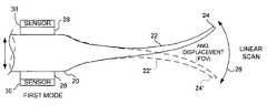
- FIGS. 1A and 1Bare schematic diagrams that respectively illustrate a FOV of the tip of an optical fiber scanner that is angularly displaced, and an optical fiber that is moved in a circular scanning pattern in accord with the present invention
- FIG. 1Cis an isometric schematic view of a part of a tube piezoelectric actuator driving a tapered optical in a variable radius or spiral scan;
- FIG. 1Dis a schematic illustration of a propeller scan mode of a tapered optical fiber in accord with the present invention.
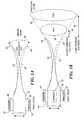
- FIGS. 2A and 2Bare schematic views of an optical fiber tapered along its longitudinal axis, and of an optical fiber having a modulated taper, with a hinged tip;
- FIG. 2Cillustrates the dual resonance motion of the tapered portion of the optical fiber and the distal end of the optical fiber that are coupled through a hinge portion
- FIG. 3illustrates the optical fiber of FIG. 2B , showing the motion of the tip along its longitudinal axis
- FIG. 4(Color Photo) is an enlarged photo of a micro-fabricated fiber having a tapered geometry of 0.12 mm at its right base and 0.01 mm at its tip, which is moving linearly, with ⁇ 80° FOV, at about a 40 kHz frequency;
- FIG. 5(Color Photo) is a close-up photo highlighting the vibratory node and the light emission from the optical fiber of FIG. 4 ;
- FIG. 6(Color Photo) is a photo showing another fiber scanner having a tip moving in a 2D space filling pattern (with ⁇ 180° vertical movement);
- FIG. 7is a schematic view of a micro-fiber scanner with a 0.25 mm lens at the scanning fiber tip and a 2.0 mm diameter scan lens for generating high resolution images, acquiring images, or sensing light from a surface;
- FIG. 8(Color Photo) is a photo showing a 0.125 mm diameter fiber scanner tip having an epoxy micro-lens fabricated on the tip;
- FIG. 9(Color Photo) illustrates the linear scan line displayed on a screen using the optical fiber scanner of FIGS. 1A , 1 B, and 2 A or 2 B;
- FIGS. 10A and 10Bare schematic cross-sectional views showing a fiber scanner with two different lens arrangements on the micro-machined fiber optic tip;
- FIGS. 11A and 11Bare schematic views respectively showing a waveguide tip moving in a rounded arc pattern with only lateral actuation, and in a flattened arc pattern with both lateral and synchronized axial actuation;
- FIGS. 12A and 12Brespectively show a round cross-section of a first tapered optical fiber and an elliptical cross-section
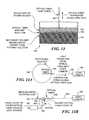
- FIG. 13is an elevational schematic diagram of a container that includes multiple layers of solutions, for producing a hinge section on a tapered optical fiber;
- FIGS. 14A and 14Bare schematic plan and elevational views of apparatus used for producing a micro-lens on a tapered optical fiber
- FIGS. 15A , 15 B, and 15 Crespectively illustrate a micro-lens formed without applying an external force and micro-lenses formed by apply external forces distally and proximally of the end of the optical fiber;
- FIG. 16is an isometric schematic diagram of a system for forming a micro-lens using a laser to heat the distal tip of a tapered optical fiber;
- FIG. 17is an isometric schematic diagram similar to that of FIG. 16 , illustrating an alternative approach for applying a force along a longitudinal axis of the optical fiber while forming the micro-lens;
- FIG. 18is a schematic block diagram of a display system employing the present invention.
- FIG. 19is a schematic block diagram of an imaging system employing the present invention.
- FIGS. 20A and 20Bare respectively a side elevational view of a mechanical structure having a tapered tip that is caused to scan, and a greatly enlarged isometric view of the distal end of the mechanical structure of FIG. 20A , showing an integrated light source on the distal end.
- a waveguide 20is typically formed in a fixed-free cantilever configuration, with a distal (free) tip 24 swinging at a near resonant amplitude from an extreme displacement in one direction as shown by the solid lines in FIGS. 1A and 1B , to an extreme displacement in an opposite direction as shown by the dash lines and as indicated by the prime reference numbers (e.g., distal tip 24 ′).
- Arc 26is proportional to the optical FOV for the linear scan.
- a micro-fabricated region 22 of waveguide 20is typically 0.50 to 2.0 mm in length, with a cross-sectional diameter nonlinearly tapering from about 0.1 to 0.01 mm (as shown most clearly in FIG. 2 A).
- the tapered geometrycan be fabricated nonuniformly for special scanning features (see light guide 50 in FIGS. 2B , 2 C, and 3 ).
- an optical fibercan be formed that is axially asymmetrical, to achieve different scanning parameters about different axes.
- Optical fibers with a round cross-section 150 as shown in FIG. 12Awill have substantially the same resonance characteristics about any two orthogonal axes extending through the cross-section.
- optical fibers having an elliptical cross-section 152 as shown in FIG. 12Bwill have different resonant frequencies about two orthogonal axes aligned with the major and minor axes of the elliptical cross-section, since there will be greater resistance to flexing about the minor axis than about the major axis.
- the scanning micro-fabricated waveguidehas a much smaller mass, inertia, and viscous drag than a scanning MEMS mirror that is 1 mm square (not shown). Furthermore, the optical surface of the waveguide is typically less than 10 microns in diameter (at the distal tip), versus MEMS mirror sizes that are at least 50 to 100 times larger. Due to the smaller size of the optical surface on a resonant scanning waveguide relative to the planar mirror surface of resonant mirror scanners, the deterioration of the optical surface is expected to be slower, and the lifetime of the waveguide scanner in accord with the present invention is expected to be longer.
- the geometry of the resonant waveguide scanneris preferably cylindrical, which is an ideal aspect ratio for mounting within spectacle frames for micro-displays and within slender tubes for micro-image acquisition systems (endoscopes and borescopes).
- Prototype optical fiber scan systemsare expected to be no greater than 2 mm in diameter, which is the diameter of a scan lens 72 shown in FIG. 7 and of imaging lenses 112 and 114 shown in FIGS. 10A and 10B .
- the resonant waveguide optical scanneris extremely low cost in both fabrication and material unit costs.
- the multiple actuators that drive a mirror-based systemare complex in design and fabrication, while only a single, inexpensive actuator is needed to drive a scanning optical fiber waveguide into its resonant scanning patterns.
- a mirror scannerhas the disadvantage of requiring optical alignment with the illuminating light source or optical fiber, while a scanning waveguide can be micro-fabricated at the end of an optical fiber. Additional optical coupling and alignment are unnecessary.
- a micro-fabricated waveguide scannercan be modified to include an integrated micro-optical lens for specific optical scanning applications.
- high-resolution optical scanningmay be achieved with a micro-lens 118 attached directly to the distal end of the waveguide scanner, as shown in FIG. 10B.
- a micro-lens made from ultraviolet-(UV) cured optical adhesive (epoxy)can be fabricated and firmly attached to the tip of the scanning waveguide.
- FIG. 7schematically illustrates a 0.25 mm micro-lens (a ball lens 70 ) and shows light rays 76 emitted through this ball lens focused by imaging lens 72 onto a surface 74 .
- micro-lensformed from spinning a droplet of UV-cured (or heat cured) optical adhesive, for example, an epoxy or other polymer, attached to an optical fiber are shown in FIG. 8 , and are shown as drops on a glass slide in FIG. 9 .
- the micro-lensboth collimates the emerging optical beam and adds mass to the distal tip. At modes of resonance greater than the fundamental, the added mass moves the vibratory node very close to the distal tip of the optical fiber waveguide. The vibratory node then acts as an effective point source of light that is simply rotated by the angular deflection of the micro-lens.
- the vibratory node achieved with the micro-lensis similar to that provided by a micro-fabricated “hinge” section 54 shown on nonlinear tapered optical fiber light guide 50 in FIGS. 2B , 2 C, and 3 , for use in both linear and 2D scan patterns.
- a proximal nonlinear tapered portion 52is reduced in cross-sectional diameter toward the distal end, but is necked-down to a substantially smaller diameter at hinge section 54 .
- a distal nonlinear tapered portion 56first increases in diameter and then continues to decrease in size along a nonlinear taper toward a relatively small diameter distal tip 58 .
- the hinged sectionincreases angular and positional displacement of the tip when the optical fiber is driven by an actuator. If the section near the tip is kept significantly more rigid than the hinge region, then the relationship between tip angle (and thus, the exit angle of light from the distal tip of the optical fiber) and drive function is maintained in a linear relationship.
- the light emitted from the distal tip of the optical fiberalso appears to come from a fixed point (i.e., from a fixed “optical node”), which simplifies external lens design—if such lenses are used.
- Hinge section 54can be formed using the technique schematically illustrated in FIG. 13 , which provides for etching an optical fiber light guide 162 in a container 160 holding multiple layers of solutions. These solutions include a top layer 164 of iso-octane or other solvent, a middle layer 166 of a suitable optical fiber etchant solution, and a bottom layer 168 of a secondary solvent.
- the uppermost and lowermost solution layersare thus both organic solvents or other non-etchant solutions that are not miscible with the etchant solution.
- the density of the uppermost solvent layermust be less than that of the etchant solution, while the density of the lowermost secondary solvent layer must be greater than that of the etchant solution. As shown in FIG.
- the immersed fibercan be etched to create the hinge section or other desired profile shape, in which the cross-sectional diameter can increase and decrease selectively along the optical fiber longitudinal axis.
- the optical fibercan be immersed in baths that contain gradients of pH, acid concentration, or solute diffusion coefficients.
- the etching processcan be optionally influenced by confining the waveguide in a tube or other physical barrier that affects the etching rates axially and laterally along the waveguide.
- the method of etchingcan be modified to include flowing liquid acids or other solvents or vapors or abrasives that may vary in concentration or flow rate during the etching process.
- the optical fibercan be coated with a layer that may be a graded or predetermined pattern of protection from etching, such as a layer of photoresist that has been exposed differentially to polymerization.
- the above techniquescan thus be used to produce an optical fiber having two or more distinct sections of differing radii, so that each section has an independently determinable length.
- the resulting optical fibercan be made to have two or more distinct resonances.
- separate resonancescan be created for raster scanning, where one resonance corresponds to a horizontal scan rate, and another different resonance corresponds to a vertical scan rate.
- FIG. 3illustrates a node 64 that is developed relative to a fixed reference 60 , as the light guide is driven toward a resonant condition by an actuator (not shown).
- Arcs 62 and 62 ′are apparent in the proximal nonlinear portion of the light guide, while the distal tip moves in an arc between extremes 66 and 66 ′.
- FIG. 2Cillustrates that different resonant frequencies can be developed for proximal nonlinear tapered portion 52 and for distal nonlinear tapered portion 56 , as each portion describes arcs 62 and 62 ′, respectively.
- Jacobsonhas described and claimed an oscillating and resonant scanning optical fiber with a modulated light source at the proximal end with synchronized actuators at the distal end to project an image as a visual display.
- Jacobsondoes not disclose any micro-optical fabrication of micro-lenses or electronic feedback control strategies like those used in the present invention.
- the prior artdiscloses an optical fiber that is linearly tapered, and only used within a near-field scanning optical microscope.
- image acquisition using resonant scanning of an optical fiberis disclosed in regards to medical applications of the present invention; however, it must be emphasized that the present invention is not limited to such applications.
- the initial fabrication method used to taper commercial optical fibersis based on heating the silica glass and pulling it to taper and eventually break the optical fiber at roughly 5 to 20 microns in tip diameter.
- the “fiber puller”is a commercial quartz pipette puller (available as Model P-2000 from Sutter Instrument Co.) with special holders for optical fibers having 0.125 mm cladding diameter.
- the optical fiber pulleruses a CO 2 laser emission to heat the optical fiber quickly and uniformly, while forceful pulling occurs at a pre-programmed time after the silica fiber softens and starts to yield under low tensile stress (gravity).
- This programemploys only a single pulling step that generates the general tapered profile; however, much more complex shapes can be generated by using a multi-step pulling process.
- the plastic bufferis removed by mechanically stripping and wiping away residual plastic debris.
- the remainder of the optical fiber(extending as approximately a 1 meter “pigtail”) retains its plastic buffering and is connected to an optical light source (typically one or more lasers) via an optical fiber coupling mechanism (e.g., an Ultrasplice, from ACA Inc.).
- the heating and pulling method employed for micro-fabrication of tapered waveguideshas been applied in the prior art to silica, single-mode optical fibers for the purpose of making probes for near-field scanning optical microscopes.
- the general methodcan be applied to non-silica glass fibers, hollow fibers, and non-glass optical fibers, such as plastic fibers using radiant heating.
- the advantages of this pulling methodis that it has been well established for fabricating tapered optical fibers for scanning probe optical microscopes.
- the tapered tip of the waveguidecan be made much smaller (less than about 5 microns) than the core diameter of the optical fiber, generating a smaller point source of light.
- the reduction in source sizecan increase the spatial resolution of the scanned light projection display or in applications of optical sensing or image acquisition.
- the sides of the tapered waveguideare coated with a reflecting material such as aluminum to prevent light from leaking out the sides before reaching the distal tip.
- a second alternative fabrication methoduses acid etching and/or mechanical polishing of the silica or glass optical fiber or waveguide.
- the waveguideis tapered by first removing material from the radial extremity.
- the waveguide corecan be preserved, while still providing the degree of tapering necessary for the specifications of high scan amplitudes and frequencies required.
- the most common method for tapering silica and glass optical fibersis acid etching, typically with an aqueous solution of hydrofluoric (HF) acid.
- HFhydrofluoric
- the most straightforward technique for controlling the tapered profileis by immersing the distal end of an optical fiber (protective plastic buffering removed) in HF acid and slowly withdrawing the optical fiber at a pre-programmed rate.
- the methods for reproducibly tapering optical fibershas been developed in the prior art by users of scanning probe optical microscopes.
- both the tapered profile and performance requirements for the scanned probe microscopesi.e., short conical tapers
- are very different from those of micro-fabricated fiber scannersi.e., exponentially decreasing tapers. Additional procedures for the micro-fabrication of tapered waveguides and optical fibers are described herein.
- the surface of the uniform tapered geometrycan be smoothed by polishing or modified into an axially asymmetric profile (see FIG. 12 B).
- Micro-beveling devicescan be used to polish the distal tip, trim the tapered profile, and optionally, to reduce the structural rigidity at discrete points, such as adding hinge section 54 , as shown in FIGS. 2B , 2 C, and 3 .
- Micro-beveling and micro-polishing devicesare commercially available and recently have been used to trim sub-micron-sized tips of tapered optical probes for scanned optical microscopes.
- the micro-fabricated waveguidecan be used in a scanning system in which it is vibrated at one or more frequencies by an actuator. If one of these frequencies corresponds to a mechanical resonance of the waveguide, then an amplification of the waveguide motion ensues.
- a tapered optical fiberwas rigidly attached to piezoelectric bimorph benders 28 (see FIGS. 1A , 1 B, 2 A, and 2 B) or a piezo tube 36 (see FIG. 1C ) with quadrant electrodes by either gluing or mechanically clamping.
- a tapered portion 108 of an optical fiber 106is attached to the distal end of a piezoelectric actuator 102 , close to the proximal end of the taper, as shown in FIGS. 10A and 10B .
- the exact point of attachment, mechanical properties of the waveguide, and taper geometrydetermine the resonance frequencies of the optical fiber scanner.
- the actuation amplitude and frequency of the piezoelectric actuatordetermine the amplitudes of optical fiber displacement and deflection of a distal tip 110 (shown in FIGS. 10 A and 10 B), its frequency, and the optical scanning pattern it describes.
- an optical fiber cantileveris extended from about 1 to about 4 mm out from its point of attachment at the end of the piezoelectric bimorph to achieve high FOV scanning frequencies of greater than 20 kHz.
- the opposite end of the piezoelectric actuatoris held fixed (e.g., epoxied to the end of a steel tube 100 ).
- a protective tube 104surrounds the optical fiber and the actuator.
- piezoelectric electrodes(not shown in FIG. 10A or 10 B) on the actuator are connected by fine wires (also not shown) to an electronic function generator included in control 40 (shown in FIG. 11A ) that can produce a sinusoidal waveform of variable voltage (amplitude) at a desired frequency (adjustable from about 1 kHz to about 100 kHz).
- the actuatorcan be shaped to have a mechanical resonance that is close in frequency to that of micro-fabricated light guide 50 .
- Separate imaging and/or scan lenses 112 and 114can be disposed adjacent to the tip of the micro-fabricated fiber scanner to generate focused linear and 2D scan patterns onto a screen, as shown in FIG. 9 , and FIGS. 10A and 10B . Furthermore, a micro-lens 118 can be fabricated onto distal tip 110 of optical fiber 106 , as shown in FIG. 10B. A photograph of such a micro-lens is reproduced in FIG. 8 .
- the micro-lenscan be formed on the micro-fabricated optical fiber cantilever by the following procedure, which is schematically illustrated in FIGS. 14A and 14B .
- the lens materialis a UV-cured optical adhesive administered to a separate substrate ( FIG. 9 ) or to an optical fiber waveguide (FIG. 8 ).
- the added fabrication step of attaching a micro-lens at waveguide distal tip 110helps to simplify the secondary lens system (imaging and/or scan lenses 112 and 114 ).
- the micro-lens formed at the distal tip of an optical fibercan be shaped by the centrifugal forces resulting from spinning an optical fiber 182 in a circular movement on a mass-balanced rotating disk 180 , as shown in FIGS. 14A and 14B .
- important factorsare the optical fiber waveguide distal tip geometry and surface adhesion properties (hydrophobicity), viscosity, cured refractive index and shrinkage, and surface tension (adhesion) of the optical adhesive, which can be varied to produce micro-lenses of desired opto-mechanical properties.
- An electric motor 190rotates disk 180 , which includes an optical fiber rotary joint 188 at its center.
- the optical fiberis mounted on the rotating disk with its tapered end facing radially outward.
- a small drop of optical adhesive(too small to be seen in the figures) is admitted manually with a micropipette to the tapered portion near the optical fiber tip. Inspection of the droplet is done under 80 ⁇ magnification, while the optical fiber pigtail is coupled to a laser diode or other light source 194 through an optical fiber 192 , illuminating the tapered tip and droplet of optical adhesive with light 184 that is emitted from the distal tip of optical fiber 182 .
- Motor 190is started, causing the disk to rotate, and real-time evaluation of the collimated and/or focusing light emission from the droplet of optical adhesive is monitored with a video camera 186 .
- a strobe light(not shown) is synchronized with the rotating disk so that the profile of the droplet shape may be checked during spinning.
- a UV lamp(not shown) is turned on to cure the optical adhesive droplet.
- the process of UV-curing and hardening the micro-lenscan be controlled while monitoring the optical beam profile as the micro-fabricated optical fiber is spinning.
- the entire apparatusmay be placed in a vacuum chamber to reduce frictional forces due to air drag that tend to asymmetrically distort the shape of the lens.
- the distal tip of an optical fiber 220is positioned within a focused beam path 226 of a high power laser light source 224 (e.g., a Synrad Inc. 25 W laser with 370 mm focal length lens).
- the optical fiber material(silica glass) is heated locally with the coherent light from the laser to a sufficiently high temperatures to melt, achieving a low viscosity state. At this point, the molten glass forms a droplet 228 .
- the shape of droplet 228is primarily determined by surface tension forces and the viscosity of the molten glass.
- the optical fiberis oriented vertically so that the force due to gravity does not distort the lens shape in an asymmetrical manner.
- Monitors 234 and 238are used with optional lenses (not shown) to measure the beam spot shape and size.
- Multiple point measurements along beam paths 232 and 236are made with the monitors by employing a beam splitter 230 to sample beam spot size and shape at two distances from the optical fiber distal tip, enabling more accurate estimation of the divergence/convergence angle of the light exiting the micro-lens comprising droplet 228 .
- a second method for shaping the micro-lens to achieve desired optical characteristicsuses an air flow in a directed manner to apply a force to the lens material while it remains in a low-viscosity state. This force is preferably applied uniformly and symmetrically about the axis of the optical fiber.
- the air temperature surrounding the optical fibermay be controlled so that the air does not cause significant changes in the desired viscosity of the lens during the lens formation process.
- the required forcecan be applied by moving optical fiber 220 along its axis during lens formation.
- a longitudinal displacement driver 240can be employed to accelerate the fiber axially.
- high power laser light source 224is pulsed to strike the distal tip of the optical fiber, again forming droplet 228 by melting the glass comprising the optical fiber.
- the glassremains in a molten state for a short time period, during which the axial acceleration force causes reshaping of the lens.
- This method for lens shaping using the laser-induced melting of the fiberis preferred, since it readily enables a feedback control scheme to be employed in controlling the optical parameters of the micro-lens that is being formed.
- FIGS. 15A , 15 B, and 15 Crespectively show an optical fiber 200 on which a micro-lens 202 is formed without applying any force, a micro-lens 204 formed while applying a distally directed force, and a micro-lens 206 formed by applying a proximally directed force.
- the direction of the forcecan be controlled by varying the manner in which the optical fiber is mounted on the rotating disk (to vary the direction of centrifugal force acting on the droplet comprising the micro-lens), and the magnitude of the force can be controlled by varying the rotational speed of the disk.
- the current applied to the longitudinal displacement drivercan be controlled to vary the direction and amplitude of the force.
- Sensors to detect the relative position of the waveguideare incorporated in a post waveguide and micro-lens fabrication step.
- One embodimentuses electromechanical sensors, such as thin-film, flexible piezoelectric films on the sides of the scanning waveguide. As the sides of the waveguide bend, the individual sensors undergo cycles of either tensile or compressive stress, producing either positive or negative voltage output signals.
- piezoelectric sensorscan be deposited onto the side of the waveguide by adhering thin piezoelectric films or by conventional thin-film deposition techniques, using masking, etching, or cutting to generate sensors on each of the four quadrants or sides of the waveguide.
- FIGS. 1A , 1 B, 2 A, and 2 Bschematically illustrate sensors 30 overlying piezoelectric bimorph actuators 28 , but it will be appreciated that the sensors are mounted separately from the actuators.
- the piezoelectric bimorph actuators and the sensorsare coupled to a control 40 by leads 42 .
- a second embodimentemploys an optical source producing radiation at a wavelength not being used for the scanner application (e.g., infrared (IR) lasers or light emitting diodes (LEDs)) and matching IR detectors (IR photodiodes) to monitor the direction of the scanning waveguide.
- Sensors 30 in FIGS. 1A , 1 B, 2 A, and 2 Bcorrespond to these optical sensors in this embodiment. Details of exemplary sensors suitable for this purpose are disclosed in the priority parent patent application referenced above.
- Both the light sources and detectorsare preferably made from diode material that can be positioned at either the distal or proximal end or the micro-fabricated fiber scanner.
- the diodeswill send and receive light to and from the distal tip using optical fibers running with the scanning optical waveguide. If disposed instead at the distal end, then the diodes may be positioned to detect an IR beam (or other waveband of light that is being used) as it reflects from the scanning waveguide or to detect its shadow in transmission. Since the motion of the waveguide is directly related to the motion of the IR beam, the optical detectors will be spatially arranged to detect differential amounts of light depending on the disposition of the IR beam. This optical detection method is routinely used to measure the relative motion of vibrating waveguides within scanning probe microscopes. In both embodiments, differential signals from the multiple sensors (piezoelectric thin films attached to the sides of the waveguide or optical detectors attached to the inside walls of the waveguide enclosure) will be used to determine the real-time position of the scanned waveguide.
- an optical scanner micro-fabricated from a tapered optical fiber waveguideis similar to an optical scanner based on a mirror, in that the position of the resulting optical beam is a direct function of the position over time of the moving tapered fiber or mirror.
- the connection and alignment with the optical source or illuminating optical fibersis a simple and robust fiber-to-fiber connection in the present invention, resulting in more than about 90 percent coupling efficiency.
- mirror-based optical scannersmust have packaging that can maintain alignment and precise dimensional stability of a more complex optical system of an optical fiber holder and lenses and also have the problems of multiple reflections and stray light.
- a piezoelectric bimorph and a tube actuatorcan accomplish the same function, in the present invention.
- the base of the micro-fabricated cantilever waveguideis moved.
- the bimorphis a 1D actuator and the tube is a 2D or three-dimensional (3D) actuator
- two piezoelectric bimorph actuators 28can be assembled to create 2D actuation, as shown in FIGS. 1B , 2 A, and 2 B.
- Two-dimensional actuationcan produce resonant or non-resonant linear motion in two dimensions, and in several scanning patterns, including: a linear scan 26 (used in a rectilinear or raster pattern) as shown in FIG.
- 1Aa FOV 32 that is in a circular pattern 32 or spiral pattern 37 as shown in FIGS. 1B and 1C , respectively; a rotating linear or propeller scan pattern 38 as shown in FIG. 1D ; and other Lissajous patterns (not specifically shown, but readily derived by applying an appropriate drive signal to actuator 36 in FIG. 1 C).
- 1D actuationcan produce well-defined 2D patterns and also space-filling scanning motions (e.g., beating or chaotic motion), as shown in FIG. 6 .
- FIG. 18schematically illustrates an exemplary scanning optical fiber display system 250 in accord with the present invention.
- an intensity data source 252such as a video signal from a computer or other video source, is supplied through a lead 256 as a modulated input signal to a modulatable light source 254 .
- the 2D position of the scanned spot or scannercan be measured and the desired pixel brightness at that location found by accessing a look-up table.
- the light sourceprovides modulated light that is input to the proximal end of a scanning optical fiber 258 , which is driven in desired scanning pattern.
- the scandoes not need to be a periodic or repeatable scan. As long as the scan is space-filling within the duration of a frame, a complete coherent image will be formed.
- the modulated light emitted from the distal end of the scanning optical fiberis directed along a path 264 to a display screen 260 (or directly into a user's eye and onto the retina of the eye (not shown)).
- the scanning optical fiberscans the modulated light across the display screen or eye of the user, producing an array of modulated intensity light spots 262 (or pixels), each spot having an intensity as determined by the modulated input signal. Accordingly, an image is formed comprising the light spots 262 .
- one or more lenses 266can be provided to ensure that the light emitted from the distal tip of the scanning optical fiber is directed and focused on each point in the array.
- a separate light sourcecan be included for each of a plurality of different colored modulatable light sources (e.g., red, green, and blue lasers), so that a color image can be created by combining the modulated light from the three different color sources to produce each light spot.
- the output optical beams from the three light sourcescan be coupled into a single optical fiber or into separate optical fibers that are optically combined before being connected to the optical fiber pigtail of the micro-fabricated fiber scanner.
- each pixelTo display a scanned optical image consisting of a 2D array of pixels, each pixel must have a specific location, which relates to the position and orientation of the micro-fabricated fiber scanner. At each pixel location, the optical intensity value must be re-displayed at the refresh rate, typically 60 Hz to avoid a noticeable flicker. Thus, within ⁇ fraction (1/60) ⁇ second, the optical fiber scanner must move through every pixel location in the 2D image.
- the 2D scan patterncan be generated and refreshed at 60 Hz in one of several ways.
- a high-frequency linear scancan be swept back and forth at 30 Hz, or a circular scan line can be enlarged and constricted repeatedly in a spiral at 30 Hz, or a high frequency linear scan can be rotated like a propeller blade.
- a sVGA display of 800 ⁇ 600 pixelswill require a 20 kHz bidirectional line scan that can be swept back and forth at 30 to 60 Hz.
- FIG. 19schematically illustrates an exemplary 2D scanning optical fiber image acquisition system 300 employing the present invention.
- a tapered scanning optical fiber 302is caused to move relative to the two orthogonal directions indicated in the figure to scan a surface 306 .
- surface 306need not be planar, but instead, can be irregular or curved.
- a coupled light source 304 at the proximal end of the tapered scanning optical fiberprovides light that is conveyed through the optical fiber and emitted from the distal tip of the optical fiber so that the light travels along a path 310 and strikes surface 306 at a point 308 .
- FIG. 19is a very simplistic illustration and that many variations of this technique can employ the present invention to carry out related functions.
- surface 306might comprise a barcode that is scanned with an optical fiber actuated to scan in only a single dimension.
- a waveband of the light source used to image the surfacecan be selected to detect specific characteristics of the surface being scanned.
- the light sourceis not electronically modulated to create sampled or pixilated images.
- the illuminated objecthas sufficient optical contrast (variable absorption, scattering, and topography) to modulate the backscattered and reflected light.
- additional photon detectorsare required to measure and temporally record the optical signal, which is synchronized with the waveguide position and displayed and/or stored accordingly.
- the samples (or pixels)must be recorded to (or output from) a buffer synchronized to the scanned light spot location or equivalently, to the scanner (optical fiber tip and/or mirror) position.
- a buffersynchronized to the scanned light spot location or equivalently, to the scanner (optical fiber tip and/or mirror) position.
- the 2D position of the scanned spot or scannercan be measured at the same moment the intensity of the back scattered light is measured with a photo detector.
- a time record of the position and intensitycan be kept for each pixel.
- an imagecan be formed by taking the record of the position and intensity acquired for all the pixels that produce an image frame (an intensity map image).
- the scan in an image acquisition systemdoes not need to be periodic or repeatable. As long as the scan is space-filling within the duration of a frame, a complete coherent image will be captured.
- the present inventioncan also be applied to a tapered cantilevered structure 350 having a tapered portion 352 that is reduced in diameter to a distal end 356 .
- This embodimentis usable for image display on a surface (or in a user's eye), or for image acquisition in conjunction with one or more photodetectors (not shown).
- structure 350need not be made of a material that is able to convey light or other electromagnetic energy, i.e., the structure need not be a waveguide for electromagnetic energy.
- An actuator 354is energized to apply a driving force to structure 350 , causing distal end 356 of the structure to scan in a desired pattern, e.g., as described above.
- a control and power supply 362provides electrical current to actuator 354 through leads 364 , which extend along the longitudinal axis of structure 350 , and controls the actuator so as to achieve the desired pattern of scanning.
- a light source 358Integrally disposed (or otherwise attached) to a distal face 360 at distal end 356 of structure 350 is a light source 358 .
- a LED or other suitable light sourceenergized with an electrical current that is also provided through leads 364 can be employed for this purpose.
- This light sourceemits light as the distal end moves in the desired scan pattern. The emitted light can be directed onto a surface (not shown) to illuminate the surface with the light in the desired pattern.
- other devicessuch as a light sensor, might instead be integrally included or attached to distal face 360 , where it is desirable to use the scanning structure to move the device relative to some surface or other object.
- the driver amplitudeis reduced to decrease the FOV. Due to nonlinear effects, the phase relation between the drive and the output is not constant. If not accounted for, either by manual adjustment or by a look-up table, the image will become incoherent. Environmental changes may cause the resonant frequency of the optical fiber to change, also resulting in a phase and amplitude shift. These shifts would have to be compensated by changing the amplitude and phase of the drive signals manually.
- phase-locked loopPLL
- the PLLwill use measurements related to the scanner or scan spot position, for example, monitoring the electric current through the piezoelectric tube, or direct measurement of the spot position.
- the PLLcompares these measurements with the phase of a reference waveform, and adjusts the scanners drive signals so that the phase between the reference and the waveform from the sensor stay locked to each other regardless of changes due to internal dynamics or mechanics or external environmental effects.
- the amplitude of the scancan be kept at a desired level (or possibly time-varying) by using an auto-gain control to keep the amplitude of a related periodic measurement from the scanner or scan spot position at the desired level.
- the PLL controllershould have an additional PID amplitude control.
- An amplitude demodulatorcan be provided to determine the modulation envelope magnitude, and the additional PID amplitude control maintain a constant level for the envelope magnitude by adjusting an amplitude of the output signal from a voltage controlled oscillator (VCO) used to produce it (none of these components are shown).
- VCOvoltage controlled oscillator
- the PLLcan either change the frequency until the scanner response matches the phase, or can directly change the phase, keeping the frequency constant.
- the first approachwhich involves changing the drive frequency until the response phase matches the reference phase, is useful for maintaining the scanner at the frequency of maximum displacement (e.g., resonance, which has a phase difference from input to output of 90°, in linear vibration theory) regardless of environmental changes or manufacturing variability. Because the drive frequency changes, the scanner determines how often a sample will be acquired or a pixel displayed. Therefore, the scanner becomes the master and the acquisition or display system becomes the slave.
- the frequencyis constant, but the phase of the driver changes until the phase of the output matches that of the reference.
- the acquisition or display systemis the master, and the scanner is the slave.
- the amplitude and phase of the scanner outputcan be determined using a lock-in amplifier or sine wave parameter identification.
- a linear feedback loopadjusts the amplitude and phase of the sinusoidal drive signals to match the desired amplitude and phase.
- the frequency of the sinusoidal scanis the same frequency as the drive signal and the same frequency used in the lock-in amplifier.
- the scanneris the slave, and the acquisition or display system is the master.
- a robust nonlinear control scheme for asymptotic trackingcan be used to force the scan position (measured by the aforementioned sensors) to follow a reference waveform regardless of manufacturing variability or environmental changes.
- Asymptotic trackingmeans that the response of the scanner (including its shape, phase and amplitude) will match the reference (and its shape, phase and amplitude).
- nonlinear control algorithmscan compensate for undesirable dynamic effects.
- linear or nonlinear system identificationcan determine parameters of the dynamic model such as the resonant frequency, allowing for such features as resonant frequency tracking (that is tracking of frequency of maximum amplitude) and adaptive control.
- a nonlinear control scheme for asymptotic trackingcan be used for the following scans, 1D and 2D, in the following three scan systems:
- Trackingallows the creation of stable coherent images, regardless of differences between scanner actuator and optical fiber due to manufacturing variability, and within the same scanner actuator and optical fiber, due to environmental changes. Tracking also allows the FOV to be changed, resulting in a zooming feature. In open loop, changing the FOV also changes the phase.
- Whirlis a nonlinear cross-plane instability. If the optical fiber is driven in the horizontal direction only, the instability vertically causes the optical fiber to vibrate both vertically and horizontally, forming ovals or rotated lines. Because the horizontal scan is not purely horizontal, including a vertical scanner does not produce a raster scan, but instead, produces a complex Lissajous pattern. If a raster scan is assumed, but not produced, then the image is either distorted or incoherent. Analysis of the dynamic models of the optical fiber scanning system when applied via a robust state space controller with feedback linearization show that 1D tracking also removes whirl. Because the axes are cross-coupled, whirl (motion in the non-driven direction—vertical) decreases the amplitude in the driven direction—horizontal. When whirl is removed, the horizontal amplitude will increase.
- the horizontal scanis periodic, there will be portions of the scan going left to right, then others right to left. If the acquisition (or display) is sequential, alternate lines will be flipped, resulting in an incoherent image. Every other line could be discarded, but this approach would result in a lower vertical resolution. Alternatively, every other line could be flipped and re-interleaved computationally in the buffer, resulting in a coherent image of the same resolution as sampled.
- the phase of the scanner to the referenceis important when re-interleaving, and if phase is not correctly maintained, the alternate lines will not match up. However, the phase may change due to environmental effects or changes in drive amplitude (for zooming).
- the sampling or output ratecan be adjusted electronically to account for nonlinear scans. For instance, most resonant scans are sinusoidal, resulting in barrel distortions due to the nonlinear scan speed, but regular sampling rates. In this case, the distortion is known to be sinusoidal, so the barrel distortion can be eliminated computationally in the image buffer. Alternatively, the application of variable sampling rates will also remove the distortion.
- Trackingmatches the scanner output shape, phase, amplitude, and frequency to a reference waveform. This technique simplifies acquisition, because the 2D position of the spot at each moment in time can be assumed, and the appropriate pixel recorded or displayed.
- the reference waveformsare horizontal and vertical sinusoids of the same frequency, but 90° out of phase; the amplitude of these waveforms has a sawtooth envelope, with a frequency one-fourth the frame rate.
- Tracking controlcauses the output to follow this reference. This step removes the deleterious effects of low damping (such as ringing and undesired toroidal scanning at high frame rates), which other techniques (open loop, PLL, etc.) cannot control. Tracking also accounts for amplitude dependant changes in phase, which occur every frame.
- the reference waveformsare horizontal and vertical sine waves of the same frequency, but in-phase.
- the horizontal sine wave amplitudeis varied sinusoidally at a frequency equivalent to one-quarter of the frame rate
- the vertical sine wave amplitudeis varied co-sinusoidally, again at a frequency equal to one-quarter of the frame rate.
- Tracking controlcauses the output to follow this reference. This technique will also remove the whirl, which makes the “propeller” look like a rotating oval instead of a rotating straight line.
- the sawtooth envelopeexpands, contracts, expands, and contracts the sinusoid amplitude in each period.
- the relative phasesare 0°, 0°, 180°, and 180°.
- an adjustmentis made for these differences in apparent order of samples to achieve four frames per scan period. That is, with the first expansion being the reference, the first contraction is flipped upside down, the second expansion is flipped right-to-left, and the second contraction is flipped upside down and right-to-left.
- a 2D scancan be produced using a 1D actuator by taking advantage of the nonlinear whirl.
- Whirlcauses an oval shaped scan from forced vibrations in only one axis.
- the amplitude envelope of the sinusoidal drive signalcan be modulated in a sawtooth pattern similar to the propeller scan.
- the whirlwill contract and expand with the sawtooth envelope.
- the phase and amplitude of the whirlare not controllable in open loop. It is therefore preferable to use feedback control to control the phase and amplitude of the whirl.
- the whirl amplitudecan be controlled by adding a dither signal to the drive signal in the single axis of actuation, e.g., x-axis.
- the dither signalis high frequency, and it does not affect the x-axis scanner response because of the low pass nature of the x-axis dynamics.
- the y-axis scanner responseis affected through the nonlinear cross coupling of the two axes.
- a relationship between the drive signal u, and the vertical (non-driven) axis ycan be found.
- the drive signalcan be shaped such that there are linear tracking error dynamics.
- Standard linear regulation schemessuch as state space techniques
- nonlinear regulation schemescan be used to drive the tracking error to zero.
- nonlinear tracking schemessliding mode control
- Robustness of the error dynamics regulation or the tracking schemesmakes the scan insensitive to model parameter inaccuracies or changes (e.g., temperature) and to higher modes or other dynamics not included in the dynamic model.
- the first methodcontrols a 1D actuator to produce 1D scan patterns.
- the second methodcontrols two actuators used to produce 2D scan patterns.
- the third methodcontrols a single actuator to produce a nonlinear 2D scan pattern. All three methods are employed to maintain a well-defined 2D pattern of motion of the waveguide at a specified frequency of operation. Due to the nonlinearity of the micro-fabricated scanner, these three methods are superior in performance to methods that require linear systems and do not keep frequency constant, such as those that employ PLLs.
- a final control methodis proposed to reduce the radius of curvature of the arc formed when the waveguide scans in 2D.
- the curvature of an arc 138can be reduced to that of an arc 146 , as illustrated in FIGS. 11A and 11B , respectively.
- a waveguide 130is excited into near resonance by a piezoelectric bimorph actuator 132 , causing a tapered portion 134 of the waveguide to bend as a distal tip 136 moves through arc 138 .
- Control 40provides the driving current to the piezoelectric bimorph actuator through leads 42 .
- an axial actuator 142is added and controlled by current supplied through a lead 144 .
- Axial actuatorcauses the waveguide to move back and forth along its longitudinal axis relative to a reference 60 , in synchrony with the movement of the distal tip of the waveguide, so that as the waveguide reaches an end of arc 146 , the waveguide is moved distally an amount ⁇ D, which is sufficient to compensate for the movement of the distal tip away from a plane that is orthogonal to the longitudinal axis and extends through the center of arc 146 .
- the same axial correctionis applied at the opposite end of arc 146 .
- the axial transducerwill have moved the waveguide proximally along the longitudinal axis of the waveguide, relative to its position at the ends of the arc.
- a scanning waveguide with a micro-lens at the distal tiphas ideal optical properties if the optical beam appears to come from a single position in space.
- the axial position of the waveguideis adjusted to compensate for an effective moving source during the scan.
- the axial position of the waveguidecan be adjusted using the separate axial actuator (e.g., piezoelectric, electrostrictive, or magnetostrictive) shown in FIG. 11B , or alternatively, with a tube (not shown) made from piezoelectric material (i.e., a piezo tube), which moves the optical fiber in three axes (2D for laterally scanning and axially for improving the optical performance).
- the micro-fabricated waveguidecan be an optical fiber made out of any transparent material for the particular wavelength range of electromagnetic radiation that is to be scanned.
- the most common optical materialswill be fused silica, quartz, sapphire, glasses, and clear plastics and polymer rubbers (for example polymethylmethacrylate (PMMA) and polydimethylsiloxane (PDMS).
- PMMApolymethylmethacrylate
- PDMSpolydimethylsiloxane
- the optical fiberdoes not have to rely on total internal reflection to guide the electromagnetic radiation.
- hollow tubes and tapered pipettescan be used that rely on oblique-angle reflection at high efficiencies. Reflection from metallic surfaces is another embodiment.
- the cantilevercan be made from any material (not an optical waveguide) as long as the tip contains an effective light source that can be moved, scanned, or vibrated into a high displacement or high deflection angle.
- the cantileverwill contain the leads to a light source micro-fabricated at the optical fiber distal tip, such as a micro-light emitting diode (LED), nano-laser, or vertical-cavity surface-emitting laser (VCSEL).
- this effective light sourcecould be a micro-mirror that re-directs a beam of light or that scatters light to create an effective point source from being illuminated by incident radiation.
- the incident energy source that excites and possibly drives the scanner in motiondoes not have to be of the same form as the light output, e.g., microwave radiation or ultrasonic energy might be used to generate the scanning light source.
- the micro-machined cantilever waveguidecan be used as a scanning optical detector in addition to or instead of a scanning optical illuminator.
- a photodetectormight replace the micro light source at the tip of a non-transmissive scanning cantilever.
- Mechanical resonanceis not required for all embodiments and applications of these devices.
- a cantilever that is scanned at non-resonant frequenciesmay be preferred for optical switching applications.
- Micro-fabricating of waveguides and the micro-optical fabrication of lenses, as well as the operation of the devicesdo not have to be done one at a time, but can also be made and used in parallel.
- the micro-fabricated waveguide scanning devicescan be made by batch processing, whereby they are created, assembled, processed, and/or used in linear, 2D, and 3D arrays. Processes used for micro-fabricating MEMS and IC devices are applicable.
- micro-fabrication and micro-machiningare not limited to methods that remove or simply redistribute waveguide material. Additional waveguide material can be added by crystal growth, vapor, sputter, and chemical deposition, gluing, bonding, welding, etc.
- the method of heating and pulling the softened waveguide materialcan be applied to produce non-axially symmetric geometries by nonuniformlyly heating or cooling, and pulling with asymmetric tensile and compressive forces.
- the micro-fabricated pulling of tapered waveguidescould include a step that heats and presses the waveguide along one axis, making the waveguide asymmetric.
- the method of acid etchingcan be modified by etching the waveguide in solutions of multi-layers of different solutions (such as an additional layer of organic liquid, or in baths that contain gradients of pH, acid concentration, or solute diffusion coefficients.
- the etching processcan be influenced by confining the waveguide in a tube or other physical barrier that affects the etching rates axially and laterally along the waveguide.
- the method of etchingcan be modified to include flowing liquid acids or other solvents or vapors or abrasives that may vary in concentration or flow rate during the etching process.
- the method of etchingcan be varied by coating the waveguides with a layer that may be a graded or predetermined pattern of protection from etching, such as a layer of photoresist that has been exposed differentially to polymerization.
- the method of chemical (e.g., acid) etchingcan include vapor etching, plasma etching, laser etching, electrolytic etching, liquid slurry etching, air-particulate erosion, and mechanical polishing and beveling.
- the method of micro-lens fabricationcan include single and repeated applications of UV-cure or heat-cure optical adhesives of various amounts, refractive indices, viscosities, hydrophobicities, adhesion properties, etc.
- the method of micro-lens fabricationcan include the attachment and bonding of spacers, sleeves (hollow tubes), micro-lenses (refractive lenses, gradient index lenses, and/or diffractive optical elements), micro-diffusers, etc.
- the method of micro-fabrication of the optical waveguidecan include various coatings of metals, metal compounds, dielectric compounds, dyes, pigments, polymers, liquid crystals, and/or scattering materials for the purpose of promotion of wave guiding and possibly scattering at the distal tip, prevention of light leakage from the sides, filtering the optical radiation, preventing reflection such as at the distal tip the waveguide, preserving optical polarization, producing optical modulation, etc.
- the method of mechanically actuating the micro-fabricated waveguide into vibratory motioncan include methods such as piezoelectric electromechanical, electrothermal, opto-thermal, electromagnetic, galvanometric, magnetostriction, ultrasonic, electrostriction, and electrostatic from either base, side, and/or distal tip of the waveguide.
- the action of the micro-fabricated waveguidecan be in 1D, 2D, 3D, and/or rotational.
- the distal tip of the opto-mechanical waveguidecan be driven in 2D patterns with 1D actuation due to nonlinear cross-coupling of the stresses and strains within the waveguide.
- both the linear and the nonlinear behaviors of the waveguidecan be used for optical scanning in one, two, or three dimensions.
- At least three methods of 2D scanninginclude: (a) sweeping a 1D scan line by moving the entire waveguide and actuator or using an external optical deflector (mirror) to redirect the line scan; (b) creating a circular 2D scan pattern by employing two orthogonal actuators (e.g., using a piezoelectric tube with quadrant electrodes) or by the nonlinear cross-coupling from 1D actuation (e.g., using a piezo bimorph bender); and (c) rotating a linear scan line in a propeller pattern by either mechanically rotating the line scan assembly or electronically rotating the actuation using orthogonal actuators.
- two orthogonal actuatorse.g., using a piezoelectric tube with quadrant electrodes
- 1D actuatione.g., using a piezo bimorph bender
- rotating a linear scan line in a propeller patternby either mechanically rotating the line scan assembly or electronically rotating the actuation using orthogonal actuators.
- the activation (electric signal) of the electromechanical (piezoelectric) actuatorneed not be of a single (sinusoidal) frequency that corresponds to the single mechanical resonance frequency of the waveguide.
- the electrical signal used for actuation of the bimorph actuatorcan be more complex in amplitude than a sinusoid (square or triangular profile), containing more than one frequency component. If an asymmetric waveguide is used with separated mechanical resonances of vibration along the orthogonal axes, the two or more excitation waves having different frequency components can be combined to drive the actuator and/or waveguide into two or more distinct motions or patterns simultaneously.
- Optical sensing of the waveguide positionmay use the same optical illumination used for the desired application instead of using a separate light source.
- the reflection from the front lensesmay be used to sense where the optical illumination is directed out from the scanning waveguide.
- an optical surfacecan have facets cut, etched, or cast across two dimensions to reflect a portion of the optical beam back to optical sensors that detect the light and its angle of reflection.
- Optically sensing the micro-fabricated waveguide position over timecan use an additional light source, either (a) mixed with the optical radiation before entering the waveguide such as IR light mixed with visible light for a micro-display application, (b) an IR emitter-detector within a small integrated circuit (IC) package that detects light bouncing off the moving waveguide, or (c) separated source(s) and single- and multi-element optical sensors that might be on opposing sides of the scanning waveguide.
- an additional light sourceeither (a) mixed with the optical radiation before entering the waveguide such as IR light mixed with visible light for a micro-display application, (b) an IR emitter-detector within a small integrated circuit (IC) package that detects light bouncing off the moving waveguide, or (c) separated source(s) and single- and multi-element optical sensors that might be on opposing sides of the scanning waveguide.
- the wavelength, polarization, modulation frequency and amplitude, and physical orientationcan be optimized to not interfere with the main application of the optical scanner.
- These optical measurement techniquescan be similar in implementation to those used for scanning probe microscopes.
- An additional applicable techniqueis the placement of fine grid lines that are scattered or absorbed by only the additional radiation used for determining waveguide position.
- the fine grid linesmay have absolute positional information, such as a 2D array of different grid line thickness.
- Non-optical sensing of the micro-fabricated waveguide position over timecan use quadrant piezoelectric thin films, piezoresistive layers, magnetostrictive and/or electrostrictive thin films, micro-magnetic detection, electrostatic detection, ultrasonic detection, etc.
- the micro-fabricated waveguidecan support (transmit) a wide range of optical frequencies or wavelengths. This feature allows for spectroscopic, fluorescence, thermal, and other multi-wavelength imaging capabilities, as well as optical feedback control of waveguide motion.
- Optical methods for controlling or eliminating slight whirl by condensing or re-imaging to a linecan be accomplished with a correctly aligned cylindrical lens.
- a toroidal scanmay be condensed optically to a solid circular scan using lenses, cone shaped mirrors, and/or equivalent prisms.
- the innermost radiuscan be focused to a spot, while the outer edge and intermediate radial positions of the scan can be focused to concentric circles about that spot.
- Mechanical stopscan be used for controlling the position of vibratory nodes and/or the maximum extent of scanning amplitudes.
Landscapes
- Physics & Mathematics (AREA)
- General Physics & Mathematics (AREA)
- Optics & Photonics (AREA)
- Mechanical Optical Scanning Systems (AREA)
- Mechanical Light Control Or Optical Switches (AREA)
Abstract
Description
- a. track reference waveform—matching
- waveform shape,
- amplitude,
- phase, and
- frequency; and
- b. remove nonlinear whirl.
- a. track reference waveform—matching
- a. spiral scan tracking; and
- b. propeller scan tracking.
Claims (44)
Priority Applications (2)
| Application Number | Priority Date | Filing Date | Title |
|---|---|---|---|
| US09/994,377US6856712B2 (en) | 2000-11-27 | 2001-11-26 | Micro-fabricated optical waveguide for use in scanning fiber displays and scanned fiber image acquisition |
| US10/305,914US6845190B1 (en) | 2000-11-27 | 2002-11-26 | Control of an optical fiber scanner |
Applications Claiming Priority (3)
| Application Number | Priority Date | Filing Date | Title |
|---|---|---|---|
| US25344500P | 2000-11-27 | 2000-11-27 | |
| US09/850,594US6975898B2 (en) | 2000-06-19 | 2001-05-07 | Medical imaging, diagnosis, and therapy using a scanning single optical fiber system |
| US09/994,377US6856712B2 (en) | 2000-11-27 | 2001-11-26 | Micro-fabricated optical waveguide for use in scanning fiber displays and scanned fiber image acquisition |
Related Parent Applications (1)
| Application Number | Title | Priority Date | Filing Date |
|---|---|---|---|
| US09/850,594Continuation-In-PartUS6975898B2 (en) | 2000-06-19 | 2001-05-07 | Medical imaging, diagnosis, and therapy using a scanning single optical fiber system |
Related Child Applications (1)
| Application Number | Title | Priority Date | Filing Date |
|---|---|---|---|
| US10/305,914Continuation-In-PartUS6845190B1 (en) | 2000-11-27 | 2002-11-26 | Control of an optical fiber scanner |
Publications (2)
| Publication Number | Publication Date |
|---|---|
| US20020064341A1 US20020064341A1 (en) | 2002-05-30 |
| US6856712B2true US6856712B2 (en) | 2005-02-15 |
Family
ID=26943266
Family Applications (1)
| Application Number | Title | Priority Date | Filing Date |
|---|---|---|---|
| US09/994,377Expired - LifetimeUS6856712B2 (en) | 2000-11-27 | 2001-11-26 | Micro-fabricated optical waveguide for use in scanning fiber displays and scanned fiber image acquisition |
Country Status (1)
| Country | Link |
|---|---|
| US (1) | US6856712B2 (en) |
Cited By (170)
| Publication number | Priority date | Publication date | Assignee | Title |
|---|---|---|---|---|
| US20040151466A1 (en)* | 2003-01-24 | 2004-08-05 | Janet Crossman-Bosworth | Optical beam scanning system for compact image display or image acquisition |
| US20040212553A1 (en)* | 2002-10-31 | 2004-10-28 | Microsoft Corporation | Pen projection display |
| US20040264849A1 (en)* | 2003-06-26 | 2004-12-30 | Hong Suk Kee | Multi-channel optical switch and method for manufacturing the same |
| US20050073675A1 (en)* | 2003-10-02 | 2005-04-07 | Lo William K. | Scanning optical system |
| US20050191771A1 (en)* | 2004-03-01 | 2005-09-01 | Ming Li | Ultrafast laser direct writing method for modifying existing microstructures on a submicron scale |
| US20050193292A1 (en)* | 2004-01-06 | 2005-09-01 | Microsoft Corporation | Enhanced approach of m-array decoding and error correction |
| US20060018596A1 (en)* | 2004-07-22 | 2006-01-26 | Ondine International Ltd. | Fiber optic probe tip |
| US20060034576A1 (en)* | 2004-08-16 | 2006-02-16 | Merritt Scott A | Superluminescent diodes having high output power and reduced internal reflections |
| US20060182309A1 (en)* | 2002-10-31 | 2006-08-17 | Microsoft Corporation | Passive embedded interaction coding |
| US20060215913A1 (en)* | 2005-03-24 | 2006-09-28 | Microsoft Corporation | Maze pattern analysis with image matching |
| US20060242562A1 (en)* | 2005-04-22 | 2006-10-26 | Microsoft Corporation | Embedded method for embedded interaction code array |
| US7128943B1 (en)* | 2002-02-20 | 2006-10-31 | University Of South Florida | Methods for fabricating lenses at the end of optical fibers in the far field of the fiber aperture |
| US20060274948A1 (en)* | 2005-06-02 | 2006-12-07 | Microsoft Corporation | Stroke localization and binding to electronic document |
| US20070041654A1 (en)* | 2005-08-17 | 2007-02-22 | Microsoft Corporation | Embedded interaction code enabled surface type identification |
| US20070088219A1 (en)* | 2005-10-13 | 2007-04-19 | Xie Xiaoliang S | System and method for coherent anti-stokes raman scattering endoscopy |
| US20070172171A1 (en)* | 2006-01-24 | 2007-07-26 | Uni-Pixel Displays, Inc. | Optical microstructures for light extraction and control |
| US20070299309A1 (en)* | 2005-02-28 | 2007-12-27 | University Of Washington | Monitoring disposition of tethered capsule endoscope in esophagus |
| US20080004491A1 (en)* | 2006-06-28 | 2008-01-03 | University Of Washington | Method for fabricating optical fiber |
| US20080025612A1 (en)* | 2004-01-16 | 2008-01-31 | Microsoft Corporation | Strokes Localization by m-Array Decoding and Fast Image Matching |
| US20080039693A1 (en)* | 2006-08-14 | 2008-02-14 | University Of Washington | Endoscope tip unit and endoscope with scanning optical fiber |
| US20080058629A1 (en)* | 2006-08-21 | 2008-03-06 | University Of Washington | Optical fiber scope with both non-resonant illumination and resonant collection/imaging for multiple modes of operation |
| US20080073517A1 (en)* | 2006-09-13 | 2008-03-27 | Charles David Melville | Temperature adjustment in scanning beam devices |
| US20080106777A1 (en)* | 2006-11-03 | 2008-05-08 | Weir Michael P | Resonant fourier scanning |
| US20080132834A1 (en)* | 2006-12-04 | 2008-06-05 | University Of Washington | Flexible endoscope tip bending mechanism using optical fibers as tension members |
| US20080144998A1 (en)* | 2006-12-15 | 2008-06-19 | University Of Washington | Attaching optical fibers to actuator tubes with beads acting as spacers and adhesives |
| US20080146898A1 (en)* | 2006-12-19 | 2008-06-19 | Ethicon Endo-Surgery, Inc. | Spectral windows for surgical treatment through intervening fluids |
| US20080151343A1 (en)* | 2006-12-22 | 2008-06-26 | Ethicon Endo-Surgery, Inc. | Apparatus including a scanned beam imager having an optical dome |
| US20080154248A1 (en)* | 2006-12-22 | 2008-06-26 | Ethicon Endo-Surgery, Inc. | Apparatus and method for medically treating a tattoo |
| US20080165360A1 (en)* | 2007-01-10 | 2008-07-10 | University Of Washington | Scanning beam device calibration |
| US20080167546A1 (en)* | 2007-01-09 | 2008-07-10 | Ethicon Endo-Surgery, Inc. | Methods for imaging the anatomy with an anatomically secured scanner assembly |
| US20080173803A1 (en)* | 2007-01-18 | 2008-07-24 | Ethicon Endo-Surgery, Inc. | Scanning beam imaging with adjustable detector sensitivity or gain |
| US20080221388A1 (en)* | 2007-03-09 | 2008-09-11 | University Of Washington | Side viewing optical fiber endoscope |
| US20080226029A1 (en)* | 2007-03-12 | 2008-09-18 | Weir Michael P | Medical device including scanned beam unit for imaging and therapy |
| US20080243030A1 (en)* | 2007-04-02 | 2008-10-02 | University Of Washington | Multifunction cannula tools |
| US20080249369A1 (en)* | 2007-04-05 | 2008-10-09 | University Of Washington | Compact scanning fiber device |
| US20080265178A1 (en)* | 2007-04-26 | 2008-10-30 | University Of Washington | Driving scanning fiber devices with variable frequency drive signals |
| US20080281207A1 (en)* | 2007-05-08 | 2008-11-13 | University Of Washington | Image acquisition through filtering in multiple endoscope systems |
| US20080281159A1 (en)* | 2007-05-08 | 2008-11-13 | University Of Washington | Coordinating image acquisition among multiple endoscopes |
| US20080291597A1 (en)* | 2007-05-22 | 2008-11-27 | Seibel Eric J | Scanning beam device having different image acquisition modes |
| US20080310792A1 (en)* | 2005-03-14 | 2008-12-18 | Denso Corporation | Optical Fiber Sensor |
| US20090002794A1 (en)* | 2007-06-29 | 2009-01-01 | Ethicon Endo-Surgery, Inc. | Receiver aperture broadening for scanned beam imaging |
| US20090015695A1 (en)* | 2007-07-13 | 2009-01-15 | Ethicon Endo-Surgery, Inc. | Sbi motion artifact removal apparatus and method |
| US20090021818A1 (en)* | 2007-07-20 | 2009-01-22 | Ethicon Endo-Surgery, Inc. | Medical scanning assembly with variable image capture and display |
| US20090024191A1 (en)* | 2006-03-03 | 2009-01-22 | University Of Washington | Multi-cladding optical fiber scanner |
| US20090027241A1 (en)* | 2005-05-31 | 2009-01-29 | Microsoft Corporation | Fast error-correcting of embedded interaction codes |
| US20090026888A1 (en)* | 2007-07-25 | 2009-01-29 | University Of Washington | Actuating an optical fiber with a piezoelectric actuator and detecting voltages generated by the piezoelectric actuator |
| US20090036734A1 (en)* | 2007-07-31 | 2009-02-05 | Ethicon Endo-Surgery, Inc. | Devices and methods for introducing a scanning beam unit into the anatomy |
| US20090067743A1 (en)* | 2005-05-25 | 2009-03-12 | Microsoft Corporation | Preprocessing for information pattern analysis |
| US20090092364A1 (en)* | 2007-10-04 | 2009-04-09 | University Of Washington | Reducing distortion in scanning fiber devices |
| US20090103882A1 (en)* | 2006-12-15 | 2009-04-23 | Charles David Melville | Attaching optical fibers to actuator tubes with beads acting as spacers and adhesives |
| US20090137893A1 (en)* | 2007-11-27 | 2009-05-28 | University Of Washington | Adding imaging capability to distal tips of medical tools, catheters, and conduits |
| US20090141997A1 (en)* | 2007-11-30 | 2009-06-04 | University Of Washington | Reducing noise in images acquired with a scanning beam device |
| US20090218641A1 (en)* | 2008-02-29 | 2009-09-03 | Melville Charles D | Piezoelectric substrate, fabrication and related methods |
| US20090235396A1 (en)* | 2000-06-19 | 2009-09-17 | University Of Washington | Integrated optical scanning image acquisition and display |
| US20090245599A1 (en)* | 2008-03-27 | 2009-10-01 | Ethicon Endo-Surgery, Inc. | Method for creating a pixel image from sampled data of a scanned beam imager |
| US7599560B2 (en) | 2005-04-22 | 2009-10-06 | Microsoft Corporation | Embedded interaction code recognition |
| US7607076B2 (en) | 2005-02-18 | 2009-10-20 | Microsoft Corporation | Embedded interaction code document |
| US20090270724A1 (en)* | 2008-04-25 | 2009-10-29 | Ethicon Endo-Surgery, Inc. | Scanned beam device and method using same which measures the reflectance of patient tissue |
| US7619607B2 (en) | 2005-06-30 | 2009-11-17 | Microsoft Corporation | Embedding a pattern design onto a liquid crystal display |
| US7622182B2 (en) | 2005-08-17 | 2009-11-24 | Microsoft Corporation | Embedded interaction code enabled display |
| US7639885B2 (en) | 2002-10-31 | 2009-12-29 | Microsoft Corporation | Decoding and error correction in 2-D arrays |
| US20100016662A1 (en)* | 2008-02-21 | 2010-01-21 | Innurvation, Inc. | Radial Scanner Imaging System |
| US7784697B2 (en) | 2004-12-23 | 2010-08-31 | University Of Washington | Methods of driving a scanning beam device to achieve high frame rates |
| US7790633B1 (en) | 2004-10-26 | 2010-09-07 | Novellus Systems, Inc. | Sequential deposition/anneal film densification method |
| US20100274270A1 (en)* | 2009-04-28 | 2010-10-28 | Patel Himanshu N | Guidewire support catheter |
| US7826074B1 (en) | 2005-02-25 | 2010-11-02 | Microsoft Corporation | Fast embedded interaction code printing with custom postscript commands |
| US20100305452A1 (en)* | 2009-05-28 | 2010-12-02 | Black John F | Optical coherence tomography for biological imaging |
| US7851232B2 (en) | 2006-10-30 | 2010-12-14 | Novellus Systems, Inc. | UV treatment for carbon-containing low-k dielectric repair in semiconductor processing |
| US20100321750A1 (en)* | 2009-04-24 | 2010-12-23 | National Semiconductor Corporation | Method and system for providing resonant frequency change compensation in a drive signal for a mems scanner |
| US20110004059A1 (en)* | 2008-07-09 | 2011-01-06 | Innurvation, Inc. | Displaying Image Data From A Scanner Capsule |
| US20110004107A1 (en)* | 2009-07-01 | 2011-01-06 | Rosenthal Michael H | Atherectomy catheter with laterally-displaceable tip |
| US20110019255A1 (en)* | 2009-07-23 | 2011-01-27 | Hoya Corporation | Scanning objective lens, scanning probe and scanning endoscope |
| US20110021926A1 (en)* | 2009-07-01 | 2011-01-27 | Spencer Maegan K | Catheter-based off-axis optical coherence tomography imaging system |
| US20110023612A1 (en)* | 2007-11-15 | 2011-02-03 | Ikuo Ihara | Ultrasonic Measurement Waveguide Rod and Ultrasonic Measurement Instrument |
| US7907019B1 (en)* | 2008-10-01 | 2011-03-15 | National Semiconductor Corporation | Method and system for operating a MEMS scanner on a resonant mode frequency |
| US7906174B1 (en) | 2006-12-07 | 2011-03-15 | Novellus Systems, Inc. | PECVD methods for producing ultra low-k dielectric films using UV treatment |
| US7925333B2 (en) | 2007-08-28 | 2011-04-12 | Ethicon Endo-Surgery, Inc. | Medical device including scanned beam unit with operational control features |
| US20110122488A1 (en)* | 2009-10-29 | 2011-05-26 | California Institute Of Technology | Multiple-photon excitation light sheet illumination microscope |
| US7983739B2 (en) | 2007-08-27 | 2011-07-19 | Ethicon Endo-Surgery, Inc. | Position tracking and control for a scanning assembly |
| US7995045B2 (en) | 2007-04-13 | 2011-08-09 | Ethicon Endo-Surgery, Inc. | Combined SBI and conventional image processor |
| US8043667B1 (en) | 2004-04-16 | 2011-10-25 | Novellus Systems, Inc. | Method to improve mechanical strength of low-K dielectric film using modulated UV exposure |
| US8059322B1 (en) | 2008-09-16 | 2011-11-15 | National Semiconductor Corporation | System for suppressing undesirable oscillations in a MEMS scanner |
| US8062983B1 (en) | 2005-01-31 | 2011-11-22 | Novellus Systems, Inc. | Creation of porosity in low-k films by photo-disassociation of imbedded nanoparticles |
| US8137465B1 (en) | 2005-04-26 | 2012-03-20 | Novellus Systems, Inc. | Single-chamber sequential curing of semiconductor wafers |
| US8156153B2 (en) | 2005-04-22 | 2012-04-10 | Microsoft Corporation | Global metadata embedding and decoding |
| US8154782B1 (en) | 2008-10-01 | 2012-04-10 | Texas Instruments Incorporated | Method and system for generating a drive signal for a MEMS scanner |
| US8160678B2 (en) | 2007-06-18 | 2012-04-17 | Ethicon Endo-Surgery, Inc. | Methods and devices for repairing damaged or diseased tissue using a scanning beam assembly |
| US20120091549A1 (en)* | 2010-10-13 | 2012-04-19 | Taiwan Semiconductor Manufacturing Company, Ltd. | Formation of embedded micro-lens |
| US8211510B1 (en) | 2007-08-31 | 2012-07-03 | Novellus Systems, Inc. | Cascaded cure approach to fabricate highly tensile silicon nitride films |
| US8216214B2 (en) | 2007-03-12 | 2012-07-10 | Ethicon Endo-Surgery, Inc. | Power modulation of a scanning beam for imaging, therapy, and/or diagnosis |
| US8242028B1 (en) | 2007-04-03 | 2012-08-14 | Novellus Systems, Inc. | UV treatment of etch stop and hard mask films for selectivity and hermeticity enhancement |
| US20120224824A1 (en)* | 2011-03-01 | 2012-09-06 | Beresnev Leonid A | Compact fiber optic positioner with wide frequency bandwidth |
| US8282768B1 (en) | 2005-04-26 | 2012-10-09 | Novellus Systems, Inc. | Purging of porogen from UV cure chamber |
| US8361097B2 (en) | 2008-04-23 | 2013-01-29 | Avinger, Inc. | Catheter system and method for boring through blocked vascular passages |
| US8382662B2 (en) | 2003-12-12 | 2013-02-26 | University Of Washington | Catheterscope 3D guidance and interface system |
| US8442368B1 (en)* | 2010-01-22 | 2013-05-14 | The Ohio State University Research Foundation | Cantilever couplers for intra-chip coupling to photonic integrated circuits |
| US8454750B1 (en) | 2005-04-26 | 2013-06-04 | Novellus Systems, Inc. | Multi-station sequential curing of dielectric films |
| US8462339B2 (en) | 2007-12-19 | 2013-06-11 | Singulex, Inc. | Scanning analyzer for single molecule detection and methods of use |
| US8465991B2 (en) | 2006-10-30 | 2013-06-18 | Novellus Systems, Inc. | Carbon containing low-k dielectric constant recovery using UV treatment |
| US20130202263A1 (en)* | 2010-03-31 | 2013-08-08 | Universite De Technologie De Troyes | Method for manufacturing a network of microlenses at the ends of a bundle of optical fibres, related optical fibres and related use |
| US8529441B2 (en) | 2008-02-12 | 2013-09-10 | Innurvation, Inc. | Ingestible endoscopic optical scanning device |
| US8537203B2 (en) | 2005-11-23 | 2013-09-17 | University Of Washington | Scanning beam with variable sequential framing using interrupted scanning resonance |
| US8548571B2 (en) | 2009-12-08 | 2013-10-01 | Avinger, Inc. | Devices and methods for predicting and preventing restenosis |
| US8575570B2 (en) | 2010-08-25 | 2013-11-05 | California Institute Of Technology | Simultaneous orthogonal light sheet microscopy and computed optical tomography |
| US8626271B2 (en) | 2007-04-13 | 2014-01-07 | Ethicon Endo-Surgery, Inc. | System and method using fluorescence to examine within a patient's anatomy |
| US8644913B2 (en) | 2011-03-28 | 2014-02-04 | Avinger, Inc. | Occlusion-crossing devices, imaging, and atherectomy devices |
| US8647259B2 (en) | 2010-03-26 | 2014-02-11 | Innurvation, Inc. | Ultrasound scanning capsule endoscope (USCE) |
| US8801606B2 (en) | 2007-01-09 | 2014-08-12 | Ethicon Endo-Surgery, Inc. | Method of in vivo monitoring using an imaging system including scanned beam imaging unit |
| US8840566B2 (en) | 2007-04-02 | 2014-09-23 | University Of Washington | Catheter with imaging capability acts as guidewire for cannula tools |
| US8889233B1 (en) | 2005-04-26 | 2014-11-18 | Novellus Systems, Inc. | Method for reducing stress in porous dielectric films |
| US8980769B1 (en) | 2005-04-26 | 2015-03-17 | Novellus Systems, Inc. | Multi-station sequential curing of dielectric films |
| US9040305B2 (en) | 2004-09-28 | 2015-05-26 | Singulex, Inc. | Method of analysis for determining a specific protein in blood samples using fluorescence spectrometry |
| US9050623B1 (en) | 2008-09-12 | 2015-06-09 | Novellus Systems, Inc. | Progressive UV cure |
| US9063131B2 (en) | 2004-09-28 | 2015-06-23 | Singulex, Inc. | Methods and compositions for highly sensitive detection of molecules |
| US9079762B2 (en) | 2006-09-22 | 2015-07-14 | Ethicon Endo-Surgery, Inc. | Micro-electromechanical device |
| US9239340B2 (en) | 2013-12-13 | 2016-01-19 | Intel Corporation | Optomechanical sensor for accelerometry and gyroscopy |
| US9285391B2 (en) | 2013-12-13 | 2016-03-15 | Intel Corporation | Optomechanical inertial sensor |
| US9341644B2 (en) | 2013-12-13 | 2016-05-17 | Intel Corporation | MEMS apparatus with a movable waveguide section |
| US9343489B2 (en) | 2011-05-12 | 2016-05-17 | DePuy Synthes Products, Inc. | Image sensor for endoscopic use |
| US9345510B2 (en) | 2010-07-01 | 2016-05-24 | Avinger, Inc. | Atherectomy catheters with longitudinally displaceable drive shafts |
| US9345398B2 (en) | 2012-05-14 | 2016-05-24 | Avinger, Inc. | Atherectomy catheter drive assemblies |
| US9345406B2 (en) | 2011-11-11 | 2016-05-24 | Avinger, Inc. | Occlusion-crossing devices, atherectomy devices, and imaging |
| US9462234B2 (en) | 2012-07-26 | 2016-10-04 | DePuy Synthes Products, Inc. | Camera system with minimal area monolithic CMOS image sensor |
| US9498247B2 (en) | 2014-02-06 | 2016-11-22 | Avinger, Inc. | Atherectomy catheters and occlusion crossing devices |
| US9516239B2 (en) | 2012-07-26 | 2016-12-06 | DePuy Synthes Products, Inc. | YCBCR pulsed illumination scheme in a light deficient environment |
| US9557156B2 (en) | 2012-05-14 | 2017-01-31 | Avinger, Inc. | Optical coherence tomography with graded index fiber for biological imaging |
| US9592075B2 (en) | 2014-02-06 | 2017-03-14 | Avinger, Inc. | Atherectomy catheters devices having multi-channel bushings |
| US20170071455A1 (en)* | 2014-05-28 | 2017-03-16 | Olympus Corporation | Optical scanning observation apparatus and optical scanning observation method |
| US9641815B2 (en) | 2013-03-15 | 2017-05-02 | DePuy Synthes Products, Inc. | Super resolution and color motion artifact correction in a pulsed color imaging system |
| US20170131541A1 (en)* | 2014-12-25 | 2017-05-11 | Olympus Corporation | Scanning type endoscope |
| US9659769B1 (en) | 2004-10-22 | 2017-05-23 | Novellus Systems, Inc. | Tensile dielectric films using UV curing |
| US9778042B2 (en) | 2013-12-13 | 2017-10-03 | Intel Corporation | Opto-mechanical inertial sensor |
| US9777913B2 (en) | 2013-03-15 | 2017-10-03 | DePuy Synthes Products, Inc. | Controlling the integral light energy of a laser pulse |
| US9847221B1 (en) | 2016-09-29 | 2017-12-19 | Lam Research Corporation | Low temperature formation of high quality silicon oxide films in semiconductor device manufacturing |
| US9854979B2 (en) | 2013-03-15 | 2018-01-02 | Avinger, Inc. | Chronic total occlusion crossing devices with imaging |
| US9900109B2 (en) | 2006-09-06 | 2018-02-20 | Innurvation, Inc. | Methods and systems for acoustic data transmission |
| US20180095304A1 (en)* | 2016-06-24 | 2018-04-05 | Qualcomm Incorporated | Systems and methods for light beam position detection |
| US9949754B2 (en) | 2011-03-28 | 2018-04-24 | Avinger, Inc. | Occlusion-crossing devices |
| US20180180875A1 (en)* | 2016-12-23 | 2018-06-28 | Magic Leap, Inc. | Microstructured fiber optic oscillator and waveguide for fiber scanner |
| US10037905B2 (en) | 2009-11-12 | 2018-07-31 | Novellus Systems, Inc. | UV and reducing treatment for K recovery and surface clean in semiconductor processing |
| US10084944B2 (en) | 2014-03-21 | 2018-09-25 | DePuy Synthes Products, Inc. | Card edge connector for an imaging sensor |
| US10130386B2 (en) | 2013-07-08 | 2018-11-20 | Avinger, Inc. | Identification of elastic lamina to guide interventional therapy |
| US10251530B2 (en) | 2013-03-15 | 2019-04-09 | DePuy Synthes Products, Inc. | Scope sensing in a light controlled environment |
| US10288876B2 (en)* | 2014-11-18 | 2019-05-14 | Olympus Corporation | Optical scanning actuator and optical scanning apparatus |
| US10335173B2 (en) | 2012-09-06 | 2019-07-02 | Avinger, Inc. | Re-entry stylet for catheter |
| US10357277B2 (en) | 2014-07-08 | 2019-07-23 | Avinger, Inc. | High speed chronic total occlusion crossing devices |
| US10363062B2 (en) | 2011-10-17 | 2019-07-30 | Avinger, Inc. | Atherectomy catheters and non-contact actuation mechanism for catheters |
| AU2017254800B2 (en)* | 2013-11-27 | 2019-08-15 | Magic Leap, Inc. | Virtual and augmented reality systems and methods |
| US10517469B2 (en) | 2013-03-15 | 2019-12-31 | DePuy Synthes Products, Inc. | Image sensor synchronization without input clock and data transmission clock |
| CN110687676A (en)* | 2018-07-06 | 2020-01-14 | 成都理想境界科技有限公司 | Optical fiber scanning driver, optical fiber scanning module and projection equipment |
| US10548478B2 (en) | 2010-07-01 | 2020-02-04 | Avinger, Inc. | Balloon atherectomy catheters with imaging |
| US10568496B2 (en) | 2012-07-26 | 2020-02-25 | DePuy Synthes Products, Inc. | Continuous video in a light deficient environment |
| US10568520B2 (en) | 2015-07-13 | 2020-02-25 | Avinger, Inc. | Micro-molded anamorphic reflector lens for image guided therapeutic/diagnostic catheters |
| CN111051942A (en)* | 2017-05-31 | 2020-04-21 | 奇跃公司 | Mechanical connectors used in fiber optic imaging systems |
| US10750933B2 (en) | 2013-03-15 | 2020-08-25 | DePuy Synthes Products, Inc. | Minimize image sensor I/O and conductor counts in endoscope applications |
| US10932670B2 (en) | 2013-03-15 | 2021-03-02 | Avinger, Inc. | Optical pressure sensor assembly |
| US11036001B2 (en) | 2013-01-15 | 2021-06-15 | Magic Leap, Inc. | Ultra-high resolution scanning fiber display |
| US11047671B1 (en) | 2020-01-30 | 2021-06-29 | Veravanti Inc. | Forward looking RGB/optical coherence tomography duplex imager |
| US11096717B2 (en) | 2013-03-15 | 2021-08-24 | Avinger, Inc. | Tissue collection device for catheter |
| US11224459B2 (en) | 2016-06-30 | 2022-01-18 | Avinger, Inc. | Atherectomy catheter with shapeable distal tip |
| US11278248B2 (en) | 2016-01-25 | 2022-03-22 | Avinger, Inc. | OCT imaging catheter with lag correction |
| US11284916B2 (en) | 2012-09-06 | 2022-03-29 | Avinger, Inc. | Atherectomy catheters and occlusion crossing devices |
| US11344327B2 (en) | 2016-06-03 | 2022-05-31 | Avinger, Inc. | Catheter device with detachable distal end |
| US20220206234A1 (en)* | 2020-08-17 | 2022-06-30 | X Development Llc | Method of precision beam collimation using fiber-optic circulator and wavelength tunable source |
| US11382653B2 (en) | 2010-07-01 | 2022-07-12 | Avinger, Inc. | Atherectomy catheter |
| US11399863B2 (en) | 2016-04-01 | 2022-08-02 | Avinger, Inc. | Atherectomy catheter with serrated cutter |
| US11406412B2 (en) | 2012-05-14 | 2022-08-09 | Avinger, Inc. | Atherectomy catheters with imaging |
| US11793400B2 (en) | 2019-10-18 | 2023-10-24 | Avinger, Inc. | Occlusion-crossing devices |
| US12167867B2 (en) | 2018-04-19 | 2024-12-17 | Avinger, Inc. | Occlusion-crossing devices |
| US12385733B2 (en) | 2020-01-30 | 2025-08-12 | Soham Inc. | Synchronizing an optical coherence tomography system |
Families Citing this family (187)
| Publication number | Priority date | Publication date | Assignee | Title |
|---|---|---|---|---|
| US6185443B1 (en) | 1997-09-29 | 2001-02-06 | Boston Scientific Corporation | Visible display for an interventional device |
| US6975898B2 (en)* | 2000-06-19 | 2005-12-13 | University Of Washington | Medical imaging, diagnosis, and therapy using a scanning single optical fiber system |
| US7231243B2 (en) | 2000-10-30 | 2007-06-12 | The General Hospital Corporation | Optical methods for tissue analysis |
| US9295391B1 (en)* | 2000-11-10 | 2016-03-29 | The General Hospital Corporation | Spectrally encoded miniature endoscopic imaging probe |
| US6845190B1 (en)* | 2000-11-27 | 2005-01-18 | University Of Washington | Control of an optical fiber scanner |
| US6856712B2 (en)* | 2000-11-27 | 2005-02-15 | University Of Washington | Micro-fabricated optical waveguide for use in scanning fiber displays and scanned fiber image acquisition |
| DE10062187B4 (en)* | 2000-12-14 | 2005-08-04 | Schott Ag | Use of a device for ceramizing the starting glass of a glass ceramic |
| US6825796B2 (en)* | 2001-04-16 | 2004-11-30 | Nissan Motor Co., Ltd. | Radar system using two-dimensional scanner |
| WO2002088684A1 (en)* | 2001-04-30 | 2002-11-07 | The General Hospital Corporation | Method and apparatus for improving image clarity and sensitivity in optical coherence tomography using dynamic feedback to control focal properties and coherence gating |
| AT503309B1 (en) | 2001-05-01 | 2011-08-15 | Gen Hospital Corp | DEVICE FOR DETERMINING ATHEROSCLEROTIC BEARING BY MEASURING OPTICAL TISSUE PROPERTIES |
| US7616986B2 (en)* | 2001-05-07 | 2009-11-10 | University Of Washington | Optical fiber scanner for performing multimodal optical imaging |
| US7349098B2 (en)* | 2001-05-07 | 2008-03-25 | University Of Washington | Simultaneous beam-focus and coherence-gate tracking for real-time optical coherence tomography |
| JP3793430B2 (en)* | 2001-07-18 | 2006-07-05 | 株式会社日立製作所 | Optical device using near-field light |
| US8423110B2 (en)* | 2002-01-09 | 2013-04-16 | Boston Scientific Scimed, Inc. | Imaging device and related methods |
| US7355716B2 (en) | 2002-01-24 | 2008-04-08 | The General Hospital Corporation | Apparatus and method for ranging and noise reduction of low coherence interferometry LCI and optical coherence tomography OCT signals by parallel detection of spectral bands |
| GB2389457B (en)* | 2002-06-07 | 2006-07-26 | Microsaic Systems Ltd | Microengineered optical scanner |
| US6891170B1 (en) | 2002-06-17 | 2005-05-10 | Zyvex Corporation | Modular manipulation system for manipulating a sample under study with a microscope |
| US6967335B1 (en) | 2002-06-17 | 2005-11-22 | Zyvex Corporation | Manipulation system for manipulating a sample under study with a microscope |
| AU2003277951A1 (en) | 2002-10-30 | 2004-05-25 | Optiscan Pty Ltd | Scanning method and apparatus |
| US8054468B2 (en) | 2003-01-24 | 2011-11-08 | The General Hospital Corporation | Apparatus and method for ranging and noise reduction of low coherence interferometry LCI and optical coherence tomography OCT signals by parallel detection of spectral bands |
| CA2514189A1 (en)* | 2003-01-24 | 2004-08-12 | The General Hospital Corporation | System and method for identifying tissue using low-coherence interferometry |
| US7241704B1 (en) | 2003-03-31 | 2007-07-10 | Novellus Systems, Inc. | Methods for producing low stress porous low-k dielectric materials using precursors with organic functional groups |
| EP2436307B1 (en)* | 2003-03-31 | 2015-10-21 | The General Hospital Corporation | Speckle reduction in optical coherence tomography by path length encoded angular compounding |
| KR101386971B1 (en) | 2003-06-06 | 2014-04-18 | 더 제너럴 하스피탈 코포레이션 | Process and apparatus for a wavelength tunning source |
| US6936810B2 (en)* | 2003-07-21 | 2005-08-30 | Thomas Hiramatsu-Tie | Method and apparatus for scanning an optical beam using an optical conduit |
| DE10336097B3 (en)* | 2003-08-06 | 2005-03-10 | Testo Ag | Sighting device for a radiometer and method |
| EP1671105A4 (en)* | 2003-09-19 | 2010-06-23 | Univ California | LIGHT FORCE DETECTOR AND METHOD FOR MEASURING OPTICAL TRAPPING FORCES IN THE AXIS FROM LIGHT IMPULSE FORCE VARIATIONS ALONG AN OPTICAL AXIS |
| US7800750B2 (en)* | 2003-09-19 | 2010-09-21 | The Regents Of The University Of California | Optical trap utilizing a reflecting mirror for alignment |
| JP2007506981A (en)* | 2003-09-23 | 2007-03-22 | ザイベックス コーポレーション | Method, system, and apparatus for microscopy using an element that grips a sample prepared with FIB |
| US20050069243A1 (en)* | 2003-09-30 | 2005-03-31 | Ljerka Ukrainczyk | Fiber-optic sensor probe for sensing and imaging |
| EP2280256B1 (en) | 2003-10-27 | 2016-11-16 | The General Hospital Corporation | Method and apparatus for performing optical imaging using frequency-domain interferometry |
| US7390537B1 (en) | 2003-11-20 | 2008-06-24 | Novellus Systems, Inc. | Methods for producing low-k CDO films with low residual stress |
| JP5214883B2 (en)* | 2003-11-28 | 2013-06-19 | ザ ジェネラル ホスピタル コーポレイション | Method and apparatus for three-dimensional spectrally encoded imaging |
| US7693587B2 (en)* | 2004-02-03 | 2010-04-06 | Ut-Battelle, Llc | Control of friction at the nanoscale |
| TW200531420A (en) | 2004-02-20 | 2005-09-16 | Zyvex Corp | Positioning device for microscopic motion |
| US7319336B2 (en)* | 2004-02-23 | 2008-01-15 | Zyvex Instruments, Llc | Charged particle beam device probe operation |
| US7341761B1 (en) | 2004-03-11 | 2008-03-11 | Novellus Systems, Inc. | Methods for producing low-k CDO films |
| US7381662B1 (en) | 2004-03-11 | 2008-06-03 | Novellus Systems, Inc. | Methods for improving the cracking resistance of low-k dielectric materials |
| US7326293B2 (en)* | 2004-03-26 | 2008-02-05 | Zyvex Labs, Llc | Patterned atomic layer epitaxy |
| US7781351B1 (en) | 2004-04-07 | 2010-08-24 | Novellus Systems, Inc. | Methods for producing low-k carbon doped oxide films with low residual stress |
| US7408639B1 (en)* | 2004-04-23 | 2008-08-05 | Nistica, Inc. | Tunable optical routing systems |
| US7622400B1 (en) | 2004-05-18 | 2009-11-24 | Novellus Systems, Inc. | Method for improving mechanical properties of low dielectric constant materials |
| KR101239250B1 (en) | 2004-05-29 | 2013-03-05 | 더 제너럴 하스피탈 코포레이션 | Process, system and software arrangement for a chromatic dispersion compensation using reflective layers in optical coherence tomography (oct) imaging |
| AU2005270037B2 (en) | 2004-07-02 | 2012-02-09 | The General Hospital Corporation | Endoscopic imaging probe comprising dual clad fibre |
| EP1782020B1 (en) | 2004-08-06 | 2012-10-03 | The General Hospital Corporation | Process, system and software arrangement for determining at least one location in a sample using an optical coherence tomography |
| EP2272421A1 (en) | 2004-08-24 | 2011-01-12 | The General Hospital Corporation | Method and apparatus for imaging of vessel segments |
| WO2006024014A2 (en) | 2004-08-24 | 2006-03-02 | The General Hospital Corporation | Process, system and software arrangement for measuring a mechanical strain and elastic properties of a sample |
| US7326444B1 (en) | 2004-09-14 | 2008-02-05 | Novellus Systems, Inc. | Methods for improving integration performance of low stress CDO films |
| KR101257100B1 (en)* | 2004-09-29 | 2013-04-22 | 더 제너럴 하스피탈 코포레이션 | System and Method for Optical Coherence Imaging |
| EP1805779A4 (en) | 2004-10-01 | 2009-07-01 | Univ Washington | REMAPPING METHODS FOR REDUCING DISTORTIONS IN IMAGES |
| JP2008514344A (en) | 2004-10-01 | 2008-05-08 | ユニバーシティ・オブ・ワシントン | Configuration memory for scanning beam devices |
| US7298938B2 (en)* | 2004-10-01 | 2007-11-20 | University Of Washington | Configuration memory for a scanning beam device |
| US8929688B2 (en) | 2004-10-01 | 2015-01-06 | University Of Washington | Remapping methods to reduce distortions in images |
| WO2006050453A1 (en) | 2004-11-02 | 2006-05-11 | The General Hospital Corporation | Fiber-optic rotational device, optical system and method for imaging a sample |
| US7695765B1 (en) | 2004-11-12 | 2010-04-13 | Novellus Systems, Inc. | Methods for producing low-stress carbon-doped oxide films with improved integration properties |
| WO2006058049A1 (en) | 2004-11-24 | 2006-06-01 | The General Hospital Corporation | Common-path interferometer for endoscopic oct |
| WO2006058346A1 (en) | 2004-11-29 | 2006-06-01 | The General Hospital Corporation | Arrangements, devices, endoscopes, catheters and methods for performing optical imaging by simultaneously illuminating and detecting multiple points on a sample |
| US7166531B1 (en) | 2005-01-31 | 2007-01-23 | Novellus Systems, Inc. | VLSI fabrication processes for introducing pores into dielectric materials |
| US7189961B2 (en) | 2005-02-23 | 2007-03-13 | University Of Washington | Scanning beam device with detector assembly |
| US20060226231A1 (en)* | 2005-03-29 | 2006-10-12 | University Of Washington | Methods and systems for creating sequential color images |
| ES2337497T3 (en) | 2005-04-28 | 2010-04-26 | The General Hospital Corporation | EVALUATION OF CHARACTERISTICS OF THE IMAGE OF AN ANATOMICAL STRUCTURE IN IMAGES OF TOMOGRAPHY OF OPTICAL COHERENCE. |
| US7859679B2 (en) | 2005-05-31 | 2010-12-28 | The General Hospital Corporation | System, method and arrangement which can use spectral encoding heterodyne interferometry techniques for imaging |
| US7395967B2 (en)* | 2005-07-21 | 2008-07-08 | University Of Washington | Methods and systems for counterbalancing a scanning beam device |
| US7706642B2 (en)* | 2005-08-05 | 2010-04-27 | Beneficial Photonics, Inc. | Methods and devices for moving optical beams |
| EP2267404B1 (en) | 2005-08-09 | 2016-10-05 | The General Hospital Corporation | Apparatus and method for performing polarization-based quadrature demodulation in optical coherence tomography |
| US7312879B2 (en)* | 2005-08-23 | 2007-12-25 | University Of Washington | Distance determination in a scanned beam image capture device |
| US7843572B2 (en) | 2005-09-29 | 2010-11-30 | The General Hospital Corporation | Method and apparatus for optical imaging via spectral encoding |
| US7892985B1 (en) | 2005-11-15 | 2011-02-22 | Novellus Systems, Inc. | Method for porogen removal and mechanical strength enhancement of low-k carbon doped silicon oxide using low thermal budget microwave curing |
| US7381644B1 (en) | 2005-12-23 | 2008-06-03 | Novellus Systems, Inc. | Pulsed PECVD method for modulating hydrogen content in hard mask |
| EP1971848B1 (en) | 2006-01-10 | 2019-12-04 | The General Hospital Corporation | Systems and methods for generating data based on one or more spectrally-encoded endoscopy techniques |
| US20070213618A1 (en)* | 2006-01-17 | 2007-09-13 | University Of Washington | Scanning fiber-optic nonlinear optical imaging and spectroscopy endoscope |
| DK1973466T3 (en) | 2006-01-19 | 2021-02-01 | Massachusetts Gen Hospital | BALLOON IMAGING CATHETER |
| US8145018B2 (en) | 2006-01-19 | 2012-03-27 | The General Hospital Corporation | Apparatus for obtaining information for a structure using spectrally-encoded endoscopy techniques and methods for producing one or more optical arrangements |
| JP5680829B2 (en) | 2006-02-01 | 2015-03-04 | ザ ジェネラル ホスピタル コーポレイション | A device that irradiates a sample with multiple electromagnetic radiations |
| JP2009537024A (en)* | 2006-02-01 | 2009-10-22 | ザ ジェネラル ホスピタル コーポレイション | Apparatus for controlling at least one of at least two sites of at least one fiber |
| WO2007149602A2 (en) | 2006-02-01 | 2007-12-27 | The General Hospital Corporation | Methods and systems for providing electromagnetic radiation to at least one portion of a sample using conformal laser therapy procedures |
| US9777053B2 (en) | 2006-02-08 | 2017-10-03 | The General Hospital Corporation | Methods, arrangements and systems for obtaining information associated with an anatomical sample using optical microscopy |
| EP2982929A1 (en) | 2006-02-24 | 2016-02-10 | The General Hospital Corporation | Methods and systems for performing angle-resolved fourier-domain optical coherence tomography |
| US20070208400A1 (en)* | 2006-03-01 | 2007-09-06 | The General Hospital Corporation | System and method for providing cell specific laser therapy of atherosclerotic plaques by targeting light absorbers in macrophages |
| WO2007109622A2 (en)* | 2006-03-17 | 2007-09-27 | University Of Washington | Clutter rejection filters for optical doppler tomography |
| US7923376B1 (en) | 2006-03-30 | 2011-04-12 | Novellus Systems, Inc. | Method of reducing defects in PECVD TEOS films |
| JP5135324B2 (en) | 2006-04-05 | 2013-02-06 | ザ ジェネラル ホスピタル コーポレイション | Method, arrangement and system for polarization sensitive optical frequency domain imaging of samples |
| WO2007133961A2 (en) | 2006-05-10 | 2007-11-22 | The General Hospital Corporation | Processes, arrangements and systems for providing frequency domain imaging of a sample |
| US7782464B2 (en) | 2006-05-12 | 2010-08-24 | The General Hospital Corporation | Processes, arrangements and systems for providing a fiber layer thickness map based on optical coherence tomography images |
| US7920271B2 (en) | 2006-08-25 | 2011-04-05 | The General Hospital Corporation | Apparatus and methods for enhancing optical coherence tomography imaging using volumetric filtering techniques |
| US8838213B2 (en) | 2006-10-19 | 2014-09-16 | The General Hospital Corporation | Apparatus and method for obtaining and providing imaging information associated with at least one portion of a sample, and effecting such portion(s) |
| WO2008054423A1 (en)* | 2006-10-31 | 2008-05-08 | University Of Washington | Magnetically controllable elongate device, systems and methods |
| JP4931055B2 (en)* | 2006-11-22 | 2012-05-16 | ソニー株式会社 | Image processing apparatus and image processing method |
| WO2008089406A2 (en) | 2007-01-19 | 2008-07-24 | The General Hospital Corporation | Apparatus and method for simultaneous inspection at different depths based on the principle of frequency domain optical coherence tomography |
| EP2104968A1 (en) | 2007-01-19 | 2009-09-30 | The General Hospital Corporation | Rotating disk reflection for fast wavelength scanning of dispersed broadband light |
| US20080206804A1 (en)* | 2007-01-19 | 2008-08-28 | The General Hospital Corporation | Arrangements and methods for multidimensional multiplexed luminescence imaging and diagnosis |
| US20080234586A1 (en)* | 2007-03-19 | 2008-09-25 | The General Hospital Corporation | System and method for providing noninvasive diagnosis of compartment syndrome using exemplary laser speckle imaging procedure |
| US9176319B2 (en) | 2007-03-23 | 2015-11-03 | The General Hospital Corporation | Methods, arrangements and apparatus for utilizing a wavelength-swept laser using angular scanning and dispersion procedures |
| US10534129B2 (en) | 2007-03-30 | 2020-01-14 | The General Hospital Corporation | System and method providing intracoronary laser speckle imaging for the detection of vulnerable plaque |
| US8045177B2 (en) | 2007-04-17 | 2011-10-25 | The General Hospital Corporation | Apparatus and methods for measuring vibrations using spectrally-encoded endoscopy |
| US7952718B2 (en)* | 2007-05-03 | 2011-05-31 | University Of Washington | High resolution optical coherence tomography based imaging for intraluminal and interstitial use implemented with a reduced form factor |
| WO2008137637A2 (en) | 2007-05-04 | 2008-11-13 | The General Hospital Corporation | Methods, arrangements and systems for obtaining information associated with a sample using brillouin microscopy |
| US7622162B1 (en) | 2007-06-07 | 2009-11-24 | Novellus Systems, Inc. | UV treatment of STI films for increasing tensile stress |
| US9375158B2 (en) | 2007-07-31 | 2016-06-28 | The General Hospital Corporation | Systems and methods for providing beam scan patterns for high speed doppler optical frequency domain imaging |
| US20090032705A1 (en)* | 2007-07-31 | 2009-02-05 | Schroeder Dale W | Fast Tip Scanning For Scanning Probe Microscope |
| WO2009029843A1 (en) | 2007-08-31 | 2009-03-05 | The General Hospital Corporation | System and method for self-interference fluoresence microscopy, and computer-accessible medium associated therewith |
| CA2700108C (en)* | 2007-09-19 | 2015-10-13 | Mitsubishi Cable Industries, Ltd. | Optical fiber structure, system for fabricating the same, and block-like chip for use therein |
| WO2009049296A2 (en)* | 2007-10-12 | 2009-04-16 | The General Hospital Corporation | Systems and processes for optical imaging of luminal anatomic structures |
| US7933021B2 (en) | 2007-10-30 | 2011-04-26 | The General Hospital Corporation | System and method for cladding mode detection |
| US20090177042A1 (en)* | 2008-01-09 | 2009-07-09 | University Of Washington | Color image acquisition with scanning laser beam devices |
| US11123047B2 (en) | 2008-01-28 | 2021-09-21 | The General Hospital Corporation | Hybrid systems and methods for multi-modal acquisition of intravascular imaging data and counteracting the effects of signal absorption in blood |
| US9332942B2 (en)* | 2008-01-28 | 2016-05-10 | The General Hospital Corporation | Systems, processes and computer-accessible medium for providing hybrid flourescence and optical coherence tomography imaging |
| EP2274572A4 (en) | 2008-05-07 | 2013-08-28 | Gen Hospital Corp | SYSTEM, METHOD AND COMPUTER MEDIUM FOR MONITORING THE MOVEMENT OF VESSELS DURING A THREE-DIMENSIONAL MICROSCOPY EXAMINATION OF CORONARY ARTERIES |
| US20090290814A1 (en)* | 2008-05-21 | 2009-11-26 | Yoo Sin Sung | Image compensation apparatus and method |
| US8861910B2 (en) | 2008-06-20 | 2014-10-14 | The General Hospital Corporation | Fused fiber optic coupler arrangement and method for use thereof |
| WO2010009136A2 (en) | 2008-07-14 | 2010-01-21 | The General Hospital Corporation | Apparatus and methods for color endoscopy |
| JP5731394B2 (en) | 2008-12-10 | 2015-06-10 | ザ ジェネラル ホスピタル コーポレイション | System, apparatus and method for extending imaging depth range of optical coherence tomography through optical subsampling |
| US8097864B2 (en) | 2009-01-26 | 2012-01-17 | The General Hospital Corporation | System, method and computer-accessible medium for providing wide-field superresolution microscopy |
| CA2749670A1 (en) | 2009-02-04 | 2010-08-12 | The General Hospital Corporation | Apparatus and method for utilization of a high-speed optical wavelength tuning source |
| DE102009000724A1 (en)* | 2009-02-09 | 2010-08-12 | Robert Bosch Gmbh | Device for deflecting light rays |
| WO2010105197A2 (en) | 2009-03-12 | 2010-09-16 | The General Hospital Corporation | Non-contact optical system, computer-accessible medium and method for measuring at least one mechanical property of tissue using coherent speckle techniques(s) |
| WO2010114654A1 (en)* | 2009-04-03 | 2010-10-07 | Research Triangle Institute | Cantilever-based mems optical scanning apparatus, system, and method |
| JP2010253156A (en)* | 2009-04-28 | 2010-11-11 | Fujifilm Corp | Endoscope system, endoscope, and endoscope driving method |
| JP2010253155A (en)* | 2009-04-28 | 2010-11-11 | Fujifilm Corp | Endoscope system, endoscope, and endoscope driving method |
| JP2010284369A (en)* | 2009-06-12 | 2010-12-24 | Fujifilm Corp | Endoscope system, endoscope, and endoscope driving method |
| JP5819823B2 (en) | 2009-07-14 | 2015-11-24 | ザ ジェネラル ホスピタル コーポレイション | Device for measuring the flow and pressure inside a blood vessel and method of operating the device |
| JP2013505763A (en) | 2009-09-24 | 2013-02-21 | コーニンクレッカ フィリップス エレクトロニクス エヌ ヴィ | Optical probe system with increased scanning speed |
| KR20130004326A (en) | 2010-03-05 | 2013-01-09 | 더 제너럴 하스피탈 코포레이션 | Systems, methods and computer-accessible medium which provide microscopic images of at least one anatomical structure at a particular resolution |
| US9069130B2 (en) | 2010-05-03 | 2015-06-30 | The General Hospital Corporation | Apparatus, method and system for generating optical radiation from biological gain media |
| EP2575598A2 (en) | 2010-05-25 | 2013-04-10 | The General Hospital Corporation | Apparatus, systems, methods and computer-accessible medium for spectral analysis of optical coherence tomography images |
| EP2575597B1 (en) | 2010-05-25 | 2022-05-04 | The General Hospital Corporation | Apparatus for providing optical imaging of structures and compositions |
| JP6066901B2 (en) | 2010-06-03 | 2017-01-25 | ザ ジェネラル ホスピタル コーポレイション | Method for apparatus and device for imaging structures in or in one or more luminal organs |
| WO2012058381A2 (en) | 2010-10-27 | 2012-05-03 | The General Hospital Corporation | Apparatus, systems and methods for measuring blood pressure within at least one vessel |
| WO2012069689A1 (en)* | 2010-11-24 | 2012-05-31 | Nokia Corporation | Optically refracting surfaces |
| JP6240064B2 (en) | 2011-04-29 | 2017-11-29 | ザ ジェネラル ホスピタル コーポレイション | Method for determining depth-resolved physical and / or optical properties of a scattering medium |
| US9330092B2 (en) | 2011-07-19 | 2016-05-03 | The General Hospital Corporation | Systems, methods, apparatus and computer-accessible-medium for providing polarization-mode dispersion compensation in optical coherence tomography |
| EP3835718B1 (en) | 2011-08-25 | 2023-07-26 | The General Hospital Corporation | Apparatus for providing micro-optical coherence tomography inside a respiratory system |
| JP2015502562A (en) | 2011-10-18 | 2015-01-22 | ザ ジェネラル ホスピタル コーポレイション | Apparatus and method for generating and / or providing recirculating optical delay |
| ITCS20120003A1 (en)* | 2012-01-20 | 2013-07-21 | Calctec Calabria Liquid Crystals Technology S R | MACHINE FOR DEPOSITION CONTROLLED ON FIBER OPTICS OF MATERIALS IN LIQUID PHASE, POLYMERIC, NON-POLYMERIC, PHOTOSENSITIVE AND NOT, ALSO IN SOLUTION. |
| US9377583B2 (en)* | 2012-02-14 | 2016-06-28 | Thorlabs, Inc. | Optical element cleaver and splicer apparatus and methods |
| WO2013148306A1 (en) | 2012-03-30 | 2013-10-03 | The General Hospital Corporation | Imaging system, method and distal attachment for multidirectional field of view endoscopy |
| KR101352799B1 (en)* | 2012-05-10 | 2014-02-17 | 광주과학기술원 | Diagnostic probe and inspection apparatus having the same |
| JP2015517387A (en) | 2012-05-21 | 2015-06-22 | ザ ジェネラル ホスピタル コーポレイション | Apparatus, device and method for capsule microscopy |
| KR102040148B1 (en)* | 2012-06-29 | 2019-11-04 | 삼성전자주식회사 | Fiber scanning optical probe and medical imaging apparatus employoing the same |
| JP6227652B2 (en) | 2012-08-22 | 2017-11-08 | ザ ジェネラル ホスピタル コーポレイション | System, method, and computer-accessible medium for fabricating a miniature endoscope using soft lithography |
| WO2014054524A1 (en)* | 2012-10-01 | 2014-04-10 | オリンパス株式会社 | Optical fiber scanner |
| JP6086704B2 (en)* | 2012-11-13 | 2017-03-01 | オリンパス株式会社 | Laser ablation equipment |
| WO2014120791A1 (en) | 2013-01-29 | 2014-08-07 | The General Hospital Corporation | Apparatus, systems and methods for providing information regarding the aortic valve |
| US11179028B2 (en) | 2013-02-01 | 2021-11-23 | The General Hospital Corporation | Objective lens arrangement for confocal endomicroscopy |
| US10478072B2 (en) | 2013-03-15 | 2019-11-19 | The General Hospital Corporation | Methods and system for characterizing an object |
| US11612957B2 (en)* | 2016-04-29 | 2023-03-28 | Nuburu, Inc. | Methods and systems for welding copper and other metals using blue lasers |
| EP2997354A4 (en) | 2013-05-13 | 2017-01-18 | The General Hospital Corporation | Detecting self-interefering fluorescence phase and amplitude |
| EP3021735A4 (en) | 2013-07-19 | 2017-04-19 | The General Hospital Corporation | Determining eye motion by imaging retina. with feedback |
| WO2015009932A1 (en) | 2013-07-19 | 2015-01-22 | The General Hospital Corporation | Imaging apparatus and method which utilizes multidirectional field of view endoscopy |
| WO2015013651A2 (en) | 2013-07-26 | 2015-01-29 | The General Hospital Corporation | System, apparatus and method utilizing optical dispersion for fourier-domain optical coherence tomography |
| KR102146558B1 (en)* | 2013-11-06 | 2020-08-20 | 삼성전자주식회사 | Fiber scanning optical probe and medical imaging apparatus including the same |
| WO2015105870A1 (en) | 2014-01-08 | 2015-07-16 | The General Hospital Corporation | Method and apparatus for microscopic imaging |
| US10736494B2 (en) | 2014-01-31 | 2020-08-11 | The General Hospital Corporation | System and method for facilitating manual and/or automatic volumetric imaging with real-time tension or force feedback using a tethered imaging device |
| WO2015153982A1 (en) | 2014-04-04 | 2015-10-08 | The General Hospital Corporation | Apparatus and method for controlling propagation and/or transmission of electromagnetic radiation in flexible waveguide(s) |
| US10054286B2 (en)* | 2014-07-04 | 2018-08-21 | The United States Of America, As Represented By The Secretary Of Commerce, The National Insitute Of Standards And Technology | Optical transformer, process for making and use of same |
| US10379222B2 (en)* | 2014-07-04 | 2019-08-13 | Z-Senz Llc | Systems, devices, and/or methods for resonant light ranging and distance sensing |
| US10912462B2 (en) | 2014-07-25 | 2021-02-09 | The General Hospital Corporation | Apparatus, devices and methods for in vivo imaging and diagnosis |
| NZ773836A (en) | 2015-03-16 | 2022-07-01 | Magic Leap Inc | Methods and systems for diagnosing and treating health ailments |
| DE102015109451A1 (en)* | 2015-06-14 | 2016-12-15 | Charles Rizk | Sonotrode device and device for acoustic levitation and control device or method therefor |
| WO2017029691A1 (en)* | 2015-08-18 | 2017-02-23 | オリンパス株式会社 | Optical scanning method, optical scanning device, and optical scanning observation device |
| CN109478011A (en)* | 2015-11-03 | 2019-03-15 | 沈兆龙 | Method and apparatus for panoramic imagery |
| JP6923552B2 (en) | 2016-04-08 | 2021-08-18 | マジック リープ, インコーポレイテッドMagic Leap,Inc. | Augmented reality systems and methods with varifocal lens elements |
| US20220072659A1 (en)* | 2016-04-29 | 2022-03-10 | Nuburu, Inc. | Methods and Systems for Reducing Hazardous Byproduct from Welding Metals Using Lasers |
| WO2017196270A1 (en)* | 2016-05-13 | 2017-11-16 | Cy Vision Inc. | Scanning fiber microdisplay |
| WO2018048224A1 (en)* | 2016-09-07 | 2018-03-15 | 주식회사 현주인테크 | Image output apparatus using laser light source and method therefor |
| AU2017382871A1 (en)* | 2016-12-22 | 2019-06-13 | Magic Leap, Inc. | Methods and systems for fabrication of shaped fiber elements for scanning fiber displays |
| WO2018139514A1 (en) | 2017-01-27 | 2018-08-02 | オリンパス株式会社 | Optical scanning-type observation probe and optical scanning-type observation device |
| IL311431A (en) | 2017-02-23 | 2024-05-01 | Magic Leap Inc | Display system with variable power reflector |
| US10848721B2 (en)* | 2017-03-07 | 2020-11-24 | Goertek Inc. | Laser projection device and laser projection system |
| CA3053990A1 (en) | 2017-03-15 | 2018-09-20 | Magic Leap, Inc. | Techniques for improving a fiber scanning system |
| CN115202035A (en) | 2017-04-04 | 2022-10-18 | 奇跃公司 | Anamorphic mode actuation for increased field of view fiber scanner |
| CN108803006B (en)* | 2017-09-18 | 2021-01-05 | 成都理想境界科技有限公司 | Optical fiber scanning imaging system, optical fiber scanning imaging equipment and distortion detection and correction system of optical fiber scanning imaging equipment |
| CN108803009B (en)* | 2017-11-22 | 2021-06-01 | 成都理想境界科技有限公司 | Optical fiber scanner connection structure |
| CN109613790B (en)* | 2018-11-19 | 2024-10-29 | 成都理想境界科技有限公司 | Laser projection optical module and near-to-eye display device |
| US11552441B2 (en)* | 2018-12-06 | 2023-01-10 | Canon Kabushiki Kaisha | Display device and display method |
| CN111338077A (en)* | 2018-12-19 | 2020-06-26 | 成都理想境界科技有限公司 | Optical fiber scanner, optical fiber scanning system and driving method |
| US11415556B2 (en)* | 2019-07-12 | 2022-08-16 | Toyota Motor Engineering & Manufacturing North America, Inc. | Acoustic wave superscattering |
| CN112305754B (en)* | 2019-07-26 | 2023-07-07 | 成都理想境界科技有限公司 | Scanning actuator, optical fiber scanning device and scanning display equipment |
| US11474365B2 (en)* | 2019-09-25 | 2022-10-18 | Bae Systems Information And Electronic Systems Integration Inc. | Micro-level polarization scanning and multispectral scanning within an optical objective |
| DE102019128577A1 (en)* | 2019-10-23 | 2021-04-29 | Minebea Mitsumi Inc. | Device and method for scanning surfaces and objects |
| US20230320795A1 (en)* | 2020-09-15 | 2023-10-12 | Covidien Lp | Surgical robotic system for controlling wristed instruments |
| CN115840268A (en)* | 2021-09-18 | 2023-03-24 | 成都理想境界科技有限公司 | A kind of optical fiber structure and its application and optical fiber scanner |
| CN115840267A (en)* | 2021-09-18 | 2023-03-24 | 成都理想境界科技有限公司 | A kind of optical fiber structure and its application and optical fiber scanner |
| CN115826126A (en)* | 2021-09-18 | 2023-03-21 | 成都理想境界科技有限公司 | Optical fiber structure, application thereof and optical fiber scanner |
| US20230296734A1 (en)* | 2022-03-18 | 2023-09-21 | Calient Technologes, Inc. | Optical scanning multiplexing devices and methods |
| CN114699045B (en)* | 2022-03-24 | 2023-09-01 | 四川大学 | Portable photoacoustic microscopic imaging system and method based on scanning galvanometer |
| KR102736766B1 (en)* | 2022-04-01 | 2024-12-04 | 한국과학기술원 | Single pixel micro-spectrometer and its manufacturing method |
Citations (27)
| Publication number | Priority date | Publication date | Assignee | Title |
|---|---|---|---|---|
| US4118270A (en) | 1976-02-18 | 1978-10-03 | Harris Corporation | Micro lens formation at optical fiber ends |
| US4265699A (en) | 1979-05-04 | 1981-05-05 | Rca Corporation | Etching of optical fibers |
| US4410235A (en) | 1979-09-10 | 1983-10-18 | Siemens Aktiengesellschaft | Device for producing a moving light beam |
| US4743283A (en)* | 1987-01-13 | 1988-05-10 | Itt Corporation | Alternating current arc for lensing system and method of using same |
| US4804395A (en)* | 1987-01-13 | 1989-02-14 | Itt Corporation | Electrode arrangement for lensing method |
| US4824195A (en) | 1984-12-24 | 1989-04-25 | U.S. Philips Corp. | Monomode optical transmission fibre having a tapered end portion provided with a lens and method of manufacturing such a fibre |
| US5037174A (en) | 1990-01-31 | 1991-08-06 | E. I. Du Pont De Nemours And Company | Optical fiber having an aspherical lens thereon and method of making same |
| US5247174A (en) | 1990-05-07 | 1993-09-21 | Scitex Corporation Ltd. | Laser scanning apparatus having a scanning beam and a reference beam |
| US5272330A (en) | 1990-11-19 | 1993-12-21 | At&T Bell Laboratories | Near field scanning optical microscope having a tapered waveguide |
| US5394500A (en) | 1993-12-22 | 1995-02-28 | At&T Corp. | Fiber probe device having multiple diameters |
| US5459803A (en) | 1993-02-18 | 1995-10-17 | The Furukawa Electric Co., Ltd. | Quartz-based optical fiber with a lens and its manufacturing method |
| US5480046A (en) | 1993-12-22 | 1996-01-02 | At&T Corp. | Fiber probe fabrication having a tip with concave sidewalls |
| US5563969A (en) | 1994-05-23 | 1996-10-08 | Nec Corporation | Apparatus and method for forming a hemispherical microlens at the end of optical fiber |
| US5570441A (en) | 1993-07-15 | 1996-10-29 | At&T Corp. | Cylindrical fiber probes and methods of making them |
| US5627922A (en)* | 1992-09-04 | 1997-05-06 | Regents Of The University Of Michigan | Micro optical fiber light source and sensor and method of fabrication thereof |
| US5703979A (en) | 1993-07-15 | 1997-12-30 | Lucent Technologies Inc. | Cylindrical fiber probe devices |
| US5727098A (en) | 1994-09-07 | 1998-03-10 | Jacobson; Joseph M. | Oscillating fiber optic display and imager |
| US5894122A (en)* | 1996-03-13 | 1999-04-13 | Seiko Instruments Inc. | Scanning near field optical microscope |
| US5939709A (en)* | 1997-06-19 | 1999-08-17 | Ghislain; Lucien P. | Scanning probe optical microscope using a solid immersion lens |
| US6046720A (en) | 1997-05-07 | 2000-04-04 | University Of Washington | Point source scanning apparatus and method |
| US6091067A (en) | 1998-06-02 | 2000-07-18 | Science Applications International Corporation | Scanning device using fiber optic bimorph |
| JP2001174744A (en) | 1999-10-06 | 2001-06-29 | Olympus Optical Co Ltd | Optical scanning probe device |
| US6294775B1 (en) | 1999-06-08 | 2001-09-25 | University Of Washington | Miniature image acquistion system using a scanning resonant waveguide |
| US6327493B1 (en) | 1997-08-28 | 2001-12-04 | Olympus Optical Co., Ltd. | Light scanning devices of a water-tight structure to be inserted into a body cavity to obtain optical information on inside of a biological tissue |
| US20010055462A1 (en)* | 2000-06-19 | 2001-12-27 | Seibel Eric J. | Medical imaging, diagnosis, and therapy using a scanning single optical fiber system |
| US20020064341A1 (en)* | 2000-11-27 | 2002-05-30 | Fauver Mark E. | Micro-fabricated optical waveguide for use in scanning fiber displays and scanned fiber image acquisition |
| US6441359B1 (en)* | 1998-10-20 | 2002-08-27 | The Board Of Trustees Of The Leland Stanford Junior University | Near field optical scanning system employing microfabricated solid immersion lens |
- 2001
- 2001-11-26USUS09/994,377patent/US6856712B2/ennot_activeExpired - Lifetime
Patent Citations (28)
| Publication number | Priority date | Publication date | Assignee | Title |
|---|---|---|---|---|
| US4118270A (en) | 1976-02-18 | 1978-10-03 | Harris Corporation | Micro lens formation at optical fiber ends |
| US4265699A (en) | 1979-05-04 | 1981-05-05 | Rca Corporation | Etching of optical fibers |
| US4410235A (en) | 1979-09-10 | 1983-10-18 | Siemens Aktiengesellschaft | Device for producing a moving light beam |
| US4824195A (en) | 1984-12-24 | 1989-04-25 | U.S. Philips Corp. | Monomode optical transmission fibre having a tapered end portion provided with a lens and method of manufacturing such a fibre |
| US4743283A (en)* | 1987-01-13 | 1988-05-10 | Itt Corporation | Alternating current arc for lensing system and method of using same |
| US4804395A (en)* | 1987-01-13 | 1989-02-14 | Itt Corporation | Electrode arrangement for lensing method |
| US5037174A (en) | 1990-01-31 | 1991-08-06 | E. I. Du Pont De Nemours And Company | Optical fiber having an aspherical lens thereon and method of making same |
| US5247174A (en) | 1990-05-07 | 1993-09-21 | Scitex Corporation Ltd. | Laser scanning apparatus having a scanning beam and a reference beam |
| US5272330A (en) | 1990-11-19 | 1993-12-21 | At&T Bell Laboratories | Near field scanning optical microscope having a tapered waveguide |
| US5627922A (en)* | 1992-09-04 | 1997-05-06 | Regents Of The University Of Michigan | Micro optical fiber light source and sensor and method of fabrication thereof |
| US5459803A (en) | 1993-02-18 | 1995-10-17 | The Furukawa Electric Co., Ltd. | Quartz-based optical fiber with a lens and its manufacturing method |
| US5570441A (en) | 1993-07-15 | 1996-10-29 | At&T Corp. | Cylindrical fiber probes and methods of making them |
| US5703979A (en) | 1993-07-15 | 1997-12-30 | Lucent Technologies Inc. | Cylindrical fiber probe devices |
| US5480046A (en) | 1993-12-22 | 1996-01-02 | At&T Corp. | Fiber probe fabrication having a tip with concave sidewalls |
| US5394500A (en) | 1993-12-22 | 1995-02-28 | At&T Corp. | Fiber probe device having multiple diameters |
| US5563969A (en) | 1994-05-23 | 1996-10-08 | Nec Corporation | Apparatus and method for forming a hemispherical microlens at the end of optical fiber |
| US5727098A (en) | 1994-09-07 | 1998-03-10 | Jacobson; Joseph M. | Oscillating fiber optic display and imager |
| US5894122A (en)* | 1996-03-13 | 1999-04-13 | Seiko Instruments Inc. | Scanning near field optical microscope |
| US6046720A (en) | 1997-05-07 | 2000-04-04 | University Of Washington | Point source scanning apparatus and method |
| US5939709A (en)* | 1997-06-19 | 1999-08-17 | Ghislain; Lucien P. | Scanning probe optical microscope using a solid immersion lens |
| US6327493B1 (en) | 1997-08-28 | 2001-12-04 | Olympus Optical Co., Ltd. | Light scanning devices of a water-tight structure to be inserted into a body cavity to obtain optical information on inside of a biological tissue |
| US6091067A (en) | 1998-06-02 | 2000-07-18 | Science Applications International Corporation | Scanning device using fiber optic bimorph |
| US6441359B1 (en)* | 1998-10-20 | 2002-08-27 | The Board Of Trustees Of The Leland Stanford Junior University | Near field optical scanning system employing microfabricated solid immersion lens |
| US6294775B1 (en) | 1999-06-08 | 2001-09-25 | University Of Washington | Miniature image acquistion system using a scanning resonant waveguide |
| JP2001174744A (en) | 1999-10-06 | 2001-06-29 | Olympus Optical Co Ltd | Optical scanning probe device |
| EP1142529A1 (en) | 1999-10-06 | 2001-10-10 | Olympus Optical Co., Ltd. | Optical scanning probe system |
| US20010055462A1 (en)* | 2000-06-19 | 2001-12-27 | Seibel Eric J. | Medical imaging, diagnosis, and therapy using a scanning single optical fiber system |
| US20020064341A1 (en)* | 2000-11-27 | 2002-05-30 | Fauver Mark E. | Micro-fabricated optical waveguide for use in scanning fiber displays and scanned fiber image acquisition |
Non-Patent Citations (5)
| Title |
|---|
| Barnard, Chris W. and John W. Y. Lit. Apr. 20, 1993. Mode Transforming Properties of Tapered Single-mode Fiber Microlens. Appl. Opt. 30:15:1958-1962. |
| Barnard, Chris W. and John W. Y. Lit. May 20, 1991. Single-mode Fiber Microlens with Controllable Spot Size. Appl. Opt. 30:15:1958-1962. |
| Lee, Kyung S. and Frank S. Barnes. Oct. 1, 1985 Microlenses on the End of Single-mode Optical Fibers for Laser Applications. Appl. Opt. 24:19:3134-3139. |
| Russo, Vera et al. Oct. 1, 1984. Lens-ended Fibers for Medical Applications: A New Fabrication Technique. Appl. Opt. 23:19:3277-3283. |
| Yamada, Jun-Ichi et al. Oct. 1980. Characteristics of a Hemispherical Microlens for Coupling Between a Semiconductor Laser and Single-Mode Fiber. IEEE J. Quant. Electron. QE-16:10:1067-1072. |
Cited By (359)
| Publication number | Priority date | Publication date | Assignee | Title |
|---|---|---|---|---|
| US8396535B2 (en) | 2000-06-19 | 2013-03-12 | University Of Washington | Integrated optical scanning image acquisition and display |
| US20090235396A1 (en)* | 2000-06-19 | 2009-09-17 | University Of Washington | Integrated optical scanning image acquisition and display |
| US7128943B1 (en)* | 2002-02-20 | 2006-10-31 | University Of South Florida | Methods for fabricating lenses at the end of optical fibers in the far field of the fiber aperture |
| US6964483B2 (en)* | 2002-10-31 | 2005-11-15 | Microsoft Corporation | Pen projection display |
| US20040212553A1 (en)* | 2002-10-31 | 2004-10-28 | Microsoft Corporation | Pen projection display |
| US7639885B2 (en) | 2002-10-31 | 2009-12-29 | Microsoft Corporation | Decoding and error correction in 2-D arrays |
| US20050073657A1 (en)* | 2002-10-31 | 2005-04-07 | Microsoft Corporation | Pen projection display |
| US7684618B2 (en) | 2002-10-31 | 2010-03-23 | Microsoft Corporation | Passive embedded interaction coding |
| US20060182309A1 (en)* | 2002-10-31 | 2006-08-17 | Microsoft Corporation | Passive embedded interaction coding |
| US6959130B2 (en)* | 2003-01-24 | 2005-10-25 | University Of Washington | Optical beam scanning system for compact image display or image acquisition |
| US20040151466A1 (en)* | 2003-01-24 | 2004-08-05 | Janet Crossman-Bosworth | Optical beam scanning system for compact image display or image acquisition |
| US20050173817A1 (en)* | 2003-01-24 | 2005-08-11 | University Of Washington | Optical beam scanning system for compact image display or image acquisition |
| US7068878B2 (en)* | 2003-01-24 | 2006-06-27 | University Of Washington | Optical beam scanning system for compact image display or image acquisition |
| US20040264849A1 (en)* | 2003-06-26 | 2004-12-30 | Hong Suk Kee | Multi-channel optical switch and method for manufacturing the same |
| US6915033B2 (en)* | 2003-06-26 | 2005-07-05 | Samsung Electro-Mechanics Co., Ltd. | Multi-channel optical switch and method for manufacturing the same |
| US7042647B2 (en)* | 2003-10-02 | 2006-05-09 | Credence Systems Corporation | Scanning optical system |
| US20050073675A1 (en)* | 2003-10-02 | 2005-04-07 | Lo William K. | Scanning optical system |
| US9226687B2 (en) | 2003-12-12 | 2016-01-05 | University Of Washington | Catheterscope 3D guidance and interface system |
| US8382662B2 (en) | 2003-12-12 | 2013-02-26 | University Of Washington | Catheterscope 3D guidance and interface system |
| US9554729B2 (en) | 2003-12-12 | 2017-01-31 | University Of Washington | Catheterscope 3D guidance and interface system |
| US20050193292A1 (en)* | 2004-01-06 | 2005-09-01 | Microsoft Corporation | Enhanced approach of m-array decoding and error correction |
| US7583842B2 (en) | 2004-01-06 | 2009-09-01 | Microsoft Corporation | Enhanced approach of m-array decoding and error correction |
| US7570813B2 (en) | 2004-01-16 | 2009-08-04 | Microsoft Corporation | Strokes localization by m-array decoding and fast image matching |
| US20080025612A1 (en)* | 2004-01-16 | 2008-01-31 | Microsoft Corporation | Strokes Localization by m-Array Decoding and Fast Image Matching |
| US20050191771A1 (en)* | 2004-03-01 | 2005-09-01 | Ming Li | Ultrafast laser direct writing method for modifying existing microstructures on a submicron scale |
| US8043667B1 (en) | 2004-04-16 | 2011-10-25 | Novellus Systems, Inc. | Method to improve mechanical strength of low-K dielectric film using modulated UV exposure |
| US8715788B1 (en) | 2004-04-16 | 2014-05-06 | Novellus Systems, Inc. | Method to improve mechanical strength of low-K dielectric film using modulated UV exposure |
| US20080154317A1 (en)* | 2004-07-22 | 2008-06-26 | Ondine International Ltd. | Fiber optic probe tip |
| US7356225B2 (en)* | 2004-07-22 | 2008-04-08 | Ondine International Ltd | Fiber optic probe tip |
| US20060018596A1 (en)* | 2004-07-22 | 2006-01-26 | Ondine International Ltd. | Fiber optic probe tip |
| US7203409B2 (en)* | 2004-08-16 | 2007-04-10 | Covega Corporation | Superluminescent diodes having high output power and reduced internal reflections |
| US20060034576A1 (en)* | 2004-08-16 | 2006-02-16 | Merritt Scott A | Superluminescent diodes having high output power and reduced internal reflections |
| US9063131B2 (en) | 2004-09-28 | 2015-06-23 | Singulex, Inc. | Methods and compositions for highly sensitive detection of molecules |
| US9040305B2 (en) | 2004-09-28 | 2015-05-26 | Singulex, Inc. | Method of analysis for determining a specific protein in blood samples using fluorescence spectrometry |
| US9823194B2 (en) | 2004-09-28 | 2017-11-21 | Singulex, Inc. | Methods and compositions for highly sensitive detection of molecules |
| US9659769B1 (en) | 2004-10-22 | 2017-05-23 | Novellus Systems, Inc. | Tensile dielectric films using UV curing |
| US7790633B1 (en) | 2004-10-26 | 2010-09-07 | Novellus Systems, Inc. | Sequential deposition/anneal film densification method |
| US7784697B2 (en) | 2004-12-23 | 2010-08-31 | University Of Washington | Methods of driving a scanning beam device to achieve high frame rates |
| US8062983B1 (en) | 2005-01-31 | 2011-11-22 | Novellus Systems, Inc. | Creation of porosity in low-k films by photo-disassociation of imbedded nanoparticles |
| US7607076B2 (en) | 2005-02-18 | 2009-10-20 | Microsoft Corporation | Embedded interaction code document |
| US7826074B1 (en) | 2005-02-25 | 2010-11-02 | Microsoft Corporation | Fast embedded interaction code printing with custom postscript commands |
| US9161684B2 (en) | 2005-02-28 | 2015-10-20 | University Of Washington | Monitoring disposition of tethered capsule endoscope in esophagus |
| US20070299309A1 (en)* | 2005-02-28 | 2007-12-27 | University Of Washington | Monitoring disposition of tethered capsule endoscope in esophagus |
| US9872613B2 (en) | 2005-02-28 | 2018-01-23 | University Of Washington | Monitoring disposition of tethered capsule endoscope in esophagus |
| US20080310792A1 (en)* | 2005-03-14 | 2008-12-18 | Denso Corporation | Optical Fiber Sensor |
| US20060215913A1 (en)* | 2005-03-24 | 2006-09-28 | Microsoft Corporation | Maze pattern analysis with image matching |
| US8156153B2 (en) | 2005-04-22 | 2012-04-10 | Microsoft Corporation | Global metadata embedding and decoding |
| US20060242562A1 (en)* | 2005-04-22 | 2006-10-26 | Microsoft Corporation | Embedded method for embedded interaction code array |
| US7599560B2 (en) | 2005-04-22 | 2009-10-06 | Microsoft Corporation | Embedded interaction code recognition |
| US10121682B2 (en) | 2005-04-26 | 2018-11-06 | Novellus Systems, Inc. | Purging of porogen from UV cure chamber |
| US8629068B1 (en) | 2005-04-26 | 2014-01-14 | Novellus Systems, Inc. | Multi-station sequential curing of dielectric films |
| US8137465B1 (en) | 2005-04-26 | 2012-03-20 | Novellus Systems, Inc. | Single-chamber sequential curing of semiconductor wafers |
| US8518210B2 (en) | 2005-04-26 | 2013-08-27 | Novellus Systems, Inc. | Purging of porogen from UV cure chamber |
| US8980769B1 (en) | 2005-04-26 | 2015-03-17 | Novellus Systems, Inc. | Multi-station sequential curing of dielectric films |
| US8454750B1 (en) | 2005-04-26 | 2013-06-04 | Novellus Systems, Inc. | Multi-station sequential curing of dielectric films |
| US8889233B1 (en) | 2005-04-26 | 2014-11-18 | Novellus Systems, Inc. | Method for reducing stress in porous dielectric films |
| US8282768B1 (en) | 2005-04-26 | 2012-10-09 | Novellus Systems, Inc. | Purging of porogen from UV cure chamber |
| US9384959B2 (en) | 2005-04-26 | 2016-07-05 | Novellus Systems, Inc. | Purging of porogen from UV cure chamber |
| US9873946B2 (en) | 2005-04-26 | 2018-01-23 | Novellus Systems, Inc. | Multi-station sequential curing of dielectric films |
| US8734663B2 (en) | 2005-04-26 | 2014-05-27 | Novellus Systems, Inc. | Purging of porogen from UV cure chamber |
| US7920753B2 (en) | 2005-05-25 | 2011-04-05 | Microsoft Corporation | Preprocessing for information pattern analysis |
| US20090067743A1 (en)* | 2005-05-25 | 2009-03-12 | Microsoft Corporation | Preprocessing for information pattern analysis |
| US20090027241A1 (en)* | 2005-05-31 | 2009-01-29 | Microsoft Corporation | Fast error-correcting of embedded interaction codes |
| US7729539B2 (en) | 2005-05-31 | 2010-06-01 | Microsoft Corporation | Fast error-correcting of embedded interaction codes |
| US7580576B2 (en) | 2005-06-02 | 2009-08-25 | Microsoft Corporation | Stroke localization and binding to electronic document |
| US20060274948A1 (en)* | 2005-06-02 | 2006-12-07 | Microsoft Corporation | Stroke localization and binding to electronic document |
| US7619607B2 (en) | 2005-06-30 | 2009-11-17 | Microsoft Corporation | Embedding a pattern design onto a liquid crystal display |
| US20070041654A1 (en)* | 2005-08-17 | 2007-02-22 | Microsoft Corporation | Embedded interaction code enabled surface type identification |
| US7817816B2 (en) | 2005-08-17 | 2010-10-19 | Microsoft Corporation | Embedded interaction code enabled surface type identification |
| US7622182B2 (en) | 2005-08-17 | 2009-11-24 | Microsoft Corporation | Embedded interaction code enabled display |
| US20070088219A1 (en)* | 2005-10-13 | 2007-04-19 | Xie Xiaoliang S | System and method for coherent anti-stokes raman scattering endoscopy |
| US7414729B2 (en) | 2005-10-13 | 2008-08-19 | President And Fellows Of Harvard College | System and method for coherent anti-Stokes Raman scattering endoscopy |
| US8537203B2 (en) | 2005-11-23 | 2013-09-17 | University Of Washington | Scanning beam with variable sequential framing using interrupted scanning resonance |
| US20070172171A1 (en)* | 2006-01-24 | 2007-07-26 | Uni-Pixel Displays, Inc. | Optical microstructures for light extraction and control |
| US7486854B2 (en) | 2006-01-24 | 2009-02-03 | Uni-Pixel Displays, Inc. | Optical microstructures for light extraction and control |
| US20090122387A1 (en)* | 2006-01-24 | 2009-05-14 | Uni-Pixel Displays, Inc. | Optical microstructures for light extraction and control |
| US8380026B2 (en) | 2006-01-24 | 2013-02-19 | Rambus Inc. | Optical microstructures for light extraction and control |
| US8218920B2 (en) | 2006-01-24 | 2012-07-10 | Rambus Inc. | Optical microstructures for light extraction and control |
| US20090024191A1 (en)* | 2006-03-03 | 2009-01-22 | University Of Washington | Multi-cladding optical fiber scanner |
| US9561078B2 (en)* | 2006-03-03 | 2017-02-07 | University Of Washington | Multi-cladding optical fiber scanner |
| US20080004491A1 (en)* | 2006-06-28 | 2008-01-03 | University Of Washington | Method for fabricating optical fiber |
| US20080039693A1 (en)* | 2006-08-14 | 2008-02-14 | University Of Washington | Endoscope tip unit and endoscope with scanning optical fiber |
| US20080058629A1 (en)* | 2006-08-21 | 2008-03-06 | University Of Washington | Optical fiber scope with both non-resonant illumination and resonant collection/imaging for multiple modes of operation |
| US10320491B2 (en) | 2006-09-06 | 2019-06-11 | Innurvation Inc. | Methods and systems for acoustic data transmission |
| US9900109B2 (en) | 2006-09-06 | 2018-02-20 | Innurvation, Inc. | Methods and systems for acoustic data transmission |
| US20080073517A1 (en)* | 2006-09-13 | 2008-03-27 | Charles David Melville | Temperature adjustment in scanning beam devices |
| US7680373B2 (en) | 2006-09-13 | 2010-03-16 | University Of Washington | Temperature adjustment in scanning beam devices |
| US9079762B2 (en) | 2006-09-22 | 2015-07-14 | Ethicon Endo-Surgery, Inc. | Micro-electromechanical device |
| US7851232B2 (en) | 2006-10-30 | 2010-12-14 | Novellus Systems, Inc. | UV treatment for carbon-containing low-k dielectric repair in semiconductor processing |
| US20110045610A1 (en)* | 2006-10-30 | 2011-02-24 | Van Schravendijk Bart | Uv treatment for carbon-containing low-k dielectric repair in semiconductor processing |
| US8465991B2 (en) | 2006-10-30 | 2013-06-18 | Novellus Systems, Inc. | Carbon containing low-k dielectric constant recovery using UV treatment |
| US20080106777A1 (en)* | 2006-11-03 | 2008-05-08 | Weir Michael P | Resonant fourier scanning |
| US7561317B2 (en) | 2006-11-03 | 2009-07-14 | Ethicon Endo-Surgery, Inc. | Resonant Fourier scanning |
| US20080132834A1 (en)* | 2006-12-04 | 2008-06-05 | University Of Washington | Flexible endoscope tip bending mechanism using optical fibers as tension members |
| US7906174B1 (en) | 2006-12-07 | 2011-03-15 | Novellus Systems, Inc. | PECVD methods for producing ultra low-k dielectric films using UV treatment |
| US20090103882A1 (en)* | 2006-12-15 | 2009-04-23 | Charles David Melville | Attaching optical fibers to actuator tubes with beads acting as spacers and adhesives |
| US7447415B2 (en) | 2006-12-15 | 2008-11-04 | University Of Washington | Attaching optical fibers to actuator tubes with beads acting as spacers and adhesives |
| US7738762B2 (en) | 2006-12-15 | 2010-06-15 | University Of Washington | Attaching optical fibers to actuator tubes with beads acting as spacers and adhesives |
| US20080144998A1 (en)* | 2006-12-15 | 2008-06-19 | University Of Washington | Attaching optical fibers to actuator tubes with beads acting as spacers and adhesives |
| US20080146898A1 (en)* | 2006-12-19 | 2008-06-19 | Ethicon Endo-Surgery, Inc. | Spectral windows for surgical treatment through intervening fluids |
| US20080151343A1 (en)* | 2006-12-22 | 2008-06-26 | Ethicon Endo-Surgery, Inc. | Apparatus including a scanned beam imager having an optical dome |
| US20080154248A1 (en)* | 2006-12-22 | 2008-06-26 | Ethicon Endo-Surgery, Inc. | Apparatus and method for medically treating a tattoo |
| US7713265B2 (en) | 2006-12-22 | 2010-05-11 | Ethicon Endo-Surgery, Inc. | Apparatus and method for medically treating a tattoo |
| US8273015B2 (en) | 2007-01-09 | 2012-09-25 | Ethicon Endo-Surgery, Inc. | Methods for imaging the anatomy with an anatomically secured scanner assembly |
| US20080167546A1 (en)* | 2007-01-09 | 2008-07-10 | Ethicon Endo-Surgery, Inc. | Methods for imaging the anatomy with an anatomically secured scanner assembly |
| US8801606B2 (en) | 2007-01-09 | 2014-08-12 | Ethicon Endo-Surgery, Inc. | Method of in vivo monitoring using an imaging system including scanned beam imaging unit |
| US20080165360A1 (en)* | 2007-01-10 | 2008-07-10 | University Of Washington | Scanning beam device calibration |
| US9066651B2 (en) | 2007-01-10 | 2015-06-30 | University Of Washington | Scanning beam device calibration |
| US8305432B2 (en) | 2007-01-10 | 2012-11-06 | University Of Washington | Scanning beam device calibration |
| US9639934B2 (en) | 2007-01-10 | 2017-05-02 | University Of Washington | Scanning beam device calibration |
| US20080173803A1 (en)* | 2007-01-18 | 2008-07-24 | Ethicon Endo-Surgery, Inc. | Scanning beam imaging with adjustable detector sensitivity or gain |
| US7589316B2 (en) | 2007-01-18 | 2009-09-15 | Ethicon Endo-Surgery, Inc. | Scanning beam imaging with adjustable detector sensitivity or gain |
| US20080221388A1 (en)* | 2007-03-09 | 2008-09-11 | University Of Washington | Side viewing optical fiber endoscope |
| US20080226029A1 (en)* | 2007-03-12 | 2008-09-18 | Weir Michael P | Medical device including scanned beam unit for imaging and therapy |
| US8216214B2 (en) | 2007-03-12 | 2012-07-10 | Ethicon Endo-Surgery, Inc. | Power modulation of a scanning beam for imaging, therapy, and/or diagnosis |
| US8840566B2 (en) | 2007-04-02 | 2014-09-23 | University Of Washington | Catheter with imaging capability acts as guidewire for cannula tools |
| US20080243030A1 (en)* | 2007-04-02 | 2008-10-02 | University Of Washington | Multifunction cannula tools |
| US8242028B1 (en) | 2007-04-03 | 2012-08-14 | Novellus Systems, Inc. | UV treatment of etch stop and hard mask films for selectivity and hermeticity enhancement |
| US20080249369A1 (en)* | 2007-04-05 | 2008-10-09 | University Of Washington | Compact scanning fiber device |
| US7583872B2 (en) | 2007-04-05 | 2009-09-01 | University Of Washington | Compact scanning fiber device |
| US8626271B2 (en) | 2007-04-13 | 2014-01-07 | Ethicon Endo-Surgery, Inc. | System and method using fluorescence to examine within a patient's anatomy |
| US7995045B2 (en) | 2007-04-13 | 2011-08-09 | Ethicon Endo-Surgery, Inc. | Combined SBI and conventional image processor |
| US7608842B2 (en)* | 2007-04-26 | 2009-10-27 | University Of Washington | Driving scanning fiber devices with variable frequency drive signals |
| US20080265178A1 (en)* | 2007-04-26 | 2008-10-30 | University Of Washington | Driving scanning fiber devices with variable frequency drive signals |
| US20080281207A1 (en)* | 2007-05-08 | 2008-11-13 | University Of Washington | Image acquisition through filtering in multiple endoscope systems |
| US20080281159A1 (en)* | 2007-05-08 | 2008-11-13 | University Of Washington | Coordinating image acquisition among multiple endoscopes |
| US8212884B2 (en) | 2007-05-22 | 2012-07-03 | University Of Washington | Scanning beam device having different image acquisition modes |
| US20080291597A1 (en)* | 2007-05-22 | 2008-11-27 | Seibel Eric J | Scanning beam device having different image acquisition modes |
| US8160678B2 (en) | 2007-06-18 | 2012-04-17 | Ethicon Endo-Surgery, Inc. | Methods and devices for repairing damaged or diseased tissue using a scanning beam assembly |
| US20090002794A1 (en)* | 2007-06-29 | 2009-01-01 | Ethicon Endo-Surgery, Inc. | Receiver aperture broadening for scanned beam imaging |
| US20090015695A1 (en)* | 2007-07-13 | 2009-01-15 | Ethicon Endo-Surgery, Inc. | Sbi motion artifact removal apparatus and method |
| US7982776B2 (en) | 2007-07-13 | 2011-07-19 | Ethicon Endo-Surgery, Inc. | SBI motion artifact removal apparatus and method |
| US20090021818A1 (en)* | 2007-07-20 | 2009-01-22 | Ethicon Endo-Surgery, Inc. | Medical scanning assembly with variable image capture and display |
| US8437587B2 (en) | 2007-07-25 | 2013-05-07 | University Of Washington | Actuating an optical fiber with a piezoelectric actuator and detecting voltages generated by the piezoelectric actuator |
| US20090026888A1 (en)* | 2007-07-25 | 2009-01-29 | University Of Washington | Actuating an optical fiber with a piezoelectric actuator and detecting voltages generated by the piezoelectric actuator |
| US9125552B2 (en) | 2007-07-31 | 2015-09-08 | Ethicon Endo-Surgery, Inc. | Optical scanning module and means for attaching the module to medical instruments for introducing the module into the anatomy |
| US20090036734A1 (en)* | 2007-07-31 | 2009-02-05 | Ethicon Endo-Surgery, Inc. | Devices and methods for introducing a scanning beam unit into the anatomy |
| US7983739B2 (en) | 2007-08-27 | 2011-07-19 | Ethicon Endo-Surgery, Inc. | Position tracking and control for a scanning assembly |
| US7925333B2 (en) | 2007-08-28 | 2011-04-12 | Ethicon Endo-Surgery, Inc. | Medical device including scanned beam unit with operational control features |
| US8512818B1 (en) | 2007-08-31 | 2013-08-20 | Novellus Systems, Inc. | Cascaded cure approach to fabricate highly tensile silicon nitride films |
| US8211510B1 (en) | 2007-08-31 | 2012-07-03 | Novellus Systems, Inc. | Cascaded cure approach to fabricate highly tensile silicon nitride films |
| US20090092364A1 (en)* | 2007-10-04 | 2009-04-09 | University Of Washington | Reducing distortion in scanning fiber devices |
| US7522813B1 (en) | 2007-10-04 | 2009-04-21 | University Of Washington | Reducing distortion in scanning fiber devices |
| US8272270B2 (en)* | 2007-11-15 | 2012-09-25 | Nagaoka University Of Technology | Ultrasonic measurement waveguide rod and ultrasonic measurement instrument |
| US20110023612A1 (en)* | 2007-11-15 | 2011-02-03 | Ikuo Ihara | Ultrasonic Measurement Waveguide Rod and Ultrasonic Measurement Instrument |
| US20090137893A1 (en)* | 2007-11-27 | 2009-05-28 | University Of Washington | Adding imaging capability to distal tips of medical tools, catheters, and conduits |
| US8411922B2 (en) | 2007-11-30 | 2013-04-02 | University Of Washington | Reducing noise in images acquired with a scanning beam device |
| US20090141997A1 (en)* | 2007-11-30 | 2009-06-04 | University Of Washington | Reducing noise in images acquired with a scanning beam device |
| US8634075B2 (en) | 2007-12-19 | 2014-01-21 | Singulex, Inc. | Scanning analyzer for single molecule detection and methods of use |
| US9239284B2 (en) | 2007-12-19 | 2016-01-19 | Singulex, Inc. | Scanning analyzer for single molecule detection and methods of use |
| US8462339B2 (en) | 2007-12-19 | 2013-06-11 | Singulex, Inc. | Scanning analyzer for single molecule detection and methods of use |
| US10107752B2 (en) | 2007-12-19 | 2018-10-23 | Singulex, Inc. | Scanning analyzer for single molecule detection and methods of use |
| US8917392B2 (en) | 2007-12-19 | 2014-12-23 | Singulex, Inc. | Scanning analyzer for single molecule detection and methods of use |
| US9974430B2 (en) | 2008-02-12 | 2018-05-22 | Innurvation, Inc. | Ingestible endoscopic optical scanning device |
| US8529441B2 (en) | 2008-02-12 | 2013-09-10 | Innurvation, Inc. | Ingestible endoscopic optical scanning device |
| US20100016662A1 (en)* | 2008-02-21 | 2010-01-21 | Innurvation, Inc. | Radial Scanner Imaging System |
| US8957484B2 (en) | 2008-02-29 | 2015-02-17 | University Of Washington | Piezoelectric substrate, fabrication and related methods |
| US20090218641A1 (en)* | 2008-02-29 | 2009-09-03 | Melville Charles D | Piezoelectric substrate, fabrication and related methods |
| US8050520B2 (en) | 2008-03-27 | 2011-11-01 | Ethicon Endo-Surgery, Inc. | Method for creating a pixel image from sampled data of a scanned beam imager |
| US20090245599A1 (en)* | 2008-03-27 | 2009-10-01 | Ethicon Endo-Surgery, Inc. | Method for creating a pixel image from sampled data of a scanned beam imager |
| US9572492B2 (en) | 2008-04-23 | 2017-02-21 | Avinger, Inc. | Occlusion-crossing devices, imaging, and atherectomy devices |
| US9918734B2 (en) | 2008-04-23 | 2018-03-20 | Avinger, Inc. | Catheter system and method for boring through blocked vascular passages |
| US8361097B2 (en) | 2008-04-23 | 2013-01-29 | Avinger, Inc. | Catheter system and method for boring through blocked vascular passages |
| US10869685B2 (en) | 2008-04-23 | 2020-12-22 | Avinger, Inc. | Catheter system and method for boring through blocked vascular passages |
| US8332014B2 (en) | 2008-04-25 | 2012-12-11 | Ethicon Endo-Surgery, Inc. | Scanned beam device and method using same which measures the reflectance of patient tissue |
| US20090270724A1 (en)* | 2008-04-25 | 2009-10-29 | Ethicon Endo-Surgery, Inc. | Scanned beam device and method using same which measures the reflectance of patient tissue |
| US20110004059A1 (en)* | 2008-07-09 | 2011-01-06 | Innurvation, Inc. | Displaying Image Data From A Scanner Capsule |
| US9351632B2 (en) | 2008-07-09 | 2016-05-31 | Innurvation, Inc. | Displaying image data from a scanner capsule |
| US8617058B2 (en) | 2008-07-09 | 2013-12-31 | Innurvation, Inc. | Displaying image data from a scanner capsule |
| US9788708B2 (en) | 2008-07-09 | 2017-10-17 | Innurvation, Inc. | Displaying image data from a scanner capsule |
| US9050623B1 (en) | 2008-09-12 | 2015-06-09 | Novellus Systems, Inc. | Progressive UV cure |
| US8059322B1 (en) | 2008-09-16 | 2011-11-15 | National Semiconductor Corporation | System for suppressing undesirable oscillations in a MEMS scanner |
| US7907019B1 (en)* | 2008-10-01 | 2011-03-15 | National Semiconductor Corporation | Method and system for operating a MEMS scanner on a resonant mode frequency |
| US8154782B1 (en) | 2008-10-01 | 2012-04-10 | Texas Instruments Incorporated | Method and system for generating a drive signal for a MEMS scanner |
| US8331005B2 (en) | 2009-04-24 | 2012-12-11 | National Semiconductor Corporation | Method and system for providing resonant frequency change compensation in a drive signal for a MEMS scanner |
| US20100321750A1 (en)* | 2009-04-24 | 2010-12-23 | National Semiconductor Corporation | Method and system for providing resonant frequency change compensation in a drive signal for a mems scanner |
| US9642646B2 (en) | 2009-04-28 | 2017-05-09 | Avinger, Inc. | Guidewire positioning catheter |
| US11076773B2 (en) | 2009-04-28 | 2021-08-03 | Avinger, Inc. | Guidewire positioning catheter |
| US8696695B2 (en) | 2009-04-28 | 2014-04-15 | Avinger, Inc. | Guidewire positioning catheter |
| US11998311B2 (en) | 2009-04-28 | 2024-06-04 | Avinger, Inc. | Guidewire positioning catheter |
| US20100274270A1 (en)* | 2009-04-28 | 2010-10-28 | Patel Himanshu N | Guidewire support catheter |
| US11839493B2 (en) | 2009-05-28 | 2023-12-12 | Avinger, Inc. | Optical coherence tomography for biological imaging |
| US11284839B2 (en) | 2009-05-28 | 2022-03-29 | Avinger, Inc. | Optical coherence tomography for biological imaging |
| US12178613B2 (en) | 2009-05-28 | 2024-12-31 | Avinger, Inc. | Optical coherence tomography for biological imaging |
| US9788790B2 (en) | 2009-05-28 | 2017-10-17 | Avinger, Inc. | Optical coherence tomography for biological imaging |
| US10342491B2 (en) | 2009-05-28 | 2019-07-09 | Avinger, Inc. | Optical coherence tomography for biological imaging |
| US20100305452A1 (en)* | 2009-05-28 | 2010-12-02 | Black John F | Optical coherence tomography for biological imaging |
| US10729326B2 (en) | 2009-07-01 | 2020-08-04 | Avinger, Inc. | Catheter-based off-axis optical coherence tomography imaging system |
| US12053260B2 (en) | 2009-07-01 | 2024-08-06 | Avinger, Inc. | Catheter-based off-axis optical coherence tomography imaging system |
| US20110004107A1 (en)* | 2009-07-01 | 2011-01-06 | Rosenthal Michael H | Atherectomy catheter with laterally-displaceable tip |
| US20110021926A1 (en)* | 2009-07-01 | 2011-01-27 | Spencer Maegan K | Catheter-based off-axis optical coherence tomography imaging system |
| US10052125B2 (en) | 2009-07-01 | 2018-08-21 | Avinger, Inc. | Atherectomy catheter with laterally-displaceable tip |
| US9125562B2 (en) | 2009-07-01 | 2015-09-08 | Avinger, Inc. | Catheter-based off-axis optical coherence tomography imaging system |
| US11717314B2 (en) | 2009-07-01 | 2023-08-08 | Avinger, Inc. | Atherectomy catheter with laterally-displaceable tip |
| US9498600B2 (en) | 2009-07-01 | 2016-11-22 | Avinger, Inc. | Atherectomy catheter with laterally-displaceable tip |
| US12089868B2 (en) | 2009-07-01 | 2024-09-17 | Avinger, Inc. | Methods of using atherectomy catheter with deflectable distal tip |
| US20110019255A1 (en)* | 2009-07-23 | 2011-01-27 | Hoya Corporation | Scanning objective lens, scanning probe and scanning endoscope |
| US8094354B2 (en) | 2009-07-23 | 2012-01-10 | Hoya Corporation | Scanning objective lens, scanning probe and scanning endoscope |
| WO2011059833A3 (en)* | 2009-10-29 | 2011-07-21 | California Institute Of Technology | Dual-mode raster point scanning/light sheet illumination microscope |
| US20110122488A1 (en)* | 2009-10-29 | 2011-05-26 | California Institute Of Technology | Multiple-photon excitation light sheet illumination microscope |
| US8441633B2 (en) | 2009-10-29 | 2013-05-14 | California Institute Of Technology | Multiple-photon excitation light sheet illumination microscope |
| US10037905B2 (en) | 2009-11-12 | 2018-07-31 | Novellus Systems, Inc. | UV and reducing treatment for K recovery and surface clean in semiconductor processing |
| US8548571B2 (en) | 2009-12-08 | 2013-10-01 | Avinger, Inc. | Devices and methods for predicting and preventing restenosis |
| US8442368B1 (en)* | 2010-01-22 | 2013-05-14 | The Ohio State University Research Foundation | Cantilever couplers for intra-chip coupling to photonic integrated circuits |
| US8647259B2 (en) | 2010-03-26 | 2014-02-11 | Innurvation, Inc. | Ultrasound scanning capsule endoscope (USCE) |
| US9480459B2 (en) | 2010-03-26 | 2016-11-01 | Innurvation, Inc. | Ultrasound scanning capsule endoscope |
| US20130202263A1 (en)* | 2010-03-31 | 2013-08-08 | Universite De Technologie De Troyes | Method for manufacturing a network of microlenses at the ends of a bundle of optical fibres, related optical fibres and related use |
| US8958669B2 (en)* | 2010-03-31 | 2015-02-17 | Universite De Technologie De Troyes | Method for manufacturing a network of microlenses at the ends of a bundle of optical fibres, related optical fibres and related use |
| US10349974B2 (en) | 2010-07-01 | 2019-07-16 | Avinger, Inc. | Atherectomy catheters with longitudinally displaceable drive shafts |
| US9345510B2 (en) | 2010-07-01 | 2016-05-24 | Avinger, Inc. | Atherectomy catheters with longitudinally displaceable drive shafts |
| US10548478B2 (en) | 2010-07-01 | 2020-02-04 | Avinger, Inc. | Balloon atherectomy catheters with imaging |
| US11382653B2 (en) | 2010-07-01 | 2022-07-12 | Avinger, Inc. | Atherectomy catheter |
| US8575570B2 (en) | 2010-08-25 | 2013-11-05 | California Institute Of Technology | Simultaneous orthogonal light sheet microscopy and computed optical tomography |
| CN102446930A (en)* | 2010-10-13 | 2012-05-09 | 台湾积体电路制造股份有限公司 | Semiconductor element and manufacture method thereof and image sensor device |
| US8610227B2 (en)* | 2010-10-13 | 2013-12-17 | Taiwan Semiconductor Manufacturing Co., Ltd. | Formation of embedded micro-lens |
| CN102446930B (en)* | 2010-10-13 | 2014-03-12 | 台湾积体电路制造股份有限公司 | Semiconductor element and manufacture method thereof and image sensor device |
| US20120091549A1 (en)* | 2010-10-13 | 2012-04-19 | Taiwan Semiconductor Manufacturing Company, Ltd. | Formation of embedded micro-lens |
| US20120224824A1 (en)* | 2011-03-01 | 2012-09-06 | Beresnev Leonid A | Compact fiber optic positioner with wide frequency bandwidth |
| US8503837B2 (en)* | 2011-03-01 | 2013-08-06 | The United States Of America As Represented By The Secretary Of The Army | Compact fiber optic positioner with wide frequency bandwidth |
| US8644913B2 (en) | 2011-03-28 | 2014-02-04 | Avinger, Inc. | Occlusion-crossing devices, imaging, and atherectomy devices |
| US11134849B2 (en) | 2011-03-28 | 2021-10-05 | Avinger, Inc. | Occlusion-crossing devices, imaging, and atherectomy devices |
| US12137931B2 (en) | 2011-03-28 | 2024-11-12 | Avinger, Inc. | Occlusion-crossing devices |
| US10952763B2 (en) | 2011-03-28 | 2021-03-23 | Avinger, Inc. | Occlusion-crossing devices |
| US11903677B2 (en) | 2011-03-28 | 2024-02-20 | Avinger, Inc. | Occlusion-crossing devices, imaging, and atherectomy devices |
| US9949754B2 (en) | 2011-03-28 | 2018-04-24 | Avinger, Inc. | Occlusion-crossing devices |
| US12257029B2 (en) | 2011-03-28 | 2025-03-25 | Avinger, Inc. | Occlusion-crossing devices, imaging, and atherectomy devices |
| US10517471B2 (en) | 2011-05-12 | 2019-12-31 | DePuy Synthes Products, Inc. | Pixel array area optimization using stacking scheme for hybrid image sensor with minimal vertical interconnects |
| US10537234B2 (en) | 2011-05-12 | 2020-01-21 | DePuy Synthes Products, Inc. | Image sensor with tolerance optimizing interconnects |
| US11848337B2 (en) | 2011-05-12 | 2023-12-19 | DePuy Synthes Products, Inc. | Image sensor |
| US9980633B2 (en) | 2011-05-12 | 2018-05-29 | DePuy Synthes Products, Inc. | Image sensor for endoscopic use |
| US10863894B2 (en) | 2011-05-12 | 2020-12-15 | DePuy Synthes Products, Inc. | System and method for sub-column parallel digitizers for hybrid stacked image sensor using vertical interconnects |
| US9907459B2 (en) | 2011-05-12 | 2018-03-06 | DePuy Synthes Products, Inc. | Image sensor with tolerance optimizing interconnects |
| US10709319B2 (en) | 2011-05-12 | 2020-07-14 | DePuy Synthes Products, Inc. | System and method for sub-column parallel digitizers for hybrid stacked image sensor using vertical interconnects |
| US9343489B2 (en) | 2011-05-12 | 2016-05-17 | DePuy Synthes Products, Inc. | Image sensor for endoscopic use |
| US11026565B2 (en) | 2011-05-12 | 2021-06-08 | DePuy Synthes Products, Inc. | Image sensor for endoscopic use |
| US9622650B2 (en) | 2011-05-12 | 2017-04-18 | DePuy Synthes Products, Inc. | System and method for sub-column parallel digitizers for hybrid stacked image sensor using vertical interconnects |
| US11682682B2 (en) | 2011-05-12 | 2023-06-20 | DePuy Synthes Products, Inc. | Pixel array area optimization using stacking scheme for hybrid image sensor with minimal vertical interconnects |
| US9763566B2 (en) | 2011-05-12 | 2017-09-19 | DePuy Synthes Products, Inc. | Pixel array area optimization using stacking scheme for hybrid image sensor with minimal vertical interconnects |
| US11109750B2 (en) | 2011-05-12 | 2021-09-07 | DePuy Synthes Products, Inc. | Pixel array area optimization using stacking scheme for hybrid image sensor with minimal vertical interconnects |
| US11179029B2 (en) | 2011-05-12 | 2021-11-23 | DePuy Synthes Products, Inc. | Image sensor with tolerance optimizing interconnects |
| US11432715B2 (en) | 2011-05-12 | 2022-09-06 | DePuy Synthes Products, Inc. | System and method for sub-column parallel digitizers for hybrid stacked image sensor using vertical interconnects |
| US12100716B2 (en) | 2011-05-12 | 2024-09-24 | DePuy Synthes Products, Inc. | Image sensor with tolerance optimizing interconnects |
| US10363062B2 (en) | 2011-10-17 | 2019-07-30 | Avinger, Inc. | Atherectomy catheters and non-contact actuation mechanism for catheters |
| US12257003B2 (en) | 2011-11-11 | 2025-03-25 | Avinger, Inc. | Occlusion-crossing devices, atherectomy devices, and imaging |
| US11135019B2 (en) | 2011-11-11 | 2021-10-05 | Avinger, Inc. | Occlusion-crossing devices, atherectomy devices, and imaging |
| US9345406B2 (en) | 2011-11-11 | 2016-05-24 | Avinger, Inc. | Occlusion-crossing devices, atherectomy devices, and imaging |
| US11647905B2 (en) | 2012-05-14 | 2023-05-16 | Avinger, Inc. | Optical coherence tomography with graded index fiber for biological imaging |
| US10244934B2 (en) | 2012-05-14 | 2019-04-02 | Avinger, Inc. | Atherectomy catheter drive assemblies |
| US10952615B2 (en) | 2012-05-14 | 2021-03-23 | Avinger, Inc. | Optical coherence tomography with graded index fiber for biological imaging |
| US9557156B2 (en) | 2012-05-14 | 2017-01-31 | Avinger, Inc. | Optical coherence tomography with graded index fiber for biological imaging |
| US12171407B2 (en) | 2012-05-14 | 2024-12-24 | Avinger, Inc. | Atherectomy catheter drive assemblies |
| US11206975B2 (en) | 2012-05-14 | 2021-12-28 | Avinger, Inc. | Atherectomy catheter drive assemblies |
| US11406412B2 (en) | 2012-05-14 | 2022-08-09 | Avinger, Inc. | Atherectomy catheters with imaging |
| US9345398B2 (en) | 2012-05-14 | 2016-05-24 | Avinger, Inc. | Atherectomy catheter drive assemblies |
| US10568496B2 (en) | 2012-07-26 | 2020-02-25 | DePuy Synthes Products, Inc. | Continuous video in a light deficient environment |
| US11766175B2 (en) | 2012-07-26 | 2023-09-26 | DePuy Synthes Products, Inc. | Camera system with minimal area monolithic CMOS image sensor |
| US11863878B2 (en) | 2012-07-26 | 2024-01-02 | DePuy Synthes Products, Inc. | YCBCR pulsed illumination scheme in a light deficient environment |
| US10785461B2 (en) | 2012-07-26 | 2020-09-22 | DePuy Synthes Products, Inc. | YCbCr pulsed illumination scheme in a light deficient environment |
| US9462234B2 (en) | 2012-07-26 | 2016-10-04 | DePuy Synthes Products, Inc. | Camera system with minimal area monolithic CMOS image sensor |
| US10075626B2 (en) | 2012-07-26 | 2018-09-11 | DePuy Synthes Products, Inc. | Camera system with minimal area monolithic CMOS image sensor |
| US11089192B2 (en) | 2012-07-26 | 2021-08-10 | DePuy Synthes Products, Inc. | Camera system with minimal area monolithic CMOS image sensor |
| US11083367B2 (en) | 2012-07-26 | 2021-08-10 | DePuy Synthes Products, Inc. | Continuous video in a light deficient environment |
| US9762879B2 (en) | 2012-07-26 | 2017-09-12 | DePuy Synthes Products, Inc. | YCbCr pulsed illumination scheme in a light deficient environment |
| US11070779B2 (en) | 2012-07-26 | 2021-07-20 | DePuy Synthes Products, Inc. | YCBCR pulsed illumination scheme in a light deficient environment |
| US10277875B2 (en) | 2012-07-26 | 2019-04-30 | DePuy Synthes Products, Inc. | YCBCR pulsed illumination scheme in a light deficient environment |
| US9516239B2 (en) | 2012-07-26 | 2016-12-06 | DePuy Synthes Products, Inc. | YCBCR pulsed illumination scheme in a light deficient environment |
| US10701254B2 (en) | 2012-07-26 | 2020-06-30 | DePuy Synthes Products, Inc. | Camera system with minimal area monolithic CMOS image sensor |
| US10335173B2 (en) | 2012-09-06 | 2019-07-02 | Avinger, Inc. | Re-entry stylet for catheter |
| US11284916B2 (en) | 2012-09-06 | 2022-03-29 | Avinger, Inc. | Atherectomy catheters and occlusion crossing devices |
| US11036001B2 (en) | 2013-01-15 | 2021-06-15 | Magic Leap, Inc. | Ultra-high resolution scanning fiber display |
| US11402573B2 (en) | 2013-01-15 | 2022-08-02 | Magic Leap, Inc. | Ultra-high resolution scanning fiber display |
| US11674677B2 (en) | 2013-03-15 | 2023-06-13 | DePuy Synthes Products, Inc. | Controlling the integral light energy of a laser pulse |
| US9854979B2 (en) | 2013-03-15 | 2018-01-02 | Avinger, Inc. | Chronic total occlusion crossing devices with imaging |
| US10750933B2 (en) | 2013-03-15 | 2020-08-25 | DePuy Synthes Products, Inc. | Minimize image sensor I/O and conductor counts in endoscope applications |
| US11723538B2 (en) | 2013-03-15 | 2023-08-15 | Avinger, Inc. | Optical pressure sensor assembly |
| US10881272B2 (en) | 2013-03-15 | 2021-01-05 | DePuy Synthes Products, Inc. | Minimize image sensor I/O and conductor counts in endoscope applications |
| US10251530B2 (en) | 2013-03-15 | 2019-04-09 | DePuy Synthes Products, Inc. | Scope sensing in a light controlled environment |
| US10917562B2 (en) | 2013-03-15 | 2021-02-09 | DePuy Synthes Products, Inc. | Super resolution and color motion artifact correction in a pulsed color imaging system |
| US11890076B2 (en) | 2013-03-15 | 2024-02-06 | Avinger, Inc. | Chronic total occlusion crossing devices with imaging |
| US10932670B2 (en) | 2013-03-15 | 2021-03-02 | Avinger, Inc. | Optical pressure sensor assembly |
| US11344189B2 (en) | 2013-03-15 | 2022-05-31 | DePuy Synthes Products, Inc. | Image sensor synchronization without input clock and data transmission clock |
| US10722121B2 (en) | 2013-03-15 | 2020-07-28 | Avinger, Inc. | Chronic total occlusion crossing devices with imaging |
| US11903564B2 (en) | 2013-03-15 | 2024-02-20 | DePuy Synthes Products, Inc. | Image sensor synchronization without input clock and data transmission clock |
| US10980406B2 (en) | 2013-03-15 | 2021-04-20 | DePuy Synthes Products, Inc. | Image sensor synchronization without input clock and data transmission clock |
| US10670248B2 (en) | 2013-03-15 | 2020-06-02 | DePuy Synthes Products, Inc. | Controlling the integral light energy of a laser pulse |
| US11974717B2 (en) | 2013-03-15 | 2024-05-07 | DePuy Synthes Products, Inc. | Scope sensing in a light controlled environment |
| US11253139B2 (en) | 2013-03-15 | 2022-02-22 | DePuy Synthes Products, Inc. | Minimize image sensor I/O and conductor counts in endoscope applications |
| US9777913B2 (en) | 2013-03-15 | 2017-10-03 | DePuy Synthes Products, Inc. | Controlling the integral light energy of a laser pulse |
| US12231784B2 (en) | 2013-03-15 | 2025-02-18 | DePuy Synthes Products, Inc. | Super resolution and color motion artifact correction in a pulsed color imaging system |
| US11980386B2 (en) | 2013-03-15 | 2024-05-14 | Avinger, Inc. | Tissue collection device for catheter |
| US11185213B2 (en) | 2013-03-15 | 2021-11-30 | DePuy Synthes Products, Inc. | Scope sensing in a light controlled environment |
| US12150620B2 (en) | 2013-03-15 | 2024-11-26 | DePuy Synthes Products, Inc. | Minimize image sensor I/O and conductor counts in endoscope applications |
| US11096717B2 (en) | 2013-03-15 | 2021-08-24 | Avinger, Inc. | Tissue collection device for catheter |
| US9641815B2 (en) | 2013-03-15 | 2017-05-02 | DePuy Synthes Products, Inc. | Super resolution and color motion artifact correction in a pulsed color imaging system |
| US10205877B2 (en) | 2013-03-15 | 2019-02-12 | DePuy Synthes Products, Inc. | Super resolution and color motion artifact correction in a pulsed color imaging system |
| US10517469B2 (en) | 2013-03-15 | 2019-12-31 | DePuy Synthes Products, Inc. | Image sensor synchronization without input clock and data transmission clock |
| US10130386B2 (en) | 2013-07-08 | 2018-11-20 | Avinger, Inc. | Identification of elastic lamina to guide interventional therapy |
| US10806484B2 (en) | 2013-07-08 | 2020-10-20 | Avinger, Inc. | Identification of elastic lamina to guide interventional therapy |
| US11944342B2 (en) | 2013-07-08 | 2024-04-02 | Avinger, Inc. | Identification of elastic lamina to guide interventional therapy |
| AU2017254800B2 (en)* | 2013-11-27 | 2019-08-15 | Magic Leap, Inc. | Virtual and augmented reality systems and methods |
| US11714291B2 (en) | 2013-11-27 | 2023-08-01 | Magic Leap, Inc. | Virtual and augmented reality systems and methods |
| US10935806B2 (en) | 2013-11-27 | 2021-03-02 | Magic Leap, Inc. | Virtual and augmented reality systems and methods |
| US10529138B2 (en) | 2013-11-27 | 2020-01-07 | Magic Leap, Inc. | Virtual and augmented reality systems and methods |
| US10629004B2 (en) | 2013-11-27 | 2020-04-21 | Magic Leap, Inc. | Virtual and augmented reality systems and methods |
| US11237403B2 (en) | 2013-11-27 | 2022-02-01 | Magic Leap, Inc. | Virtual and augmented reality systems and methods |
| US10643392B2 (en) | 2013-11-27 | 2020-05-05 | Magic Leap, Inc. | Virtual and augmented reality systems and methods |
| US9778042B2 (en) | 2013-12-13 | 2017-10-03 | Intel Corporation | Opto-mechanical inertial sensor |
| US9239340B2 (en) | 2013-12-13 | 2016-01-19 | Intel Corporation | Optomechanical sensor for accelerometry and gyroscopy |
| US9285391B2 (en) | 2013-12-13 | 2016-03-15 | Intel Corporation | Optomechanical inertial sensor |
| US9341644B2 (en) | 2013-12-13 | 2016-05-17 | Intel Corporation | MEMS apparatus with a movable waveguide section |
| US9592075B2 (en) | 2014-02-06 | 2017-03-14 | Avinger, Inc. | Atherectomy catheters devices having multi-channel bushings |
| US10470795B2 (en) | 2014-02-06 | 2019-11-12 | Avinger, Inc. | Atherectomy catheters and occlusion crossing devices |
| US10568655B2 (en) | 2014-02-06 | 2020-02-25 | Avinger, Inc. | Atherectomy catheters devices having multi-channel bushings |
| US9498247B2 (en) | 2014-02-06 | 2016-11-22 | Avinger, Inc. | Atherectomy catheters and occlusion crossing devices |
| US12309473B2 (en) | 2014-03-21 | 2025-05-20 | DePuy Synthes Products, Inc. | Card edge connector for an imaging sensor |
| US10911649B2 (en) | 2014-03-21 | 2021-02-02 | DePuy Synthes Products, Inc. | Card edge connector for an imaging sensor |
| US11438490B2 (en) | 2014-03-21 | 2022-09-06 | DePuy Synthes Products, Inc. | Card edge connector for an imaging sensor |
| US10084944B2 (en) | 2014-03-21 | 2018-09-25 | DePuy Synthes Products, Inc. | Card edge connector for an imaging sensor |
| US9993139B2 (en)* | 2014-05-28 | 2018-06-12 | Olympus Corporation | Optical scanning observation apparatus and optical scanning observation method |
| US20170071455A1 (en)* | 2014-05-28 | 2017-03-16 | Olympus Corporation | Optical scanning observation apparatus and optical scanning observation method |
| US11931061B2 (en) | 2014-07-08 | 2024-03-19 | Avinger, Inc. | High speed chronic total occlusion crossing devices |
| US10357277B2 (en) | 2014-07-08 | 2019-07-23 | Avinger, Inc. | High speed chronic total occlusion crossing devices |
| US11147583B2 (en) | 2014-07-08 | 2021-10-19 | Avinger, Inc. | High speed chronic total occlusion crossing devices |
| US10288876B2 (en)* | 2014-11-18 | 2019-05-14 | Olympus Corporation | Optical scanning actuator and optical scanning apparatus |
| US20170131541A1 (en)* | 2014-12-25 | 2017-05-11 | Olympus Corporation | Scanning type endoscope |
| US9823467B2 (en)* | 2014-12-25 | 2017-11-21 | Olympus Corporation | Scanning type endoscope |
| US11627881B2 (en) | 2015-07-13 | 2023-04-18 | Avinger, Inc. | Micro-molded anamorphic reflector lens for image guided therapeutic/diagnostic catheters |
| US11033190B2 (en) | 2015-07-13 | 2021-06-15 | Avinger, Inc. | Micro-molded anamorphic reflector lens for image guided therapeutic/diagnostic catheters |
| US10568520B2 (en) | 2015-07-13 | 2020-02-25 | Avinger, Inc. | Micro-molded anamorphic reflector lens for image guided therapeutic/diagnostic catheters |
| US11974830B2 (en) | 2015-07-13 | 2024-05-07 | Avinger, Inc. | Micro-molded anamorphic reflector lens for image guided therapeutic/diagnostic catheters |
| US11278248B2 (en) | 2016-01-25 | 2022-03-22 | Avinger, Inc. | OCT imaging catheter with lag correction |
| US11399863B2 (en) | 2016-04-01 | 2022-08-02 | Avinger, Inc. | Atherectomy catheter with serrated cutter |
| US11957376B2 (en) | 2016-04-01 | 2024-04-16 | Avinger, Inc. | Atherectomy catheter with serrated cutter |
| US11344327B2 (en) | 2016-06-03 | 2022-05-31 | Avinger, Inc. | Catheter device with detachable distal end |
| US12279789B2 (en) | 2016-06-03 | 2025-04-22 | Avinger, Inc. | Catheter device with detachable distal end |
| KR102057579B1 (en) | 2016-06-24 | 2019-12-19 | 퀄컴 인코포레이티드 | Systems and Methods for Light Beam Position Detection |
| US20180095304A1 (en)* | 2016-06-24 | 2018-04-05 | Qualcomm Incorporated | Systems and methods for light beam position detection |
| US10120214B2 (en)* | 2016-06-24 | 2018-11-06 | Qualcomm Incorporated | Systems and methods for light beam position detection |
| CN109313257A (en)* | 2016-06-24 | 2019-02-05 | 高通股份有限公司 | System and method for light-beam position detection |
| US12161360B2 (en) | 2016-06-30 | 2024-12-10 | Avinger, Inc. | Atherectomy catheter with shaped distal tip |
| US11224459B2 (en) | 2016-06-30 | 2022-01-18 | Avinger, Inc. | Atherectomy catheter with shapeable distal tip |
| US9847221B1 (en) | 2016-09-29 | 2017-12-19 | Lam Research Corporation | Low temperature formation of high quality silicon oxide films in semiconductor device manufacturing |
| US20180180875A1 (en)* | 2016-12-23 | 2018-06-28 | Magic Leap, Inc. | Microstructured fiber optic oscillator and waveguide for fiber scanner |
| US10451868B2 (en)* | 2016-12-23 | 2019-10-22 | Magic Leap, Inc. | Microstructured fiber optic oscillator and waveguide for fiber scanner |
| US11556001B2 (en) | 2016-12-23 | 2023-01-17 | Magic Leap, Inc. | Microstructured fiber optic oscillator and waveguide for fiber scanner |
| US10976540B2 (en) | 2016-12-23 | 2021-04-13 | Magic Leap, Inc. | Microstructured fiber optic oscillator and waveguide for fiber scanner |
| CN111051942B (en)* | 2017-05-31 | 2021-12-31 | 奇跃公司 | Mechanical connectors used in fiber optic imaging systems |
| US11294124B2 (en) | 2017-05-31 | 2022-04-05 | Magic Leap, Inc. | Mechanical joint for use in fiber optic imaging systems |
| CN111051942A (en)* | 2017-05-31 | 2020-04-21 | 奇跃公司 | Mechanical connectors used in fiber optic imaging systems |
| US12167867B2 (en) | 2018-04-19 | 2024-12-17 | Avinger, Inc. | Occlusion-crossing devices |
| CN110687676A (en)* | 2018-07-06 | 2020-01-14 | 成都理想境界科技有限公司 | Optical fiber scanning driver, optical fiber scanning module and projection equipment |
| US11793400B2 (en) | 2019-10-18 | 2023-10-24 | Avinger, Inc. | Occlusion-crossing devices |
| US11530910B2 (en) | 2020-01-30 | 2022-12-20 | Veravanti Inc. | Forward looking RGB/optical coherence tomography duplex imager |
| US11047671B1 (en) | 2020-01-30 | 2021-06-29 | Veravanti Inc. | Forward looking RGB/optical coherence tomography duplex imager |
| US12385733B2 (en) | 2020-01-30 | 2025-08-12 | Soham Inc. | Synchronizing an optical coherence tomography system |
| US12217885B2 (en)* | 2020-08-17 | 2025-02-04 | X Development Llc | Method of precision beam collimation using fiber-optic circulator and wavelength tunable source |
| US11747578B2 (en)* | 2020-08-17 | 2023-09-05 | X Development Llc | Method of precision beam collimation using fiberoptic circulator and wavelength tunable source |
| US20230350139A1 (en)* | 2020-08-17 | 2023-11-02 | X Development Llc | Method of Precision Beam Collimation Using Fiber-optic Circulator and Wavelength Tunable Source |
| US20220206234A1 (en)* | 2020-08-17 | 2022-06-30 | X Development Llc | Method of precision beam collimation using fiber-optic circulator and wavelength tunable source |
Also Published As
| Publication number | Publication date |
|---|---|
| US20020064341A1 (en) | 2002-05-30 |
Similar Documents
| Publication | Publication Date | Title |
|---|---|---|
| US6856712B2 (en) | Micro-fabricated optical waveguide for use in scanning fiber displays and scanned fiber image acquisition | |
| US6959130B2 (en) | Optical beam scanning system for compact image display or image acquisition | |
| EP0884617B1 (en) | Scanning near-field optic/atomic-force microscope, probe for use in same, and method of fabricating said probe | |
| US5742419A (en) | Miniature scanning confocal microscope | |
| JP2010224548A (en) | Integrated simulation fabrication and characterization of micro and nano optical element | |
| US20090080046A1 (en) | Optical scanning element, driving method for same, and optical scanning probe employing optical scanning element | |
| KR20140129046A (en) | Probe actuation | |
| KR20060033798A (en) | Probe for atomic force microscopy | |
| JPH0682703A (en) | Fine adjusting method for microscopic observation | |
| Wang et al. | Micromachined optical waveguide cantilever as a resonant optical scanner | |
| JP3942785B2 (en) | Optical fiber probe, cantilever with microscopic aperture, and method for forming the aperture | |
| Schäffer et al. | Atomic force microscope for small cantilevers | |
| Fauver et al. | Microfabrication of fiber optic scanners | |
| Seibel et al. | Microfabricated optical fiber with a microlens that produces large field-of-view video-rate optical beam scanning for microendoscopy applications | |
| JP2004517351A (en) | Frequency adjustable resonant scanning device and method of making adjustable | |
| JP5419005B2 (en) | Variable focus lens | |
| JP2000065713A (en) | Optical probe, its manufacture, and scanning near-field optical microscope | |
| Wang et al. | Development of an optical waveguide cantilever scanner | |
| US9388067B2 (en) | Pipette puller using scanning laser | |
| Gandhi et al. | Novel Fabrication and Characterization of Diaphragm Micromirror Using ‘Bulk Lithography’ | |
| JPH10267948A (en) | Scanning probe microscope | |
| Wang et al. | Development of a microfabricated scanning endoscope using SU-8-based optical waveguide | |
| EP4058831B1 (en) | Apparatus to fabricate fiber optic sensor probes and method of fabrication thereof | |
| US20240075699A1 (en) | Process for manufacturing by moulding an optical component, optical fibre comprising said optical component and system for manufacturing by moulding said optical component | |
| JPH1096736A (en) | Optical near-field probe and method of manufacturing the same |
Legal Events
| Date | Code | Title | Description |
|---|---|---|---|
| AS | Assignment | Owner name:UNIVERSITY WASHINGTON OF, WASHINGTON Free format text:ASSIGNMENT OF ASSIGNORS INTEREST;ASSIGNOR:BROWN, CHRIS M.;REEL/FRAME:012536/0220 Effective date:20011217 Owner name:UNIVERSITY OF WASHINGTON, WASHINGTON Free format text:ASSIGNMENT OF ASSIGNORS INTEREST;ASSIGNOR:REINHALL, PER G.;REEL/FRAME:012536/0238 Effective date:20011219 Owner name:WASHINGTON, UNIVERSITY OF, WASHINGTON Free format text:ASSIGNMENT OF ASSIGNORS INTEREST;ASSIGNOR:SMITHWICK, QUINN Y.J.;REEL/FRAME:012536/0246 Effective date:20011217 Owner name:UNIVERSITY OF WASHINGTON, WASHINGTON Free format text:ASSIGNMENT OF ASSIGNORS INTEREST;ASSIGNOR:SEIBEL, ERIC J.;REEL/FRAME:012536/0248 Effective date:20011217 Owner name:UNIVERSITY OF WASHINGTON, WASHINGTON Free format text:ASSIGNMENT OF ASSIGNORS INTEREST;ASSIGNOR:FAUVER, MARK;REEL/FRAME:012536/0258 Effective date:20011217 | |
| STCF | Information on status: patent grant | Free format text:PATENTED CASE | |
| FPAY | Fee payment | Year of fee payment:4 | |
| FPAY | Fee payment | Year of fee payment:8 | |
| FPAY | Fee payment | Year of fee payment:12 |