US6856690B1 - Comfortable earphone cushions - Google Patents
Comfortable earphone cushionsDownload PDFInfo
- Publication number
- US6856690B1 US6856690B1US10/043,613US4361302AUS6856690B1US 6856690 B1US6856690 B1US 6856690B1US 4361302 AUS4361302 AUS 4361302AUS 6856690 B1US6856690 B1US 6856690B1
- Authority
- US
- United States
- Prior art keywords
- ring
- face
- cushion
- speaker
- output
- Prior art date
- Legal status (The legal status is an assumption and is not a legal conclusion. Google has not performed a legal analysis and makes no representation as to the accuracy of the status listed.)
- Expired - Lifetime, expires
Links
Images
Classifications
- H—ELECTRICITY
- H04—ELECTRIC COMMUNICATION TECHNIQUE
- H04R—LOUDSPEAKERS, MICROPHONES, GRAMOPHONE PICK-UPS OR LIKE ACOUSTIC ELECTROMECHANICAL TRANSDUCERS; DEAF-AID SETS; PUBLIC ADDRESS SYSTEMS
- H04R1/00—Details of transducers, loudspeakers or microphones
- H04R1/10—Earpieces; Attachments therefor ; Earphones; Monophonic headphones
- H04R1/1008—Earpieces of the supra-aural or circum-aural type
- H—ELECTRICITY
- H04—ELECTRIC COMMUNICATION TECHNIQUE
- H04R—LOUDSPEAKERS, MICROPHONES, GRAMOPHONE PICK-UPS OR LIKE ACOUSTIC ELECTROMECHANICAL TRANSDUCERS; DEAF-AID SETS; PUBLIC ADDRESS SYSTEMS
- H04R1/00—Details of transducers, loudspeakers or microphones
- H04R1/10—Earpieces; Attachments therefor ; Earphones; Monophonic headphones
- H04R1/105—Earpiece supports, e.g. ear hooks
- H—ELECTRICITY
- H04—ELECTRIC COMMUNICATION TECHNIQUE
- H04R—LOUDSPEAKERS, MICROPHONES, GRAMOPHONE PICK-UPS OR LIKE ACOUSTIC ELECTROMECHANICAL TRANSDUCERS; DEAF-AID SETS; PUBLIC ADDRESS SYSTEMS
- H04R1/00—Details of transducers, loudspeakers or microphones
- H04R1/10—Earpieces; Attachments therefor ; Earphones; Monophonic headphones
- H04R1/1058—Manufacture or assembly
- H—ELECTRICITY
- H04—ELECTRIC COMMUNICATION TECHNIQUE
- H04R—LOUDSPEAKERS, MICROPHONES, GRAMOPHONE PICK-UPS OR LIKE ACOUSTIC ELECTROMECHANICAL TRANSDUCERS; DEAF-AID SETS; PUBLIC ADDRESS SYSTEMS
- H04R2201/00—Details of transducers, loudspeakers or microphones covered by H04R1/00 but not provided for in any of its subgroups
- H04R2201/10—Details of earpieces, attachments therefor, earphones or monophonic headphones covered by H04R1/10 but not provided for in any of its subgroups
- H04R2201/107—Monophonic and stereophonic headphones with microphone for two-way hands free communication
- H—ELECTRICITY
- H04—ELECTRIC COMMUNICATION TECHNIQUE
- H04R—LOUDSPEAKERS, MICROPHONES, GRAMOPHONE PICK-UPS OR LIKE ACOUSTIC ELECTROMECHANICAL TRANSDUCERS; DEAF-AID SETS; PUBLIC ADDRESS SYSTEMS
- H04R5/00—Stereophonic arrangements
- H04R5/033—Headphones for stereophonic communication
- H04R5/0335—Earpiece support, e.g. headbands or neckrests
Definitions
- This inventiongenerally pertains to communication headsets containing earphones, and more particularly, to cushions for the earphones that provide enhanced wearing comfort.
- Headsets with earphones, and optionally, associated microphonesare well known and widely used in broadcast and two-way communications. Headsets provide the advantages of a hands-free listening that is isolated to the listener, i.e., the earphones closely couple the sounds they produce to the listener's ear such that, on the one hand, the sounds are relatively free from interference from other sounds present in the listener's environment, and on the other hand, such that the sounds do not escape to the listener's environment to be overheard by, or interfere with, the listening of bystanders.
- Headsetswhich can incorporate one or two earphones for monaural or stereo listening, can be classified into three general types in accordance with the type of ear-phone that they employ: 1) “In-the-ear” type earphones, sometimes referred to as “ear buds,” which fit into the concha, or entrance to a wearer's middle ear, such as that described in U.S. Pat. No. 5,761,298 to M. Davis, et al.; 2) “On-the-ear” types that couple against a lateral face of the auricle, or external ear, of the wearer, such as that described in U.S. Pat. No. 5,960,094 to W.
- Headsetstypically incorporate some structure, such as a yoke or headband, for forcefully maintaining the output face of the earphone in, against, or over the ear of the wearer.
- some structuresuch as a yoke or headband
- the force exerted by the earphones against the ear or head of the wearercan become uncomfortable after extended periods of wear.
- the wearer's body heatcan also build up in the interface between the earphone and the ear or the head of the wearer to an uncomfortable level.
- a cushion for an earphone of a headsetaffords a wearer of the headset improved, long-term wearing comfort, including enhanced cooling of the wearer's ears and a reduction in the force needed to acoustically couple the ear-phone to the wearer's ear.
- the cushioncomprises a resilient ring having opposite input and output faces, a thickness between the faces, and a through-opening defining an interior surface.
- the ringmay be variously shaped.
- the interior surface of the ringmay flare out between the input faces and output faces, like a horn, to match the acoustic impedance at the output face of an electro-acoustic transducer, or speaker, to that at the entrance of a listener's ear.
- the ringincludes structure associated with the input face for acoustically coupling the through-opening of the ring to the output face of the speaker, and the output face of the ring is made resiliently conformable to the lateral face of the listener's external ear to acoustically couple the through-opening, and thus, the speaker, to the listener's ear.
- the cushioncan comprise a foamed elastomer incorporating microcapsules of a proprietary “phase change” material that is capable of an endothermic phase change at a substantially constant temperature, which can be “pre-set,” or fixed, at a particular value at the time the microcapsules are made, and before they are incorporated into the elastomer.
- the phase-change materialimbues the cushion with a substantially enhanced specific heat and thermal conductivity, and thereby enables an earphone incorporating the cushion to be worn against the ear for longer periods of time without an uncomfortable buildup of heat.
- the output face of the speakeris provided with a flange
- the interior surface of the ring of the cushionis provided with a complementary recess located inside of the input face thereof and configured to resiliently receive the flange of the speaker in a complementary, over-center engagement.
- the through-opening of the ringis acoustically coupled to the output face of the speaker by inserting the output face of the speaker into the through-opening at the input face until the flange on the speaker is received and retained in the recess.
- the cushion ringmay also be provided with an exterior circumferential recess located between the output face of the ring and the interior, flange-receiving recess.
- the circumferential recessserves to resiliently articulate an output face portion of the cushion relative to an input face portion thereof, thereby: rendering the output face of the cushion more easily compliable to the lateral face of the listener's ear without requiring uncomfortably high contact forces between the cushion and the ear.
- the circumferential recessalso increases the external surface area of the cushion, thereby enabling it to transfer more heat away from the interface with the listener's ear.
- the cushion ringmay be acoustically coupled to the output face of a speaker by a second resilient ring having a recess into which a flange on the speaker is resiliently inserted and retained in a manner similar to that described above.
- a third, rigid retainer ringis captivated within the recess in the second ring along with the flange on the speaker.
- a first end of an acoustic plugis inserted though the respective openings of the cushion ring, the second ring, and the third ring, and retained therein by the third ring.
- the plughas a flange on an end opposite to the first end that presses a first portion of the input face of the cushion ring against a corresponding portion of an output face of the second ring.
- a second portion of the input face of the cushion ring circumscribing the flange of the plugmay be spaced apart from a corresponding portion of the output face of the second ring to resiliently articulate the cushion ring relative to the second ring and speaker, thereby increasing the external surface area of the cushion for improved heat transfer from the interface between the cushion and the ear, and rendering the output face of the cushion more easily compliable to the lateral face of the listener's ear without requiring uncomfortably high contact forces between the cushion and the ear.
- a wearer of the headsetcan experience improved, long-term wearing comfort, including enhanced cooling of the wearer's ear and a reduction in the force required to couple the earphone to the wearer's ear.
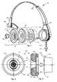
- FIG. 1is an expanded isometric view of a headset having an earphone incorporating a cushion in accordance with the present invention
- FIG. 2is a front elevation view of the output face of a first embodiment of an ear-phone cushion in accordance with the present invention
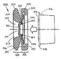
- FIG. 3is a cross-sectional, side elevation view of the earphone cushion of FIG. 2 , showing a speaker in phantom lines extracted and spaced apart from an input face of the cushion;
- FIG. 4is a front elevation view of the output face of a second embodiment of an earphone cushion in accordance with the present invention.
- FIG. 5is a cross-sectional, side elevation view of the earphone cushion of FIG. 4 , showing a speaker in phantom lines extracted and spaced apart from an input face of the cushion;
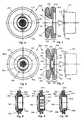
- FIG. 6is a front elevation view of the output face of a third embodiment of an earphone cushion in accordance with the present invention.
- FIG. 7is a cross-sectional, side elevation view of the earphone cushion of FIG. 6 , showing a speaker in phantom lines extracted and spaced apart from an input face of the cushion;
- FIGS. 8-10are respective cross-sectional, side elevation views of three embodiments of an acoustic plug in accordance with the present invention.
- FIG. 1is a partially expanded isometric view of a headset 10 incorporating an earphone assembly 12 , comprising an electro-acoustic transducer, or “speaker” 14 (shown in phantom outline), a comfort-enhancing earphone cushion 16 in accordance with one embodiment of the present invention, and structure 18 for acoustically coupling a through-opening 20 of the cushion 16 to a sound output face 22 of the speaker.
- the acoustical coupling structure 18comprises a second resilient ring 24 , a third ring (not visible in the figure) captivated within the second ring, and an acoustic plug 28 , and is described in more detail below in connection with FIGS. 6-10 .
- other structures for acoustically coupling the cushion 16 to the speaker 14are also possible, as described in more detail below.
- the headset 10may optionally include other elements, such as a means for acoustically coupling an output face of the cushion 16 , and hence, the earphone 12 and speaker 14 , to a lateral face of an external ear, or auricle, of a listener (not illustrated), which, in the particular embodiment illustrated in FIG. 1 , comprises a resilient, arcuate head-band having a first end 32 attached to a housing 34 for the earphone assembly 12 , and a second end 36 that includes a pad 38 for pressing against the side of the listener's head opposite to that on which the listening ear and earphone 12 are located.
- a means for acoustically coupling an output face of the cushion 16 , and hence, the earphone 12 and speaker 14 , to a lateral face of an external ear, or auricle, of a listener(not illustrated), which, in the particular embodiment illustrated in FIG. 1 , comprises a resilient, arcuate head-band having a first end 32 attached to
- earphone 12Other means for coupling the earphone 12 to the listener's ear are also known, including resilient, U-shaped yokes that hang below the listener's head of a type familiar to airline travelers, and hook-like hangars that suspend the earphone from the top edge of the external ear, and which include a resilient hinging mechanism that presses the earphone against the ear.
- the headset 10may incorporate a microphone 40 to enable two-way voice communication by the wearer.
- the microphonemay be mounted at the end of a boom 42 that is movably attached at a second end to the earphone housing 34 for adjustment relative to the wearer's mouth.
- the microphonemay comprise an omnidirectional microphone 44 that is suspended below the earphone housing 34 by one or more headset input wires 46 , as shown by the dashed outlines in FIG. 1 .
- FIGS. 2 and 3A first embodiment of a comfort-enhancing cushion 100 for an earphone in accordance with the present invention is illustrated in the front elevation and cross-sectional, side elevation views of FIGS. 2 and 3 , respectively.
- the cushion 100comprises a first resilient ring 102 having opposite input and output faces 104 , 106 , a thickness 108 between the two faces, and an opening 110 extending therethrough and defining an interior surface 112 of the ring.
- the first ring 102 of the cushion 100is shown as substantially annular in shape, the cushions of this invention are not limited to this particular shape, but may incorporate other, differently shaped rings, e.g., they may be oval, elliptical, heart-shaped, or auricular in shape.
- the material of the ring 102may vary widely, so long as it is both resilient and, as discussed below, somewhat elastic.
- the ring 102 of the cushion 100may comprise an elastomer, e.g., a polyurethane, which may be “foamed” with either open or closed cells.
- the ring 102 of the cushion 100is procured in the form of a sheet of elastomer, die-cut from the sheet, and pressed in heated molds (i.e., “thermoformed”) into the various ring configurations described herein.
- heated moldsi.e., “thermoformed”
- the input face 104 of the ring 102has means for acoustically coupling the through-opening 110 of the ring to an output face 114 of a speaker 116 , shown in phantom lines in FIG. 2 , and the output face 106 of the ring is resiliently conformable to a lateral face of a listener's external ear, or auricle.
- the speaker 116may comprise a known type of electromagnetic, piezoelectric, or electrostatic type of driving element, or a combination thereof, or even some other form of driving element, for generating sound waves from the output face of the speaker and in the direction of the arrow shown in FIG. 3 .
- the acoustical coupling meansincludes a circumferential flange 118 provided at the output face 114 of the speaker 116 .
- the through-opening 110 at the input face 104 of the ring 102is configured in size and shape to receive the speaker's output face 114 in a resilient, complementary, slide-in engagement in the direction of the arrow in FIG. 3 .
- the interior surface 112 of the ring 102is provided with a complementary, flange-retaining recess 120 located adjacent to the input face 104 of the ring that is configured to resiliently receive the flange 118 of the speaker in an elastic, “over-center” engagement.
- the opening 110 at the input face 104 of the ring 102is stretched out and over the output face 114 end flange 118 of the speaker 116 , then allowed to return elastically such that the flange is retained in the recess 120 , and the speaker's output face 114 abuts the portion of the interior surface of the ring 102 circumscribing the through-opening 110 .
- a bead of a resilient adhesive(not illustrated) can be dispensed in the recess 120 between the ring 102 and the speaker flange 118 to secure and render the coupling more permanent.
- the interior surface 112 of the ring 102flares out smoothly between the output face 114 of the speaker, when it is coupled to the ring, and to the output face 106 of the ring, thereby smoothly increasing the cross sectional area of the through-opening 110 between the two output faces.
- This change in the cross-sectional area of the opening 110permits the cushion 100 to act as an “acoustical transformer” that matches the acoustical impedances at the two respective cushion and speaker output faces 114 and 106 , for more efficient transmission of sound from the speaker to the listener's ear.
- the interior surface 102 of the opening 10can flare out uniformly, like a frusto-conical megaphone, and in another embodiment, the interior surface can flare out exponentially, like a horn.
- the first effect aboveis achieved in an earphone cushion in accordance with the present invention by “filling” or loading the resilient material of the cushion ring, e.g., an elastomer, with microcapsules of a “phase change” substance, i.e., a substance capable of an endothermic, i.e., heat-absorbing, and an exothermic, i.e., heat releasing, change of phase, e.g., from a solid to a liquid and vice-versa, at a substantially constant temperature.
- phase changei.e., a substance capable of an endothermic, i.e., heat-absorbing
- an exothermici.e., heat releasing
- the temperature at which the encapsulated substance undergoes a phase changecan be programmed, or “pre-set,” at a particular value, e.g., body temperature, at the time the microcapsules are made, and before they are incorporated into the “host,” e.g., the elastomer of the ring.
- filling the material of the cushion ring with phase-change microcapsules that are pre-set to change phase at a temperature slightly greater than body temperaturehas two effects: 1) The effective specific heat of the cushion is increased substantially, thereby rendering the cushion capable of absorbing a substantially greater amount of heat from the interface with the ear than are ordinary materials, and 2) The effective thermal conductivity of the cushion material is substantially increased, thereby enabling the cushion to conduct a greater amount of heat away from the ear interface and to the surrounding ambient air. This latter effect is enhanced even more if the elastomer of the ring is foamed with open cells, which permit circulation of the ambient into the host material and into direct contact with the microcapsules.
- phase-change microcapsule additivesare commercially available under the name “Thermasorb” from licensees of Frisby Technologies, Inc., such as 3M, Inc., St. Paul Minn., and open-celled foamed elastomers containing the microcapsules are available under the name “Comfortemp” from other licensees thereof.
- FIGS. 4 and 5A second embodiment of an ear cushion 200 in accordance with the present invention is illustrated in the front and cross-sectional side elevation views of FIGS. 4 and 5 , respectively, wherein elements that are the same or similar to those in the first embodiment of cushion 100 illustrated in FIGS. 2 and 3 are labeled with corresponding reference numerals in which the most significant digit has been incremented by one.
- the cushion 200 of the second embodimentis substantially similar to the first embodiment 100 , and differs therefrom only by the provision of at least one circumferential recess 222 in the exterior surface of the ring 202 of the cushion between the output face 206 thereof and the flange-retaining recess 220 in the interior surface 212 thereof.
- the at least one circumferential recess 222 of the second exemplary embodimentserves at least two desirable comfort functions.
- the recess 222substantially increases the external surface area of the cushion 200 , thereby enabling the cushion to transfer more heat away from the interface with the listener's ear to the ambient air.
- the recess 222serves to resiliently articulate an output face portion 224 of the cushion 200 relative to an input face portion 226 thereof, thereby rendering the output face 206 of the cushion more easily compliable to the lateral face of the listener's external ear, without: requiring uncomfortably high contact forces between the cushion and the ear for effective acoustic coupling thereof. The resulting reduction in the required contact force translates directly into enhanced, long-term headset wearer comfort.
- FIGS. 6 and 7A third exemplary embodiment of an ear cushion 300 in accordance with the present invention is illustrated in the front and cross-sectional side elevation views of FIGS. 6 and 7 , respectively, wherein elements that are the same or similar to those in the first and second embodiments of cushion 100 and 200 respectively illustrated in FIGS. 2-5 are labeled with corresponding reference numerals in which the most significant digit has been incremented by two or one, respectively, as above.
- the third embodiment of the cushion 300comprises a multi-piece structure wherein the structure associated with the input face 304 of the first resilient ring 310 for acoustically coupling the through-opening 310 of the ring 302 to the output face 314 of the speaker 316 includes the provision of a coupling flange 318 on the output face of the speaker, as described above in the first two exemplary embodiments 100 and 200 .
- a second resilient ring 330is also provided that has many of the features of the first rings 102 and 202 described above, including opposite input and output faces 332 and 334 and an opening 336 therethrough corresponding to the through-opening 310 in the first ring 302 .
- the opening 336defines an interior surface in the second ring 330 between the input and output faces 332 and 334 , and is configured at the input face to resiliently receive the output face 314 of the speaker 316 in a complementary, slide-in engagement.
- the interior surface of the second ring 302is also provided with a flange-retaining recess 320 , which is located adjacent to the input face 334 and configured to resiliently receive the flange 318 of the speaker 316 , together with a third, rigid retainer ring 340 described below, in a complementary, over-center, elastic engagement.
- the third, rigid retainer ring 340has an opening 342 through it corresponding to the respective openings 310 and 336 of the first and second rings 302 and 330 , and an outer periphery configured to be resiliently received in the flange-retaining recess 320 of the second ring in a complementary, over-center engagement, together with the flange 318 of the speaker 316 .
- the third ring 340cooperates with an acoustic plug 350 , described below, to acoustically couple the input face 304 of the first ring 302 to the output face 334 of the second ring 330 , and thus, to the output face 314 of the speaker 316 , in the manner described below.
- the acoustic plug 350 of the third embodiment of cushion 300which is shown in the enlarged, cross-section elevation views of FIGS. 8-10 , includes an input end 352 corresponding to, and configured to be received through, the respective through-openings 310 , 336 , and 342 of the first, second and third rings 302 , 330 , 340 , and to be retained therein by the retainer ring 340 .
- the plug 350further includes an output end 354 , a flange 356 circumscribing the output end, and at least one aperture 358 extending through it.
- the at least one aperture 358can comprise a single, large bore (not illustrated) that extends completely through both ends of the plug 350 , or alternatively, a large counterbore that terminates behind an output face 360 of the plug, as shown in FIGS. 8-10 , together with one or more smaller aperture extending through the output face, as shown in FIG. 6 , which can be configured in terms of their size, shape, number and distribution on the output face to acoustically “tune” the earphone.
- the input end 352 of the plug 350is inserted through the respective openings 310 , 336 , and 342 of the first, second and third rings 302 , 330 , 340 , and is retained therein by the third ring such that the flange 356 on the plug presses a first portion of the input face 304 of the first ring 302 tightly against a corresponding portion of the output face 334 of the second ring 330 , thereby acoustically coupling the input face of the first ring to the output face 314 of the speaker 316 .
- means 362use provided for retaining the input end 352 of the plug 350 in the third retainer ring 340 .
- the retaining means 362may comprise a bead of an adhesive 364 between the input end 352 of the plug 350 and the third ring 340 .
- a plurality of cams 366may be supported on the plug's input end 352 and made resiliently deflectable thereat by, e.g., a plurality of elongated slots 368 formed in the input end of tile plug, such that the input end and the cams can snap into the opening 342 of the third ring 340 with an over-center locking engagement, as shown in FIG. 9 .
- the retaining means 362can comprise complementary screw threads 370 on respective ones of the input end of the plug and in the opening 342 of the third ng, in which instance, the plug 350 screws into the opening 342 , as illustrated in FIG. 10 .
- FIG. 7An additional feature of the third embodiment of cushion 300 is illustrated in FIG. 7 , viz., that the first ring 302 can be configured such that a second portion of the input face 304 of the first ring circumscribing the flange 356 of the acoustic plug 350 is spaced apart from a corresponding portion of the output face 334 of the second ring 330 .
- the circumferential recess 322thereby defined affords the cushion 300 with substantially the same comfort benefits that the at least one circumferential recess 222 affords to the second embodiment of cushion 200 described above, viz., improved heat transfer and enhanced compliance with the external ear.
- the output face of the acoustic plugcan be faceted and plated with, e.g., a precious metal, to serve as decorative trim.
- the second ring of the third embodimentcan be made of a resilient material having a different texture and/or color for ornamental purposes, or covered with a simulated leather called “leatherette,” to lend a rich look and feel to the cushion.
- a plurality of circumferential recessescan be provided the exterior cushion of the second embodiment to improve its comfort benefits even further.
Landscapes
- Physics & Mathematics (AREA)
- Engineering & Computer Science (AREA)
- Acoustics & Sound (AREA)
- Signal Processing (AREA)
- Headphones And Earphones (AREA)
Abstract
Description
Claims (26)
Priority Applications (1)
| Application Number | Priority Date | Filing Date | Title |
|---|---|---|---|
| US10/043,613US6856690B1 (en) | 2002-01-09 | 2002-01-09 | Comfortable earphone cushions |
Applications Claiming Priority (1)
| Application Number | Priority Date | Filing Date | Title |
|---|---|---|---|
| US10/043,613US6856690B1 (en) | 2002-01-09 | 2002-01-09 | Comfortable earphone cushions |
Publications (1)
| Publication Number | Publication Date |
|---|---|
| US6856690B1true US6856690B1 (en) | 2005-02-15 |
Family
ID=34114829
Family Applications (1)
| Application Number | Title | Priority Date | Filing Date |
|---|---|---|---|
| US10/043,613Expired - LifetimeUS6856690B1 (en) | 2002-01-09 | 2002-01-09 | Comfortable earphone cushions |
Country Status (1)
| Country | Link |
|---|---|
| US (1) | US6856690B1 (en) |
Cited By (34)
| Publication number | Priority date | Publication date | Assignee | Title |
|---|---|---|---|---|
| US20050089185A1 (en)* | 2003-10-28 | 2005-04-28 | Allen Robin K. | Headset ear seal employing phase change material |
| US20060135223A1 (en)* | 2004-12-21 | 2006-06-22 | Samsung Electronics Co., Ltd. | Wireless headset phone of ear-worn type |
| US20060188121A1 (en)* | 2004-04-16 | 2006-08-24 | Sony Corporation | Headphone device |
| US20060280327A1 (en)* | 2005-06-09 | 2006-12-14 | Kabushiki Kaisha Toshiba | Speaker device and acoustic output method thereof as well as image display apparatus |
| US20080128198A1 (en)* | 2006-12-04 | 2008-06-05 | Yu Du | Sound-attenuating earmuff having isolated double-shell structure |
| US20100254562A1 (en)* | 2007-12-15 | 2010-10-07 | Koo Youn Young | Earphone via drumhead |
| US20110211723A1 (en)* | 2006-06-30 | 2011-09-01 | Annunziato Kevin P | Earphone cushions |
| CN101137249B (en)* | 2006-08-30 | 2012-01-04 | 固昌通讯股份有限公司 | earphone |
| US20120070027A1 (en)* | 2009-03-02 | 2012-03-22 | Bettina Ridler | Headset With Magnetically Attached Ear Pad |
| US20140037123A1 (en)* | 2012-06-04 | 2014-02-06 | Sennheiser Electronic Gmbh & Co. Kg | Seal Assembly for an in-ear and in-ear |
| CN103597857A (en)* | 2011-03-11 | 2014-02-19 | 泰达有限责任公司 | Earpuff |
| CN103686511A (en)* | 2012-09-17 | 2014-03-26 | 森海塞尔通信公司 | Ear appliance |
| US8746397B2 (en) | 2011-10-07 | 2014-06-10 | Hearing Components, Inc. | Foam cushion for headphones |
| WO2014102191A1 (en) | 2012-12-28 | 2014-07-03 | Gn Netcom A/S | Metal earpad |
| WO2014153212A1 (en)* | 2013-03-14 | 2014-09-25 | Verto Medical Solutions, LLC | Earphones |
| CN104349257A (en)* | 2013-08-01 | 2015-02-11 | 奥迪康有限公司 | Bone-sealed audio device |
| US9094770B2 (en)* | 2003-11-13 | 2015-07-28 | Viscot Medical, Llc | Hearing aid that facilitates removal of earwax and trapping of moisture |
| US9215522B2 (en) | 2006-06-30 | 2015-12-15 | Bose Corporation | Earphones |
| US9462366B2 (en) | 2014-03-27 | 2016-10-04 | Bose Corporation | Earpieces having flexible flaps |
| US20180109858A1 (en)* | 2016-10-13 | 2018-04-19 | Bose Corporation | Acoustaical devices employing phase change materials |
| US20180109861A1 (en)* | 2016-10-13 | 2018-04-19 | Bose Corporation | Earpiece employing cooling and sensation inducing materials |
| US20180160216A1 (en)* | 2016-12-06 | 2018-06-07 | Bose Corporation | Earpieces employing viscoelastic materials |
| US20180346678A1 (en)* | 2017-05-30 | 2018-12-06 | Bose Corporation | Breathable earpieces |
| DE102008020264B4 (en) | 2008-04-22 | 2018-12-13 | Sennheiser Electronic Gmbh & Co. Kg | Handset and headset |
| US10187716B1 (en)* | 2017-09-27 | 2019-01-22 | Bose Corporation | Composite earcushion |
| US10419861B2 (en) | 2011-05-24 | 2019-09-17 | Cochlear Limited | Convertibility of a bone conduction device |
| US10880633B2 (en) | 2016-06-22 | 2020-12-29 | Dolby Laboratories Licensing Corporation | Headphones and headphone systems |
| US10959012B2 (en) | 2008-04-07 | 2021-03-23 | Koss Corporation | System with wireless earphones |
| US11044542B2 (en)* | 2017-09-27 | 2021-06-22 | Bose Corporation | Composite earcushion |
| US11070905B2 (en) | 2017-01-25 | 2021-07-20 | Hewlett-Packard Development Company, L.P. | Self-cooling headset |
| US11089413B2 (en) | 2012-08-28 | 2021-08-10 | Cochlear Limited | Removable attachment of a passive transcutaneous bone conduction device with limited skin deformation |
| USD945981S1 (en)* | 2020-01-23 | 2022-03-15 | Stephen John Rois | Audio headphones |
| US11528550B2 (en) | 2019-07-25 | 2022-12-13 | Hewlett-Packard Development Company, L.P. | Self-cooling headset |
| US20250088782A1 (en)* | 2023-09-07 | 2025-03-13 | Merry Electronics(Shenzhen) Co., Ltd. | Cushion for wearable device |
Citations (59)
| Publication number | Priority date | Publication date | Assignee | Title |
|---|---|---|---|---|
| US1368307A (en) | 1918-04-13 | 1921-02-15 | Western Electric Co | Earpiece |
| US2235372A (en) | 1938-02-22 | 1941-03-18 | Siemens App Und Maschinen Gmbh | Receiver headband |
| US2408494A (en) | 1945-06-07 | 1946-10-01 | Paul S Veneklasen | Earphone socket |
| US2468721A (en) | 1945-07-09 | 1949-04-26 | Volkmann John | Earphone socket and noise shield |
| US2856469A (en) | 1955-12-05 | 1958-10-14 | Morse Milton | Earphone barrier device |
| US2989598A (en) | 1960-02-24 | 1961-06-20 | Martin L Touger | Hard shell liquid seal earmuff with isolated inner close coupling ear shell |
| US3030458A (en) | 1958-10-17 | 1962-04-17 | Electric Storage Battery Co | Detachable liner for headsets |
| US3051961A (en) | 1960-05-11 | 1962-09-04 | Clark Co Inc David | Ear protctor and seal therefor |
| US3073410A (en) | 1959-12-30 | 1963-01-15 | Electric Storage Battery Co | Headset |
| US3134456A (en) | 1960-02-04 | 1964-05-26 | Clark Co Inc David | Wide range communication and sound attenuation device |
| US3160717A (en)* | 1962-03-21 | 1964-12-08 | American Optical Corp | Ear protectors |
| US3220505A (en) | 1964-04-01 | 1965-11-30 | Willard B Hargrave | Audiometric headset |
| US3456263A (en) | 1967-05-09 | 1969-07-22 | Gentex Corp | Rigid shell helmet with ear cup |
| US3571813A (en) | 1969-05-21 | 1971-03-23 | Bolt Beranek & Newman | Acoustical ear muff with cone-type cushions |
| US3602329A (en) | 1970-01-07 | 1971-08-31 | Columbia Broadcasting Systems | Conformal ear enclosure |
| US3645354A (en) | 1970-10-01 | 1972-02-29 | Telex Corp The | Earphone pad |
| US3798393A (en) | 1969-02-17 | 1974-03-19 | Akg Akustische Kino Geraete | Headphone construction |
| US4005278A (en)* | 1974-09-16 | 1977-01-25 | Akg Akustische U. Kino-Gerate Gesellschaft M.B.H. | Headphone |
| US4041256A (en) | 1975-05-06 | 1977-08-09 | Victor Company Of Japan, Limited | Open-back type headphone with a detachable attachment |
| US4058688A (en) | 1975-05-27 | 1977-11-15 | Matsushita Electric Industrial Co., Ltd. | Headphone |
| US4071717A (en) | 1975-04-08 | 1978-01-31 | Akg Akustische U. Kino-Gerate Gesellschaft M.B.H. | Headphone earpiece |
| US4087653A (en) | 1975-12-17 | 1978-05-02 | Gentex Corporation | Sound attenuating earcup assembly provided with receivers and contact microphone |
| US4156118A (en) | 1978-04-10 | 1979-05-22 | Hargrave Frances E | Audiometric headset |
| US4160135A (en) | 1977-04-15 | 1979-07-03 | Akg Akustische U.Kino-Gerate Gesellschaft M.B.H. | Closed earphone construction |
| US4170275A (en) | 1977-10-19 | 1979-10-09 | Koss Corporation | Ear cushion |
| US4239945A (en) | 1976-12-15 | 1980-12-16 | Matsushita Electric Industrial Co., Ltd. | Sealed headphone |
| US4278852A (en) | 1977-08-31 | 1981-07-14 | AKG Akustische u. Kino-Gertate Gesellschaft m.b.H. | Earphone construction |
| US4302635A (en) | 1980-01-04 | 1981-11-24 | Koss Corporation | Headphone construction |
| US4389542A (en) | 1979-08-23 | 1983-06-21 | Akg Akustische U. Kino-Gerate | Orthodynamic headphone |
| US4437538A (en) | 1982-03-30 | 1984-03-20 | Ingemar Ohlsson | Ear-cap |
| US4523661A (en)* | 1983-05-16 | 1985-06-18 | Gentex Corporation | Earphone system for use in large-cavity earcups |
| US4529058A (en) | 1984-09-17 | 1985-07-16 | Emery Earl L | Earphones |
| US4572324A (en) | 1983-05-26 | 1986-02-25 | Akg Akustische U.Kino-Gerate Gesellschaft Mbh | Ear piece construction |
| US4634816A (en) | 1984-05-21 | 1987-01-06 | Northern Telecom Limited | Communications headset |
| US4674134A (en) | 1985-03-25 | 1987-06-23 | Bilsom Ab | Earmuff having sealing ring including liquid and foam plastic layers |
| US4689822A (en) | 1986-01-29 | 1987-08-25 | Houng Huang Chiang | Headset |
| US4771454A (en) | 1987-04-14 | 1988-09-13 | Wilcox Jr Edward R | Ruggedized ear protector and communications headset |
| US4856118A (en) | 1987-02-11 | 1989-08-15 | Bose Corporation | Headphone cushioning |
| US4875233A (en) | 1987-10-16 | 1989-10-17 | Derhaag Robert L | Headset construction and method of making same |
| US4922542A (en) | 1987-12-28 | 1990-05-01 | Roman Sapiejewski | Headphone comfort |
| US4958697A (en) | 1989-09-11 | 1990-09-25 | The United States Of America As Represented By The Secretary Of The Army | Anatomically shaped earseals for headsets |
| US4989271A (en) | 1989-08-24 | 1991-02-05 | Bose Corporation | Headphone cushioning |
| US5003631A (en) | 1989-10-05 | 1991-04-02 | Northrop Corporation | Flight helmet with headset |
| US5018599A (en) | 1988-10-03 | 1991-05-28 | Sony Corporation | Headphone device |
| US5138722A (en) | 1991-07-02 | 1992-08-18 | David Clark Company Inc. | Headset ear seal |
| US5555554A (en) | 1995-06-08 | 1996-09-10 | Stanton Magnetics, Inc. | Vented headset speaker |
| US5677964A (en) | 1996-09-16 | 1997-10-14 | Sun; Ming-Han | Earphone |
| USD391575S (en) | 1995-04-21 | 1998-03-03 | David Clark Company Inc. | Headset earcup |
| US5736785A (en) | 1996-12-20 | 1998-04-07 | Industrial Technology Research Institute | Semiconductor package for improving the capability of spreading heat |
| US5761298A (en) | 1996-05-31 | 1998-06-02 | Plantronics, Inc. | Communications headset with universally adaptable receiver and voice transmitter |
| US5821468A (en) | 1996-05-20 | 1998-10-13 | David Clark Company, Inc. | Laminated nap comfort cover for ear seal |
| US5911314A (en) | 1998-03-31 | 1999-06-15 | David Clark Company Inc. | Headset ear seal |
| US5960094A (en) | 1996-01-24 | 1999-09-28 | Gn Netcom, Inc. | Communications headset |
| US6097809A (en) | 1992-09-29 | 2000-08-01 | Unex Corporation | Adjustable telephone headset |
| US6099894A (en)* | 1998-07-27 | 2000-08-08 | Frisby Technologies, Inc. | Gel-coated microcapsules |
| US6163615A (en) | 1997-08-06 | 2000-12-19 | University Research & Engineers & Associates, Inc. | Circumaural ear cup audio seal for use in connection with a headset, ear defender, helmet and the like |
| US6252970B1 (en) | 1999-09-10 | 2001-06-26 | Antonio Precise Products Manufactory Limited | Headphone |
| US6295366B1 (en) | 1999-03-24 | 2001-09-25 | Flightcom Corporation | Aircraft headset |
| JP2001309478A (en)* | 2000-04-19 | 2001-11-02 | Bridgestone Corp | Ear pad material |
- 2002
- 2002-01-09USUS10/043,613patent/US6856690B1/ennot_activeExpired - Lifetime
Patent Citations (60)
| Publication number | Priority date | Publication date | Assignee | Title |
|---|---|---|---|---|
| US1368307A (en) | 1918-04-13 | 1921-02-15 | Western Electric Co | Earpiece |
| US2235372A (en) | 1938-02-22 | 1941-03-18 | Siemens App Und Maschinen Gmbh | Receiver headband |
| US2408494A (en) | 1945-06-07 | 1946-10-01 | Paul S Veneklasen | Earphone socket |
| US2468721A (en) | 1945-07-09 | 1949-04-26 | Volkmann John | Earphone socket and noise shield |
| US2856469A (en) | 1955-12-05 | 1958-10-14 | Morse Milton | Earphone barrier device |
| US3030458A (en) | 1958-10-17 | 1962-04-17 | Electric Storage Battery Co | Detachable liner for headsets |
| US3073410A (en) | 1959-12-30 | 1963-01-15 | Electric Storage Battery Co | Headset |
| US3134456A (en) | 1960-02-04 | 1964-05-26 | Clark Co Inc David | Wide range communication and sound attenuation device |
| US2989598A (en) | 1960-02-24 | 1961-06-20 | Martin L Touger | Hard shell liquid seal earmuff with isolated inner close coupling ear shell |
| US3051961A (en) | 1960-05-11 | 1962-09-04 | Clark Co Inc David | Ear protctor and seal therefor |
| US3160717A (en)* | 1962-03-21 | 1964-12-08 | American Optical Corp | Ear protectors |
| US3220505A (en) | 1964-04-01 | 1965-11-30 | Willard B Hargrave | Audiometric headset |
| US3456263A (en) | 1967-05-09 | 1969-07-22 | Gentex Corp | Rigid shell helmet with ear cup |
| US3798393A (en) | 1969-02-17 | 1974-03-19 | Akg Akustische Kino Geraete | Headphone construction |
| US3571813A (en) | 1969-05-21 | 1971-03-23 | Bolt Beranek & Newman | Acoustical ear muff with cone-type cushions |
| US3602329A (en) | 1970-01-07 | 1971-08-31 | Columbia Broadcasting Systems | Conformal ear enclosure |
| US3645354A (en) | 1970-10-01 | 1972-02-29 | Telex Corp The | Earphone pad |
| US4005278A (en)* | 1974-09-16 | 1977-01-25 | Akg Akustische U. Kino-Gerate Gesellschaft M.B.H. | Headphone |
| US4071717A (en) | 1975-04-08 | 1978-01-31 | Akg Akustische U. Kino-Gerate Gesellschaft M.B.H. | Headphone earpiece |
| US4041256A (en) | 1975-05-06 | 1977-08-09 | Victor Company Of Japan, Limited | Open-back type headphone with a detachable attachment |
| US4058688A (en) | 1975-05-27 | 1977-11-15 | Matsushita Electric Industrial Co., Ltd. | Headphone |
| US4087653A (en) | 1975-12-17 | 1978-05-02 | Gentex Corporation | Sound attenuating earcup assembly provided with receivers and contact microphone |
| US4239945A (en) | 1976-12-15 | 1980-12-16 | Matsushita Electric Industrial Co., Ltd. | Sealed headphone |
| US4160135A (en) | 1977-04-15 | 1979-07-03 | Akg Akustische U.Kino-Gerate Gesellschaft M.B.H. | Closed earphone construction |
| US4278852A (en) | 1977-08-31 | 1981-07-14 | AKG Akustische u. Kino-Gertate Gesellschaft m.b.H. | Earphone construction |
| US4170275A (en) | 1977-10-19 | 1979-10-09 | Koss Corporation | Ear cushion |
| US4156118A (en) | 1978-04-10 | 1979-05-22 | Hargrave Frances E | Audiometric headset |
| US4389542A (en) | 1979-08-23 | 1983-06-21 | Akg Akustische U. Kino-Gerate | Orthodynamic headphone |
| US4302635A (en) | 1980-01-04 | 1981-11-24 | Koss Corporation | Headphone construction |
| US4437538A (en) | 1982-03-30 | 1984-03-20 | Ingemar Ohlsson | Ear-cap |
| US4523661A (en)* | 1983-05-16 | 1985-06-18 | Gentex Corporation | Earphone system for use in large-cavity earcups |
| US4572324A (en) | 1983-05-26 | 1986-02-25 | Akg Akustische U.Kino-Gerate Gesellschaft Mbh | Ear piece construction |
| US4634816A (en) | 1984-05-21 | 1987-01-06 | Northern Telecom Limited | Communications headset |
| US4529058A (en) | 1984-09-17 | 1985-07-16 | Emery Earl L | Earphones |
| US4674134A (en) | 1985-03-25 | 1987-06-23 | Bilsom Ab | Earmuff having sealing ring including liquid and foam plastic layers |
| US4689822A (en) | 1986-01-29 | 1987-08-25 | Houng Huang Chiang | Headset |
| US4856118A (en) | 1987-02-11 | 1989-08-15 | Bose Corporation | Headphone cushioning |
| US4771454A (en) | 1987-04-14 | 1988-09-13 | Wilcox Jr Edward R | Ruggedized ear protector and communications headset |
| US4875233A (en) | 1987-10-16 | 1989-10-17 | Derhaag Robert L | Headset construction and method of making same |
| US4922542A (en) | 1987-12-28 | 1990-05-01 | Roman Sapiejewski | Headphone comfort |
| US5018599A (en) | 1988-10-03 | 1991-05-28 | Sony Corporation | Headphone device |
| US4989271A (en) | 1989-08-24 | 1991-02-05 | Bose Corporation | Headphone cushioning |
| US4958697A (en) | 1989-09-11 | 1990-09-25 | The United States Of America As Represented By The Secretary Of The Army | Anatomically shaped earseals for headsets |
| US5003631A (en) | 1989-10-05 | 1991-04-02 | Northrop Corporation | Flight helmet with headset |
| US5138722A (en) | 1991-07-02 | 1992-08-18 | David Clark Company Inc. | Headset ear seal |
| US6097809A (en) | 1992-09-29 | 2000-08-01 | Unex Corporation | Adjustable telephone headset |
| USD391575S (en) | 1995-04-21 | 1998-03-03 | David Clark Company Inc. | Headset earcup |
| US5555554A (en) | 1995-06-08 | 1996-09-10 | Stanton Magnetics, Inc. | Vented headset speaker |
| US5960094A (en) | 1996-01-24 | 1999-09-28 | Gn Netcom, Inc. | Communications headset |
| US6101260A (en) | 1996-01-24 | 2000-08-08 | Gn Netcom, Inc. | Communication headset |
| US5821468A (en) | 1996-05-20 | 1998-10-13 | David Clark Company, Inc. | Laminated nap comfort cover for ear seal |
| US5761298A (en) | 1996-05-31 | 1998-06-02 | Plantronics, Inc. | Communications headset with universally adaptable receiver and voice transmitter |
| US5677964A (en) | 1996-09-16 | 1997-10-14 | Sun; Ming-Han | Earphone |
| US5736785A (en) | 1996-12-20 | 1998-04-07 | Industrial Technology Research Institute | Semiconductor package for improving the capability of spreading heat |
| US6163615A (en) | 1997-08-06 | 2000-12-19 | University Research & Engineers & Associates, Inc. | Circumaural ear cup audio seal for use in connection with a headset, ear defender, helmet and the like |
| US5911314A (en) | 1998-03-31 | 1999-06-15 | David Clark Company Inc. | Headset ear seal |
| US6099894A (en)* | 1998-07-27 | 2000-08-08 | Frisby Technologies, Inc. | Gel-coated microcapsules |
| US6295366B1 (en) | 1999-03-24 | 2001-09-25 | Flightcom Corporation | Aircraft headset |
| US6252970B1 (en) | 1999-09-10 | 2001-06-26 | Antonio Precise Products Manufactory Limited | Headphone |
| JP2001309478A (en)* | 2000-04-19 | 2001-11-02 | Bridgestone Corp | Ear pad material |
Cited By (70)
| Publication number | Priority date | Publication date | Assignee | Title |
|---|---|---|---|---|
| US20050089185A1 (en)* | 2003-10-28 | 2005-04-28 | Allen Robin K. | Headset ear seal employing phase change material |
| US9094770B2 (en)* | 2003-11-13 | 2015-07-28 | Viscot Medical, Llc | Hearing aid that facilitates removal of earwax and trapping of moisture |
| US20060188121A1 (en)* | 2004-04-16 | 2006-08-24 | Sony Corporation | Headphone device |
| US7983438B2 (en)* | 2004-04-16 | 2011-07-19 | Sony Corporation | Headphone device |
| US20060135223A1 (en)* | 2004-12-21 | 2006-06-22 | Samsung Electronics Co., Ltd. | Wireless headset phone of ear-worn type |
| US7539525B2 (en)* | 2004-12-21 | 2009-05-26 | Samsung Electronics Co., Ltd | Wireless headset phone of ear-worn type |
| US20060280327A1 (en)* | 2005-06-09 | 2006-12-14 | Kabushiki Kaisha Toshiba | Speaker device and acoustic output method thereof as well as image display apparatus |
| US9215522B2 (en) | 2006-06-30 | 2015-12-15 | Bose Corporation | Earphones |
| US8355522B2 (en)* | 2006-06-30 | 2013-01-15 | Bose Corporation | Earphone cushions |
| US10327062B2 (en) | 2006-06-30 | 2019-06-18 | Bose Corporation | Earphones |
| US20110211723A1 (en)* | 2006-06-30 | 2011-09-01 | Annunziato Kevin P | Earphone cushions |
| CN101137249B (en)* | 2006-08-30 | 2012-01-04 | 固昌通讯股份有限公司 | earphone |
| US20080128198A1 (en)* | 2006-12-04 | 2008-06-05 | Yu Du | Sound-attenuating earmuff having isolated double-shell structure |
| US7854294B2 (en)* | 2006-12-04 | 2010-12-21 | Adaptive Technologies, Inc. | Sound-attenuating earmuff having isolated double-shell structure |
| US20100218775A1 (en)* | 2006-12-04 | 2010-09-02 | Yu Du | Sound-attenuating earmuff having isolated double-shell structure |
| US7703572B2 (en)* | 2006-12-04 | 2010-04-27 | Adaptive Technologies, Inc. | Sound-attenuating earmuff having isolated double-shell structure |
| US8213663B2 (en)* | 2007-12-15 | 2012-07-03 | Koo Youn Young | Earphone via drumhead |
| US20100254562A1 (en)* | 2007-12-15 | 2010-10-07 | Koo Youn Young | Earphone via drumhead |
| US11425486B2 (en) | 2008-04-07 | 2022-08-23 | Koss Corporation | Wireless earphone that transitions between wireless networks |
| US11606638B2 (en) | 2008-04-07 | 2023-03-14 | Koss Corporation | Wireless earphones with digital signal processors |
| US11582546B2 (en) | 2008-04-07 | 2023-02-14 | Koss Corporation | Wireless earphones with hanger bars |
| US11653139B2 (en) | 2008-04-07 | 2023-05-16 | Koss Corporation | Wireless earphones that play lossy compressed streaming audio |
| US11425485B2 (en) | 2008-04-07 | 2022-08-23 | Koss Corporation | Wireless earphone that transitions between wireless networks |
| US11792561B2 (en) | 2008-04-07 | 2023-10-17 | Koss Corporation | Wireless earphones that play lossy compressed streaming audio |
| US10959011B2 (en) | 2008-04-07 | 2021-03-23 | Koss Corporation | System with wireless earphones |
| US10959012B2 (en) | 2008-04-07 | 2021-03-23 | Koss Corporation | System with wireless earphones |
| DE102008020264B4 (en) | 2008-04-22 | 2018-12-13 | Sennheiser Electronic Gmbh & Co. Kg | Handset and headset |
| US9332337B2 (en) | 2009-03-02 | 2016-05-03 | Gn Netcom A/S | Headset with magnetically attached ear pad |
| US20120070027A1 (en)* | 2009-03-02 | 2012-03-22 | Bettina Ridler | Headset With Magnetically Attached Ear Pad |
| CN103597857A (en)* | 2011-03-11 | 2014-02-19 | 泰达有限责任公司 | Earpuff |
| US11546708B2 (en) | 2011-05-24 | 2023-01-03 | Cochlear Limited | Convertibility of a bone conduction device |
| US10419861B2 (en) | 2011-05-24 | 2019-09-17 | Cochlear Limited | Convertibility of a bone conduction device |
| US10848883B2 (en) | 2011-05-24 | 2020-11-24 | Cochlear Limited | Convertibility of a bone conduction device |
| US11910166B2 (en) | 2011-05-24 | 2024-02-20 | Cochlear Limited | Convertibility of a bone conduction device |
| US9902127B2 (en) | 2011-10-07 | 2018-02-27 | Hearing Components, Inc. | Foam cushion for headphones |
| US9254227B2 (en) | 2011-10-07 | 2016-02-09 | Hearing Components, Inc. | Foam cushion for headphones |
| US8746397B2 (en) | 2011-10-07 | 2014-06-10 | Hearing Components, Inc. | Foam cushion for headphones |
| US9555598B2 (en) | 2011-10-07 | 2017-01-31 | Hearing Components, Inc. | Foam cushion for headphones |
| US8960366B2 (en) | 2011-10-07 | 2015-02-24 | Hearing Components, Inc. | Foam cushion for headphones |
| US20140037123A1 (en)* | 2012-06-04 | 2014-02-06 | Sennheiser Electronic Gmbh & Co. Kg | Seal Assembly for an in-ear and in-ear |
| US9071905B2 (en)* | 2012-06-04 | 2015-06-30 | Sennheiser Electronic Gmbh & Co. Kg | Seal assembly for an in-ear and in-ear |
| US11089413B2 (en) | 2012-08-28 | 2021-08-10 | Cochlear Limited | Removable attachment of a passive transcutaneous bone conduction device with limited skin deformation |
| CN103686511A (en)* | 2012-09-17 | 2014-03-26 | 森海塞尔通信公司 | Ear appliance |
| US9414966B2 (en)* | 2012-12-28 | 2016-08-16 | Gn Netcom A/S | Metal earpad |
| US20150358712A1 (en)* | 2012-12-28 | 2015-12-10 | Gn Netcom A/S | Metal earpad |
| WO2014102191A1 (en) | 2012-12-28 | 2014-07-03 | Gn Netcom A/S | Metal earpad |
| WO2014153212A1 (en)* | 2013-03-14 | 2014-09-25 | Verto Medical Solutions, LLC | Earphones |
| US9106996B2 (en) | 2013-03-14 | 2015-08-11 | Harman International Industries, Incorporated | Earphones |
| CN104349257A (en)* | 2013-08-01 | 2015-02-11 | 奥迪康有限公司 | Bone-sealed audio device |
| US9462366B2 (en) | 2014-03-27 | 2016-10-04 | Bose Corporation | Earpieces having flexible flaps |
| US10880633B2 (en) | 2016-06-22 | 2020-12-29 | Dolby Laboratories Licensing Corporation | Headphones and headphone systems |
| US11330356B2 (en) | 2016-06-22 | 2022-05-10 | Dolby Laboratories Licensing Corporation | Headphones and headphone systems |
| US11937042B2 (en) | 2016-06-22 | 2024-03-19 | Dolby Laboratories Licensing Corporation | Headphones and headphone systems |
| US10531174B2 (en)* | 2016-10-13 | 2020-01-07 | Bose Corporation | Earpiece employing cooling and sensation inducing materials |
| US20180109858A1 (en)* | 2016-10-13 | 2018-04-19 | Bose Corporation | Acoustaical devices employing phase change materials |
| US10602250B2 (en)* | 2016-10-13 | 2020-03-24 | Bose Corporation | Acoustaical devices employing phase change materials |
| US20180109861A1 (en)* | 2016-10-13 | 2018-04-19 | Bose Corporation | Earpiece employing cooling and sensation inducing materials |
| US20180160216A1 (en)* | 2016-12-06 | 2018-06-07 | Bose Corporation | Earpieces employing viscoelastic materials |
| US10623846B2 (en)* | 2016-12-06 | 2020-04-14 | Bose Corporation | Earpieces employing viscoelastic materials |
| US11070905B2 (en) | 2017-01-25 | 2021-07-20 | Hewlett-Packard Development Company, L.P. | Self-cooling headset |
| US20180346678A1 (en)* | 2017-05-30 | 2018-12-06 | Bose Corporation | Breathable earpieces |
| US20190149904A1 (en)* | 2017-09-27 | 2019-05-16 | Bose Corporation | Composite earcushion |
| US10187716B1 (en)* | 2017-09-27 | 2019-01-22 | Bose Corporation | Composite earcushion |
| US11044542B2 (en)* | 2017-09-27 | 2021-06-22 | Bose Corporation | Composite earcushion |
| US10659861B2 (en)* | 2017-09-27 | 2020-05-19 | Bose Corporation | Composite earcushion |
| US11528550B2 (en) | 2019-07-25 | 2022-12-13 | Hewlett-Packard Development Company, L.P. | Self-cooling headset |
| USD981365S1 (en) | 2020-01-23 | 2023-03-21 | Stephen John Rois | Audio headphones |
| USD945981S1 (en)* | 2020-01-23 | 2022-03-15 | Stephen John Rois | Audio headphones |
| USD960125S1 (en) | 2020-01-23 | 2022-08-09 | Stephen John Rois | Audio headphones |
| US20250088782A1 (en)* | 2023-09-07 | 2025-03-13 | Merry Electronics(Shenzhen) Co., Ltd. | Cushion for wearable device |
Similar Documents
| Publication | Publication Date | Title |
|---|---|---|
| US6856690B1 (en) | Comfortable earphone cushions | |
| US10231048B2 (en) | Ergonomic earpiece with attachment mount | |
| US4736435A (en) | Ear piece transducer | |
| CN102648639B (en) | Earphone | |
| MXPA06002815A (en) | Audio apparatus. | |
| US20040008855A1 (en) | Ear clasp headset | |
| US20160050477A1 (en) | In-the-ear earphone, (its variantions) and methods of wearing | |
| CN105307066A (en) | Monaural wireless headset | |
| US20070105598A1 (en) | Audio headset | |
| JP2002506297A (en) | Buffer cover to prevent pain when using earphones | |
| CN217011123U (en) | Bone conduction earphone | |
| CN114339511A (en) | Wireless Headphones | |
| US20060147079A1 (en) | Earphone | |
| CN201758441U (en) | A safety protection type passive noise reduction earphone | |
| US20220232308A1 (en) | Modular Earphone | |
| CN212752573U (en) | Earphone and earphone sealing sleeve | |
| CN212231716U (en) | Earphone set | |
| KR200208110Y1 (en) | Multi-function cover for sound receive device | |
| JPS6379500A (en) | Earphone | |
| KR102315063B1 (en) | Semi-canal type wireless earset | |
| JPS5912235B2 (en) | ear speaker | |
| CN210840047U (en) | Be applied to bone conduction sound generating mechanism's vibrating diaphragm and subassembly of raising one's voice | |
| CN221633928U (en) | An open-ear headphone that is comfortable to wear | |
| CN221283320U (en) | Ear clip type earphone with stable sound quality | |
| KR102692919B1 (en) | Bone Conduction Type Piezoelctric Earphone |
Legal Events
| Date | Code | Title | Description |
|---|---|---|---|
| AS | Assignment | Owner name:PLANTRONICS, INC., CALIFORNIA Free format text:ASSIGNMENT OF ASSIGNORS INTEREST;ASSIGNOR:SKULLEY, GERALD W.;REEL/FRAME:012434/0307 Effective date:20020107 | |
| STCF | Information on status: patent grant | Free format text:PATENTED CASE | |
| FPAY | Fee payment | Year of fee payment:4 | |
| FPAY | Fee payment | Year of fee payment:8 | |
| FEPP | Fee payment procedure | Free format text:PAYER NUMBER DE-ASSIGNED (ORIGINAL EVENT CODE: RMPN); ENTITY STATUS OF PATENT OWNER: LARGE ENTITY Free format text:PAYOR NUMBER ASSIGNED (ORIGINAL EVENT CODE: ASPN); ENTITY STATUS OF PATENT OWNER: LARGE ENTITY | |
| FPAY | Fee payment | Year of fee payment:12 | |
| AS | Assignment | Owner name:WELLS FARGO BANK, NATIONAL ASSOCIATION, NORTH CAROLINA Free format text:SECURITY AGREEMENT;ASSIGNORS:PLANTRONICS, INC.;POLYCOM, INC.;REEL/FRAME:046491/0915 Effective date:20180702 Owner name:WELLS FARGO BANK, NATIONAL ASSOCIATION, NORTH CARO Free format text:SECURITY AGREEMENT;ASSIGNORS:PLANTRONICS, INC.;POLYCOM, INC.;REEL/FRAME:046491/0915 Effective date:20180702 | |
| AS | Assignment | Owner name:POLYCOM, INC., CALIFORNIA Free format text:RELEASE OF PATENT SECURITY INTERESTS;ASSIGNOR:WELLS FARGO BANK, NATIONAL ASSOCIATION;REEL/FRAME:061356/0366 Effective date:20220829 Owner name:PLANTRONICS, INC., CALIFORNIA Free format text:RELEASE OF PATENT SECURITY INTERESTS;ASSIGNOR:WELLS FARGO BANK, NATIONAL ASSOCIATION;REEL/FRAME:061356/0366 Effective date:20220829 |