US6856293B2 - Adjustable antenna - Google Patents
Adjustable antennaDownload PDFInfo
- Publication number
- US6856293B2 US6856293B2US10/471,189US47118903AUS6856293B2US 6856293 B2US6856293 B2US 6856293B2US 47118903 AUS47118903 AUS 47118903AUS 6856293 B2US6856293 B2US 6856293B2
- Authority
- US
- United States
- Prior art keywords
- antenna
- antenna structure
- radiating element
- electromagnet
- magnetostrictive material
- Prior art date
- Legal status (The legal status is an assumption and is not a legal conclusion. Google has not performed a legal analysis and makes no representation as to the accuracy of the status listed.)
- Expired - Fee Related
Links
- 239000000463materialSubstances0.000claimsabstractdescription15
- 230000005404monopoleEffects0.000claimsdescription17
- 238000004804windingMethods0.000claimsdescription16
- 230000008859changeEffects0.000claimsdescription4
- 230000008878couplingEffects0.000claimsdescription2
- 238000010168coupling processMethods0.000claimsdescription2
- 238000005859coupling reactionMethods0.000claimsdescription2
- 230000004907fluxEffects0.000description4
- 230000008901benefitEffects0.000description3
- 239000004020conductorSubstances0.000description3
- 238000000034methodMethods0.000description2
- 239000003990capacitorSubstances0.000description1
- 230000001413cellular effectEffects0.000description1
- 239000013078crystalSubstances0.000description1
- 230000006870functionEffects0.000description1
- 238000004519manufacturing processMethods0.000description1
- 230000009466transformationEffects0.000description1
Images


Classifications
- H—ELECTRICITY
- H01—ELECTRIC ELEMENTS
- H01Q—ANTENNAS, i.e. RADIO AERIALS
- H01Q1/00—Details of, or arrangements associated with, antennas
- H01Q1/12—Supports; Mounting means
- H01Q1/22—Supports; Mounting means by structural association with other equipment or articles
- H01Q1/24—Supports; Mounting means by structural association with other equipment or articles with receiving set
- H01Q1/241—Supports; Mounting means by structural association with other equipment or articles with receiving set used in mobile communications, e.g. GSM
- H01Q1/242—Supports; Mounting means by structural association with other equipment or articles with receiving set used in mobile communications, e.g. GSM specially adapted for hand-held use
- H01Q1/243—Supports; Mounting means by structural association with other equipment or articles with receiving set used in mobile communications, e.g. GSM specially adapted for hand-held use with built-in antennas
- H—ELECTRICITY
- H01—ELECTRIC ELEMENTS
- H01Q—ANTENNAS, i.e. RADIO AERIALS
- H01Q1/00—Details of, or arrangements associated with, antennas
- H01Q1/08—Means for collapsing antennas or parts thereof
- H01Q1/10—Telescopic elements
- H—ELECTRICITY
- H01—ELECTRIC ELEMENTS
- H01Q—ANTENNAS, i.e. RADIO AERIALS
- H01Q9/00—Electrically-short antennas having dimensions not more than twice the operating wavelength and consisting of conductive active radiating elements
- H01Q9/04—Resonant antennas
- H01Q9/30—Resonant antennas with feed to end of elongated active element, e.g. unipole
Definitions
- the inventionrelates to an antenna structure which finds particular utility in mobile stations and the electrical characteristics of which can be electrically modified.
- Modifiability of antenna structureis a preferable characteristic in communications devices designed to be used in more than one radio system.
- Such systemsinclude e.g. the AMPS (Advanced Mobile Phone System), GSM900 (Global System for Mobile Telecommunications), DCS (Digital Cellular System), GSM1800, GSM1900, WCDMA (Wideband Code Division Multiple Access) and UMTS (Universal Mobile Telecommunication System).
- An antennamay be construed so as to have two separate operating bands which cover the frequency ranges used by the different systems, or so as to have a single, relatively wide, operating band which covers the frequency ranges of at least two systems. In the latter case there is, however, the risk that the antenna characteristics are not satisfactory e.g. in part of the wide operating band. This drawback is avoided if the resonance frequency of the antenna can be electrically shifted so that the operating band falls into the frequency range of the currently used system.
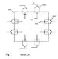
- FIG. 1It comprises a planar radiating element 110 with two openings, such as openings 111 and 112 , at each side of the element, extending from the edge of the element towards the center area thereof.
- an electronic switchis connected which, when conducting, shorts the opening in question at a certain point.
- switch SW 1can be used to short-circuit opening 111 relatively near the mouth of the opening
- switch SW 2can be used to short-circuit opening 112 approximately at the middle of the opening.
- Changing the state of a switchchanges the electrical dimensions of the radiating element and, thereby, its resonance frequency.
- Each switchis controlled with a control signal of its own, such as C 1 for switch SW 1 , so the antenna can be adjusted at relatively small steps.
- the disadvantage of this solutionis the extra cost caused by the quantity of switch components and their mounting.
- the object of the inventionis to realize the electrical adjustment of an antenna in a novel means which alleviates said disadvantages of the prior art.
- An antenna structure according to the inventionis characterized by that which is specified in the independent claim 1 .
- the basic idea of the inventionis as follows:
- the radiating element of an antenna or a part thereofis manufactured from a strongly magnetostrictive material.
- the antennais equipped with at least one electromagnet by means of which a magnetic field can be generated into the magnetostrictive material. This will cause the radiating element to grow in a certain dimension, thus reducing the resonance frequency of the antenna.
- the adjustment of the resonance frequencycan be realized either as two-step or continuous.
- An advantage of the inventionis that an antenna according to it can be adjusted electrically without adding any component in the antenna itself. This brings the additional advantage that the adjustment is reliable since there cannot occur component or switching faults in the operation of the apparatus. Another advantage of the invention is that the manufacturing costs of an antenna according to the invention are smaller than those of prior-art adjustable antennas.
- FIG. 1shows an example of a prior-art adjustable antenna structure
- FIGS. 2 a,bshow an example of an adjustable antenna structure according to the invention
- FIG. 3shows a second example of an adjustable antenna structure according to the invention
- FIG. 4shows a third example of an adjustable antenna structure according to the invention
- FIG. 5shows an example of an apparatus equipped with an antenna according to the invention.
- the antenna structure 200shown in longitudinal section, comprises a radiating monopole element 210 the length of which corresponds to a quarter of the wavelength at the operating frequency, and a winding 220 which constitutes an electromagnet.
- the antenna structurecomprises the frame GND of the radio apparatus in question, serving as a ground plane, to which the radiating element 210 is fastened through an insulating element 240 .
- the radiating elementis connected at its lower end to the antenna port of the radio apparatus through a feed conductor 230 .
- the structureis protected by a hood 250 , drawn in broken line.
- the cylindrical winding 220is round the lower part of the monopole element 210 .
- the current I through the winding 220is zero and, therefore, there is no magnetic field generated by the winding.
- the monopole elementhas a certain electrical length l.
- a certain direct current I 1is led into the winding 220 .
- the direct currentcauses in the winding 220 a magnetic flux ⁇ the majority of which travels through the monopole element in its longitudinal direction and then goes around the winding by the outside, forming a closed path.
- the monopole element 210is advantageously made from a magnetically controlled shape memory (MSM) material. It is divided in the longitudinal direction of the monopole into elementary layers so that in every second elementary layer the internal magnetic moments are arranged substantially in the longitudinal direction of the monopole, i.e. along the axis of the monopole. In every other elementary layer, on the other hand, the magnetic moments are also arranged parallely, but forming a significant angle relative to the longitudinal direction of the monopole element. If the magnetic field strength corresponding to the external magnetic flux ⁇ is sufficient, it will turn the crystal structures of the latter elementary layers such that the magnetic moments throughout the whole element will be parallel to the direction of the axis of the monopole element.
- MCMmagnetically controlled shape memory
- the length of the monopole elementwill increase as the internal zigzag structure of the material will “straighten out”.
- This changemay also be arranged so as to be gradual by increasing the external magnetic field strength gradually. When the external magnetic field is removed, the material will return to the initial state and the monopole element will thus retain its original length.
- the magnetic field of the winding 220has resulted in an increase ⁇ l in the electrical length 1 of the monopole element.
- the relative increase ⁇ l/lmay be e.g. 5%. If the antenna is specified in the rest position to function e.g. in the WCDMA system, a good 5-per-cent adjustment range is enough to shift the operating band into the GSM1900 or GSM1800 system band. Similarly it is possible to shift from the GSM900-band to the AMPS-band.
- the antenna structure 300comprises a planar radiating element 310 and a ground plane GND parallel thereto.
- the feed conductor 301 of the antennais connected to a point F in the radiating element.
- the radiating elementis also connected at a point S to the ground plane via a short-circuit conductor 302 , whereby the antenna is a planar inverted F antenna (PIFA).
- PIFAplanar inverted F antenna
- the radiating elementis supported to the ground plane through insulating elements such as element 305 .
- the structurefurther comprises two electromagnets 321 and 322 formed by cylindrical coils. These are located at a close distance from the radiating plane, below it and at opposing sides.
- a “close distance”means here and in the claims a distance which is shorter than the distance between the radiating plane and ground plane.
- FIG. 4the invention is applied to a dual-band planar antenna.
- the basic antenna structure 400is similar to that shown in FIG. 3 except that now the radiating planar element 410 has a slit 415 the shape of which resembles a rectangular J starting from the edge of the planar element in such a manner that the plane is divided into two branches viewed from the antenna feed point F.
- the first branch B 1follows the edges of the planar element and is clearly longer than the second branch B 2 in the center area of the planar element.
- the antennathus has got two bands.
- the electromagnet 420is in this example a flat winding placed on the second branch B 2 .
- the windingis wound such that the magnetic flux ⁇ caused by the current in the winding travels inside the winding and in the planar element 410 transversely with respect to the longitudinal axis of the second branch.
- the direction of the change in the length of the planar element made from MSM materialis the said transversal direction; thus it deviates by 90 degrees from the direction of the change in the length of the corresponding element in FIG. 3 .
- the portions of the slit 415 at its both sidesbecome narrower. Thereby, the electromagnetic coupling between the first and second branches becomes stronger. This further results in an increase in the electrical lengths of the branches and a decrease in their resonance frequencies.
- the electromagnet 420could also be placed on the slit 415 . In this case, too, there could be several electromagnets. Moreover, they could be placed in the space between the planar element and ground plane.
- FIG. 5shows a mobile station MS comprising an adjustable antenna structure 500 according to the invention.
Landscapes
- Engineering & Computer Science (AREA)
- Computer Networks & Wireless Communication (AREA)
- Variable-Direction Aerials And Aerial Arrays (AREA)
- Details Of Aerials (AREA)
- Waveguide Aerials (AREA)
- Support Of Aerials (AREA)
Abstract
Description
Claims (8)
Applications Claiming Priority (3)
| Application Number | Priority Date | Filing Date | Title |
|---|---|---|---|
| FI20010519 | 2001-03-15 | ||
| FI20010519AFI113218B (en) | 2001-03-15 | 2001-03-15 | Adjustable antenna |
| PCT/FI2002/000201WO2002075845A1 (en) | 2001-03-15 | 2002-03-13 | Adjustable antenna |
Publications (2)
| Publication Number | Publication Date |
|---|---|
| US20040233108A1 US20040233108A1 (en) | 2004-11-25 |
| US6856293B2true US6856293B2 (en) | 2005-02-15 |
Family
ID=8560748
Family Applications (1)
| Application Number | Title | Priority Date | Filing Date |
|---|---|---|---|
| US10/471,189Expired - Fee RelatedUS6856293B2 (en) | 2001-03-15 | 2002-03-13 | Adjustable antenna |
Country Status (7)
| Country | Link |
|---|---|
| US (1) | US6856293B2 (en) |
| EP (1) | EP1380070B1 (en) |
| CN (1) | CN1284272C (en) |
| AT (1) | ATE400071T1 (en) |
| DE (1) | DE60227357D1 (en) |
| FI (1) | FI113218B (en) |
| WO (1) | WO2002075845A1 (en) |
Cited By (33)
| Publication number | Priority date | Publication date | Assignee | Title |
|---|---|---|---|---|
| US20100220016A1 (en)* | 2005-10-03 | 2010-09-02 | Pertti Nissinen | Multiband Antenna System And Methods |
| US20100244978A1 (en)* | 2007-04-19 | 2010-09-30 | Zlatoljub Milosavljevic | Methods and apparatus for matching an antenna |
| US20110156972A1 (en)* | 2009-12-29 | 2011-06-30 | Heikki Korva | Loop resonator apparatus and methods for enhanced field control |
| US8473017B2 (en) | 2005-10-14 | 2013-06-25 | Pulse Finland Oy | Adjustable antenna and methods |
| US8564485B2 (en) | 2005-07-25 | 2013-10-22 | Pulse Finland Oy | Adjustable multiband antenna and methods |
| US20130335280A1 (en)* | 2012-06-13 | 2013-12-19 | Skycross, Inc. | Multimode antenna structures and methods thereof |
| US8618990B2 (en) | 2011-04-13 | 2013-12-31 | Pulse Finland Oy | Wideband antenna and methods |
| US8629813B2 (en) | 2007-08-30 | 2014-01-14 | Pusle Finland Oy | Adjustable multi-band antenna and methods |
| US8648752B2 (en) | 2011-02-11 | 2014-02-11 | Pulse Finland Oy | Chassis-excited antenna apparatus and methods |
| US8866689B2 (en) | 2011-07-07 | 2014-10-21 | Pulse Finland Oy | Multi-band antenna and methods for long term evolution wireless system |
| US8988296B2 (en) | 2012-04-04 | 2015-03-24 | Pulse Finland Oy | Compact polarized antenna and methods |
| US9123990B2 (en) | 2011-10-07 | 2015-09-01 | Pulse Finland Oy | Multi-feed antenna apparatus and methods |
| US9203154B2 (en) | 2011-01-25 | 2015-12-01 | Pulse Finland Oy | Multi-resonance antenna, antenna module, radio device and methods |
| US9246210B2 (en) | 2010-02-18 | 2016-01-26 | Pulse Finland Oy | Antenna with cover radiator and methods |
| US9350081B2 (en) | 2014-01-14 | 2016-05-24 | Pulse Finland Oy | Switchable multi-radiator high band antenna apparatus |
| US9406998B2 (en) | 2010-04-21 | 2016-08-02 | Pulse Finland Oy | Distributed multiband antenna and methods |
| US9450291B2 (en) | 2011-07-25 | 2016-09-20 | Pulse Finland Oy | Multiband slot loop antenna apparatus and methods |
| US9461371B2 (en) | 2009-11-27 | 2016-10-04 | Pulse Finland Oy | MIMO antenna and methods |
| US9484619B2 (en) | 2011-12-21 | 2016-11-01 | Pulse Finland Oy | Switchable diversity antenna apparatus and methods |
| US9531058B2 (en) | 2011-12-20 | 2016-12-27 | Pulse Finland Oy | Loosely-coupled radio antenna apparatus and methods |
| US9590308B2 (en) | 2013-12-03 | 2017-03-07 | Pulse Electronics, Inc. | Reduced surface area antenna apparatus and mobile communications devices incorporating the same |
| US9634383B2 (en) | 2013-06-26 | 2017-04-25 | Pulse Finland Oy | Galvanically separated non-interacting antenna sector apparatus and methods |
| US9647338B2 (en) | 2013-03-11 | 2017-05-09 | Pulse Finland Oy | Coupled antenna structure and methods |
| US9673507B2 (en) | 2011-02-11 | 2017-06-06 | Pulse Finland Oy | Chassis-excited antenna apparatus and methods |
| US9680212B2 (en) | 2013-11-20 | 2017-06-13 | Pulse Finland Oy | Capacitive grounding methods and apparatus for mobile devices |
| US9722308B2 (en) | 2014-08-28 | 2017-08-01 | Pulse Finland Oy | Low passive intermodulation distributed antenna system for multiple-input multiple-output systems and methods of use |
| US9761951B2 (en) | 2009-11-03 | 2017-09-12 | Pulse Finland Oy | Adjustable antenna apparatus and methods |
| US9906260B2 (en) | 2015-07-30 | 2018-02-27 | Pulse Finland Oy | Sensor-based closed loop antenna swapping apparatus and methods |
| US9948002B2 (en) | 2014-08-26 | 2018-04-17 | Pulse Finland Oy | Antenna apparatus with an integrated proximity sensor and methods |
| US9973228B2 (en) | 2014-08-26 | 2018-05-15 | Pulse Finland Oy | Antenna apparatus with an integrated proximity sensor and methods |
| US9979078B2 (en) | 2012-10-25 | 2018-05-22 | Pulse Finland Oy | Modular cell antenna apparatus and methods |
| US10069209B2 (en) | 2012-11-06 | 2018-09-04 | Pulse Finland Oy | Capacitively coupled antenna apparatus and methods |
| US10079428B2 (en) | 2013-03-11 | 2018-09-18 | Pulse Finland Oy | Coupled antenna structure and methods |
Families Citing this family (15)
| Publication number | Priority date | Publication date | Assignee | Title |
|---|---|---|---|---|
| TW563274B (en)* | 2002-10-08 | 2003-11-21 | Wistron Neweb Corp | Dual-band antenna |
| CN101904052B (en) | 2007-12-20 | 2013-04-10 | 原田工业株式会社 | Patch antenna device |
| JP4524318B2 (en)* | 2008-05-27 | 2010-08-18 | 原田工業株式会社 | Automotive noise filter |
| JP5114325B2 (en)* | 2008-07-08 | 2013-01-09 | 原田工業株式会社 | Roof mount antenna device for vehicle |
| JP4832549B2 (en)* | 2009-04-30 | 2011-12-07 | 原田工業株式会社 | Vehicle antenna apparatus using space filling curve |
| JP4955094B2 (en)* | 2009-11-02 | 2012-06-20 | 原田工業株式会社 | Patch antenna |
| US8289043B2 (en) | 2010-03-26 | 2012-10-16 | International Business Machines Corporation | Simulation of printed circuit board impedance variations and crosstalk effects |
| WO2012096355A1 (en) | 2011-01-12 | 2012-07-19 | 原田工業株式会社 | Antenna device |
| JP5274597B2 (en) | 2011-02-15 | 2013-08-28 | 原田工業株式会社 | Vehicle pole antenna |
| USD726696S1 (en) | 2012-09-12 | 2015-04-14 | Harada Industry Co., Ltd. | Vehicle antenna |
| US9520638B2 (en)* | 2013-01-15 | 2016-12-13 | Fitbit, Inc. | Hybrid radio frequency / inductive loop antenna |
| CN103427152B (en)* | 2013-05-15 | 2016-02-17 | 贵州泰格科技有限责任公司 | A kind of resonant antenna of adjustable electric sensibility reciprocal |
| US9196964B2 (en) | 2014-03-05 | 2015-11-24 | Fitbit, Inc. | Hybrid piezoelectric device / radio frequency antenna |
| CN104466413B (en)* | 2014-12-31 | 2017-12-01 | 公安部第三研究所 | The antenna of adjustable gain is realized based on structurally variable filler |
| CN114300834B (en)* | 2022-01-06 | 2022-08-26 | 北京航空航天大学 | Mining miniaturized low-frequency emergency transmission node based on shape memory structure |
Citations (9)
| Publication number | Priority date | Publication date | Assignee | Title |
|---|---|---|---|---|
| US3811128A (en)* | 1973-04-17 | 1974-05-14 | Ball Brothers Res Corp | Electrically scanned microstrip antenna |
| US4751513A (en) | 1986-05-02 | 1988-06-14 | Rca Corporation | Light controlled antennas |
| US5327148A (en)* | 1993-02-17 | 1994-07-05 | Northeastern University | Ferrite microstrip antenna |
| US5589842A (en) | 1991-05-03 | 1996-12-31 | Georgia Tech Research Corporation | Compact microstrip antenna with magnetic substrate |
| EP0884707A1 (en) | 1997-06-13 | 1998-12-16 | Matsushita Electric Industrial Co., Ltd. | Apparatus for detecting magnetostrictive resonator and traffic system |
| EP0899702A2 (en) | 1997-08-29 | 1999-03-03 | Matsushita Electric Industrial Co., Ltd | Magnetostrictive resonator, road in which the resonator is buried and method of buring the resonator |
| US5982335A (en)* | 1997-09-25 | 1999-11-09 | Motorola, Inc. | Antenna with low reluctance material positioned to influence radiation pattern |
| US6292143B1 (en) | 2000-05-04 | 2001-09-18 | The United States Of America As Represented By The Administrator Of The National Aeronautics And Space Administration | Multi-mode broadband patch antenna |
| US6791496B1 (en)* | 2003-03-31 | 2004-09-14 | Harris Corporation | High efficiency slot fed microstrip antenna having an improved stub |
Family Cites Families (1)
| Publication number | Priority date | Publication date | Assignee | Title |
|---|---|---|---|---|
| JPH08242118A (en) | 1995-03-06 | 1996-09-17 | Sony Corp | Planar antenna, its resonance frequency control method and radio communication equipment |
- 2001
- 2001-03-15FIFI20010519Apatent/FI113218B/ennot_activeIP Right Cessation
- 2002
- 2002-03-13WOPCT/FI2002/000201patent/WO2002075845A1/enactiveIP Right Grant
- 2002-03-13EPEP02704781Apatent/EP1380070B1/ennot_activeExpired - Lifetime
- 2002-03-13CNCN02806524.7Apatent/CN1284272C/ennot_activeExpired - Fee Related
- 2002-03-13DEDE60227357Tpatent/DE60227357D1/ennot_activeExpired - Lifetime
- 2002-03-13USUS10/471,189patent/US6856293B2/ennot_activeExpired - Fee Related
- 2002-03-13ATAT02704781Tpatent/ATE400071T1/ennot_activeIP Right Cessation
Patent Citations (9)
| Publication number | Priority date | Publication date | Assignee | Title |
|---|---|---|---|---|
| US3811128A (en)* | 1973-04-17 | 1974-05-14 | Ball Brothers Res Corp | Electrically scanned microstrip antenna |
| US4751513A (en) | 1986-05-02 | 1988-06-14 | Rca Corporation | Light controlled antennas |
| US5589842A (en) | 1991-05-03 | 1996-12-31 | Georgia Tech Research Corporation | Compact microstrip antenna with magnetic substrate |
| US5327148A (en)* | 1993-02-17 | 1994-07-05 | Northeastern University | Ferrite microstrip antenna |
| EP0884707A1 (en) | 1997-06-13 | 1998-12-16 | Matsushita Electric Industrial Co., Ltd. | Apparatus for detecting magnetostrictive resonator and traffic system |
| EP0899702A2 (en) | 1997-08-29 | 1999-03-03 | Matsushita Electric Industrial Co., Ltd | Magnetostrictive resonator, road in which the resonator is buried and method of buring the resonator |
| US5982335A (en)* | 1997-09-25 | 1999-11-09 | Motorola, Inc. | Antenna with low reluctance material positioned to influence radiation pattern |
| US6292143B1 (en) | 2000-05-04 | 2001-09-18 | The United States Of America As Represented By The Administrator Of The National Aeronautics And Space Administration | Multi-mode broadband patch antenna |
| US6791496B1 (en)* | 2003-03-31 | 2004-09-14 | Harris Corporation | High efficiency slot fed microstrip antenna having an improved stub |
Non-Patent Citations (1)
| Title |
|---|
| P.J. Rainville and F.J. Harackiewicz, "Magnetic Tuning of a Microtrip Patch Antenna Fabricated on a Ferrite Film", IEEE Microwave and Guided Wave Letters, vol. 2, No. 12, Dec. 1992. pp. 483-485. |
Cited By (39)
| Publication number | Priority date | Publication date | Assignee | Title |
|---|---|---|---|---|
| US8564485B2 (en) | 2005-07-25 | 2013-10-22 | Pulse Finland Oy | Adjustable multiband antenna and methods |
| US8786499B2 (en) | 2005-10-03 | 2014-07-22 | Pulse Finland Oy | Multiband antenna system and methods |
| US20100220016A1 (en)* | 2005-10-03 | 2010-09-02 | Pertti Nissinen | Multiband Antenna System And Methods |
| US8473017B2 (en) | 2005-10-14 | 2013-06-25 | Pulse Finland Oy | Adjustable antenna and methods |
| US8466756B2 (en) | 2007-04-19 | 2013-06-18 | Pulse Finland Oy | Methods and apparatus for matching an antenna |
| US20100244978A1 (en)* | 2007-04-19 | 2010-09-30 | Zlatoljub Milosavljevic | Methods and apparatus for matching an antenna |
| US8629813B2 (en) | 2007-08-30 | 2014-01-14 | Pusle Finland Oy | Adjustable multi-band antenna and methods |
| US9761951B2 (en) | 2009-11-03 | 2017-09-12 | Pulse Finland Oy | Adjustable antenna apparatus and methods |
| US9461371B2 (en) | 2009-11-27 | 2016-10-04 | Pulse Finland Oy | MIMO antenna and methods |
| US20110156972A1 (en)* | 2009-12-29 | 2011-06-30 | Heikki Korva | Loop resonator apparatus and methods for enhanced field control |
| US8847833B2 (en) | 2009-12-29 | 2014-09-30 | Pulse Finland Oy | Loop resonator apparatus and methods for enhanced field control |
| US9246210B2 (en) | 2010-02-18 | 2016-01-26 | Pulse Finland Oy | Antenna with cover radiator and methods |
| US9406998B2 (en) | 2010-04-21 | 2016-08-02 | Pulse Finland Oy | Distributed multiband antenna and methods |
| US9203154B2 (en) | 2011-01-25 | 2015-12-01 | Pulse Finland Oy | Multi-resonance antenna, antenna module, radio device and methods |
| US8648752B2 (en) | 2011-02-11 | 2014-02-11 | Pulse Finland Oy | Chassis-excited antenna apparatus and methods |
| US9917346B2 (en) | 2011-02-11 | 2018-03-13 | Pulse Finland Oy | Chassis-excited antenna apparatus and methods |
| US9673507B2 (en) | 2011-02-11 | 2017-06-06 | Pulse Finland Oy | Chassis-excited antenna apparatus and methods |
| US8618990B2 (en) | 2011-04-13 | 2013-12-31 | Pulse Finland Oy | Wideband antenna and methods |
| US8866689B2 (en) | 2011-07-07 | 2014-10-21 | Pulse Finland Oy | Multi-band antenna and methods for long term evolution wireless system |
| US9450291B2 (en) | 2011-07-25 | 2016-09-20 | Pulse Finland Oy | Multiband slot loop antenna apparatus and methods |
| US9123990B2 (en) | 2011-10-07 | 2015-09-01 | Pulse Finland Oy | Multi-feed antenna apparatus and methods |
| US9531058B2 (en) | 2011-12-20 | 2016-12-27 | Pulse Finland Oy | Loosely-coupled radio antenna apparatus and methods |
| US9484619B2 (en) | 2011-12-21 | 2016-11-01 | Pulse Finland Oy | Switchable diversity antenna apparatus and methods |
| US9509054B2 (en) | 2012-04-04 | 2016-11-29 | Pulse Finland Oy | Compact polarized antenna and methods |
| US8988296B2 (en) | 2012-04-04 | 2015-03-24 | Pulse Finland Oy | Compact polarized antenna and methods |
| US10096910B2 (en)* | 2012-06-13 | 2018-10-09 | Skycross Co., Ltd. | Multimode antenna structures and methods thereof |
| US20130335280A1 (en)* | 2012-06-13 | 2013-12-19 | Skycross, Inc. | Multimode antenna structures and methods thereof |
| US9979078B2 (en) | 2012-10-25 | 2018-05-22 | Pulse Finland Oy | Modular cell antenna apparatus and methods |
| US10069209B2 (en) | 2012-11-06 | 2018-09-04 | Pulse Finland Oy | Capacitively coupled antenna apparatus and methods |
| US9647338B2 (en) | 2013-03-11 | 2017-05-09 | Pulse Finland Oy | Coupled antenna structure and methods |
| US10079428B2 (en) | 2013-03-11 | 2018-09-18 | Pulse Finland Oy | Coupled antenna structure and methods |
| US9634383B2 (en) | 2013-06-26 | 2017-04-25 | Pulse Finland Oy | Galvanically separated non-interacting antenna sector apparatus and methods |
| US9680212B2 (en) | 2013-11-20 | 2017-06-13 | Pulse Finland Oy | Capacitive grounding methods and apparatus for mobile devices |
| US9590308B2 (en) | 2013-12-03 | 2017-03-07 | Pulse Electronics, Inc. | Reduced surface area antenna apparatus and mobile communications devices incorporating the same |
| US9350081B2 (en) | 2014-01-14 | 2016-05-24 | Pulse Finland Oy | Switchable multi-radiator high band antenna apparatus |
| US9973228B2 (en) | 2014-08-26 | 2018-05-15 | Pulse Finland Oy | Antenna apparatus with an integrated proximity sensor and methods |
| US9948002B2 (en) | 2014-08-26 | 2018-04-17 | Pulse Finland Oy | Antenna apparatus with an integrated proximity sensor and methods |
| US9722308B2 (en) | 2014-08-28 | 2017-08-01 | Pulse Finland Oy | Low passive intermodulation distributed antenna system for multiple-input multiple-output systems and methods of use |
| US9906260B2 (en) | 2015-07-30 | 2018-02-27 | Pulse Finland Oy | Sensor-based closed loop antenna swapping apparatus and methods |
Also Published As
| Publication number | Publication date |
|---|---|
| WO2002075845A1 (en) | 2002-09-26 |
| CN1502144A (en) | 2004-06-02 |
| FI20010519L (en) | 2002-09-16 |
| DE60227357D1 (en) | 2008-08-14 |
| FI113218B (en) | 2004-03-15 |
| FI20010519A0 (en) | 2001-03-15 |
| CN1284272C (en) | 2006-11-08 |
| ATE400071T1 (en) | 2008-07-15 |
| EP1380070A1 (en) | 2004-01-14 |
| EP1380070B1 (en) | 2008-07-02 |
| US20040233108A1 (en) | 2004-11-25 |
Similar Documents
| Publication | Publication Date | Title |
|---|---|---|
| US6856293B2 (en) | Adjustable antenna | |
| US9761951B2 (en) | Adjustable antenna apparatus and methods | |
| KR100627764B1 (en) | Printed Twin Spiral Dual Band Antenna | |
| KR100992919B1 (en) | Adjustable Multiband Antenna | |
| KR101091794B1 (en) | Internal multi-band antenna | |
| KR100612798B1 (en) | Miniature Printed Spiral Antenna for Mobile Terminal | |
| KR100882157B1 (en) | Multiband Antennas & Communication Devices | |
| KR101194227B1 (en) | Adjustable multiband antenna | |
| US8629813B2 (en) | Adjustable multi-band antenna and methods | |
| KR100533624B1 (en) | Multi band chip antenna with dual feeding port, and mobile communication apparatus using the same | |
| JP5009240B2 (en) | Multiband antenna and wireless communication terminal | |
| KR20070052292A (en) | Antenna device and portable wireless communication device including such antenna device | |
| CA2525010A1 (en) | Open-ended slotted pifa antenna and tuning method | |
| CN113078449B (en) | Antenna structure and wireless communication device with same | |
| US8362957B2 (en) | Radiation pattern control | |
| JP2005167730A (en) | Multi-frequency antenna and information terminal device having the same | |
| KR20180094636A (en) | Antenna apparatus | |
| CN113078444A (en) | Antenna structure and wireless communication device with same | |
| CN113078445A (en) | Antenna structure and wireless communication device with same | |
| WO2009082175A2 (en) | Antenna device | |
| KR101480561B1 (en) | Antenna | |
| KR20110066838A (en) | Antenna device |
Legal Events
| Date | Code | Title | Description |
|---|---|---|---|
| AS | Assignment | Owner name:FILTRONIC LK OY, FINLAND Free format text:ASSIGNMENT OF ASSIGNORS INTEREST;ASSIGNOR:BORDI, MIKA;REEL/FRAME:014941/0415 Effective date:20030818 | |
| AS | Assignment | Owner name:LK PRODUCTS OY, FINLAND Free format text:ASSIGNMENT OF ASSIGNORS INTEREST;ASSIGNOR:FILTRONIC LK OY;REEL/FRAME:016662/0450 Effective date:20050808 | |
| AS | Assignment | Owner name:PULSE FINLAND OY, FINLAND Free format text:CHANGE OF NAME;ASSIGNOR:LK PRODUCTS OY;REEL/FRAME:018420/0713 Effective date:20060901 | |
| FPAY | Fee payment | Year of fee payment:4 | |
| REMI | Maintenance fee reminder mailed | ||
| LAPS | Lapse for failure to pay maintenance fees | ||
| STCH | Information on status: patent discontinuation | Free format text:PATENT EXPIRED DUE TO NONPAYMENT OF MAINTENANCE FEES UNDER 37 CFR 1.362 | |
| FP | Lapsed due to failure to pay maintenance fee | Effective date:20130215 | |
| AS | Assignment | Owner name:CANTOR FITZGERALD SECURITIES, NEW YORK Free format text:NOTICE OF SUBSTITUTION OF ADMINISTRATIVE AGENT IN TRADEMARKS AND PATENTS;ASSIGNOR:JPMORGAN CHASE BANK, N.A.;REEL/FRAME:031898/0476 Effective date:20131030 |