US6856102B1 - Three-stage electronic ballast for metal halide lamps - Google Patents
Three-stage electronic ballast for metal halide lampsDownload PDFInfo
- Publication number
- US6856102B1 US6856102B1US10/845,174US84517404AUS6856102B1US 6856102 B1US6856102 B1US 6856102B1US 84517404 AUS84517404 AUS 84517404AUS 6856102 B1US6856102 B1US 6856102B1
- Authority
- US
- United States
- Prior art keywords
- metal halide
- converter
- down converter
- electronic ballast
- current
- Prior art date
- Legal status (The legal status is an assumption and is not a legal conclusion. Google has not performed a legal analysis and makes no representation as to the accuracy of the status listed.)
- Expired - Fee Related
Links
- 229910001507metal halideInorganic materials0.000titleclaimsabstractdescription37
- 150000005309metal halidesChemical class0.000titleclaimsabstractdescription37
- 230000002708enhancing effectEffects0.000claimsabstractdescription5
- 239000003990capacitorSubstances0.000claimsdescription11
- 238000007599dischargingMethods0.000claimsdescription4
- 230000003247decreasing effectEffects0.000claimsdescription2
- 230000000087stabilizing effectEffects0.000claims1
- 230000006870functionEffects0.000abstractdescription3
- 230000009993protective functionEffects0.000abstractdescription2
- 238000010586diagramMethods0.000description7
- 238000005286illuminationMethods0.000description2
- 238000004146energy storageMethods0.000description1
- 230000009191jumpingEffects0.000description1
- 238000012986modificationMethods0.000description1
- 230000004048modificationEffects0.000description1
Images


Classifications
- H—ELECTRICITY
- H05—ELECTRIC TECHNIQUES NOT OTHERWISE PROVIDED FOR
- H05B—ELECTRIC HEATING; ELECTRIC LIGHT SOURCES NOT OTHERWISE PROVIDED FOR; CIRCUIT ARRANGEMENTS FOR ELECTRIC LIGHT SOURCES, IN GENERAL
- H05B41/00—Circuit arrangements or apparatus for igniting or operating discharge lamps
- H05B41/14—Circuit arrangements
- H05B41/26—Circuit arrangements in which the lamp is fed by power derived from DC by means of a converter, e.g. by high-voltage DC
- H05B41/28—Circuit arrangements in which the lamp is fed by power derived from DC by means of a converter, e.g. by high-voltage DC using static converters
- H05B41/288—Circuit arrangements in which the lamp is fed by power derived from DC by means of a converter, e.g. by high-voltage DC using static converters with semiconductor devices and specially adapted for lamps without preheating electrodes, e.g. for high-intensity discharge lamps, high-pressure mercury or sodium lamps or low-pressure sodium lamps
- H05B41/2885—Static converters especially adapted therefor; Control thereof
- H05B41/2886—Static converters especially adapted therefor; Control thereof comprising a controllable preconditioner, e.g. a booster
Definitions
- the present inventionrelates to electronic ballasts for metal halide lamps, and more particularly to an electronic ballast for metal halide lamps having a three-stage structure.
- the three-stage electronic ballast for metal halide lampsmainly comprises a step-up converter, a step-down converter and a full-bridge DC-AC converter, wherein the step-down converter operates an inductor in a continuous boundary current mode to achieve reducing power loss and enhancing efficiency. Equipped with a micro processor, the electronic ballast further possesses the function of power regulation.
- the electronic ballastcan be added with various protective functions without complex control circuits and sensing elements, thereby becoming a high-quality and low-cost electronic ballast for metal halide lamps.
- High-intensity gas-discharging lampsare widely used as light sources for indoor or outdoor illumination. Given its intensity, efficiency, duration and color, metal halide lamps have been used in department stores, supermarkets or in advertisement boards for providing high quality illumination.
- the majority of the electronic ballasts for metal halide lamps of the prior artinclude a power factor correction circuit made of a step-up converter, a DC—DC step-down converter, a full-bridge DC-AC converter and an ignition circuit.
- circuitry structure of the prior artis similar to the three-state structure according to the present invention, its step-down converter is operated in a discontinuous current mode to lessen running down of switching elements. Because of appreciable variation in the characteristic of a metal halide lamp over running time and different manufacturers, it requires a wider design margin for operating the inductor of a step-down converter in discontinuous current mode. This results in high peak values of the inductor currents and therefore high power loss in the circuit. And, consequently, the electronic ballasts of the prior art have step-down converter of low efficiency and high operating temperature, which makes the electronic ballasts less durable.
- the present inventiondiscloses a three-stage electronic ballast for supplying steady power source for a metal halide lamp.
- the electronic ballastcomprises a power factor correction circuit including a step-up converter, a DC step-down converter, a full-bridge DC-AC converter and a high-voltage ignition circuit.
- the three-stage electronic ballast for metal halide lampshas the advantage of reducing power loss and enhancing efficiency, thereby increasing the duration of the electronic ballast.
- the primary objective of the present inventionis to provide a three-stage electronic ballast for metal halide lamps wherein the inductor of the step-down converter is operated in a continuous boundary current mode for enhancing work efficiency and reducing power loss.
- the secondary objective of the present inventionis to provide a three-stage electronic ballast for metal halide lamps capable of dealing with the variation in the characteristics of metal halide lamps due to different manufacturers and providing the metal halide lamps with a constant power.
- the present inventionprovide a three-stage electronic ballast for metal halide lamps.
- the devicecomprises a filter and rectification circuit connected to an input voltage source terminal for suppressing electromagnetic disturbances and rectifying an input voltage signal; a step-up converter disposed after the filter and rectification circuit, the step-up converter further comprising a push-pull transistor, a step-up inductor and a rectification diode and a filter capacitor; a step-down converter disposed after the step-up converter, the step-down converter further comprising an inductor, a diode, a capacitor and a transistor switch, the step-down converter controlling the current in the inductor at the boundary of continuity and discontinuity so as to lessen power loss and enhance operation efficiency; a DC-AC converter disposed after the step-down converter for providing an alternating square-wave voltage to a metal halide lamp; an ignition circuit using circuit elements including a step-up transformer and a capacitor to generate an electric voltage up to 3 kilo volts for dischar
- FIG. 1is a circuitry diagram according to the present invention.
- FIG. 2is a wave diagram of the current through the step-up inductor in the preferred embodiment disclosed in FIG. 1 .
- FIG. 3is a local enlarged wave diagram of the current through the step-up inductor in the preferred embodiment disclosed in FIG. 1 .
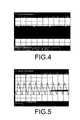
- FIG. 4is a wave diagram of the current through the step-down inductor in the preferred embodiment disclosed in FIG. 1 .
- FIG. 5is a local enlarged wave diagram of the current through the step-down inductor in the preferred embodiment disclosed in FIG. 1 .
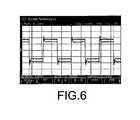
- FIG. 6is a wave diagram of the voltage and the current of the metal halide lamp in the preferred embodiment disclosed in FIG. 1 .
- a circuitry diagramutilizes a filter and rectification circuit 10 to filter and rectify an input commercial electric voltage Vi for suppressing electromagnetic disturbances.
- the voltage signalis then amplified by a step-up converter 20 and supplied to a step-down converter 30 for current control.
- the step-down converter 30comprises a transistor switch Qb, a diode Db, an inductor Lb, a capacitor Cb and resistors R 1 , R 2 .
- a full-bridge DC-AC converter 40is disposed after the step-down converter 30 , which further includes transistor switches Q 3 , Q 4 , Q 5 and Q 6 .
- a high-voltage ignition circuit 50in series connection with a metal halide lamp 60 , is disposed at the AC output terminal of the full-bridge DC-AC converter 40 for discharging the metal halide lamp 60 .
- the principle of the circuitry according to the present inventionis specified as follows.
- a commercial electric voltage Viis applied to a filter circuit consisting of an inductor Lm and a capacitor Cm and then further rectified with a full-wave rectifier Dr.
- the step-up converter 20uses a transistor switch Q 1 for operating an inductor L 1 in a continuous boundary conductive mode by charging the inductor L 1 alternatively, thereby producing a DC potential difference across two terminals of a capacitor Cdc that is higher than the peak value of the input voltage signal.
- the DC voltageis controlled by a step-down converter 30 consisting of a transistor switch Qb, an inductor Lb, a diode Db and a capacitor Cb for providing a steady current to the metal halide lamp 60 .
- the energy-storage inductor Lbis operated in a continuous boundary current mode for lessening the power loss by the transistor switch Qb, as shown in FIGS. 4 and 5 .
- the steady current from the step-down converter 30is processed through the full-bridge DC-AC converter 40 that comprises transistor switches Q 3 , Q 4 , Q 5 and Q 6 for generating an AC current.
- the AC currentactivates a steady alternating voltage having a square wave form across two terminals of the metal halide lamp 60 , as shown in FIG. 6 .
- the high-voltage ignition circuit 50uses circuit elements including a step-up transformer and a capacitor to produce a high electric voltage more than 3 kV to discharge a metal halide lamp.
- the micro processor 70controls the conducting rate of the transistor switch Qb according to the voltages across the resistors R 1 , R 2 , achieving the function of power regulation.
- the electronic ballasts for metal halide lamps of the prior artuse a power-factor correction circuit comprising a step-up converter for jumping input voltage and correcting the power factor at the same time.
- micro processors for specific purposescan be used to operate a step-up converter in the continuous boundary current mode, which can maintain a fixed DC output voltage under large variations in input voltage.
- the present inventionutilizes the same micro processor controlling the power factor circuits for controlling the switch of a step-down converter. Since the micro processors are common and cheap in the market, the present invention is advantageous in low production cost and low complexity.
Landscapes
- Circuit Arrangements For Discharge Lamps (AREA)
Abstract
Description
1. Field of the Invention
The present invention relates to electronic ballasts for metal halide lamps, and more particularly to an electronic ballast for metal halide lamps having a three-stage structure. The three-stage electronic ballast for metal halide lamps mainly comprises a step-up converter, a step-down converter and a full-bridge DC-AC converter, wherein the step-down converter operates an inductor in a continuous boundary current mode to achieve reducing power loss and enhancing efficiency. Equipped with a micro processor, the electronic ballast further possesses the function of power regulation. The electronic ballast can be added with various protective functions without complex control circuits and sensing elements, thereby becoming a high-quality and low-cost electronic ballast for metal halide lamps.
2. Description of the Prior Art
High-intensity gas-discharging lamps are widely used as light sources for indoor or outdoor illumination. Given its intensity, efficiency, duration and color, metal halide lamps have been used in department stores, supermarkets or in advertisement boards for providing high quality illumination.
The majority of the electronic ballasts for metal halide lamps of the prior art include a power factor correction circuit made of a step-up converter, a DC—DC step-down converter, a full-bridge DC-AC converter and an ignition circuit. Although circuitry structure of the prior art is similar to the three-state structure according to the present invention, its step-down converter is operated in a discontinuous current mode to lessen running down of switching elements. Because of appreciable variation in the characteristic of a metal halide lamp over running time and different manufacturers, it requires a wider design margin for operating the inductor of a step-down converter in discontinuous current mode. This results in high peak values of the inductor currents and therefore high power loss in the circuit. And, consequently, the electronic ballasts of the prior art have step-down converter of low efficiency and high operating temperature, which makes the electronic ballasts less durable.
Accordingly, the present invention discloses a three-stage electronic ballast for supplying steady power source for a metal halide lamp. The electronic ballast comprises a power factor correction circuit including a step-up converter, a DC step-down converter, a full-bridge DC-AC converter and a high-voltage ignition circuit. The three-stage electronic ballast for metal halide lamps has the advantage of reducing power loss and enhancing efficiency, thereby increasing the duration of the electronic ballast.
Therefore, the primary objective of the present invention is to provide a three-stage electronic ballast for metal halide lamps wherein the inductor of the step-down converter is operated in a continuous boundary current mode for enhancing work efficiency and reducing power loss.
The secondary objective of the present invention is to provide a three-stage electronic ballast for metal halide lamps capable of dealing with the variation in the characteristics of metal halide lamps due to different manufacturers and providing the metal halide lamps with a constant power.
To achieve above object, the present invention provide a three-stage electronic ballast for metal halide lamps. The device comprises a filter and rectification circuit connected to an input voltage source terminal for suppressing electromagnetic disturbances and rectifying an input voltage signal; a step-up converter disposed after the filter and rectification circuit, the step-up converter further comprising a push-pull transistor, a step-up inductor and a rectification diode and a filter capacitor; a step-down converter disposed after the step-up converter, the step-down converter further comprising an inductor, a diode, a capacitor and a transistor switch, the step-down converter controlling the current in the inductor at the boundary of continuity and discontinuity so as to lessen power loss and enhance operation efficiency; a DC-AC converter disposed after the step-down converter for providing an alternating square-wave voltage to a metal halide lamp; an ignition circuit using circuit elements including a step-up transformer and a capacitor to generate an electric voltage up to 3 kilo volts for discharging the metal halide lamp; and a micro processor for controlling the conducting rate of the step-down converter according to the product of output voltage and current of the step-down converter, whereby power regulation can be achieved; The three-stage electronic ballast for metal halide lamps can force the inductor in the step-down converter to operate in a continuous boundary current mode, whereby the peak value of the inductor current will be decreased, and whereby the transistor switch switches under zero current, significantly reducing power loss in switching.
The various objects and advantages of the present invention will be more readily understood from the following detailed description when read in conjunction with the appended drawings.
Referring toFIG. 1 , a circuitry diagram according to the present invention utilizes a filter andrectification circuit 10 to filter and rectify an input commercial electric voltage Vi for suppressing electromagnetic disturbances. The voltage signal is then amplified by a step-up converter 20 and supplied to a step-down converter 30 for current control. The step-down converter 30 comprises a transistor switch Qb, a diode Db, an inductor Lb, a capacitor Cb and resistors R1, R2. A full-bridge DC-AC converter 40 is disposed after the step-down converter 30, which further includes transistor switches Q3, Q4, Q5 and Q6. A high-voltage ignition circuit 50, in series connection with ametal halide lamp 60, is disposed at the AC output terminal of the full-bridge DC-AC converter 40 for discharging themetal halide lamp 60.
Referring toFIGS. 1 and 2 , the principle of the circuitry according to the present invention is specified as follows. A commercial electric voltage Vi is applied to a filter circuit consisting of an inductor Lm and a capacitor Cm and then further rectified with a full-wave rectifier Dr. The step-up converter 20 uses a transistor switch Q1 for operating an inductor L1 in a continuous boundary conductive mode by charging the inductor L1 alternatively, thereby producing a DC potential difference across two terminals of a capacitor Cdc that is higher than the peak value of the input voltage signal. The DC voltage is controlled by a step-down converter 30 consisting of a transistor switch Qb, an inductor Lb, a diode Db and a capacitor Cb for providing a steady current to themetal halide lamp 60. The energy-storage inductor Lb is operated in a continuous boundary current mode for lessening the power loss by the transistor switch Qb, as shown inFIGS. 4 and 5 . Finally, the steady current from the step-down converter 30 is processed through the full-bridge DC-AC converter 40 that comprises transistor switches Q3, Q4, Q5 and Q6 for generating an AC current. The AC current activates a steady alternating voltage having a square wave form across two terminals of themetal halide lamp 60, as shown in FIG.6. The high-voltage ignition circuit 50 uses circuit elements including a step-up transformer and a capacitor to produce a high electric voltage more than 3 kV to discharge a metal halide lamp. Themicro processor 70 controls the conducting rate of the transistor switch Qb according to the voltages across the resistors R1, R2, achieving the function of power regulation.
Further, the electronic ballasts for metal halide lamps of the prior art use a power-factor correction circuit comprising a step-up converter for jumping input voltage and correcting the power factor at the same time. micro processors for specific purposes can be used to operate a step-up converter in the continuous boundary current mode, which can maintain a fixed DC output voltage under large variations in input voltage. The present invention utilizes the same micro processor controlling the power factor circuits for controlling the switch of a step-down converter. Since the micro processors are common and cheap in the market, the present invention is advantageous in low production cost and low complexity.
The present invention is thus described, and it will be obvious that the same may be varied in many ways. Such variations are not to be regarded as a departure from the spirit and scope of the present invention, and all such modifications as would be obvious to one skilled in the art are intended to be included within the scope of the following claims.
Claims (3)
1. A three-stage electronic ballast for metal halide lamps, comprising:
a filter and rectification circuit connected to an input voltage source terminal for suppressing electromagnetic disturbances and rectifying an input voltage signal;
a step-up converter disposed after said filter and rectification circuit, said step-up converter further comprising a push-pull transistor, a step-up inductor and a rectification diode and a filter capacitor;
a step-down converter disposed after said step-up converter, said step-down converter further comprising an inductor, a diode, a capacitor and a transistor switch, said step-down converter controlling the current in said inductor at the boundary of continuity and discontinuity so as to lessen power loss and enhance operation efficiency;
a DC-AC converter disposed after said step-down converter for providing an alternating square-wave voltage to a metal halide lamp;
an ignition circuit using circuit elements including a step-up transformer and a capacitor to generate an electric voltage up to 3 kilo volts for discharging said metal halide lamp; and
a micro processor for controlling the conducting rate of said step-down converter according to the product of output voltage and current of said step-down converter, whereby power regulation can be achieved;
whereby said three-stage electronic ballast for metal halide lamps can force said inductor in said step-down converter to operate in a continuous boundary current mode, whereby the peak value of said inductor current will be decreased, and whereby said transistor switch switches under zero current, significantly reducing power loss in switching.
2. The three-stage electronic ballast for metal halide lamps ofclaim 1 wherein the output power of said metal halide lamp is calculated and controlled by said micro processor to attain a constant value regardless of the characteristic of said metal halide lamp, and wherein said micro processor automatically turns off said switch of said step-down converter when said metal halide lamp cease to operate for protecting said electronic ballast.
3. The three-stage electronic ballast for metal halide lamps ofclaim 1 wherein said step-up converter and said step-down converter are driven by the same driving integrated circuits; said driving integrated circuit for said step-up converter achieves stabilizing output voltage and enhancing power factor so as to operate the current in said step-up converter at the boundary between continuity and discontinuity; said driving integrated circuit for said step-down converter achieves lessening the peak current value in said switch and operating the current in said step-down converter at the boundary between continuity and discontinuity regardless of the characteristic of said metal halide lamp, thereby lessening the power loss in said step-down converter.
Priority Applications (1)
| Application Number | Priority Date | Filing Date | Title |
|---|---|---|---|
| US10/845,174US6856102B1 (en) | 2004-05-14 | 2004-05-14 | Three-stage electronic ballast for metal halide lamps |
Applications Claiming Priority (1)
| Application Number | Priority Date | Filing Date | Title |
|---|---|---|---|
| US10/845,174US6856102B1 (en) | 2004-05-14 | 2004-05-14 | Three-stage electronic ballast for metal halide lamps |
Publications (1)
| Publication Number | Publication Date |
|---|---|
| US6856102B1true US6856102B1 (en) | 2005-02-15 |
Family
ID=34116948
Family Applications (1)
| Application Number | Title | Priority Date | Filing Date |
|---|---|---|---|
| US10/845,174Expired - Fee RelatedUS6856102B1 (en) | 2004-05-14 | 2004-05-14 | Three-stage electronic ballast for metal halide lamps |
Country Status (1)
| Country | Link |
|---|---|
| US (1) | US6856102B1 (en) |
Cited By (61)
| Publication number | Priority date | Publication date | Assignee | Title |
|---|---|---|---|---|
| US20060113922A1 (en)* | 2004-10-29 | 2006-06-01 | International Rectifier Corporation | HID buck and full-bridge ballast control IC |
| US20090251060A1 (en)* | 2008-03-31 | 2009-10-08 | Nicollet Technologies Corporation | Electronic ballast system with lamp interface network |
| US20090262556A1 (en)* | 2008-04-16 | 2009-10-22 | Kenji Tomiyoshi | H-bridge buck-boost converter |
| US7768215B1 (en) | 2008-06-26 | 2010-08-03 | Universal Lighting Technologies, Inc. | Method and system for controlling transient current signals in an electronic ballast |
| US20110205766A1 (en)* | 2004-11-08 | 2011-08-25 | Cuauhtemoc Rodriguez | Power Conditioning Unit |
| US20110266978A1 (en)* | 2010-04-29 | 2011-11-03 | Osram Sylvania Inc. | Light output control technique by estimating lamp efficacy as a function of temperature and power |
| US8405367B2 (en) | 2006-01-13 | 2013-03-26 | Enecsys Limited | Power conditioning units |
| US8461809B2 (en) | 2006-01-13 | 2013-06-11 | Enecsys Limited | Power conditioning unit |
| US20130181625A1 (en)* | 2012-01-13 | 2013-07-18 | Ching-Tsai Pan | Single stage electronic ballast with power factor correction |
| US20140306677A1 (en)* | 2013-04-12 | 2014-10-16 | Silergy Semiconductor Technology (Hangzhou) Ltd | Current detection circuit and switching regulator thereof |
| US9112379B2 (en) | 2006-12-06 | 2015-08-18 | Solaredge Technologies Ltd. | Pairing of components in a direct current distributed power generation system |
| US9130401B2 (en) | 2006-12-06 | 2015-09-08 | Solaredge Technologies Ltd. | Distributed power harvesting systems using DC power sources |
| US9235228B2 (en) | 2012-03-05 | 2016-01-12 | Solaredge Technologies Ltd. | Direct current link circuit |
| US9291696B2 (en) | 2007-12-05 | 2016-03-22 | Solaredge Technologies Ltd. | Photovoltaic system power tracking method |
| US9318974B2 (en) | 2014-03-26 | 2016-04-19 | Solaredge Technologies Ltd. | Multi-level inverter with flying capacitor topology |
| US9362743B2 (en) | 2008-05-05 | 2016-06-07 | Solaredge Technologies Ltd. | Direct current power combiner |
| US9368964B2 (en) | 2006-12-06 | 2016-06-14 | Solaredge Technologies Ltd. | Distributed power system using direct current power sources |
| US9401599B2 (en) | 2010-12-09 | 2016-07-26 | Solaredge Technologies Ltd. | Disconnection of a string carrying direct current power |
| US9407161B2 (en) | 2007-12-05 | 2016-08-02 | Solaredge Technologies Ltd. | Parallel connected inverters |
| US9537445B2 (en) | 2008-12-04 | 2017-01-03 | Solaredge Technologies Ltd. | Testing of a photovoltaic panel |
| US9543889B2 (en) | 2006-12-06 | 2017-01-10 | Solaredge Technologies Ltd. | Distributed power harvesting systems using DC power sources |
| US9548619B2 (en) | 2013-03-14 | 2017-01-17 | Solaredge Technologies Ltd. | Method and apparatus for storing and depleting energy |
| US9590526B2 (en) | 2006-12-06 | 2017-03-07 | Solaredge Technologies Ltd. | Safety mechanisms, wake up and shutdown methods in distributed power installations |
| US9647442B2 (en) | 2010-11-09 | 2017-05-09 | Solaredge Technologies Ltd. | Arc detection and prevention in a power generation system |
| US9644993B2 (en) | 2006-12-06 | 2017-05-09 | Solaredge Technologies Ltd. | Monitoring of distributed power harvesting systems using DC power sources |
| US9673711B2 (en) | 2007-08-06 | 2017-06-06 | Solaredge Technologies Ltd. | Digital average input current control in power converter |
| US9680304B2 (en) | 2006-12-06 | 2017-06-13 | Solaredge Technologies Ltd. | Method for distributed power harvesting using DC power sources |
| US9812984B2 (en) | 2012-01-30 | 2017-11-07 | Solaredge Technologies Ltd. | Maximizing power in a photovoltaic distributed power system |
| US9819178B2 (en) | 2013-03-15 | 2017-11-14 | Solaredge Technologies Ltd. | Bypass mechanism |
| US9831824B2 (en) | 2007-12-05 | 2017-11-28 | SolareEdge Technologies Ltd. | Current sensing on a MOSFET |
| US9853565B2 (en) | 2012-01-30 | 2017-12-26 | Solaredge Technologies Ltd. | Maximized power in a photovoltaic distributed power system |
| US9853538B2 (en) | 2007-12-04 | 2017-12-26 | Solaredge Technologies Ltd. | Distributed power harvesting systems using DC power sources |
| US9866098B2 (en) | 2011-01-12 | 2018-01-09 | Solaredge Technologies Ltd. | Serially connected inverters |
| US9869701B2 (en) | 2009-05-26 | 2018-01-16 | Solaredge Technologies Ltd. | Theft detection and prevention in a power generation system |
| US9876430B2 (en) | 2008-03-24 | 2018-01-23 | Solaredge Technologies Ltd. | Zero voltage switching |
| US9923516B2 (en) | 2012-01-30 | 2018-03-20 | Solaredge Technologies Ltd. | Photovoltaic panel circuitry |
| US9941813B2 (en) | 2013-03-14 | 2018-04-10 | Solaredge Technologies Ltd. | High frequency multi-level inverter |
| US9939117B1 (en) | 2017-03-10 | 2018-04-10 | Semisilicon Technology Corp. | Light emitting diode system with light signals carried via power lines |
| US9960667B2 (en) | 2006-12-06 | 2018-05-01 | Solaredge Technologies Ltd. | System and method for protection during inverter shutdown in distributed power installations |
| US9966766B2 (en) | 2006-12-06 | 2018-05-08 | Solaredge Technologies Ltd. | Battery power delivery module |
| US10115841B2 (en) | 2012-06-04 | 2018-10-30 | Solaredge Technologies Ltd. | Integrated photovoltaic panel circuitry |
| US10230310B2 (en) | 2016-04-05 | 2019-03-12 | Solaredge Technologies Ltd | Safety switch for photovoltaic systems |
| US10396662B2 (en) | 2011-09-12 | 2019-08-27 | Solaredge Technologies Ltd | Direct current link circuit |
| US10673222B2 (en) | 2010-11-09 | 2020-06-02 | Solaredge Technologies Ltd. | Arc detection and prevention in a power generation system |
| US10673229B2 (en) | 2010-11-09 | 2020-06-02 | Solaredge Technologies Ltd. | Arc detection and prevention in a power generation system |
| US10931119B2 (en) | 2012-01-11 | 2021-02-23 | Solaredge Technologies Ltd. | Photovoltaic module |
| US11018623B2 (en) | 2016-04-05 | 2021-05-25 | Solaredge Technologies Ltd. | Safety switch for photovoltaic systems |
| US11177663B2 (en) | 2016-04-05 | 2021-11-16 | Solaredge Technologies Ltd. | Chain of power devices |
| US11264947B2 (en) | 2007-12-05 | 2022-03-01 | Solaredge Technologies Ltd. | Testing of a photovoltaic panel |
| US11296650B2 (en) | 2006-12-06 | 2022-04-05 | Solaredge Technologies Ltd. | System and method for protection during inverter shutdown in distributed power installations |
| US11309832B2 (en) | 2006-12-06 | 2022-04-19 | Solaredge Technologies Ltd. | Distributed power harvesting systems using DC power sources |
| US11569660B2 (en) | 2006-12-06 | 2023-01-31 | Solaredge Technologies Ltd. | Distributed power harvesting systems using DC power sources |
| US11569659B2 (en) | 2006-12-06 | 2023-01-31 | Solaredge Technologies Ltd. | Distributed power harvesting systems using DC power sources |
| US11687112B2 (en) | 2006-12-06 | 2023-06-27 | Solaredge Technologies Ltd. | Distributed power harvesting systems using DC power sources |
| US11728768B2 (en) | 2006-12-06 | 2023-08-15 | Solaredge Technologies Ltd. | Pairing of components in a direct current distributed power generation system |
| US11735910B2 (en) | 2006-12-06 | 2023-08-22 | Solaredge Technologies Ltd. | Distributed power system using direct current power sources |
| US11855231B2 (en) | 2006-12-06 | 2023-12-26 | Solaredge Technologies Ltd. | Distributed power harvesting systems using DC power sources |
| US11881814B2 (en) | 2005-12-05 | 2024-01-23 | Solaredge Technologies Ltd. | Testing of a photovoltaic panel |
| US11888387B2 (en) | 2006-12-06 | 2024-01-30 | Solaredge Technologies Ltd. | Safety mechanisms, wake up and shutdown methods in distributed power installations |
| US12057807B2 (en) | 2016-04-05 | 2024-08-06 | Solaredge Technologies Ltd. | Chain of power devices |
| US12418177B2 (en) | 2009-10-24 | 2025-09-16 | Solaredge Technologies Ltd. | Distributed power system using direct current power sources |
Citations (3)
| Publication number | Priority date | Publication date | Assignee | Title |
|---|---|---|---|---|
| US5381076A (en)* | 1993-10-18 | 1995-01-10 | General Electric Company | Metal halide electronic ballast |
| US6107754A (en)* | 1999-01-02 | 2000-08-22 | Inlight Co., Ltd. | Electronic ballast for high-intensity discharge lamp and method of driving high-intensity discharge lamp |
| US6188177B1 (en)* | 1998-05-20 | 2001-02-13 | Power Circuit Innovations, Inc. | Light sensing dimming control system for gas discharge lamps |
- 2004
- 2004-05-14USUS10/845,174patent/US6856102B1/ennot_activeExpired - Fee Related
Patent Citations (3)
| Publication number | Priority date | Publication date | Assignee | Title |
|---|---|---|---|---|
| US5381076A (en)* | 1993-10-18 | 1995-01-10 | General Electric Company | Metal halide electronic ballast |
| US6188177B1 (en)* | 1998-05-20 | 2001-02-13 | Power Circuit Innovations, Inc. | Light sensing dimming control system for gas discharge lamps |
| US6107754A (en)* | 1999-01-02 | 2000-08-22 | Inlight Co., Ltd. | Electronic ballast for high-intensity discharge lamp and method of driving high-intensity discharge lamp |
Cited By (177)
| Publication number | Priority date | Publication date | Assignee | Title |
|---|---|---|---|---|
| US20060113922A1 (en)* | 2004-10-29 | 2006-06-01 | International Rectifier Corporation | HID buck and full-bridge ballast control IC |
| US7525256B2 (en)* | 2004-10-29 | 2009-04-28 | International Rectifier Corporation | HID buck and full-bridge ballast control IC |
| US8369113B2 (en)* | 2004-11-08 | 2013-02-05 | Enecsys Limited | Power conditioning unit |
| US9473038B2 (en) | 2004-11-08 | 2016-10-18 | Solarcity Corporation | Power conditioning unit with voltage converters |
| US9831794B2 (en) | 2004-11-08 | 2017-11-28 | Solarcity Corporation | Power conditioning unit with voltage converters |
| US10033292B2 (en) | 2004-11-08 | 2018-07-24 | Solarcity Corporation | Power conditioning unit with voltage converters |
| US20110205766A1 (en)* | 2004-11-08 | 2011-08-25 | Cuauhtemoc Rodriguez | Power Conditioning Unit |
| US8971082B2 (en) | 2004-11-08 | 2015-03-03 | Enecsys Limited | Power conditioning unit with voltage converters |
| US11881814B2 (en) | 2005-12-05 | 2024-01-23 | Solaredge Technologies Ltd. | Testing of a photovoltaic panel |
| US9812980B2 (en) | 2006-01-13 | 2017-11-07 | Solarcity Corporation | Power conditioning units |
| US9812985B2 (en) | 2006-01-13 | 2017-11-07 | Solarcity Corporation | Solar power conditioning unit |
| US8405367B2 (en) | 2006-01-13 | 2013-03-26 | Enecsys Limited | Power conditioning units |
| US8461809B2 (en) | 2006-01-13 | 2013-06-11 | Enecsys Limited | Power conditioning unit |
| US10193467B2 (en) | 2006-01-13 | 2019-01-29 | Tesla, Inc. | Power conditioning units |
| US9270191B2 (en) | 2006-01-13 | 2016-02-23 | Solarcity Corporation | Power condition units with MPPT |
| US8811047B2 (en) | 2006-01-13 | 2014-08-19 | Enecsys Limited | Solar power conditioning unit |
| US9246397B2 (en) | 2006-01-13 | 2016-01-26 | Solarcity Corporation | Solar power conditioning unit |
| US9680304B2 (en) | 2006-12-06 | 2017-06-13 | Solaredge Technologies Ltd. | Method for distributed power harvesting using DC power sources |
| US11594881B2 (en) | 2006-12-06 | 2023-02-28 | Solaredge Technologies Ltd. | Distributed power harvesting systems using DC power sources |
| US9130401B2 (en) | 2006-12-06 | 2015-09-08 | Solaredge Technologies Ltd. | Distributed power harvesting systems using DC power sources |
| US12027849B2 (en) | 2006-12-06 | 2024-07-02 | Solaredge Technologies Ltd. | Distributed power system using direct current power sources |
| US12027970B2 (en) | 2006-12-06 | 2024-07-02 | Solaredge Technologies Ltd. | Safety mechanisms, wake up and shutdown methods in distributed power installations |
| US12032080B2 (en) | 2006-12-06 | 2024-07-09 | Solaredge Technologies Ltd. | Safety mechanisms, wake up and shutdown methods in distributed power installations |
| US11961922B2 (en) | 2006-12-06 | 2024-04-16 | Solaredge Technologies Ltd. | Distributed power harvesting systems using DC power sources |
| US11962243B2 (en) | 2006-12-06 | 2024-04-16 | Solaredge Technologies Ltd. | Method for distributed power harvesting using DC power sources |
| US11888387B2 (en) | 2006-12-06 | 2024-01-30 | Solaredge Technologies Ltd. | Safety mechanisms, wake up and shutdown methods in distributed power installations |
| US9368964B2 (en) | 2006-12-06 | 2016-06-14 | Solaredge Technologies Ltd. | Distributed power system using direct current power sources |
| US12046940B2 (en) | 2006-12-06 | 2024-07-23 | Solaredge Technologies Ltd. | Battery power control |
| US11855231B2 (en) | 2006-12-06 | 2023-12-26 | Solaredge Technologies Ltd. | Distributed power harvesting systems using DC power sources |
| US12068599B2 (en) | 2006-12-06 | 2024-08-20 | Solaredge Technologies Ltd. | System and method for protection during inverter shutdown in distributed power installations |
| US11735910B2 (en) | 2006-12-06 | 2023-08-22 | Solaredge Technologies Ltd. | Distributed power system using direct current power sources |
| US11728768B2 (en) | 2006-12-06 | 2023-08-15 | Solaredge Technologies Ltd. | Pairing of components in a direct current distributed power generation system |
| US9543889B2 (en) | 2006-12-06 | 2017-01-10 | Solaredge Technologies Ltd. | Distributed power harvesting systems using DC power sources |
| US11687112B2 (en) | 2006-12-06 | 2023-06-27 | Solaredge Technologies Ltd. | Distributed power harvesting systems using DC power sources |
| US9590526B2 (en) | 2006-12-06 | 2017-03-07 | Solaredge Technologies Ltd. | Safety mechanisms, wake up and shutdown methods in distributed power installations |
| US11682918B2 (en) | 2006-12-06 | 2023-06-20 | Solaredge Technologies Ltd. | Battery power delivery module |
| US11658482B2 (en) | 2006-12-06 | 2023-05-23 | Solaredge Technologies Ltd. | Distributed power harvesting systems using DC power sources |
| US9644993B2 (en) | 2006-12-06 | 2017-05-09 | Solaredge Technologies Ltd. | Monitoring of distributed power harvesting systems using DC power sources |
| US10637393B2 (en) | 2006-12-06 | 2020-04-28 | Solaredge Technologies Ltd. | Distributed power harvesting systems using DC power sources |
| US10673253B2 (en) | 2006-12-06 | 2020-06-02 | Solaredge Technologies Ltd. | Battery power delivery module |
| US12107417B2 (en) | 2006-12-06 | 2024-10-01 | Solaredge Technologies Ltd. | Distributed power harvesting systems using DC power sources |
| US11598652B2 (en) | 2006-12-06 | 2023-03-07 | Solaredge Technologies Ltd. | Monitoring of distributed power harvesting systems using DC power sources |
| US12224706B2 (en) | 2006-12-06 | 2025-02-11 | Solaredge Technologies Ltd. | Pairing of components in a direct current distributed power generation system |
| US11594882B2 (en) | 2006-12-06 | 2023-02-28 | Solaredge Technologies Ltd. | Distributed power harvesting systems using DC power sources |
| US12276997B2 (en) | 2006-12-06 | 2025-04-15 | Solaredge Technologies Ltd. | Distributed power harvesting systems using DC power sources |
| US12281919B2 (en) | 2006-12-06 | 2025-04-22 | Solaredge Technologies Ltd. | Monitoring of distributed power harvesting systems using DC power sources |
| US9112379B2 (en) | 2006-12-06 | 2015-08-18 | Solaredge Technologies Ltd. | Pairing of components in a direct current distributed power generation system |
| US11002774B2 (en) | 2006-12-06 | 2021-05-11 | Solaredge Technologies Ltd. | Monitoring of distributed power harvesting systems using DC power sources |
| US9853490B2 (en) | 2006-12-06 | 2017-12-26 | Solaredge Technologies Ltd. | Distributed power system using direct current power sources |
| US11031861B2 (en) | 2006-12-06 | 2021-06-08 | Solaredge Technologies Ltd. | System and method for protection during inverter shutdown in distributed power installations |
| US11594880B2 (en) | 2006-12-06 | 2023-02-28 | Solaredge Technologies Ltd. | Distributed power harvesting systems using DC power sources |
| US11579235B2 (en) | 2006-12-06 | 2023-02-14 | Solaredge Technologies Ltd. | Safety mechanisms, wake up and shutdown methods in distributed power installations |
| US11575261B2 (en) | 2006-12-06 | 2023-02-07 | Solaredge Technologies Ltd. | Distributed power harvesting systems using DC power sources |
| US11575260B2 (en) | 2006-12-06 | 2023-02-07 | Solaredge Technologies Ltd. | Distributed power harvesting systems using DC power sources |
| US11569659B2 (en) | 2006-12-06 | 2023-01-31 | Solaredge Technologies Ltd. | Distributed power harvesting systems using DC power sources |
| US11569660B2 (en) | 2006-12-06 | 2023-01-31 | Solaredge Technologies Ltd. | Distributed power harvesting systems using DC power sources |
| US9948233B2 (en) | 2006-12-06 | 2018-04-17 | Solaredge Technologies Ltd. | Distributed power harvesting systems using DC power sources |
| US9960667B2 (en) | 2006-12-06 | 2018-05-01 | Solaredge Technologies Ltd. | System and method for protection during inverter shutdown in distributed power installations |
| US9960731B2 (en) | 2006-12-06 | 2018-05-01 | Solaredge Technologies Ltd. | Pairing of components in a direct current distributed power generation system |
| US9966766B2 (en) | 2006-12-06 | 2018-05-08 | Solaredge Technologies Ltd. | Battery power delivery module |
| US11476799B2 (en) | 2006-12-06 | 2022-10-18 | Solaredge Technologies Ltd. | Distributed power harvesting systems using DC power sources |
| US11309832B2 (en) | 2006-12-06 | 2022-04-19 | Solaredge Technologies Ltd. | Distributed power harvesting systems using DC power sources |
| US12316274B2 (en) | 2006-12-06 | 2025-05-27 | Solaredge Technologies Ltd. | Pairing of components in a direct current distributed power generation system |
| US10097007B2 (en) | 2006-12-06 | 2018-10-09 | Solaredge Technologies Ltd. | Method for distributed power harvesting using DC power sources |
| US11043820B2 (en) | 2006-12-06 | 2021-06-22 | Solaredge Technologies Ltd. | Battery power delivery module |
| US11296650B2 (en) | 2006-12-06 | 2022-04-05 | Solaredge Technologies Ltd. | System and method for protection during inverter shutdown in distributed power installations |
| US12388492B2 (en) | 2006-12-06 | 2025-08-12 | Solaredge Technologies Ltd. | Safety mechanisms, wake up and shutdown methods in distributed power installations |
| US10230245B2 (en) | 2006-12-06 | 2019-03-12 | Solaredge Technologies Ltd | Battery power delivery module |
| US11183922B2 (en) | 2006-12-06 | 2021-11-23 | Solaredge Technologies Ltd. | Distributed power harvesting systems using DC power sources |
| US11073543B2 (en) | 2006-12-06 | 2021-07-27 | Solaredge Technologies Ltd. | Monitoring of distributed power harvesting systems using DC power sources |
| US11063440B2 (en) | 2006-12-06 | 2021-07-13 | Solaredge Technologies Ltd. | Method for distributed power harvesting using DC power sources |
| US10447150B2 (en) | 2006-12-06 | 2019-10-15 | Solaredge Technologies Ltd. | Distributed power harvesting systems using DC power sources |
| US10116217B2 (en) | 2007-08-06 | 2018-10-30 | Solaredge Technologies Ltd. | Digital average input current control in power converter |
| US11594968B2 (en) | 2007-08-06 | 2023-02-28 | Solaredge Technologies Ltd. | Digital average input current control in power converter |
| US10516336B2 (en) | 2007-08-06 | 2019-12-24 | Solaredge Technologies Ltd. | Digital average input current control in power converter |
| US9673711B2 (en) | 2007-08-06 | 2017-06-06 | Solaredge Technologies Ltd. | Digital average input current control in power converter |
| US9853538B2 (en) | 2007-12-04 | 2017-12-26 | Solaredge Technologies Ltd. | Distributed power harvesting systems using DC power sources |
| US9831824B2 (en) | 2007-12-05 | 2017-11-28 | SolareEdge Technologies Ltd. | Current sensing on a MOSFET |
| US12055647B2 (en) | 2007-12-05 | 2024-08-06 | Solaredge Technologies Ltd. | Parallel connected inverters |
| US11693080B2 (en) | 2007-12-05 | 2023-07-04 | Solaredge Technologies Ltd. | Parallel connected inverters |
| US9407161B2 (en) | 2007-12-05 | 2016-08-02 | Solaredge Technologies Ltd. | Parallel connected inverters |
| US10644589B2 (en) | 2007-12-05 | 2020-05-05 | Solaredge Technologies Ltd. | Parallel connected inverters |
| US11183923B2 (en) | 2007-12-05 | 2021-11-23 | Solaredge Technologies Ltd. | Parallel connected inverters |
| US10693415B2 (en) | 2007-12-05 | 2020-06-23 | Solaredge Technologies Ltd. | Testing of a photovoltaic panel |
| US11264947B2 (en) | 2007-12-05 | 2022-03-01 | Solaredge Technologies Ltd. | Testing of a photovoltaic panel |
| US11183969B2 (en) | 2007-12-05 | 2021-11-23 | Solaredge Technologies Ltd. | Testing of a photovoltaic panel |
| US9291696B2 (en) | 2007-12-05 | 2016-03-22 | Solaredge Technologies Ltd. | Photovoltaic system power tracking method |
| US11894806B2 (en) | 2007-12-05 | 2024-02-06 | Solaredge Technologies Ltd. | Testing of a photovoltaic panel |
| US9979280B2 (en) | 2007-12-05 | 2018-05-22 | Solaredge Technologies Ltd. | Parallel connected inverters |
| US9876430B2 (en) | 2008-03-24 | 2018-01-23 | Solaredge Technologies Ltd. | Zero voltage switching |
| US20090251060A1 (en)* | 2008-03-31 | 2009-10-08 | Nicollet Technologies Corporation | Electronic ballast system with lamp interface network |
| US20090262556A1 (en)* | 2008-04-16 | 2009-10-22 | Kenji Tomiyoshi | H-bridge buck-boost converter |
| US7952900B2 (en)* | 2008-04-16 | 2011-05-31 | Analog Devices, Inc. | H-bridge buck-boost converter |
| US9362743B2 (en) | 2008-05-05 | 2016-06-07 | Solaredge Technologies Ltd. | Direct current power combiner |
| US10468878B2 (en) | 2008-05-05 | 2019-11-05 | Solaredge Technologies Ltd. | Direct current power combiner |
| US12218498B2 (en) | 2008-05-05 | 2025-02-04 | Solaredge Technologies Ltd. | Direct current power combiner |
| US11424616B2 (en) | 2008-05-05 | 2022-08-23 | Solaredge Technologies Ltd. | Direct current power combiner |
| US7768215B1 (en) | 2008-06-26 | 2010-08-03 | Universal Lighting Technologies, Inc. | Method and system for controlling transient current signals in an electronic ballast |
| US10461687B2 (en) | 2008-12-04 | 2019-10-29 | Solaredge Technologies Ltd. | Testing of a photovoltaic panel |
| US9537445B2 (en) | 2008-12-04 | 2017-01-03 | Solaredge Technologies Ltd. | Testing of a photovoltaic panel |
| US10969412B2 (en) | 2009-05-26 | 2021-04-06 | Solaredge Technologies Ltd. | Theft detection and prevention in a power generation system |
| US9869701B2 (en) | 2009-05-26 | 2018-01-16 | Solaredge Technologies Ltd. | Theft detection and prevention in a power generation system |
| US11867729B2 (en) | 2009-05-26 | 2024-01-09 | Solaredge Technologies Ltd. | Theft detection and prevention in a power generation system |
| US12306215B2 (en) | 2009-05-26 | 2025-05-20 | Solaredge Technologies Ltd. | Theft detection and prevention in a power generation system |
| US12418177B2 (en) | 2009-10-24 | 2025-09-16 | Solaredge Technologies Ltd. | Distributed power system using direct current power sources |
| US8378594B2 (en)* | 2010-04-29 | 2013-02-19 | Osram Sylvania Inc. | Light output control technique by estimating lamp efficacy as a function of temperature and power |
| US20110266978A1 (en)* | 2010-04-29 | 2011-11-03 | Osram Sylvania Inc. | Light output control technique by estimating lamp efficacy as a function of temperature and power |
| US10931228B2 (en) | 2010-11-09 | 2021-02-23 | Solaredge Technologies Ftd. | Arc detection and prevention in a power generation system |
| US12003215B2 (en) | 2010-11-09 | 2024-06-04 | Solaredge Technologies Ltd. | Arc detection and prevention in a power generation system |
| US12407158B2 (en) | 2010-11-09 | 2025-09-02 | Solaredge Technologies Ltd. | Arc detection and prevention in a power generation system |
| US10673229B2 (en) | 2010-11-09 | 2020-06-02 | Solaredge Technologies Ltd. | Arc detection and prevention in a power generation system |
| US11349432B2 (en) | 2010-11-09 | 2022-05-31 | Solaredge Technologies Ltd. | Arc detection and prevention in a power generation system |
| US10673222B2 (en) | 2010-11-09 | 2020-06-02 | Solaredge Technologies Ltd. | Arc detection and prevention in a power generation system |
| US9647442B2 (en) | 2010-11-09 | 2017-05-09 | Solaredge Technologies Ltd. | Arc detection and prevention in a power generation system |
| US11070051B2 (en) | 2010-11-09 | 2021-07-20 | Solaredge Technologies Ltd. | Arc detection and prevention in a power generation system |
| US11489330B2 (en) | 2010-11-09 | 2022-11-01 | Solaredge Technologies Ltd. | Arc detection and prevention in a power generation system |
| US11271394B2 (en) | 2010-12-09 | 2022-03-08 | Solaredge Technologies Ltd. | Disconnection of a string carrying direct current power |
| US11996488B2 (en) | 2010-12-09 | 2024-05-28 | Solaredge Technologies Ltd. | Disconnection of a string carrying direct current power |
| US9401599B2 (en) | 2010-12-09 | 2016-07-26 | Solaredge Technologies Ltd. | Disconnection of a string carrying direct current power |
| US12295184B2 (en) | 2010-12-09 | 2025-05-06 | Solaredge Technologies Ltd. | Disconnection of a string carrying direct current power |
| US9935458B2 (en) | 2010-12-09 | 2018-04-03 | Solaredge Technologies Ltd. | Disconnection of a string carrying direct current power |
| US9866098B2 (en) | 2011-01-12 | 2018-01-09 | Solaredge Technologies Ltd. | Serially connected inverters |
| US10666125B2 (en) | 2011-01-12 | 2020-05-26 | Solaredge Technologies Ltd. | Serially connected inverters |
| US11205946B2 (en) | 2011-01-12 | 2021-12-21 | Solaredge Technologies Ltd. | Serially connected inverters |
| US12218505B2 (en) | 2011-01-12 | 2025-02-04 | Solaredge Technologies Ltd. | Serially connected inverters |
| US10396662B2 (en) | 2011-09-12 | 2019-08-27 | Solaredge Technologies Ltd | Direct current link circuit |
| US11979037B2 (en) | 2012-01-11 | 2024-05-07 | Solaredge Technologies Ltd. | Photovoltaic module |
| US10931119B2 (en) | 2012-01-11 | 2021-02-23 | Solaredge Technologies Ltd. | Photovoltaic module |
| TWI448205B (en)* | 2012-01-13 | 2014-08-01 | Nat Univ Tsing Hua | Single stage electronic ballast with power factor correction |
| US20130181625A1 (en)* | 2012-01-13 | 2013-07-18 | Ching-Tsai Pan | Single stage electronic ballast with power factor correction |
| US8643294B2 (en)* | 2012-01-13 | 2014-02-04 | National Tsing Hua University | Single stage electronic ballast with power factor correction |
| US11620885B2 (en) | 2012-01-30 | 2023-04-04 | Solaredge Technologies Ltd. | Photovoltaic panel circuitry |
| US9812984B2 (en) | 2012-01-30 | 2017-11-07 | Solaredge Technologies Ltd. | Maximizing power in a photovoltaic distributed power system |
| US9923516B2 (en) | 2012-01-30 | 2018-03-20 | Solaredge Technologies Ltd. | Photovoltaic panel circuitry |
| US12094306B2 (en) | 2012-01-30 | 2024-09-17 | Solaredge Technologies Ltd. | Photovoltaic panel circuitry |
| US10608553B2 (en) | 2012-01-30 | 2020-03-31 | Solaredge Technologies Ltd. | Maximizing power in a photovoltaic distributed power system |
| US10992238B2 (en) | 2012-01-30 | 2021-04-27 | Solaredge Technologies Ltd. | Maximizing power in a photovoltaic distributed power system |
| US11929620B2 (en) | 2012-01-30 | 2024-03-12 | Solaredge Technologies Ltd. | Maximizing power in a photovoltaic distributed power system |
| US11183968B2 (en) | 2012-01-30 | 2021-11-23 | Solaredge Technologies Ltd. | Photovoltaic panel circuitry |
| US12191668B2 (en) | 2012-01-30 | 2025-01-07 | Solaredge Technologies Ltd. | Maximizing power in a photovoltaic distributed power system |
| US9853565B2 (en) | 2012-01-30 | 2017-12-26 | Solaredge Technologies Ltd. | Maximized power in a photovoltaic distributed power system |
| US10381977B2 (en) | 2012-01-30 | 2019-08-13 | Solaredge Technologies Ltd | Photovoltaic panel circuitry |
| US9235228B2 (en) | 2012-03-05 | 2016-01-12 | Solaredge Technologies Ltd. | Direct current link circuit |
| US9639106B2 (en) | 2012-03-05 | 2017-05-02 | Solaredge Technologies Ltd. | Direct current link circuit |
| US10007288B2 (en) | 2012-03-05 | 2018-06-26 | Solaredge Technologies Ltd. | Direct current link circuit |
| US12218628B2 (en) | 2012-06-04 | 2025-02-04 | Solaredge Technologies Ltd. | Integrated photovoltaic panel circuitry |
| US11177768B2 (en) | 2012-06-04 | 2021-11-16 | Solaredge Technologies Ltd. | Integrated photovoltaic panel circuitry |
| US10115841B2 (en) | 2012-06-04 | 2018-10-30 | Solaredge Technologies Ltd. | Integrated photovoltaic panel circuitry |
| US12119758B2 (en) | 2013-03-14 | 2024-10-15 | Solaredge Technologies Ltd. | High frequency multi-level inverter |
| US9941813B2 (en) | 2013-03-14 | 2018-04-10 | Solaredge Technologies Ltd. | High frequency multi-level inverter |
| US11545912B2 (en) | 2013-03-14 | 2023-01-03 | Solaredge Technologies Ltd. | High frequency multi-level inverter |
| US12255457B2 (en) | 2013-03-14 | 2025-03-18 | Solaredge Technologies Ltd. | Method and apparatus for storing and depleting energy |
| US11742777B2 (en) | 2013-03-14 | 2023-08-29 | Solaredge Technologies Ltd. | High frequency multi-level inverter |
| US10778025B2 (en) | 2013-03-14 | 2020-09-15 | Solaredge Technologies Ltd. | Method and apparatus for storing and depleting energy |
| US9548619B2 (en) | 2013-03-14 | 2017-01-17 | Solaredge Technologies Ltd. | Method and apparatus for storing and depleting energy |
| US12003107B2 (en) | 2013-03-14 | 2024-06-04 | Solaredge Technologies Ltd. | Method and apparatus for storing and depleting energy |
| US9819178B2 (en) | 2013-03-15 | 2017-11-14 | Solaredge Technologies Ltd. | Bypass mechanism |
| US12132125B2 (en) | 2013-03-15 | 2024-10-29 | Solaredge Technologies Ltd. | Bypass mechanism |
| US10651647B2 (en) | 2013-03-15 | 2020-05-12 | Solaredge Technologies Ltd. | Bypass mechanism |
| US11424617B2 (en) | 2013-03-15 | 2022-08-23 | Solaredge Technologies Ltd. | Bypass mechanism |
| US20140306677A1 (en)* | 2013-04-12 | 2014-10-16 | Silergy Semiconductor Technology (Hangzhou) Ltd | Current detection circuit and switching regulator thereof |
| US9543832B2 (en)* | 2013-04-12 | 2017-01-10 | Silergy Semiconductor Technology (Hangzhou) Ltd | Current detection circuit and switching regulator thereof |
| US9318974B2 (en) | 2014-03-26 | 2016-04-19 | Solaredge Technologies Ltd. | Multi-level inverter with flying capacitor topology |
| US10886831B2 (en) | 2014-03-26 | 2021-01-05 | Solaredge Technologies Ltd. | Multi-level inverter |
| US11296590B2 (en) | 2014-03-26 | 2022-04-05 | Solaredge Technologies Ltd. | Multi-level inverter |
| US12136890B2 (en) | 2014-03-26 | 2024-11-05 | Solaredge Technologies Ltd. | Multi-level inverter |
| US10886832B2 (en) | 2014-03-26 | 2021-01-05 | Solaredge Technologies Ltd. | Multi-level inverter |
| US11632058B2 (en) | 2014-03-26 | 2023-04-18 | Solaredge Technologies Ltd. | Multi-level inverter |
| US11855552B2 (en) | 2014-03-26 | 2023-12-26 | Solaredge Technologies Ltd. | Multi-level inverter |
| US12057807B2 (en) | 2016-04-05 | 2024-08-06 | Solaredge Technologies Ltd. | Chain of power devices |
| US11018623B2 (en) | 2016-04-05 | 2021-05-25 | Solaredge Technologies Ltd. | Safety switch for photovoltaic systems |
| US11177663B2 (en) | 2016-04-05 | 2021-11-16 | Solaredge Technologies Ltd. | Chain of power devices |
| US10230310B2 (en) | 2016-04-05 | 2019-03-12 | Solaredge Technologies Ltd | Safety switch for photovoltaic systems |
| US12348182B2 (en) | 2016-04-05 | 2025-07-01 | Solaredge Technologies Ltd. | Safety switch for photovoltaic systems |
| US11201476B2 (en) | 2016-04-05 | 2021-12-14 | Solaredge Technologies Ltd. | Photovoltaic power device and wiring |
| US11870250B2 (en) | 2016-04-05 | 2024-01-09 | Solaredge Technologies Ltd. | Chain of power devices |
| US9939117B1 (en) | 2017-03-10 | 2018-04-10 | Semisilicon Technology Corp. | Light emitting diode system with light signals carried via power lines |
Similar Documents
| Publication | Publication Date | Title |
|---|---|---|
| US6856102B1 (en) | Three-stage electronic ballast for metal halide lamps | |
| US6057651A (en) | Lighting apparatus | |
| US7825609B2 (en) | Electronic ballast having a flyback cat-ear power supply | |
| JP3187637U (en) | Ceiling light using non-insulated driver circuit | |
| US20130127356A1 (en) | Led driving power supply apparatus and led lighting apparatus | |
| US20160234896A1 (en) | Lighting control circuit, illuminating lamp using the lighting control circuit, and lighting device using the illuminating lamp | |
| CN104883064B (en) | Power Supply Device And Lighting Apparatus Using The Same | |
| US20050156535A1 (en) | Lighting control system with variable arc control including start-up circuit for providing a bias voltage supply | |
| JP2003518714A (en) | High power electronic ballast with integrated magnetic components | |
| US8531124B2 (en) | High pressure discharge lamp lighting device and illumination instrument | |
| CN100483912C (en) | Switch mode power converter | |
| JP2013045754A (en) | Power supply circuit for driving led illumination | |
| JP2019536405A (en) | AC / DC converter with power factor correction | |
| JP2009291034A (en) | Load controller and electric device | |
| KR101756458B1 (en) | A/d converter for led lighting device | |
| JP4014576B2 (en) | Electrodeless discharge lamp power supply | |
| KR100500268B1 (en) | Inverter for magnetron | |
| US8519638B2 (en) | Electronic ballast for a high intesity discharge lamp | |
| US20050062439A1 (en) | Dimming control techniques using self-excited gate circuits | |
| JP2009176636A (en) | High pressure discharge lamp lighting device, lighting fixture | |
| KR100829238B1 (en) | Electronic ballast for pre-watt fluorescent lamp | |
| US9426869B2 (en) | Multi-output electronic ballast | |
| KR100431077B1 (en) | Driving circuit for high intensity discharge lamp | |
| Rohit et al. | Pulse Density Modulation Flyback Converter for LED Automotive Lighting | |
| Ahmad et al. | A non-electrolytic-capacitor low-power AC-DC single-stage SEPIC-Flyback LED converter |
Legal Events
| Date | Code | Title | Description |
|---|---|---|---|
| AS | Assignment | Owner name:HITECH ELECTRONICS CO., LTD., TAIWAN Free format text:ASSIGNMENT OF ASSIGNORS INTEREST;ASSIGNOR:LIN, TSAI-FU;REEL/FRAME:015331/0978 Effective date:20040409 | |
| AS | Assignment | Owner name:LIGTEK ELECTRONICS CO., LTD., TAIWAN Free format text:ASSIGNMENT OF ASSIGNORS INTEREST;ASSIGNOR:HITECH ELECTRONICS CO., LTD.;REEL/FRAME:017575/0092 Effective date:20060306 | |
| AS | Assignment | Owner name:LIGTEK ELECTRONICS CO., LTD., TAIWAN Free format text:ASSIGNMENT OF ASSIGNORS INTEREST;ASSIGNOR:HITECH ELECTRONICS CO., LTD.;REEL/FRAME:017892/0174 Effective date:20060306 | |
| REMI | Maintenance fee reminder mailed | ||
| LAPS | Lapse for failure to pay maintenance fees | ||
| STCH | Information on status: patent discontinuation | Free format text:PATENT EXPIRED DUE TO NONPAYMENT OF MAINTENANCE FEES UNDER 37 CFR 1.362 | |
| FP | Expired due to failure to pay maintenance fee | Effective date:20090215 |