US6855454B2 - Electrochemical cell having venting current collector and seal assembly - Google Patents
Electrochemical cell having venting current collector and seal assemblyDownload PDFInfo
- Publication number
- US6855454B2 US6855454B2US10/034,687US3468701AUS6855454B2US 6855454 B2US6855454 B2US 6855454B2US 3468701 AUS3468701 AUS 3468701AUS 6855454 B2US6855454 B2US 6855454B2
- Authority
- US
- United States
- Prior art keywords
- seal member
- current collector
- seal
- collector
- electrochemical cell
- Prior art date
- Legal status (The legal status is an assumption and is not a legal conclusion. Google has not performed a legal analysis and makes no representation as to the accuracy of the status listed.)
- Expired - Lifetime, expires
Links
- 238000013022ventingMethods0.000titleclaimsabstractdescription16
- 239000007789gasSubstances0.000claimsabstractdescription27
- 238000007789sealingMethods0.000claimsabstractdescription14
- 230000002829reductive effectEffects0.000claimsdescription13
- 239000000463materialSubstances0.000claimsdescription11
- 239000003792electrolyteSubstances0.000claimsdescription8
- -1polypropylenePolymers0.000claimsdescription6
- 239000004743PolypropyleneSubstances0.000claimsdescription5
- 229920001155polypropylenePolymers0.000claimsdescription5
- 230000000717retained effectEffects0.000claims3
- 229910000831SteelInorganic materials0.000description20
- 239000010959steelSubstances0.000description20
- 230000000712assemblyEffects0.000description9
- 238000000429assemblyMethods0.000description9
- 230000036961partial effectEffects0.000description9
- KWYUFKZDYYNOTN-UHFFFAOYSA-MPotassium hydroxideChemical compound[OH-].[K+]KWYUFKZDYYNOTN-UHFFFAOYSA-M0.000description8
- NUJOXMJBOLGQSY-UHFFFAOYSA-Nmanganese dioxideChemical compoundO=[Mn]=ONUJOXMJBOLGQSY-UHFFFAOYSA-N0.000description6
- 230000002093peripheral effectEffects0.000description6
- 239000004727NorylSubstances0.000description5
- 229920001207NorylPolymers0.000description5
- 239000004677NylonSubstances0.000description5
- 238000013459approachMethods0.000description5
- 229920001778nylonPolymers0.000description5
- HCHKCACWOHOZIP-UHFFFAOYSA-NZincChemical compound[Zn]HCHKCACWOHOZIP-UHFFFAOYSA-N0.000description4
- 238000013461designMethods0.000description4
- 230000006835compressionEffects0.000description3
- 238000007906compressionMethods0.000description3
- 230000003247decreasing effectEffects0.000description3
- 239000011262electrochemically active materialSubstances0.000description3
- 230000007246mechanismEffects0.000description3
- 239000012528membraneSubstances0.000description3
- 239000011149active materialSubstances0.000description2
- 239000000654additiveSubstances0.000description2
- 238000005336crackingMethods0.000description2
- 238000002788crimpingMethods0.000description2
- 230000007423decreaseEffects0.000description2
- 239000008151electrolyte solutionSubstances0.000description2
- 238000001746injection mouldingMethods0.000description2
- 239000011701zincSubstances0.000description2
- 229910052725zincInorganic materials0.000description2
- OKTJSMMVPCPJKN-UHFFFAOYSA-NCarbonChemical compound[C]OKTJSMMVPCPJKN-UHFFFAOYSA-N0.000description1
- UFHFLCQGNIYNRP-UHFFFAOYSA-NHydrogenChemical compound[H][H]UFHFLCQGNIYNRP-UHFFFAOYSA-N0.000description1
- 239000004698PolyethyleneSubstances0.000description1
- 229920006102Zytel®Polymers0.000description1
- 238000010521absorption reactionMethods0.000description1
- 239000006183anode active materialSubstances0.000description1
- 239000010426asphaltSubstances0.000description1
- 239000011324beadSubstances0.000description1
- 230000015572biosynthetic processEffects0.000description1
- 238000002144chemical decomposition reactionMethods0.000description1
- 239000011530conductive current collectorSubstances0.000description1
- 239000004020conductorSubstances0.000description1
- 239000006181electrochemical materialSubstances0.000description1
- 239000003349gelling agentSubstances0.000description1
- 239000010439graphiteSubstances0.000description1
- 229910002804graphiteInorganic materials0.000description1
- 238000007373indentationMethods0.000description1
- 238000002955isolationMethods0.000description1
- 235000015110jelliesNutrition0.000description1
- 239000008274jellySubstances0.000description1
- 230000000670limiting effectEffects0.000description1
- 238000004519manufacturing processMethods0.000description1
- 239000011159matrix materialSubstances0.000description1
- 229910052751metalInorganic materials0.000description1
- 239000002184metalSubstances0.000description1
- 238000000034methodMethods0.000description1
- 230000005012migrationEffects0.000description1
- 238000013508migrationMethods0.000description1
- 239000000203mixtureSubstances0.000description1
- 238000012986modificationMethods0.000description1
- 230000004048modificationEffects0.000description1
- 239000004745nonwoven fabricSubstances0.000description1
- 239000002245particleSubstances0.000description1
- 239000013618particulate matterSubstances0.000description1
- 230000000737periodic effectEffects0.000description1
- 239000002985plastic filmSubstances0.000description1
- 229920006255plastic filmPolymers0.000description1
- 229920000573polyethylenePolymers0.000description1
- 229920000642polymerPolymers0.000description1
- 230000001681protective effectEffects0.000description1
- 150000003839saltsChemical class0.000description1
- 239000007787solidSubstances0.000description1
- 239000007921spraySubstances0.000description1
- 239000003351stiffenerSubstances0.000description1
- 238000003860storageMethods0.000description1
- 229920005992thermoplastic resinPolymers0.000description1
Images


Classifications
- H—ELECTRICITY
- H01—ELECTRIC ELEMENTS
- H01M—PROCESSES OR MEANS, e.g. BATTERIES, FOR THE DIRECT CONVERSION OF CHEMICAL ENERGY INTO ELECTRICAL ENERGY
- H01M50/00—Constructional details or processes of manufacture of the non-active parts of electrochemical cells other than fuel cells, e.g. hybrid cells
- H01M50/30—Arrangements for facilitating escape of gases
- H01M50/317—Re-sealable arrangements
- H01M50/325—Re-sealable arrangements comprising deformable valve members, e.g. elastic or flexible valve members
- H01M50/333—Spring-loaded vent valves
- H—ELECTRICITY
- H01—ELECTRIC ELEMENTS
- H01M—PROCESSES OR MEANS, e.g. BATTERIES, FOR THE DIRECT CONVERSION OF CHEMICAL ENERGY INTO ELECTRICAL ENERGY
- H01M50/00—Constructional details or processes of manufacture of the non-active parts of electrochemical cells other than fuel cells, e.g. hybrid cells
- H01M50/10—Primary casings; Jackets or wrappings
- H01M50/147—Lids or covers
- H01M50/166—Lids or covers characterised by the methods of assembling casings with lids
- H01M50/171—Lids or covers characterised by the methods of assembling casings with lids using adhesives or sealing agents
- H—ELECTRICITY
- H01—ELECTRIC ELEMENTS
- H01M—PROCESSES OR MEANS, e.g. BATTERIES, FOR THE DIRECT CONVERSION OF CHEMICAL ENERGY INTO ELECTRICAL ENERGY
- H01M50/00—Constructional details or processes of manufacture of the non-active parts of electrochemical cells other than fuel cells, e.g. hybrid cells
- H01M50/10—Primary casings; Jackets or wrappings
- H01M50/147—Lids or covers
- H01M50/166—Lids or covers characterised by the methods of assembling casings with lids
- H01M50/167—Lids or covers characterised by the methods of assembling casings with lids by crimping
- H—ELECTRICITY
- H01—ELECTRIC ELEMENTS
- H01M—PROCESSES OR MEANS, e.g. BATTERIES, FOR THE DIRECT CONVERSION OF CHEMICAL ENERGY INTO ELECTRICAL ENERGY
- H01M50/00—Constructional details or processes of manufacture of the non-active parts of electrochemical cells other than fuel cells, e.g. hybrid cells
- H01M50/30—Arrangements for facilitating escape of gases
- H01M50/317—Re-sealable arrangements
- H01M50/325—Re-sealable arrangements comprising deformable valve members, e.g. elastic or flexible valve members
- H—ELECTRICITY
- H01—ELECTRIC ELEMENTS
- H01M—PROCESSES OR MEANS, e.g. BATTERIES, FOR THE DIRECT CONVERSION OF CHEMICAL ENERGY INTO ELECTRICAL ENERGY
- H01M50/00—Constructional details or processes of manufacture of the non-active parts of electrochemical cells other than fuel cells, e.g. hybrid cells
- H01M50/30—Arrangements for facilitating escape of gases
- H01M50/342—Non-re-sealable arrangements
- Y—GENERAL TAGGING OF NEW TECHNOLOGICAL DEVELOPMENTS; GENERAL TAGGING OF CROSS-SECTIONAL TECHNOLOGIES SPANNING OVER SEVERAL SECTIONS OF THE IPC; TECHNICAL SUBJECTS COVERED BY FORMER USPC CROSS-REFERENCE ART COLLECTIONS [XRACs] AND DIGESTS
- Y02—TECHNOLOGIES OR APPLICATIONS FOR MITIGATION OR ADAPTATION AGAINST CLIMATE CHANGE
- Y02E—REDUCTION OF GREENHOUSE GAS [GHG] EMISSIONS, RELATED TO ENERGY GENERATION, TRANSMISSION OR DISTRIBUTION
- Y02E60/00—Enabling technologies; Technologies with a potential or indirect contribution to GHG emissions mitigation
- Y02E60/10—Energy storage using batteries
Definitions
- the present inventiongenerally relates to electrochemical cells (i.e., batteries) and, more particularly, to a current collector and seal assembly for sealing the open end of a cell container and providing pressure relief for venting gases when exposed to excessive pressure.
- electrochemical cellsi.e., batteries
- a current collector and seal assemblyfor sealing the open end of a cell container and providing pressure relief for venting gases when exposed to excessive pressure.
- Conventional alkaline electrochemical cellsgenerally include a steel cylindrical can having a positive electrode, referred to as the cathode, which commonly comprises manganese dioxide as the active material.
- the electrochemical cellalso includes a negative electrode, referred to as the anode, which commonly comprises zinc powder as the active material.
- the cathodeis typically formed against the interior surface of the steel can, while the anode is generally centrally disposed in the can.
- a separatoris located between the anode and the cathode, and an alkaline electrolyte solution simultaneously contacts the anode, the cathode, and the separator.
- a conductive current collectoris inserted into the anode active material to provide an electrical path to a negative outer terminal.
- An annular polymeric (e.g., nylon) sealprovides closure to the open end of the steel can to seal the active electrochemical materials in the sealed volume of the can.
- An inner coverradially supports the seal. The current collector, inner cover, and seal are typically assembled together to form a collector and seal assembly.
- Cylindrical alkaline cellsare typically sealed closed by placing the collector and seal assembly in the open end of the steel can and crimping the upper end of the can inwardly and over the outer periphery of the seal to compress the seal.
- electrochemical cellscommonly employ electrochemically active materials, such as zinc, which generate hydrogen gas, particularly when subjected to abusive discharge conditions, such as battery reversal, as well as during storage, and sometimes during or following service use.
- abusive discharge conditionssuch as battery reversal
- the canis sealed closed, excessive build-up of high pressure gases within the sealed can may force the crimped closure open and cause damage to the cell and/or the device in which the cell is employed.
- One approach to avoiding a potentially excessive build-up of pressure in a cellhas been to employ a resealable valve system that periodically releases excessive pressurized gases from within the active cell volume.
- the continued periodic release of pressurized gasesmay, in some situations, permit the release of electrolyte solution containing salts or other particulate matter, which may foul the resealable valve, and such systems generally require additional costly components.
- Another approach to avoiding excessive build-up of internal pressureinvolves employing a sealed membrane that is intended to blow out when exposed to excessive pressure either by puncture or rupture of the membrane itself.
- a puncture mechanismsuch as a spiked member, may be employed to punch a hole in the sealed membrane once the internal pressure reaches a predetermined amount.
- a further approach to venting excessively pressurized gaseshas included the use of a vent formed in the seal which is intended to rupture upon experiencing an excessive pressure build-up in the sealed interval volume of the cell.
- U.S. Pat. No. 5,667,912discloses a current collector assembly having a seal with a thinned portion formed in the seal diaphragm axisymmetrical about a rotation of the central longitudinal axis of the cell. The thinned portion of the seal is intended to shear when the internal pressure exceeds a predetermined pressure threshold, to thereby create a pressure relief vent passage.
- the present inventionimproves the protective safeguards of an electrochemical cell with an easy-to-manufacture and low profile collector and seal assembly for sealing the open end of an electrochemical cell container and providing controlled venting of pressurized gases.
- the present inventionprovides for an electrochemical cell having a container with a bottom end and an open top end, and positive and negative electrodes and an electrolyte disposed in the container.
- the cellfurther includes a collector and seal assembly disposed in the open top end of the container for closing the open top end of the container.
- the collector and seal assemblyincludes a current collector disposed in contact with one of the positive and negative electrodes, and a seal member having an opening defined by an upstanding wall.
- the current collectoris interference fit within the opening in the seal member such that the seal member is in sealing engagement with a shaft of the current collector.
- the current collector and the upstanding wall of the seal memberare axially (i.e., parallel to a longitudinal axis of the cell) moveable relative to each other upon experiencing a predetermined pressure to move from a sealed position to a vent position so as to provide a pressure relief passage to vent pressurized gases.
- the current collectorhas a shaft extending through an opening defined by an upstanding wall in a central hub of the seal member, and the current collector moves within the opening from a sealed position to a vent position to provide a pressure relief passage.
- the current collectorhas a shaft extending through a central opening defined by an upstanding wall in the seal member and sealingly engaged with the upstanding wall of the seal member forming the central opening, and the central hub of the seal member moves on the shaft from a sealed position to a vent position to provide a pressure relief passage.
- FIG. 1is a cutaway view of an electrochemical cell having a collector and seal assembly according to a first embodiment of the present invention, shown in a sealed (non-vented) position;
- FIG. 2is a cutaway view of the electrochemical cell of FIG. 1 with the collector and seal assembly shown in a vented position;
- FIG. 3is a partial cutaway view of an electrochemical cell having a collector and seal assembly according to a second embodiment of the present invention, shown in a sealed (non-vented) position;
- FIG. 4is a partial cutaway view of the electrochemical cell of FIG. 3 with the collector and seal assembly shown in a vented position;
- FIG. 5is a partial cutaway view of an electrochemical cell having a collector and seal assembly according to a third embodiment of the present invention, shown in a sealed (non-vented) position;
- FIG. 6is a partial cutaway view of the electrochemical cell of FIG. 5 with the collector and seal assembly shown in a vented position;
- FIG. 7is an elevated perspective view of the collector connector shown in the embodiment of FIG. 5 ;
- FIG. 8is a partial cutaway view of an electrochemical cell having a collector and seal assembly according to a fourth embodiment of the present invention, shown in a sealed (non-vented) position;
- FIG. 9is a partial cutaway view of the electrochemical cell of FIG. 8 with the collector and seal assembly shown in a vented position;
- FIG. 10is a partial cutaway view of the electrochemical cell of FIG. 8 with the collector and seal assembly partially retracted from the vented position;
- FIG. 11is an elevated perspective view of the annular seal member shown in the embodiment of FIG. 8 ;
- FIG. 12is a partial cutaway view of an electrochemical cell having a collector and seal assembly according to a fifth embodiment of the present invention, shown in a sealed (non-vented) position;
- FIG. 13is a partial cutaway view of the electrochemical cell of FIG. 12 with the collector and seal assembly shown in a vented position.
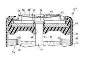
- Electrochemical cell 10includes a cylindrical steel can 12 having a closed bottom end 14 , an open top end 16 , and a cylindrical side wall extending between the bottom and top ends.
- the closed bottom end 14 of can 12has a positive cover welded or otherwise attached thereto and formed of plated steel, with a protruding nubbin 18 at its center region, which forms the positive contact terminal of cell 10 .
- Assembled to the open top end 16 of steel can 12is the collector and seal assembly 30 , and an outer negative cover 50 , preferably formed of plated steel, which forms the negative contact terminal of cell 10 .
- a metalized, plastic film label 20is formed about the exterior surface of steel can 12 , except for the ends of steel can 12 . Film label 20 is formed over the peripheral edge of the positive cover and may extend partially over the peripheral edge of the negative cover 50 .
- a positive electrode 22is formed about the interior surface of steel can 12 .
- the cathode 22is formed of a mixture of manganese dioxide, graphite, potassium hydroxide solution, and additives.
- a separator 24which is preferably formed of a non-woven fabric that prevents migration of any solid particles in the cell, is disposed about the interior surface of cathode 22 .
- a negative electrode 26also referred to herein as the anode 26 , is disposed with an electrolyte inside the separator 24 and in contact with a current collector 32 .
- the electrolytemay include an alkaline electrolyte containing potassium hydroxide (KOH).
- the anode 26is formed of zinc powder, a gelling agent, and additives.
- the manganese dioxide and zinc employed in the cathode 22 and anode 26 , respectively,are electrochemically active materials. Accordingly, the cathode 22 is configured as the cell's positive electrode, and the anode 26 is configured as the cell's negative electrode.
- the current collector 32contacts the outer negative cover 50 which forms the negative contact terminal of cell 10 .
- the current collector 32is generally configured in the shape of a nail having an elongated cylindrical shaft 34 , a truncated conical tip 35 at the lower end, and an enlarged head 36 at the upper end.
- the elongated shaft 34is disposed in contact with the anode 26 and, in this embodiment, has a substantially uniform diameter.
- the current collector 32is connected to the outer negative terminal 50 via a coiled conductive connector 38 that is compressible.
- the coiled connector 38may be welded to the bottom surface of outer negative cover 50 and/or to the upper surface of enlarged head 36 of current collector 32 , or alternately may be held in contact therewith via pressure contact.
- Current collector 32 and connector 38serve as an electrical current path to provide the negative polarity at the outer negative cover 50 .
- An annular polymeric seal 40is disposed in the open end of steel can 12 to prevent leakage of electrochemically active cell materials contained in steel can 12 .
- Polymeric seal 40may comprise a synthetic thermoplastic resin such as nylon.
- Alternate materials for seal 40may include polypropylene, such as Noryl® Extend which is commercially available from General Electric Company, and other materials that would be recognized as suitable for seal 40 .
- Seal 40has a central hub 42 with an inner upstanding cylindrical wall 44 defining a central opening (i.e., aperture) for receiving the current collector 32 .
- Hub 42is generally defined as the central portion of seal 40 containing upstanding wall 44 which is compressed against the current collector 32 .
- the enlarged head 36 of current collector 32is generally oversized for the hub opening, and thus the seal 40 is compressed against the current collector 32 to form an interference fit engagement with the inner upstanding wall 44 defining the hub opening.
- the upstanding wall 44 of central hub 42is configured to sealingly engage the enlarged head 36 of current collector 32 when in a sealed (non-vented) position.
- the central hub 42also has an upper edge 43 shown in FIG. 1 formed over the upper peripheral surface of enlarged head 36 to further resist upward movement of current collector 32 .
- An inner cover 46which is preferably formed of a rigid metal, is provided to increase the rigidity and support the radial compression of annular seal 40 , thereby improving the sealing effectiveness.
- the inner cover 46is configured to contact an outer upstanding wall of central hub 42 and an upstanding wall at the outer peripheral section 45 of seal 40 . While an oversized current collector 32 and an inner cover 46 are used to compress the seal 40 against the current collector 32 , other compression techniques such as compression rings may be employed to provide a sealed interference fit engagement between the current collector 32 and seal 40 .
- the seal 40 , inner cover 46 , and outer negative cover 50provide a low profile closure to the open end 16 of can 12 .
- the outer negative cover 50also includes one or more vent openings 52 that serve to expose the non-sealed volume of cell 10 to the surrounding outside atmosphere. Vent openings 52 serve to vent pressure build-up released from within the cell 10 to the outside atmosphere once the collector and seal assembly 30 vents.
- the current collector 32 , annular seal 40 , and inner cover 46form the collector and seal assembly 30 which may be assembled together and inserted as a unit into the open end 16 of steel can 12 .
- the assembly of the collector and seal assembly 30 and closure of the open end 16 of can 12include disposing the annular polymeric seal 40 in the open end 16 of the can 12 , which may have a flared opening or a bead formed radially inward on the inner wall of the can 12 , and crimping the upper end of the can 12 inwardly and over the outer periphery 45 of the seal 40 to compress the seal 40 against the inner cover 46 .
- the outer negative cover 50is electrically insulated from the steel can 12 by way of annular polymeric seal 40 .
- the current collector and seal assembly 30seals closed the open end 16 of can 12 , provides an electrical current path to the outer negative terminal 50 , and further acts a pressure relief mechanism when exposed to an excessive pressure differential.
- the collector and seal assembly 30is designed to release pressurized gases from within the sealed active volume of cell 10 when the assembly 30 is exposed to a predetermined pressure differential.
- the pressure differentialis the difference between the internal pressure below the seal 40 and the atmospheric pressure above the seal 40 .
- the pressurized gas ventingis generally achieved by relative axial (i.e., parallel to a longitudinal axis of the current collector 32 ) movement between the current collector 32 and annular polymeric seal 40 .
- the pressurized gases released from the internal volumeexit cell 10 via openings 52 provided in the outer negative cover 50 .
- current collector 32is interference fit and sealingly engaged with annular seal 40 while in the sealed (non-vented) position as shown in FIG. 1 .
- the sealing engagementis formed between the head 36 of collector 32 and the upstanding wall forming hub 42 of seal 40 .
- the internal pressureapplies a force on the current collector 32 which will tend to urge the current collector 32 upward and out of sealing engagement with annular seal 40 .
- the pressure differential of the internal sealed volumeas compared to the outer atmospheric pressure, exceeds a predetermined pressure threshold, the current collector 32 is forced free from the sealing engagement with the hub 42 of seal 40 and moves to a vented position as shown in FIG.
- coiled conductive connector 38When compressed, coiled conductive connector 38 may apply an opposing spring bias force downward such that when the pressure differential decreases to a reduced pressure threshold, the current collector 32 may be biased downward so that the collector head 36 sealingly engages the seal hub 42 . In the event that the internal pressure increases after resealing, the current collector 32 will again be forced upward to open the pressure relief passage 48 to further vent pressurized gases.
- FIGS. 3 and 4An electrochemical cell 10 ′ is shown in FIGS. 3 and 4 having an alternatively configured current collector 32 ′ as part of a collector and seal assembly 30 ′.
- the current collector 32 ′includes a main shaft 34 that extends to the uppermost end, without the enlarged head portion as discussed above. Instead, current collector 32 ′ includes a plurality of longitudinal flutes (i.e., channels) 62 extending upward toward the uppermost end. It is preferred that the inner upstanding wall forming the hub of seal 40 be no higher than the length of the flutes 62 .
- the current collector 32 ′is positioned in the sealed position such that the plurality of flutes 62 are located below seal 40 , as shown in FIG. 3 .
- the current collector 32 ′is interference fit and sealingly engaged with the inner upstanding wall forming the opening in hub 42 of seal 40 .
- the current collector 32 ′is forced upward relative to the entire hub 42 of seal 40 which remains substantially fixed in place as discussed above.
- the longitudinal flutes 62provide a pressure relief passage around the inner upstanding wall forming the hub of seal 40 as shown in FIG. 4 . While a plurality of flutes 62 is shown, it should be appreciated that any one or more flutes may be employed according to this embodiment.
- an electrochemical cell 10 ′′is shown similar to cell 10 of FIG. 1 , except having an alternatively configured conductive connector 38 ′ for providing an electrical current path between the current collector 32 and outer negative cover 50 .
- Conductive connector 38 ′is shown in FIG. 7 generally configured as a bowl-shaped disk made of conductive material, such as steel. With particular reference to FIG. 5 , the upper outer peripheral rim engages the bottom surface of outer negative cover 50 , while the bottom dome contacts the upper surface of current collector head 36 .
- Conductive connector 38 ′preferably provides a downward biased force to the current collector 32 so as to maintain a sealed engagement with the annular seal 40 while in the sealed (non-vented) position.
- the current collector 32moves to a vented position, as shown in FIG. 6 , during which the conductive connector 38 ′ compresses vertically to allow formation of the pressure relief passage 48 .
- the conductive connector 38 ′may force the current collector 32 back into sealing engagement with seal 40 , as discussed above in connection with the first embodiment.
- Electrochemical cell 110is shown in FIGS. 8-10 having a collector and seal assembly 130 according to a fourth embodiment of the present invention.
- Electrochemical cell 110includes a steel can 12 , label 20 , cathode 22 , separator 24 , and an anode 26 , as described above in connection with the first and second embodiments.
- electrochemical cell 110includes collector and seal assembly 130 for sealing closed the open end 16 of can 12 , providing an electrical current path to an outer negative cover 150 , and providing a pressure relief mechanism to vent pressurized gases.
- the collector and seal assembly 130includes an annular polymeric seal 140 and a current collector 132 .
- the current collector and seal assembly 130 of the fourth embodimentdoes not require an inner cover as used in the collector and seal assemblies of the first, second, and third embodiments described above.
- the current collector 132includes a lower cylindrical shaft 134 , an enlarged diameter step 139 , a reduced diameter cylindrical shaft 137 , and an enlarged head 136 at the upper end.
- the lower shaft 134 of current collector 132extends into and contacts anode 26 .
- the reduced diameter shaft 137is located between the enlarged diameter step 139 and enlarged head 136 , and preferably has a diameter less than the diameter of the lower shaft 134 .
- the upper surface of enlarged head 136may be welded to, or in pressure contact with, outer negative cover 150 .
- the annular seal 140includes a central hub 142 having an inner upstanding wall 144 defining a central opening for receiving the current collector 132 .
- the outer peripheral portion 145 of seal 140forms a sealed closure against the can 12 and provides dielectric isolation between steel can 12 and outer negative cover 150 . It should be appreciated that the open end 16 of the can 12 , seal 140 , and outer cover 150 are crimped so as to compress the seal 140 and provide a sealed closure.
- the current collector 132is interference fit within the opening formed by inner upstanding wall 144 of seal 140 .
- the inner upstanding wall 144 of seal 140is compressed against current collector 132 and sealingly engages the current collector 132 when in a sealed (non-vented) position as shown in FIG. 8 .
- the electrochemical cell 110is shown with the collector and seal assembly 130 in a vented position.
- the central hub 142 of seal 140is forced upward due to the differential pressure applied to the seal 140 .
- hub 142is forced over the enlarged diameter step 139 to a position above step 139 to provide a pressure relief passage 148 between seal 140 and current collector 132 .
- the entire hub 142is forced upward relative to the current collector 132 which remains substantially fixed in place.
- Outer cover 150includes one or more vent openings 152 to vent pressure build-up released from within cell 110 to the outside atmosphere.
- the hub 142 of seal 140may slide downwardly (retract) back into sealing engagement on the upper side of the enlarged diameter step 139 as shown in FIG. 10 .
- Central hub 142 of seal 140has a shaped surface indentation (bevel) 141 provided in the lower section of upstanding wall 144 which substantially conforms to the shape of the upper surface of enlarged diameter step 139 .
- the seal 140may again sealingly engage current collector 132 to prevent further discharge of gases and other material. It should be appreciated that upon the pressure differential increasing, additional venting of pressurized gases may occur.
- the annular polymeric seal 140is shown having a plurality of channels 160 formed in the upper surface. It should be appreciated that by employing one or more standoff members, such as channels 160 , in the upper surface of seal 140 , the channels 160 provide a vent path to prevent resealing of seal 140 with current collector 132 when in the vent position. It should also be appreciated that as an alternative to channels, other standoff members, such as ribs or other surface protrusions, may be provided either on the upper surface of seal 140 or on the surface of current collector 130 to prevent resealing during the venting operation. Examples of anti-resealing assemblies are disclosed in U.S. Application Ser. No. 09/300,413, filed Apr.
- an electrochemical cell 110 ′is illustrated having a collector and seal assembly 130 ′ according to a fifth embodiment of the present invention.
- the electrochemical cell 110likewise includes a steel can 12 , label 20 , cathode 22 , separator 24 , anode 26 , and other components as discussed above.
- the collector and seal assembly 130 ′ of the fifth embodimentincludes a current collector 132 ′ having a lower shaft 134 , an enlarged diameter step 139 , and a plurality of longitudinal flutes (i.e., channels) 162 extending from the enlarged diameter step 139 upward toward the enlarged head 136 .
- the current collector 132 ′is likewise connected to the outer negative cover 150 .
- the plurality of flutes 162provide pressure relief passages 148 for releasing pressurized gases from the internal volume of the cell 110 ′ in a controlled operation.
- the hub 142 of seal 140provides sealing engagement between upstanding walls 144 and each of shaft 134 and step 139 of current collector 132 ′.
- the shaft 134 of current collector 132 ′is interference fit within the opening formed by the inner walls of hub 142 of seal 140 .
- the central hub 142slides upward along current collector 132 ′ until one or more pressure relief passages 148 are provided through flutes 162 to release the high pressure gases from within the sealed volume, as shown in FIG. 13 .
- the current collector 132 ′remains substantially fixed, relative to the movement of the entire hub 142 of seal 140 , as discussed above.
- a controlled low pressure release of gasesmay be achieved according to this embodiment.
- the seal member 140is made of a polymeric material, such as Noryl® Extend which is commercially available from General Electric Company of Selkirk, N.Y.
- Noryl® Extendis a polypropylene matrix having polyethylene therein, which acts as a polymer stiffener.
- Noryl® Extendprovides low moisture absorption, will not hydrolyze in the presence of KOH, and has very low stress relaxation. These characteristics allow the seal design of the present invention to be feasible, whereas use of a material such as nylon for the seal 140 of the present invention would require the use of a support. This is due to nylon cracking in the presence of KOH coupled with stress on the seal (in the hoop direction) due to the nail vent design.
- seal 140is a preferred material for seal 140 that resists cracking, particularly in the central hub
- other seal materialscould be used.
- the seal members 40 and 140may include nylon, such as Zytel® 101F, which is commercially available from E. I. duPont deNemours and Co. Inc. Seal members 40 and 140 can be integrally formed using a conventional injection molding process.
- the bottom surface of seal members 40 and 140may be coated with a layer of asphalt (not shown) or other suitable material to prevent chemical degradation of the seal member due to the presence of electrolyte.
- vent passagesmay be provided.
- the relative movement between the seal and collectormay be designed to cause the seal hub to split open, thereby further creating a pressure relief passage through the split opening.
- the present inventionadvantageously provides collector and seal assemblies for sealing the open end of an electrochemical cell and realizing a controlled venting operation to vent high pressure gases, particularly when the cell is subjected to an abusive condition.
- the collector and seal assemblies of the present inventioneach offer a simplified seal design in a low profile assembly which results in greater volume available for active battery components.
- the seals of the present inventionare easy to mold, since no conventional thin sections are required for the vent diaphragm.
- a wide range of vent pressuresis achievable by adjusting the nail step diameter in its relation to the seal hub inside diameter, seal hub outside diameter, and nail diameter below the enlarged diameter step. The venting rate can easily be adjusted with the collector and seal assemblies of the present application.
- the pressurized gases in the cellwill escape faster if the diameter difference between the vent region of the nail and seal is made greater, and if the vent channel cross section area on top of the seal is increased.
- the sealcan be designed to vent slower to create less release spray if the diameter clearance is decreased or the vent channel is decreased.
- collector and seal assemblieshave been described herein in connection with a cylindrical bobbin-type electrochemical cell, it should be appreciated that the invention concepts are likewise applicable to various other cell configurations including jelly roll cells, prismatic cells, cells employing multiple anodes and multiple current collectors and cells in which the cans and current collectors are electrically connected to the negative and positive electrodes, respectively. Additionally, it should also be appreciated that the collector and seal assemblies described herein may be sealed closed against the steel can using various different can closures.
Landscapes
- Chemical & Material Sciences (AREA)
- Chemical Kinetics & Catalysis (AREA)
- Electrochemistry (AREA)
- General Chemical & Material Sciences (AREA)
- Gas Exhaust Devices For Batteries (AREA)
- Sealing Battery Cases Or Jackets (AREA)
- Primary Cells (AREA)
- Connection Of Batteries Or Terminals (AREA)
- Cell Electrode Carriers And Collectors (AREA)
Abstract
Description
Claims (23)
Priority Applications (8)
| Application Number | Priority Date | Filing Date | Title |
|---|---|---|---|
| US10/034,687US6855454B2 (en) | 2001-12-20 | 2001-12-20 | Electrochemical cell having venting current collector and seal assembly |
| AU2002361648AAU2002361648A1 (en) | 2001-12-20 | 2002-12-12 | Electrochemical cell having venting current collector and seal assembly |
| JP2003555601AJP4421896B2 (en) | 2001-12-20 | 2002-12-12 | Electrochemical cell with vent current collector and seal assembly |
| CNB028258525ACN100336243C (en) | 2001-12-20 | 2002-12-12 | Electrochemical cell with ventable current collector and seal assembly |
| PCT/US2002/039744WO2003054983A2 (en) | 2001-12-20 | 2002-12-12 | Electrochemical cell having venting current collector and seal assembly |
| EP02797287AEP1456894B1 (en) | 2001-12-20 | 2002-12-17 | Electrochemical cell having venting current collector and seal assembly |
| HK05101955.6AHK1069483B (en) | 2001-12-20 | 2002-12-17 | Electrochemical cell having venting current collector and seal assembly |
| US10/970,323US7122270B2 (en) | 2001-12-20 | 2004-10-21 | Electrochemical cell having venting current collector and seal assembly |
Applications Claiming Priority (1)
| Application Number | Priority Date | Filing Date | Title |
|---|---|---|---|
| US10/034,687US6855454B2 (en) | 2001-12-20 | 2001-12-20 | Electrochemical cell having venting current collector and seal assembly |
Related Child Applications (1)
| Application Number | Title | Priority Date | Filing Date |
|---|---|---|---|
| US10/970,323ContinuationUS7122270B2 (en) | 2001-12-20 | 2004-10-21 | Electrochemical cell having venting current collector and seal assembly |
Publications (2)
| Publication Number | Publication Date |
|---|---|
| US20030118892A1 US20030118892A1 (en) | 2003-06-26 |
| US6855454B2true US6855454B2 (en) | 2005-02-15 |
Family
ID=21877969
Family Applications (2)
| Application Number | Title | Priority Date | Filing Date |
|---|---|---|---|
| US10/034,687Expired - LifetimeUS6855454B2 (en) | 2001-12-20 | 2001-12-20 | Electrochemical cell having venting current collector and seal assembly |
| US10/970,323Expired - LifetimeUS7122270B2 (en) | 2001-12-20 | 2004-10-21 | Electrochemical cell having venting current collector and seal assembly |
Family Applications After (1)
| Application Number | Title | Priority Date | Filing Date |
|---|---|---|---|
| US10/970,323Expired - LifetimeUS7122270B2 (en) | 2001-12-20 | 2004-10-21 | Electrochemical cell having venting current collector and seal assembly |
Country Status (6)
| Country | Link |
|---|---|
| US (2) | US6855454B2 (en) |
| EP (1) | EP1456894B1 (en) |
| JP (1) | JP4421896B2 (en) |
| CN (1) | CN100336243C (en) |
| AU (1) | AU2002361648A1 (en) |
| WO (1) | WO2003054983A2 (en) |
Cited By (3)
| Publication number | Priority date | Publication date | Assignee | Title |
|---|---|---|---|---|
| US20050053832A1 (en)* | 2001-12-20 | 2005-03-10 | Ray Robert E. | Electrochemical cell having venting current collector and seal assembly |
| US20060228623A1 (en)* | 2003-06-26 | 2006-10-12 | Ryuichiro Ebi | Battery pack and method of producing the same |
| US20080026286A1 (en)* | 2006-07-31 | 2008-01-31 | Eveready Battery Company, Inc. | Nail-type current collector with non-conductive core and surface metallization for electrochemical cell |
Families Citing this family (29)
| Publication number | Priority date | Publication date | Assignee | Title |
|---|---|---|---|---|
| USD490773S1 (en) | 2003-06-11 | 2004-06-01 | Matsushita Electric Industrial Co., Ltd. | Current collector for a battery |
| US20050048366A1 (en)* | 2003-08-27 | 2005-03-03 | Bowden William L. | Cathode material and method of manufacturing |
| TW200529484A (en)* | 2003-11-13 | 2005-09-01 | Rovcal Inc | Pressure dissipation assembly for electrochemical cell |
| KR100560494B1 (en)* | 2003-11-29 | 2006-03-13 | 삼성에스디아이 주식회사 | Cap Assembly and Secondary Battery Using the Same |
| USD522452S1 (en) | 2004-09-13 | 2006-06-06 | Matsushita Electric Industrial Co., Ltd. | Insulating plate for a battery |
| FR2894381B1 (en)* | 2005-12-05 | 2008-02-15 | Batscap Sa | ELECTRIC ENERGY STORAGE SYSTEM |
| KR101387636B1 (en)* | 2007-05-08 | 2014-04-23 | 비에스 앤 비 세프티 시스템즈 리미티드 | Pressure response membrane |
| US8399124B2 (en)* | 2007-06-29 | 2013-03-19 | Eveready Battery Company, Inc. | Vapor transmission resistant seal members for nonaqueous electrochemical cells |
| JP2011216217A (en)* | 2010-03-31 | 2011-10-27 | Panasonic Corp | Alkaline dry battery |
| JP5514632B2 (en)* | 2010-05-27 | 2014-06-04 | Fdkエナジー株式会社 | Cylindrical battery sealing gasket and cylindrical battery |
| GB201118842D0 (en)* | 2011-11-01 | 2011-12-14 | Euro Celtique Sa | Dispenser cap arrangement |
| CN102522518B (en)* | 2011-12-02 | 2013-09-25 | 苏州冠硕新能源有限公司 | Battery connecting assembly, producing method thereof and lithium battery |
| DE102012222836A1 (en)* | 2012-12-12 | 2014-06-12 | Robert Bosch Gmbh | Housing for a gas-tight accumulator |
| DE102015111572A1 (en)* | 2015-07-16 | 2017-01-19 | Schuler Pressen Gmbh | Battery cell housing and method for its manufacture |
| WO2017100841A1 (en)* | 2015-12-14 | 2017-06-22 | Aquahydrex Pty Ltd | Electrochemical cell that operates efficiently with fluctuating currents |
| DE102016004648A1 (en)* | 2016-04-16 | 2017-10-19 | Daimler Ag | Pressure relief device for a battery case, battery case with the pressure relief device, battery and method for depressurizing a battery |
| CN109937494B (en)* | 2017-01-06 | 2021-09-17 | 宁德时代新能源科技股份有限公司 | Power battery top cover structure, power battery and battery module |
| KR102684440B1 (en) | 2017-03-30 | 2024-07-12 | 도날드슨 컴파니, 인코포레이티드 | Vent with relief valve |
| US11469463B2 (en)* | 2018-02-20 | 2022-10-11 | Panasonic Intellectual Property Management Co., Ltd. | Cylindrical battery |
| JP7049865B2 (en)* | 2018-03-06 | 2022-04-07 | Fdk株式会社 | Alkaline batteries and methods for manufacturing alkaline batteries |
| DE102018210841A1 (en) | 2018-07-02 | 2020-01-02 | Volkswagen Aktiengesellschaft | Bushing element and system from a separation layer and a bushing element |
| DE102019100094A1 (en)* | 2019-01-04 | 2020-07-09 | Mann+Hummel Gmbh | Degassing unit and electronics housing, in particular battery housing |
| CN110165120B (en)* | 2019-05-15 | 2022-04-08 | 广东微电新能源有限公司 | Battery structure with deformation pressure relief function |
| US11101597B1 (en) | 2020-05-06 | 2021-08-24 | Lear Corporation | Vented electrical connector |
| US11817591B2 (en) | 2020-05-22 | 2023-11-14 | Duracell U.S. Operations, Inc. | Seal assembly for a battery cell |
| CN113675510B (en)* | 2021-08-17 | 2023-01-24 | 厦门海辰储能科技股份有限公司 | The end connection structure of the battery cell, the battery cell, and the power battery |
| WO2023052878A2 (en)* | 2021-09-29 | 2023-04-06 | Medtronic, Inc. | Current collector with vent channels |
| WO2025182677A1 (en)* | 2024-02-29 | 2025-09-04 | パナソニックIpマネジメント株式会社 | Sealed battery |
| US20250293384A1 (en)* | 2024-03-13 | 2025-09-18 | GM Global Technology Operations LLC | Cell integrated vent gas diverter with particle trap |
Citations (33)
| Publication number | Priority date | Publication date | Assignee | Title |
|---|---|---|---|---|
| US454598A (en) | 1891-06-23 | Philip hathaway | ||
| US1650319A (en) | 1924-05-07 | 1927-11-22 | Nat Carbon Co Inc | Seal for galvanic cells |
| US2060799A (en) | 1932-11-30 | 1936-11-17 | Nat Carbon Co Inc | Closure for dry cells |
| US3062910A (en) | 1961-03-09 | 1962-11-06 | Gould National Batteries Inc | Sealing and pressure relief device for galvanic cells |
| US3497104A (en) | 1966-10-10 | 1970-02-24 | Alkaline Batteries Ltd | Venting devices for electric storage cells |
| CA959926A (en) | 1970-04-09 | 1974-12-24 | Mallory (P.R.) And Co. Inc. | Leakproof primary cell |
| CA962736A (en) | 1970-08-07 | 1975-02-11 | Sumio Uchida | Cell jacket for metal/air or metal/oxygen cells |
| US3923548A (en) | 1972-05-24 | 1975-12-02 | Varta Batterie | Elastic gas valve for galvanic cells |
| US3967977A (en) | 1975-03-28 | 1976-07-06 | Union Carbide Corporation | Closure for galvanic dry cells |
| US3980500A (en) | 1975-05-30 | 1976-09-14 | Gould Inc. | Resealable vent for plastic battery case |
| US4366213A (en) | 1981-06-16 | 1982-12-28 | Tamminen Pentti J | Battery and contact combination |
| US4431716A (en) | 1983-02-11 | 1984-02-14 | Honeywell Inc. | Heat activated vent |
| JPS5933751A (en) | 1982-08-17 | 1984-02-23 | Hitachi Maxell Ltd | cylindrical alkaline battery |
| US4567118A (en) | 1983-07-11 | 1986-01-28 | Duracell Inc. | Cell vent |
| US4672010A (en) | 1986-07-18 | 1987-06-09 | Eveready Battery Company | Terminal pin-collector plate assembly for hermetically sealed cells |
| GB2215119A (en) | 1988-02-04 | 1989-09-13 | Ever Ready Ltd | Cell |
| EP0349156A1 (en) | 1988-06-25 | 1990-01-03 | Tucker Fasteners Limited | Electrical storage cell |
| US5080985A (en) | 1989-12-07 | 1992-01-14 | Duracell Inc. | High pressure seal for alkaline cells |
| JPH05144445A (en) | 1991-11-22 | 1993-06-11 | Fuji Elelctrochem Co Ltd | Method for manufacturing cylindrical alkaline battery |
| US5227261A (en) | 1991-10-15 | 1993-07-13 | Eveready Battery Company, Inc. | Cylindrical electrochemical cells with a diaphragm seal |
| JPH05182648A (en) | 1991-12-28 | 1993-07-23 | Sony Corp | Alkaline battery |
| JPH05325929A (en) | 1992-05-20 | 1993-12-10 | Hitachi Maxell Ltd | Alkaline storage battery |
| US5532075A (en) | 1994-07-06 | 1996-07-02 | Alexander Manufacturing Corporation | Small battery cell |
| JPH08250083A (en) | 1995-03-07 | 1996-09-27 | Keihin Rika Kogyo:Kk | Non-aqueous battery |
| JPH09153351A (en) | 1995-11-30 | 1997-06-10 | Sanyo Electric Co Ltd | Sealed battery |
| US5667912A (en) | 1993-08-04 | 1997-09-16 | Eveready Battery Company, Inc. | Current collector assembly for an electrochemical cell |
| JPH09245758A (en) | 1996-03-08 | 1997-09-19 | Sony Corp | Um-3 (aa)-type alkaline battery |
| WO1999065091A1 (en) | 1998-06-12 | 1999-12-16 | Matsushita Electric Industrial Co., Ltd. | Sealing structure for an alkali battery |
| JP2000011981A (en) | 1998-06-25 | 2000-01-14 | Shin Kobe Electric Mach Co Ltd | Non-aqueous electrolyte secondary battery |
| US6022635A (en) | 1997-09-24 | 2000-02-08 | Eveready Battery Company, Inc. | Electrochemical cell having a moisture barrier |
| WO2000011740A1 (en) | 1998-08-21 | 2000-03-02 | Eveready Battery Company, Inc. | Battery constructions having reduced collector assembly volume |
| JP2000138041A (en) | 1998-10-30 | 2000-05-16 | Sanyo Electric Co Ltd | Nonaqueous electrolyte battery |
| WO2001020693A1 (en) | 1999-09-14 | 2001-03-22 | Eveready Battery Company, Inc. | Current collector and seal assembly for electrochemical cell |
Family Cites Families (6)
| Publication number | Priority date | Publication date | Assignee | Title |
|---|---|---|---|---|
| JPS541008A (en) | 1977-06-03 | 1979-01-06 | Efu Tei Giken Kk | Vtr system |
| US4227701A (en)* | 1979-01-02 | 1980-10-14 | Fuji Electrochemical Co., Ltd. | Rupturable sealing structure of cell |
| US5188909A (en)* | 1991-09-12 | 1993-02-23 | Eveready Battery Co., Inc. | Electrochemical cell with circuit disconnect device |
| US6127062A (en)* | 1998-03-24 | 2000-10-03 | Duracell Inc | End cap seal assembly for an electrochemical cell |
| JP3432746B2 (en) | 1998-06-18 | 2003-08-04 | 株式会社三ツ星電器製作所 | Ceiling-mounted lighting fixture mounting device |
| US6855454B2 (en)* | 2001-12-20 | 2005-02-15 | Eveready Battery Company, Inc. | Electrochemical cell having venting current collector and seal assembly |
- 2001
- 2001-12-20USUS10/034,687patent/US6855454B2/ennot_activeExpired - Lifetime
- 2002
- 2002-12-12JPJP2003555601Apatent/JP4421896B2/ennot_activeExpired - Fee Related
- 2002-12-12AUAU2002361648Apatent/AU2002361648A1/ennot_activeAbandoned
- 2002-12-12CNCNB028258525Apatent/CN100336243C/ennot_activeExpired - Fee Related
- 2002-12-12WOPCT/US2002/039744patent/WO2003054983A2/enactiveApplication Filing
- 2002-12-17EPEP02797287Apatent/EP1456894B1/ennot_activeExpired - Lifetime
- 2004
- 2004-10-21USUS10/970,323patent/US7122270B2/ennot_activeExpired - Lifetime
Patent Citations (34)
| Publication number | Priority date | Publication date | Assignee | Title |
|---|---|---|---|---|
| US454598A (en) | 1891-06-23 | Philip hathaway | ||
| US1650319A (en) | 1924-05-07 | 1927-11-22 | Nat Carbon Co Inc | Seal for galvanic cells |
| US2060799A (en) | 1932-11-30 | 1936-11-17 | Nat Carbon Co Inc | Closure for dry cells |
| US3062910A (en) | 1961-03-09 | 1962-11-06 | Gould National Batteries Inc | Sealing and pressure relief device for galvanic cells |
| US3497104A (en) | 1966-10-10 | 1970-02-24 | Alkaline Batteries Ltd | Venting devices for electric storage cells |
| CA959926A (en) | 1970-04-09 | 1974-12-24 | Mallory (P.R.) And Co. Inc. | Leakproof primary cell |
| CA962736A (en) | 1970-08-07 | 1975-02-11 | Sumio Uchida | Cell jacket for metal/air or metal/oxygen cells |
| US3923548A (en) | 1972-05-24 | 1975-12-02 | Varta Batterie | Elastic gas valve for galvanic cells |
| US3967977A (en) | 1975-03-28 | 1976-07-06 | Union Carbide Corporation | Closure for galvanic dry cells |
| US3980500A (en) | 1975-05-30 | 1976-09-14 | Gould Inc. | Resealable vent for plastic battery case |
| US4366213A (en) | 1981-06-16 | 1982-12-28 | Tamminen Pentti J | Battery and contact combination |
| JPS5933751A (en) | 1982-08-17 | 1984-02-23 | Hitachi Maxell Ltd | cylindrical alkaline battery |
| US4431716A (en) | 1983-02-11 | 1984-02-14 | Honeywell Inc. | Heat activated vent |
| US4567118A (en) | 1983-07-11 | 1986-01-28 | Duracell Inc. | Cell vent |
| US4672010A (en) | 1986-07-18 | 1987-06-09 | Eveready Battery Company | Terminal pin-collector plate assembly for hermetically sealed cells |
| GB2215119A (en) | 1988-02-04 | 1989-09-13 | Ever Ready Ltd | Cell |
| EP0349156A1 (en) | 1988-06-25 | 1990-01-03 | Tucker Fasteners Limited | Electrical storage cell |
| US5080985A (en) | 1989-12-07 | 1992-01-14 | Duracell Inc. | High pressure seal for alkaline cells |
| US5227261A (en) | 1991-10-15 | 1993-07-13 | Eveready Battery Company, Inc. | Cylindrical electrochemical cells with a diaphragm seal |
| JPH05144445A (en) | 1991-11-22 | 1993-06-11 | Fuji Elelctrochem Co Ltd | Method for manufacturing cylindrical alkaline battery |
| JPH05182648A (en) | 1991-12-28 | 1993-07-23 | Sony Corp | Alkaline battery |
| JPH05325929A (en) | 1992-05-20 | 1993-12-10 | Hitachi Maxell Ltd | Alkaline storage battery |
| US5667912A (en) | 1993-08-04 | 1997-09-16 | Eveready Battery Company, Inc. | Current collector assembly for an electrochemical cell |
| US5532075A (en) | 1994-07-06 | 1996-07-02 | Alexander Manufacturing Corporation | Small battery cell |
| US5588970A (en) | 1994-07-06 | 1996-12-31 | Hughett; Elmer | Method for vacuum filling and sealing of a battery cell |
| JPH08250083A (en) | 1995-03-07 | 1996-09-27 | Keihin Rika Kogyo:Kk | Non-aqueous battery |
| JPH09153351A (en) | 1995-11-30 | 1997-06-10 | Sanyo Electric Co Ltd | Sealed battery |
| JPH09245758A (en) | 1996-03-08 | 1997-09-19 | Sony Corp | Um-3 (aa)-type alkaline battery |
| US6022635A (en) | 1997-09-24 | 2000-02-08 | Eveready Battery Company, Inc. | Electrochemical cell having a moisture barrier |
| WO1999065091A1 (en) | 1998-06-12 | 1999-12-16 | Matsushita Electric Industrial Co., Ltd. | Sealing structure for an alkali battery |
| JP2000011981A (en) | 1998-06-25 | 2000-01-14 | Shin Kobe Electric Mach Co Ltd | Non-aqueous electrolyte secondary battery |
| WO2000011740A1 (en) | 1998-08-21 | 2000-03-02 | Eveready Battery Company, Inc. | Battery constructions having reduced collector assembly volume |
| JP2000138041A (en) | 1998-10-30 | 2000-05-16 | Sanyo Electric Co Ltd | Nonaqueous electrolyte battery |
| WO2001020693A1 (en) | 1999-09-14 | 2001-03-22 | Eveready Battery Company, Inc. | Current collector and seal assembly for electrochemical cell |
Cited By (6)
| Publication number | Priority date | Publication date | Assignee | Title |
|---|---|---|---|---|
| US20050053832A1 (en)* | 2001-12-20 | 2005-03-10 | Ray Robert E. | Electrochemical cell having venting current collector and seal assembly |
| US7122270B2 (en)* | 2001-12-20 | 2006-10-17 | Eveready Battery Company, Inc. | Electrochemical cell having venting current collector and seal assembly |
| US20060228623A1 (en)* | 2003-06-26 | 2006-10-12 | Ryuichiro Ebi | Battery pack and method of producing the same |
| US7635535B2 (en)* | 2003-06-26 | 2009-12-22 | Panasonic Corporation | Battery pack comprising a battery and a terminal unit |
| US20080026286A1 (en)* | 2006-07-31 | 2008-01-31 | Eveready Battery Company, Inc. | Nail-type current collector with non-conductive core and surface metallization for electrochemical cell |
| US20080070098A1 (en)* | 2006-07-31 | 2008-03-20 | Ray Robert E Jr | Electrochemical cell and current collector assembly therefor |
Also Published As
| Publication number | Publication date |
|---|---|
| AU2002361648A1 (en) | 2003-07-09 |
| US20030118892A1 (en) | 2003-06-26 |
| US7122270B2 (en) | 2006-10-17 |
| AU2002361648A8 (en) | 2003-07-09 |
| US20050053832A1 (en) | 2005-03-10 |
| EP1456894B1 (en) | 2012-08-08 |
| WO2003054983A8 (en) | 2004-07-08 |
| JP2005514730A (en) | 2005-05-19 |
| HK1069483A1 (en) | 2005-05-20 |
| JP4421896B2 (en) | 2010-02-24 |
| EP1456894A2 (en) | 2004-09-15 |
| WO2003054983A2 (en) | 2003-07-03 |
| CN1636285A (en) | 2005-07-06 |
| WO2003054983A3 (en) | 2003-11-13 |
| CN100336243C (en) | 2007-09-05 |
Similar Documents
| Publication | Publication Date | Title |
|---|---|---|
| US6855454B2 (en) | Electrochemical cell having venting current collector and seal assembly | |
| JP2005514730A6 (en) | Electrochemical cell with vent current collector and seal assembly | |
| US6620543B2 (en) | Electrochemical cell having can vent and cover terminal | |
| US7704632B2 (en) | Electrochemical cell having a vent assembly with a rupturable seal member | |
| US20070275293A1 (en) | Battery can having vent and asymmetric welded cover | |
| US6346342B1 (en) | Battery having pressure relief mechanism formed in container | |
| US6312850B1 (en) | Current collector and seal assembly for electrochemical cell | |
| US6270919B1 (en) | Electrochemical cell having low profile seal assembly with anti-resealing vent | |
| US6495284B2 (en) | End seal assembly for an alkaline cell | |
| US6206938B1 (en) | Snap-through gasket for galvanic cells | |
| WO2000046864A2 (en) | Low profile ventable seal for an electrochemical cell | |
| WO2001037355A1 (en) | Electrochemical cell having venting cover | |
| HK1069483B (en) | Electrochemical cell having venting current collector and seal assembly |
Legal Events
| Date | Code | Title | Description |
|---|---|---|---|
| AS | Assignment | Owner name:EVEREADY BATTERY COMPANY, INC., OHIO Free format text:ASSIGNMENT OF ASSIGNORS INTEREST;ASSIGNORS:RAY, ROBERT E., JR.;WU, JAMES XIXIAN;REEL/FRAME:012450/0221 Effective date:20010511 | |
| RF | Reissue application filed | Effective date:20041029 | |
| STCF | Information on status: patent grant | Free format text:PATENTED CASE | |
| FPAY | Fee payment | Year of fee payment:4 | |
| FPAY | Fee payment | Year of fee payment:8 | |
| AS | Assignment | Owner name:ENERGIZER BRANDS, LLC, MISSOURI Free format text:ASSIGNMENT OF ASSIGNORS INTEREST;ASSIGNOR:EVEREADY BATTERY COMPANY, INC.;REEL/FRAME:036019/0814 Effective date:20150601 | |
| AS | Assignment | Owner name:JPMORGAN CHASE BANK, N.A., AS AGENT, ILLINOIS Free format text:SECURITY AGREEMENT;ASSIGNOR:ENERGIZER BRANDS, LLC;REEL/FRAME:036106/0392 Effective date:20150630 | |
| FPAY | Fee payment | Year of fee payment:12 | |
| AS | Assignment | Owner name:ENERGIZER BRANDS, LLC, MISSOURI Free format text:CORRECTIVE ASSIGNMENT TO CORRECT THE APPLICATION NUMBER 29/499,135 PREVIOUSLY RECORDED AT REEL: 036019 FRAME: 814. ASSIGNOR(S) HEREBY CONFIRMS THE ASSIGNMENT;ASSIGNOR:EVEREADY BATTERY COMPANY;REEL/FRAME:040054/0660 Effective date:20160601 | |
| AS | Assignment | Owner name:ENERGIZER BRANDS, LLC, MISSOURI Free format text:TERMINATION AND RELEASE OF SECURITY INTEREST IN PATENT RIGHTS;ASSIGNOR:JPMORGAN CHASE BANK, N.A., AS ADMINISTRATIVE AGENT;REEL/FRAME:048888/0300 Effective date:20190102 Owner name:JPMORGAN CHASE BANK, N.A., AS ADMINISTRATIVE AGENT, ILLINOIS Free format text:PATENT SECURITY AGREEMENT;ASSIGNORS:ENERGIZER HOLDINGS, INC.;AMERICAN COVERS, LLC;ASSOCIATED PRODUCTS, LLC;AND OTHERS;REEL/FRAME:048029/0246 Effective date:20190102 Owner name:JPMORGAN CHASE BANK, N.A., AS ADMINISTRATIVE AGENT Free format text:PATENT SECURITY AGREEMENT;ASSIGNORS:ENERGIZER HOLDINGS, INC.;AMERICAN COVERS, LLC;ASSOCIATED PRODUCTS, LLC;AND OTHERS;REEL/FRAME:048029/0246 Effective date:20190102 | |
| AS | Assignment | Owner name:JPMORGAN CHASE BANK, N.A., AS ADMINISTRATIVE AGENT, ILLINOIS Free format text:PATENT SECURITY AGREEMENT;ASSIGNORS:ENERGIZER BRANDS, LLC;ENERGIZER AUTO, INC.;REEL/FRAME:054875/0651 Effective date:20201222 Owner name:JPMORGAN CHASE BANK, N.A., AS ADMINISTRATIVE AGENT, ILLINOIS Free format text:PATENT SECURITY AGREEMENT;ASSIGNORS:ENERGIZER BRANDS, LLC;ENERGIZER AUTO, INC.;REEL/FRAME:054875/0504 Effective date:20201222 |