US6855159B1 - Surgical guide line assembly and separator assembly for use during a surgical procedure - Google Patents
Surgical guide line assembly and separator assembly for use during a surgical procedureDownload PDFInfo
- Publication number
- US6855159B1 US6855159B1US09/936,202US93620202AUS6855159B1US 6855159 B1US6855159 B1US 6855159B1US 93620202 AUS93620202 AUS 93620202AUS 6855159 B1US6855159 B1US 6855159B1
- Authority
- US
- United States
- Prior art keywords
- guide line
- assembly
- surgical
- distal end
- component
- Prior art date
- Legal status (The legal status is an assumption and is not a legal conclusion. Google has not performed a legal analysis and makes no representation as to the accuracy of the status listed.)
- Expired - Fee Related
Links
- 238000001356surgical procedureMethods0.000titleclaimsabstractdescription32
- 239000000463materialSubstances0.000claimsdescription4
- -1polytetrafluoroethylenePolymers0.000claims1
- 229920001343polytetrafluoroethylenePolymers0.000claims1
- 239000004810polytetrafluoroethyleneSubstances0.000claims1
- 238000000034methodMethods0.000abstractdescription6
- 230000000712assemblyEffects0.000description16
- 238000000429assemblyMethods0.000description16
- 238000010276constructionMethods0.000description10
- 206010002329AneurysmDiseases0.000description4
- 230000008878couplingEffects0.000description4
- 238000010168coupling processMethods0.000description4
- 238000005859coupling reactionMethods0.000description4
- 239000007787solidSubstances0.000description4
- 239000000560biocompatible materialSubstances0.000description2
- 238000002788crimpingMethods0.000description2
- 238000012986modificationMethods0.000description2
- 230000004048modificationEffects0.000description2
- 229920000544Gore-TexPolymers0.000description1
- 208000002223abdominal aortic aneurysmDiseases0.000description1
- 238000011161developmentMethods0.000description1
- 230000018109developmental processEffects0.000description1
- 238000005553drillingMethods0.000description1
- 238000003780insertionMethods0.000description1
- 230000037431insertionEffects0.000description1
- 239000002184metalSubstances0.000description1
- 238000012978minimally invasive surgical procedureMethods0.000description1
- 238000000926separation methodMethods0.000description1
- 230000007704transitionEffects0.000description1
Images


Classifications
- A—HUMAN NECESSITIES
- A61—MEDICAL OR VETERINARY SCIENCE; HYGIENE
- A61F—FILTERS IMPLANTABLE INTO BLOOD VESSELS; PROSTHESES; DEVICES PROVIDING PATENCY TO, OR PREVENTING COLLAPSING OF, TUBULAR STRUCTURES OF THE BODY, e.g. STENTS; ORTHOPAEDIC, NURSING OR CONTRACEPTIVE DEVICES; FOMENTATION; TREATMENT OR PROTECTION OF EYES OR EARS; BANDAGES, DRESSINGS OR ABSORBENT PADS; FIRST-AID KITS
- A61F2/00—Filters implantable into blood vessels; Prostheses, i.e. artificial substitutes or replacements for parts of the body; Appliances for connecting them with the body; Devices providing patency to, or preventing collapsing of, tubular structures of the body, e.g. stents
- A61F2/95—Instruments specially adapted for placement or removal of stents or stent-grafts
- A—HUMAN NECESSITIES
- A61—MEDICAL OR VETERINARY SCIENCE; HYGIENE
- A61B—DIAGNOSIS; SURGERY; IDENTIFICATION
- A61B17/00—Surgical instruments, devices or methods
- A61B17/04—Surgical instruments, devices or methods for suturing wounds; Holders or packages for needles or suture materials
- A61B17/0469—Suturing instruments for use in minimally invasive surgery, e.g. endoscopic surgery
- A—HUMAN NECESSITIES
- A61—MEDICAL OR VETERINARY SCIENCE; HYGIENE
- A61B—DIAGNOSIS; SURGERY; IDENTIFICATION
- A61B17/00—Surgical instruments, devices or methods
- A61B17/04—Surgical instruments, devices or methods for suturing wounds; Holders or packages for needles or suture materials
- A61B17/0482—Needle or suture guides
- A—HUMAN NECESSITIES
- A61—MEDICAL OR VETERINARY SCIENCE; HYGIENE
- A61B—DIAGNOSIS; SURGERY; IDENTIFICATION
- A61B17/00—Surgical instruments, devices or methods
- A61B17/04—Surgical instruments, devices or methods for suturing wounds; Holders or packages for needles or suture materials
- A61B17/06—Needles ; Sutures; Needle-suture combinations; Holders or packages for needles or suture materials
- A61B17/06004—Means for attaching suture to needle
- A61B2017/06028—Means for attaching suture to needle by means of a cylindrical longitudinal blind bore machined at the suture-receiving end of the needle, e.g. opposite to needle tip
- A—HUMAN NECESSITIES
- A61—MEDICAL OR VETERINARY SCIENCE; HYGIENE
- A61B—DIAGNOSIS; SURGERY; IDENTIFICATION
- A61B17/00—Surgical instruments, devices or methods
- A61B17/04—Surgical instruments, devices or methods for suturing wounds; Holders or packages for needles or suture materials
- A61B17/06—Needles ; Sutures; Needle-suture combinations; Holders or packages for needles or suture materials
- A61B2017/06057—Double-armed sutures, i.e. sutures having a needle attached to each end
- A—HUMAN NECESSITIES
- A61—MEDICAL OR VETERINARY SCIENCE; HYGIENE
- A61F—FILTERS IMPLANTABLE INTO BLOOD VESSELS; PROSTHESES; DEVICES PROVIDING PATENCY TO, OR PREVENTING COLLAPSING OF, TUBULAR STRUCTURES OF THE BODY, e.g. STENTS; ORTHOPAEDIC, NURSING OR CONTRACEPTIVE DEVICES; FOMENTATION; TREATMENT OR PROTECTION OF EYES OR EARS; BANDAGES, DRESSINGS OR ABSORBENT PADS; FIRST-AID KITS
- A61F2/00—Filters implantable into blood vessels; Prostheses, i.e. artificial substitutes or replacements for parts of the body; Appliances for connecting them with the body; Devices providing patency to, or preventing collapsing of, tubular structures of the body, e.g. stents
- A61F2/02—Prostheses implantable into the body
- A61F2/04—Hollow or tubular parts of organs, e.g. bladders, tracheae, bronchi or bile ducts
- A61F2/06—Blood vessels
- A61F2/07—Stent-grafts
- A—HUMAN NECESSITIES
- A61—MEDICAL OR VETERINARY SCIENCE; HYGIENE
- A61F—FILTERS IMPLANTABLE INTO BLOOD VESSELS; PROSTHESES; DEVICES PROVIDING PATENCY TO, OR PREVENTING COLLAPSING OF, TUBULAR STRUCTURES OF THE BODY, e.g. STENTS; ORTHOPAEDIC, NURSING OR CONTRACEPTIVE DEVICES; FOMENTATION; TREATMENT OR PROTECTION OF EYES OR EARS; BANDAGES, DRESSINGS OR ABSORBENT PADS; FIRST-AID KITS
- A61F2/00—Filters implantable into blood vessels; Prostheses, i.e. artificial substitutes or replacements for parts of the body; Appliances for connecting them with the body; Devices providing patency to, or preventing collapsing of, tubular structures of the body, e.g. stents
- A61F2/95—Instruments specially adapted for placement or removal of stents or stent-grafts
- A61F2002/9505—Instruments specially adapted for placement or removal of stents or stent-grafts having retaining means other than an outer sleeve, e.g. male-female connector between stent and instrument
- A61F2002/9511—Instruments specially adapted for placement or removal of stents or stent-grafts having retaining means other than an outer sleeve, e.g. male-female connector between stent and instrument the retaining means being filaments or wires
Definitions
- the present inventionrelates generally to a surgical guide line assembly.
- the present inventionis directed to a surgical guide line assembly for use in remote controlled surgical procedures.
- the present inventionalso related to a separator assembly for use in connection with the surgical guide line assembly to ensure that surgical components do not become entwined during a surgical procedure.
- the present inventionis directed to a surgical guide line assembly for use during a surgical procedure.
- the surgical guide line assemblypermits the manipulation of a surgical component within a vessel during a surgical procedure, such as for example an intravascular procedure.
- the surgical guide line assemblyincludes a guide line component having a proximal end and a distal end, and at least one suture secured to the distal end of the guide line component.
- the surgical guide line assemblymay further include a surgical needle connected to each of the at least one suture.
- the surgical guide line according to the present inventionmay further include a broad line assembly that is positioned around the distal end of the guide line component and a portion of the at least one suture. The broad line assembly produces a flexible curved end portion of the guide line assembly.
- the surgical guide line assemblymay further include a control assembly connected to the guide line component The control assembly permits manipulation of the guide line assembly within the vessel from a remote location.
- the present inventionis also directed to a surgical guide line assembly for use during a surgical procedure.
- the surgical guide assemblypermits the manipulation of a surgical component within a vessel during a surgical procedure, such as for example an intravascular procedure.
- the surgical guide line assemblyincludes a guide line component having a proximal end and a distal end, and at least one suture secured to the distal end of the guide line component.
- the surgical guide line assemblymay further include a surgical needle connected to each of the at least one suture.
- the at least one suture according to the present inventionmay be secured to the guide line component in one of several ways. It may be bonded directly to the component
- the at least one suturemay be secured to the guide line component within a formed cavity in the distal end of the guide line component. Alternatively, the suture may be secured to the distal end of the guide line component within a central passageway in the component.
- the guide line componentmay have a bent portion located adjacent the distal end.
- the guide line componentmay have an articulated portion located adjacent the distal end.
- the control assemblyis capable of permitting manipulation of the articulated portion of the guide line component.
- the present inventionis also directed to a surgical separator assembly for use in separating at least two surgical components during a surgical procedure in a vessel.
- the surgical separator assemblyincludes a separating assembly for receiving the at least two surgical components during the surgical procedure.
- the surgical separator assemblyfurther includes an advancing assembly for advancing the separating assembly within the vessel during the surgical procedure.
- the advancing assemblymay include a catheter.
- the separating assemblymay be rotatably connected to the advancing assembly.
- the separator assemblyfurther includes a control assembly for selectively locking the separating assembly to prevent rotation of the separating assembly.
- the separating assemblymay include at least two apertures therein. Each of the apertures is sized to receive at least a portion of a surgical component therein.
- the present inventionis also directed to a surgical system for use during a surgical procedure within a vessel.
- the surgical systemincludes both the guide line assemblies described herein in combination with the surgical separator assembly.
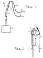
- FIG. 1is a perspective view of a guide line assembly according to an embodiment of the present invention
- FIG. 2is a schematic view of the guide line assembly according to FIG. 1 secured to a repair graft;
- FIG. 3is a schematic view of a guide line assembly according to another embodiment of the present invention secured to a repair graft;
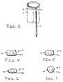
- FIG. 4is a cross section of the guide line component of FIGS. 1-3 according to one embodiment of the present invention.
- FIG. 5is a cross section of the guide line component of FIGS. 1-3 according to another embodiment of the present invention.
- FIG. 6is a cross section of the guide line component of FIGS. 1-3 according to another embodiment of the present invention.
- FIG. 7is a cross section of the guide line component of FIGS. 1-3 according to another embodiment of the present invention.
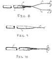
- FIG. 8is a partial cross section of a guide line assembly according to another embodiment of the present invention.
- FIG. 9is a perspective view of the guide line assembly according to the embodiment of FIG. 8 ;
- FIG. 10is a perspective view of a guide line assembly according to another embodiment of the present invention.
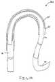
- FIG. 11is a perspective view of the end portion of the guide line component according to an embodiment of the present invention.
- FIG. 12is a perspective view of the end portion of the guide line component according to another embodiment of the present invention.
- FIG. 13is a perspective view of the end portion of the guide line component according to another embodiment of the present invention.
- FIG. 14is a perspective view of a guide line assembly according to another embodiment of the present invention.
- FIG. 15is a perspective view of a guide line assembly according to another embodiment of the present invention.
- FIG. 16is a perspective view of a guide line and suture separating assembly according to the present invention.
- FIG. 17is a cross section view of the head of the separating assembly of FIG. 16 ;
- FIG. 18is a schematic view of the separator assembly of FIG. 16 in accordance with the present invention used to position a graft assembly within a vessel.
- the guide line assembliesmay be radially positioned about the perimeter of the proximal lip of the repair graft assembly and extend caudad to the femoral incision and thereafter to a hand controller 2 , shown in FIG. 2 . It is also contemplated that the guide line assemblies may extend cephalad to the axillary or brachial incision.
- the operation of the hand controllerpermits the manipulation of the at least one guide line assembly, which in turn adjusts the positioning of the repair graft assembly within the vessel during the surgical procedure.
- Guide line assembly 10includes a guideline component 11 .
- the guide line component 11has a distal end which is located within the vessel during the surgical procedure and a proximal end which extends from within the vessel.
- the guide line assembly 10further includes at least one suture 12 connected to the guide line component 11 .
- the at least one suture 12is secured to one end of the guide line component 11 .
- the guide line component 11has sufficient length such that it may extend from within the vessel caudad to the femoral incision and thereafter to a hand controller 2 .
- the guide line component 11is preferably formed from nitonol. It, however, is contemplated that the guide line component 11 may be formed from a similar biocompatible material.
- At least one suture 12is secured to the guide line component 11 .
- the embodiment of the present invention illustrated in FIGS. 1 and 2includes a pair of sutures 12 .
- the present inventionis not limited to a pair of sutures 12 .
- a single suture 12may be used as shown in FIG. 3 .
- a plurality of suturesmay extend from the distal end of the guide line component 11 .
- the sutures 12are mechanically coupled to the distal end of the guide line component 11 .
- the at least one suture 12may be bonded to the end of the guide line component 11 , as shown for example in FIG. 1 .
- FIG. 8another coupling attachment is illustrated in the embodiment depicted in FIG. 8 .
- the at least one suture 12is crimped to the end of the guide line component 11 .
- a formed cavity 14is provided in the end portion of the guide line component 11 .
- the at least one suture 12is inserted into the formed cavity 14 such that the at least one suture 12 is held firmly in place upon crimping of the end of the guide line component 11 .
- an insert 15may be provided within the cavity 14 .
- the at least one suture 12may be positioned around the insert 15 such that upon crimping of the end of the guide line component 11 the at least suture 12 is firmly secured to it.
- FIG. 9is a perspective view of the end of the guide line component 11 in the crimped position.
- FIG. 10illustrates another embodiment of the coupling attachment for the guide line component 11 .
- the at least one suture 12is crimped within the hollow portion, shown in FIGS. 4-7 , of the guide line component 11 .
- no secondary drillingis required.
- detailing of the transition between the guide line component 11 and the at least one suture 12may be required to remove potential burrs as well as round the corners to prevent the unintentional separation of the guide line component 11 and the at least one suture 12 .
- this detailingwill prevent the guide line assembly 10 from becoming unintentionally caught within the vessel.
- the guideline assembly 10includes a surgical needle assembly 13 secured to one end of the suture 12 .
- the provision of the surgical needle assembly 13facilitates the attachment of the guide line assembly 10 to a repair graft assembly 1 , as shown for example in FIGS. 2 and 3 .
- the guide line component 11may be formed in one of several profiles, as depicted in FIGS. 4-7 .
- FIG. 4illustrates a guide line component 11 according to the present invention having a rectangular profile 111 having rounded corners. The rounded corners facilitate smooth movement of the guide line assembly 10 within the vessel.
- the rectangular profile 111may have a solid construction.
- a hollow or tubular construction having a central aperture 1110shown in phantom, is also considered to be well within the scope of the present invention.
- FIG. 5illustrates a profile for the guide line component 11 according to another embodiment of the present invention.
- the guide line component 11 illustrated in FIG. 5has an elongated or obround profile 112 having rounded ends. As discussed above in connection with the rounded corners, the rounded ends facilitate smooth movement of the guide line assembly 10 within the vessel. Additionally, the elongated profile 112 may have a solid construction. A hollow or tubular construction having a central aperture 1120 , shown in phantom, is also considered to be well within the scope of the present invention.
- FIG. 6illustrates a profile for the guide line component 11 according to another embodiment of the present invention.
- the guide line component 11 illustrated in FIG. 6has an elliptical profile 113 .
- the elongated profile 113may have a solid construction.
- a hollow or tubular construction having a central aperture 1130shown in phantom, is also considered to be well within the scope of the present invention.
- FIG. 7illustrates a profile for the guide line component 11 according to yet another embodiment of the present invention.
- the guide line component 11 illustrated in FIG. 7has a circular profile 114 .
- the circular profile 114may have a solid construction.
- a hollow or tubular construction having a central aperture 1140shown in phantom, is also considered to be well within the scope of the present invention.
- the distal end of the guide line component 11may have a linear orientation, as shown in FIG. 11 .
- the distal end of the guide line component 11may have a bent configuration 41 , as shown in FIG. 12 .
- the distal end of the guide line component 11may be articulated to facilitate manipulation of the guide line assembly 10 within the vessel for positioning a surgical component such as for example a repair graft assembly 2 , as shown in FIG. 13 .
- the guide line component 11includes an articulated segment 31 located adjacent the distal end.
- the articulated segment 31may be manually adjusted by the surgeon. It, however, is contemplated that the articulated segment 31 may be remotely adjusted using the hand controller 2 or other suitable manipulation assembly.
- the operation of the guide line assembly 10will now be described in connection with a repair graft assembly 2 . It, however, is contemplated by the inventors of the present invention that the guide line assembly 10 may be used with other surgical components for use in other intravascular procedures.
- the guide line assembly 10is secured to the repair graft assembly 2 .
- the surgical needle 13is inserted through the lip of the repair graft assembly 2 .
- the surgical needle 13is then looped around the suture 12 to secure the guide line assembly 10 to the repair graft assembly 2 .
- the surgical needle 13is then removed.
- the repair graft 2can then be inserted and maneuvered within the vessel. The positioning of the repair graft 2 within the vessel can be adjusted using the hand controller 2 .
- Guide line assembly 20includes a guide line component 21 .
- the guide line component 21is fairly stiff.
- the guide line component 21has a distal end which is located within the vessel during the surgical procedure and a proximal end which extends from within the vessel.
- the guide line assembly 20is manipulated within the vessel adjacent the proximal end of the guide line component 21 .
- the guide line assembly 20further includes at least one suture 22 connected to the guide line component 21 .
- the at least one suture 22is secured to one end of the guide line component 21 .
- the guide line component 21has sufficient length such that it may extend from within the vessel caudad to the femoral incision and thereafter to a hand controller as shown in FIG. 1 in connection with guide line assembly 10 .
- the guide line component 21is preferably formed from nitonol. It, however, is contemplated that the guide line component 11 may be formed from a similar biocompatible material.
- At least one suture 22is secured to the guide line component 21 .
- the embodiment of the present invention illustrated in FIG. 14includes a pair of sutures 22 .
- the present inventionis not limited to a single suture 22 . It is contemplated that more than one suture 22 may be used.
- the suture 22is mechanically coupled to the distal end of the guide line component 21 .
- the at least one suture 22may be bonded and/or crimped to the end of the guide line component 21 .
- Other forms of couplingare considered to be well within the scope of the present invention.
- the guide line assembly 20according to embodiments of the present invention includes a surgical needle assembly 23 secured to one end of the suture 22 .
- the provision of the surgical needle assembly 23facilitates the attachment of the guide line assembly 10 to a repair graft assembly 20 or other suitable surgical component within the vessel.
- the distal end of the guide line assembly 20may be curved, as shown in FIG. 14.
- a broad line assembly 24surrounds the suture 22 adjacent the distal end of the guide line component 21 .
- the broad line assembly 24permits the distal end of the guide line assembly 20 to retain its curved shape.
- the broad line assembly 24is preferably flexible. It is preferably formed from a spring type material.
- the end of the guide line component 21 and the suture 22may be coated and/or sheathed with a thin layer 25 of Gore-Tex® or other suitable material. The thin layer 25 prevents the curved end portion of the guide line assembly 20 from snagging when it is manipulated within the vessel and/or removed from the vessel.
- the guide line assembly 50includes a guide line component 51 , which is fairly stiff.
- the component 51may be formed from a thin metal rod or needle.
- the component 51has a distal end that is located within the vessel during the surgical procedure and a proximal end that extends from within the vessel.
- the guide line assembly 50further includes at least one suture 52 secured to the distal end of the component 51 .
- a surgical needle assembly 53is secured to one end of the suture 52 .
- the surgical needle assembly 53may be straight or curved, as shown in FIG. 15 .
- the separator assembly 60includes a catheter assembly 61 .
- One end of the catheter assembly 61includes a separating assembly 62 connected thereto.
- the separating assembly 62is capable of rotating about the axis of the catheter assembly 61 .
- the separating assembly 62includes a plurality of opening 621 are sized to receive a guide line assembly or a suture therein.
- An opposite end of the catheter assembly 61includes a handle assembly 63 .
- the handle assembly 63when compressed, locks the separating assembly 62 in place such that it cannot rotate about the axis of the catheter assembly 61 .
- the separator assembly 60The free ends of the suture and guide line assemblies are threaded through the openings 621 in the separating assembly 62 .
- the separator assembly 60is advanced within the vessel along the sutures and guide line assemblies.
- the free ends of the sutures and the guide line assemblies located outside the vesselare preferably held in place to prevent insertion into the vessel while the separator assembly 60 is advanced to its furthest most position within the vessel.
- the separating assembly 62freely rotates about the catheter assembly 61 .
- the handle assembly 63is operated to lock the separating assembly 62 to prevent its rotation.
- the separator assembly 60may then be withdrawn from the vessel during which time the sutures and guide line assemblies may be straightened out and untangled. It is contemplated that the separator assembly 60 may be used in connection with any of the above described guide line assemblies. It is further contemplated that the separator assembly 60 may be used to separate sutures or a combination of sutures and guide line assemblies. It is further contemplated that the separator assembly 60 may be used in connection with any other surgical component that is capable of being entangled within a vessel during a surgical procedure.
- the separator assembly 60may be used to position and rotate a graft assembly 7 within the vessel, as shown in FIG. 18.
- a single suture 5may be fed through two openings 621 in the separating assembly 62 and loops 71 on the graft assembly 7 .
- the graft assembly 7may be advanced into position within the vessel by inserting the separator assembly 60 into the vessel.
- the separator assembly 60As the separator assembly 60 is inserted, the graft assembly 7 and the separating assembly 62 will rotate freely about the axis of the catheter assembly 61 .
- the handle assembly 63is operated to prevent rotation of separating assembly 62 .
- the catheter assembly 61may then be rotated to position the graft assembly 7 in the desired location.
Landscapes
- Health & Medical Sciences (AREA)
- Life Sciences & Earth Sciences (AREA)
- Biomedical Technology (AREA)
- Surgery (AREA)
- Engineering & Computer Science (AREA)
- Veterinary Medicine (AREA)
- Heart & Thoracic Surgery (AREA)
- Animal Behavior & Ethology (AREA)
- General Health & Medical Sciences (AREA)
- Public Health (AREA)
- Medical Informatics (AREA)
- Molecular Biology (AREA)
- Nuclear Medicine, Radiotherapy & Molecular Imaging (AREA)
- Cardiology (AREA)
- Oral & Maxillofacial Surgery (AREA)
- Transplantation (AREA)
- Vascular Medicine (AREA)
- Prostheses (AREA)
Abstract
Description
This application relates to and claims priority on U.S. Provisional Application No. 60/118,779, filed Feb. 5, 1999, and 60/137,702, filed Jun. 7, 1999.
The present invention relates generally to a surgical guide line assembly. In particular, the present invention is directed to a surgical guide line assembly for use in remote controlled surgical procedures. The present invention also related to a separator assembly for use in connection with the surgical guide line assembly to ensure that surgical components do not become entwined during a surgical procedure.
Recent developments in the repair of abdominal aortic aneurysms permit minimally invasive surgical procedures through either an axillary or brachial incision or both. This requires the remote manipulation of both a repair graft and surgical components.
It is an object of the present invention to provide a guide line assembly for use in intravascular surgical procedures.
It is another object of the present invention to provide a guide line assembly for use in the manipulation of a surgical component within a vessel during an intravascular surgical procedure.
It is another object of the present invention to provide a guide line assembly for use in the manipulation of a repair graft assembly within a vessel during a surgical procedure for repairing an aneurysm.
It is another object of the present invention to provide a guide line assembly having a simple construction.
It is another object of the present invention to provide a guide line assembly that can be releasably secured to a surgical component for manipulation of the component within a vessel during a surgical procedure.
It is another object of the present invention to provide a guide line assembly that is capable of being attached to a surgical component at least one location.
It is another object of the present invention to provide a guide line assembly having a flexible curved end portion.
It is another object of the present invention to provide a separator assembly for use during a surgical procedure to ensure that surgical components do not become entwined during a surgical procedure.
It is another object of the present invention to provide a separator assembly that is capable of manipulating a graft assembly within a vessel.
It is another object of the present invention to provide a separator assembly having a separating assembly that is capable of rotating within the vessel.
It is another object of the present invention to provide a separator assembly having a separating assembly that is capable of being selectively locked with the vessel.
The present invention is directed to a surgical guide line assembly for use during a surgical procedure. The surgical guide line assembly permits the manipulation of a surgical component within a vessel during a surgical procedure, such as for example an intravascular procedure. The surgical guide line assembly includes a guide line component having a proximal end and a distal end, and at least one suture secured to the distal end of the guide line component. The surgical guide line assembly may further include a surgical needle connected to each of the at least one suture. The surgical guide line according to the present invention may further include a broad line assembly that is positioned around the distal end of the guide line component and a portion of the at least one suture. The broad line assembly produces a flexible curved end portion of the guide line assembly.
The surgical guide line assembly may further include a control assembly connected to the guide line component The control assembly permits manipulation of the guide line assembly within the vessel from a remote location.
The present invention is also directed to a surgical guide line assembly for use during a surgical procedure. The surgical guide assembly permits the manipulation of a surgical component within a vessel during a surgical procedure, such as for example an intravascular procedure. The surgical guide line assembly includes a guide line component having a proximal end and a distal end, and at least one suture secured to the distal end of the guide line component. The surgical guide line assembly may further include a surgical needle connected to each of the at least one suture. The at least one suture according to the present invention may be secured to the guide line component in one of several ways. It may be bonded directly to the component The at least one suture may be secured to the guide line component within a formed cavity in the distal end of the guide line component. Alternatively, the suture may be secured to the distal end of the guide line component within a central passageway in the component.
In accordance with embodiments of the present invention, the guide line component may have a bent portion located adjacent the distal end. Alternatively, the guide line component may have an articulated portion located adjacent the distal end. The control assembly is capable of permitting manipulation of the articulated portion of the guide line component.
The present invention is also directed to a surgical separator assembly for use in separating at least two surgical components during a surgical procedure in a vessel. The surgical separator assembly includes a separating assembly for receiving the at least two surgical components during the surgical procedure. The surgical separator assembly further includes an advancing assembly for advancing the separating assembly within the vessel during the surgical procedure. The advancing assembly may include a catheter. The separating assembly may be rotatably connected to the advancing assembly. The separator assembly further includes a control assembly for selectively locking the separating assembly to prevent rotation of the separating assembly. In accordance with the present invention, the separating assembly may include at least two apertures therein. Each of the apertures is sized to receive at least a portion of a surgical component therein.
The present invention is also directed to a surgical system for use during a surgical procedure within a vessel. The surgical system includes both the guide line assemblies described herein in combination with the surgical separator assembly.
It is to be understood that both the foregoing general description and the following detailed description are exemplary and explanatory only, and are not restrictive of the invention, as claimed. The accompanying drawings, which are incorporated herein by reference, and which constitute a part of this specification, illustrate certain embodiments of the invention, and together with the detailed description serve to explain the principles of the present invention.
The invention will be described in conjunction with the following drawing in which like reference numerals designate like elements and wherein:
The above-described figures depict various surgical guide line assemblies according to embodiments of the present invention. These guide line assemblies are adapted for use in connection with the surgical repair of an aneurysms, as described in copending U.S. patent application Ser. No. 09/121,706, entitled “SURGICAL CUTTING DEVICE” filed on Jul. 24, 1998, the disclosure of which is incorporated herein by reference. At least one guide line assembly may be used to align and manoeuvre a repair graft, disclosed in U.S. patent application Ser. No. 08/896,415, entitled “METHOD AND APPARATUS FOR THE SURGICAL REPAIR OF ANEURYSMS” filed on Jul. 18, 1997, now U.S. Pat. No. 5,944,750, specification of which is incorporated herein by reference, within an infra, juxta or renal positioning. The guide line assemblies may be radially positioned about the perimeter of the proximal lip of the repair graft assembly and extend caudad to the femoral incision and thereafter to ahand controller 2, shown in FIG.2. It is also contemplated that the guide line assemblies may extend cephalad to the axillary or brachial incision. The operation of the hand controller permits the manipulation of the at least one guide line assembly, which in turn adjusts the positioning of the repair graft assembly within the vessel during the surgical procedure.
Use of the various guide line assemblies disclosed herein according to the present invention is not limited to the repair of aneurysms. It is contemplated by the present inventors that the guide line assemblies disclosed herein according to the present invention may be used in connection with numerous intravascular procedures.
Theguide line assembly 10 according to an embodiment of the present invention, depicted inFIG. 1 , will now be described in greater detail.Guide line assembly 10 includes aguideline component 11. Theguide line component 11 has a distal end which is located within the vessel during the surgical procedure and a proximal end which extends from within the vessel. Theguide line assembly 10 further includes at least onesuture 12 connected to theguide line component 11. The at least onesuture 12 is secured to one end of theguide line component 11. Theguide line component 11 has sufficient length such that it may extend from within the vessel caudad to the femoral incision and thereafter to ahand controller 2. Theguide line component 11 is preferably formed from nitonol. It, however, is contemplated that theguide line component 11 may be formed from a similar biocompatible material.
At least onesuture 12 is secured to theguide line component 11. The embodiment of the present invention illustrated inFIGS. 1 and 2 includes a pair ofsutures 12. The present invention, however, is not limited to a pair ofsutures 12. It is contemplated that asingle suture 12 may be used as shown in FIG.3. Furthermore, it is also contemplated that a plurality of sutures may extend from the distal end of theguide line component 11. Thesutures 12 are mechanically coupled to the distal end of theguide line component 11. For example, the at least onesuture 12 may be bonded to the end of theguide line component 11, as shown for example in FIG.1.
Other forms of coupling are considered to be well within the scope of the present invention. For example, another coupling attachment is illustrated in the embodiment depicted in FIG.8. In this embodiment, the at least onesuture 12 is crimped to the end of theguide line component 11. A formedcavity 14 is provided in the end portion of theguide line component 11. The at least onesuture 12 is inserted into the formedcavity 14 such that the at least onesuture 12 is held firmly in place upon crimping of the end of theguide line component 11. Additionally, aninsert 15 may be provided within thecavity 14. The at least onesuture 12 may be positioned around theinsert 15 such that upon crimping of the end of theguide line component 11 the at leastsuture 12 is firmly secured to it.FIG. 9 is a perspective view of the end of theguide line component 11 in the crimped position.
Theguideline assembly 10 according to embodiments of the present invention includes asurgical needle assembly 13 secured to one end of thesuture 12. The provision of thesurgical needle assembly 13 facilitates the attachment of theguide line assembly 10 to arepair graft assembly 1, as shown for example inFIGS. 2 and 3 .
Theguide line component 11 may be formed in one of several profiles, as depicted inFIGS. 4-7 .FIG. 4 illustrates aguide line component 11 according to the present invention having arectangular profile 111 having rounded corners. The rounded corners facilitate smooth movement of theguide line assembly 10 within the vessel. Therectangular profile 111 may have a solid construction. A hollow or tubular construction having acentral aperture 1110, shown in phantom, is also considered to be well within the scope of the present invention.
In accordance with embodiments of the present invention, the distal end of theguide line component 11 may have a linear orientation, as shown in FIG.11. Alternatively, the distal end of theguide line component 11 may have abent configuration 41, as shown in FIG.12. The distal end of theguide line component 11 may be articulated to facilitate manipulation of theguide line assembly 10 within the vessel for positioning a surgical component such as for example arepair graft assembly 2, as shown in FIG.13. In this embodiment, theguide line component 11 includes an articulatedsegment 31 located adjacent the distal end. The articulatedsegment 31 may be manually adjusted by the surgeon. It, however, is contemplated that the articulatedsegment 31 may be remotely adjusted using thehand controller 2 or other suitable manipulation assembly.
The operation of theguide line assembly 10 will now be described in connection with arepair graft assembly 2. It, however, is contemplated by the inventors of the present invention that theguide line assembly 10 may be used with other surgical components for use in other intravascular procedures. Theguide line assembly 10 is secured to therepair graft assembly 2. Specifically, thesurgical needle 13 is inserted through the lip of therepair graft assembly 2. Thesurgical needle 13 is then looped around thesuture 12 to secure theguide line assembly 10 to therepair graft assembly 2. Thesurgical needle 13 is then removed. Therepair graft 2 can then be inserted and maneuvered within the vessel. The positioning of therepair graft 2 within the vessel can be adjusted using thehand controller 2.
Theguide line assembly 20 according to another embodiment of the present invention, depicted inFIG. 14 , will now be described in greater detail.Guide line assembly 20 includes aguide line component 21. Theguide line component 21 is fairly stiff. Theguide line component 21 has a distal end which is located within the vessel during the surgical procedure and a proximal end which extends from within the vessel. Theguide line assembly 20 is manipulated within the vessel adjacent the proximal end of theguide line component 21. Theguide line assembly 20 further includes at least onesuture 22 connected to theguide line component 21. The at least onesuture 22 is secured to one end of theguide line component 21. Theguide line component 21 has sufficient length such that it may extend from within the vessel caudad to the femoral incision and thereafter to a hand controller as shown inFIG. 1 in connection withguide line assembly 10. Theguide line component 21 is preferably formed from nitonol. It, however, is contemplated that theguide line component 11 may be formed from a similar biocompatible material.
At least onesuture 22 is secured to theguide line component 21. The embodiment of the present invention illustrated inFIG. 14 includes a pair ofsutures 22. The present invention, however, is not limited to asingle suture 22. It is contemplated that more than onesuture 22 may be used. Thesuture 22 is mechanically coupled to the distal end of theguide line component 21. For example, the at least onesuture 22 may be bonded and/or crimped to the end of theguide line component 21. Other forms of coupling, however, are considered to be well within the scope of the present invention. Theguide line assembly 20 according to embodiments of the present invention includes asurgical needle assembly 23 secured to one end of thesuture 22. The provision of thesurgical needle assembly 23 facilitates the attachment of theguide line assembly 10 to arepair graft assembly 20 or other suitable surgical component within the vessel. The distal end of theguide line assembly 20 may be curved, as shown inFIG. 14. A broad line assembly 24 surrounds thesuture 22 adjacent the distal end of theguide line component 21. Thebroad line assembly 24 permits the distal end of theguide line assembly 20 to retain its curved shape. Thebroad line assembly 24 is preferably flexible. It is preferably formed from a spring type material. The end of theguide line component 21 and thesuture 22 may be coated and/or sheathed with a thin layer25 of Gore-Tex® or other suitable material. The thin layer25 prevents the curved end portion of theguide line assembly 20 from snagging when it is manipulated within the vessel and/or removed from the vessel.
Aguide line assembly 50 according to another embodiment of the present invention is illustrated in FIG.15. Theguide line assembly 50 includes aguide line component 51, which is fairly stiff. Thecomponent 51 may be formed from a thin metal rod or needle. Thecomponent 51 has a distal end that is located within the vessel during the surgical procedure and a proximal end that extends from within the vessel. Theguide line assembly 50 further includes at least onesuture 52 secured to the distal end of thecomponent 51. A surgical needle assembly53 is secured to one end of thesuture 52. The surgical needle assembly53 may be straight or curved, as shown in FIG.15.
During a surgical procedure, it is possible that several guide line assemblies, described above, may be located within the vessel. It is possible that during the surgical procedure these guide line assemblies and sutures may become entwined, which may hamper the surgical procedure. Therefore, it is desirable to provide an assembly that is capable of separating any entwined guide line assemblies and sutures. A suture and guide line separator assembly60 will now be described in connection withFIGS. 16 and 17 . The separator assembly60 includes acatheter assembly 61. One end of thecatheter assembly 61 includes a separatingassembly 62 connected thereto. The separatingassembly 62 is capable of rotating about the axis of thecatheter assembly 61. The separatingassembly 62 includes a plurality ofopening 621 are sized to receive a guide line assembly or a suture therein. An opposite end of thecatheter assembly 61 includes ahandle assembly 63. Thehandle assembly 63, when compressed, locks the separatingassembly 62 in place such that it cannot rotate about the axis of thecatheter assembly 61.
The operation of the separator assembly60 will now be described. The free ends of the suture and guide line assemblies are threaded through theopenings 621 in the separatingassembly 62. The separator assembly60 is advanced within the vessel along the sutures and guide line assemblies. The free ends of the sutures and the guide line assemblies located outside the vessel are preferably held in place to prevent insertion into the vessel while the separator assembly60 is advanced to its furthest most position within the vessel. While the separator assembly60 is advanced, the separatingassembly 62 freely rotates about thecatheter assembly 61. Once the separator assembly60 reaches its furthest position within the vessel, thehandle assembly 63 is operated to lock the separatingassembly 62 to prevent its rotation. The separator assembly60 may then be withdrawn from the vessel during which time the sutures and guide line assemblies may be straightened out and untangled. It is contemplated that the separator assembly60 may be used in connection with any of the above described guide line assemblies. It is further contemplated that the separator assembly60 may be used to separate sutures or a combination of sutures and guide line assemblies. It is further contemplated that the separator assembly60 may be used in connection with any other surgical component that is capable of being entangled within a vessel during a surgical procedure.
It is further contemplated that the separator assembly60 may be used to position and rotate agraft assembly 7 within the vessel, as shown inFIG. 18. A single suture 5 may be fed through twoopenings 621 in the separatingassembly 62 andloops 71 on thegraft assembly 7. Thegraft assembly 7 may be advanced into position within the vessel by inserting the separator assembly60 into the vessel. As the separator assembly60 is inserted, thegraft assembly 7 and the separatingassembly 62 will rotate freely about the axis of thecatheter assembly 61. When thegraft assembly 7 reaches the desired location, thehandle assembly 63 is operated to prevent rotation of separatingassembly 62. Thecatheter assembly 61 may then be rotated to position thegraft assembly 7 in the desired location.
It will be apparent to those skilled in the arts that various modifications and variations can be made in the construction and configuration of the present invention, without departing from the scope or spirit of the invention. It is intended that the present invention cover the modifications and variations of the invention, provided they come within the scope of the appended claims and their equivalence.
Claims (15)
1. A surgical guide line assembly for use during a surgical procedure, said surgical guide line assembly comprising:
a repair graft assembly;
a guide line component having a proximal end and a distal end; and
at least one suture secured to said distal end of said guide line component and said repair graft assembly,
wherein each of said at least one suture includes a first end secured to said distal end of said guide line component, and a second free end, said surgical guide line assembly further comprising:
a surgical needle connected to said second end of said at least one suture,
wherein said surgical needle facilitates the attachment of said guide line component to said repair graft assembly.
2. The surgical guide line assembly according toclaim 1 , further comprising:
a control assembly connected to said guide line component, wherein said control assembly permits manipulation of said guide line assembly.
3. The surgical guide line assembly according toclaim 1 , wherein said guide line component has a bent portion located adjacent said distal end.
4. The surgical guide line assembly according toclaim 1 , wherein said guide line component has an articulated portion located adjacent said distal end.
5. The surgical guide line assembly according toclaim 4 , further comprising:
a control assembly connected to said guide line component, wherein said control assembly enables manipulation of said guide line assembly.
6. The surgical guide line assembly according toclaim 5 , wherein said control assembly enables manipulation of said articulated portion of said guide line component.
7. The surgical guide line assembly according toclaim 1 , wherein said at least one suture is secured to said guide line component within a formed cavity in said distal end of said guide line component.
8. The surgical guide line assembly according toclaim 1 , wherein said guide line component has a central passageway extending therein, said at least one suture is secured to said distal end of said guide line component within said central passageway.
9. The surgical guide line assembly according toclaim 1 , wherein said at least one suture is bonded to said distal end of said guide line component.
10. A surgical guide line assembly for use during a surgical procedure, said surgical guide line assembly comprising:
a repair graft assembly;
a guide line component having a proximal end and a distal end;
at least one suture secured to the distal end of said guide line component and said repair graft assembly; and
a broad line assembly positioned around said distal end of said guide line component and a portion of said at least one suture,
wherein each of said at least one suture includes a first end secured to said distal end of said guide line component, and a second free end, said surgical guide line assembly further comprising:
a surgical needle connected to said second end of said at least one suture,
wherein said surgical needle facilitates the attachment of said guide line component to said repair graft assembly.
11. The surgical guide line assembly according toclaim 10 , wherein said broad line assembly produces a flexible curved end portion of said guide line assembly.
12. The surgical guide line assembly according toclaim 10 , further comprising:
a thin layer of material positioned about said distal end of said guide line component and said at least one suture adjacent said broad line assembly.
13. The surgical guide line assembly according toclaim 12 , wherein said thin layer of material is formed from polytetrafluoroethylene.
14. A surgical guide line assembly for use during a surgical procedure, said surgical guide line assembly comprising:
a repair graft assembly;
a guide line component having a proximal end and a distal end; and
at least one suture secured to said distal end of said guide line component and said repair graft assembly,
wherein said at least one suture is secured to said guide line component within a formed cavity in said distal end of said guide line component.
15. A surgical guide line assembly for use during a surgical procedure, said surgical guide line assembly comprising:
a repair graft assembly;
a guide line component having a proximal end and a distal end; and
at least one suture secured to said distal end of said guide line component and said repair graft assembly,
wherein said guide line component has a central passageway extending therein, said at least one suture is secured to said distal end of said guide line component within said central passageway.
Priority Applications (1)
| Application Number | Priority Date | Filing Date | Title |
|---|---|---|---|
| US09/936,202US6855159B1 (en) | 1999-02-05 | 2000-02-04 | Surgical guide line assembly and separator assembly for use during a surgical procedure |
Applications Claiming Priority (4)
| Application Number | Priority Date | Filing Date | Title |
|---|---|---|---|
| US11877999P | 1999-02-05 | 1999-02-05 | |
| US13770299P | 1999-06-07 | 1999-06-07 | |
| PCT/US2000/003871WO2000045710A1 (en) | 1999-02-05 | 2000-02-04 | Surgical guide line assembly and separator assembly for use during a surgical procedure |
| US09/936,202US6855159B1 (en) | 1999-02-05 | 2000-02-04 | Surgical guide line assembly and separator assembly for use during a surgical procedure |
Publications (1)
| Publication Number | Publication Date |
|---|---|
| US6855159B1true US6855159B1 (en) | 2005-02-15 |
Family
ID=34119654
Family Applications (1)
| Application Number | Title | Priority Date | Filing Date |
|---|---|---|---|
| US09/936,202Expired - Fee RelatedUS6855159B1 (en) | 1999-02-05 | 2000-02-04 | Surgical guide line assembly and separator assembly for use during a surgical procedure |
Country Status (1)
| Country | Link |
|---|---|
| US (1) | US6855159B1 (en) |
Cited By (14)
| Publication number | Priority date | Publication date | Assignee | Title |
|---|---|---|---|---|
| US20030208211A1 (en)* | 2002-05-01 | 2003-11-06 | Juergen Kortenbach | Tissue fastening devices and related insertion tools and methods |
| US20050119722A1 (en)* | 2003-09-12 | 2005-06-02 | Mikolaj Styrc | Device for treating a blood vessel and a method of preparing the device |
| US20070106329A1 (en)* | 2005-11-10 | 2007-05-10 | Reza Dabir | Sickle needle and method |
| WO2009148594A1 (en)* | 2008-06-04 | 2009-12-10 | Gore Enterprise Holdings, Inc. | Controlled deployable medical device and method of making the same |
| US20100049293A1 (en)* | 2008-06-04 | 2010-02-25 | Zukowski Stanislaw L | Controlled deployable medical device and method of making the same |
| FR2947717A1 (en)* | 2009-07-08 | 2011-01-14 | Cormove | Device for treating blood circulation duct e.g. blood vessel, has control units sufficiently rigid so that push effort applied to control units retransmitted to tightening end of tightening loops to pass loop in released position |
| US20110125252A1 (en)* | 2006-10-16 | 2011-05-26 | Robert William Goddard | System and method for positioning a stent graft |
| US8092510B2 (en) | 2007-07-25 | 2012-01-10 | Cook Medical Technologies Llc | Retention wire for self-expanding stent |
| US20120215152A1 (en)* | 2002-12-02 | 2012-08-23 | Gi Dynamics, Inc. | Bariatric sleeve |
| US8834405B2 (en) | 2003-12-09 | 2014-09-16 | Gi Dynamics, Inc. | Intestinal sleeve |
| US8870806B2 (en) | 2002-12-02 | 2014-10-28 | Gi Dynamics, Inc. | Methods of treatment using a bariatric sleeve |
| US8882698B2 (en) | 2002-12-02 | 2014-11-11 | Gi Dynamics, Inc. | Anti-obesity devices |
| US10398579B2 (en) | 2016-01-22 | 2019-09-03 | Regents Of The University Of Minnesota | Catheter system with guidewire compartmentalization |
| US11213415B2 (en) | 2017-02-14 | 2022-01-04 | W. L. Gore & Associates, Inc. | Medical device delivery systems and methods |
Citations (22)
| Publication number | Priority date | Publication date | Assignee | Title |
|---|---|---|---|---|
| US3902198A (en)* | 1974-05-20 | 1975-09-02 | Gore & Ass | Method of replacing a body part with expanded porous polytetrafluoroethylene |
| US4290877A (en)* | 1980-09-08 | 1981-09-22 | The United States Of America As Represented By The Secretary Of The Interior | Sputtering apparatus for coating elongated tubes and strips |
| US4323071A (en)* | 1978-04-24 | 1982-04-06 | Advanced Catheter Systems, Inc. | Vascular guiding catheter assembly and vascular dilating catheter assembly and a combination thereof and methods of making the same |
| US4586923A (en)* | 1984-06-25 | 1986-05-06 | Cordis Corporation | Curving tip catheter |
| US4619641A (en)* | 1984-11-13 | 1986-10-28 | Mount Sinai School Of Medicine Of The City University Of New York | Coaxial double lumen anteriovenous grafts |
| US5002488A (en)* | 1988-04-12 | 1991-03-26 | Hadaco, Ltd. | Dental implants with resorption preventing means |
| US5358498A (en)* | 1990-02-01 | 1994-10-25 | Deknatel Technology Corporation, Inc. | Needled suture |
| US5360341A (en)* | 1993-07-30 | 1994-11-01 | Abramowitz Paul N | Method and appliance for promoting the healing of oral tissues |
| US5391172A (en)* | 1993-05-24 | 1995-02-21 | Advanced Cardiovascular Systems, Inc. | Stent delivery system with coaxial catheter handle |
| US5447512A (en)* | 1992-06-23 | 1995-09-05 | Boston Scientific Corporation | Controller for intracorporeal knot tying apparatus |
| US5454820A (en)* | 1993-07-14 | 1995-10-03 | Ethicon, Inc. | Method of tying knots using a tube knot applicator |
| US5607477A (en)* | 1993-07-12 | 1997-03-04 | The Regents Of The University Of California | Soft tissue augmentation apparatus |
| US5810745A (en)* | 1994-09-19 | 1998-09-22 | Chaffringeon; Bernard | Single-use body fluid analysis device |
| US5944730A (en)* | 1997-05-19 | 1999-08-31 | Cardio Medical Solutions, Inc. | Device and method for assisting end-to-side anastomosis |
| US6024764A (en)* | 1997-08-19 | 2000-02-15 | Intermedics, Inc. | Apparatus for imparting physician-determined shapes to implantable tubular devices |
| US6033412A (en)* | 1997-04-03 | 2000-03-07 | Losken; H. Wolfgang | Automated implantable bone distractor for incremental bone adjustment |
| US6039755A (en)* | 1997-02-05 | 2000-03-21 | Impra, Inc., A Division Of C.R. Bard, Inc. | Radially expandable tubular polytetrafluoroethylene grafts and method of making same |
| US6102918A (en)* | 1998-02-18 | 2000-08-15 | Montefiore Hospital And Medical Center | Collapsible low-profile vascular graft implantation instrument and method for use thereof |
| US6258083B1 (en)* | 1996-03-29 | 2001-07-10 | Eclipse Surgical Technologies, Inc. | Viewing surgical scope for minimally invasive procedures |
| US6270516B1 (en)* | 1997-06-30 | 2001-08-07 | Eva Corporation | Repair apparatus for use in surgical procedures |
| US6312421B1 (en)* | 1999-07-23 | 2001-11-06 | Neurovasx, Inc. | Aneurysm embolization material and device |
| US6389313B1 (en)* | 1999-03-26 | 2002-05-14 | Kevin S. Marchitto | Laser probes for drug permeation |
- 2000
- 2000-02-04USUS09/936,202patent/US6855159B1/ennot_activeExpired - Fee Related
Patent Citations (23)
| Publication number | Priority date | Publication date | Assignee | Title |
|---|---|---|---|---|
| US3902198A (en)* | 1974-05-20 | 1975-09-02 | Gore & Ass | Method of replacing a body part with expanded porous polytetrafluoroethylene |
| US4323071A (en)* | 1978-04-24 | 1982-04-06 | Advanced Catheter Systems, Inc. | Vascular guiding catheter assembly and vascular dilating catheter assembly and a combination thereof and methods of making the same |
| US4323071B1 (en)* | 1978-04-24 | 1990-05-29 | Advanced Cardiovascular System | |
| US4290877A (en)* | 1980-09-08 | 1981-09-22 | The United States Of America As Represented By The Secretary Of The Interior | Sputtering apparatus for coating elongated tubes and strips |
| US4586923A (en)* | 1984-06-25 | 1986-05-06 | Cordis Corporation | Curving tip catheter |
| US4619641A (en)* | 1984-11-13 | 1986-10-28 | Mount Sinai School Of Medicine Of The City University Of New York | Coaxial double lumen anteriovenous grafts |
| US5002488A (en)* | 1988-04-12 | 1991-03-26 | Hadaco, Ltd. | Dental implants with resorption preventing means |
| US5358498A (en)* | 1990-02-01 | 1994-10-25 | Deknatel Technology Corporation, Inc. | Needled suture |
| US5447512A (en)* | 1992-06-23 | 1995-09-05 | Boston Scientific Corporation | Controller for intracorporeal knot tying apparatus |
| US5391172A (en)* | 1993-05-24 | 1995-02-21 | Advanced Cardiovascular Systems, Inc. | Stent delivery system with coaxial catheter handle |
| US5607477A (en)* | 1993-07-12 | 1997-03-04 | The Regents Of The University Of California | Soft tissue augmentation apparatus |
| US5454820A (en)* | 1993-07-14 | 1995-10-03 | Ethicon, Inc. | Method of tying knots using a tube knot applicator |
| US5360341A (en)* | 1993-07-30 | 1994-11-01 | Abramowitz Paul N | Method and appliance for promoting the healing of oral tissues |
| US5810745A (en)* | 1994-09-19 | 1998-09-22 | Chaffringeon; Bernard | Single-use body fluid analysis device |
| US6258083B1 (en)* | 1996-03-29 | 2001-07-10 | Eclipse Surgical Technologies, Inc. | Viewing surgical scope for minimally invasive procedures |
| US6039755A (en)* | 1997-02-05 | 2000-03-21 | Impra, Inc., A Division Of C.R. Bard, Inc. | Radially expandable tubular polytetrafluoroethylene grafts and method of making same |
| US6033412A (en)* | 1997-04-03 | 2000-03-07 | Losken; H. Wolfgang | Automated implantable bone distractor for incremental bone adjustment |
| US5944730A (en)* | 1997-05-19 | 1999-08-31 | Cardio Medical Solutions, Inc. | Device and method for assisting end-to-side anastomosis |
| US6270516B1 (en)* | 1997-06-30 | 2001-08-07 | Eva Corporation | Repair apparatus for use in surgical procedures |
| US6024764A (en)* | 1997-08-19 | 2000-02-15 | Intermedics, Inc. | Apparatus for imparting physician-determined shapes to implantable tubular devices |
| US6102918A (en)* | 1998-02-18 | 2000-08-15 | Montefiore Hospital And Medical Center | Collapsible low-profile vascular graft implantation instrument and method for use thereof |
| US6389313B1 (en)* | 1999-03-26 | 2002-05-14 | Kevin S. Marchitto | Laser probes for drug permeation |
| US6312421B1 (en)* | 1999-07-23 | 2001-11-06 | Neurovasx, Inc. | Aneurysm embolization material and device |
Non-Patent Citations (1)
| Title |
|---|
| Chemical Registry Listing for Gore-Tex Nov. 18, 2003.* |
Cited By (34)
| Publication number | Priority date | Publication date | Assignee | Title |
|---|---|---|---|---|
| US7811295B2 (en) | 2002-05-01 | 2010-10-12 | Boston Scientific Scimed, Inc. | Tissue fastening devices and related insertion tools and methods |
| US9433410B2 (en) | 2002-05-01 | 2016-09-06 | Boston Scientific Scimed, Inc. | Tissue fastening devices and related insertion tools and methods |
| US7077850B2 (en) | 2002-05-01 | 2006-07-18 | Scimed Life Systems, Inc. | Tissue fastening devices and related insertion tools and methods |
| US20070021756A1 (en)* | 2002-05-01 | 2007-01-25 | Scimed Life Systems, Inc. | Tissue fastening devices and related insertion tools and methods |
| US20030208211A1 (en)* | 2002-05-01 | 2003-11-06 | Juergen Kortenbach | Tissue fastening devices and related insertion tools and methods |
| US8882698B2 (en) | 2002-12-02 | 2014-11-11 | Gi Dynamics, Inc. | Anti-obesity devices |
| US8870806B2 (en) | 2002-12-02 | 2014-10-28 | Gi Dynamics, Inc. | Methods of treatment using a bariatric sleeve |
| US9901474B2 (en) | 2002-12-02 | 2018-02-27 | Gi Dynamics, Inc. | Anti-obesity devices |
| US9750596B2 (en) | 2002-12-02 | 2017-09-05 | Gi Dynamics, Inc. | Bariatric sleeve |
| US9278020B2 (en) | 2002-12-02 | 2016-03-08 | Gi Dynamics, Inc. | Methods of treatment using a bariatric sleeve |
| US9155609B2 (en)* | 2002-12-02 | 2015-10-13 | Gi Dynamics, Inc. | Bariatric sleeve |
| US20120215152A1 (en)* | 2002-12-02 | 2012-08-23 | Gi Dynamics, Inc. | Bariatric sleeve |
| US20050119722A1 (en)* | 2003-09-12 | 2005-06-02 | Mikolaj Styrc | Device for treating a blood vessel and a method of preparing the device |
| US9237944B2 (en) | 2003-12-09 | 2016-01-19 | Gi Dynamics, Inc. | Intestinal sleeve |
| US9585783B2 (en) | 2003-12-09 | 2017-03-07 | Gi Dynamics, Inc. | Methods and apparatus for anchoring within the gastrointestinal tract |
| US9084669B2 (en) | 2003-12-09 | 2015-07-21 | Gi Dynamics, Inc. | Methods and apparatus for anchoring within the gastrointestinal tract |
| US8834405B2 (en) | 2003-12-09 | 2014-09-16 | Gi Dynamics, Inc. | Intestinal sleeve |
| US9744061B2 (en) | 2003-12-09 | 2017-08-29 | Gi Dynamics, Inc. | Intestinal sleeve |
| US9314355B2 (en)* | 2003-12-09 | 2016-04-19 | Cormove | Device for treating a blood vessel and a method of preparing the device |
| US8292920B2 (en) | 2005-11-10 | 2012-10-23 | Tyco Healthcare Group Lp | Sickle needle and method |
| US20070106329A1 (en)* | 2005-11-10 | 2007-05-10 | Reza Dabir | Sickle needle and method |
| US8979919B2 (en)* | 2006-10-16 | 2015-03-17 | Anson Medical Limited | System and method for positioning a stent graft |
| US20110125252A1 (en)* | 2006-10-16 | 2011-05-26 | Robert William Goddard | System and method for positioning a stent graft |
| US8092510B2 (en) | 2007-07-25 | 2012-01-10 | Cook Medical Technologies Llc | Retention wire for self-expanding stent |
| US20100049294A1 (en)* | 2008-06-04 | 2010-02-25 | Zukowski Stanislaw L | Controlled deployable medical device and method of making the same |
| WO2009148594A1 (en)* | 2008-06-04 | 2009-12-10 | Gore Enterprise Holdings, Inc. | Controlled deployable medical device and method of making the same |
| US20100049293A1 (en)* | 2008-06-04 | 2010-02-25 | Zukowski Stanislaw L | Controlled deployable medical device and method of making the same |
| US9907683B2 (en)* | 2008-06-04 | 2018-03-06 | W. L. Gore & Associates, Inc. | Controlled deployable medical device and method of making the same |
| US10219925B2 (en) | 2008-06-04 | 2019-03-05 | W. L. Gore & Associates, Inc. | Controlled deployable medical device and method of making the same |
| US10905576B2 (en) | 2008-06-04 | 2021-02-02 | W. L. Gore & Associates, Inc. | Controlled deployable medical device and method of making the same |
| US11628079B2 (en) | 2008-06-04 | 2023-04-18 | W. L. Gore & Associates, Inc. | Controlled deployable medical device and method of making the same |
| FR2947717A1 (en)* | 2009-07-08 | 2011-01-14 | Cormove | Device for treating blood circulation duct e.g. blood vessel, has control units sufficiently rigid so that push effort applied to control units retransmitted to tightening end of tightening loops to pass loop in released position |
| US10398579B2 (en) | 2016-01-22 | 2019-09-03 | Regents Of The University Of Minnesota | Catheter system with guidewire compartmentalization |
| US11213415B2 (en) | 2017-02-14 | 2022-01-04 | W. L. Gore & Associates, Inc. | Medical device delivery systems and methods |
Similar Documents
| Publication | Publication Date | Title |
|---|---|---|
| US6855159B1 (en) | Surgical guide line assembly and separator assembly for use during a surgical procedure | |
| US10595867B2 (en) | Systems and methods for attaching a prosthesis within a body lumen or hollow organ | |
| US7547313B2 (en) | Tissue connector apparatus and methods | |
| US6960221B2 (en) | Tissue connector apparatus with cable release | |
| US7763040B2 (en) | Tissue connector apparatus and methods | |
| US8353921B2 (en) | Tissue connector apparatus and methods | |
| EP1997441B1 (en) | Tissue connector apparatus | |
| US10631843B2 (en) | Anchor assembly and method of use | |
| EP1083831B1 (en) | Tissue connector apparatus | |
| EP0926990A1 (en) | Connector device and method for surgically joining and securing flexible tissue repair members | |
| WO2000045710A1 (en) | Surgical guide line assembly and separator assembly for use during a surgical procedure | |
| HK1131536B (en) | System for attaching an internal prosthesis |
Legal Events
| Date | Code | Title | Description |
|---|---|---|---|
| AS | Assignment | Owner name:EVA CORPORATION, MARYLAND Free format text:ASSIGNMENT OF ASSIGNORS INTEREST;ASSIGNORS:TANNER, HOWARD M.;TROUT, III, HUGH H.;REEL/FRAME:012920/0447 Effective date:20010910 | |
| AS | Assignment | Owner name:KELLEY DRYE & WARREN LLP, DISTRICT OF COLUMBIA Free format text:SECURITY AGREEMENT;ASSIGNOR:EVA CORPORATION;REEL/FRAME:020403/0822 Effective date:20070811 Owner name:KELLEY DRYE & WARREN LLP,DISTRICT OF COLUMBIA Free format text:SECURITY AGREEMENT;ASSIGNOR:EVA CORPORATION;REEL/FRAME:020403/0822 Effective date:20070811 | |
| REMI | Maintenance fee reminder mailed | ||
| FPAY | Fee payment | Year of fee payment:4 | |
| SULP | Surcharge for late payment | ||
| REMI | Maintenance fee reminder mailed | ||
| LAPS | Lapse for failure to pay maintenance fees | ||
| STCH | Information on status: patent discontinuation | Free format text:PATENT EXPIRED DUE TO NONPAYMENT OF MAINTENANCE FEES UNDER 37 CFR 1.362 | |
| FP | Lapsed due to failure to pay maintenance fee | Effective date:20130215 |