US6855143B2 - Electrosurgical systems and methods for recanalization of occluded body lumens - Google Patents
Electrosurgical systems and methods for recanalization of occluded body lumensDownload PDFInfo
- Publication number
- US6855143B2 US6855143B2US09/735,426US73542600AUS6855143B2US 6855143 B2US6855143 B2US 6855143B2US 73542600 AUS73542600 AUS 73542600AUS 6855143 B2US6855143 B2US 6855143B2
- Authority
- US
- United States
- Prior art keywords
- electrode
- catheter
- active
- shaft
- support
- Prior art date
- Legal status (The legal status is an assumption and is not a legal conclusion. Google has not performed a legal analysis and makes no representation as to the accuracy of the status listed.)
- Expired - Lifetime
Links
- 238000000034methodMethods0.000titleabstractdescription90
- BASFCYQUMIYNBI-UHFFFAOYSA-NplatinumChemical compound[Pt]BASFCYQUMIYNBI-UHFFFAOYSA-N0.000claimsdescription66
- 239000000463materialSubstances0.000claimsdescription45
- 229910052697platinumInorganic materials0.000claimsdescription30
- 229910052751metalInorganic materials0.000claimsdescription23
- 239000002184metalSubstances0.000claimsdescription23
- 238000004891communicationMethods0.000claimsdescription15
- GKOZUEZYRPOHIO-UHFFFAOYSA-Niridium atomChemical compound[Ir]GKOZUEZYRPOHIO-UHFFFAOYSA-N0.000claimsdescription15
- 210000001015abdomenAnatomy0.000claimsdescription13
- 229910052741iridiumInorganic materials0.000claimsdescription13
- 239000011248coating agentSubstances0.000claimsdescription12
- 238000000576coating methodMethods0.000claimsdescription12
- -1polyethylenePolymers0.000claimsdescription12
- ZOKXTWBITQBERF-UHFFFAOYSA-NMolybdenumChemical compound[Mo]ZOKXTWBITQBERF-UHFFFAOYSA-N0.000claimsdescription9
- 239000004642PolyimideSubstances0.000claimsdescription9
- 229910052750molybdenumInorganic materials0.000claimsdescription9
- 239000011733molybdenumSubstances0.000claimsdescription9
- 229920001721polyimidePolymers0.000claimsdescription9
- 229920002379silicone rubberPolymers0.000claimsdescription9
- 239000004945silicone rubberSubstances0.000claimsdescription9
- 239000000919ceramicSubstances0.000claimsdescription8
- PXHVJJICTQNCMI-UHFFFAOYSA-NNickelChemical compound[Ni]PXHVJJICTQNCMI-UHFFFAOYSA-N0.000claimsdescription6
- 229910001260Pt alloyInorganic materials0.000claimsdescription6
- 239000011521glassSubstances0.000claimsdescription6
- 229910052715tantalumInorganic materials0.000claimsdescription6
- JOYRKODLDBILNP-UHFFFAOYSA-NEthyl urethaneChemical compoundCCOC(N)=OJOYRKODLDBILNP-UHFFFAOYSA-N0.000claimsdescription5
- 229910000575Ir alloyInorganic materials0.000claimsdescription5
- 239000004698PolyethyleneSubstances0.000claimsdescription5
- RTAQQCXQSZGOHL-UHFFFAOYSA-NTitaniumChemical compound[Ti]RTAQQCXQSZGOHL-UHFFFAOYSA-N0.000claimsdescription5
- 229920000573polyethylenePolymers0.000claimsdescription5
- GUVRBAGPIYLISA-UHFFFAOYSA-Ntantalum atomChemical compound[Ta]GUVRBAGPIYLISA-UHFFFAOYSA-N0.000claimsdescription5
- 239000010936titaniumSubstances0.000claimsdescription5
- 229910052719titaniumInorganic materials0.000claimsdescription5
- HWLDNSXPUQTBOD-UHFFFAOYSA-Nplatinum-iridium alloyChemical class[Ir].[Pt]HWLDNSXPUQTBOD-UHFFFAOYSA-N0.000claimsdescription4
- 229920002635polyurethanePolymers0.000claimsdescription4
- 239000004814polyurethaneSubstances0.000claimsdescription4
- 229910052721tungstenInorganic materials0.000claimsdescription4
- 229910052759nickelInorganic materials0.000claimsdescription3
- WFKWXMTUELFFGS-UHFFFAOYSA-NtungstenChemical compound[W]WFKWXMTUELFFGS-UHFFFAOYSA-N0.000claimsdescription3
- 239000010937tungstenSubstances0.000claimsdescription3
- 239000004677NylonSubstances0.000claimsdescription2
- 239000004952PolyamideSubstances0.000claimsdescription2
- 239000004721Polyphenylene oxideSubstances0.000claimsdescription2
- 229920001778nylonPolymers0.000claimsdescription2
- 229920002647polyamidePolymers0.000claimsdescription2
- 229920000570polyetherPolymers0.000claimsdescription2
- 229920001343polytetrafluoroethylenePolymers0.000claimsdescription2
- 239000004810polytetrafluoroethyleneSubstances0.000claimsdescription2
- 229910000566Platinum-iridium alloyInorganic materials0.000claims2
- 229910052782aluminiumInorganic materials0.000claims1
- XAGFODPZIPBFFR-UHFFFAOYSA-NaluminiumChemical compound[Al]XAGFODPZIPBFFR-UHFFFAOYSA-N0.000claims1
- 229910052738indiumInorganic materials0.000claims1
- APFVFJFRJDLVQX-UHFFFAOYSA-Nindium atomChemical compound[In]APFVFJFRJDLVQX-UHFFFAOYSA-N0.000claims1
- 230000006698inductionEffects0.000claims1
- 230000000694effectsEffects0.000abstractdescription15
- 208000037803restenosisDiseases0.000abstractdescription15
- 210000004351coronary vesselAnatomy0.000abstractdescription6
- 206010028980NeoplasmDiseases0.000abstractdescription3
- 230000010261cell growthEffects0.000abstractdescription3
- 230000008467tissue growthEffects0.000abstractdescription3
- 230000004614tumor growthEffects0.000abstractdescription2
- 239000012530fluidSubstances0.000description170
- 210000001519tissueAnatomy0.000description87
- 230000000670limiting effectEffects0.000description68
- 238000002679ablationMethods0.000description62
- 210000004369bloodAnatomy0.000description26
- 239000008280bloodSubstances0.000description26
- 210000002381plasmaAnatomy0.000description25
- FAPWRFPIFSIZLT-UHFFFAOYSA-MSodium chlorideChemical compound[Na+].[Cl-]FAPWRFPIFSIZLT-UHFFFAOYSA-M0.000description23
- 210000004204blood vesselAnatomy0.000description20
- 239000000523sampleSubstances0.000description18
- 239000004020conductorSubstances0.000description16
- 230000005684electric fieldEffects0.000description15
- 239000007789gasSubstances0.000description15
- 239000000047productSubstances0.000description15
- 238000010494dissociation reactionMethods0.000description14
- 230000005593dissociationsEffects0.000description14
- 230000008569processEffects0.000description14
- 239000003990capacitorSubstances0.000description13
- 238000010438heat treatmentMethods0.000description13
- 239000012212insulatorSubstances0.000description13
- 238000005345coagulationMethods0.000description12
- 230000015271coagulationEffects0.000description12
- 239000007788liquidSubstances0.000description12
- 230000007246mechanismEffects0.000description12
- 230000006870functionEffects0.000description11
- 238000002399angioplastyMethods0.000description10
- 239000000306componentSubstances0.000description10
- 230000000541pulsatile effectEffects0.000description9
- 239000011780sodium chlorideSubstances0.000description9
- 229920002614Polyether block amidePolymers0.000description8
- 229910045601alloyInorganic materials0.000description8
- 239000000956alloySubstances0.000description8
- 238000010586diagramMethods0.000description8
- 230000004907fluxEffects0.000description8
- 238000002955isolationMethods0.000description8
- 125000006850spacer groupChemical group0.000description8
- 230000008901benefitEffects0.000description7
- 230000006378damageEffects0.000description7
- 229920003023plasticPolymers0.000description7
- 239000004033plasticSubstances0.000description7
- 229920001296polysiloxanePolymers0.000description7
- 230000003685thermal hair damageEffects0.000description7
- 210000001124body fluidAnatomy0.000description6
- 230000001965increasing effectEffects0.000description6
- 238000009413insulationMethods0.000description6
- 150000002500ionsChemical class0.000description6
- 239000000203mixtureSubstances0.000description6
- 230000001105regulatory effectEffects0.000description6
- 230000008016vaporizationEffects0.000description6
- 239000004809TeflonSubstances0.000description5
- 229920006362Teflon®Polymers0.000description5
- 210000001367arteryAnatomy0.000description5
- 125000004429atomChemical group0.000description5
- 230000008878couplingEffects0.000description5
- 238000010168coupling processMethods0.000description5
- 238000005859coupling reactionMethods0.000description5
- 230000002262irrigationEffects0.000description5
- 238000003973irrigationMethods0.000description5
- 230000033001locomotionEffects0.000description5
- 238000004519manufacturing processMethods0.000description5
- 229920000036polyvinylpyrrolidonePolymers0.000description5
- 235000013855polyvinylpyrrolidoneNutrition0.000description5
- 210000000329smooth muscle myocyteAnatomy0.000description5
- 230000002966stenotic effectEffects0.000description5
- 208000007536ThrombosisDiseases0.000description4
- 230000015572biosynthetic processEffects0.000description4
- 239000006227byproductSubstances0.000description4
- 238000013461designMethods0.000description4
- 238000006073displacement reactionMethods0.000description4
- 238000010292electrical insulationMethods0.000description4
- 229920002313fluoropolymerPolymers0.000description4
- 238000011065in-situ storageMethods0.000description4
- 239000002245particleSubstances0.000description4
- 239000001267polyvinylpyrrolidoneSubstances0.000description4
- 230000002829reductive effectEffects0.000description4
- 239000007787solidSubstances0.000description4
- 238000001356surgical procedureMethods0.000description4
- 238000011282treatmentMethods0.000description4
- 238000009834vaporizationMethods0.000description4
- 208000037260Atherosclerotic PlaqueDiseases0.000description3
- 210000000577adipose tissueAnatomy0.000description3
- QVGXLLKOCUKJST-UHFFFAOYSA-Natomic oxygenChemical compound[O]QVGXLLKOCUKJST-UHFFFAOYSA-N0.000description3
- 230000017531blood circulationEffects0.000description3
- 230000008859changeEffects0.000description3
- 239000012777electrically insulating materialSubstances0.000description3
- 229920000840ethylene tetrafluoroethylene copolymerPolymers0.000description3
- 239000004811fluoropolymerSubstances0.000description3
- 230000005484gravityEffects0.000description3
- 210000005240left ventricleAnatomy0.000description3
- 230000004048modificationEffects0.000description3
- 238000012986modificationMethods0.000description3
- 239000001301oxygenSubstances0.000description3
- 229910052760oxygenInorganic materials0.000description3
- 230000037361pathwayEffects0.000description3
- 229920000642polymerPolymers0.000description3
- 230000035755proliferationEffects0.000description3
- 239000011347resinSubstances0.000description3
- 229920005989resinPolymers0.000description3
- 208000037816tissue injuryDiseases0.000description3
- XKRFYHLGVUSROY-UHFFFAOYSA-NArgonChemical compound[Ar]XKRFYHLGVUSROY-UHFFFAOYSA-N0.000description2
- IJGRMHOSHXDMSA-UHFFFAOYSA-NAtomic nitrogenChemical compoundN#NIJGRMHOSHXDMSA-UHFFFAOYSA-N0.000description2
- CURLTUGMZLYLDI-UHFFFAOYSA-NCarbon dioxideChemical compoundO=C=OCURLTUGMZLYLDI-UHFFFAOYSA-N0.000description2
- 206010028851NecrosisDiseases0.000description2
- 229920006355TefzelPolymers0.000description2
- 230000004913activationEffects0.000description2
- 239000000853adhesiveSubstances0.000description2
- 230000001070adhesive effectEffects0.000description2
- 239000007864aqueous solutionSubstances0.000description2
- 230000033228biological regulationEffects0.000description2
- 230000000747cardiac effectEffects0.000description2
- 230000015556catabolic processEffects0.000description2
- 230000000295complement effectEffects0.000description2
- 238000010276constructionMethods0.000description2
- 238000005260corrosionMethods0.000description2
- 230000001186cumulative effectEffects0.000description2
- 230000010339dilationEffects0.000description2
- 239000003814drugSubstances0.000description2
- 239000007772electrode materialSubstances0.000description2
- QHSJIZLJUFMIFP-UHFFFAOYSA-Nethene;1,1,2,2-tetrafluoroetheneChemical compoundC=C.FC(F)=C(F)FQHSJIZLJUFMIFP-UHFFFAOYSA-N0.000description2
- 239000012634fragmentSubstances0.000description2
- 239000003574free electronSubstances0.000description2
- 239000001257hydrogenSubstances0.000description2
- 229910052739hydrogenInorganic materials0.000description2
- 230000001939inductive effectEffects0.000description2
- 229910010272inorganic materialInorganic materials0.000description2
- 239000011147inorganic materialSubstances0.000description2
- 238000003780insertionMethods0.000description2
- 230000037431insertionEffects0.000description2
- 230000003993interactionEffects0.000description2
- 150000002739metalsChemical class0.000description2
- VNWKTOKETHGBQD-UHFFFAOYSA-NmethaneChemical compoundCVNWKTOKETHGBQD-UHFFFAOYSA-N0.000description2
- 230000017074necrotic cell deathEffects0.000description2
- 210000005036nerveAnatomy0.000description2
- 230000000737periodic effectEffects0.000description2
- 230000002265preventionEffects0.000description2
- 238000005086pumpingMethods0.000description2
- 239000000565sealantSubstances0.000description2
- 229920001059synthetic polymerPolymers0.000description2
- 230000001225therapeutic effectEffects0.000description2
- 230000000451tissue damageEffects0.000description2
- 231100000827tissue damageToxicity0.000description2
- 238000013519translationMethods0.000description2
- 238000009827uniform distributionMethods0.000description2
- 239000013598vectorSubstances0.000description2
- 206010003210ArteriosclerosisDiseases0.000description1
- 201000001320AtherosclerosisDiseases0.000description1
- OYPRJOBELJOOCE-UHFFFAOYSA-NCalciumChemical compound[Ca]OYPRJOBELJOOCE-UHFFFAOYSA-N0.000description1
- OKTJSMMVPCPJKN-UHFFFAOYSA-NCarbonChemical compound[C]OKTJSMMVPCPJKN-UHFFFAOYSA-N0.000description1
- ZAMOUSCENKQFHK-UHFFFAOYSA-NChlorine atomChemical compound[Cl]ZAMOUSCENKQFHK-UHFFFAOYSA-N0.000description1
- 102000008186CollagenHuman genes0.000description1
- 108010035532CollagenProteins0.000description1
- RYGMFSIKBFXOCR-UHFFFAOYSA-NCopperChemical compound[Cu]RYGMFSIKBFXOCR-UHFFFAOYSA-N0.000description1
- PXGOKWXKJXAPGV-UHFFFAOYSA-NFluorineChemical compoundFFPXGOKWXKJXAPGV-UHFFFAOYSA-N0.000description1
- 108091092889HOTTIPProteins0.000description1
- UFHFLCQGNIYNRP-UHFFFAOYSA-NHydrogenChemical compound[H][H]UFHFLCQGNIYNRP-UHFFFAOYSA-N0.000description1
- 206010061213Iatrogenic injuryDiseases0.000description1
- DGAQECJNVWCQMB-PUAWFVPOSA-MIlexoside XXIXChemical compoundC[C@@H]1CC[C@@]2(CC[C@@]3(C(=CC[C@H]4[C@]3(CC[C@@H]5[C@@]4(CC[C@@H](C5(C)C)OS(=O)(=O)[O-])C)C)[C@@H]2[C@]1(C)O)C)C(=O)O[C@H]6[C@@H]([C@H]([C@@H]([C@H](O6)CO)O)O)O.[Na+]DGAQECJNVWCQMB-PUAWFVPOSA-M0.000description1
- FYYHWMGAXLPEAU-UHFFFAOYSA-NMagnesiumChemical compound[Mg]FYYHWMGAXLPEAU-UHFFFAOYSA-N0.000description1
- 229910001182Mo alloyInorganic materials0.000description1
- 239000004743PolypropyleneSubstances0.000description1
- ZLMJMSJWJFRBEC-UHFFFAOYSA-NPotassiumChemical compound[K]ZLMJMSJWJFRBEC-UHFFFAOYSA-N0.000description1
- 206010036940Prostatic adenomaDiseases0.000description1
- 208000007097Urinary Bladder NeoplasmsDiseases0.000description1
- 206010068149Vessel perforationDiseases0.000description1
- 208000027418Wounds and injuryDiseases0.000description1
- 230000003213activating effectEffects0.000description1
- 230000006978adaptationEffects0.000description1
- 238000011256aggressive treatmentMethods0.000description1
- 230000003064anti-oxidating effectEffects0.000description1
- 238000013459approachMethods0.000description1
- 229910052786argonInorganic materials0.000description1
- 230000004888barrier functionEffects0.000description1
- 238000005452bendingMethods0.000description1
- 239000000560biocompatible materialSubstances0.000description1
- 229920001222biopolymerPolymers0.000description1
- 239000012503blood componentSubstances0.000description1
- 230000008081blood perfusionEffects0.000description1
- 239000010839body fluidSubstances0.000description1
- 239000007767bonding agentSubstances0.000description1
- 239000011575calciumSubstances0.000description1
- 229910052791calciumInorganic materials0.000description1
- 229910052799carbonInorganic materials0.000description1
- 239000001569carbon dioxideSubstances0.000description1
- 229910002092carbon dioxideInorganic materials0.000description1
- 238000003763carbonizationMethods0.000description1
- 238000007675cardiac surgeryMethods0.000description1
- 210000001715carotid arteryAnatomy0.000description1
- 210000004027cellAnatomy0.000description1
- 230000004663cell proliferationEffects0.000description1
- 230000001413cellular effectEffects0.000description1
- 239000000460chlorineSubstances0.000description1
- 229910052801chlorineInorganic materials0.000description1
- 229920001436collagenPolymers0.000description1
- 230000001010compromised effectEffects0.000description1
- 230000001143conditioned effectEffects0.000description1
- 230000008602contractionEffects0.000description1
- 230000001276controlling effectEffects0.000description1
- 238000007796conventional methodMethods0.000description1
- 229910052802copperInorganic materials0.000description1
- 239000010949copperSubstances0.000description1
- 230000007797corrosionEffects0.000description1
- 238000005520cutting processMethods0.000description1
- 230000007423decreaseEffects0.000description1
- 230000001419dependent effectEffects0.000description1
- 230000000994depressogenic effectEffects0.000description1
- 238000001514detection methodMethods0.000description1
- 230000004069differentiationEffects0.000description1
- 238000007598dipping methodMethods0.000description1
- 201000010099diseaseDiseases0.000description1
- 208000037265diseases, disorders, signs and symptomsDiseases0.000description1
- 238000009826distributionMethods0.000description1
- 229940079593drugDrugs0.000description1
- 230000002526effect on cardiovascular systemEffects0.000description1
- 239000013013elastic materialSubstances0.000description1
- 230000005611electricityEffects0.000description1
- 239000003792electrolyteSubstances0.000description1
- 238000002674endoscopic surgeryMethods0.000description1
- 238000012282endovascular techniqueMethods0.000description1
- 230000002708enhancing effectEffects0.000description1
- 230000003628erosive effectEffects0.000description1
- 239000000835fiberSubstances0.000description1
- 238000001914filtrationMethods0.000description1
- 229910052731fluorineInorganic materials0.000description1
- 239000011737fluorineSubstances0.000description1
- 230000023597hemostasisEffects0.000description1
- 229930195733hydrocarbonNatural products0.000description1
- 150000002430hydrocarbonsChemical class0.000description1
- 150000002431hydrogenChemical class0.000description1
- 208000000509infertilityDiseases0.000description1
- 230000036512infertilityEffects0.000description1
- 231100000535infertilityToxicity0.000description1
- 230000002401inhibitory effectEffects0.000description1
- 238000013383initial experimentMethods0.000description1
- 238000002347injectionMethods0.000description1
- 239000007924injectionSubstances0.000description1
- 230000000266injurious effectEffects0.000description1
- 208000014674injuryDiseases0.000description1
- 239000011810insulating materialSubstances0.000description1
- 230000001678irradiating effectEffects0.000description1
- 201000010260leiomyomaDiseases0.000description1
- 230000003902lesionEffects0.000description1
- 150000002632lipidsChemical class0.000description1
- 239000011777magnesiumSubstances0.000description1
- 229910052749magnesiumInorganic materials0.000description1
- 238000012423maintenanceMethods0.000description1
- 238000002483medicationMethods0.000description1
- ZMCCBULBRKMZTH-UHFFFAOYSA-Nmolybdenum platinumChemical compound[Mo].[Pt]ZMCCBULBRKMZTH-UHFFFAOYSA-N0.000description1
- 238000000465mouldingMethods0.000description1
- 210000003097mucusAnatomy0.000description1
- 208000010125myocardial infarctionDiseases0.000description1
- 229910052757nitrogenInorganic materials0.000description1
- 229910017464nitrogen compoundInorganic materials0.000description1
- 150000002830nitrogen compoundsChemical class0.000description1
- 210000000056organAnatomy0.000description1
- 230000000399orthopedic effectEffects0.000description1
- 210000003101oviductAnatomy0.000description1
- GNLCAVBZUNZENF-UHFFFAOYSA-Nplatinum silverChemical compound[Ag].[Ag].[Ag].[Pt]GNLCAVBZUNZENF-UHFFFAOYSA-N0.000description1
- LEYNFUIKYCSXFM-UHFFFAOYSA-Nplatinum tantalumChemical compound[Ta][Pt][Ta]LEYNFUIKYCSXFM-UHFFFAOYSA-N0.000description1
- ZONODCCBXBRQEZ-UHFFFAOYSA-Nplatinum tungstenChemical compound[W].[Pt]ZONODCCBXBRQEZ-UHFFFAOYSA-N0.000description1
- 229920000728polyesterPolymers0.000description1
- 229920001155polypropylenePolymers0.000description1
- 239000004800polyvinyl chlorideSubstances0.000description1
- 229920000915polyvinyl chloridePolymers0.000description1
- 239000011591potassiumSubstances0.000description1
- 229910052700potassiumInorganic materials0.000description1
- 230000009467reductionEffects0.000description1
- 230000004044responseEffects0.000description1
- 230000004043responsivenessEffects0.000description1
- 238000007789sealingMethods0.000description1
- 230000035939shockEffects0.000description1
- 230000011664signalingEffects0.000description1
- 239000011734sodiumSubstances0.000description1
- 229910052708sodiumInorganic materials0.000description1
- 229910001415sodium ionInorganic materials0.000description1
- 239000011343solid materialSubstances0.000description1
- 239000000243solutionSubstances0.000description1
- 230000002269spontaneous effectEffects0.000description1
- 239000007921spraySubstances0.000description1
- 229910001220stainless steelInorganic materials0.000description1
- 239000010935stainless steelSubstances0.000description1
- 229910001256stainless steel alloyInorganic materials0.000description1
- 238000000859sublimationMethods0.000description1
- 230000008022sublimationEffects0.000description1
- 230000002459sustained effectEffects0.000description1
- 208000024891symptomDiseases0.000description1
- 230000008685targetingEffects0.000description1
- 238000012360testing methodMethods0.000description1
- 238000002207thermal evaporationMethods0.000description1
- 229920001169thermoplasticPolymers0.000description1
- 239000004416thermosoftening plasticSubstances0.000description1
- 238000012546transferMethods0.000description1
- 230000001131transforming effectEffects0.000description1
- 238000002604ultrasonographyMethods0.000description1
- 210000001635urinary tractAnatomy0.000description1
- 230000002792vascularEffects0.000description1
- 239000011800void materialSubstances0.000description1
- XLYOFNOQVPJJNP-UHFFFAOYSA-NwaterSubstancesOXLYOFNOQVPJJNP-UHFFFAOYSA-N0.000description1
- 238000003466weldingMethods0.000description1
Images


Classifications
- A—HUMAN NECESSITIES
- A61—MEDICAL OR VETERINARY SCIENCE; HYGIENE
- A61B—DIAGNOSIS; SURGERY; IDENTIFICATION
- A61B18/00—Surgical instruments, devices or methods for transferring non-mechanical forms of energy to or from the body
- A61B18/04—Surgical instruments, devices or methods for transferring non-mechanical forms of energy to or from the body by heating
- A61B18/12—Surgical instruments, devices or methods for transferring non-mechanical forms of energy to or from the body by heating by passing a current through the tissue to be heated, e.g. high-frequency current
- A61B18/14—Probes or electrodes therefor
- A61B18/1492—Probes or electrodes therefor having a flexible, catheter-like structure, e.g. for heart ablation
- A—HUMAN NECESSITIES
- A61—MEDICAL OR VETERINARY SCIENCE; HYGIENE
- A61B—DIAGNOSIS; SURGERY; IDENTIFICATION
- A61B18/00—Surgical instruments, devices or methods for transferring non-mechanical forms of energy to or from the body
- A61B18/04—Surgical instruments, devices or methods for transferring non-mechanical forms of energy to or from the body by heating
- A61B18/12—Surgical instruments, devices or methods for transferring non-mechanical forms of energy to or from the body by heating by passing a current through the tissue to be heated, e.g. high-frequency current
- A61B18/1206—Generators therefor
- A61B18/1233—Generators therefor with circuits for assuring patient safety
- A—HUMAN NECESSITIES
- A61—MEDICAL OR VETERINARY SCIENCE; HYGIENE
- A61B—DIAGNOSIS; SURGERY; IDENTIFICATION
- A61B18/00—Surgical instruments, devices or methods for transferring non-mechanical forms of energy to or from the body
- A61B18/04—Surgical instruments, devices or methods for transferring non-mechanical forms of energy to or from the body by heating
- A61B18/12—Surgical instruments, devices or methods for transferring non-mechanical forms of energy to or from the body by heating by passing a current through the tissue to be heated, e.g. high-frequency current
- A61B18/14—Probes or electrodes therefor
- A61B18/1485—Probes or electrodes therefor having a short rigid shaft for accessing the inner body through natural openings
- A—HUMAN NECESSITIES
- A61—MEDICAL OR VETERINARY SCIENCE; HYGIENE
- A61B—DIAGNOSIS; SURGERY; IDENTIFICATION
- A61B17/00—Surgical instruments, devices or methods
- A61B17/00234—Surgical instruments, devices or methods for minimally invasive surgery
- A61B2017/00292—Surgical instruments, devices or methods for minimally invasive surgery mounted on or guided by flexible, e.g. catheter-like, means
- A61B2017/003—Steerable
- A—HUMAN NECESSITIES
- A61—MEDICAL OR VETERINARY SCIENCE; HYGIENE
- A61B—DIAGNOSIS; SURGERY; IDENTIFICATION
- A61B17/00—Surgical instruments, devices or methods
- A61B17/22—Implements for squeezing-off ulcers or the like on inner organs of the body; Implements for scraping-out cavities of body organs, e.g. bones; for invasive removal or destruction of calculus using mechanical vibrations; for removing obstructions in blood vessels, not otherwise provided for
- A61B2017/22038—Implements for squeezing-off ulcers or the like on inner organs of the body; Implements for scraping-out cavities of body organs, e.g. bones; for invasive removal or destruction of calculus using mechanical vibrations; for removing obstructions in blood vessels, not otherwise provided for with a guide wire
- A—HUMAN NECESSITIES
- A61—MEDICAL OR VETERINARY SCIENCE; HYGIENE
- A61B—DIAGNOSIS; SURGERY; IDENTIFICATION
- A61B18/00—Surgical instruments, devices or methods for transferring non-mechanical forms of energy to or from the body
- A61B2018/00053—Mechanical features of the instrument of device
- A61B2018/00214—Expandable means emitting energy, e.g. by elements carried thereon
- A—HUMAN NECESSITIES
- A61—MEDICAL OR VETERINARY SCIENCE; HYGIENE
- A61B—DIAGNOSIS; SURGERY; IDENTIFICATION
- A61B18/00—Surgical instruments, devices or methods for transferring non-mechanical forms of energy to or from the body
- A61B2018/00315—Surgical instruments, devices or methods for transferring non-mechanical forms of energy to or from the body for treatment of particular body parts
- A61B2018/00345—Vascular system
- A61B2018/00404—Blood vessels other than those in or around the heart
- A61B2018/0041—Removal of thrombosis
- A—HUMAN NECESSITIES
- A61—MEDICAL OR VETERINARY SCIENCE; HYGIENE
- A61B—DIAGNOSIS; SURGERY; IDENTIFICATION
- A61B18/00—Surgical instruments, devices or methods for transferring non-mechanical forms of energy to or from the body
- A61B2018/00315—Surgical instruments, devices or methods for transferring non-mechanical forms of energy to or from the body for treatment of particular body parts
- A61B2018/00345—Vascular system
- A61B2018/00404—Blood vessels other than those in or around the heart
- A61B2018/00422—Angioplasty
- A—HUMAN NECESSITIES
- A61—MEDICAL OR VETERINARY SCIENCE; HYGIENE
- A61B—DIAGNOSIS; SURGERY; IDENTIFICATION
- A61B18/00—Surgical instruments, devices or methods for transferring non-mechanical forms of energy to or from the body
- A61B2018/00571—Surgical instruments, devices or methods for transferring non-mechanical forms of energy to or from the body for achieving a particular surgical effect
- A61B2018/00577—Ablation
- A61B2018/00583—Coblation, i.e. ablation using a cold plasma
- A—HUMAN NECESSITIES
- A61—MEDICAL OR VETERINARY SCIENCE; HYGIENE
- A61B—DIAGNOSIS; SURGERY; IDENTIFICATION
- A61B18/00—Surgical instruments, devices or methods for transferring non-mechanical forms of energy to or from the body
- A61B2018/00636—Sensing and controlling the application of energy
- A61B2018/00696—Controlled or regulated parameters
- A61B2018/00702—Power or energy
- A—HUMAN NECESSITIES
- A61—MEDICAL OR VETERINARY SCIENCE; HYGIENE
- A61B—DIAGNOSIS; SURGERY; IDENTIFICATION
- A61B18/00—Surgical instruments, devices or methods for transferring non-mechanical forms of energy to or from the body
- A61B2018/00636—Sensing and controlling the application of energy
- A61B2018/00773—Sensed parameters
- A61B2018/00827—Current
- A—HUMAN NECESSITIES
- A61—MEDICAL OR VETERINARY SCIENCE; HYGIENE
- A61B—DIAGNOSIS; SURGERY; IDENTIFICATION
- A61B18/00—Surgical instruments, devices or methods for transferring non-mechanical forms of energy to or from the body
- A61B18/04—Surgical instruments, devices or methods for transferring non-mechanical forms of energy to or from the body by heating
- A61B18/12—Surgical instruments, devices or methods for transferring non-mechanical forms of energy to or from the body by heating by passing a current through the tissue to be heated, e.g. high-frequency current
- A61B18/1206—Generators therefor
- A61B2018/1213—Generators therefor creating an arc
- A—HUMAN NECESSITIES
- A61—MEDICAL OR VETERINARY SCIENCE; HYGIENE
- A61B—DIAGNOSIS; SURGERY; IDENTIFICATION
- A61B18/00—Surgical instruments, devices or methods for transferring non-mechanical forms of energy to or from the body
- A61B18/04—Surgical instruments, devices or methods for transferring non-mechanical forms of energy to or from the body by heating
- A61B18/12—Surgical instruments, devices or methods for transferring non-mechanical forms of energy to or from the body by heating by passing a current through the tissue to be heated, e.g. high-frequency current
- A61B18/1206—Generators therefor
- A61B2018/1246—Generators therefor characterised by the output polarity
- A61B2018/1253—Generators therefor characterised by the output polarity monopolar
- A—HUMAN NECESSITIES
- A61—MEDICAL OR VETERINARY SCIENCE; HYGIENE
- A61B—DIAGNOSIS; SURGERY; IDENTIFICATION
- A61B18/00—Surgical instruments, devices or methods for transferring non-mechanical forms of energy to or from the body
- A61B18/04—Surgical instruments, devices or methods for transferring non-mechanical forms of energy to or from the body by heating
- A61B18/12—Surgical instruments, devices or methods for transferring non-mechanical forms of energy to or from the body by heating by passing a current through the tissue to be heated, e.g. high-frequency current
- A61B18/1206—Generators therefor
- A61B2018/1273—Generators therefor including multiple generators in one device
- A—HUMAN NECESSITIES
- A61—MEDICAL OR VETERINARY SCIENCE; HYGIENE
- A61B—DIAGNOSIS; SURGERY; IDENTIFICATION
- A61B18/00—Surgical instruments, devices or methods for transferring non-mechanical forms of energy to or from the body
- A61B18/04—Surgical instruments, devices or methods for transferring non-mechanical forms of energy to or from the body by heating
- A61B18/12—Surgical instruments, devices or methods for transferring non-mechanical forms of energy to or from the body by heating by passing a current through the tissue to be heated, e.g. high-frequency current
- A61B18/14—Probes or electrodes therefor
- A61B2018/1467—Probes or electrodes therefor using more than two electrodes on a single probe
- A—HUMAN NECESSITIES
- A61—MEDICAL OR VETERINARY SCIENCE; HYGIENE
- A61B—DIAGNOSIS; SURGERY; IDENTIFICATION
- A61B18/00—Surgical instruments, devices or methods for transferring non-mechanical forms of energy to or from the body
- A61B18/04—Surgical instruments, devices or methods for transferring non-mechanical forms of energy to or from the body by heating
- A61B18/12—Surgical instruments, devices or methods for transferring non-mechanical forms of energy to or from the body by heating by passing a current through the tissue to be heated, e.g. high-frequency current
- A61B18/14—Probes or electrodes therefor
- A61B2018/1472—Probes or electrodes therefor for use with liquid electrolyte, e.g. virtual electrodes
- A—HUMAN NECESSITIES
- A61—MEDICAL OR VETERINARY SCIENCE; HYGIENE
- A61B—DIAGNOSIS; SURGERY; IDENTIFICATION
- A61B18/00—Surgical instruments, devices or methods for transferring non-mechanical forms of energy to or from the body
- A61B18/04—Surgical instruments, devices or methods for transferring non-mechanical forms of energy to or from the body by heating
- A61B18/12—Surgical instruments, devices or methods for transferring non-mechanical forms of energy to or from the body by heating by passing a current through the tissue to be heated, e.g. high-frequency current
- A61B18/14—Probes or electrodes therefor
- A61B18/16—Indifferent or passive electrodes for grounding
- A61B2018/162—Indifferent or passive electrodes for grounding located on the probe body
- A—HUMAN NECESSITIES
- A61—MEDICAL OR VETERINARY SCIENCE; HYGIENE
- A61B—DIAGNOSIS; SURGERY; IDENTIFICATION
- A61B2218/00—Details of surgical instruments, devices or methods for transferring non-mechanical forms of energy to or from the body
- A61B2218/001—Details of surgical instruments, devices or methods for transferring non-mechanical forms of energy to or from the body having means for irrigation and/or aspiration of substances to and/or from the surgical site
- A61B2218/002—Irrigation
- A—HUMAN NECESSITIES
- A61—MEDICAL OR VETERINARY SCIENCE; HYGIENE
- A61B—DIAGNOSIS; SURGERY; IDENTIFICATION
- A61B2218/00—Details of surgical instruments, devices or methods for transferring non-mechanical forms of energy to or from the body
- A61B2218/001—Details of surgical instruments, devices or methods for transferring non-mechanical forms of energy to or from the body having means for irrigation and/or aspiration of substances to and/or from the surgical site
- A61B2218/007—Aspiration
- A61B2218/008—Aspiration for smoke evacuation
Definitions
- the present inventionrelates generally to apparatus and methods for maintaining patency in body passages and more particularly to a catheter system capable of selectively ablating occlusive media within a body lumen.
- the present inventionis particularly useful for the electrosurgical removal or ablation of invasive tissue growth or atheromatous material in or around an intraluminal prosthesis or stent anchored in the body lumen, whereby restenosis of the body lumen is reduced or eliminated.
- occlusions or blockagesare formed on the interior wall of the artery.
- the organ or extremity to which blood is to be suppliedis compromised and the patient may experience a myocardial infarction or stroke.
- a coronary artery blockagecan often be treated using endovascular techniques such as balloon angioplasty, atherectomy, laser or hot tip ablation, placement of stents, and the like.
- Percutaneous transluminal balloon angioplastyhas become a recognized method of reducing the occlusion of blood vessels.
- the procedureinvolves routing a catheter having an inflatable balloon at the distal end thereof through the vascular system until the balloon is positioned at the site of the stenotic lesion to be treated.
- the balloonis then inflated to compress the atherosclerotic plaque into the wall of the blood vessel, thus increasing the size of the opening and enhancing blood flow through the affected artery.
- this successful procedureis overshadowed by the occurrence of restenosis, a re-narrowing of the artery.
- Studieshave shown that 30-40 percent of angioplasty patients experience restenosis within 3-6 months of the angioplasty procedure. When restenosis occurs, patients may be treated with cardiovascular medications, additional angioplasty procedures or bypass surgery.
- Arterial stentinghas been introduced as a solution to the recoil of the vessel wall. Arterial stenting involves the placement of an expandable coil spring or wire-mesh tube within the occluded artery to reopen the lumen of the blood vessel.
- An arterial stentis disclosed in U.S. Pat. No. 4,739,792 to Julio Palmaz.
- the Palmaz devicecomprises an expandable wire-mesh graft or prosthesis which is mounted upon an inflatable balloon catheter.
- the catheter assemblyincluding the graft, is delivered to the occluded area and the balloon is then inflated to radially force the graft into contact with the occlusion.
- the balloon catheteris deflated and removed, leaving behind the graft to buttress and prevent elastic recoil of the blood vessel wall.
- the present inventioncomprises apparatus and methods for maintaining patency in body passages subject to occlusion, for example, by invasive tissue growth.
- the apparatus and methods of the present inventionmay be used to open and maintain patency in virtually any hollow body passage which may be subject to occlusion by invasive cellular growth or invasive solid tumor growth.
- Suitable hollow body passagesinclude ducts, orifices, lumens, and the like, with exemplary body passages including the coronary arteries.
- the present inventionis particularly useful for reducing or eliminating the effects of restenosis in coronary arteries by selectively removing tissue ingrowth in or around intraluminal prostheses or stents anchored therein.
- Methods of the present inventioncomprise advancing an electrosurgical catheter within the body passage such that an active electrode is positioned near the occlusive media.
- High frequency voltageis applied to one or more active electrode(s) at the distal end of the catheter such that an electrical current flows from the active electrode(s), through the region of the occlusive media, and to a return electrode to volumetrically remove the occlusive media in situ.
- the high frequency voltageis sufficient to effect molecular dissociation or disintegration of the occlusive media, thus converting the solid material of the occlusion into non-condensable gases.
- the present inventionis particularly useful in a lumen containing a lumenal prosthesis, such as a stent, stent-graft, or graft, which may be metallic, non-metallic, or a non-metallic coated metallic structure. Restenosis often occurs by the proliferation of smooth muscle cells, or when atheromatous material (lipid deposits) or thrombus (clotted blood components) move or form in or around the cylindrical wall of the prosthesis to partially occlude the body passage.
- Methods of the present inventioncomprise advancing an electrosurgical catheter within the body passage such that an active electrode is positioned near the occlusive media.
- High frequency voltageis applied to one or more active electrode(s) at the distal end of the catheter such that an electrical current flows from the active electrode(s), through the region of the occlusive media, and to a return electrode to selectively remove the occlusive media without directly applying thermal or electrical energy to the prosthesis or the lumenal wall.
- the active electrodemay then be advanced through the vacancy left by the removed occlusive media to recanalize the vessel.
- the return electrodeis located on the catheter so that the current flow paths are confined between the return electrode and one or more active electrodes in the vicinity of the working end of the catheter. This confinement of current flow paths minimizes the undesired flow of current through portions or all of the stent, which may otherwise induce non-specific tissue injury beyond the site of recanalization of the occluded lumen.
- the return electrodeis a movable guide wire positioned radially inward from the active electrode such that the electrical current flows from the active electrode radially inward to the return electrode, thereby inhibiting current flow through the prosthesis.
- the return electrodeis an annular band positioned proximal of the active electrode(s).
- the high frequency voltageis applied in the presence of electrically conductive fluid such that a current flow path is generated between the active electrode(s) and the return electrode through the electrically conductive fluid.
- the electrically conductive fluidis delivered through an internal or external fluid delivery lumen of the catheter (or through a separate instrument) to a region around the occlusive media to displace naturally occurring bodily fluids. This region may be fluidly isolated to confine the electrically conductive fluid around the tissue ablation site.
- the fluidis delivered with a positive pressure so as to clear the target site of bodily fluids, such as blood.
- the regionis isolated by advancing proximal and distal balloons to either side of the region, and inflating these balloons to effect a seal with the interior wall of the body passage.
- the supply of electrically conductive fluidis continuously delivered to the region and can be balanced with the aspiration of fluid from the site of intended recanalization.
- the active electrode(s)are energized by applying a high frequency voltage between active electrode(s) and the return electrode, which can be a movable guide wire, an electrode on a separate instrument, a fixed electrode on the same instrument, or the like.
- a high electric fieldis created at the surface of the electrode(s) which causes the volumetric removal or ablation or target tissue in close proximity with the active electrode(s).
- gaseous productsare generated which may be entrained in the electrically conductive fluid and removed through an aspiration lumen.
- the current flux linesare generally confined to the central portion of the region of tissue ablation because they generally flow inward towards the return electrode, and because the occlusive media generally shields the outer region of the body passage (including the stent) from the current flux lines. This minimizes undesirable interaction between the electrical current and the stent.
- the distal portion of the catheter shaftis reciprocally rotated as the active electrode is energized to selectively ablate the occlusive media. The catheter shaft is then advanced through the vacancy left by the ablated occlusive media to recanalize the vessel.
- the catheter shaftcan be advanced longitudinally through the occlusive media without any reciprocating rotational motion.
- the occlusive mediais removed by molecular dissociation or disintegration processes.
- the high frequency voltage applied to the active electrode(s)is sufficient to vaporize an electrically conductive fluid (e.g., saline or blood) between the active electrode(s) and the occlusive media.
- an electrically conductive fluide.g., saline or blood
- charged particlese.g., electrons
- This molecular dissociationis accompanied by the volumetric removal of the media.
- This processcan be precisely controlled to effect the volumetric removal of tissue or media as thin as 10 to 150 microns with minimal heating of, or damage to, surrounding or underlying tissue structures.
- a more complete description of this phenomenonis described in commonly assigned U.S. Pat. No. 5,683,366 and in commonly assigned U.S. Pat. No. 5,697,882, the complete disclosure of both of which is incorporated herein by reference.
- An apparatus of the present inventiongenerally comprises a catheter having a flexible shaft with a proximal end portion and a distal end portion with one or more active electrode(s), and a connector extending through the shaft for coupling the active electrode(s) to a source of high frequency voltage.
- the apparatuswill preferably include an electrically insulating electrode spacing structure, preferably comprising a support material such as silicone, ceramic, glass, glass/ceramic, or the like, and having a tissue treatment surface at the distal end of the instrument shaft which spaces the active electrode(s) from the return electrode.
- the instrumentincludes an electrode array having a plurality of electrically isolated active electrodes arranged in a circular pattern and embedded into the spacing structure such that the active electrodes extend about 0.0 mm to about 10 mm distally from the tissue treatment surface of the spacing structure.
- the apparatuswill further include one or more fluid delivery element(s) for delivering electrically conductive fluid to the active electrode(s) and the target site.
- an opening of the fluid delivery elementis proximal of both the return electrode and the active electrode.
- the fluid delivery element(s)may be located on the catheter, e.g., one or more fluid lumen(s) or tube(s), or they may be part of a separate instrument.
- an electrically conductive gel or spraysuch as a saline electrolyte or other conductive fluid, may be applied to the target site.
- the electrically conductive fluidwill preferably generate a current flow path between the active electrode(s) and one or more return electrode(s).
- the apparatusmay not have a fluid delivery element.
- the return electrode(s)are located on the catheter and spaced a sufficient distance from the active electrode(s) to substantially avoid or minimize current shorting therebetween and to shield the return electrode(s) from tissue at the target site.
- the return electrode(s)may comprise a dispersive pad located on the outer surface of the patient (i.e., a monopolar modality).
- the apparatusincludes a plurality of electrically isolated active electrodes extending from the distal end of the catheter shaft.
- the active electrodesare each mounted within an electrically insulating spacing structure and arranged in a circular pattern.
- the active electrodesare spaced peripherally around a distal opening of the catheter body.
- the cathetermay include a single, annular return electrode located proximal of the distal opening, or a plurality of return electrodes mounted to the support members proximal of the active electrodes.
- the catheter bodycan also include one or more fluid delivery lumens spaced peripherally around the central lumen for delivering electrically conductive fluid to the active electrodes.
- the catheter bodycan also include one or more suction lumens spaced peripherally around the central lumen and suitably coupled to an external suction source for aspirating fluid, tissue and/or gaseous products of ablation (e.g., non-condensable gases) from the target site.
- an external suction sourcefor aspirating fluid, tissue and/or gaseous products of ablation (e.g., non-condensable gases) from the target site.
- the apparatusincludes a shaft having a proximal end and a distal end. Between two and six active electrodes, and preferably two or four electrodes, are arranged in at the distal end of the shaft.
- a silicone insulating electrode spacing structureseals around the active electrodes so that the active electrodes extend distally approximately 0.1 mm from the spacing structure.
- the active electrodesare coupled to an energy source through connection wires.
- a return electrodeis spaced at least about 2 mm to 3 mm and sometimes more than 15 mm proximal of the spacing structure and the exposed portion of the active electrodes.
- Some embodiments of the present inventioncomprise a spacing structure which has a larger outer diameter than the outer diameter of the shaft.
- the larger outer diameter of the spacing structureallows the spacing structure to tunnel through the occlusive media in the vessel while allowing the catheter shaft to traverse through the occlusive media and/or vessel relatively unimpeded.
- the catheterwill further include one or more lumens for delivering electrically conductive fluid and/or for aspirating the target site to/from one or more openings at the distal end of the catheter.
- the one or more lumens of the catheterwill extend through a fluid tube exterior to the catheter shaft that ends proximal to the return electrode.
- the method of the present inventioncomprises positioning an electrosurgical probe or catheter adjacent the target site so that one or more active electrode(s) and one or more return electrode(s) are positioned in the region of the body structure or lumen.
- the return electrode(s)are electrically insulated from the active electrode(s) and the patient's body, and a high frequency voltage difference is applied between the active and return electrode(s) to modify or ablate at least a portion of the body structure.
- the instrumentwill comprise a catheter designed for percutaneous and/or transluminal delivery. In other embodiments, the instrument will comprise a more rigid catheter designed for percutaneous or direct delivery in either open procedures or port access type procedures. In both embodiments, the apparatus will include a high frequency power supply for applying a high frequency voltage to the active electrode(s).
- the present inventionprovides an instrument comprising one or more active electrode(s) at the distal end, and a return electrode on the instrument shaft and spaced proximally from the active electrode(s).
- a thin, electrically insulating jacketsurrounds the return electrode to insulate the return electrode from the active electrode.
- the insulating jackethas a material and thickness selected that will allow for sufficient charge to build on the electrodes to ablate or otherwise modify the tissue ingrowth or stenotic material adjacent to the active electrode(s).
- the insulating jacketcomprises a polytetrafluoroethylene (e.g., Teflon), a polyimide, , a urethane, or a silicone material, and has a thickness in the range of about 0.01 mm to 0.5 mm.
- the occlusive mediais ablated with high frequency voltage through a capacitive charge process.
- the active electrodes(s) on the catheter distal endare positioned adjacent to, or in the region of, occlusive media within a body passage.
- the active electrodes(s), together with a surrounding electrically conductive fluid,function as the first conducting plate of a capacitor device.
- the return electrode (second conducting plate), having a dielectric thereon,is spaced proximally from the active electrode(s).
- a high frequency voltageis applied between the conducting plates to create a potential difference that results in a charge on the conducting plates and creates an electric field therebetween. The electric field intensity is sufficient to volumetrically remove the occlusive media.
- Capacitive charge electrosurgical devices and methodsare described in commonly-assigned U.S. patent application Ser. No. 09/477,832, the contents of which are incorporated herein by reference.
- the amount of charge, Q, built up on the conductors of a capacitoris proportional to the applied voltage.
- the constant of proportionality, Cis the capacitance in farads (F) and depends on the capacitor construction.
- the capacitance, Cis generally proportional to the dielectric constant of the insulator times the surface area of the conductors times the distance between the active conductor and the return conductor (i.e., the thickness of the insulator).
- a conductive mediumis present between the first or active conductor and the insulator which effectively creates a virtual conductor that includes the active conductor and the conductive medium.
- the active conductor and return conductormay be spaced a larger distance away from each other (typically from 1 to 50 mm) without effectively reducing the capacitance of the capacitor, because the distance between the conductors is measured as the distance from the conductive fluid/insulator interface and the return conductor/insulator interface.
- the first conductor of the capacitorcomprises one or more active electrodes positioned at the distal end of an instrument shaft.
- the second conductorcomprises a return electrode spaced proximally from the active electrode(s) on the shaft, and the insulator comprises a thin, insulating jacket around the return electrode.
- the return electrodeis also insulated from the patient's body.
- Conductive fluidis present around the instrument shaft such that the insulator and the active electrode(s) contact the conductive fluid.
- the insulatormay comprise Teflon, silicone rubber, urethane, a polyimide, or similar material, and will typically have a thickness of about 0.01 to 0.5 mm which effectively represents the distance between the two electrodes of the capacitor.
- the return electrodewill typically have a larger surface area than the active electrode(s) to provide a more uniform distribution of charge across the return electrode surface and to minimize the charge at any point on this surface.
- the active electrodeswill typically have a smaller surface area to maximize the charge on the surface of the active electrode(s).
- the active and return electrode(s)are spaced from each other on the distal end portion of a surgical instrument.
- the return electrode(s)are insulated from the active electrode(s) and the patient's body by an insulator, preferably a thin, insulating jacket that surrounds the shaft of the instrument and the return electrode.
- the distal end of the catheteris immersed in electrically conductive fluid such that a conductive path is created between the insulator and the active electrode(s).
- the electrically conductive fluidmay be delivered directly to the active electrode(s) or the entire target site may be submersed within the conductive fluid.
- the conductive fluidcreates a virtual conductor or virtual electrode that includes the active electrode(s) and the conductive fluid surrounding the distal end portion of the instrument.
- a capacitoris created with the return electrode functioning as the second parallel plate or conductor, and the insulator functioning as the dielectric between the electrodes.
- the return electrodefunctioning as the second parallel plate or conductor
- the insulatorfunctioning as the dielectric between the electrodes.
- the active and return electrode(s)are configured such that the charge on the electrodes, and the intensity of the electric field, is sufficient to ablate or volumetrically remove the occlusive media in contact with, or in close proximity to, the active electrode(s). Since, in this embodiment, current is not flowing into the occlusive media, the modification or ablation of the occlusive material is accomplished at substantially lower temperatures than traditional electrosurgery, which reduces collateral tissue damage. In addition, the current does not penetrate beyond the target site, which further reduces damage to the surrounding lumenal wall. Moreover, the electric current is precisely controlled, which allows the device to be used adjacent to electrically sensitive structures, such as nerves, the heart or the spine. Another advantage of the present invention is that the alternating current flow between the electrodes is more uniform across the surface of the return electrode, rather than collecting at the distal corner of the return electrode, as may occur with traditional electrosurgical devices.
- an electrosurgical catheteris advanced within the body passage such that an active electrode and a return electrode are positioned near the occlusive media.
- a high frequency voltageis applied between the active and return electrodes as described above, to produce a charge sufficient to volumetrically remove the occlusive media in situ.
- the high frequency voltageis sufficient to effect molecular dissociation or disintegration of the occlusive media, thus converting the solid media into non-condensable gases or other low molecular weight ablation by-products.
- the return electrodeis insulated from the active electrode and the patient's body to eliminate the potential for contact between the return electrode and the body lumen, which could otherwise cause thermal damage to the walls of the vessel.
- the present inventionis particularly useful in a lumen containing a lumenal prosthesis, such as a stent, stent-graft or graft, which may be metallic, non-metallic or a non-metallic coated metallic structure. Restenosis often occurs when artheromatous material or thrombus move or from in or around the cylindrical wall of the prosthesis to partially occlude the body passage. In this application, it is particularly useful to insulate the return electrode from the conductive stent, and to control the flow of current at the target site to minimize current flow through the stent.
- a lumenal prosthesissuch as a stent, stent-graft or graft
- graftwhich may be metallic, non-metallic or a non-metallic coated metallic structure. Restenosis often occurs when artheromatous material or thrombus move or from in or around the cylindrical wall of the prosthesis to partially occlude the body passage.
- itis particularly useful to insulate the return electrode from the conductive stent
- a catheterhaving a spacer or electrode support and a plurality of active electrodes on the electrode support; wherein the electrode support includes a support distal portion, and the support distal portion tapers from narrow to broad in a proximal direction to a position of maximum width or girth of the electrode support.
- the plurality of active electrodesare located on the support distal portion at a location distal to the position of maximum width of the electrode support, and the position of maximum width of the electrode support is wider than the width or diameter of the catheter shaft.
- a catheterincluding a plurality of active electrode leads or connection wires, wherein each of the plurality of active electrode leads is a hybrid electrode lead including a distal portion comprising a first metallic composition, and a proximal portion comprising a second metallic composition.
- the first metallic compositioncomprises platinum or platinum/iridium
- the second metallic compositioncomprises molybdenum.
- an exposed distal portion of each active electrode leadforms an active electrode terminal, including a first free end, a loop portion, and a second connected end, wherein the first free end terminates in the electrode support, the loop portion defines a gap between the active electrode and the electrode support, and the second connected end is in communication with the active electrode lead.
- the electrode support distal portionis substantially conical in shape
- the loop portion of each active electrodecomprises a curved wire radiating proximally from a position proximal to the apex of the electrode support on the support distal portion, wherein the loop portion of each active electrode terminates at a location distal to the position of maximum width of the electrode support.
- a catheterincluding at least one return electrode lead or connection wire coupled to a return electrode, wherein the return electrode lead is a hybrid lead including a distal portion comprising platinum or platinum/iridium, and a proximal portion comprising molybdenum.
- the hybrid return electrode leadis coupled to a return electrode in the form of an annular band of platinum or platinum/iridium alloy.
- a catheterhaving a distal spacer or electrode support and at least one active electrode sealably arranged on the electrode support; wherein the electrode support includes a support distal portion having at least one active electrode socket therein for accommodating a loop portion of an active electrode, and the active electrode is recessed within the electrode support.
- the catheter systemincludes a high frequency power supply configured to reduce or interrupt power when the active electrode(s) contact a low impedance object, such as a stent within the body lumen.
- the power supplyincludes a spark prevention device for eliminating or reducing sudden pulses in current when an instrument powered by the power supply contacts a low impedance source.
- the spark limiting deviceis coupled to one or more current sensors on the active electrode(s) to substantially continuously monitor current output, interrupting current output from the output driver when current output from the output current sensor exceeds a predetermined threshold level.
- the spark prevention mechanismwhich may be used in conjunction with other power regulatory devices or elements, preferably turns off output from the power supply when output current from the supply exceeds a predetermined current level.
- an electrosurgical systemincluding a high frequency power supply and a catheter having a plurality of electrodes, wherein each of the plurality of electrodes are independently coupled to the power supply via a catheter cable, and the catheter cable is integral with the catheter, wherein the power supply includes a current sensor and at least one power regulatory component, such as a power limiting device or a spark limiting device.
- power supplied from the power supplyis interrupted to an electrode which inadvertently contacts a metal prosthesis or other low impedance object.
- the catheterincludes a fluid delivery device for delivering an electrically conductive fluid to a target site
- the high frequency power supplyincludes a fluid interlock element
- the fluid interlock elementcauses interruption of power supplied to the catheter in the event that an amount of the electrically conductive fluid at the target site is less than a minimum threshold quantity.
- a method of recanalizing a body lumen or passage by a cool ablation procedurein which occlusive material within the body passage is volumetrically removed by the molecular dissociation of components of the occlusive material, to yield low molecular weight ablation by-products.
- the cool ablation procedureis performed at a temperature in the range of 40° C. to 45° C., thereby minimizing thermal damage to the body passage.
- neither the walls of the body passage, nor the stentare exposed to a temperature in excess of 45° C. during the entire recanalization procedure.
- a method of making an electrosurgical catheter adapted for maintaining patency in a body lumen or for recanalizing a body lumenincludes providing a catheter shaft, together with a return electrode assembly, as well as an active electrode assembly; and assembling the return electrode assembly and the active electrode assembly to the shaft.
- the methodfurther includes sealably arranging each of a plurality of active electrodes on or within an electrically insulating electrode support or spacer.
- the plurality of active electrodesare forced through a spacer comprising a pliable, electrically insulating material, after which the active electrodes may be bent to form a loop portion defining a gap which separates the active electrode from the spacer.
- the plurality of active electrodesare first bent to form a loop portion, and the spacer is molded around the active electrodes such that the loop portion of each active electrode is exposed on the surface of the spacer.
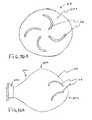
- FIG. 1schematically illustrates a lumen recanalization catheter system according to the present invention
- FIGS. 2A-2Cillustrate a method of recanalizing an obstructed lumen according to the present invention
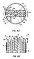
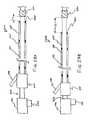
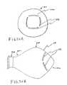
- FIGS. 3A and 3Bare transverse and longitudinal cross-sectional views, respectively, of a first embodiment of the distal portion of the catheter;
- FIGS. 4A and 4Bare transverse and longitudinal cross-sectional views, respectively, of a second embodiment of the distal portion of the catheter;
- FIGS. 5A and 5Bare transverse and longitudinal cross-sectional views, respectively, of the second embodiment of the distal portion of the catheter further illustrating the inflow of conductive liquid and aspiration of conductive liquid and gaseous products;
- FIGS. 6A and 6Bare transverse and longitudinal cross-sectional views, respectively, of a third embodiment of the distal portion of the catheter;
- FIGS. 7A and 7Bare transverse and longitudinal cross-sectional views, respectively, of a fourth embodiment of the distal portion of the catheter;
- FIGS. 8A and 8Bare transverse and longitudinal cross-sectional views, respectively, of a fifth embodiment of the distal portion of the catheter;
- FIGS. 9A and 9Bare transverse and longitudinal cross-sectional views, respectively, of a sixth embodiment of the distal portion of the catheter.
- FIGS. 10A and 10Bare transverse and longitudinal cross-sectional views, respectively, of a seventh embodiment of the distal portion of the catheter;
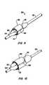
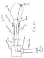
- FIGS. 11 and 12illustrate another embodiment of an electrosurgical catheter incorporating a radially expansible working end
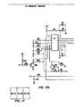
- FIG. 13is a block diagram of a power limiting device according to the present invention.
- FIG. 14is a graph of the power output of the power supply during normal operations and standby mode
- FIG. 15is a graph of the power output of the power supply in a low power, pulsatile mode
- FIGS. 16A-16Cshow various embodiments of a current sensor
- FIGS. 17A-Ceach show a circuit schematic of an exemplary embodiment of a power limiting device
- FIG. 18is a block diagram of a spark limiting device according to the present invention.
- FIG. 19is a chart of the current output of a spark limiting device according to the present invention.
- FIG. 20is a circuit schematic of an exemplary embodiment of a spark limiting device
- FIG. 21is a block diagram of the relationship between power limiting and spark limiting devices
- FIGS. 22A-Eshow a circuit schematic of both the power limiting and spark limiting devices
- FIG. 23illustrates a method of volumetrically removing media in a body passage having a total occlusion
- FIGS. 24A and 24Billustrate the volumetric removal of occlusive media in more detail
- FIG. 25is a longitudinal sectional view of an electrosurgical catheter, according to another embodiment of the invention.
- FIGS. 26A and 26Bare longitudinal sections of the distal end portion of a catheter showing a guidewire lumen with and without a guidewire, respectively;
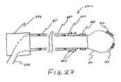
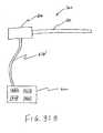
- FIG. 27shows a catheter including a fixed, external fluid delivery unit, according to one embodiment of the invention.
- FIGS. 28A , 28 Bshow a catheter including a moveable, external fluid delivery unit
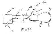
- FIG. 29shows a catheter having an internal fluid delivery unit
- FIG. 30illustrates a catheter having electrode leads coupled to a cable connector
- FIG. 31Aschematically represents a catheter handle having an integral catheter cable, according to one embodiment of the invention.
- FIG. 31Bschematically represents an electrosurgical system including a catheter coupled to a power supply via a catheter cable;
- FIG. 32shows an active loop electrode in communication with an electrically insulated electrode lead
- FIGS. 33A-B , 34 A-B, 35 A-B, and 36 A-Beach show an end view and a side view of active electrodes arranged on an electrode support, according to four different embodiments of the invention.
- FIG. 37Ashows an electrode gap between an active electrode and an electrode support
- FIG. 37Bshows an active electrode recessed within an electrode support having an electrode socket
- FIG. 37Cshows an active loop electrode arranged on a support distal end of an electrode support
- FIGS. 38A-Jeach show a cross-section of a loop portion of the active loop electrode of FIG. 37C , as seen along the lines 38 A-J of FIG. 37C ;
- FIGS. 39A and 39Billustrate a side view and an end view, respectively, of an electrode support having a fluid delivery channel therein;
- FIG. 40shows the distal end portion of a catheter having an insulating sleeve covering a return electrode, according to another embodiment of the invention.
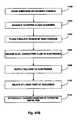
- FIG. 41Aschematically represents a series of steps involved a method of recanalizing a body passage, according to one embodiment of the invention
- FIG. 41Bschematically represents a series of steps involved a method of recanalizing a body passage, according to another embodiment of the invention.
- FIG. 42schematically represents a series of steps involved a method of making an electrosurgical catheter, according to a further embodiment of the invention.
- the present inventionrelates generally to the field of electrosurgery, and more particularly to surgical devices, systems and methods which employ high frequency electrical energy to remove or ablate tissue attached to implanted objects within the body.
- the systems and methods of the present inventionare particularly useful for removing atheromatous material which partially or fully occludes the body lumen, such as a blood vessel or for removing tissue or other material from the interior of stents or other implanted objects.
- body lumensthat may be treated by the method and apparatus of the present invention include the urinary tract (which for example may be occluded by an enlarged prostrate in males), the fallopian tubes (which may be occluded and cause infertility), and the like.
- the methods and apparatus disclosed hereinmay be used in a wide variety of procedures, including open procedures, intravascular procedures, urology, laparascopy, arthroscopy, thoracoscopy or other cardiac procedures, dermatology, orthopedics, gynecology, otorhinolaryngology, spinal and neurologic procedures, oncology and the like.
- proceduresincluding open procedures, intravascular procedures, urology, laparascopy, arthroscopy, thoracoscopy or other cardiac procedures, dermatology, orthopedics, gynecology, otorhinolaryngology, spinal and neurologic procedures, oncology and the like.
- the remaining disclosurewill be directed specifically to the removal of occlusive media within body lumens.
- the stenotic material in blood vesselswill be, by way of example but not limited to, atheroma or atheromatous plaque. It may be relatively soft (fresh) or it may be calcified and hardened.
- the inventionapplies energy selectively to the stenotic material to remove this material while limiting unwanted heating of the blood, the surrounding vessel wall and the stent anchored therein.
- the present inventionconfines the current flow paths between the return electrode and active electrodes to the vicinity of the tissue ablating region of the electrosurgical catheter. This confinement of current flow paths minimizes the undesired flow of current through the walls of the body passage, or through portions or all of the stent, which may otherwise induce non-specific tissue injury beyond the site of recanalization of the occluded lumen.
- high frequency (RF) electrical energyis applied to one or more active electrodes (usually in the presence of electrically conductive fluid) to remove and/or modify body structures, tissue, or occlusive media.
- active electrodesusually in the presence of electrically conductive fluid
- the present inventionmay be used to: (1) volumetrically remove occlusive media in a body passage; (2) volumetrically remove body structures (i.e., ablate or effect molecular dissociation of the structure); (3) cut or resect body structures; (4) vaporize, cauterize or desiccate structures and/or (5) coagulate and seal severed blood vessels.
- the occlusive mediais volumetrically removed or ablated.
- the high frequency voltage difference applied across the electrodesis sufficient to develop high electric field intensities in the vicinity of the occlusive media.
- the high electric field intensities adjacent the first conductor or active electrode(s)lead to electric field induced molecular breakdown of occlusive media through molecular dissociation (rather than thermal evaporation or carbonization).
- Applicantbelieves that the occlusive media is volumetrically removed through molecular disintegration of larger organic molecules into smaller molecules and/or atoms, such as hydrogen, oxygen, oxides of carbon, hydrocarbons and nitrogen compounds. This molecular disintegration completely removes the occlusive media, as opposed to dehydrating the tissue or occlusive media by the removal of water from the tissue or occlusive media, as is typically the case with electrosurgical desiccation and vaporization.
- the high electric field intensitiesmay be generated by applying a high frequency voltage that is sufficient to vaporize an electrically conductive fluid over at least a portion of the active electrode(s) in the region between the distal tip of the active electrode(s) and the occlusive media.
- the electrically conductive fluidmay be a liquid or gas, such as isotonic saline or blood, delivered to the target site, or a viscous fluid, such as a gel, applied to the target site. Since the vapor layer or vaporized region has a relatively high electrical impedance, it minimizes the current flow into the electrically conductive fluid. This ionization, under the conditions described herein, induces the discharge of energetic electrons and photons from the vapor layer and to the surface of the target media. A more detailed description of this phenomenon, termed Coblation® can be found in commonly assigned U.S. Pat. No. 5,697,882 the complete disclosure of which is incorporated herein by reference.
- Applicantbelieves that the principle mechanism of ablation in the Coblation® mechanism of the present invention is energetic electrons or ions that have been energized in a plasma adjacent to the active electrode(s).
- a liquidis heated enough that atoms vaporize off the surface faster than they recondense, a gas is formed.
- the gasis heated enough that the atoms collide with each other and knock their electrons off in the process, an ionized gas or plasma is formed (the so-called “fourth state of matter”).
- a more complete description of plasmacan be found in Plasma Physics, by R. J. Goldston and P. H. Rutherford of the Plasma Physics Laboratory of Princeton University (1995).
- the electron mean free pathincreases to enable subsequently injected electrons to cause impact ionization within these regions of low density (i.e., vapor layers or bubbles).
- the ionic particles in the plasma layerhave sufficient energy, they accelerate towards the target tissue.
- Energy evolved by the energetic electronse.g., 3.5 eV to 5 eV
- Plasmasmay be formed by heating gas and ionizing the gas by driving an electric current through it, or by transmitting radio waves into the gas.
- these methods of plasma formationgive energy to free electrons in the plasma directly, and then electron-atom collisions liberate more electrons, and the process cascades until the desired degree of ionization is achieved.
- the electronscarry the electrical current or absorb the radio waves and, therefore, are hotter than the ions.
- the electronswhich are carried away from the tissue towards the return electrode, carry most of the plasma's heat with them, allowing the ions to break apart the tissue molecules in a substantially non-thermal manner.
- the present inventionapplies high frequency (RF) electrical energy in an electrically conductive fluid environment to remove (i.e., resect, cut or ablate) the occlusive media.
- RFhigh frequency
- a high frequency power supplyis provided having an ablation mode, wherein a first voltage is applied to an active electrode sufficient to effect molecular dissociation or disintegration of the tissue, and a coagulation mode, wherein a second, lower voltage is applied to an active electrode (either the same or a different electrode) sufficient to achieve hemostasis of severed vessels within the tissue.
- an electrosurgical instrumenthaving one or more coagulation electrode(s) configured for sealing a severed vessel, such as an arterial vessel, and one or more active electrodes configured for either contracting the collagen fibers within the tissue or removing (ablating) the tissue, e.g., by applying sufficient energy to the tissue to effect molecular dissociation.
- the coagulation electrode(s)may be configured such that a single voltage can be applied to coagulate with the coagulation electrode(s), and to ablate with the active electrode(s).
- the power supplyis combined with the coagulation instrument such that the coagulation electrode is used when the power supply is in the coagulation mode (low voltage), and the active electrode(s) are used when the power supply is in the ablation mode (higher voltage).
- the Coblation® mechanism of the present inventioncan be manipulated to ablate or remove occlusive media, while having little effect on the surrounding body structures.
- the present inventionuses a technique of vaporizing electrically conductive fluid to form a plasma layer or pocket around the active electrode(s), and then inducing the discharge of energy from this plasma or vapor layer to break the molecular bonds of the occlusive media. Based on initial experiments, applicants believe that the free electrons within the ionized vapor layer are accelerated in the high electric fields near the electrode tip(s).
- the electron mean free pathincreases to enable subsequently injected electrons to cause impact ionization within these regions of low density (i.e., vapor layers or bubbles).
- Energy evolved by the energetic electronse.g., 4 to 5 eV
- the energy evolved by the energetic electronsmay be varied by adjusting a variety of factors, such as: the number of active electrodes; electrode size and spacing; electrode surface area; asperities and sharp edges on the electrode surfaces; electrode materials; applied voltage and power; current limiting means, such as inductors; electrical conductivity of the fluid in contact with the electrodes; density of the fluid; and other factors. Accordingly, these factors can be manipulated to control the energy level of the excited electrons. Since different tissue structures have different molecular bonds, the present invention can be configured to break the molecular bonds of certain tissue, while having too low an energy to break the molecular bonds of other tissue.
- fatty tissuee.g., adipose tissue
- the present inventionin its current configuration generally does not ablate or remove such fatty tissue.
- the present inventionmay be used to effectively ablate cells to release the inner fat content in a liquid form.
- factorsmay be changed such that these double bonds can also be broken in a similar fashion as the single bonds (e.g., increasing voltage or changing the electrode configuration to increase the current density at the electrode tips).
- a more complete description of this phenomenacan be found in co-pending U.S. patent application Ser. No. 09/032,375, filed Feb. 27, 1998 the complete disclosure of which is incorporated herein by reference.
- the present inventionapplies high frequency (RF) electrical energy in an electrically conductive fluid environment to remove (i.e., resect, cut or ablate) a body structure, occlusive media, or an occlusion within a body passage, lumen, orifice, or an in situ prosthesis.
- RFhigh frequency
- the electrosurgical instrument of this embodimentcomprises a shaft having a proximal end and a distal end which supports one or more active electrode(s).
- the shaftmay assume a wide variety of configurations, with the primary purpose being to mechanically support one or more active electrode(s) and permit the treating physician to manipulate the electrode(s) from a proximal end of the shaft.
- an electrosurgical catheter shaftwill be a narrow-diameter rod or tube, more usually having dimensions which permit it to be introduced through a cannula into the patient's body.
- the catheter shaftwill typically have a length of at least 5 cm for open procedures and at least 10 cm, more typically being 20 cm, or longer for endoscopic procedures.
- the catheter shaftwill typically have a diameter of at least 1 mm and frequently in the range from 1 mm to 10 mm.
- the shaftwill have any suitable length and diameter that would facilitate handling by the surgeon.
- the electrosurgical instrumentmay also be a catheter that is delivered percutaneously and/or endoluminally into the patient by insertion through a conventional or specialized guide catheter, a rapid exchange catheter, or a catheter having an active electrode or electrode array integral with its distal end.
- the catheter shaftmay be rigid or flexible, with flexible shafts optionally being combined with a generally rigid external tube for mechanical support. Flexible shafts may be combined with pull wires, shape memory actuators, and other known mechanisms for effecting selective deflection of the distal end of the shaft to facilitate positioning of the electrode or electrode array.
- the catheter shaftwill usually include a plurality of wires or other conductive elements running axially therethrough to permit connection of the electrode or electrode array and the return electrode to a connector at the proximal end of the catheter shaft.
- the catheter shaftmay include a guide wire for guiding the catheter to the target site, or the catheter may comprise a steerable guide catheter.
- the cathetermay also include a substantially rigid distal end portion to increase the torque control of the distal end portion as the catheter is advanced further into the patient's body.
- the cathetermay also include other internal lumens for providing separate functions, such as delivering fluid and aspirating products of ablation from the target site.
- the catheterwill have a fluid delivery lumen for delivering electrically conductive fluid to the target site.
- the cathetermay have an aspiration lumen coupled to a vacuum source for aspirating non-condensable gases and other products of ablation from the site.
- the cathetermay also include an isolation system for fluidly isolating the region around the target site.
- the isolation systemincludes proximal and distal balloons that are movable to portions of the body passage proximal and distal to the region of the target site.
- the distal balloonby way of example, may be formed on a hollow guide wire that is fluidly coupled to an inflation source, such as a syringe.
- the proximal balloonfor example, may be coupled to the catheter body proximal to the active and return electrodes.
- the inventiontypically includes guiding apparatus for guiding the catheter along a pathway approximating the central region of the occluded blood vessel.
- the guiding apparatusis usually an electrically conducting wire that may serve as the return electrode.
- the electrically conducting wireis extensible from the distal tip of the catheter and is located within and concentric to the catheter conveniently being in the form of a movable or fixed guidewire, usually being a movable guidewire.
- the active electrode(s)are preferably supported within or by an electrically insulating spacing structure, such as silicone, urethane, Teflon, polyimide, or similar material, which is positioned near the distal end of the instrument shaft.
- the return electrodemay be either integral with the instrument shaft, or may be on another instrument located in close proximity to the distal end of the catheter shaft.
- the proximal end of the catheterwill include the appropriate electrical connections for coupling the return electrode(s) and the active electrode(s) to a high frequency power supply, such as an electrosurgical generator.
- One or more insulatorswill be positioned around the return electrode to insulate the return electrode from the electrically conductive fluid and the patient's body.
- a current flow pathmay be generated by submerging the tissue site in an electrically conductive fluid (e.g., within a viscous fluid, such as an electrically conductive gel) or by directing an electrically conductive fluid along a fluid path to the target site (i.e., a liquid, such as isotonic saline, hypotonic saline; or a gas, such as argon).
- the conductive gelmay also be delivered to the target site to achieve a slower more controlled delivery rate of conductive fluid.
- the viscous nature of the gelmay allow the surgeon to more easily contain the gel around the target site (e.g., rather than attempting to contain isotonic saline).
- a liquid electrically conductive fluide.g., isotonic saline
- a liquid electrically conductive fluidmay be used to concurrently “bathe” the target tissue surface to provide an additional means for removing any tissue, and to cool the region of the target tissue ablated in the previous moment.
- the power supplymay include a fluid interlock for interrupting power to the active electrode(s) when there is insufficient conductive fluid around the active electrode(s). This ensures that the instrument will not be activated when conductive fluid is not present, minimizing the tissue damage that may otherwise occur.
- a fluid interlockfor interrupting power to the active electrode(s) when there is insufficient conductive fluid around the active electrode(s).
- the system of the present inventionmay include one or more suction lumen(s) in the instrument, or on another instrument, coupled to a suitable vacuum source for aspirating fluids from the target site.
- the inventionmay include one or more aspiration electrode(s) coupled to the distal end of the suction lumen for ablating, or at least reducing the volume of, non-ablated tissue fragments that are aspirated into the lumen.
- the aspiration electrode(s)function mainly to inhibit clogging of the lumen that may otherwise occur as larger tissue fragments are drawn therein.
- the aspiration electrode(s)may be different from the ablation active electrode(s), or the same electrode(s) may serve both functions.
- each individual active electrode in the electrode arrayis electrically insulated from all other active electrodes in the array within said instrument and is connected to a power source which is isolated from each of the other active electrodes in the array or to circuitry which limits or interrupts current flow to the active electrode when low resistivity material (e.g., blood, electrically conductive saline irrigant or electrically conductive gel) causes a lower impedance path between the return electrode and the individual active electrode.
- the isolated power sources for each individual active electrodemay be separate power supply circuits having internal impedance characteristics which limit power to the associated active electrode when a low impedance return path is encountered.
- the isolated power sourcemay be a user selectable constant current source.
- a single power sourcemay be connected to each of the active electrodes through independently actuatable switches, or by independent current limiting elements, such as inductors, capacitors, resistors and/or combinations thereof.
- the current limiting elementsmay be provided in the instrument (catheter), connectors, cable, power supply, or elsewhere along the conductive path from the power supply to the distal end of the instrument.
- the resistance and/or capacitancemay occur on the surface of the active electrode(s) due to oxide layers which form selected active electrodes (e.g., titanium or a resistive coating on the surface of metal, such as platinum).
- the spacing structure and the fluid outletmay be recessed from an outer surface of the instrument or handpiece to confine the electrically conductive fluid to the region immediately surrounding the spacing structure.
- the shaftmay be shaped so as to form a cavity around the spacing structure and the fluid outlet. This helps to assure that the electrically conductive fluid will remain in contact with the active electrode(s) and the return electrode(s) to maintain the conductive path therebetween. In addition, this will help to maintain a vapor layer and subsequent plasma layer between the active electrode(s) and the occlusive media at the treatment site throughout the procedure, which reduces the thermal damage to the lumen that might otherwise occur if the vapor layer were extinguished due to a lack of conductive fluid. Provision of the electrically conductive fluid around the target site also helps to maintain the temperature of the target site at desired levels.
- the active electrodesare spaced from the occlusive media a sufficient distance to minimize or avoid contact between the occlusive media and the vapor layer formed around the active electrodes.
- contact between the heated electrons in the vapor layer and the occlusive mediais minimized as these electrons travel from the vapor layer back through the conductive fluid to the return electrode.
- the ions within the plasmawill have sufficient energy, under certain conditions such as higher voltage levels, to accelerate beyond the vapor layer to the occlusive media.
- the molecular bondsare dissociated or broken as in previous embodiments, while minimizing the electron flow, and thus the thermal energy, in contact with the occlusive media.
- the electrical conductivity of the electrically conductive fluid(in units of milliSiemens per centimeter or mS/cm) will usually be greater than 0.2 mS/cm, preferably greater than 2 mS/cm and more preferably greater than 10 mS/cm.
- the electrically conductive fluidis isotonic saline, which has a conductivity of about 17 mS/cm. Applicant has found that a more conductive fluid, or one with a higher ionic concentration, will usually provide a more aggressive ablation rate.
- a saline solution with higher levels of sodium chloride than isotonic saline(which is on the order of about 0.9% sodium chloride) e.g., on the order of greater than 1% or between about 3% and 20%, may be desirable.
- the inventionmay be used with different types of conductive fluids that increase the power of the plasma layer by, for example, increasing the quantity of ions in the plasma, or by providing ions that have higher energy levels than sodium ions.
- the present inventionmay be used with electrically conductive fluids comprising elements other than sodium, such as potassium, magnesium, calcium and other metals on the left side of the Periodic Table (e.g., elements in Groups IA and IIA).
- electronegative elementsmay be used in place of chlorine, such as fluorine.
- a frequency of about 100 kHzis useful because the tissue impedance is much greater at this frequency as compared with a frequency of about 500 kHz.
- higher frequenciesmay be desirable (e.g., 400-600 kHz) to minimize low frequency current flow into the heart or the nerves of the head and neck.
- the voltage difference applied between the return electrode(s) and the active electrode(s)will be at high or radio frequency, typically between about 5 kHz and 20 MHz, usually being between about 30 kHz and 2.5 MHz, preferably being between about 50 kHz and 500 kHz, more preferably less than 350 kHz, and most preferably between about 100 kHz and 200 kHz.
- the RMS (root mean square) voltage appliedwill usually be in the range from about 5 volts to 1000 volts, preferably being in the range from about 10 volts to 500 volts depending on the active electrode size, the operating frequency and the operation mode of the particular procedure or desired effect on the tissue (i.e., contraction, coagulation or ablation).
- the voltagewill usually be in the range of about 100 Vrms to 300 Vrms.
- the peak-to-peak voltagewill be in the range of 10 volts to 2000 volts and preferably in the range of 20 volts to 500 volts and more preferably in the range of about 40 volts to 450 volts (again, depending on the electrode size, the operating frequency and the operation mode).
- the voltageis usually delivered in a series of voltage pulses or alternating current of time varying voltage amplitude with a sufficiently high frequency (e.g., on the order of 5 kHz to 20 MHz) such that the voltage is effectively applied continuously (as compared with e.g., lasers claiming small depths of necrosis, which are generally pulsed at about 10 Hz to 20 Hz).
- the duty cyclei.e., cumulative time in any one-second interval that energy is applied
- the preferred power source of the present inventiondelivers a high frequency current selectable to generate average power levels ranging from several milliwatts to tens of watts per electrode, depending on the volume of target tissue being heated, and/or the maximum allowed temperature selected for the probe tip.
- the power sourceallows the user to select the voltage level according to the specific requirements of a particular cardiac surgery, arthroscopic surgery, dermatological procedure, ophthalmic procedures, open surgery or other endoscopic surgery procedure.
- the power sourcemay have an additional filter, for filtering leakage voltages at frequencies below 100 kHz, particularly voltages around 60 kHz.
- a description of a suitable power sourcecan be found in U.S. Provisional Application No. 60/062,997, filed on Oct. 23, 1997, the full disclosure of which is incorporated herein by reference.
- the power sourcemay be current limited or otherwise controlled so that undesired heating of the target tissue or surrounding (non-target) tissue does not occur.
- current limiting inductorsare placed in series with each independent active electrode, where the inductance of the inductor is in the range of 10 uH to 50,000 uH, depending on the electrical properties of the target tissue, the desired tissue heating rate and the operating frequency.
- capacitor-inductor (LC) circuit structuresmay be employed, as described previously in U.S. Pat. No. 5,697,909, the complete disclosure of which is incorporated herein by reference. Additionally, current limiting resistors may be selected.
- these resistorswill have a large positive temperature coefficient of resistance so that, as the current level begins to rise for any individual active electrode in contact with a low resistance medium (e.g., saline irrigant or blood), the resistance of the current limiting resistor increases significantly, thereby minimizing the power delivery from the active electrode into the low resistance medium (e.g., saline irrigant, blood).
- a low resistance mediume.g., saline irrigant or blood
- the power supply or controlleris “tuned” so that it will not apply excessive power to the blood (e.g., in the ventricle), once it crosses the wall of the heart and enters the chamber of the left ventricle. This minimizes the formation of a thrombus in the heart (i.e., will not induce thermal coagulation of the blood).
- the power supplymay include an active or passive architecture, and will typically include a mechanism for sensing resistance between a pair(s) of active electrodes at the distal tip, or between one or more active electrodes and a return electrode, to sense when the electrode array has entered into the blood-filled chamber of the left ventricle.
- an ultrasound transducer at the tip of the probecan be used to detect the boundary between the wall of the heart and the blood filled left ventricle chamber, turning off the electrode array just as the probe crosses the boundary.
- the inventionis not limited to electrically isolated active electrodes, or even to a plurality of active electrodes.
- the array of active electrodesmay be connected to a single lead that extends through the catheter shaft to a power source of high frequency current.
- the cathetermay incorporate a single electrode that extends directly through the catheter shaft or is connected to a single lead that extends to the power source.
- the active electrode(s)may have ball shapes (e.g., for tissue vaporization and desiccation), twizzle shapes (for vaporization and needle-like cutting), spring shapes (for rapid tissue debulking and desiccation), twisted metal shapes, annular or solid tube shapes or the like.
- the electrode(s)may comprise a plurality of filaments, rigid or flexible brush electrode(s) (for debulking a tumor, such as a fibroid, bladder tumor or a prostate adenoma), side-effect brush electrode(s) on a lateral surface of the shaft, coiled electrode(s) or the like.
- an electrosurgical cathetercomprises a single active electrode that extends from an insulating member, e.g., ceramic, at the distal end of the shaft.
- the insulating memberis preferably a tubular structure that separates the active electrode from a tubular or annular return electrode positioned proximal to the insulating member and the active electrode.
- the catheterincludes a single active electrode that can be rotated relative to the rest of the catheter body, or the entire catheter may be rotated relative to the body lumen.
- FIG. 1shows a lumen recanalization catheter system 2 constructed according to the principles of the present invention.
- Catheter system 2generally comprises an electrosurgical catheter 6 connected to a power supply 80 by an interconnecting cable 86 for providing high frequency voltage to a target tissue and an irrigant reservoir or source 100 for providing electrically conductive fluid to the target site.
- Catheter 6generally comprises an elongate, flexible shaft body 12 including a tissue ablating region 8 at the distal end of body 12 , and a proximal balloon 40 positioned on body 12 proximal to region 8 .
- a guide wire 28(which may also serve as a return electrode) includes a distal balloon 18 which may be axially translated relative to region 8 and proximal balloon 40 , as discussed in further detail below.
- the proximal portion of catheter 6includes a multi-lumen fitment 114 which provides for interconnections between lumens and electrical leads within catheter 6 and conduits and cables proximal to fitment 114 .
- a catheter electrical connector 96is removably connected to a distal cable connector 94 which, in turn, is removably connectable to generator 80 through connector 92 .
- One or more electrically conducting lead wires (not shown) within catheter 6extend between one or more active electrodes at tissue ablating region 8 and one or more corresponding electrical terminals (also not shown) in catheter connector 96 via active electrode cable branch 87 .
- hollow guide wire 28functions as the return electrode, and is electrically attached within a contact housing 111 by a sliding electrical contact (not shown).
- a return electrode cable branch 89couples the sliding electrical contact to catheter connector 96 .
- Electrical leads within cable 86allow connection between terminals corresponding to return electrode 28 and one or more active electrodes 32 (e.g., FIG. 2A ) in distal cable connector 94 and power supply 80 .
- Power supply 80has an operator controllable voltage level adjustment 82 to change the applied voltage level, which is observable at a voltage level display 84 .
- Power supply 80also includes a foot pedal 88 and a cable 90 which is removably coupled to power supply 80 for remotely adjusting the energy level applied to active electrodes 32 .
- power supply 80includes three such foot pedals (not shown), wherein the first foot pedal is used to place the power supply into the “ablation” mode and the second foot pedal places power supply 80 into the “subablation” mode. The third foot pedal allows the user to adjust the voltage level within the “ablation” mode.
- a sufficient voltageis applied to the active electrodes to establish the requisite conditions for molecular dissociation of the tissue (i.e., vaporizing a portion of the electrically conductive fluid, and ionizing charged particles within the vapor layer).
- the requisite voltage level for ablationwill vary depending on the number, size, shape and spacing of the electrodes, the distance to which the electrodes extend from the support member, etc.
- the power supply 80applies a low enough voltage to the active electrodes to avoid vaporization of the electrically conductive fluid and subsequent molecular dissociation of the tissue.
- the surgeonmay automatically toggle the power supply between these modes by alternatively stepping on the foot pedals. This allows the surgeon to quickly move between subablation (e.g., coagulation) and ablation in situ, without having to remove his/her concentration from the surgical field or without having to request an assistant to switch the power supply.
- the power supply of the present inventionmay include power limiting devices to protect attached electrosurgical catheters from excessive power delivery and to sustain controlled operation of the catheter or instrument.
- Poweris the time rate of transferring or transforming energy, and for electricity, power is measured in watts, where one watt is the power to create energy at the rate of one joule per second.
- a power limiting device 300is designed to reduce the power drawdown from the power supply when an attached device, such as a monopolar or bipolar surgical instrument, is not engaging body tissue or draws excessive power. For example, excessive power is delivered from the power supply if the RF catheter is in saline or blood and is not engaging target media.
- Device 300conveniently conserves power supplied to the catheter without completely deactivating the power supply or requiring the user to manually reduce power. Excessive power draw will overheat the power supply and corrupt power supply performance. Device 300 also acts as a safety feature by reducing the stray emission of energy when the catheter is in transit through the body to a target site.
- the power limiting device 300operates on a continuous basis to detect excessive power output.
- the device 300is responsive to the “total power” delivered by the power supply.
- FIG. 14illustrates the power output of the power supply when an excessive power is detected.
- Device 300limits the overall output power from the power supply to be lower than about 240-360 watts, preferably less than about 300 watts.
- the device 300then operates on a duty cycle or periodic detection cycle 301 between about 50 and 300 ms, where the device 300 checks every cycle to determine if it is safe to resume power output.
- the device 300has a fixed duty cycle wave form and includes a fixed periodical pulsing circuit which is about 10 ms on and 90 ms off. Once the fault condition is gone, power output returns to operating levels.
- the device 300uses a current sensor 302 attached to the output electrodes to derive the power output of the power supply.
- the current limitwhich may be set at any desired level, is about 5 amps for a 300 watt power limit when voltage is set at about 60V.
- the device 300reduces the output of the power supply to a standby mode. Once in standby mode, the power supply preferably has a pulsatile power output. As shown in FIG., the device 300 allows the current output to be activated during each duty cycle to determine if the power supply may return to normal operation.
- the pulsatile power outputmay be described as shown in FIG. 15 .
- the duty cycleis about 10-15 ms on, preferably about 12 ms on, and about 85-90 ms off, preferably about 88 ms off. This creates a cycle of about 100 ms, during which time, power is increased and then reduced if the probe senses that it is not in the vicinity of body tissue or other higher impedance material.
- This sensing stepis the initial portion of the duty cycle where current is activated for a period of time, described as being between 10-15 ms. If current again reaches the 5 amp level or some other predetermined level, the output is reduced and the device 300 waits for the next duty cycle.
- the total power output during this short periodis only about 10 watts. However, the current output is sufficient to show that the fault condition still exists.
- the device 300tests for potentially excessive power output with a fault condition that occurs without actually reaching the power level against which the device is protecting. This pulsatile power output continues until power drawdown returns to within acceptable ranges (FIG. 14 ).
- the power limiting featurereduces power output on a fault condition that is current based (so long as there is constant voltage).
- the power limiting device 300 in the standby modechecks the impedance (instead of current) encountered by the probe every 100 ms or over some other interval selected by the user. As long as the instrument is in a low impedance environment and impedance is below a predetermined level, the power supply will operate in the pulsatile mode, never fully activating to therapeutic power levels such as for ablation or coagulation. The low impedance is indicative of a potential over power scenario.
- the device 300may check the impedance over variable time intervals that change as desired. When the instrument reaches a target site or comes in the vicinity of higher impedance tissue, in one embodiment, a higher impedance is noted by a drop in current draw (i.e.
- the power limiting device 300will continue to check the impedance encountered every duty cycle.
- a preferred embodiment of the device 300comprises of at least one current sensor 302 detecting the current output from DC/DC converter 304 .
- the current sensor 302may be configured as one sensor for one electrode or one sensor for a plurality of electrodes. In the present embodiment, one sensor 302 is used for six electrodes on the probe, although more preferably one sensor is used for three electrodes.
- the sensors 302(noted as T 1 , T 4 , T 5 , etc.) are configured to wrap around the electrodes as shown in FIG. 16 . Signals from sensors 302 are passed through a plurality of rectifying diodes and capacitors which filter and condition the typically analog signal from the current sensor. In the block diagram of FIG.
- these diodes and componentsare represented by signal conditioner 306 .
- the conditioned signal from the sensor 302is then passed to a level detector or voltage comparator 308 .
- the comparator 308determines if the current output has exceeded the predetermined threshold level.
- a regulator or logic unit 310determines power of output driver 312 based on the value of the output current compared to a predetermined current value. In the standby or power limited mode, the logic unit 310 of the device 300 will preferably duty cycle the output from output driver 312 .
- the logic unit 310is preferably an integrated circuit such as a Field Programmable Gate Array (FPGA) to maximize cost efficiency, it should be understood that other devices such as computers or microprocessors may also be used to perform the required logic functions.
- FPGAField Programmable Gate Array
- FIGS. 17A-Cshow an exemplary embodiment of power limiting device 300 .
- the circuit diagramshows that overcurrent is sensed by T 5 . It is rectified and filtered by D 16 , D 17 , D 18 , D 19 , R 33 , and C 19 etc.
- the rectified and filtered signalsare fed into voltage comparator 308 which determines if power threshold has been reached.
- the output of voltage comparator 308is fed into the FPGA which controls the power supply to the power limiting mode (e.g. it turns on DC/DC converter 10 ms on and 90 ms off).
- Device 300includes a converter of a full-wave bridge arrangement with all four switching elements driven by a single transformer.
- Cycle-by-cycle current limit controlis applied by the FPGA removing the gate drive.
- the inverterruns at a fixed 50% duty cycle whenever drive (of about 100 kHz or other) from the FPGA is available.
- the inverteris running at zero voltage switching mode to reduce EMI and indirectly reduces leakage current.
- the power supply of the present inventionmay also include a spark limiting device 330 ( FIG. 18 ) to prevent sudden current spikes which may char or otherwise damage the electrosurgical instrument and surgical target site.
- a spark limiting device 330FIG. 18
- the power supply of the present inventionmay also include a spark limiting device 330 ( FIG. 18 ) to prevent sudden current spikes which may char or otherwise damage the electrosurgical instrument and surgical target site.
- a spark limiting device 330FIG. 18
- the power supply of the present inventionmay also include a spark limiting device 330 ( FIG. 18 ) to prevent sudden current spikes which may char or otherwise damage the electrosurgical instrument and surgical target site.
- the impedance encountered by the instrumentdecreases suddenly and this undesirably draws a large amount of current from the power supply.
- This sudden current increasemay create sparks between the probe and the metal object.
- the large amount of current passing through the probewill likely char items along the electrical pathway and may melt electrodes on the electrosurgical instrument.
- the spark limiting device 330will reduce current output to zero when an extremely low impedance source such as a metal screw or a metal cannula or stent creates a high current drawdown.
- the spark limiting device 330is located close to the output electrode. This reduces the delay of the device 330 and allows the device to respond more quickly.
- the spark limiting device 330is directed to reduce current output to prevent sparking, not total power output.
- the block diagram of FIG. 18appears similar to that of the power limiting device 300 (FIG. 13 ), the spark limiting device 330 is not a fixed periodical pulsing circuit of the type described with reference to FIG. 17 .
- the spark limiting device 330preferably processes continuous signals, such as analog signals, from the current sensor 332 .
- the spark limiting device 330continuously monitors current fluctuations of the power output of converter 334 (typically an AC/DC converter).
- the continuous flow of signal in the spark limiting device 330allows it to detect the sudden increase in current almost instantaneously and almost certainly before the isolated, power limiting device 300 .
- Current outputis preferably turned off after an overcurrent is detected.
- the current output during normal therapeutic operationmay be in the range of 0.2 amperes or less.
- the spark limiting device 330preferably interrupts output when current exceeds about 1.0 to 3.0 amperes. These current levels are insufficient to cause sparking, but enough to warrant concern over potential sparking. When current exceeds levels higher than those stated, the device 330 will preferably prevent any current output from the instrument.
- the output of the power supplyis similar to that shown in FIG. 19 .
- the spark limiting device 330has a built-in delay device that turns off current output for a duration of 2-90 ms. Preferably, the delay is programmed into the FPGA.
- the device 330will allow current to flow through the probe, albeit at extremely low power, to detect if the extremely low impedance state still exists. If current again exceeds the threshold level of about 1.0 to 3.0 amperes (FIG. 19 ), the device 330 will zero the output of the power supply and pause for the built-in delay. This delay acts in some ways to give the spark limiting device 330 a duty cycle-like operation.
- the power supplydoes not shutoff. This is a particularly useful feature in that it eliminates down time associated with restarting the power supply from poweroff.
- the spark limiting device 330will allow power to flow from the RF probe as usual. Preferably, as long as the probe is exposed to the low impedance source, the device 330 will not allow power to be transmitted.
- the block diagram of FIG. 18shows that the spark limiting device 330 includes a signal conditioner 336 , a level detector 338 , a regulator or logic unit 340 , and an output driver 342 (such as an RF source known in the art).
- a signal conditioner 336receives the signal from the spark limiting device 330 and the signal conditioner 336 .
- the logic unit 340 , level detector 338 , and signal conditioner 336may all be combined into a single device or processor as indicated by the dotted line 344 . The same may also apply to the power limiting device 300 which has components that may be integrated together. Referring to FIG.
- the current sensors 332are denoted by elements T 8 , T 9 , T 12 , and T 13 .
- the diodes D 36 -D 76 and resistors/capacitors R 131 -R 133 /C 73 etc.are used to condition the analog signal to remove noise and other undesirable qualities.
- a voltage comparator U 8 D and the FPGA, corresponding to level detector 338 and logic device 340are used to determine if the output current detected by sensor 332 is above a predetermined level.
- the power limiting device 300 and the spark limiting device 330may be used individually, it is understood that the two devices may also be used concurrently in the power supply.
- the power supply of the present inventionhas the power limiting device 300 and the spark limiting device 330 arranged in a serial configuration as shown in FIGS. 21 , 22 A-E. This configuration provides for the circuit isolation mandated by safety regulations for medical device power supplies. As shown in FIG. 21 , the power supply has P/O primary isolation, P/O secondary isolation, and patient isolation. Using devices 300 and 330 also provides protection for both converters (DC/DC and DC/AC) used to provide stability of the power output.
- the spark limiting device 330is typically located closer to the electrode output while the power limiting device 300 is more isolated from the electrode output.
- the additional amount of isolation circuitryintroduces a lag time into the responsiveness of the power limiting device.
- one devicereacts slower while the device closer to the electrode reacts faster.
- the spark limiting device 330activates to reduce the current output from the power supply to zero.
- the current outputmay be reduced to some nonzero value so long as sparks are not generated.
- the spark limiting device 330introduces a delay and then checks to see if it can power up. During this time, the power limiting device 300 also continues to check about every duty cycle to see if power should be increased. In one embodiment, the power limiting device 300 introduces more delay into the system since its duty cycle is longer than the 2-90 ms delay of the spark limiting device 330 .
- the proberesumes normal operations. If the catheter is no longer in contact with target tissue, then the power supply will most likely be in pulsatile mode while awaiting to be repositioned.
- conductive fluid 30is provided to tissue ablation region 8 of catheter 6 via a lumen (not shown in FIG. 1 ) within catheter 6 .
- Fluid 30is supplied to the lumen from the source 100 along a conductive fluid supply line 102 and a conduit 103 , which is coupled to the inner catheter lumen at multi-lumen fitment 114 .
- the source of conductive fluide.g., isotonic saline
- a control valve 104may be positioned at the interface of fluid supply line 102 and conduit 103 to allow manual control of the flow rate of electrically conductive fluid 30 .
- a metering pump or flow regulatormay be used to precisely control the flow rate of the conductive fluid.
- System 2further includes an aspiration or vacuum system (not shown) to aspirate liquids and gases from the target site, as well as syringes 106 , 108 for inflating distal and proximal balloons 18 , 40 , respectively.
- an aspiration or vacuum system(not shown) to aspirate liquids and gases from the target site
- syringes 106 , 108for inflating distal and proximal balloons 18 , 40 , respectively.
- syringe 106is provided at the proximal end of guide wire 28 for inflating distal balloon 18 , as shown by translation vectors 116 , 118 .
- guidewire 28can be advanced or retracted relative to tissue ablation region 8 of catheter 6 as shown by translation vectors 116 , 118 such that, for each increment of relative displacement 116 at the proximal end of catheter 6 , there is a corresponding displacement 118 of the hollow guidewire 28 relative to the tissue ablating region 8 of catheter 6 .
- tissue ablating region 8 of catheter 6progresses through occlusive media 14 , such as atheromatous media or thrombus within a body lumen 10 , e.g., a blood vessel.
- occlusive media 14such as atheromatous media or thrombus within a body lumen 10 , e.g., a blood vessel.
- the principles of the present inventionare also applicable to any body lumen which becomes partially or totally occluded.
- the present inventionis particularly useful in a lumen containing a lumenal prosthesis, such as a stent 16 , stent-graft or graft, which may be metallic, non-metallic, or a non-metallic coated metallic structure.
- a particular advantage of the present inventionis the confinement of current flow paths (not shown) between the return electrode (hollow guide wire 28 in the present example) and one or more active electrodes 32 to the vicinity of tissue ablating region 8 .
- This confinement of current flow pathsminimizes the undesired flow of current through portions or all of stent 16 , which may otherwise induce non-specific tissue injury beyond the site of recanalization of the occluded lumen 10 .
- tissue ablating region 8 of catheter 6is positioned proximal to the occlusive media 14 within lumen 10 .
- the distal region of hollow guide wire 28is positioned distal to the occlusive media 14 either before or after the initial positioning of tissue ablation region 8 .
- proximal balloon 40(not shown in FIG. 2A ) is inflated to effect a seal between catheter shaft 42 and interior wall 12 of lumen 10 to minimize the flow of bodily fluid 26 (e.g., blood) from regions proximal to the tissue ablating region 8 of catheter 6 .
- Electrically conductive and biologically compatible fluid 30(e.g., isotonic saline) is delivered into lumen 10 for a sufficient period of time and under a sufficient positive pressure to displace naturally occurring bodily fluid 26 in the region between the tissue ablating region and the distal tip of guide wire 28 .
- distal balloon 18can be inflated to effect a seal between balloon 18 and the interior wall 12 of lumen 10 .
- the supply of electrically conductive fluid 30is continuously delivered to region 8 and may be balanced with the aspiration of fluid from the site of intended recanalization.
- the active electrode(s) 32is (are) then energized by applying a high frequency voltage between active electrode(s) 32 and return electrode or guide wire 28 .
- a high electric fieldis created at the surface of active electrode(s) 32 which causes the volumetric removal or ablation or target tissue in close proximity with active electrode(s) 32 .
- the flow of electrical current between return electrode 28 and active electrode(s) 32is shown by current flux lines 62 in FIG. 2 B.
- gaseous productsare generated (not shown) which are entrained in the electrically conductive fluid 30 and removed through aspiration lumen 58 (not shown in FIGS. 2A , 2 B).
- the current flux lines 62are generally confined to the central portion of tissue ablation region 8 because they generally flow inward towards return electrode 28 and because the occlusive media 14 generally shields the outer region of lumen (including stent 16 ) from flux lines 62 . This minimizes undesirable interaction between the electrical current and stent 16 .
- this ablation procedureis continued until the desired length of the lumen containing occlusive media is recanalized.
- the products of ablationare confined between proximal balloon 40 and distal balloon 18 to minimize, for example, the injection of any non-condensable gaseous products of ablation into the blood stream which could otherwise lead to the formation of injurious or life-threatening emboli.
- the occlusive media 14has been volumetrically removed (i.e., ablated)
- the energy applicationis suspended, the valve on the aspiration lumen is closed, control valve 104 is closed and balloons 18 , 40 are deflated.
- the time period from the initial inflation of balloons 18 , 40 to the deflation of these balloonsis typically about 15-45 seconds, depending on the length and the extent of occlusion in the vessel.
- the above processmay be repeated several times with intervals of no balloon inflation so that vital oxygen-bearing blood can be reperfused through the zone of intended recanalization to preserve the tissue distal to the recanalization zone.
- FIGS. 3A and 3BA first embodiment of tissue ablation region 8 of catheter 6 is shown in FIGS. 3A and 3B .
- two active electrodes 50 a and 50 bare secured within an electrically insulating support member 34 .
- the electrodes 50 a , 50 bare preferably composed of a refractory, electrically conductive metal or alloy, such as platinum, titanium, tantalum, tungsten, stainless steel, gold-plated, copper, nickel, and the like.
- the support member 34is secured to the distal end of catheter 6 with a biocompatible adhesive 60 between support member 34 and outer sleeve 36 .
- An electrically insulating sleeve 54preferably extends above the distal plane of active electrodes 50 a , 50 b by a distance H s .
- a central lumen in support member 34provides a passageway for guide wire 28 that permits axial displacement and rotation of tissue ablating region 8 relative to guide wire 28 .
- the support member 34will comprise an inorganic insulator, such as ceramic, glass, glass/ceramic or a high resistivity material, such as silicone or the like.
- An inorganic materialis generally preferred for the construction of the support member 34 since organic or silicone based polymers are known to rapidly erode during sustained periods of the application of high voltages between electrodes 50 a , 50 b and the return electrode 28 during tissue ablation.
- organic or silicone based polymersmay be used without significant erosion and loss of material of the support member 34 and, therefore, without significant reduction in ablation performance.
- an irrigation lumen 56 and an aspiration lumen 58are provided to inject electrically conductive fluid 30 and remove gaseous products of ablation 48 from the site of recanalization.
- An additional fluid lumen 57provides fluid communication between inflation syringe 108 and proximal balloon 40 .
- This fluid lumen 57is filled with a sealant in those portions of the catheter distal to proximal balloon 40 .
- the fluid lumen 57may terminate within the proximal balloon 40 .
- catheter 6is rotated approximately 180 degrees clockwise and then approximately 180 degrees counter clockwise as the electrodes 50 a , 50 b are energized by power supply 80 ( FIG. 1 ) to effect ablation of the occlusive media.
- power supply 80FIG. 1
- Using a reciprocating rotational motion combined with a small amount of pressure in the longitudinal direction to advance tissue ablation region 8 through the longitudinal length of the occlusive media 14allows recanalization of the occluded vessel as described with reference to FIGS. 2A-2C .
- the cross-sectional shape of the active electrodesmay be round wires as shown in FIG. 3B , or they may have shaped surfaces to enhance the electric field intensity at the distal surfaces of the active electrodes 50 a , 50 b .
- Suitable electrode designs for use with the present inventionmay be found in co-pending, commonly assigned application Ser. No. 08/687,792, filed Jul. 19, 1996, the complete disclosure of which is incorporated herein by reference for all purposes.
- Return electrode 28comprises an electrically conducting material, usually a metal, which is selected from the group consisting of stainless steel alloys, platinum or its alloys, titanium or its alloys, molybdenum or its alloys, and nickel or its alloys.
- the return electrode 28may be composed of the same metal or alloy which forms the active electrodes 50 a , 50 b to minimize any potential for corrosion or the generation of electrochemical potentials due to the presence of dissimilar metals contained within an electrically conductive fluid 30 , such as isotonic saline (discussed in greater detail below).
- FIGS. 4A and 4Ba second embodiment of tissue ablation region 8 of catheter 6 will now be described.
- four active electrodes 32 a , 32 b , 32 c , 32 dare secured within an electrically insulating support member 34 .
- support member 34is secured to the distal end of catheter 6 with a biocompatible adhesive 60 between support member 34 and outer sleeve 36 .
- An electrically insulating sleeve 54preferably extends above the distal plane of active electrodes 50 a , 50 b by a distance H s .
- a central lumen in support member 34provides a passageway for guide wire 28 that permits axial displacement and rotation of tissue ablating region 8 relative to guide wire 28 .
- an irrigation lumen 56 and an aspiration lumen 58are provided to inject electrically conductive fluid 30 and remove gaseous products of ablation 48 from the site of recanalization.
- An additional fluid lumen 57provides fluid communication between inflation syringe 108 and proximal balloon 40 . This fluid lumen 57 is filled with a sealant, or terminates, in those portions of the catheter distal to proximal balloon 40 .
- catheter 6is rotated approximately 180 degrees clockwise and then approximately 180 degrees counter clockwise as the electrodes 32 are energized by generator 80 ( FIG. 1 ) to effect ablation of the occlusive media.
- generator 80FIG. 1
- Using a reciprocating rotational motion combined with a small amount of pressure to advance tissue ablation region 8 through the longitudinal length of the occlusive media 14allows recanalization of the occluded vessel as described with reference to FIGS. 2A-2C .
- the cross-sectional shape of the active electrodesmay be round wires as shown in FIG. 4B , or they may have shaped surfaces to enhance the electric field intensity at the distal surfaces of the active electrodes 32 as described co-pending, commonly assigned application Ser. No. 08/687,792, filed Jul. 19, 1996 the complete disclosure of which has previously been incorporated herein by reference.
- FIGS. 4A and 4BThe embodiment of FIGS. 4A and 4B is illustrated in greater detail in FIGS. 5A and 5B .
- electrically conductive fluidflows through irrigation lumen 56 of catheter 6 to and through irrigation port 44 and subsequently surrounds the target site (i.e., occlusive media 14 ).
- a vapor layer 64forms at and around active electrodes 32 a-d with concomitant volumetric removal (ablation) of the occlusive media 14 .
- ablationvolumetric removal
- the occlusive media 14is decomposed into gaseous products of ablation 48 which are entrained in electrically conductive fluid 30 and evacuated through aspiration port 46 and to the proximal end of catheter 6 via aspiration lumen 58 .
- FIGS. 6A and 6BA third embodiment of tissue ablation region 8 is illustrated in FIGS. 6A and 6B . Many of the elements of this embodiment are the same as those of previously described embodiments, and therefore their description will not be repeated.
- a single active electrode 200is secured within support member 34 .
- Active electrode 200preferably has an L-shaped distal end so that a distal portion 202 of electrode 200 extends radially outward along the distal surface of support member 34 .
- catheter 6 /electrode 200is rotated in both directions, as the region 8 is advanced through the lumen to recanalize the lumen.
- FIGS. 7A and 7BA fourth embodiment of tissue ablation region 8 is illustrated in FIGS. 7A and 7B . Many of the elements of this embodiment are the same as in previous embodiments, and therefore will not be repeated. As shown, six active electrodes 66 a - 66 f are secured within inorganic support member 34 . An annular irrigation lumen 56 and an aspiration lumen 58 are provided to inject electrically conductive fluid 30 and remove gaseous products of ablation 48 from the site of recanalization. When high frequency voltage is applied between the return electrode 28 and active electrodes 66 a-f , a vapor layer 64 forms at and around active electrodes 66 a-f with concomitant volumetric removal (ablation) of the occlusive media 14 .
- ablationvolumetric removal
- rotation of catheter 6may be limited to +/ ⁇ 30 degrees due to the greater number and circumferential distribution of active electrodes.
- the power or current supplied to each electrode 66 a-fmay be individually controlled by active or passive mechanisms as previously described in commonly assigned, co-pending application Ser. No. 08/561,958, filed on Nov. 22, 1995.
- the occlusive media 14is decomposed into gaseous products of ablation 48 which are entrained in electrically conductive fluid 30 and evacuated through aspiration port 46 and onto the proximal end of catheter 6 via aspiration lumen 58 .
- the current flux lines 62are confined to the central portions of tissue ablation region 8 .
- FIGS. 8A and 8Billustrate a fifth embodiment of the present invention.
- This embodimentis similar to the fourth embodiment in that six active electrodes 66 a - 66 f are secured within inorganic support member 34 .
- a return electrode 70e.g., metal sleeve
- current flux lines 62travel proximally from the distal tips of electrodes 66 to the proximally spaced return electrode 70 .
- active electrode 72is secured within inorganic support member 34 .
- active electrode 72comprises a coiled wire having a plurality of concentric coils tightly and helically wrapped and secured on support member 34 (FIG. 9 B).
- the helical coilextends around return electrode 28 in concentric configuration, as shown in FIG. 9 A.
- FIGS. 10A and 10BA seventh embodiment of the invention is shown in FIGS. 10A and 10B .
- This embodimentis similar to the sixth embodiment except that the active electrode defines a series of concentric machined grooves to form concentric circular electrodes 78 surrounding return electrode 28 .
- the distal edges of electrodes 78generate regions of high electric field intensities when high frequency voltage is applied between return electrode 28 and concentric active electrodes 78 .
- a vapor layer 64forms at and around active electrodes 78 with concomitant volumetric removal (ablation) of the occlusive media.
- the embodiments of FIGS. 9 and 10are usually advanced through the occlusive media without rotation.
- the catheterin another aspect of the invention, includes a radially expandable portion for allowing the diameter of the active electrodes to be varied according to the diameter of the body lumen.
- stentswill not expand uniformly resulting in portions of the stent having smaller inner diameters.
- vessel wall pressuremay cause portions of the stent to spring back to its original shape or partially back to this shape so that the overall inner diameter of the stent varies in the axial direction.
- the present inventionallows the diameter of the working end of the catheter to vary (either automatically in response to the body lumen or stent inner diameter, or through activation by the surgical team) to facilitate advancement through non-uniform stents or body lumens.
- a catheter 500includes a catheter body 501 and a radially expansible working end portion 502 (e.g., a balloon or similar expansible member) supporting a plurality of active electrodes 504 circumferentially spaced around the working end 502 .
- Working end 502preferably comprises an elastic material that will allow the working end 502 to expand to a diameter at least 25% greater than its original diameter, usually at least 100% greater than the original diameter, and often at least 200% greater than the original diameter (see FIG. 12 ).
- active electrodes 504are loops 512 formed by a pair of elongate wires 508 extending through tubular support members 510 .
- catheter 500may include a single annular active electrode, as discussed above.
- Tubular support members 510preferably comprise an inorganic material, such as ceramic or glass. Support members 510 are loosely coupled to each other with a flexible sheath 520 . As the balloon 502 expands (FIG. 12 ), tubular support members 510 expand away from each other.
- the guidewire(not shown) functions as the return electrode.
- the return electrodemay be positioned on the catheter proximal to active electrodes 504 , and may be part of the expandable working end 502 of catheter 500 .
- one or more of the active electrodes 504may serve as the return electrode(s) by applying the opposite polarity to these active electrodes 504 .
- the working end of the catheterwill taper in the distal direction (e.g., in a series of steps) so that the surgeon can advance the catheter through a severely occluded body lumen.
- the cathetermay include a series of axially spaced active electrode(s) that are electrically isolated from each other to allow for each set to be independently activated.
- the surgeonmay activate the distal set of active electrode(s) to remove the innermost occlusive media, advance these distal active electrode(s) through the vacancy left by the removed occlusive media, and then activate a more proximal, and radially outward, set of active electrode(s) to remove occlusive media radially outward from the initially removed media.
- FIG. 23a method for recanalizing a severe occlusion 402 in a body passage 400 will be described.
- the occlusion 402completely blocks the body passage, making it extremely difficult to recanalize with conventional catheter techniques. In these circumstances, it is necessary to at least partially recanalize (creating an opening through) the occlusion before conventional catheter procedures can begin.
- Conventional methods for recanalizing severe occlusionsinclude hot-tipped catheters, laser catheters, and drill-tipped catheters. These approaches rely on very aggressive treatment of the stenotic material, which can expose the blood vessel wall 404 to significant injury, for example, vessel perforation.
- the working end 406 of an electrosurgical catheter 408is advanced through the body passage 400 to the site of recanalization.
- the catheter 408may be advanced with a variety of techniques, such as a guidewire, steerable catheter and the like.
- electrically conductive fluidis delivered through one or more internal lumen(s) 409 within the catheter to the tissue.
- the cathetermay be configured to operate with a naturally occurring body fluid, e.g., blood, as the conductive medium. The fluid flows past the return electrode 420 to the active electrodes 422 at the distal end of the catheter shaft.
- the rate of fluid flowis controlled with a valve (not shown) such that the zone between the occlusion and active electrode(s) 422 is constantly immersed in the fluid.
- the power supply 28is then turned on and adjusted such that a high frequency voltage difference is applied between active electrodes 422 and return electrode 420 .
- the electrically conductive fluidprovides the conduction path (see current flux lines) between active electrodes 422 and the return electrode 420 .
- FIGS. 24A and 24Billustrate the volumetric removal of occlusive media in more detail.
- the high frequency voltageis sufficient to convert the electrically conductive fluid (not shown) between the occlusion 402 and active electrode(s) 422 into an ionized vapor layer 412 or plasma.
- the applied voltage difference between active electrode(s) 422 and the occlusive media 402i.e., the voltage gradient across the plasma layer 412
- charged particles 415 in the plasmae.g., electrons
- This molecular dissociationis accompanied by the volumetric removal (i.e., ablative sublimation) of occlusive materials and the production of low molecular weight ablation by-products 414 , e.g., gases such as oxygen, nitrogen, carbon dioxide, hydrogen and methane.
- gases 414e.g., gases such as oxygen, nitrogen, carbon dioxide, hydrogen and methane.
- This processcan be precisely controlled to minimize damage and necrosis to the surrounding vessel wall 404 .
- the gases 414may be aspirated through catheter 408 .
- excess electrically conductive fluid, and other fluidse.g., blood
- FIG. 25shows another embodiment of an electrosurgical catheter 600 in longitudinal section.
- Catheter 600generally includes a shaft 602 and a handle 604 .
- Shaft 602may be flexible or rigid, and includes a shaft distal end portion 602 a and a shaft proximal end portion 602 b .
- Shaft 602may be constructed from a pliable material, for example, various plastics.
- shaft 602may be constructed from a thermoplastic, polyether—based polyamide, such as a polyether block amide (PEBAX).
- PEBAXpolyether block amide
- An exemplary material from which shaft 602 may be constructedcomprises PEBAX 63D (Modified Polymer Components, Inc., Sunnyvale, Calif.).
- Catheter 600further includes a spacer or electrode support 610 having at least one active electrode 612 arranged thereon.
- catheter 600includes a plurality of active electrodes 612 .
- At least one return electrode 620is disposed on shaft distal end 602 at a location proximal to support 610 .
- Return electrode 620may be disposed up to about 15 mm proximal to the exposed portion of active electrodes 612 .
- Flexible embodiments of catheter 600typically include a guidewire lumen 630 for guiding catheter 600 on a guidewire 640 (FIG. 26 B).
- Guidewire lumen 630may be constructed from a pliable material, for example, various plastics.
- An exemplary material from which guidewire lumen 630 is constructedcomprises polyethylene.
- Rigid embodiments of catheter 600may or may not include a guidewire lumen 630 .
- Handle 604may include a cable connector 606 and a fluid delivery connector 608 .
- Cable connector 606is in communication with active electrodes 612 and return electrode 620 via electrode leads (FIG. 30 ).
- Fluid delivery connector 608allows the input of an electrically conductive fluid to shaft distal end portion 602 a via a fluid delivery lumen 655 / 655 ′/ 655 ′′ (FIGS. 27 - 29 ).
- Catheter 600may include one or more strain relief units (not shown) located at the point of union of shaft 602 and handle 604 . Such strain relief units typically comprise a synthetic polymeric material and serve to prevent distortion of shaft 602 at the joint with handle 604 .
- Catheter 600may further include a thin external coating (not shown) of a biocompatible material on at least shaft distal end portion 602 a of shaft 602 . The thin external coating may also be present on at least a portion of electrode support 610 .
- the thin external coatingprovides lubricity and facilitates guiding or tracking of shaft distal end portion 602 a to a target site within a patient's body (e.g., a partly occluded vessel or stent).
- the thin external coatingmay comprise a synthetic polymeric material, such as polyvinylpyrrolidone ((PVP), also known as polyvidone).
- PVPpolyvinylpyrrolidone
- FIG. 26Ais longitudinal sectional view of shaft distal end portion 602 a of catheter 600 showing guidewire lumen 630 as a void.
- guidewire lumen 630is centrally located along the longitudinal axis of shaft 602 .
- FIG. 26Bshows shaft distal end portion 602 a with a guidewire 640 positioned within guidewire lumen 630 .
- Guidewire lumen 630allows shaft distal end portion 602 a to be guided along guidewire 640 to a target site within a patient's body.
- an electrosurgical catheter 600 ahaving a fixed, external fluid delivery unit, according to one embodiment of the invention.
- An external sheath 650extends along shaft 602 from shaft proximal end 602 b to shaft distal end 602 a , and defines an annular fluid delivery lumen 655 between shaft 602 and external sheath 650 .
- External sheath 650may be constructed from a pliable material, for example, various plastics, such as PEBAX, polyethylene, polyurethane or nylon.
- An exemplary material from which external sheath 650 is constructedcomprises PEBAX 63D. In the embodiment of FIG.
- external sheath 650is fixed to shaft 602 at shaft distal end 602 a at a position proximal to return electrode 620 .
- Electrically conductive fluid(represented as solid arrows) entering catheter 600 at fluid delivery connector 608 flows distally along fluid delivery lumen 655 to shaft distal end 602 a where it exits at fluid delivery ports 652 .
- Fluidmay be delivered from a source of electrically conductive fluid (e.g., source 100 , FIG. 1 ) by gravity or via a pumping mechanism. Delivery of electrically conductive fluid from fluid delivery ports 652 creates a current flow path between active electrodes 612 and return electrode 620 .
- Guidewire lumen 630is omitted from FIG. 27 for the sake of clarity.
- FIGS. 28A , 28 Bthere is provided an electrosurgical catheter 600 b having a moveable, external fluid delivery unit, according to another embodiment of the invention.
- a moveable external sheath 650 ′is in communication at its proximal end with a second handle 605 having fluid delivery connector 608 .
- Second handle 605 and moveable external sheath 650 ′are slidably engaged on shaft 602 .
- Moveable external sheath 650 ′defines an annular fluid delivery lumen 655 ′ between shaft 602 and external sheath 650 ′.
- the distal terminus of moveable external sheath 650 ′defines an annular fluid delivery port 652 ′ at shaft distal end portion 602 a proximal to return electrode 620 .
- the distance between fluid delivery port 652 ′ and return electrode 620may be varied over a distance ranging from at least L 1 ( FIG. 28A ) to L 2 ( FIG. 28B ) by moving second handle 605 and external sheath 650 ′ longitudinally with respect to shaft 602 .
- FIG. 29shows a catheter 600 c having an internal fluid delivery unit, according to another embodiment of the invention.
- fluid delivery connector 608is in communication with an internal fluid delivery lumen 655 ′′.
- Electrically conductive fluid(represented by solid arrows) is delivered to the exterior of shaft 602 via at least one fluid delivery port 652 ′′ at shaft distal end portion 602 a at a location proximal to return electrode 620 .
- Guidewire lumen 630is omitted from FIG. 29 for the sake of clarity.
- an electrosurgical catheter 600 dhaving an integral catheter cable 634 attached to handle 604 via cable connector 606 .
- Catheter cable 634is adapted for coupling active electrodes 612 and return electrode 620 to a power supply (e.g., FIGS. 1 , 13 - 22 E, 31 B).
- Cable connector 606is coupled to active electrodes 612 via active electrode lead 616 .
- a single active electrode 612 and a single active electrode lead 616are shown in FIG. 30 for the sake of clarity. In practice, each of a plurality of active electrodes 612 is coupled to a corresponding active electrode lead 616 .
- Cable connector 606is also coupled to return electrode 620 via return electrode lead 622 .
- return electrode 620is disposed on an insulating electrode liner 619 which may be constructed from a layer of an insulating material such as a polyimide. Liner 619 serves to electrically insulate return electrode 620 from other catheter components.
- FIG. 31Ashows a side view of a catheter handle 604 including integral catheter cable 634 attached to handle 604 via cable connector 606 , according to one embodiment of the invention.
- Handle 604further includes fluid delivery connector 608 and auxiliary connector 632 at handle proximal end 604 b .
- Handle 604is attached to shaft proximal end 602 b (not shown in FIG. 31A at handle distal end 604 a .
- Auxiliary connector 632may accommodate guidewire 640 , one or more conduits for transporting balloon inflation fluid, e.g., conduit 107 (FIG. 1 ), or a multi-lumen fitment 114 (FIG. 1 ).
- FIG. 31Bschematically represents an electrosurgical system 700 , including catheter 600 coupled to a power supply 800 via a catheter cable 634 ′.
- Catheter cable 634 ′may be integral with handle 604 of catheter 600 (e.g., FIG. 31 A), or catheter cable 634 ′ may be a separate, detachable component of system 700 .
- Power supply 800preferably includes one or more power regulatory components for limiting or preventing delivery of power from power supply 800 under certain circumstances.
- Power supply 800may have structures, elements, features, and characteristics of the power supply described hereinabove, for example, as described with reference to FIGS. 13-22E .
- power supply 800includes one or more of the following power regulatory components: a power limiting device 300 , a spark limiting device 330 , a current sensor 302 , and a fluid interlock unit 802 . Each of these power regulatory elements has been described hereinabove.
- An exemplary power supply 800is the ArthroCare System 6000 Controller (ArthroCare Corporation, Sunnyvale, Calif.).
- FIG. 32shows an active electrode 612 in communication with an electrically insulated active electrode lead 616 .
- Active electrode lead 616includes a lead distal portion 616 a and a lead proximal portion 616 b .
- Lead distal portion 616 ahas a layer of distal insulation 618 a thereon
- lead proximal portion 616 bhas a layer of proximal insulation 618 b thereon.
- Active electrode 612includes a free end 612 a , a loop portion 614 , and a connected end 612 b in communication with lead distal portion 616 a .
- active electrode 612 and active electrode lead 616each comprise a wire having a diameter in the range of from about 0.004′′ to about 0.009′′.
- active electrode 612 and lead distal portion 616 aeach comprise a metal such as platinum, platinum-iridium, platinum-tantalum, platinum-molybdenum, platinum-silver, platinum-tungsten, molybdenum, titanium, tungsten, or tantalum.
- Active electrode 612 and lead distal portion 616 amay each consist essentially of platinum.
- active electrode 612 and lead distal portion 616 amay each consist essentially of an alloy of platinum and iridium, wherein the alloy comprises from about 75% to about 99.95% platinum and from about 0.05% to about 25% iridium.
- active electrode 612 and lead distal portion 616 acomprises from about 85% to about 95% platinum, and from about 5% to about 15% iridium.
- active electrode 612 and lead distal portion 616 aare both formed from a single length of insulated platinum/iridium (Pt/Ir) wire, from which the insulation layer has been removed over a portion of its length to form active electrode 612 .
- lead proximal portion 616 bcomprises molybdenum.
- Proximal insulation 618 b of lead proximal portion 616 bmay comprise a fluoropolymer resin, such as a modified ethylenetetrafluoroethylene (ETFE).
- ETFEmodified ethylenetetrafluoroethylene
- Distal insulation 618 a on lead distal portion 616 amay comprise a polyimide, or a fluoropolymer resin, such as Tefzel®.
- lead proximal portion 616 bis substantially longer than lead distal portion 616 a , the former generally occupying from about 70% to about 98% of the total length of active electrode lead 616 .
- the active electrodemay comprise a wire having a diameter in the range of from about 0.002′′ to about 0.020′′, and in some embodiments, from about 0.002′′ to about 0.008′′.
- the wirecan comprise an alloy of platinum and iridium.
- the proximal active electrode lead portioncan comprise at least 50% molybdenum.
- FIGS. 33A-B , 34 A-B, 35 A-B, and 36 A-Beach show an end view and a side view of active electrodes 612 arranged on an electrode support 610 , according to four different embodiments of the invention.
- Electrode support 610may be somewhat rotund or bulbous in shape, and includes a support distal portion 610 a , a belly portion 610 b representing a point of maximum width or girth of support 610 , and a support proximal portion 610 c .
- electrode support 610tapers from narrow to broad in a direction proximal to support distal portion 610 a towards belly portion 610 b , and tapers from broad to narrow in a direction proximal to belly portion 610 b towards support proximal portion 610 c .
- the terminals of active electrodes 612including loop portion 614 , are restricted to locations on support 610 distal to belly portion 610 b . By restricting active electrodes 612 to locations distal to the widest portion of support 610 , the likelihood of inadvertent contact of active electrodes 612 with a prosthesis or the walls of a body passage is minimized.
- Electrode support 610as well as shaft 602 , may be provided in a broad range of diameters suitable for clearing occlusions from body passages having a wide variety of sizes.
- FIGS. 33A and 33Bshow electrode support 610 having two active electrodes 612 arranged thereon, wherein the active electrode terminals include loop portion 614 in the form of a curved wire radiating proximally from a position 614 a somewhat proximal to the apex of support 610 . Loop portions 614 terminate at a location 614 b distal to belly portion 610 b .
- FIGS. 34A and 34Bshow an electrode support 610 having an arrangement of active electrodes 612 similar to that of FIGS. 33A and 33B , but having four active electrodes 612 each having loop portion 614 . As for FIGS. 33A and 33B , loop portions 614 terminate at a location distal to belly portion 610 b .
- FIGS. 34A and 34Bshow an electrode support 610 having an arrangement of active electrodes 612 similar to that of FIGS. 33A and 33B , but having four active electrodes 612 each having loop portion 614 . As for FIGS. 33A and 33B
- 35A and 35Bshow electrode support 610 having four active electrodes 612 arranged thereon, wherein loop portion 614 of each active electrode 612 is in the form of a substantially straight wire radiating proximally on support distal end 610 a from a position somewhat proximal to the apex of support 610 .
- FIGS. 36A and 36Bshow electrode support 610 having four active electrodes 612 arranged thereon, wherein loop portion 614 of each active electrode 612 is in the form of a slightly curved wire, and the four active electrodes 612 are arranged substantially equidistant from the apex of support 610 to form a quasi ring-shaped active electrode array.
- FIG. 37Ashows electrode support 610 having a pair of active electrodes 612 arranged therein.
- Support distal end 610 amay have a substantially conical external surface.
- Loop portion 614may be arranged substantially parallel to the external surface of support distal end 610 a .
- active electrodes 612each have a loop portion 614 which defines an electrode gap, H gap , between the external surface of electrode support 610 and loop portion 614 of the active electrode terminal.
- the value of H gaptypically ranges from about zero up to about 0.200′′ (0.00 mm to about 5 mm), more typically from about 0.00 mm to about 0.25 mm, and preferably in the range of from about 0.002′′ to about 0.010′′.
- these values for H gapgenerally represent the distance to which active electrodes 612 extend beyond the external surface of electrode support 610 .
- FIG. 37Bshows an active electrode terminal recessed within electrode support 610 , the latter having a plurality of active electrode sockets 611 located within support distal end 610 a .
- Recessed active electrodes 612provide an additional level of safety during use of catheter 600 , a feature which is particularly valuable when targeting a highly sensitive structure or body passage, e.g., the carotid artery.
- each active electrode socket 611accommodates loop portion 614 of active electrode 612 .
- Active electrode socket 611typically has a depth or height, H soc in the range of from about 0.004′′ to about 0.010′′.
- H recThe depth or height, to which loop portion 614 is recessed within socket 611 typically ranges from about 0.001′′ to about 0.010′′.
- H gap between loop portion 614 and base 611 a of socket 611is typically in the same range as that stated with reference to FIG. 37 A. Only one active electrode is shown in FIG. 37B , for the sake of clarity.
- FIG. 37Cshows an active loop electrode 612 arranged on support distal end 610 a of a bulbous electrode support 610 , according to one embodiment of the invention.
- Electrode support 610comprises an electrically insulating material such as a silicone rubber, a polyurethane, Teflon, or a ceramic.
- active electrode 612including free end 612 a , is sealed within electrode support 610 .
- electrode support 610comprises a silicone rubber. Silicone rubber offers a number of advantages, including the ability to seal the active electrode terminals within the electrode support, electrical insulation, minimum stiction with tissue and blood, as well as good temperature and thermal shock resistance. In addition, silicone rubber causes minimal damage to body tissues.
- Active electrode 612is in communication with active electrode lead 616 at active electrode connected end 612 b.
- FIGS. 38A-Ieach show a cross-section of a loop portion 614 a-i of active electrode 612 , as seen along the lines 38 A-I of FIG. 37 C.
- loop portion 614may be substantially round or circular, substantially square, or substantially triangular in cross-section, as depicted in FIGS. 38A-C , respectively.
- Loop portion 614may have a cross-section having at least one curved side.
- loop portion 614 of FIG. 38Dhas two substantially parallel sides and two concave sides.
- Loop portion 614 of FIG. 38Ehas four concave sides forming four cusps, while loop portion 614 ( FIG.
- FIGS. 38G-Ieach depict a cross-section of a loop portion 614 having serrations on at least one side thereof.
- Loop portion 614 g( FIG. 38G ) comprises a wire or filament having a substantially circular cross-section, wherein the circumference of the wire is serrated. In another embodiment (not shown) a selected portion of the circumference of a substantially round wire may be serrated.
- Loop portion 614 h( FIG. 38H ) comprises a wire having a substantially square cross-section, wherein one side of the wire is serrated.
- FIG. 38Ishows a loop portion 614 i comprising a wire of an electrically conductive material, e.g., platinum or Pt/Ir wire, having a substantially semi-circular cross-sectional shape, one portion of which is serrated.
- FIG. 38Jillustrates a rectangular or ribbon wire 614 j .
- other cross-sectional shapes for loop portion 614are within the scope of the invention.
- the cross-sectional shape and other features of loop portion 614promote high current densities in the vicinity of loop portion 614 following application of a high frequency voltage to loop portion 614 .
- High current densitiespromote generation of a plasma in the presence of an electrically conductive fluid, and the plasma in turn efficiently ablates tissue via the Coblation® procedure or mechanism.
- the cross-sectional shape and other features of loop portion 614are also adapted for maintenance of the plasma in the presence of an electrically conductive fluid surrounding loop portion 614 .
- FIG. 39Ais a side view of an electrode support 610 having a plurality of fluid delivery channels 656 therein.
- FIG. 39Bis an end view of the electrode support 610 taken along the lines 39 B- 39 B of FIG. 39A showing four fluid delivery channels 656 in the form of grooves in the external surface of support 610 .
- Fluid delivery channels 656may be straight or curved, and allow for the passage therethrough of an electrically conductive fluid and blood perfusion. Although a total of four channels 656 are depicted in FIG. 39B , other numbers and arrangements for channels 656 are also within the scope of the invention.
- Active electrodes 612are omitted from FIGS. 39A , 39 B for the sake of clarity.
- FIG. 40shows shaft distal end portion 602 a of a catheter, according to another embodiment of the invention, in which return electrode 620 is covered by an electrically insulating sleeve 621 .
- a quantity of an electrically conductive fluid 750is delivered to the shaft distal end 602 a such that electrically conductive fluid 750 is continuous between active electrodes 612 and sleeve 621 in the region of return electrode 620 .
- sleeve 621may cause ablation of tissue or occlusive media via a capacitive charge process, in which return electrode 620 functions as the first conducting plate of a capacitor, active electrodes 612 together with electrically conductive fluid 750 function as the second conducting plate, and sleeve 621 functions as the dielectric separating the first and second conducting plates.
- return electrode 620functions as the first conducting plate of a capacitor
- active electrodes 612 together with electrically conductive fluid 750function as the second conducting plate
- sleeve 621functions as the dielectric separating the first and second conducting plates.
- Sleeve 621may be a coating or layer of a plastic or similar material, such as a polyimide, urethane, a silicone rubber, a fluropolymer, or a polyester.
- the material of sleeve 621will depend on the desired characteristics of the capacitor, i.e., dielectric constant, thickness, etc.
- return electrode 620is disposed on the outer surface of shaft 620 radially inward from sleeve 621 . In this manner, return electrode 620 is electrically insulated from active electrodes 612 by sleeve 621 , and sleeve 621 also serves to insulate tissue or body structures from return electrode 620 .
- Return electrode 620preferably comprises a single annular band, e.g., a metal band comprising platinum.
- the length of return electrode 620is preferably in the range from 0.5 mm to 10 mm, and more preferably in the range from 1 mm to 5 mm.
- Return electrode 620typically has a larger surface area than the total surface area of the plurality of active electrodes, in order to provide a more uniform distribution of charge over the surface of return electrode 620 and to minimize the charge at any one point on the surface of return electrode 620 .
- the smaller surface of active electrodes 612serves to maximize the charge on the surface of the active electrodes 612 .
- the spacing between the most distal portion of return electrode 620 and active electrodes 612is preferably in the range from 1.0 mm to 10 mm.
- the thickness of electrically insulating sleeve 621 in the region of return electrode 620is typically in the range from 0.01 mm to 0.5 mm, and preferably in the range from 0.02 mm to 0.2
- FIG. 41Aschematically represents a series of steps involved in a method of recanalizing a body passage, according to one embodiment of the invention.
- the body passage to be recanalizedmay be, for example, a partially or totally occluded blood vessel, or a partially occluded stent positioned within a blood vessel.
- Step 1000involves providing an electrosurgical catheter coupled to a power supply.
- the electrosurgical catheter provided in step 1000may be any one of the various embodiments described hereinabove.
- the power supply to which the electrosurgical catheter is coupledmay be any of the power supplies or controllers described hereinabove, e.g., power supply 800 (FIG. 31 B).
- each electrode of the catheteris independently coupled to the power supply such that each electrode independently receives power from the power supply, and a first subset of the complement of electrodes can continue to receive power from the power supply when power from the power supply is shut off to a second subset of the complement of electrodes.
- Step 1002involves advancing the catheter, and in particular the shaft distal end, to an occlusion or target site.
- step 1002typically involves advancing a guidewire to the vicinity of the target site, and thereafter guiding the shaft along the guidewire.
- guidewiresis well known in the art.
- the target siteis at least somewhat local to a point of ingress
- the catheter shaftis relatively short and relatively rigid, and may lack a guidewire lumen.
- the cathetermay be advanced directly to a target site, either percutaneously or via an orifice or natural opening.
- the cathetermay be advanced to a target site by introducing the shaft through an introducer tube or device, e.g., a metal cylinder (not shown).
- Step 1004involves delivering an electrically conductive fluid, e.g., isotonic saline, to the vicinity of the target site or to the shaft distal end.
- electrically conductive fluidmay be delivered by means of the fluid delivery devices described hereinabove (e.g., as described with reference to FIGS. 27 - 29 ).
- the electrically conductive fluidmay be delivered by gravity feed or via a pumping mechanism from a suitable fluid source, as is well known in the art.
- the rate of fluid flowmay be controlled with a valve such that a zone encompassing the active electrode(s) and the return electrode is constantly immersed in the fluid during the procedure.
- the electrically conductive fluidprovides a current flow path between the active and return electrodes; or, in alternative embodiments (e.g., FIG. 40 ), may participate in a capacitive charge process.
- Step 1006involves supplying a suitable high frequency voltage to the electrodes of the electrosurgical catheter.
- the power levelmay be adjusted such that a high frequency voltage is applied between the active electrodes and the return electrode.
- the RMS (root mean square) voltage appliedwill is in the range of from about 5 volts to 1000 volts, preferably from about 10 volts to 500 volts RMS, and more preferably from about 100 volts to 300 volts RMS, depending on the size, number, and arrangement of the active electrodes; the operating frequency; and the particular procedure (e.g., the nature of the body passage and the type of occlusion to be ablated).
- the peak-to-peak voltagewill be in the range of from about 10 volts to 2000 volts, preferably in the range of 20 volts to 1000 volts, and more preferably in the range of about 200 volts to 600 volts.
- the frequency of the voltage applied between the active electrodes and the return electrode for the removal of an occlusion within a body passage or lumenis typically in the range of from about 400 kHz to about 600 kHz, and preferably from about 450 kHz to about 500 kHz.
- Step 1008involves ablating, via a cool ablation mechanism, at least a part of the occlusive material of the occlusion at the target site.
- the distal portion of the catheter shaftmay be advanced forward as the active electrodes are energized, with or without rotational movement of the shaft distal end.
- the catheter shaftcan be advanced longitudinally through the occlusive material during step 1008 without any reciprocating rotational motion.
- occlusive material in a body passagemay be ablated during a process in which the temperature at the target site is in the range of from about 40° C. to about 45° C., and preferably the temperature is about 42° C.
- the temperature at the target siteis in the range of from about 40° C. to about 45° C., and preferably the temperature is about 42° C.
- neither the body passage nor the occlusive material occupying the body passageis exposed to a temperature exceeding about 45° C. In this way, damage to a sensitive body passage, e.g., the walls of a blood vessel, is minimized.
- the cathetermay be advanced in step 1010 such that the shaft distal end and active electrodes are in at least close proximity to a further region of occlusive material. Thereafter, steps 1004 through 1010 may be sequentially repeated in step 1012 , an appropriate number of times until the body passage has been suitably recanalized.
- FIG. 41Bschematically represents a series of steps involved in a method of recanalizing a body passage, according to another embodiment of the invention.
- Steps 1100 and 1102involve guiding a guidewire to a site targeted for treatment within a body passage, and advancing an electrosurgical catheter along the guidewire, essentially as described hereinabove with reference to FIG. 41 A.
- the target siteincludes an occlusion within a body passage or within a prosthesis.
- Step 1104involves fluidly isolating a region within the body passage to be recanalized.
- a blood vesselmay be blocked at a first position distal to the occlusion by means of a distal inflatable balloon, and blocked at a second position proximal to the occlusion by means of a proximal inflatable balloon, in order to effectively isolate the target site on a temporary basis.
- the inflatable balloonsmay be integral with the electrosurgical catheter (e.g., FIG. 1 ), or may be part of a device used in conjunction with the electrosurgical catheter.
- the use of inflatable balloons, e.g., to distend or occlude blood vessels,is well known in the art. Steps 1106 through 1110 are analogous to steps 1004 through 1008 , described hereinabove with reference to FIG. 41 A.
- the catheterincludes an expansible distal end (e.g., FIGS. 11 , 12 ), and after at least a portion of the occlusion has been ablated according to step 1110 , the diameter of the distal end may be changed, step 1112 .
- the shaft distal end having a first diametermay be advanced to an occlusion, and a portion of the occlusion may be ablated to partially recanalize the body passage. Thereafter, the diameter of the distal end may be increased and a further portion of the occlusion may be ablated in order to further recanalize the body passage.
- FIG. 42schematically represents a series of steps involved a method of making an electrosurgical catheter, according to a further embodiment of the invention, wherein step 1200 involves providing a catheter shaft.
- step 1200involves providing a length of a tubular flexible polymeric material, such as a polyether block amide (PEBAX).
- PEBAXpolyether block amide
- the diameter and length of the shaftis to some extent a matter of design choice, and is dependent, inter alia, on the intended purpose of the catheter.
- the shaft provided in step 1200typically has a length in the range of from about 120 to 150 cm, and more typically about 130 to 140 cm.
- the shaftis ensheathed within an external sheath, the latter typically comprising a suitable length of a tubular flexible polymeric material such as PEBAX 63D, and having an internal diameter greater than the external diameter of the shaft.
- the external sheathmay be either fixed (e.g., FIG. 27 ), or moveable ( FIGS. 28A , 28 B). In the former case, after the shaft has been ensheathed within the external sheath, the external sheath is affixed to the shaft, for example the external sheath may be bonded to the shaft at the shaft distal end portion proximal to the return electrode.
- Step 1202involves assembling a return electrode assembly to the shaft, wherein the return electrode assembly includes a return electrode coupled to a return electrode lead.
- the return electrodemay comprise an annular band comprising platinum, tantalum or alloys, e.g., a Pt/Ir, Pt/Ta or Pt/Mo alloy.
- the return electrode leadmay comprise a first length of insulated wire comprising platinum or Pt/Ir, coupled to a second length of insulated wire comprising molybdenum, essentially as described hereinabove for the active electrode/active electrode lead with reference to FIG. 32 (pure or clad wire).
- the return electrodemay be coupled to the return electrode lead by spot welding, or other techniques well known in the art.
- a return electrode in the form of an annular bandmay be assembled to the shaft on an insulating liner ( FIG. 32 ) comprising an electrically insulating material, such as a polyimide.
- Step 1204involves assembling an active electrode assembly to the shaft.
- the active electrode assemblyincludes a hybrid active electrode lead comprising a first wire of a first composition, and a second wire of a second composition, essentially as described with reference to FIG. 32 .
- the steps of removing the insulation from a portion of the electrode lead and bending the electrode terminal to form the loop portionare performed after step 1204 .
- the guidewire lumenmay also be assembled into the shaft after step 1204 .
- the guidewire lumencomprises a synthetic polymer, such as polyethylene.
- the proximal end of the active electrode leads and of the return electrode leadare coupled to a cable connector at the proximal end of the catheter.
- step 1204a suitable length of electrical insulation may be removed from the distal portion of the active electrode lead.
- step 1206involves arranging the active electrodes on the distal portion of the electrode support.
- the electrical insulationis removed from the active electrode lead over a length ranging from about 6 mm to about 18 mm to expose the active electrode terminal.
- the active electrodesmay be arranged on the electrode support by forcing the active electrode terminal through a pliable electrode support, e.g., an electrode support comprising silicone rubber.
- the distal portion of the active electrode terminal protruding from the distal end of the electrode supportmay be bent to form a loop portion and a free end, the former exposed on the external surface of the electrode support, and the latter buried within the electrode support (e.g., FIGS. 37 A-C).
- the active electrode terminalafter the active electrode terminal has been exposed by removing a length of electrical insulation from the active electrode lead, the active electrode terminal may be bent to provide a loop portion and a free end, and the active electrodes may be arranged within the electrode support by molding the electrode support around the active electrode terminal such that the loop portion is exposed on the surface of the electrode support.
- step 1206involves arranging the active electrodes on the electrode support such that a gap (H gap , e.g., FIG. 37A ) exists between the loop portion and the surface of the electrode support.
- a gapmay be achieved by accommodating the loop portion within an electrode socket within the electrode support (FIG. 37 B).
- Step 1208involves affixing the electrode support to the shaft distal end.
- Step 1210involves affixing the return electrode to the shaft.
- the catheterincludes an integral catheter cable for coupling the active and return electrodes to a power supply.
- Step 1202involves affixing the catheter cable to the handle or proximal portion of the catheter.
- the catheter cableis connected to the handle via a cable connector (e.g., FIGS. 30 , 31 A).
- Step 1214involves affixing the handle to the shaft proximal end.
- step 1214involves coupling the shaft to the handle via one or more strain relief units.
- the strain relief unit(s)typically comprise polyethylene or other synthetic polymer, and serve to prevent distortion or kinking of the shaft proximal end portion at its point of attachment to the handle.
- an external coatingmay be applied to the distal portion of the shaft and electrode support, step 1216 .
- the external coatingmay be applied to the distal portion of the shaft by a dipping process.
- the external coatingserves to promote lubricity of the shaft distal end and electrode support, and to facilitate guiding the catheter to a target site.
- the external coatingis generally absent from the return electrode and from the active electrodes.
- An exemplary material for applying to the catheter distal end as an external coatingis polyvinylpyrrolidone (PVP) (available from Sigma-Aldrich), or can be contracted from SurModics or STS Biopolymers.
- catheter 600includes a compliant, atraumatic safety sheath (not shown) which extends over at least the distal end of the catheter.
- the sheathis advanced forward during introduction of the catheter shaft to the target site or occlusion.
- the compliant, atraumatic safety sheathis retracted (e.g., by a distance of 1.5 to 2.0 cm) to expose the active electrode(s).
- the safety sheathis preferably constructed using thin-walled plastic tubing selected to provide bio-compatibility, compliance and low friction during insertion and removal.
- plastic materialsare available for this purpose and include Teflon, polypropylene and polyvinyl chloride.
- the activation mechanism for advancing and retracting the safety sheathmay be either (1) the thin-walled plastic tubing is moved relative to the catheter body at a location external to the patient's body, or (2) a drive rod or wire (not shown) within the catheter body is used to actuate a short segment of the safety sheath (e.g., a length of 4 to 8 cm) located at the distal end of the catheter body.
- the platinum-iridium electrodes of the inventioncomprise up to about 30%, and preferably between 5% and 15%, of iridium to mechanically strengthen the electrodes.
- platinum or platinum/iridium electrodesprovide more efficient ionization of the conductive fluid, less thermal heating of surrounding tissue, and overall superior ablation. Because platinum has a low thermal conductivity and low resistivity, heat production is minimized and there is a more efficient transfer of energy into the electrically conductive fluid to create the plasma.
- platinum/platinum-iridium electrodeshave superior anti-corrosion properties and anti-oxidation properties in the presence of the electrically conductive fluid as compared with other electrode materials. Other possibilities include Tantalum and the following clads: Pt/Ta, Pt/Mo, Pt/W and Pt/Ag.
- each of the embodimentscan be used with a power limiting device 300 and/or a spark limiting device 330 .
- any of the above described embodimentscan comprise an electrode support having a larger outer diameter than the diameter of the shaft.
- each of the above described apparatuscan be used with a rapid-exchange catheter. Therefore, the scope of the present invention is limited solely by the appended claims.
Landscapes
- Health & Medical Sciences (AREA)
- Life Sciences & Earth Sciences (AREA)
- Surgery (AREA)
- Engineering & Computer Science (AREA)
- Plasma & Fusion (AREA)
- General Health & Medical Sciences (AREA)
- Otolaryngology (AREA)
- Physics & Mathematics (AREA)
- Veterinary Medicine (AREA)
- Biomedical Technology (AREA)
- Heart & Thoracic Surgery (AREA)
- Medical Informatics (AREA)
- Molecular Biology (AREA)
- Animal Behavior & Ethology (AREA)
- Nuclear Medicine, Radiotherapy & Molecular Imaging (AREA)
- Public Health (AREA)
- Cardiology (AREA)
- Surgical Instruments (AREA)
Abstract
Description
Claims (36)
Priority Applications (1)
| Application Number | Priority Date | Filing Date | Title |
|---|---|---|---|
| US09/735,426US6855143B2 (en) | 1997-06-13 | 2000-12-12 | Electrosurgical systems and methods for recanalization of occluded body lumens |
Applications Claiming Priority (5)
| Application Number | Priority Date | Filing Date | Title |
|---|---|---|---|
| US08/874,173US6179824B1 (en) | 1993-05-10 | 1997-06-13 | System and methods for electrosurgical restenosis of body lumens |
| US5769197P | 1997-08-27 | 1997-08-27 | |
| US09/002,315US6183469B1 (en) | 1997-08-27 | 1998-01-02 | Electrosurgical systems and methods for the removal of pacemaker leads |
| US09/062,869US6582423B1 (en) | 1997-06-13 | 1998-04-20 | Electrosurgical systems and methods for recanalization of occluded body lumens |
| US09/735,426US6855143B2 (en) | 1997-06-13 | 2000-12-12 | Electrosurgical systems and methods for recanalization of occluded body lumens |
Related Parent Applications (3)
| Application Number | Title | Priority Date | Filing Date |
|---|---|---|---|
| US08/874,173Continuation-In-PartUS6179824B1 (en) | 1992-01-07 | 1997-06-13 | System and methods for electrosurgical restenosis of body lumens |
| US09/002,315Continuation-In-PartUS6183469B1 (en) | 1992-01-07 | 1998-01-02 | Electrosurgical systems and methods for the removal of pacemaker leads |
| US09/062,869Continuation-In-PartUS6582423B1 (en) | 1997-06-13 | 1998-04-20 | Electrosurgical systems and methods for recanalization of occluded body lumens |
Publications (2)
| Publication Number | Publication Date |
|---|---|
| US20010001314A1 US20010001314A1 (en) | 2001-05-17 |
| US6855143B2true US6855143B2 (en) | 2005-02-15 |
Family
ID=27485157
Family Applications (1)
| Application Number | Title | Priority Date | Filing Date |
|---|---|---|---|
| US09/735,426Expired - LifetimeUS6855143B2 (en) | 1997-06-13 | 2000-12-12 | Electrosurgical systems and methods for recanalization of occluded body lumens |
Country Status (1)
| Country | Link |
|---|---|
| US (1) | US6855143B2 (en) |
Cited By (225)
| Publication number | Priority date | Publication date | Assignee | Title |
|---|---|---|---|---|
| US20040215184A1 (en)* | 1992-01-07 | 2004-10-28 | Arthrocare Corporation | System for electrosurgical tissue contraction |
| US20040230190A1 (en)* | 1998-08-11 | 2004-11-18 | Arthrocare Corporation | Electrosurgical apparatus and methods for tissue treatment and removal |
| US20060111632A1 (en)* | 2004-11-19 | 2006-05-25 | Fulfillium, Inc. | Wireless breach detection |
| US20060178670A1 (en)* | 2003-07-16 | 2006-08-10 | Arthro Care Corporation | Rotary electrosurgical apparatus and methods thereof |
| US20060189971A1 (en)* | 1995-11-22 | 2006-08-24 | Arthrocare Corporation | Systems and methods for electrosurgical treatment of fasciitis |
| US20060276866A1 (en)* | 2005-06-02 | 2006-12-07 | Mccreery Douglas B | Microelectrode array for chronic deep-brain microstimulation for recording |
| US20070027448A1 (en)* | 2005-07-27 | 2007-02-01 | Sauray Paul | Multipolar, virtual-electrode catheter with at least one surface electrode and method for ablation |
| US20070112348A1 (en)* | 1993-05-10 | 2007-05-17 | Arthrocare Corporation | Methods for electrosurgical tissue treatment between spaced apart electrodes |
| US20070123964A1 (en)* | 2003-01-21 | 2007-05-31 | Baylis Medical Company | Magnetically guidable energy delivery apparatus and method of using same |
| US20070156129A1 (en)* | 2006-01-03 | 2007-07-05 | Alcon, Inc. | System For Dissociation and Removal of Proteinaceous Tissue |
| US20070179497A1 (en)* | 1992-01-07 | 2007-08-02 | Arthrocare Corporation | System and method for electrosurgical cutting and ablation |
| US20070198058A1 (en)* | 2006-02-21 | 2007-08-23 | Daniel Gelbart | Method and device for closing holes in tissue |
| US20080004534A1 (en)* | 2006-06-28 | 2008-01-03 | Daniel Gelbart | Intra-cardiac mapping and ablation method |
| US20080004697A1 (en)* | 2006-06-28 | 2008-01-03 | Samuel Victor Lichtenstein | Method for anchoring a mitral valve |
| US20080021447A1 (en)* | 1998-08-11 | 2008-01-24 | Arthrocare Corporation | Instrument for electrosurgical tissue treatment |
| US20080045778A1 (en)* | 2006-08-02 | 2008-02-21 | Samuel Victor Lichtenstein | System for improving diastolic dysfunction |
| US20080140072A1 (en)* | 2004-01-16 | 2008-06-12 | Todd Stangenes | Conforming Electrode |
| US7422585B1 (en) | 1992-01-07 | 2008-09-09 | Arthrocare Corporation | System for electrosurgical myocardial revascularization |
| US7429260B2 (en) | 1996-07-16 | 2008-09-30 | Arthrocare Corporation | Systems and methods for electrosurgical tissue contraction within the spine |
| US7505812B1 (en) | 1993-05-10 | 2009-03-17 | Arthrocare Corporation | Electrosurgical system for treating restenosis of body lumens |
| US20090076597A1 (en)* | 2007-09-19 | 2009-03-19 | Jonathan Micheal Dahlgren | System for mechanical adjustment of medical implants |
| US20090118725A1 (en)* | 2007-11-07 | 2009-05-07 | Mirabilis Medica, Inc. | Hemostatic tissue tunnel generator for inserting treatment apparatus into tissue of a patient |
| US20090118729A1 (en)* | 2007-11-07 | 2009-05-07 | Mirabilis Medica Inc. | Hemostatic spark erosion tissue tunnel generator with integral treatment providing variable volumetric necrotization of tissue |
| US20090131930A1 (en)* | 2007-11-16 | 2009-05-21 | Daniel Gelbart | Medical device for use in bodily lumens, for example an atrium |
| US20090143779A1 (en)* | 2007-11-30 | 2009-06-04 | Huisun Wang | Irrigated ablation catheter having parallel external flow and proximally tapered electrode |
| US20090163912A1 (en)* | 2007-12-21 | 2009-06-25 | Huisun Wang | Irrigated ablation electrode assembly having a polygonal electrode |
| US20090192441A1 (en)* | 2008-01-25 | 2009-07-30 | Daniel Gelbart | Liposuction system |
| US20090209958A1 (en)* | 2006-01-06 | 2009-08-20 | Arthrocare Corporation | Electrosurgical system and method for treating chronic wound tissue |
| US20090287304A1 (en)* | 2008-05-13 | 2009-11-19 | Kardium Inc. | Medical Device for Constricting Tissue or a Bodily Orifice, for example a mitral valve |
| US20090284332A1 (en)* | 2008-05-15 | 2009-11-19 | Silicon Valley Medical Instruments, Inc. | Ivus system with rotary capacitive coupling |
| RU2389444C1 (en)* | 2008-11-12 | 2010-05-20 | Общество С Ограниченной Ответственностью "Новые Энергетические Технологии" | Plasma electrosurgical exposure apparatus |
| US20100152724A1 (en)* | 2008-12-12 | 2010-06-17 | Arthrocare Corporation | Systems and methods for limiting joint temperature |
| US20100152726A1 (en)* | 2008-12-16 | 2010-06-17 | Arthrocare Corporation | Electrosurgical system with selective control of active and return electrodes |
| US20100204690A1 (en)* | 2008-08-13 | 2010-08-12 | Arthrocare Corporation | Single aperture electrode assembly |
| US20100228246A1 (en)* | 2009-03-09 | 2010-09-09 | Marion Duane W | System and method of an electrosurgical controller with output rf energy control |
| US20110077646A1 (en)* | 2009-09-25 | 2011-03-31 | Dahla Robert H | System, method and apparatus for electrosurgical instrument with movable fluid delivery sheath |
| US20110077643A1 (en)* | 2009-09-25 | 2011-03-31 | Dahla Robert H | System, method and apparatus for electrosurgical instrument with movable suction sheath |
| US20110098576A1 (en)* | 2009-12-01 | 2011-04-28 | Hollstien David S | Non-invasive implant rupture detection system |
| US20110118734A1 (en)* | 2009-11-16 | 2011-05-19 | Alcon Research, Ltd. | Capsularhexis device using pulsed electric fields |
| US20110118729A1 (en)* | 2009-11-13 | 2011-05-19 | Alcon Research, Ltd | High-intensity pulsed electric field vitrectomy apparatus with load detection |
| US20110125172A1 (en)* | 2006-05-19 | 2011-05-26 | Kardium Inc. | Automatic atherectomy system |
| US20110135626A1 (en)* | 2009-12-08 | 2011-06-09 | Alcon Research, Ltd. | Localized Chemical Lysis of Ocular Tissue |
| US20110144562A1 (en)* | 2009-12-14 | 2011-06-16 | Alcon Research, Ltd. | Localized Pharmacological Treatment of Ocular Tissue Using High-Intensity Pulsed Electrical Fields |
| US20110144638A1 (en)* | 2009-12-14 | 2011-06-16 | Alcon Research, Ltd. | Localized Shockwave-Induced Tissue Disruption |
| US20110144641A1 (en)* | 2009-12-15 | 2011-06-16 | Alcon Research, Ltd. | High-Intensity Pulsed Electric Field Vitrectomy Apparatus |
| US20110140607A1 (en)* | 2008-05-30 | 2011-06-16 | Colorado State University Research Foundation | System, method and apparatus for generating plasma |
| US20110139751A1 (en)* | 2008-05-30 | 2011-06-16 | Colorado State Univeristy Research Foundation | Plasma-based chemical source device and method of use thereof |
| US8222822B2 (en) | 2009-10-27 | 2012-07-17 | Tyco Healthcare Group Lp | Inductively-coupled plasma device |
| US20120203165A1 (en)* | 2011-02-04 | 2012-08-09 | Nathan Andrew Terry | Apparatus and method for electrosurgical suction |
| US8444638B2 (en) | 2006-05-30 | 2013-05-21 | Arthrocare Corporation | Hard tissue ablation system |
| US8546979B2 (en) | 2010-08-11 | 2013-10-01 | Alcon Research, Ltd. | Self-matching pulse generator with adjustable pulse width and pulse frequency |
| US20140081252A1 (en)* | 2012-09-14 | 2014-03-20 | The Spectranetics Corporation | Tissue slitting methods and systems |
| US8685018B2 (en) | 2010-10-15 | 2014-04-01 | Arthrocare Corporation | Electrosurgical wand and related method and system |
| US8696659B2 (en) | 2010-04-30 | 2014-04-15 | Arthrocare Corporation | Electrosurgical system and method having enhanced temperature measurement |
| US8747399B2 (en) | 2010-04-06 | 2014-06-10 | Arthrocare Corporation | Method and system of reduction of low frequency muscle stimulation during electrosurgical procedures |
| US8747400B2 (en) | 2008-08-13 | 2014-06-10 | Arthrocare Corporation | Systems and methods for screen electrode securement |
| US8880185B2 (en) | 2010-06-11 | 2014-11-04 | Boston Scientific Scimed, Inc. | Renal denervation and stimulation employing wireless vascular energy transfer arrangement |
| US8939970B2 (en) | 2004-09-10 | 2015-01-27 | Vessix Vascular, Inc. | Tuned RF energy and electrical tissue characterization for selective treatment of target tissues |
| US8940002B2 (en) | 2010-09-30 | 2015-01-27 | Kardium Inc. | Tissue anchor system |
| US8951251B2 (en) | 2011-11-08 | 2015-02-10 | Boston Scientific Scimed, Inc. | Ostial renal nerve ablation |
| US8974451B2 (en) | 2010-10-25 | 2015-03-10 | Boston Scientific Scimed, Inc. | Renal nerve ablation using conductive fluid jet and RF energy |
| US8994270B2 (en) | 2008-05-30 | 2015-03-31 | Colorado State University Research Foundation | System and methods for plasma application |
| US9011423B2 (en) | 2012-05-21 | 2015-04-21 | Kardium, Inc. | Systems and methods for selecting, activating, or selecting and activating transducers |
| US9017323B2 (en) | 2010-11-16 | 2015-04-28 | Tva Medical, Inc. | Devices and methods for forming a fistula |
| US9023034B2 (en) | 2010-11-22 | 2015-05-05 | Boston Scientific Scimed, Inc. | Renal ablation electrode with force-activatable conduction apparatus |
| US9028656B2 (en) | 2008-05-30 | 2015-05-12 | Colorado State University Research Foundation | Liquid-gas interface plasma device |
| US9028472B2 (en) | 2011-12-23 | 2015-05-12 | Vessix Vascular, Inc. | Methods and apparatuses for remodeling tissue of or adjacent to a body passage |
| US9028485B2 (en) | 2010-11-15 | 2015-05-12 | Boston Scientific Scimed, Inc. | Self-expanding cooling electrode for renal nerve ablation |
| US9050106B2 (en) | 2011-12-29 | 2015-06-09 | Boston Scientific Scimed, Inc. | Off-wall electrode device and methods for nerve modulation |
| US9050066B2 (en) | 2010-06-07 | 2015-06-09 | Kardium Inc. | Closing openings in anatomical tissue |
| US9060761B2 (en) | 2010-11-18 | 2015-06-23 | Boston Scientific Scime, Inc. | Catheter-focused magnetic field induced renal nerve ablation |
| US9072511B2 (en) | 2011-03-25 | 2015-07-07 | Kardium Inc. | Medical kit for constricting tissue or a bodily orifice, for example, a mitral valve |
| US9079000B2 (en) | 2011-10-18 | 2015-07-14 | Boston Scientific Scimed, Inc. | Integrated crossing balloon catheter |
| US9084609B2 (en) | 2010-07-30 | 2015-07-21 | Boston Scientific Scime, Inc. | Spiral balloon catheter for renal nerve ablation |
| US9089350B2 (en) | 2010-11-16 | 2015-07-28 | Boston Scientific Scimed, Inc. | Renal denervation catheter with RF electrode and integral contrast dye injection arrangement |
| US9095358B2 (en) | 2009-12-09 | 2015-08-04 | Arthrocare Corporation | Electrosurgery irrigation primer systems and methods |
| US9119632B2 (en) | 2011-11-21 | 2015-09-01 | Boston Scientific Scimed, Inc. | Deflectable renal nerve ablation catheter |
| US9119633B2 (en) | 2006-06-28 | 2015-09-01 | Kardium Inc. | Apparatus and method for intra-cardiac mapping and ablation |
| US9119600B2 (en) | 2011-11-15 | 2015-09-01 | Boston Scientific Scimed, Inc. | Device and methods for renal nerve modulation monitoring |
| US9125666B2 (en) | 2003-09-12 | 2015-09-08 | Vessix Vascular, Inc. | Selectable eccentric remodeling and/or ablation of atherosclerotic material |
| US9125667B2 (en) | 2004-09-10 | 2015-09-08 | Vessix Vascular, Inc. | System for inducing desirable temperature effects on body tissue |
| US9131597B2 (en) | 2011-02-02 | 2015-09-08 | Arthrocare Corporation | Electrosurgical system and method for treating hard body tissue |
| US9155589B2 (en) | 2010-07-30 | 2015-10-13 | Boston Scientific Scimed, Inc. | Sequential activation RF electrode set for renal nerve ablation |
| US9162046B2 (en) | 2011-10-18 | 2015-10-20 | Boston Scientific Scimed, Inc. | Deflectable medical devices |
| US9173696B2 (en) | 2012-09-17 | 2015-11-03 | Boston Scientific Scimed, Inc. | Self-positioning electrode system and method for renal nerve modulation |
| US9186209B2 (en) | 2011-07-22 | 2015-11-17 | Boston Scientific Scimed, Inc. | Nerve modulation system having helical guide |
| US9186210B2 (en) | 2011-10-10 | 2015-11-17 | Boston Scientific Scimed, Inc. | Medical devices including ablation electrodes |
| US9192435B2 (en) | 2010-11-22 | 2015-11-24 | Boston Scientific Scimed, Inc. | Renal denervation catheter with cooled RF electrode |
| US9192790B2 (en) | 2010-04-14 | 2015-11-24 | Boston Scientific Scimed, Inc. | Focused ultrasonic renal denervation |
| US9198592B2 (en) | 2012-05-21 | 2015-12-01 | Kardium Inc. | Systems and methods for activating transducers |
| US9204964B2 (en) | 2009-10-01 | 2015-12-08 | Kardium Inc. | Medical device, kit and method for constricting tissue or a bodily orifice, for example, a mitral valve |
| US9220558B2 (en) | 2010-10-27 | 2015-12-29 | Boston Scientific Scimed, Inc. | RF renal denervation catheter with multiple independent electrodes |
| US9220561B2 (en) | 2011-01-19 | 2015-12-29 | Boston Scientific Scimed, Inc. | Guide-compatible large-electrode catheter for renal nerve ablation with reduced arterial injury |
| US9265969B2 (en) | 2011-12-21 | 2016-02-23 | Cardiac Pacemakers, Inc. | Methods for modulating cell function |
| US9272359B2 (en) | 2008-05-30 | 2016-03-01 | Colorado State University Research Foundation | Liquid-gas interface plasma device |
| US9277955B2 (en) | 2010-04-09 | 2016-03-08 | Vessix Vascular, Inc. | Power generating and control apparatus for the treatment of tissue |
| US9297845B2 (en) | 2013-03-15 | 2016-03-29 | Boston Scientific Scimed, Inc. | Medical devices and methods for treatment of hypertension that utilize impedance compensation |
| US9327100B2 (en) | 2008-11-14 | 2016-05-03 | Vessix Vascular, Inc. | Selective drug delivery in a lumen |
| US9326751B2 (en) | 2010-11-17 | 2016-05-03 | Boston Scientific Scimed, Inc. | Catheter guidance of external energy for renal denervation |
| US9358063B2 (en) | 2008-02-14 | 2016-06-07 | Arthrocare Corporation | Ablation performance indicator for electrosurgical devices |
| US9358061B2 (en) | 2012-11-16 | 2016-06-07 | Biosense Webster (Israel) Ltd. | Irrigated catheter with fluid evacuation |
| US9358365B2 (en) | 2010-07-30 | 2016-06-07 | Boston Scientific Scimed, Inc. | Precision electrode movement control for renal nerve ablation |
| US9364284B2 (en) | 2011-10-12 | 2016-06-14 | Boston Scientific Scimed, Inc. | Method of making an off-wall spacer cage |
| US9408661B2 (en) | 2010-07-30 | 2016-08-09 | Patrick A. Haverkost | RF electrodes on multiple flexible wires for renal nerve ablation |
| US9420955B2 (en) | 2011-10-11 | 2016-08-23 | Boston Scientific Scimed, Inc. | Intravascular temperature monitoring system and method |
| US9433760B2 (en) | 2011-12-28 | 2016-09-06 | Boston Scientific Scimed, Inc. | Device and methods for nerve modulation using a novel ablation catheter with polymeric ablative elements |
| US9452016B2 (en) | 2011-01-21 | 2016-09-27 | Kardium Inc. | Catheter system |
| US9456915B2 (en) | 2004-11-19 | 2016-10-04 | Fulfilium, Inc. | Methods, devices, and systems for obesity treatment |
| US9463062B2 (en) | 2010-07-30 | 2016-10-11 | Boston Scientific Scimed, Inc. | Cooled conductive balloon RF catheter for renal nerve ablation |
| US9480525B2 (en) | 2011-01-21 | 2016-11-01 | Kardium, Inc. | High-density electrode-based medical device system |
| US9486355B2 (en) | 2005-05-03 | 2016-11-08 | Vessix Vascular, Inc. | Selective accumulation of energy with or without knowledge of tissue topography |
| US9486276B2 (en) | 2012-10-11 | 2016-11-08 | Tva Medical, Inc. | Devices and methods for fistula formation |
| US9492227B2 (en) | 2011-01-21 | 2016-11-15 | Kardium Inc. | Enhanced medical device for use in bodily cavities, for example an atrium |
| US9526556B2 (en) | 2014-02-28 | 2016-12-27 | Arthrocare Corporation | Systems and methods systems related to electrosurgical wands with screen electrodes |
| US9532826B2 (en) | 2013-03-06 | 2017-01-03 | Covidien Lp | System and method for sinus surgery |
| USD777925S1 (en) | 2012-01-20 | 2017-01-31 | Kardium Inc. | Intra-cardiac procedure device |
| USD777926S1 (en) | 2012-01-20 | 2017-01-31 | Kardium Inc. | Intra-cardiac procedure device |
| US9555145B2 (en) | 2013-03-13 | 2017-01-31 | Covidien Lp | System and method for biofilm remediation |
| US9579030B2 (en) | 2011-07-20 | 2017-02-28 | Boston Scientific Scimed, Inc. | Percutaneous devices and methods to visualize, target and ablate nerves |
| WO2017040371A1 (en)* | 2015-08-29 | 2017-03-09 | George Shengelaia | Devices and methods for ablation of vascular defects |
| US9597142B2 (en) | 2014-07-24 | 2017-03-21 | Arthrocare Corporation | Method and system related to electrosurgical procedures |
| US9649156B2 (en) | 2010-12-15 | 2017-05-16 | Boston Scientific Scimed, Inc. | Bipolar off-wall electrode device for renal nerve ablation |
| US9649148B2 (en) | 2014-07-24 | 2017-05-16 | Arthrocare Corporation | Electrosurgical system and method having enhanced arc prevention |
| US9668811B2 (en) | 2010-11-16 | 2017-06-06 | Boston Scientific Scimed, Inc. | Minimally invasive access for renal nerve ablation |
| US9687166B2 (en) | 2013-10-14 | 2017-06-27 | Boston Scientific Scimed, Inc. | High resolution cardiac mapping electrode array catheter |
| US9693818B2 (en) | 2013-03-07 | 2017-07-04 | Arthrocare Corporation | Methods and systems related to electrosurgical wands |
| US9693821B2 (en) | 2013-03-11 | 2017-07-04 | Boston Scientific Scimed, Inc. | Medical devices for modulating nerves |
| US9707036B2 (en) | 2013-06-25 | 2017-07-18 | Boston Scientific Scimed, Inc. | Devices and methods for nerve modulation using localized indifferent electrodes |
| US9713730B2 (en) | 2004-09-10 | 2017-07-25 | Boston Scientific Scimed, Inc. | Apparatus and method for treatment of in-stent restenosis |
| US9713489B2 (en) | 2013-03-07 | 2017-07-25 | Arthrocare Corporation | Electrosurgical methods and systems |
| US9757193B2 (en) | 2002-04-08 | 2017-09-12 | Medtronic Ardian Luxembourg S.A.R.L. | Balloon catheter apparatus for renal neuromodulation |
| US9770606B2 (en) | 2013-10-15 | 2017-09-26 | Boston Scientific Scimed, Inc. | Ultrasound ablation catheter with cooling infusion and centering basket |
| US9801678B2 (en) | 2013-03-13 | 2017-10-31 | Arthrocare Corporation | Method and system of controlling conductive fluid flow during an electrosurgical procedure |
| US9808311B2 (en) | 2013-03-13 | 2017-11-07 | Boston Scientific Scimed, Inc. | Deflectable medical devices |
| US9808300B2 (en) | 2006-05-02 | 2017-11-07 | Boston Scientific Scimed, Inc. | Control of arterial smooth muscle tone |
| US9827039B2 (en) | 2013-03-15 | 2017-11-28 | Boston Scientific Scimed, Inc. | Methods and apparatuses for remodeling tissue of or adjacent to a body passage |
| US9827040B2 (en) | 2002-04-08 | 2017-11-28 | Medtronic Adrian Luxembourg S.a.r.l. | Methods and apparatus for intravascularly-induced neuromodulation |
| US9833283B2 (en) | 2013-07-01 | 2017-12-05 | Boston Scientific Scimed, Inc. | Medical devices for renal nerve ablation |
| US9895194B2 (en) | 2013-09-04 | 2018-02-20 | Boston Scientific Scimed, Inc. | Radio frequency (RF) balloon catheter having flushing and cooling capability |
| US9907609B2 (en) | 2014-02-04 | 2018-03-06 | Boston Scientific Scimed, Inc. | Alternative placement of thermal sensors on bipolar electrode |
| US9919144B2 (en) | 2011-04-08 | 2018-03-20 | Medtronic Adrian Luxembourg S.a.r.l. | Iontophoresis drug delivery system and method for denervation of the renal sympathetic nerve and iontophoretic drug delivery |
| US9925001B2 (en) | 2013-07-19 | 2018-03-27 | Boston Scientific Scimed, Inc. | Spiral bipolar electrode renal denervation balloon |
| US9943365B2 (en) | 2013-06-21 | 2018-04-17 | Boston Scientific Scimed, Inc. | Renal denervation balloon catheter with ride along electrode support |
| US9956033B2 (en) | 2013-03-11 | 2018-05-01 | Boston Scientific Scimed, Inc. | Medical devices for modulating nerves |
| US9962223B2 (en) | 2013-10-15 | 2018-05-08 | Boston Scientific Scimed, Inc. | Medical device balloon |
| US9974607B2 (en) | 2006-10-18 | 2018-05-22 | Vessix Vascular, Inc. | Inducing desirable temperature effects on body tissue |
| US10022479B2 (en) | 2014-10-24 | 2018-07-17 | Conmed Corporation | Suction device for surgical instruments |
| US10022182B2 (en) | 2013-06-21 | 2018-07-17 | Boston Scientific Scimed, Inc. | Medical devices for renal nerve ablation having rotatable shafts |
| US10028783B2 (en) | 2006-06-28 | 2018-07-24 | Kardium Inc. | Apparatus and method for intra-cardiac mapping and ablation |
| US10085799B2 (en) | 2011-10-11 | 2018-10-02 | Boston Scientific Scimed, Inc. | Off-wall electrode device and methods for nerve modulation |
| US10265122B2 (en) | 2013-03-15 | 2019-04-23 | Boston Scientific Scimed, Inc. | Nerve ablation devices and related methods of use |
| US10271898B2 (en) | 2013-10-25 | 2019-04-30 | Boston Scientific Scimed, Inc. | Embedded thermocouple in denervation flex circuit |
| US10278774B2 (en) | 2011-03-18 | 2019-05-07 | Covidien Lp | Selectively expandable operative element support structure and methods of use |
| US10321946B2 (en) | 2012-08-24 | 2019-06-18 | Boston Scientific Scimed, Inc. | Renal nerve modulation devices with weeping RF ablation balloons |
| US10342609B2 (en) | 2013-07-22 | 2019-07-09 | Boston Scientific Scimed, Inc. | Medical devices for renal nerve ablation |
| US10368936B2 (en) | 2014-11-17 | 2019-08-06 | Kardium Inc. | Systems and methods for selecting, activating, or selecting and activating transducers |
| US10398464B2 (en) | 2012-09-21 | 2019-09-03 | Boston Scientific Scimed, Inc. | System for nerve modulation and innocuous thermal gradient nerve block |
| US10413357B2 (en) | 2013-07-11 | 2019-09-17 | Boston Scientific Scimed, Inc. | Medical device with stretchable electrode assemblies |
| US10549127B2 (en) | 2012-09-21 | 2020-02-04 | Boston Scientific Scimed, Inc. | Self-cooling ultrasound ablation catheter |
| US10588682B2 (en) | 2011-04-25 | 2020-03-17 | Medtronic Ardian Luxembourg S.A.R.L. | Apparatus and methods related to constrained deployment of cryogenic balloons for limited cryogenic ablation of vessel walls |
| US10603040B1 (en) | 2015-02-09 | 2020-03-31 | Tva Medical, Inc. | Methods for treating hypertension and reducing blood pressure with formation of fistula |
| US10646666B2 (en) | 2014-08-27 | 2020-05-12 | Tva Medical, Inc. | Cryolipolysis devices and methods therefor |
| US10660703B2 (en) | 2012-05-08 | 2020-05-26 | Boston Scientific Scimed, Inc. | Renal nerve modulation devices |
| US10660698B2 (en) | 2013-07-11 | 2020-05-26 | Boston Scientific Scimed, Inc. | Devices and methods for nerve modulation |
| US10695124B2 (en) | 2013-07-22 | 2020-06-30 | Boston Scientific Scimed, Inc. | Renal nerve ablation catheter having twist balloon |
| US10695534B2 (en) | 2014-03-14 | 2020-06-30 | Tva Medical, Inc. | Fistula formation devices and methods therefor |
| US10709490B2 (en) | 2014-05-07 | 2020-07-14 | Medtronic Ardian Luxembourg S.A.R.L. | Catheter assemblies comprising a direct heating element for renal neuromodulation and associated systems and methods |
| US10722184B2 (en) | 2014-11-17 | 2020-07-28 | Kardium Inc. | Systems and methods for selecting, activating, or selecting and activating transducers |
| US10722300B2 (en) | 2013-08-22 | 2020-07-28 | Boston Scientific Scimed, Inc. | Flexible circuit having improved adhesion to a renal nerve modulation balloon |
| US10743932B2 (en) | 2011-07-28 | 2020-08-18 | Biosense Webster (Israel) Ltd. | Integrated ablation system using catheter with multiple irrigation lumens |
| US10821217B2 (en) | 2013-03-14 | 2020-11-03 | Tva Medical, Inc. | Fistula formation devices and methods therefor |
| US10827977B2 (en) | 2012-05-21 | 2020-11-10 | Kardium Inc. | Systems and methods for activating transducers |
| US10835305B2 (en) | 2012-10-10 | 2020-11-17 | Boston Scientific Scimed, Inc. | Renal nerve modulation devices and methods |
| US10835279B2 (en) | 2013-03-14 | 2020-11-17 | Spectranetics Llc | Distal end supported tissue slitting apparatus |
| US10874422B2 (en) | 2016-01-15 | 2020-12-29 | Tva Medical, Inc. | Systems and methods for increasing blood flow |
| US10945786B2 (en) | 2013-10-18 | 2021-03-16 | Boston Scientific Scimed, Inc. | Balloon catheters with flexible conducting wires and related methods of use and manufacture |
| US10952790B2 (en) | 2013-09-13 | 2021-03-23 | Boston Scientific Scimed, Inc. | Ablation balloon with vapor deposited cover layer |
| US11000679B2 (en) | 2014-02-04 | 2021-05-11 | Boston Scientific Scimed, Inc. | Balloon protection and rewrapping devices and related methods of use |
| US11026743B2 (en) | 2016-01-15 | 2021-06-08 | Tva Medical, Inc. | Devices and methods for forming a fistula |
| US11202671B2 (en) | 2014-01-06 | 2021-12-21 | Boston Scientific Scimed, Inc. | Tear resistant flex circuit assembly |
| US11246654B2 (en) | 2013-10-14 | 2022-02-15 | Boston Scientific Scimed, Inc. | Flexible renal nerve ablation devices and related methods of use and manufacture |
| US11259867B2 (en) | 2011-01-21 | 2022-03-01 | Kardium Inc. | High-density electrode-based medical device system |
| US11285028B2 (en) | 2016-09-25 | 2022-03-29 | Tva Medical, Inc. | Vascular stent devices and methods |
| US11311332B2 (en) | 2011-08-23 | 2022-04-26 | Magneto Thrombectomy Solutions Ltd. | Thrombectomy devices |
| US11389232B2 (en) | 2006-06-28 | 2022-07-19 | Kardium Inc. | Apparatus and method for intra-cardiac mapping and ablation |
| US11590322B2 (en) | 2016-01-15 | 2023-02-28 | Tva Medical, Inc. | Devices and methods for advancing a wire |
| US11660137B2 (en) | 2006-09-29 | 2023-05-30 | Boston Scientific Medical Device Limited | Connector system for electrosurgical device |
| US11660105B2 (en) | 2017-11-23 | 2023-05-30 | Magneto Thrombectomy Solutions Ltd. | Tubular thrombectomy devices |
| US11684447B2 (en) | 2012-05-31 | 2023-06-27 | Boston Scientific Medical Device Limited | Radiofrequency perforation apparatus |
| US11724070B2 (en) | 2019-12-19 | 2023-08-15 | Boston Scientific Medical Device Limited | Methods for determining a position of a first medical device with respect to a second medical device, and related systems and medical devices |
| US11744638B2 (en) | 2006-09-29 | 2023-09-05 | Boston Scientific Medical Device Limited | Electrosurgical device |
| US11759190B2 (en) | 2019-10-18 | 2023-09-19 | Boston Scientific Medical Device Limited | Lock for medical devices, and related systems and methods |
| US11766290B2 (en) | 2015-09-09 | 2023-09-26 | Boston Scientific Medical Device Limited | Epicardial access system and methods |
| US11793446B2 (en) | 2020-06-17 | 2023-10-24 | Boston Scientific Medical Device Limited | Electroanatomical mapping system with visualization of energy-delivery and elongated needle assemblies |
| US11801087B2 (en) | 2019-11-13 | 2023-10-31 | Boston Scientific Medical Device Limited | Apparatus and methods for puncturing tissue |
| US11819243B2 (en) | 2020-03-19 | 2023-11-21 | Boston Scientific Medical Device Limited | Medical sheath and related systems and methods |
| US11826075B2 (en) | 2020-04-07 | 2023-11-28 | Boston Scientific Medical Device Limited | Elongated medical assembly |
| US11878131B2 (en) | 2017-12-05 | 2024-01-23 | Boston Scientific Medical Device Limited | Transseptal guide wire puncture system |
| US11931098B2 (en) | 2020-02-19 | 2024-03-19 | Boston Scientific Medical Device Limited | System and method for carrying out a medical procedure |
| US11937796B2 (en) | 2020-06-18 | 2024-03-26 | Boston Scientific Medical Device Limited | Tissue-spreader assembly |
| US11938285B2 (en) | 2020-06-17 | 2024-03-26 | Boston Scientific Medical Device Limited | Stop-movement device for elongated medical assembly |
| US11937873B2 (en) | 2013-03-12 | 2024-03-26 | Boston Scientific Medical Device Limited | Electrosurgical device having a lumen |
| US11980412B2 (en) | 2020-09-15 | 2024-05-14 | Boston Scientific Medical Device Limited | Elongated medical sheath |
| US11986209B2 (en) | 2020-02-25 | 2024-05-21 | Boston Scientific Medical Device Limited | Methods and devices for creation of communication between aorta and left atrium |
| US11998238B2 (en) | 2013-08-07 | 2024-06-04 | Boston Scientific Medical Device Limited | Methods and devices for puncturing tissue |
| US12005202B2 (en) | 2020-08-07 | 2024-06-11 | Boston Scientific Medical Device Limited | Catheter having tissue-engaging device |
| US12011279B2 (en) | 2020-04-07 | 2024-06-18 | Boston Scientific Medical Device Limited | Electro-anatomic mapping system |
| US12011210B2 (en) | 2013-03-15 | 2024-06-18 | Boston Scientific Medical Device Limited | Electrosurgical device having a distal aperture |
| US12029475B2 (en) | 2017-03-22 | 2024-07-09 | Magneto Thrombectomy Solutions Ltd. | Thrombectomy using both electrostatic and suction forces |
| US12042178B2 (en) | 2020-07-21 | 2024-07-23 | Boston Scientific Medical Device Limited | System of medical devices and method for pericardial puncture |
| US12082792B2 (en) | 2020-02-25 | 2024-09-10 | Boston Scientific Medical Device Limited | Systems and methods for creating a puncture between aorta and the left atrium |
| US12127778B2 (en) | 2018-02-21 | 2024-10-29 | Medtronic, Inc. | Focal pulsed field ablation devices and methods |
| US12128199B2 (en) | 2016-01-07 | 2024-10-29 | Boston Scientific Medical Device Limited | Hybrid transseptal dilator and methods of using the same |
| US12156642B2 (en) | 2019-04-29 | 2024-12-03 | Boston Scientific Medical Device Limited | Transseptal systems, devices and methods |
| US12171622B2 (en) | 2017-08-10 | 2024-12-24 | Boston Scientific Medical Device Limited | Heat exchange and temperature sensing device and method of use |
| US12207836B2 (en) | 2016-11-01 | 2025-01-28 | Boston Scientific Medical Device Limited | Methods and devices for puncturing tissue |
| US12220543B2 (en) | 2020-09-10 | 2025-02-11 | Boston Scientific Medical Device Limited | Elongated medical catheter including marker band |
| US12251159B2 (en) | 2013-03-12 | 2025-03-18 | Boston Scientific Medical Device Limited | Medical device having a support structure |
| US12257401B2 (en) | 2013-12-20 | 2025-03-25 | Boston Scientific Medical Device Limited | Steerable medical device handle |
| US12295645B2 (en) | 2016-01-15 | 2025-05-13 | Tva Medical, Inc. | Systems and methods for adhering vessels |
| US12343042B2 (en) | 2020-07-16 | 2025-07-01 | Boston Scientific Medical Device Limited | Pericardial puncture device and method |
| US12370354B2 (en) | 2018-05-08 | 2025-07-29 | Boston Scientific Medical Device Limited | Coupling mechanisms for medical devices |
| US12396785B2 (en) | 2020-08-12 | 2025-08-26 | Boston Scientific Medical Device Limited | System of medical devices and method for pericardial puncture |
| US12420067B2 (en) | 2020-05-12 | 2025-09-23 | Boston Scientific Medical Device Limited | Guidewire assembly |
| US12440266B2 (en) | 2022-04-08 | 2025-10-14 | Boston Scientific Medical Device Limited | Transvascular electrosurgical devices and systems and methods of using the same |
Families Citing this family (172)
| Publication number | Priority date | Publication date | Assignee | Title |
|---|---|---|---|---|
| US6006134A (en) | 1998-04-30 | 1999-12-21 | Medtronic, Inc. | Method and device for electronically controlling the beating of a heart using venous electrical stimulation of nerve fibers |
| US20040215235A1 (en) | 1999-11-16 | 2004-10-28 | Barrx, Inc. | Methods and systems for determining physiologic characteristics for treatment of the esophagus |
| US8579966B2 (en) | 1999-11-17 | 2013-11-12 | Medtronic Corevalve Llc | Prosthetic valve for transluminal delivery |
| US8016877B2 (en) | 1999-11-17 | 2011-09-13 | Medtronic Corevalve Llc | Prosthetic valve for transluminal delivery |
| US7018406B2 (en) | 1999-11-17 | 2006-03-28 | Corevalve Sa | Prosthetic valve for transluminal delivery |
| US8241274B2 (en) | 2000-01-19 | 2012-08-14 | Medtronic, Inc. | Method for guiding a medical device |
| US7749245B2 (en) | 2000-01-27 | 2010-07-06 | Medtronic, Inc. | Cardiac valve procedure methods and devices |
| US6958075B2 (en)* | 2001-09-18 | 2005-10-25 | Celsion Corporation | Device and method for treatment of tissue adjacent a bodily conduit by thermocompression |
| US7837720B2 (en)* | 2000-06-20 | 2010-11-23 | Boston Scientific Corporation | Apparatus for treatment of tissue adjacent a bodily conduit with a gene or drug-coated compression balloon |
| AU2001273088A1 (en) | 2000-06-30 | 2002-01-30 | Viacor Incorporated | Intravascular filter with debris entrapment mechanism |
| US8623077B2 (en) | 2001-06-29 | 2014-01-07 | Medtronic, Inc. | Apparatus for replacing a cardiac valve |
| US8771302B2 (en) | 2001-06-29 | 2014-07-08 | Medtronic, Inc. | Method and apparatus for resecting and replacing an aortic valve |
| US7544206B2 (en) | 2001-06-29 | 2009-06-09 | Medtronic, Inc. | Method and apparatus for resecting and replacing an aortic valve |
| FR2826863B1 (en) | 2001-07-04 | 2003-09-26 | Jacques Seguin | ASSEMBLY FOR PLACING A PROSTHETIC VALVE IN A BODY CONDUIT |
| FR2828091B1 (en) | 2001-07-31 | 2003-11-21 | Seguin Jacques | ASSEMBLY ALLOWING THE PLACEMENT OF A PROTHETIC VALVE IN A BODY DUCT |
| US7282048B2 (en) | 2001-08-27 | 2007-10-16 | Gyrus Medical Limited | Electrosurgical generator and system |
| US7097659B2 (en) | 2001-09-07 | 2006-08-29 | Medtronic, Inc. | Fixation band for affixing a prosthetic heart valve to tissue |
| EP1437977B1 (en)* | 2001-10-02 | 2014-05-21 | ArthroCare Corporation | Apparatus for electrosurgical removal and digestion of tissue |
| US6807444B2 (en)* | 2001-11-05 | 2004-10-19 | Hosheng Tu | Apparatus and methods for monitoring tissue impedance |
| US7674258B2 (en)* | 2002-09-24 | 2010-03-09 | Endoscopic Technologies, Inc. (ESTECH, Inc.) | Electrophysiology electrode having multiple power connections and electrophysiology devices including the same |
| AU2003207615A1 (en)* | 2002-01-18 | 2003-12-02 | Std Manufacturing, Inc. | Ablation technology for catheter based delivery systems |
| US20080275439A1 (en)* | 2002-01-25 | 2008-11-06 | David Francischelli | Cardiac ablation and electrical interface system and instrument |
| CA2475901A1 (en)* | 2002-02-12 | 2003-08-21 | Oratec Interventions, Inc. | Radiofrequency arthroscopic ablation device |
| EP1489983A4 (en) | 2002-02-15 | 2010-11-10 | Boston Scient Corp | Method and apparatus treating tissue adjacent a bodily conduit with thermocompression and drugs |
| US6932816B2 (en)* | 2002-02-19 | 2005-08-23 | Boston Scientific Scimed, Inc. | Apparatus for converting a clamp into an electrophysiology device |
| US7294127B2 (en)* | 2002-03-05 | 2007-11-13 | Baylis Medical Company Inc. | Electrosurgical tissue treatment method |
| US8518036B2 (en) | 2002-03-05 | 2013-08-27 | Kimberly-Clark Inc. | Electrosurgical tissue treatment method |
| US8882755B2 (en) | 2002-03-05 | 2014-11-11 | Kimberly-Clark Inc. | Electrosurgical device for treatment of tissue |
| US6896675B2 (en) | 2002-03-05 | 2005-05-24 | Baylis Medical Company Inc. | Intradiscal lesioning device |
| US8043287B2 (en)* | 2002-03-05 | 2011-10-25 | Kimberly-Clark Inc. | Method of treating biological tissue |
| US20050177209A1 (en)* | 2002-03-05 | 2005-08-11 | Baylis Medical Company Inc. | Bipolar tissue treatment system |
| US9440046B2 (en) | 2002-04-04 | 2016-09-13 | Angiodynamics, Inc. | Venous insufficiency treatment method |
| EP2134282B1 (en) | 2002-07-10 | 2019-05-22 | AngioDynamics, Inc. | Device for endovascular treatment for causing closure of a blood vessel |
| US8808284B2 (en) | 2008-09-26 | 2014-08-19 | Relievant Medsystems, Inc. | Systems for navigating an instrument through bone |
| US8613744B2 (en) | 2002-09-30 | 2013-12-24 | Relievant Medsystems, Inc. | Systems and methods for navigating an instrument through bone |
| US7258690B2 (en) | 2003-03-28 | 2007-08-21 | Relievant Medsystems, Inc. | Windowed thermal ablation probe |
| US6907884B2 (en) | 2002-09-30 | 2005-06-21 | Depay Acromed, Inc. | Method of straddling an intraosseous nerve |
| US8361067B2 (en) | 2002-09-30 | 2013-01-29 | Relievant Medsystems, Inc. | Methods of therapeutically heating a vertebral body to treat back pain |
| US8066700B2 (en)* | 2003-01-31 | 2011-11-29 | Smith & Nephew, Inc. | Cartilage treatment probe |
| DE602004012232T2 (en) | 2003-01-31 | 2009-03-12 | Smith & Nephew, Inc., Andover | CARTILAGE TREATMENT PROBE |
| US7297143B2 (en)* | 2003-02-05 | 2007-11-20 | Arthrocare Corporation | Temperature indicating electrosurgical apparatus and methods |
| US7357800B2 (en)* | 2003-02-14 | 2008-04-15 | Boston Scientific Scimed, Inc. | Power supply and control apparatus and electrophysiology systems including the same |
| US7566333B2 (en)* | 2003-08-11 | 2009-07-28 | Electromedical Associates Llc | Electrosurgical device with floating-potential electrode and methods of using the same |
| US7563261B2 (en)* | 2003-08-11 | 2009-07-21 | Electromedical Associates Llc | Electrosurgical device with floating-potential electrodes |
| US9579194B2 (en) | 2003-10-06 | 2017-02-28 | Medtronic ATS Medical, Inc. | Anchoring structure with concave landing zone |
| ITTO20040135A1 (en) | 2004-03-03 | 2004-06-03 | Sorin Biomedica Cardio Spa | CARDIAC VALVE PROSTHESIS |
| BRPI0510107A (en) | 2004-04-23 | 2007-09-25 | 3F Therapeutics Inc | implantable protein valve |
| DE102004020855B4 (en)* | 2004-04-28 | 2009-06-10 | Erbe Elektromedizin Gmbh | Applicator for waterjet surgery |
| WO2005107641A2 (en)* | 2004-05-03 | 2005-11-17 | Fulfillium, Inc. | Method and system for gastric volume control |
| US7549988B2 (en) | 2004-08-30 | 2009-06-23 | Boston Scientific Scimed, Inc. | Hybrid lesion formation apparatus, systems and methods |
| DE102005003632A1 (en) | 2005-01-20 | 2006-08-17 | Fraunhofer-Gesellschaft zur Förderung der angewandten Forschung e.V. | Catheter for the transvascular implantation of heart valve prostheses |
| ITTO20050074A1 (en) | 2005-02-10 | 2006-08-11 | Sorin Biomedica Cardio Srl | CARDIAC VALVE PROSTHESIS |
| US7914569B2 (en) | 2005-05-13 | 2011-03-29 | Medtronics Corevalve Llc | Heart valve prosthesis and methods of manufacture and use |
| WO2006135690A1 (en)* | 2005-06-10 | 2006-12-21 | Wilson-Cook Medical Inc. | Cautery catheter |
| EP1945142B1 (en) | 2005-09-26 | 2013-12-25 | Medtronic, Inc. | Prosthetic cardiac and venous valves |
| US8075615B2 (en) | 2006-03-28 | 2011-12-13 | Medtronic, Inc. | Prosthetic cardiac valve formed from pericardium material and methods of making same |
| WO2007112578A1 (en)* | 2006-04-04 | 2007-10-11 | University Health Network | A coil electrode apparatus for thermal therapy |
| WO2007135437A1 (en)* | 2006-05-23 | 2007-11-29 | Emcision Limited | Apparatus and method for treating tissue such as tumours |
| US8834564B2 (en) | 2006-09-19 | 2014-09-16 | Medtronic, Inc. | Sinus-engaging valve fixation member |
| US8876894B2 (en) | 2006-09-19 | 2014-11-04 | Medtronic Ventor Technologies Ltd. | Leaflet-sensitive valve fixation member |
| US11304800B2 (en) | 2006-09-19 | 2022-04-19 | Medtronic Ventor Technologies Ltd. | Sinus-engaging valve fixation member |
| DK2083901T3 (en) | 2006-10-16 | 2018-02-26 | Medtronic Ventor Tech Ltd | TRANSAPICAL DELIVERY SYSTEM WITH VENTRICULO-ARTERIAL OVERFLOW BYPASS |
| JP5593545B2 (en) | 2006-12-06 | 2014-09-24 | メドトロニック シーブイ ルクセンブルク エス.アー.エール.エル. | System and method for transapical delivery of a self-expanding valve secured to an annulus |
| US20080140070A1 (en)* | 2006-12-07 | 2008-06-12 | Cierra, Inc. | Multi-electrode apparatus for tissue welding and ablation |
| EP2129332B1 (en) | 2007-02-16 | 2019-01-23 | Medtronic, Inc. | Replacement prosthetic heart valves |
| US10166066B2 (en)* | 2007-03-13 | 2019-01-01 | University Of Virginia Patent Foundation | Epicardial ablation catheter and method of use |
| WO2008118737A1 (en) | 2007-03-22 | 2008-10-02 | University Of Virginia Patent Foundation | Electrode catheter for ablation purposes and related method thereof |
| CN101677812B (en) | 2007-03-23 | 2013-06-12 | 显著外科技术公司 | Surgical device and method of use thereof |
| US7896915B2 (en) | 2007-04-13 | 2011-03-01 | Jenavalve Technology, Inc. | Medical device for treating a heart valve insufficiency |
| FR2915087B1 (en) | 2007-04-20 | 2021-11-26 | Corevalve Inc | IMPLANT FOR TREATMENT OF A HEART VALVE, IN PARTICULAR OF A MITRAL VALVE, EQUIPMENT INCLUDING THIS IMPLANT AND MATERIAL FOR PLACING THIS IMPLANT. |
| US8747458B2 (en) | 2007-08-20 | 2014-06-10 | Medtronic Ventor Technologies Ltd. | Stent loading tool and method for use thereof |
| US10856970B2 (en) | 2007-10-10 | 2020-12-08 | Medtronic Ventor Technologies Ltd. | Prosthetic heart valve for transfemoral delivery |
| US9848981B2 (en) | 2007-10-12 | 2017-12-26 | Mayo Foundation For Medical Education And Research | Expandable valve prosthesis with sealing mechanism |
| US20100241185A1 (en) | 2007-11-09 | 2010-09-23 | University Of Virginia Patent Foundation | Steerable epicardial pacing catheter system placed via the subxiphoid process |
| US7969715B2 (en)* | 2007-11-13 | 2011-06-28 | Eikon Device Inc. | Power supply for a tattoo machine |
| EP2231060B1 (en)* | 2007-12-10 | 2015-05-27 | Medtronic Ablation Frontiers LLC | Ablation catheter |
| US9089422B2 (en) | 2008-01-24 | 2015-07-28 | Medtronic, Inc. | Markers for prosthetic heart valves |
| US8628566B2 (en) | 2008-01-24 | 2014-01-14 | Medtronic, Inc. | Stents for prosthetic heart valves |
| US8157853B2 (en) | 2008-01-24 | 2012-04-17 | Medtronic, Inc. | Delivery systems and methods of implantation for prosthetic heart valves |
| US9393115B2 (en) | 2008-01-24 | 2016-07-19 | Medtronic, Inc. | Delivery systems and methods of implantation for prosthetic heart valves |
| CA2714062A1 (en) | 2008-01-24 | 2009-07-30 | Medtronic, Inc. | Stents for prosthetic heart valves |
| US9149358B2 (en) | 2008-01-24 | 2015-10-06 | Medtronic, Inc. | Delivery systems for prosthetic heart valves |
| US9044318B2 (en) | 2008-02-26 | 2015-06-02 | Jenavalve Technology Gmbh | Stent for the positioning and anchoring of a valvular prosthesis |
| BR112012021347A2 (en) | 2008-02-26 | 2019-09-24 | Jenavalve Tecnology Inc | stent for positioning and anchoring a valve prosthesis at an implantation site in a patient's heart |
| WO2009108355A1 (en) | 2008-02-28 | 2009-09-03 | Medtronic, Inc. | Prosthetic heart valve systems |
| US9987072B2 (en)* | 2008-03-17 | 2018-06-05 | Covidien Lp | System and method for detecting a fault in a capacitive return electrode for use in electrosurgery |
| US8313525B2 (en) | 2008-03-18 | 2012-11-20 | Medtronic Ventor Technologies, Ltd. | Valve suturing and implantation procedures |
| US8430927B2 (en) | 2008-04-08 | 2013-04-30 | Medtronic, Inc. | Multiple orifice implantable heart valve and methods of implantation |
| US8312825B2 (en) | 2008-04-23 | 2012-11-20 | Medtronic, Inc. | Methods and apparatuses for assembly of a pericardial prosthetic heart valve |
| US8696743B2 (en) | 2008-04-23 | 2014-04-15 | Medtronic, Inc. | Tissue attachment devices and methods for prosthetic heart valves |
| EP2119417B2 (en) | 2008-05-16 | 2020-04-29 | Sorin Group Italia S.r.l. | Atraumatic prosthetic heart valve prosthesis |
| US9597145B2 (en) | 2008-08-20 | 2017-03-21 | Prostacare Pty Ltd | Non-thermal ablation system for treating tissue |
| WO2010031060A1 (en) | 2008-09-15 | 2010-03-18 | Medtronic Ventor Technologies Ltd. | Prosthetic heart valve having identifiers for aiding in radiographic positioning |
| US8721714B2 (en) | 2008-09-17 | 2014-05-13 | Medtronic Corevalve Llc | Delivery system for deployment of medical devices |
| US10028753B2 (en) | 2008-09-26 | 2018-07-24 | Relievant Medsystems, Inc. | Spine treatment kits |
| CA2737374C (en) | 2008-09-26 | 2017-03-28 | Relievant Medsystems, Inc. | Systems and methods for navigating an instrument through bone |
| US8137398B2 (en) | 2008-10-13 | 2012-03-20 | Medtronic Ventor Technologies Ltd | Prosthetic valve having tapered tip when compressed for delivery |
| US8986361B2 (en) | 2008-10-17 | 2015-03-24 | Medtronic Corevalve, Inc. | Delivery system for deployment of medical devices |
| EP2346431A4 (en) | 2008-11-03 | 2012-10-03 | Univ Ben Gurion | METHOD AND DEVICE FOR THROMBUS RESOLUTION / THROMBECTOMY THROUGH AN ELECTRODE CATHETER DEVICE |
| EP2682072A1 (en) | 2008-12-23 | 2014-01-08 | Sorin Group Italia S.r.l. | Expandable prosthetic valve having anchoring appendages |
| EP2246011B1 (en) | 2009-04-27 | 2014-09-03 | Sorin Group Italia S.r.l. | Prosthetic vascular conduit |
| US9642534B2 (en) | 2009-09-11 | 2017-05-09 | University Of Virginia Patent Foundation | Systems and methods for determining location of an access needle in a subject |
| DE102009041329A1 (en) | 2009-09-15 | 2011-03-24 | Celon Ag Medical Instruments | Combined Ultrasonic and HF Surgical System |
| US8876814B2 (en)* | 2009-09-29 | 2014-11-04 | Covidien Lp | Fluid cooled choke dielectric and coaxial cable dielectric |
| US8808369B2 (en) | 2009-10-05 | 2014-08-19 | Mayo Foundation For Medical Education And Research | Minimally invasive aortic valve replacement |
| WO2011055143A2 (en)* | 2009-11-04 | 2011-05-12 | Emcision Limited | Lumenal remodelling device and methods |
| US9226826B2 (en) | 2010-02-24 | 2016-01-05 | Medtronic, Inc. | Transcatheter valve structure and methods for valve delivery |
| US8652204B2 (en) | 2010-04-01 | 2014-02-18 | Medtronic, Inc. | Transcatheter valve with torsion spring fixation and related systems and methods |
| US8992521B2 (en) | 2010-04-22 | 2015-03-31 | Electromedical Associates, Llc | Flexible electrosurgical ablation and aspiration electrode with beveled active surface |
| US9643255B2 (en) | 2010-04-22 | 2017-05-09 | Electromedical Associates, Llc | Flexible electrosurgical ablation and aspiration electrode with beveled active surface |
| WO2011133767A1 (en) | 2010-04-22 | 2011-10-27 | Electromedical Associates, Llc | Flexible electrosurgical ablation and aspiration electrode with beveled active surface |
| JP2013526343A (en) | 2010-05-11 | 2013-06-24 | エレクトロメディカル・アソシエイツ・リミテッド・ライアビリティ・カンパニー | Brazing electrosurgical device |
| US10856978B2 (en) | 2010-05-20 | 2020-12-08 | Jenavalve Technology, Inc. | Catheter system |
| IT1400327B1 (en) | 2010-05-21 | 2013-05-24 | Sorin Biomedica Cardio Srl | SUPPORT DEVICE FOR VALVULAR PROSTHESIS AND CORRESPONDING CORRESPONDENT. |
| WO2011147849A1 (en) | 2010-05-25 | 2011-12-01 | Jenavalve Technology Inc. | Prosthetic heart valve and transcatheter delivered endoprosthesis comprising a prosthetic heart valve and a stent |
| WO2012030598A2 (en) | 2010-09-01 | 2012-03-08 | Medtronic Vascular Galway Limited | Prosthetic valve support structure |
| EP2486894B1 (en) | 2011-02-14 | 2021-06-09 | Sorin Group Italia S.r.l. | Sutureless anchoring device for cardiac valve prostheses |
| ES2641902T3 (en) | 2011-02-14 | 2017-11-14 | Sorin Group Italia S.R.L. | Sutureless anchoring device for cardiac valve prostheses |
| EP2677961B1 (en) | 2011-02-24 | 2024-12-11 | Eximo Medical Ltd. | Hybrid catheter for vascular intervention |
| US8992513B2 (en)* | 2011-06-30 | 2015-03-31 | Angiodynamics, Inc | Endovascular plasma treatment device and method of use |
| US20130090654A1 (en)* | 2011-10-10 | 2013-04-11 | Cook Medical Technologies Llc | Combination cystotome and access needle device and method |
| EP2842517A1 (en) | 2011-12-29 | 2015-03-04 | Sorin Group Italia S.r.l. | A kit for implanting prosthetic vascular conduits |
| AU2012362524B2 (en) | 2011-12-30 | 2018-12-13 | Relievant Medsystems, Inc. | Systems and methods for treating back pain |
| US9757181B2 (en) | 2012-06-12 | 2017-09-12 | Covidien Lp | Electrosurgical dissector with thermal management |
| US9888954B2 (en) | 2012-08-10 | 2018-02-13 | Cook Medical Technologies Llc | Plasma resection electrode |
| US10588691B2 (en) | 2012-09-12 | 2020-03-17 | Relievant Medsystems, Inc. | Radiofrequency ablation of tissue within a vertebral body |
| WO2014071161A1 (en) | 2012-11-05 | 2014-05-08 | Relievant Medsystems, Inc. | System and methods for creating curved paths through bone and modulating nerves within the bone |
| WO2014179763A1 (en) | 2013-05-03 | 2014-11-06 | Medtronic Inc. | Valve delivery tool |
| US9724151B2 (en) | 2013-08-08 | 2017-08-08 | Relievant Medsystems, Inc. | Modulating nerves within bone using bone fasteners |
| CN105491978A (en) | 2013-08-30 | 2016-04-13 | 耶拿阀门科技股份有限公司 | Radially collapsible frame for a prosthetic valve and method for manufacturing such a frame |
| EP3270825B1 (en) | 2015-03-20 | 2020-04-22 | JenaValve Technology, Inc. | Heart valve prosthesis delivery system |
| US10709555B2 (en) | 2015-05-01 | 2020-07-14 | Jenavalve Technology, Inc. | Device and method with reduced pacemaker rate in heart valve replacement |
| CN109414292A (en) | 2016-05-05 | 2019-03-01 | 爱克斯莫医疗有限公司 | Device and method for cutting off and/or melting unwanted tissue |
| WO2017195125A1 (en) | 2016-05-13 | 2017-11-16 | Jenavalve Technology, Inc. | Heart valve prosthesis delivery system and method for delivery of heart valve prosthesis with introducer sheath and loading system |
| US20220211429A1 (en)* | 2017-01-05 | 2022-07-07 | Magneto Thrombectomy Solutions Ltd. | Electrode Assemblies for Measuring Impedance |
| AU2018206023B2 (en)* | 2017-01-05 | 2020-09-24 | Magneto Thrombectomy Solutions Ltd. | Thrombectomy devices |
| WO2018138658A1 (en) | 2017-01-27 | 2018-08-02 | Jenavalve Technology, Inc. | Heart valve mimicry |
| ES3009062T3 (en) | 2017-03-22 | 2025-03-25 | Magneto Thrombectomy Solutions Ltd | Thrombectomy using both electrostatic and suction forces |
| WO2019032838A1 (en)* | 2017-08-09 | 2019-02-14 | The Penn State Research Foundation | Low-temperature plasma catheter for less-invasive, localized treatment of endocarditis and atherosclerosis |
| WO2019104326A1 (en) | 2017-11-27 | 2019-05-31 | Prostacare Pty Ltd | An apparatus and a method for the treatment of a prostatic disease |
| CA3082954A1 (en)* | 2017-11-30 | 2019-06-06 | Alleviant Medical, Inc. | Transcatheter device for interatrial anastomosis |
| US10709463B2 (en) | 2017-12-11 | 2020-07-14 | Covidien Lp | Electrically enhanced retrieval of material from vessel lumens |
| US12318126B2 (en) | 2021-06-25 | 2025-06-03 | Covidien Lp | Current generator for a medical treatment system |
| US11058444B2 (en) | 2017-12-11 | 2021-07-13 | Covidien Lp | Electrically enhanced retrieval of material from vessel lumens |
| US10874411B2 (en) | 2018-06-22 | 2020-12-29 | Covidien Lp | Electrically enhanced retrieval of material from vessel lumens |
| US12004803B2 (en) | 2021-03-15 | 2024-06-11 | Covidien Lp | Thrombectomy treatment system |
| US11974752B2 (en) | 2019-12-12 | 2024-05-07 | Covidien Lp | Electrically enhanced retrieval of material from vessel lumens |
| WO2019168949A1 (en) | 2018-02-28 | 2019-09-06 | Prostacare Pty Ltd | System for managing high impedance changes in a non-thermal ablation system for bph |
| US20190357971A1 (en)* | 2018-05-22 | 2019-11-28 | Viora Ltd. | Device, system and method for safe radio frequency treatment |
| JP7074930B2 (en) | 2018-05-23 | 2022-05-24 | コーシム・ソチエタ・ア・レスポンサビリタ・リミタータ | Device for in-situ delivery of heart valve prosthesis |
| AU2018424859B2 (en) | 2018-05-23 | 2024-04-04 | Corcym S.R.L. | A cardiac valve prosthesis |
| WO2019243992A1 (en)* | 2018-06-20 | 2019-12-26 | Magneto Thrombectomy Solutions Ltd. | Various thrombectomy devices |
| US10842392B2 (en)* | 2018-07-24 | 2020-11-24 | Baxter International Inc. | Patch-based physiological sensor |
| US11202578B2 (en)* | 2018-07-24 | 2021-12-21 | Welch Allyn, Inc. | Patch-based physiological sensor |
| CN113597324A (en)* | 2019-03-18 | 2021-11-02 | 兰巴姆医疗技术有限公司 | Alternating electrical charge to inhibit adsorption to surfaces exposed to biological materials |
| US11612430B2 (en)* | 2019-03-19 | 2023-03-28 | Covidien Lp | Electrically enhanced retrieval of material from vessel lumens |
| US11850051B2 (en) | 2019-04-30 | 2023-12-26 | Biosense Webster (Israel) Ltd. | Mapping grid with high density electrode array |
| US11191558B2 (en) | 2019-06-12 | 2021-12-07 | Covidien Lp | Retrieval of material from corporeal lumens |
| US11523838B2 (en) | 2019-06-12 | 2022-12-13 | Covidien Lp | Retrieval of material from corporeal lumens |
| AU2020346827A1 (en) | 2019-09-12 | 2022-03-31 | Relievant Medsystems, Inc. | Systems and methods for tissue modulation |
| US11395668B2 (en) | 2019-12-12 | 2022-07-26 | Covidien Lp | Electrically enhanced retrieval of material from vessel lumens |
| US12232874B2 (en) | 2020-05-29 | 2025-02-25 | Biosense Webster (Israel) Ltd. | Electrode apparatus for diagnosis of arrhythmias |
| US12376904B1 (en) | 2020-09-08 | 2025-08-05 | Angiodynamics, Inc. | Dynamic laser stabilization and calibration system |
| US12082876B1 (en) | 2020-09-28 | 2024-09-10 | Relievant Medsystems, Inc. | Introducer drill |
| EP4268150A4 (en) | 2020-12-22 | 2024-12-18 | Relievant Medsystems, Inc. | PREDICTION OF CANDIDATES FOR SPINAL NEUROMODULATION |
| US11963713B2 (en) | 2021-06-02 | 2024-04-23 | Covidien Lp | Medical treatment system |
| US11944374B2 (en) | 2021-08-30 | 2024-04-02 | Covidien Lp | Electrical signals for retrieval of material from vessel lumens |
| US12433668B1 (en) | 2021-11-08 | 2025-10-07 | Relievant Medsystems, Inc. | Impedance stoppage mitigation during radiofrequency tissue ablation procedures |
| US12076020B2 (en) | 2021-11-18 | 2024-09-03 | Covidien Lp | Retrieval of material from corporeal lumens |
| US12038322B2 (en) | 2022-06-21 | 2024-07-16 | Eximo Medical Ltd. | Devices and methods for testing ablation systems |
| JP7281033B1 (en) | 2022-09-20 | 2023-05-25 | 株式会社 コスミック エム イー | electric scalpel |
| WO2024102411A1 (en) | 2022-11-09 | 2024-05-16 | Jenavalve Technology, Inc. | Catheter system for sequential deployment of an expandable implant |
Citations (309)
| Publication number | Priority date | Publication date | Assignee | Title |
|---|---|---|---|---|
| US2056377A (en) | 1933-08-16 | 1936-10-06 | Wappler Frederick Charles | Electrodic instrument |
| US3815604A (en) | 1972-06-19 | 1974-06-11 | Malley C O | Apparatus for intraocular surgery |
| US3828780A (en) | 1973-03-26 | 1974-08-13 | Valleylab Inc | Combined electrocoagulator-suction instrument |
| US3901242A (en) | 1974-05-30 | 1975-08-26 | Storz Endoskop Gmbh | Electric surgical instrument |
| US3920021A (en) | 1973-05-16 | 1975-11-18 | Siegfried Hiltebrandt | Coagulating devices |
| US3939839A (en) | 1974-06-26 | 1976-02-24 | American Cystoscope Makers, Inc. | Resectoscope and electrode therefor |
| US3970088A (en) | 1974-08-28 | 1976-07-20 | Valleylab, Inc. | Electrosurgical devices having sesquipolar electrode structures incorporated therein |
| US4040426A (en) | 1976-01-16 | 1977-08-09 | Valleylab, Inc. | Electrosurgical method and apparatus for initiating an electrical discharge in an inert gas flow |
| US4043342A (en) | 1974-08-28 | 1977-08-23 | Valleylab, Inc. | Electrosurgical devices having sesquipolar electrode structures incorporated therein |
| US4060087A (en) | 1975-06-11 | 1977-11-29 | Richard Wolf Gmbh | Single or double-shank cutting loop device for resectoscopes |
| US4074718A (en) | 1976-03-17 | 1978-02-21 | Valleylab, Inc. | Electrosurgical instrument |
| US4092986A (en) | 1976-06-14 | 1978-06-06 | Ipco Hospital Supply Corporation (Whaledent International Division) | Constant output electrosurgical unit |
| US4116198A (en) | 1975-05-15 | 1978-09-26 | Delma, Elektro Und Medizinische Apparatebaugesellschaft M.B.H. | Electro - surgical device |
| US4181131A (en) | 1977-02-28 | 1980-01-01 | Olympus Optical Co., Ltd. | High frequency electrosurgical instrument for cutting human body cavity structures |
| US4184492A (en) | 1975-08-07 | 1980-01-22 | Karl Storz Endoscopy-America, Inc. | Safety circuitry for high frequency cutting and coagulating devices |
| US4202337A (en) | 1977-06-14 | 1980-05-13 | Concept, Inc. | Bipolar electrosurgical knife |
| US4228800A (en) | 1978-04-04 | 1980-10-21 | Concept, Inc. | Bipolar electrosurgical knife |
| US4232676A (en) | 1978-11-16 | 1980-11-11 | Corning Glass Works | Surgical cutting instrument |
| US4248231A (en) | 1978-11-16 | 1981-02-03 | Corning Glass Works | Surgical cutting instrument |
| US4326529A (en) | 1978-05-26 | 1982-04-27 | The United States Of America As Represented By The United States Department Of Energy | Corneal-shaping electrode |
| JPS57117843U (en) | 1981-01-16 | 1982-07-21 | ||
| JPS5757802Y2 (en) | 1980-03-21 | 1982-12-11 | ||
| US4381007A (en) | 1981-04-30 | 1983-04-26 | The United States Of America As Represented By The United States Department Of Energy | Multipolar corneal-shaping electrode with flexible removable skirt |
| US4476862A (en) | 1980-12-08 | 1984-10-16 | Pao David S C | Method of scleral marking |
| US4532924A (en) | 1980-05-13 | 1985-08-06 | American Hospital Supply Corporation | Multipolar electrosurgical device and method |
| US4548207A (en) | 1982-11-17 | 1985-10-22 | Mentor O & O, Inc. | Disposable coagulator |
| US4567890A (en) | 1983-08-09 | 1986-02-04 | Tomio Ohta | Pair of bipolar diathermy forceps for surgery |
| US4582056A (en) | 1983-03-30 | 1986-04-15 | Mccorkle Jr Charles E | Endocardial lead extraction apparatus and method |
| US4582057A (en) | 1981-07-20 | 1986-04-15 | Regents Of The University Of Washington | Fast pulse thermal cautery probe |
| US4590934A (en) | 1983-05-18 | 1986-05-27 | Jerry L. Malis | Bipolar cutter/coagulator |
| US4593691A (en) | 1983-07-13 | 1986-06-10 | Concept, Inc. | Electrosurgery electrode |
| US4641649A (en) | 1985-10-30 | 1987-02-10 | Rca Corporation | Method and apparatus for high frequency catheter ablation |
| US4643186A (en) | 1985-10-30 | 1987-02-17 | Rca Corporation | Percutaneous transluminal microwave catheter angioplasty |
| US4646737A (en) | 1983-06-13 | 1987-03-03 | Laserscope, Inc. | Localized heat applying medical device |
| US4654024A (en) | 1985-09-04 | 1987-03-31 | C.R. Bard, Inc. | Thermorecanalization catheter and method for use |
| US4658817A (en) | 1985-04-01 | 1987-04-21 | Children's Hospital Medical Center | Method and apparatus for transmyocardial revascularization using a laser |
| US4660571A (en) | 1985-07-18 | 1987-04-28 | Cordis Corporation | Percutaneous lead having radially adjustable electrode |
| US4672962A (en) | 1983-09-28 | 1987-06-16 | Cordis Corporation | Plaque softening method |
| US4674499A (en) | 1980-12-08 | 1987-06-23 | Pao David S C | Coaxial bipolar probe |
| US4682596A (en) | 1984-05-22 | 1987-07-28 | Cordis Corporation | Electrosurgical catheter and method for vascular applications |
| US4706667A (en) | 1984-06-25 | 1987-11-17 | Berchtold Medizin-Elektronik Gmbh & Co. | Electro surgical high frequency cutting instrument |
| US4727874A (en) | 1984-09-10 | 1988-03-01 | C. R. Bard, Inc. | Electrosurgical generator with high-frequency pulse width modulated feedback power control |
| US4765331A (en) | 1987-02-10 | 1988-08-23 | Circon Corporation | Electrosurgical device with treatment arc of less than 360 degrees |
| US4785823A (en) | 1987-07-21 | 1988-11-22 | Robert F. Shaw | Methods and apparatus for performing in vivo blood thermodilution procedures |
| US4785806A (en) | 1987-01-08 | 1988-11-22 | Yale University | Laser ablation process and apparatus |
| US4785815A (en) | 1985-10-23 | 1988-11-22 | Cordis Corporation | Apparatus for locating and ablating cardiac conduction pathways |
| US4799479A (en) | 1984-10-24 | 1989-01-24 | The Beth Israel Hospital Association | Method and apparatus for angioplasty |
| US4805616A (en) | 1980-12-08 | 1989-02-21 | Pao David S C | Bipolar probes for ophthalmic surgery and methods of performing anterior capsulotomy |
| US4823791A (en) | 1987-05-08 | 1989-04-25 | Circon Acmi Division Of Circon Corporation | Electrosurgical probe apparatus |
| US4832048A (en) | 1987-10-29 | 1989-05-23 | Cordis Corporation | Suction ablation catheter |
| US4860743A (en) | 1986-10-27 | 1989-08-29 | University Of Florida | Laser method and apparatus for the recanalization of vessels and the treatment of other cardiac conditions |
| US4907586A (en) | 1988-03-31 | 1990-03-13 | Intelligent Surgical Lasers | Method for reshaping the eye |
| WO1990003152A1 (en) | 1988-09-24 | 1990-04-05 | John Considine | Electro-surgical apparatus for removing tumours from hollow organs of the body |
| US4920978A (en) | 1988-08-31 | 1990-05-01 | Triangle Research And Development Corporation | Method and apparatus for the endoscopic treatment of deep tumors using RF hyperthermia |
| US4931047A (en) | 1987-09-30 | 1990-06-05 | Cavitron, Inc. | Method and apparatus for providing enhanced tissue fragmentation and/or hemostasis |
| US4936281A (en) | 1989-04-13 | 1990-06-26 | Everest Medical Corporation | Ultrasonically enhanced RF ablation catheter |
| US4936301A (en) | 1987-06-23 | 1990-06-26 | Concept, Inc. | Electrosurgical method using an electrically conductive fluid |
| WO1990007303A1 (en) | 1989-01-06 | 1990-07-12 | Angioplasty Systems, Inc. | Electrosurgical catheter for resolving atherosclerotic plaque |
| US4943290A (en) | 1987-06-23 | 1990-07-24 | Concept Inc. | Electrolyte purging electrode tip |
| US4966597A (en) | 1988-11-04 | 1990-10-30 | Cosman Eric R | Thermometric cardiac tissue ablation electrode with ultra-sensitive temperature detection |
| US4968314A (en) | 1987-10-07 | 1990-11-06 | University College | Surgical apparatus |
| US4967765A (en) | 1988-07-28 | 1990-11-06 | Bsd Medical Corporation | Urethral inserted applicator for prostate hyperthermia |
| US4976711A (en) | 1989-04-13 | 1990-12-11 | Everest Medical Corporation | Ablation catheter with selectively deployable electrodes |
| US4976709A (en) | 1988-12-15 | 1990-12-11 | Sand Bruce J | Method for collagen treatment |
| US4979948A (en) | 1989-04-13 | 1990-12-25 | Purdue Research Foundation | Method and apparatus for thermally destroying a layer of an organ |
| US4998933A (en) | 1988-06-10 | 1991-03-12 | Advanced Angioplasty Products, Inc. | Thermal angioplasty catheter and method |
| US5007908A (en) | 1989-09-29 | 1991-04-16 | Everest Medical Corporation | Electrosurgical instrument having needle cutting electrode and spot-coag electrode |
| US5009656A (en) | 1989-08-17 | 1991-04-23 | Mentor O&O Inc. | Bipolar electrosurgical instrument |
| US5035696A (en) | 1990-02-02 | 1991-07-30 | Everest Medical Corporation | Electrosurgical instrument for conducting endoscopic retrograde sphincterotomy |
| US5041109A (en) | 1986-10-27 | 1991-08-20 | University Of Florida | Laser apparatus for the recanalization of vessels and the treatment of other cardiac conditions |
| US5047027A (en) | 1990-04-20 | 1991-09-10 | Everest Medical Corporation | Tumor resector |
| US5047026A (en) | 1989-09-29 | 1991-09-10 | Everest Medical Corporation | Electrosurgical implement for tunneling through tissue |
| US5078717A (en) | 1989-04-13 | 1992-01-07 | Everest Medical Corporation | Ablation catheter with selectively deployable electrodes |
| US5078736A (en) | 1990-05-04 | 1992-01-07 | Interventional Thermodynamics, Inc. | Method and apparatus for maintaining patency in the body passages |
| US5080660A (en) | 1990-05-11 | 1992-01-14 | Applied Urology, Inc. | Electrosurgical electrode |
| US5084044A (en) | 1989-07-14 | 1992-01-28 | Ciron Corporation | Apparatus for endometrial ablation and method of using same |
| US5085659A (en) | 1990-11-21 | 1992-02-04 | Everest Medical Corporation | Biopsy device with bipolar coagulation capability |
| US5088997A (en) | 1990-03-15 | 1992-02-18 | Valleylab, Inc. | Gas coagulation device |
| US5093877A (en) | 1990-10-30 | 1992-03-03 | Advanced Cardiovascular Systems | Optical fiber lasing apparatus lens |
| US5098431A (en) | 1989-04-13 | 1992-03-24 | Everest Medical Corporation | RF ablation catheter |
| US5099840A (en) | 1988-01-20 | 1992-03-31 | Goble Nigel M | Diathermy unit |
| US5102410A (en) | 1990-02-26 | 1992-04-07 | Dressel Thomas D | Soft tissue cutting aspiration device and method |
| US5108391A (en) | 1988-05-09 | 1992-04-28 | Karl Storz Endoscopy-America, Inc. | High-frequency generator for tissue cutting and for coagulating in high-frequency surgery |
| US5112330A (en) | 1988-09-16 | 1992-05-12 | Olympus Optical Co., Ltd. | Resectoscope apparatus |
| USRE33925E (en)* | 1984-05-22 | 1992-05-12 | Cordis Corporation | Electrosurgical catheter aned method for vascular applications |
| US5122138A (en) | 1990-11-28 | 1992-06-16 | Manwaring Kim H | Tissue vaporizing accessory and method for an endoscope |
| US5125928A (en)* | 1989-04-13 | 1992-06-30 | Everest Medical Corporation | Ablation catheter with selectively deployable electrodes |
| US5125924A (en) | 1990-09-24 | 1992-06-30 | Laser Engineering, Inc. | Heart-synchronized vacuum-assisted pulsed laser system and method |
| US5125926A (en) | 1990-09-24 | 1992-06-30 | Laser Engineering, Inc. | Heart-synchronized pulsed laser system |
| US5137530A (en) | 1985-09-27 | 1992-08-11 | Sand Bruce J | Collagen treatment apparatus |
| US5140987A (en) | 1989-03-17 | 1992-08-25 | Wayne State University | Method for transvenous ablation of cardiac electrically conductive tissue by laser photocoagulation |
| US5152759A (en) | 1989-06-07 | 1992-10-06 | University Of Miami, School Of Medicine, Dept. Of Ophthalmology | Noncontact laser microsurgical apparatus |
| US5156151A (en) | 1991-02-15 | 1992-10-20 | Cardiac Pathways Corporation | Endocardial mapping and ablation system and catheter probe |
| US5167659A (en) | 1990-05-16 | 1992-12-01 | Aloka Co., Ltd. | Blood coagulating apparatus |
| WO1992021278A1 (en) | 1991-05-24 | 1992-12-10 | Ep Technologies, Inc. | Combination monophasic action potential/ablation catheter and high-performance filter system |
| US5171311A (en) | 1990-04-30 | 1992-12-15 | Everest Medical Corporation | Percutaneous laparoscopic cholecystectomy instrument |
| US5178620A (en) | 1988-06-10 | 1993-01-12 | Advanced Angioplasty Products, Inc. | Thermal dilatation catheter and method |
| US5178618A (en) | 1991-01-16 | 1993-01-12 | Brigham And Womens Hospital | Method and device for recanalization of a body passageway |
| US5188635A (en) | 1988-02-08 | 1993-02-23 | Wolfgang Radtke | Catheter for percutaneous surgery of blood vessels and organs using radiant energy |
| US5190540A (en) | 1990-06-08 | 1993-03-02 | Cardiovascular & Interventional Research Consultants, Inc. | Thermal balloon angioplasty |
| US5190517A (en) | 1991-06-06 | 1993-03-02 | Valleylab Inc. | Electrosurgical and ultrasonic surgical system |
| US5192280A (en) | 1991-11-25 | 1993-03-09 | Everest Medical Corporation | Pivoting multiple loop bipolar cutting device |
| US5195959A (en) | 1991-05-31 | 1993-03-23 | Paul C. Smith | Electrosurgical device with suction and irrigation |
| US5196006A (en) | 1989-04-25 | 1993-03-23 | Summit Technology, Inc. | Method and apparatus for excision endpoint control |
| US5197466A (en) | 1983-01-21 | 1993-03-30 | Med Institute Inc. | Method and apparatus for volumetric interstitial conductive hyperthermia |
| US5197963A (en) | 1991-12-02 | 1993-03-30 | Everest Medical Corporation | Electrosurgical instrument with extendable sheath for irrigation and aspiration |
| US5200604A (en) | 1991-08-07 | 1993-04-06 | Laser Engineering, Inc. | Handpiece optical proximity detector for disabling surgical laser beam |
| US5207675A (en) | 1991-07-15 | 1993-05-04 | Jerome Canady | Surgical coagulation device |
| US5217455A (en) | 1991-08-12 | 1993-06-08 | Tan Oon T | Laser treatment method for removing pigmentations, lesions, and abnormalities from the skin of a living human |
| US5217459A (en) | 1991-08-27 | 1993-06-08 | William Kamerling | Method and instrument for performing eye surgery |
| US5217457A (en) | 1990-03-15 | 1993-06-08 | Valleylab Inc. | Enhanced electrosurgical apparatus |
| US5222938A (en) | 1989-09-15 | 1993-06-29 | Interventional Thermodynamics, Inc. | Method for thermal ablation of hollow body organs |
| US5224953A (en) | 1992-05-01 | 1993-07-06 | The Beth Israel Hospital Association | Method for treatment of obstructive portions of urinary passageways |
| WO1993013816A1 (en) | 1992-01-07 | 1993-07-22 | Angiocare Corp | Method and apparatus for advancing catheters |
| US5230334A (en) | 1992-01-22 | 1993-07-27 | Summit Technology, Inc. | Method and apparatus for generating localized hyperthermia |
| US5242386A (en) | 1992-08-27 | 1993-09-07 | Sontech Limited | Echographic suction cannula |
| US5246438A (en) | 1988-11-25 | 1993-09-21 | Sensor Electronics, Inc. | Method of radiofrequency ablation |
| US5250045A (en) | 1991-06-11 | 1993-10-05 | The Spectranetics Corporation | Optical fiber catheter with spaced optical fiber |
| WO1993020747A1 (en) | 1992-04-21 | 1993-10-28 | St. Jude Medical, Inc. | Electrosurgical apparatus and method |
| US5261410A (en) | 1991-02-07 | 1993-11-16 | Alfano Robert R | Method for determining if a tissue is a malignant tumor tissue, a benign tumor tissue, or a normal or benign tissue using Raman spectroscopy |
| US5263951A (en) | 1989-04-21 | 1993-11-23 | Kerus Medical Systems | Correction of the optical focusing system of the eye using laser thermal keratoplasty |
| US5267994A (en) | 1992-02-10 | 1993-12-07 | Conmed Corporation | Electrosurgical probe |
| US5267997A (en) | 1991-01-16 | 1993-12-07 | Erbe Elektromedizin Gmbh | High-frequency electrosurgery apparatus with limitation of effective value of current flowing through a surgical instrument |
| US5273524A (en) | 1991-10-09 | 1993-12-28 | Ethicon, Inc. | Electrosurgical device |
| US5277201A (en) | 1992-05-01 | 1994-01-11 | Vesta Medical, Inc. | Endometrial ablation apparatus and method |
| US5282797A (en) | 1989-05-30 | 1994-02-01 | Cyrus Chess | Method for treating cutaneous vascular lesions |
| US5290282A (en) | 1992-06-26 | 1994-03-01 | Christopher D. Casscells | Coagulating cannula |
| WO1994004220A1 (en) | 1992-08-12 | 1994-03-03 | Vidamed, Inc. | Medical probe device and method |
| US5293868A (en) | 1992-06-30 | 1994-03-15 | American Cardiac Ablation Co., Inc. | Cardiac ablation catheter having resistive mapping electrodes |
| US5300069A (en) | 1992-08-12 | 1994-04-05 | Daniel Hunsberger | Electrosurgical apparatus for laparoscopic procedures and method of use |
| US5304170A (en) | 1993-03-12 | 1994-04-19 | Green Howard A | Method of laser-induced tissue necrosis in carotenoid-containing skin structures |
| US5306238A (en) | 1990-03-16 | 1994-04-26 | Beacon Laboratories, Inc. | Laparoscopic electrosurgical pencil |
| US5312400A (en) | 1992-10-09 | 1994-05-17 | Symbiosis Corporation | Cautery probes for endoscopic electrosurgical suction-irrigation instrument |
| US5312395A (en) | 1990-03-14 | 1994-05-17 | Boston University | Method of treating pigmented lesions using pulsed irradiation |
| US5314406A (en) | 1992-10-09 | 1994-05-24 | Symbiosis Corporation | Endoscopic electrosurgical suction-irrigation instrument |
| US5318525A (en) | 1992-04-10 | 1994-06-07 | Medtronic Cardiorhythm | Steerable electrode catheter |
| US5324254A (en) | 1990-05-25 | 1994-06-28 | Phillips Edward H | Tool for laparoscopic surgery |
| WO1994014383A1 (en) | 1992-12-22 | 1994-07-07 | Laser Engineering, Inc. | Handpiece for transmyocardial vascularization heart-synchronized pulsed laser system |
| US5330470A (en) | 1991-07-04 | 1994-07-19 | Delma Elektro-Und Medizinische Apparatebau Gesellschaft Mbh | Electro-surgical treatment instrument |
| US5330496A (en) | 1991-05-06 | 1994-07-19 | Alferness Clifton A | Vascular catheter assembly for tissue penetration and for cardiac stimulation and methods thereof |
| US5334190A (en) | 1990-10-16 | 1994-08-02 | Summit Technology, Inc. | Laser thermokeratoplasty methods and apparatus |
| US5335668A (en) | 1993-04-30 | 1994-08-09 | Medical Scientific, Inc. | Diagnostic impedance measuring system for an insufflation needle |
| US5336217A (en) | 1986-04-24 | 1994-08-09 | Institut National De La Sante Et De La Recherche Medicale (Insepm) | Process for treatment by irradiating an area of a body, and treatment apparatus usable in dermatology for the treatment of cutaneous angio dysplasias |
| WO1994008654A3 (en) | 1992-10-09 | 1994-08-18 | Birtcher Med Syst | Minimally invasive irrigator/aspirator surgical probe and method of using same |
| US5342357A (en) | 1992-11-13 | 1994-08-30 | American Cardiac Ablation Co., Inc. | Fluid cooled electrosurgical cauterization system |
| US5348554A (en) | 1992-12-01 | 1994-09-20 | Cardiac Pathways Corporation | Catheter for RF ablation with cooled electrode |
| US5370642A (en) | 1991-09-25 | 1994-12-06 | Keller; Gregory S. | Method of laser cosmetic surgery |
| US5375588A (en) | 1992-08-17 | 1994-12-27 | Yoon; Inbae | Method and apparatus for use in endoscopic procedures |
| US5380316A (en) | 1990-12-18 | 1995-01-10 | Advanced Cardiovascular Systems, Inc. | Method for intra-operative myocardial device revascularization |
| US5383917A (en) | 1991-07-05 | 1995-01-24 | Jawahar M. Desai | Device and method for multi-phase radio-frequency ablation |
| US5383876A (en) | 1992-11-13 | 1995-01-24 | American Cardiac Ablation Co., Inc. | Fluid cooled electrosurgical probe for cutting and cauterizing tissue |
| US5389096A (en) | 1990-12-18 | 1995-02-14 | Advanced Cardiovascular Systems | System and method for percutaneous myocardial revascularization |
| US5395312A (en) | 1991-10-18 | 1995-03-07 | Desai; Ashvin | Surgical tool |
| US5400428A (en) | 1992-05-13 | 1995-03-21 | Spectranetics Corporation | Method and apparatus for linearly scanning energy over an optical fiber array and coupler for coupling energy to the optical fiber array |
| US5403311A (en) | 1993-03-29 | 1995-04-04 | Boston Scientific Corporation | Electro-coagulation and ablation and other electrotherapeutic treatments of body tissue |
| US5417687A (en) | 1993-04-30 | 1995-05-23 | Medical Scientific, Inc. | Bipolar electrosurgical trocar |
| US5419767A (en) | 1992-01-07 | 1995-05-30 | Thapliyal And Eggers Partners | Methods and apparatus for advancing catheters through severely occluded body lumens |
| US5423806A (en) | 1993-10-01 | 1995-06-13 | Medtronic, Inc. | Laser extractor for an implanted object |
| US5423810A (en) | 1992-02-27 | 1995-06-13 | G2 Design Limited | Cauterising apparatus |
| US5423803A (en) | 1991-10-29 | 1995-06-13 | Thermotrex Corporation | Skin surface peeling process using laser |
| US5423882A (en) | 1991-12-26 | 1995-06-13 | Cordis-Webster, Inc. | Catheter having electrode with annular recess and method of using same |
| US5425355A (en) | 1991-01-28 | 1995-06-20 | Laserscope | Energy discharging surgical probe and surgical process having distal energy application without concomitant proximal movement |
| US5429144A (en) | 1992-10-30 | 1995-07-04 | Wilk; Peter J. | Coronary artery by-pass method |
| US5429604A (en) | 1992-03-18 | 1995-07-04 | Spectranetics Corporation | Fiber optic catheter with twistable tip |
| US5433708A (en) | 1991-05-17 | 1995-07-18 | Innerdyne, Inc. | Method and device for thermal ablation having improved heat transfer |
| US5436566A (en) | 1992-03-17 | 1995-07-25 | Conmed Corporation | Leakage capacitance compensating current sensor for current supplied to medical device loads |
| US5438302A (en) | 1993-07-12 | 1995-08-01 | Gyrus Medical Limited | Electrosurgical radiofrequency generator having regulated voltage across switching device |
| US5437658A (en) | 1992-10-07 | 1995-08-01 | Summit Technology, Incorporated | Method and system for laser thermokeratoplasty of the cornea |
| US5441499A (en) | 1993-07-14 | 1995-08-15 | Dekna Elektro-U. Medizinische Apparatebau Gesellschaft Mbh | Bipolar radio-frequency surgical instrument |
| US5451224A (en) | 1992-02-27 | 1995-09-19 | G2 Design Limited | Apparatus for radio frequency bipolar electrosurgery |
| US5456680A (en) | 1993-09-14 | 1995-10-10 | Spectranetics Corp | Fiber optic catheter with shortened guide wire lumen |
| US5462544A (en) | 1993-05-05 | 1995-10-31 | Energy Life System Corporation | Continuous heart tissue mapping and lasing catheter |
| US5464404A (en) | 1993-09-20 | 1995-11-07 | Abela Laser Systems, Inc. | Cardiac ablation catheters and method |
| WO1995034259A1 (en) | 1994-06-14 | 1995-12-21 | Desai Ashvin H | Endoscopic surgical instrument |
| WO1996000042A1 (en) | 1994-06-24 | 1996-01-04 | Vidacare International | Thin layer ablation apparatus |
| US5484433A (en) | 1993-12-30 | 1996-01-16 | The Spectranetics Corporation | Tissue ablating device having a deflectable ablation area and method of using same |
| US5487385A (en) | 1993-12-03 | 1996-01-30 | Avitall; Boaz | Atrial mapping and ablation catheter system |
| US5496312A (en) | 1993-10-07 | 1996-03-05 | Valleylab Inc. | Impedance and temperature generator control |
| US5496314A (en) | 1992-05-01 | 1996-03-05 | Hemostatic Surgery Corporation | Irrigation and shroud arrangement for electrically powered endoscopic probes |
| US5496317A (en) | 1993-05-04 | 1996-03-05 | Gyrus Medical Limited | Laparoscopic surgical instrument |
| US5500012A (en) | 1992-07-15 | 1996-03-19 | Angeion Corporation | Ablation catheter system |
| US5505725A (en) | 1990-10-30 | 1996-04-09 | Cardiogenesis Corporation | Shapeable optical fiber apparatus |
| US5507771A (en) | 1992-06-15 | 1996-04-16 | Cook Incorporated | Stent assembly |
| US5514128A (en) | 1992-08-18 | 1996-05-07 | Spectranetics Corporation | Fiber optic guide wire and support catheter therefor |
| US5514130A (en) | 1994-10-11 | 1996-05-07 | Dorsal Med International | RF apparatus for controlled depth ablation of soft tissue |
| US5540712A (en) | 1992-05-01 | 1996-07-30 | Nitinol Medical Technologies, Inc. | Stent and method and apparatus for forming and delivering the same |
| US5542928A (en) | 1991-05-17 | 1996-08-06 | Innerdyne, Inc. | Method and device for thermal ablation having improved heat transfer |
| US5545211A (en) | 1993-09-27 | 1996-08-13 | Sooho Medi-Tech Co., Ltd. | Stent for expanding a lumen |
| US5545161A (en) | 1992-12-01 | 1996-08-13 | Cardiac Pathways Corporation | Catheter for RF ablation having cooled electrode with electrically insulated sleeve |
| DE29609350U1 (en) | 1996-05-24 | 1996-08-29 | Dr.-Ing. P. Osypka mbH Gesellschaft für Medizintechnik, 79639 Grenzach-Wyhlen | Device for perforating the heart wall |
| US5556397A (en) | 1994-10-26 | 1996-09-17 | Laser Centers Of America | Coaxial electrosurgical instrument |
| US5567890A (en) | 1991-06-12 | 1996-10-22 | Hoganas Ab | Iron-based powder composition having good dimensional stability after sintering |
| US5569242A (en) | 1994-05-06 | 1996-10-29 | Lax; Ronald G. | Method and apparatus for controlled contraction of soft tissue |
| US5571169A (en) | 1993-06-07 | 1996-11-05 | Endovascular Instruments, Inc. | Anti-stenotic method and product for occluded and partially occluded arteries |
| US5571100A (en) | 1993-11-01 | 1996-11-05 | Gyrus Medical Limited | Electrosurgical apparatus |
| EP0740926A2 (en) | 1995-05-03 | 1996-11-06 | Gebr. Berchtold GmbH & Co. | Arc generating electrosurgical instrument |
| WO1996035469A1 (en) | 1995-05-10 | 1996-11-14 | Cardiogenesis Corporation | System for treating or diagnosing heart tissue |
| US5579764A (en) | 1993-01-08 | 1996-12-03 | Goldreyer; Bruce N. | Method and apparatus for spatially specific electrophysiological sensing in a catheter with an enlarged ablating electrode |
| US5584872A (en) | 1992-11-13 | 1996-12-17 | Scimed Life Systems, Inc. | Electrophysiology energy treatment devices and methods of use |
| WO1996039965A1 (en) | 1995-06-07 | 1996-12-19 | Cardiogenesis Corporation | Surgical channel forming device with penetration limiter |
| WO1996039963A1 (en) | 1995-06-07 | 1996-12-19 | Abela Laser Systems, Inc. | Optical fiber catheter and method |
| WO1996039962A1 (en) | 1995-06-07 | 1996-12-19 | Cardiogenesis Corporation | Optical probe for myocardial channel formation |
| US5591159A (en) | 1994-11-09 | 1997-01-07 | Taheri; Syde A. | Transcavitary myocardial perfusion apparatus |
| WO1997000647A1 (en) | 1995-06-23 | 1997-01-09 | Gyrus Medical Limited | An electrosurgical instrument |
| WO1997000646A1 (en) | 1995-06-23 | 1997-01-09 | Gyrus Medical Limited | An electrosurgical instrument |
| US5603731A (en) | 1994-11-21 | 1997-02-18 | Whitney; Douglass G. | Method and apparatus for thwarting thrombosis |
| US5607421A (en) | 1991-05-01 | 1997-03-04 | The Trustees Of Columbia University In The City Of New York | Myocardial revascularization through the endocardial surface using a laser |
| US5609151A (en) | 1994-09-08 | 1997-03-11 | Medtronic, Inc. | Method for R-F ablation |
| DE29619029U1 (en) | 1996-11-02 | 1997-04-10 | Kletke, Georg, Dr.med., 24534 Neumünster | Miocard puncture needle |
| DE19537084A1 (en) | 1995-10-05 | 1997-04-10 | Sievers Hans Hinrich Prof Dr M | Catheter for transmyocardial revasculation with guidable multi=ID main catheter |
| US5620438A (en) | 1995-04-20 | 1997-04-15 | Angiomedics Ii Incorporated | Method and apparatus for treating vascular tissue following angioplasty to minimize restenosis |
| US5633578A (en) | 1991-06-07 | 1997-05-27 | Hemostatic Surgery Corporation | Electrosurgical generator adaptors |
| US5643255A (en) | 1994-12-12 | 1997-07-01 | Hicor, Inc. | Steerable catheter with rotatable tip electrode and method of use |
| WO1997024073A1 (en) | 1995-12-29 | 1997-07-10 | Gyrus Medical Limited | An electrosurgical instrument and an electrosurgical electrode assembly |
| WO1997024074A1 (en) | 1995-12-29 | 1997-07-10 | Microgyn, Inc. | Apparatus and method for electrosurgery |
| US5647869A (en) | 1994-06-29 | 1997-07-15 | Gyrus Medical Limited | Electrosurgical apparatus |
| GB2308981A (en) | 1996-01-09 | 1997-07-16 | Gyrus Medical Ltd | An electrosurgical instrument |
| GB2308979A (en) | 1996-01-09 | 1997-07-16 | Gyrus Medical Ltd | An electrosurgical instrument and electrode assembly |
| GB2308980A (en) | 1996-01-09 | 1997-07-16 | Gyrus Medical Ltd | Electrode construction for an electrosurgical instrument |
| WO1997025101A2 (en) | 1996-01-08 | 1997-07-17 | Biosense Inc. | Methods and apparatus for myocardial revascularization |
| WO1997024994A1 (en) | 1996-01-09 | 1997-07-17 | Gyrus Medical Limited | An underwater electrosurgical instrument |
| WO1997024993A1 (en) | 1996-01-09 | 1997-07-17 | Gyrus Medical Limited | An electrosurgical instrument |
| US5662680A (en) | 1991-10-18 | 1997-09-02 | Desai; Ashvin H. | Endoscopic surgical instrument |
| US5669907A (en) | 1995-02-10 | 1997-09-23 | Valleylab Inc. | Plasma enhanced bipolar electrosurgical system |
| WO1997034540A1 (en) | 1996-03-22 | 1997-09-25 | Plc Medical Systems, Inc. | Video assisted thoracoscopic transmyocardial revascularization surgical method |
| US5672170A (en) | 1996-06-20 | 1997-09-30 | Cynosure, Inc. | Laser transmyocardial revascularization arrangement |
| US5673695A (en) | 1995-08-02 | 1997-10-07 | Ep Technologies, Inc. | Methods for locating and ablating accessory pathways in the heart |
| US5676693A (en) | 1992-11-13 | 1997-10-14 | Scimed Life Systems, Inc. | Electrophysiology device |
| US5681282A (en) | 1992-01-07 | 1997-10-28 | Arthrocare Corporation | Methods and apparatus for ablation of luminal tissues |
| US5681308A (en) | 1994-06-24 | 1997-10-28 | Stuart D. Edwards | Ablation apparatus for cardiac chambers |
| US5683366A (en) | 1992-01-07 | 1997-11-04 | Arthrocare Corporation | System and method for electrosurgical tissue canalization |
| WO1997044071A1 (en) | 1996-05-21 | 1997-11-27 | Amnon Sudai | Apparatus and methods for revascularization and perfusion |
| US5697882A (en) | 1992-01-07 | 1997-12-16 | Arthrocare Corporation | System and method for electrosurgical cutting and ablation |
| US5697281A (en) | 1991-10-09 | 1997-12-16 | Arthrocare Corporation | System and method for electrosurgical cutting and ablation |
| US5697909A (en) | 1992-01-07 | 1997-12-16 | Arthrocare Corporation | Methods and apparatus for surgical cutting |
| US5700262A (en) | 1995-10-16 | 1997-12-23 | Neuro Navigational, L.L.C. | Bipolar electrode with fluid channels for less invasive neurosurgery |
| WO1997048346A1 (en) | 1996-06-20 | 1997-12-24 | Gyrus Medical Limited | Under water treatment |
| WO1997048345A1 (en) | 1996-06-20 | 1997-12-24 | Gyrus Medical Limited | Underwater treatments |
| WO1998007468A1 (en) | 1996-08-20 | 1998-02-26 | Oratec Interventions, Inc. | Apparatus for treating chondromalicia |
| WO1998017186A1 (en) | 1996-10-21 | 1998-04-30 | Plc Medical Systems, Inc. | Percutaneous transmyocardial revascularization marking system |
| WO1998017185A1 (en) | 1996-10-24 | 1998-04-30 | Plc Medical Systems, Inc. | Gauging system for monitoring channel depth in percutaneous endocardial revascularization |
| US5749914A (en) | 1989-01-06 | 1998-05-12 | Advanced Coronary Intervention | Catheter for obstructed stent |
| WO1998019614A1 (en) | 1996-11-08 | 1998-05-14 | Fogarty Thomas J | Transvascular tmr device and method |
| WO1998023324A1 (en) | 1996-11-27 | 1998-06-04 | Cook Vascular(Tm) Incorporated | Radio frequency dilator sheath |
| US5766153A (en) | 1993-05-10 | 1998-06-16 | Arthrocare Corporation | Methods and apparatus for surgical cutting |
| US5766192A (en) | 1995-10-20 | 1998-06-16 | Zacca; Nadim M. | Atherectomy, angioplasty and stent method and apparatus |
| US5769843A (en) | 1996-02-20 | 1998-06-23 | Cormedica | Percutaneous endomyocardial revascularization |
| WO1998027880A1 (en) | 1996-12-20 | 1998-07-02 | Gyrus Medical Limited | Electrosurgical generator and system for underwater operation |
| WO1998027879A1 (en) | 1996-12-20 | 1998-07-02 | Electroscope, Inc. | Bipolar coagulation apparatus and method for arthroscopy |
| WO1998027877A1 (en) | 1996-12-23 | 1998-07-02 | Advanced Coronary Intervention | Radio frequency transmyocardial revascularization |
| US5775338A (en) | 1997-01-10 | 1998-07-07 | Scimed Life Systems, Inc. | Heated perfusion balloon for reduction of restenosis |
| WO1998030144A1 (en) | 1997-01-08 | 1998-07-16 | Biosense Inc. | Monitoring of myocardial revascularization |
| WO1998039038A1 (en) | 1997-03-06 | 1998-09-11 | Scimed Life Systems, Inc. | Transmyocardial revascularization catheter and method |
| WO1998038925A1 (en) | 1997-03-06 | 1998-09-11 | Scimed Life Systems, Inc. | Radiofrequency transmyocardial revascularization apparatus and method |
| US5807395A (en) | 1993-08-27 | 1998-09-15 | Medtronic, Inc. | Method and apparatus for RF ablation and hyperthermia |
| US5807384A (en) | 1996-12-20 | 1998-09-15 | Eclipse Surgical Technologies, Inc. | Transmyocardial revascularization (TMR) enhanced treatment for coronary artery disease |
| US5810809A (en) | 1997-01-13 | 1998-09-22 | Enhanced Orthopaedic Technologies, Inc. | Arthroscopic shaver incorporating electrocautery |
| US5817013A (en) | 1996-03-19 | 1998-10-06 | Enable Medical Corporation | Method and apparatus for the minimally invasive harvesting of a saphenous vein and the like |
| US5823955A (en) | 1995-11-20 | 1998-10-20 | Medtronic Cardiorhythm | Atrioventricular valve tissue ablation catheter and method |
| US5836868A (en) | 1992-11-13 | 1998-11-17 | Scimed Life Systems, Inc. | Expandable intravascular occlusion material removal devices and methods of use |
| US5840059A (en) | 1995-06-07 | 1998-11-24 | Cardiogenesis Corporation | Therapeutic and diagnostic agent delivery |
| US5843019A (en) | 1992-01-07 | 1998-12-01 | Arthrocare Corporation | Shaped electrodes and methods for electrosurgical cutting and ablation |
| US5860975A (en) | 1994-12-21 | 1999-01-19 | Gyrus Medical Limited | Electrosurgical instrument |
| US5860974A (en) | 1993-07-01 | 1999-01-19 | Boston Scientific Corporation | Heart ablation catheter with expandable electrode and method of coupling energy to an electrode on a catheter shaft |
| GB2327350A (en) | 1997-07-18 | 1999-01-27 | Gyrus Medical Ltd | Electrosurgical instrument |
| GB2327351A (en) | 1997-07-18 | 1999-01-27 | Gyrus Medical Ltd | Electrosurgical instrument |
| GB2327352A (en) | 1997-07-18 | 1999-01-27 | Gyrus Medical Ltd | Electrosurgical instrument |
| US5885277A (en) | 1994-07-15 | 1999-03-23 | Olympus Winter & Ibe Gmbh | High-frequency surgical instrument for minimally invasive surgery |
| US5893885A (en) | 1996-11-01 | 1999-04-13 | Cordis Webster, Inc. | Multi-electrode ablation catheter |
| US5897553A (en) | 1995-11-02 | 1999-04-27 | Medtronic, Inc. | Ball point fluid-assisted electrocautery device |
| US5902272A (en) | 1992-01-07 | 1999-05-11 | Arthrocare Corporation | Planar ablation probe and method for electrosurgical cutting and ablation |
| WO1999051158A1 (en) | 1998-04-03 | 1999-10-14 | Gyrus Medical Limited | An electrode assembly for an electrosurgical instrument |
| WO1999051155A1 (en) | 1998-04-03 | 1999-10-14 | Gyrus Medical Limited | Endoscope |
| US6024733A (en) | 1995-06-07 | 2000-02-15 | Arthrocare Corporation | System and method for epidermal tissue ablation |
| US6039734A (en) | 1995-10-24 | 2000-03-21 | Gyrus Medical Limited | Electrosurgical hand-held battery-operated instrument |
| US6063079A (en) | 1995-06-07 | 2000-05-16 | Arthrocare Corporation | Methods for electrosurgical treatment of turbinates |
| US6074386A (en) | 1995-12-29 | 2000-06-13 | Gyrus Medical Limited | Electrosurgical instrument and an electrosurgical electrode assembly |
| US6090106A (en) | 1996-01-09 | 2000-07-18 | Gyrus Medical Limited | Electrosurgical instrument |
| US6102046A (en) | 1995-11-22 | 2000-08-15 | Arthrocare Corporation | Systems and methods for electrosurgical tissue revascularization |
| US6109268A (en) | 1995-06-07 | 2000-08-29 | Arthrocare Corporation | Systems and methods for electrosurgical endoscopic sinus surgery |
| US6117109A (en) | 1995-11-22 | 2000-09-12 | Arthrocare Corporation | Systems and methods for electrosurgical incisions on external skin surfaces |
| US6126682A (en) | 1996-08-13 | 2000-10-03 | Oratec Interventions, Inc. | Method for treating annular fissures in intervertebral discs |
| US6142992A (en) | 1993-05-10 | 2000-11-07 | Arthrocare Corporation | Power supply for limiting power in electrosurgery |
| US6149620A (en) | 1995-11-22 | 2000-11-21 | Arthrocare Corporation | System and methods for electrosurgical tissue treatment in the presence of electrically conductive fluid |
| US6159194A (en) | 1992-01-07 | 2000-12-12 | Arthrocare Corporation | System and method for electrosurgical tissue contraction |
| US6159208A (en) | 1995-06-07 | 2000-12-12 | Arthocare Corporation | System and methods for electrosurgical treatment of obstructive sleep disorders |
| US6161543A (en) | 1993-02-22 | 2000-12-19 | Epicor, Inc. | Methods of epicardial ablation for creating a lesion around the pulmonary veins |
| US6168593B1 (en) | 1997-02-12 | 2001-01-02 | Oratec Interventions, Inc. | Electrode for electrosurgical coagulation of tissue |
| US6179824B1 (en) | 1993-05-10 | 2001-01-30 | Arthrocare Corporation | System and methods for electrosurgical restenosis of body lumens |
| US6183469B1 (en) | 1997-08-27 | 2001-02-06 | Arthrocare Corporation | Electrosurgical systems and methods for the removal of pacemaker leads |
| US6190381B1 (en) | 1995-06-07 | 2001-02-20 | Arthrocare Corporation | Methods for tissue resection, ablation and aspiration |
| US6203542B1 (en) | 1995-06-07 | 2001-03-20 | Arthrocare Corporation | Method for electrosurgical treatment of submucosal tissue |
| US6210402B1 (en) | 1995-11-22 | 2001-04-03 | Arthrocare Corporation | Methods for electrosurgical dermatological treatment |
| US6228081B1 (en) | 1999-05-21 | 2001-05-08 | Gyrus Medical Limited | Electrosurgery system and method |
| US6235020B1 (en) | 1993-05-10 | 2001-05-22 | Arthrocare Corporation | Power supply and methods for fluid delivery in electrosurgery |
| US6238391B1 (en) | 1995-06-07 | 2001-05-29 | Arthrocare Corporation | Systems for tissue resection, ablation and aspiration |
| US6254600B1 (en) | 1993-05-10 | 2001-07-03 | Arthrocare Corporation | Systems for tissue ablation and aspiration |
| US6261286B1 (en) | 1995-06-23 | 2001-07-17 | Gyrus Medical Limited | Electrosurgical generator and system |
| US6264652B1 (en) | 1995-11-22 | 2001-07-24 | Arthro Care Corporation | Electrosurgical systems for treating tissue |
| US6277112B1 (en) | 1996-07-16 | 2001-08-21 | Arthrocare Corporation | Methods for electrosurgical spine surgery |
| US6296638B1 (en) | 1993-05-10 | 2001-10-02 | Arthrocare Corporation | Systems for tissue ablation and aspiration |
| US6322549B1 (en) | 1998-02-20 | 2001-11-27 | Arthocare Corporation | Systems and methods for electrosurgical treatment of tissue in the brain and spinal cord |
| US6355032B1 (en) | 1995-06-07 | 2002-03-12 | Arthrocare Corporation | Systems and methods for selective electrosurgical treatment of body structures |
| US6363937B1 (en) | 1995-06-07 | 2002-04-02 | Arthrocare Corporation | System and methods for electrosurgical treatment of the digestive system |
| US6391025B1 (en) | 1993-05-10 | 2002-05-21 | Arthrocare Corporation | Electrosurgical scalpel and methods for tissue cutting |
| DE3930451C2 (en) | 1989-09-12 | 2002-09-26 | Leibinger Gmbh | Device for high-frequency coagulation of biological tissue |
| US6530922B2 (en) | 1993-12-15 | 2003-03-11 | Sherwood Services Ag | Cluster ablation electrode system |
| EP0703461B1 (en) | 1994-09-23 | 2003-05-07 | Ethicon Endo-Surgery, Inc. | Impedance feedback monitor for electrosurgical instrument |
| US6602248B1 (en) | 1995-06-07 | 2003-08-05 | Arthro Care Corp. | Methods for repairing damaged intervertebral discs |
- 2000
- 2000-12-12USUS09/735,426patent/US6855143B2/ennot_activeExpired - Lifetime
Patent Citations (360)
| Publication number | Priority date | Publication date | Assignee | Title |
|---|---|---|---|---|
| US2056377A (en) | 1933-08-16 | 1936-10-06 | Wappler Frederick Charles | Electrodic instrument |
| US3815604A (en) | 1972-06-19 | 1974-06-11 | Malley C O | Apparatus for intraocular surgery |
| US3828780A (en) | 1973-03-26 | 1974-08-13 | Valleylab Inc | Combined electrocoagulator-suction instrument |
| US3920021A (en) | 1973-05-16 | 1975-11-18 | Siegfried Hiltebrandt | Coagulating devices |
| US3901242A (en) | 1974-05-30 | 1975-08-26 | Storz Endoskop Gmbh | Electric surgical instrument |
| US3939839A (en) | 1974-06-26 | 1976-02-24 | American Cystoscope Makers, Inc. | Resectoscope and electrode therefor |
| US4043342A (en) | 1974-08-28 | 1977-08-23 | Valleylab, Inc. | Electrosurgical devices having sesquipolar electrode structures incorporated therein |
| US3970088A (en) | 1974-08-28 | 1976-07-20 | Valleylab, Inc. | Electrosurgical devices having sesquipolar electrode structures incorporated therein |
| US4116198A (en) | 1975-05-15 | 1978-09-26 | Delma, Elektro Und Medizinische Apparatebaugesellschaft M.B.H. | Electro - surgical device |
| US4060087A (en) | 1975-06-11 | 1977-11-29 | Richard Wolf Gmbh | Single or double-shank cutting loop device for resectoscopes |
| FR2313949B1 (en) | 1975-06-11 | 1979-01-19 | Wolf Gmbh Richard | |
| US4184492A (en) | 1975-08-07 | 1980-01-22 | Karl Storz Endoscopy-America, Inc. | Safety circuitry for high frequency cutting and coagulating devices |
| US4040426A (en) | 1976-01-16 | 1977-08-09 | Valleylab, Inc. | Electrosurgical method and apparatus for initiating an electrical discharge in an inert gas flow |
| US4074718A (en) | 1976-03-17 | 1978-02-21 | Valleylab, Inc. | Electrosurgical instrument |
| US4092986A (en) | 1976-06-14 | 1978-06-06 | Ipco Hospital Supply Corporation (Whaledent International Division) | Constant output electrosurgical unit |
| US4181131A (en) | 1977-02-28 | 1980-01-01 | Olympus Optical Co., Ltd. | High frequency electrosurgical instrument for cutting human body cavity structures |
| US4202337A (en) | 1977-06-14 | 1980-05-13 | Concept, Inc. | Bipolar electrosurgical knife |
| US4228800A (en) | 1978-04-04 | 1980-10-21 | Concept, Inc. | Bipolar electrosurgical knife |
| US4326529A (en) | 1978-05-26 | 1982-04-27 | The United States Of America As Represented By The United States Department Of Energy | Corneal-shaping electrode |
| US4248231A (en) | 1978-11-16 | 1981-02-03 | Corning Glass Works | Surgical cutting instrument |
| US4232676A (en) | 1978-11-16 | 1980-11-11 | Corning Glass Works | Surgical cutting instrument |
| JPS5757802Y2 (en) | 1980-03-21 | 1982-12-11 | ||
| US4532924A (en) | 1980-05-13 | 1985-08-06 | American Hospital Supply Corporation | Multipolar electrosurgical device and method |
| US4674499A (en) | 1980-12-08 | 1987-06-23 | Pao David S C | Coaxial bipolar probe |
| US4476862A (en) | 1980-12-08 | 1984-10-16 | Pao David S C | Method of scleral marking |
| US4805616A (en) | 1980-12-08 | 1989-02-21 | Pao David S C | Bipolar probes for ophthalmic surgery and methods of performing anterior capsulotomy |
| JPS57117843U (en) | 1981-01-16 | 1982-07-21 | ||
| US4381007A (en) | 1981-04-30 | 1983-04-26 | The United States Of America As Represented By The United States Department Of Energy | Multipolar corneal-shaping electrode with flexible removable skirt |
| US4582057A (en) | 1981-07-20 | 1986-04-15 | Regents Of The University Of Washington | Fast pulse thermal cautery probe |
| US4548207A (en) | 1982-11-17 | 1985-10-22 | Mentor O & O, Inc. | Disposable coagulator |
| US5197466A (en) | 1983-01-21 | 1993-03-30 | Med Institute Inc. | Method and apparatus for volumetric interstitial conductive hyperthermia |
| US4582056A (en) | 1983-03-30 | 1986-04-15 | Mccorkle Jr Charles E | Endocardial lead extraction apparatus and method |
| US4590934A (en) | 1983-05-18 | 1986-05-27 | Jerry L. Malis | Bipolar cutter/coagulator |
| US4646737A (en) | 1983-06-13 | 1987-03-03 | Laserscope, Inc. | Localized heat applying medical device |
| US4593691A (en) | 1983-07-13 | 1986-06-10 | Concept, Inc. | Electrosurgery electrode |
| US4567890A (en) | 1983-08-09 | 1986-02-04 | Tomio Ohta | Pair of bipolar diathermy forceps for surgery |
| US4672962A (en) | 1983-09-28 | 1987-06-16 | Cordis Corporation | Plaque softening method |
| USRE33925E (en)* | 1984-05-22 | 1992-05-12 | Cordis Corporation | Electrosurgical catheter aned method for vascular applications |
| US4682596A (en) | 1984-05-22 | 1987-07-28 | Cordis Corporation | Electrosurgical catheter and method for vascular applications |
| US4706667A (en) | 1984-06-25 | 1987-11-17 | Berchtold Medizin-Elektronik Gmbh & Co. | Electro surgical high frequency cutting instrument |
| US4727874A (en) | 1984-09-10 | 1988-03-01 | C. R. Bard, Inc. | Electrosurgical generator with high-frequency pulse width modulated feedback power control |
| US4799479A (en) | 1984-10-24 | 1989-01-24 | The Beth Israel Hospital Association | Method and apparatus for angioplasty |
| US4658817A (en) | 1985-04-01 | 1987-04-21 | Children's Hospital Medical Center | Method and apparatus for transmyocardial revascularization using a laser |
| US4660571A (en) | 1985-07-18 | 1987-04-28 | Cordis Corporation | Percutaneous lead having radially adjustable electrode |
| US4654024A (en) | 1985-09-04 | 1987-03-31 | C.R. Bard, Inc. | Thermorecanalization catheter and method for use |
| US5374265A (en) | 1985-09-27 | 1994-12-20 | Laser Biotech, Inc. | Collagen treatment apparatus and method |
| US5137530A (en) | 1985-09-27 | 1992-08-11 | Sand Bruce J | Collagen treatment apparatus |
| US4785815A (en) | 1985-10-23 | 1988-11-22 | Cordis Corporation | Apparatus for locating and ablating cardiac conduction pathways |
| US4641649A (en) | 1985-10-30 | 1987-02-10 | Rca Corporation | Method and apparatus for high frequency catheter ablation |
| US4643186A (en) | 1985-10-30 | 1987-02-17 | Rca Corporation | Percutaneous transluminal microwave catheter angioplasty |
| US5336217A (en) | 1986-04-24 | 1994-08-09 | Institut National De La Sante Et De La Recherche Medicale (Insepm) | Process for treatment by irradiating an area of a body, and treatment apparatus usable in dermatology for the treatment of cutaneous angio dysplasias |
| US4860743A (en) | 1986-10-27 | 1989-08-29 | University Of Florida | Laser method and apparatus for the recanalization of vessels and the treatment of other cardiac conditions |
| US5041109A (en) | 1986-10-27 | 1991-08-20 | University Of Florida | Laser apparatus for the recanalization of vessels and the treatment of other cardiac conditions |
| US4785806A (en) | 1987-01-08 | 1988-11-22 | Yale University | Laser ablation process and apparatus |
| US4765331A (en) | 1987-02-10 | 1988-08-23 | Circon Corporation | Electrosurgical device with treatment arc of less than 360 degrees |
| US4823791A (en) | 1987-05-08 | 1989-04-25 | Circon Acmi Division Of Circon Corporation | Electrosurgical probe apparatus |
| US4936301A (en) | 1987-06-23 | 1990-06-26 | Concept, Inc. | Electrosurgical method using an electrically conductive fluid |
| US4943290A (en) | 1987-06-23 | 1990-07-24 | Concept Inc. | Electrolyte purging electrode tip |
| US4785823A (en) | 1987-07-21 | 1988-11-22 | Robert F. Shaw | Methods and apparatus for performing in vivo blood thermodilution procedures |
| US4931047A (en) | 1987-09-30 | 1990-06-05 | Cavitron, Inc. | Method and apparatus for providing enhanced tissue fragmentation and/or hemostasis |
| US4968314A (en) | 1987-10-07 | 1990-11-06 | University College | Surgical apparatus |
| US4832048A (en) | 1987-10-29 | 1989-05-23 | Cordis Corporation | Suction ablation catheter |
| US5099840A (en) | 1988-01-20 | 1992-03-31 | Goble Nigel M | Diathermy unit |
| US5188635A (en) | 1988-02-08 | 1993-02-23 | Wolfgang Radtke | Catheter for percutaneous surgery of blood vessels and organs using radiant energy |
| US4907586A (en) | 1988-03-31 | 1990-03-13 | Intelligent Surgical Lasers | Method for reshaping the eye |
| US5108391A (en) | 1988-05-09 | 1992-04-28 | Karl Storz Endoscopy-America, Inc. | High-frequency generator for tissue cutting and for coagulating in high-frequency surgery |
| US4998933A (en) | 1988-06-10 | 1991-03-12 | Advanced Angioplasty Products, Inc. | Thermal angioplasty catheter and method |
| US5178620A (en) | 1988-06-10 | 1993-01-12 | Advanced Angioplasty Products, Inc. | Thermal dilatation catheter and method |
| US4967765A (en) | 1988-07-28 | 1990-11-06 | Bsd Medical Corporation | Urethral inserted applicator for prostate hyperthermia |
| US4920978A (en) | 1988-08-31 | 1990-05-01 | Triangle Research And Development Corporation | Method and apparatus for the endoscopic treatment of deep tumors using RF hyperthermia |
| US5112330A (en) | 1988-09-16 | 1992-05-12 | Olympus Optical Co., Ltd. | Resectoscope apparatus |
| WO1990003152A1 (en) | 1988-09-24 | 1990-04-05 | John Considine | Electro-surgical apparatus for removing tumours from hollow organs of the body |
| US4966597A (en) | 1988-11-04 | 1990-10-30 | Cosman Eric R | Thermometric cardiac tissue ablation electrode with ultra-sensitive temperature detection |
| US5246438A (en) | 1988-11-25 | 1993-09-21 | Sensor Electronics, Inc. | Method of radiofrequency ablation |
| US5370644A (en) | 1988-11-25 | 1994-12-06 | Sensor Electronics, Inc. | Radiofrequency ablation catheter |
| US4976709A (en) | 1988-12-15 | 1990-12-11 | Sand Bruce J | Method for collagen treatment |
| US5749914A (en) | 1989-01-06 | 1998-05-12 | Advanced Coronary Intervention | Catheter for obstructed stent |
| US5454809A (en) | 1989-01-06 | 1995-10-03 | Angioplasty Systems, Inc. | Electrosurgical catheter and method for resolving atherosclerotic plaque by radio frequency sparking |
| WO1990007303A1 (en) | 1989-01-06 | 1990-07-12 | Angioplasty Systems, Inc. | Electrosurgical catheter for resolving atherosclerotic plaque |
| US5626576A (en)* | 1989-01-06 | 1997-05-06 | Advanced Coronary Intervention, Inc. | Electrosurgical catheter for resolving atherosclerotic plaque by radio frequency sparking |
| US5140987A (en) | 1989-03-17 | 1992-08-25 | Wayne State University | Method for transvenous ablation of cardiac electrically conductive tissue by laser photocoagulation |
| US4979948A (en) | 1989-04-13 | 1990-12-25 | Purdue Research Foundation | Method and apparatus for thermally destroying a layer of an organ |
| US5125928A (en)* | 1989-04-13 | 1992-06-30 | Everest Medical Corporation | Ablation catheter with selectively deployable electrodes |
| US4936281A (en) | 1989-04-13 | 1990-06-26 | Everest Medical Corporation | Ultrasonically enhanced RF ablation catheter |
| US5078717A (en) | 1989-04-13 | 1992-01-07 | Everest Medical Corporation | Ablation catheter with selectively deployable electrodes |
| US4976711A (en) | 1989-04-13 | 1990-12-11 | Everest Medical Corporation | Ablation catheter with selectively deployable electrodes |
| US5098431A (en) | 1989-04-13 | 1992-03-24 | Everest Medical Corporation | RF ablation catheter |
| US5263951A (en) | 1989-04-21 | 1993-11-23 | Kerus Medical Systems | Correction of the optical focusing system of the eye using laser thermal keratoplasty |
| US5196006A (en) | 1989-04-25 | 1993-03-23 | Summit Technology, Inc. | Method and apparatus for excision endpoint control |
| US5282797A (en) | 1989-05-30 | 1994-02-01 | Cyrus Chess | Method for treating cutaneous vascular lesions |
| US5281211A (en) | 1989-06-07 | 1994-01-25 | University Of Miami, School Of Medicine, Dept. Of Ophthalmology | Noncontact laser microsurgical apparatus |
| US5152759A (en) | 1989-06-07 | 1992-10-06 | University Of Miami, School Of Medicine, Dept. Of Ophthalmology | Noncontact laser microsurgical apparatus |
| US5084044A (en) | 1989-07-14 | 1992-01-28 | Ciron Corporation | Apparatus for endometrial ablation and method of using same |
| US5009656A (en) | 1989-08-17 | 1991-04-23 | Mentor O&O Inc. | Bipolar electrosurgical instrument |
| DE3930451C2 (en) | 1989-09-12 | 2002-09-26 | Leibinger Gmbh | Device for high-frequency coagulation of biological tissue |
| US5222938A (en) | 1989-09-15 | 1993-06-29 | Interventional Thermodynamics, Inc. | Method for thermal ablation of hollow body organs |
| US5007908A (en) | 1989-09-29 | 1991-04-16 | Everest Medical Corporation | Electrosurgical instrument having needle cutting electrode and spot-coag electrode |
| US5047026A (en) | 1989-09-29 | 1991-09-10 | Everest Medical Corporation | Electrosurgical implement for tunneling through tissue |
| US5035696A (en) | 1990-02-02 | 1991-07-30 | Everest Medical Corporation | Electrosurgical instrument for conducting endoscopic retrograde sphincterotomy |
| US5102410A (en) | 1990-02-26 | 1992-04-07 | Dressel Thomas D | Soft tissue cutting aspiration device and method |
| US5312395A (en) | 1990-03-14 | 1994-05-17 | Boston University | Method of treating pigmented lesions using pulsed irradiation |
| US5088997A (en) | 1990-03-15 | 1992-02-18 | Valleylab, Inc. | Gas coagulation device |
| US5217457A (en) | 1990-03-15 | 1993-06-08 | Valleylab Inc. | Enhanced electrosurgical apparatus |
| US5306238A (en) | 1990-03-16 | 1994-04-26 | Beacon Laboratories, Inc. | Laparoscopic electrosurgical pencil |
| US5047027A (en) | 1990-04-20 | 1991-09-10 | Everest Medical Corporation | Tumor resector |
| US5171311A (en) | 1990-04-30 | 1992-12-15 | Everest Medical Corporation | Percutaneous laparoscopic cholecystectomy instrument |
| US5078736A (en) | 1990-05-04 | 1992-01-07 | Interventional Thermodynamics, Inc. | Method and apparatus for maintaining patency in the body passages |
| US5080660A (en) | 1990-05-11 | 1992-01-14 | Applied Urology, Inc. | Electrosurgical electrode |
| US5167659A (en) | 1990-05-16 | 1992-12-01 | Aloka Co., Ltd. | Blood coagulating apparatus |
| US5324254A (en) | 1990-05-25 | 1994-06-28 | Phillips Edward H | Tool for laparoscopic surgery |
| US5380277A (en) | 1990-05-25 | 1995-01-10 | Phillips; Edward H. | Tool for laparoscopic surgery |
| US5334140A (en) | 1990-05-25 | 1994-08-02 | Phillips Edward H | Tool for laparoscopic surgery |
| US5190540A (en) | 1990-06-08 | 1993-03-02 | Cardiovascular & Interventional Research Consultants, Inc. | Thermal balloon angioplasty |
| US5292321A (en) | 1990-06-08 | 1994-03-08 | Lee Benjamin I | Thermal balloon angioplasty with thermoplastic stent |
| US5125924A (en) | 1990-09-24 | 1992-06-30 | Laser Engineering, Inc. | Heart-synchronized vacuum-assisted pulsed laser system and method |
| EP0553576B1 (en) | 1990-09-24 | 1996-04-17 | Plc Medical Systems, Inc. | Heart-synchronized pulsed laser system |
| US5125926A (en) | 1990-09-24 | 1992-06-30 | Laser Engineering, Inc. | Heart-synchronized pulsed laser system |
| US5334190A (en) | 1990-10-16 | 1994-08-02 | Summit Technology, Inc. | Laser thermokeratoplasty methods and apparatus |
| US5093877A (en) | 1990-10-30 | 1992-03-03 | Advanced Cardiovascular Systems | Optical fiber lasing apparatus lens |
| US5505725A (en) | 1990-10-30 | 1996-04-09 | Cardiogenesis Corporation | Shapeable optical fiber apparatus |
| US5085659A (en) | 1990-11-21 | 1992-02-04 | Everest Medical Corporation | Biopsy device with bipolar coagulation capability |
| US5122138A (en) | 1990-11-28 | 1992-06-16 | Manwaring Kim H | Tissue vaporizing accessory and method for an endoscope |
| US5389096A (en) | 1990-12-18 | 1995-02-14 | Advanced Cardiovascular Systems | System and method for percutaneous myocardial revascularization |
| US5380316A (en) | 1990-12-18 | 1995-01-10 | Advanced Cardiovascular Systems, Inc. | Method for intra-operative myocardial device revascularization |
| US5554152A (en) | 1990-12-18 | 1996-09-10 | Cardiogenesis Corporation | Method for intra-operative myocardial revascularization |
| US5178618A (en) | 1991-01-16 | 1993-01-12 | Brigham And Womens Hospital | Method and device for recanalization of a body passageway |
| US5267997A (en) | 1991-01-16 | 1993-12-07 | Erbe Elektromedizin Gmbh | High-frequency electrosurgery apparatus with limitation of effective value of current flowing through a surgical instrument |
| US5425355A (en) | 1991-01-28 | 1995-06-20 | Laserscope | Energy discharging surgical probe and surgical process having distal energy application without concomitant proximal movement |
| US5261410A (en) | 1991-02-07 | 1993-11-16 | Alfano Robert R | Method for determining if a tissue is a malignant tumor tissue, a benign tumor tissue, or a normal or benign tissue using Raman spectroscopy |
| US5279299A (en) | 1991-02-15 | 1994-01-18 | Cardiac Pathways Corporation | Endocardial mapping and ablation system and catheter probe |
| US5156151A (en) | 1991-02-15 | 1992-10-20 | Cardiac Pathways Corporation | Endocardial mapping and ablation system and catheter probe |
| EP0515867B1 (en) | 1991-05-01 | 1999-07-07 | The Trustees Of Columbia University In The City Of New York | Myocardial revascularization through the endocardial surface using a laser |
| US5607421A (en) | 1991-05-01 | 1997-03-04 | The Trustees Of Columbia University In The City Of New York | Myocardial revascularization through the endocardial surface using a laser |
| US5330496A (en) | 1991-05-06 | 1994-07-19 | Alferness Clifton A | Vascular catheter assembly for tissue penetration and for cardiac stimulation and methods thereof |
| US5542928A (en) | 1991-05-17 | 1996-08-06 | Innerdyne, Inc. | Method and device for thermal ablation having improved heat transfer |
| US5433708A (en) | 1991-05-17 | 1995-07-18 | Innerdyne, Inc. | Method and device for thermal ablation having improved heat transfer |
| WO1992021278A1 (en) | 1991-05-24 | 1992-12-10 | Ep Technologies, Inc. | Combination monophasic action potential/ablation catheter and high-performance filter system |
| US5195959A (en) | 1991-05-31 | 1993-03-23 | Paul C. Smith | Electrosurgical device with suction and irrigation |
| US5190517A (en) | 1991-06-06 | 1993-03-02 | Valleylab Inc. | Electrosurgical and ultrasonic surgical system |
| US5633578A (en) | 1991-06-07 | 1997-05-27 | Hemostatic Surgery Corporation | Electrosurgical generator adaptors |
| US5250045A (en) | 1991-06-11 | 1993-10-05 | The Spectranetics Corporation | Optical fiber catheter with spaced optical fiber |
| US5567890A (en) | 1991-06-12 | 1996-10-22 | Hoganas Ab | Iron-based powder composition having good dimensional stability after sintering |
| US5330470A (en) | 1991-07-04 | 1994-07-19 | Delma Elektro-Und Medizinische Apparatebau Gesellschaft Mbh | Electro-surgical treatment instrument |
| US5383917A (en) | 1991-07-05 | 1995-01-24 | Jawahar M. Desai | Device and method for multi-phase radio-frequency ablation |
| US5207675A (en) | 1991-07-15 | 1993-05-04 | Jerome Canady | Surgical coagulation device |
| US5200604A (en) | 1991-08-07 | 1993-04-06 | Laser Engineering, Inc. | Handpiece optical proximity detector for disabling surgical laser beam |
| US5290273A (en) | 1991-08-12 | 1994-03-01 | Tan Oon T | Laser treatment method for removing pigement containing lesions from the skin of a living human |
| US5217455A (en) | 1991-08-12 | 1993-06-08 | Tan Oon T | Laser treatment method for removing pigmentations, lesions, and abnormalities from the skin of a living human |
| US5217459A (en) | 1991-08-27 | 1993-06-08 | William Kamerling | Method and instrument for performing eye surgery |
| US5370642A (en) | 1991-09-25 | 1994-12-06 | Keller; Gregory S. | Method of laser cosmetic surgery |
| US5445634A (en) | 1991-09-25 | 1995-08-29 | Keller; Gregory S. | Method of laser cosmetic surgery |
| US5273524A (en) | 1991-10-09 | 1993-12-28 | Ethicon, Inc. | Electrosurgical device |
| US5697281A (en) | 1991-10-09 | 1997-12-16 | Arthrocare Corporation | System and method for electrosurgical cutting and ablation |
| US5662680A (en) | 1991-10-18 | 1997-09-02 | Desai; Ashvin H. | Endoscopic surgical instrument |
| US5395312A (en) | 1991-10-18 | 1995-03-07 | Desai; Ashvin | Surgical tool |
| US5423803A (en) | 1991-10-29 | 1995-06-13 | Thermotrex Corporation | Skin surface peeling process using laser |
| US5192280A (en) | 1991-11-25 | 1993-03-09 | Everest Medical Corporation | Pivoting multiple loop bipolar cutting device |
| US5197963A (en) | 1991-12-02 | 1993-03-30 | Everest Medical Corporation | Electrosurgical instrument with extendable sheath for irrigation and aspiration |
| US5423882A (en) | 1991-12-26 | 1995-06-13 | Cordis-Webster, Inc. | Catheter having electrode with annular recess and method of using same |
| US5697882A (en) | 1992-01-07 | 1997-12-16 | Arthrocare Corporation | System and method for electrosurgical cutting and ablation |
| US6159194A (en) | 1992-01-07 | 2000-12-12 | Arthrocare Corporation | System and method for electrosurgical tissue contraction |
| US5902272A (en) | 1992-01-07 | 1999-05-11 | Arthrocare Corporation | Planar ablation probe and method for electrosurgical cutting and ablation |
| US5366443A (en) | 1992-01-07 | 1994-11-22 | Thapliyal And Eggers Partners | Method and apparatus for advancing catheters through occluded body lumens |
| US6416507B1 (en) | 1992-01-07 | 2002-07-09 | Arthrocare Corporation | Method for treating articular cartilage defects |
| US6224592B1 (en) | 1992-01-07 | 2001-05-01 | Arthrocare Corporation | Systems and methods for electrosurgical tissue treatment in conductive fluid |
| US5888198A (en) | 1992-01-07 | 1999-03-30 | Arthrocare Corporation | Electrosurgical system for resection and ablation of tissue in electrically conductive fluids |
| US5873855A (en) | 1992-01-07 | 1999-02-23 | Arthrocare Corporation | Systems and methods for electrosurgical myocardial revascularization |
| US5419767A (en) | 1992-01-07 | 1995-05-30 | Thapliyal And Eggers Partners | Methods and apparatus for advancing catheters through severely occluded body lumens |
| US5871469A (en) | 1992-01-07 | 1999-02-16 | Arthro Care Corporation | System and method for electrosurgical cutting and ablation |
| US6179836B1 (en) | 1992-01-07 | 2001-01-30 | Arthrocare Corporation | Planar ablation probe for electrosurgical cutting and ablation |
| US5697909A (en) | 1992-01-07 | 1997-12-16 | Arthrocare Corporation | Methods and apparatus for surgical cutting |
| US5681282A (en) | 1992-01-07 | 1997-10-28 | Arthrocare Corporation | Methods and apparatus for ablation of luminal tissues |
| US5683366A (en) | 1992-01-07 | 1997-11-04 | Arthrocare Corporation | System and method for electrosurgical tissue canalization |
| US5860951A (en) | 1992-01-07 | 1999-01-19 | Arthrocare Corporation | Systems and methods for electrosurgical myocardial revascularization |
| US6312408B1 (en) | 1992-01-07 | 2001-11-06 | Arthrocare Corporation | Electrosurgical probe for treating tissue in electrically conductive fluid |
| US5697536A (en) | 1992-01-07 | 1997-12-16 | Arthrocare Corporation | System and method for electrosurgical cutting and ablation |
| US6066134A (en) | 1992-01-07 | 2000-05-23 | Arthrocare Corporation | Method for electrosurgical cutting and ablation |
| US5843019A (en) | 1992-01-07 | 1998-12-01 | Arthrocare Corporation | Shaped electrodes and methods for electrosurgical cutting and ablation |
| US5810764A (en) | 1992-01-07 | 1998-09-22 | Arthrocare Corporation | Resecting loop electrode and method for electrosurgical cutting and ablation |
| WO1993013816A1 (en) | 1992-01-07 | 1993-07-22 | Angiocare Corp | Method and apparatus for advancing catheters |
| US5230334A (en) | 1992-01-22 | 1993-07-27 | Summit Technology, Inc. | Method and apparatus for generating localized hyperthermia |
| US5267994A (en) | 1992-02-10 | 1993-12-07 | Conmed Corporation | Electrosurgical probe |
| US5451224A (en) | 1992-02-27 | 1995-09-19 | G2 Design Limited | Apparatus for radio frequency bipolar electrosurgery |
| US5423810A (en) | 1992-02-27 | 1995-06-13 | G2 Design Limited | Cauterising apparatus |
| US5436566A (en) | 1992-03-17 | 1995-07-25 | Conmed Corporation | Leakage capacitance compensating current sensor for current supplied to medical device loads |
| US5429604A (en) | 1992-03-18 | 1995-07-04 | Spectranetics Corporation | Fiber optic catheter with twistable tip |
| US5318525A (en) | 1992-04-10 | 1994-06-07 | Medtronic Cardiorhythm | Steerable electrode catheter |
| WO1993020747A1 (en) | 1992-04-21 | 1993-10-28 | St. Jude Medical, Inc. | Electrosurgical apparatus and method |
| US5277201A (en) | 1992-05-01 | 1994-01-11 | Vesta Medical, Inc. | Endometrial ablation apparatus and method |
| US5540712A (en) | 1992-05-01 | 1996-07-30 | Nitinol Medical Technologies, Inc. | Stent and method and apparatus for forming and delivering the same |
| US5496314A (en) | 1992-05-01 | 1996-03-05 | Hemostatic Surgery Corporation | Irrigation and shroud arrangement for electrically powered endoscopic probes |
| US5224953A (en) | 1992-05-01 | 1993-07-06 | The Beth Israel Hospital Association | Method for treatment of obstructive portions of urinary passageways |
| US5400428A (en) | 1992-05-13 | 1995-03-21 | Spectranetics Corporation | Method and apparatus for linearly scanning energy over an optical fiber array and coupler for coupling energy to the optical fiber array |
| US5507771A (en) | 1992-06-15 | 1996-04-16 | Cook Incorporated | Stent assembly |
| US5290282A (en) | 1992-06-26 | 1994-03-01 | Christopher D. Casscells | Coagulating cannula |
| US5293868A (en) | 1992-06-30 | 1994-03-15 | American Cardiac Ablation Co., Inc. | Cardiac ablation catheter having resistive mapping electrodes |
| US5500012A (en) | 1992-07-15 | 1996-03-19 | Angeion Corporation | Ablation catheter system |
| WO1994004220A1 (en) | 1992-08-12 | 1994-03-03 | Vidamed, Inc. | Medical probe device and method |
| US5300069A (en) | 1992-08-12 | 1994-04-05 | Daniel Hunsberger | Electrosurgical apparatus for laparoscopic procedures and method of use |
| US5370675A (en) | 1992-08-12 | 1994-12-06 | Vidamed, Inc. | Medical probe device and method |
| US5375588A (en) | 1992-08-17 | 1994-12-27 | Yoon; Inbae | Method and apparatus for use in endoscopic procedures |
| US5514128A (en) | 1992-08-18 | 1996-05-07 | Spectranetics Corporation | Fiber optic guide wire and support catheter therefor |
| US5643251A (en) | 1992-08-18 | 1997-07-01 | Spectranetics Corporation | Fibert optic guide wire and support catheter therefor |
| US5242386A (en) | 1992-08-27 | 1993-09-07 | Sontech Limited | Echographic suction cannula |
| US5437658A (en) | 1992-10-07 | 1995-08-01 | Summit Technology, Incorporated | Method and system for laser thermokeratoplasty of the cornea |
| US5314406A (en) | 1992-10-09 | 1994-05-24 | Symbiosis Corporation | Endoscopic electrosurgical suction-irrigation instrument |
| US5312400A (en) | 1992-10-09 | 1994-05-17 | Symbiosis Corporation | Cautery probes for endoscopic electrosurgical suction-irrigation instrument |
| WO1994008654A3 (en) | 1992-10-09 | 1994-08-18 | Birtcher Med Syst | Minimally invasive irrigator/aspirator surgical probe and method of using same |
| US5429144A (en) | 1992-10-30 | 1995-07-04 | Wilk; Peter J. | Coronary artery by-pass method |
| US5836868A (en) | 1992-11-13 | 1998-11-17 | Scimed Life Systems, Inc. | Expandable intravascular occlusion material removal devices and methods of use |
| US5437662A (en) | 1992-11-13 | 1995-08-01 | American Cardiac Ablation Co., Inc. | Fluid cooled electrosurgical cauterization system |
| US5676693A (en) | 1992-11-13 | 1997-10-14 | Scimed Life Systems, Inc. | Electrophysiology device |
| US5383876A (en) | 1992-11-13 | 1995-01-24 | American Cardiac Ablation Co., Inc. | Fluid cooled electrosurgical probe for cutting and cauterizing tissue |
| US5342357A (en) | 1992-11-13 | 1994-08-30 | American Cardiac Ablation Co., Inc. | Fluid cooled electrosurgical cauterization system |
| US5584872A (en) | 1992-11-13 | 1996-12-17 | Scimed Life Systems, Inc. | Electrophysiology energy treatment devices and methods of use |
| US5348554A (en) | 1992-12-01 | 1994-09-20 | Cardiac Pathways Corporation | Catheter for RF ablation with cooled electrode |
| US5545161A (en) | 1992-12-01 | 1996-08-13 | Cardiac Pathways Corporation | Catheter for RF ablation having cooled electrode with electrically insulated sleeve |
| WO1994014383A1 (en) | 1992-12-22 | 1994-07-07 | Laser Engineering, Inc. | Handpiece for transmyocardial vascularization heart-synchronized pulsed laser system |
| US5579764A (en) | 1993-01-08 | 1996-12-03 | Goldreyer; Bruce N. | Method and apparatus for spatially specific electrophysiological sensing in a catheter with an enlarged ablating electrode |
| US6161543A (en) | 1993-02-22 | 2000-12-19 | Epicor, Inc. | Methods of epicardial ablation for creating a lesion around the pulmonary veins |
| US5304170A (en) | 1993-03-12 | 1994-04-19 | Green Howard A | Method of laser-induced tissue necrosis in carotenoid-containing skin structures |
| US5403311A (en) | 1993-03-29 | 1995-04-04 | Boston Scientific Corporation | Electro-coagulation and ablation and other electrotherapeutic treatments of body tissue |
| US5417687A (en) | 1993-04-30 | 1995-05-23 | Medical Scientific, Inc. | Bipolar electrosurgical trocar |
| US5335668A (en) | 1993-04-30 | 1994-08-09 | Medical Scientific, Inc. | Diagnostic impedance measuring system for an insufflation needle |
| US5496317A (en) | 1993-05-04 | 1996-03-05 | Gyrus Medical Limited | Laparoscopic surgical instrument |
| US5462544A (en) | 1993-05-05 | 1995-10-31 | Energy Life System Corporation | Continuous heart tissue mapping and lasing catheter |
| US6179824B1 (en) | 1993-05-10 | 2001-01-30 | Arthrocare Corporation | System and methods for electrosurgical restenosis of body lumens |
| US5891095A (en) | 1993-05-10 | 1999-04-06 | Arthrocare Corporation | Electrosurgical treatment of tissue in electrically conductive fluid |
| US6391025B1 (en) | 1993-05-10 | 2002-05-21 | Arthrocare Corporation | Electrosurgical scalpel and methods for tissue cutting |
| US6142992A (en) | 1993-05-10 | 2000-11-07 | Arthrocare Corporation | Power supply for limiting power in electrosurgery |
| US6416508B1 (en) | 1993-05-10 | 2002-07-09 | Arthrocare Corporation | Methods for electrosurgical tissue treatment in conductive fluid |
| US5766153A (en) | 1993-05-10 | 1998-06-16 | Arthrocare Corporation | Methods and apparatus for surgical cutting |
| US6296638B1 (en) | 1993-05-10 | 2001-10-02 | Arthrocare Corporation | Systems for tissue ablation and aspiration |
| US6235020B1 (en) | 1993-05-10 | 2001-05-22 | Arthrocare Corporation | Power supply and methods for fluid delivery in electrosurgery |
| US6254600B1 (en) | 1993-05-10 | 2001-07-03 | Arthrocare Corporation | Systems for tissue ablation and aspiration |
| US5571169A (en) | 1993-06-07 | 1996-11-05 | Endovascular Instruments, Inc. | Anti-stenotic method and product for occluded and partially occluded arteries |
| US5860974A (en) | 1993-07-01 | 1999-01-19 | Boston Scientific Corporation | Heart ablation catheter with expandable electrode and method of coupling energy to an electrode on a catheter shaft |
| US5438302A (en) | 1993-07-12 | 1995-08-01 | Gyrus Medical Limited | Electrosurgical radiofrequency generator having regulated voltage across switching device |
| US5441499A (en) | 1993-07-14 | 1995-08-15 | Dekna Elektro-U. Medizinische Apparatebau Gesellschaft Mbh | Bipolar radio-frequency surgical instrument |
| US5807395A (en) | 1993-08-27 | 1998-09-15 | Medtronic, Inc. | Method and apparatus for RF ablation and hyperthermia |
| US5456680A (en) | 1993-09-14 | 1995-10-10 | Spectranetics Corp | Fiber optic catheter with shortened guide wire lumen |
| US5464404A (en) | 1993-09-20 | 1995-11-07 | Abela Laser Systems, Inc. | Cardiac ablation catheters and method |
| US5545211A (en) | 1993-09-27 | 1996-08-13 | Sooho Medi-Tech Co., Ltd. | Stent for expanding a lumen |
| US5423806A (en) | 1993-10-01 | 1995-06-13 | Medtronic, Inc. | Laser extractor for an implanted object |
| US5496312A (en) | 1993-10-07 | 1996-03-05 | Valleylab Inc. | Impedance and temperature generator control |
| US5571100A (en) | 1993-11-01 | 1996-11-05 | Gyrus Medical Limited | Electrosurgical apparatus |
| US5571100B1 (en) | 1993-11-01 | 1998-01-06 | Gyrus Medical Ltd | Electrosurgical apparatus |
| US5487385A (en) | 1993-12-03 | 1996-01-30 | Avitall; Boaz | Atrial mapping and ablation catheter system |
| US6530922B2 (en) | 1993-12-15 | 2003-03-11 | Sherwood Services Ag | Cluster ablation electrode system |
| US5484433A (en) | 1993-12-30 | 1996-01-16 | The Spectranetics Corporation | Tissue ablating device having a deflectable ablation area and method of using same |
| US5569242A (en) | 1994-05-06 | 1996-10-29 | Lax; Ronald G. | Method and apparatus for controlled contraction of soft tissue |
| US6296636B1 (en) | 1994-05-10 | 2001-10-02 | Arthrocare Corporation | Power supply and methods for limiting power in electrosurgery |
| WO1995034259A1 (en) | 1994-06-14 | 1995-12-21 | Desai Ashvin H | Endoscopic surgical instrument |
| WO1996000042A1 (en) | 1994-06-24 | 1996-01-04 | Vidacare International | Thin layer ablation apparatus |
| US5681308A (en) | 1994-06-24 | 1997-10-28 | Stuart D. Edwards | Ablation apparatus for cardiac chambers |
| US5647869A (en) | 1994-06-29 | 1997-07-15 | Gyrus Medical Limited | Electrosurgical apparatus |
| EP0694290B1 (en) | 1994-06-29 | 2000-11-15 | Gyrus Medical Limited | Electrosurgical apparatus |
| US5885277A (en) | 1994-07-15 | 1999-03-23 | Olympus Winter & Ibe Gmbh | High-frequency surgical instrument for minimally invasive surgery |
| US5609151A (en) | 1994-09-08 | 1997-03-11 | Medtronic, Inc. | Method for R-F ablation |
| US5725524A (en) | 1994-09-08 | 1998-03-10 | Medtronic, Inc. | Apparatus for R-F ablation |
| EP0703461B1 (en) | 1994-09-23 | 2003-05-07 | Ethicon Endo-Surgery, Inc. | Impedance feedback monitor for electrosurgical instrument |
| US5514130A (en) | 1994-10-11 | 1996-05-07 | Dorsal Med International | RF apparatus for controlled depth ablation of soft tissue |
| US5556397A (en) | 1994-10-26 | 1996-09-17 | Laser Centers Of America | Coaxial electrosurgical instrument |
| US5591159A (en) | 1994-11-09 | 1997-01-07 | Taheri; Syde A. | Transcavitary myocardial perfusion apparatus |
| US5603731A (en) | 1994-11-21 | 1997-02-18 | Whitney; Douglass G. | Method and apparatus for thwarting thrombosis |
| US5643255A (en) | 1994-12-12 | 1997-07-01 | Hicor, Inc. | Steerable catheter with rotatable tip electrode and method of use |
| US5860975A (en) | 1994-12-21 | 1999-01-19 | Gyrus Medical Limited | Electrosurgical instrument |
| US5669907A (en) | 1995-02-10 | 1997-09-23 | Valleylab Inc. | Plasma enhanced bipolar electrosurgical system |
| US5620438A (en) | 1995-04-20 | 1997-04-15 | Angiomedics Ii Incorporated | Method and apparatus for treating vascular tissue following angioplasty to minimize restenosis |
| EP0740926A2 (en) | 1995-05-03 | 1996-11-06 | Gebr. Berchtold GmbH & Co. | Arc generating electrosurgical instrument |
| WO1996035469A1 (en) | 1995-05-10 | 1996-11-14 | Cardiogenesis Corporation | System for treating or diagnosing heart tissue |
| US5840059A (en) | 1995-06-07 | 1998-11-24 | Cardiogenesis Corporation | Therapeutic and diagnostic agent delivery |
| US6238391B1 (en) | 1995-06-07 | 2001-05-29 | Arthrocare Corporation | Systems for tissue resection, ablation and aspiration |
| US6063079A (en) | 1995-06-07 | 2000-05-16 | Arthrocare Corporation | Methods for electrosurgical treatment of turbinates |
| US6602248B1 (en) | 1995-06-07 | 2003-08-05 | Arthro Care Corp. | Methods for repairing damaged intervertebral discs |
| WO1996039965A1 (en) | 1995-06-07 | 1996-12-19 | Cardiogenesis Corporation | Surgical channel forming device with penetration limiter |
| WO1996039963A1 (en) | 1995-06-07 | 1996-12-19 | Abela Laser Systems, Inc. | Optical fiber catheter and method |
| WO1996039962A1 (en) | 1995-06-07 | 1996-12-19 | Cardiogenesis Corporation | Optical probe for myocardial channel formation |
| US6432103B1 (en) | 1995-06-07 | 2002-08-13 | Arthrocare Corporation | System for electrosurgical treatment of submucosal tissue |
| US6109268A (en) | 1995-06-07 | 2000-08-29 | Arthrocare Corporation | Systems and methods for electrosurgical endoscopic sinus surgery |
| US6024733A (en) | 1995-06-07 | 2000-02-15 | Arthrocare Corporation | System and method for epidermal tissue ablation |
| US6159208A (en) | 1995-06-07 | 2000-12-12 | Arthocare Corporation | System and methods for electrosurgical treatment of obstructive sleep disorders |
| US6363937B1 (en) | 1995-06-07 | 2002-04-02 | Arthrocare Corporation | System and methods for electrosurgical treatment of the digestive system |
| US6355032B1 (en) | 1995-06-07 | 2002-03-12 | Arthrocare Corporation | Systems and methods for selective electrosurgical treatment of body structures |
| US6190381B1 (en) | 1995-06-07 | 2001-02-20 | Arthrocare Corporation | Methods for tissue resection, ablation and aspiration |
| US6203542B1 (en) | 1995-06-07 | 2001-03-20 | Arthrocare Corporation | Method for electrosurgical treatment of submucosal tissue |
| US6306134B1 (en) | 1995-06-23 | 2001-10-23 | Gyrus Medical Limited | Electrosurgical generator and system |
| US6027501A (en) | 1995-06-23 | 2000-02-22 | Gyrus Medical Limited | Electrosurgical instrument |
| US6293942B1 (en) | 1995-06-23 | 2001-09-25 | Gyrus Medical Limited | Electrosurgical generator method |
| US6056746A (en)* | 1995-06-23 | 2000-05-02 | Gyrus Medical Limited | Electrosurgical instrument |
| EP0754437B2 (en) | 1995-06-23 | 2004-12-22 | Gyrus Medical Limited | An electrosurgical generator and system |
| US6004319A (en) | 1995-06-23 | 1999-12-21 | Gyrus Medical Limited | Electrosurgical instrument |
| US20020029036A1 (en) | 1995-06-23 | 2002-03-07 | Gyrus Medical Limited | Electrosurgical generator and system |
| US6174308B1 (en)* | 1995-06-23 | 2001-01-16 | Gyrus Medical Limited | Electrosurgical instrument |
| WO1997000646A1 (en) | 1995-06-23 | 1997-01-09 | Gyrus Medical Limited | An electrosurgical instrument |
| WO1997000647A1 (en) | 1995-06-23 | 1997-01-09 | Gyrus Medical Limited | An electrosurgical instrument |
| US6261286B1 (en) | 1995-06-23 | 2001-07-17 | Gyrus Medical Limited | Electrosurgical generator and system |
| US5673695A (en) | 1995-08-02 | 1997-10-07 | Ep Technologies, Inc. | Methods for locating and ablating accessory pathways in the heart |
| DE19537084A1 (en) | 1995-10-05 | 1997-04-10 | Sievers Hans Hinrich Prof Dr M | Catheter for transmyocardial revasculation with guidable multi=ID main catheter |
| US5700262A (en) | 1995-10-16 | 1997-12-23 | Neuro Navigational, L.L.C. | Bipolar electrode with fluid channels for less invasive neurosurgery |
| US5766192A (en) | 1995-10-20 | 1998-06-16 | Zacca; Nadim M. | Atherectomy, angioplasty and stent method and apparatus |
| US6039734A (en) | 1995-10-24 | 2000-03-21 | Gyrus Medical Limited | Electrosurgical hand-held battery-operated instrument |
| US5897553A (en) | 1995-11-02 | 1999-04-27 | Medtronic, Inc. | Ball point fluid-assisted electrocautery device |
| US5823955A (en) | 1995-11-20 | 1998-10-20 | Medtronic Cardiorhythm | Atrioventricular valve tissue ablation catheter and method |
| US6264652B1 (en) | 1995-11-22 | 2001-07-24 | Arthro Care Corporation | Electrosurgical systems for treating tissue |
| US6102046A (en) | 1995-11-22 | 2000-08-15 | Arthrocare Corporation | Systems and methods for electrosurgical tissue revascularization |
| US6210402B1 (en) | 1995-11-22 | 2001-04-03 | Arthrocare Corporation | Methods for electrosurgical dermatological treatment |
| US6149620A (en) | 1995-11-22 | 2000-11-21 | Arthrocare Corporation | System and methods for electrosurgical tissue treatment in the presence of electrically conductive fluid |
| US6117109A (en) | 1995-11-22 | 2000-09-12 | Arthrocare Corporation | Systems and methods for electrosurgical incisions on external skin surfaces |
| WO1997024073A1 (en) | 1995-12-29 | 1997-07-10 | Gyrus Medical Limited | An electrosurgical instrument and an electrosurgical electrode assembly |
| WO1997024074A1 (en) | 1995-12-29 | 1997-07-10 | Microgyn, Inc. | Apparatus and method for electrosurgery |
| US6074386A (en) | 1995-12-29 | 2000-06-13 | Gyrus Medical Limited | Electrosurgical instrument and an electrosurgical electrode assembly |
| WO1997025101A2 (en) | 1996-01-08 | 1997-07-17 | Biosense Inc. | Methods and apparatus for myocardial revascularization |
| GB2308981A (en) | 1996-01-09 | 1997-07-16 | Gyrus Medical Ltd | An electrosurgical instrument |
| US6013076A (en) | 1996-01-09 | 2000-01-11 | Gyrus Medical Limited | Electrosurgical instrument |
| WO1997024993A1 (en) | 1996-01-09 | 1997-07-17 | Gyrus Medical Limited | An electrosurgical instrument |
| US6015406A (en) | 1996-01-09 | 2000-01-18 | Gyrus Medical Limited | Electrosurgical instrument |
| US6090106A (en) | 1996-01-09 | 2000-07-18 | Gyrus Medical Limited | Electrosurgical instrument |
| GB2308979A (en) | 1996-01-09 | 1997-07-16 | Gyrus Medical Ltd | An electrosurgical instrument and electrode assembly |
| WO1997024994A1 (en) | 1996-01-09 | 1997-07-17 | Gyrus Medical Limited | An underwater electrosurgical instrument |
| GB2308980A (en) | 1996-01-09 | 1997-07-16 | Gyrus Medical Ltd | Electrode construction for an electrosurgical instrument |
| US5769843A (en) | 1996-02-20 | 1998-06-23 | Cormedica | Percutaneous endomyocardial revascularization |
| US5817013A (en) | 1996-03-19 | 1998-10-06 | Enable Medical Corporation | Method and apparatus for the minimally invasive harvesting of a saphenous vein and the like |
| WO1997034540A1 (en) | 1996-03-22 | 1997-09-25 | Plc Medical Systems, Inc. | Video assisted thoracoscopic transmyocardial revascularization surgical method |
| WO1997044071A1 (en) | 1996-05-21 | 1997-11-27 | Amnon Sudai | Apparatus and methods for revascularization and perfusion |
| DE29609350U1 (en) | 1996-05-24 | 1996-08-29 | Dr.-Ing. P. Osypka mbH Gesellschaft für Medizintechnik, 79639 Grenzach-Wyhlen | Device for perforating the heart wall |
| WO1997048345A1 (en) | 1996-06-20 | 1997-12-24 | Gyrus Medical Limited | Underwater treatments |
| US5672170A (en) | 1996-06-20 | 1997-09-30 | Cynosure, Inc. | Laser transmyocardial revascularization arrangement |
| WO1997048346A1 (en) | 1996-06-20 | 1997-12-24 | Gyrus Medical Limited | Under water treatment |
| US5944715A (en) | 1996-06-20 | 1999-08-31 | Gyrus Medical Limited | Electrosurgical instrument |
| US6277112B1 (en) | 1996-07-16 | 2001-08-21 | Arthrocare Corporation | Methods for electrosurgical spine surgery |
| US6126682A (en) | 1996-08-13 | 2000-10-03 | Oratec Interventions, Inc. | Method for treating annular fissures in intervertebral discs |
| WO1998007468A1 (en) | 1996-08-20 | 1998-02-26 | Oratec Interventions, Inc. | Apparatus for treating chondromalicia |
| US6068628A (en) | 1996-08-20 | 2000-05-30 | Oratec Interventions, Inc. | Apparatus for treating chondromalacia |
| WO1998017186A1 (en) | 1996-10-21 | 1998-04-30 | Plc Medical Systems, Inc. | Percutaneous transmyocardial revascularization marking system |
| WO1998017185A1 (en) | 1996-10-24 | 1998-04-30 | Plc Medical Systems, Inc. | Gauging system for monitoring channel depth in percutaneous endocardial revascularization |
| US5893885A (en) | 1996-11-01 | 1999-04-13 | Cordis Webster, Inc. | Multi-electrode ablation catheter |
| DE29619029U1 (en) | 1996-11-02 | 1997-04-10 | Kletke, Georg, Dr.med., 24534 Neumünster | Miocard puncture needle |
| WO1998019614A1 (en) | 1996-11-08 | 1998-05-14 | Fogarty Thomas J | Transvascular tmr device and method |
| WO1998023324A1 (en) | 1996-11-27 | 1998-06-04 | Cook Vascular(Tm) Incorporated | Radio frequency dilator sheath |
| US6093186A (en) | 1996-12-20 | 2000-07-25 | Gyrus Medical Limited | Electrosurgical generator and system |
| US5807384A (en) | 1996-12-20 | 1998-09-15 | Eclipse Surgical Technologies, Inc. | Transmyocardial revascularization (TMR) enhanced treatment for coronary artery disease |
| WO1998027880A1 (en) | 1996-12-20 | 1998-07-02 | Gyrus Medical Limited | Electrosurgical generator and system for underwater operation |
| WO1998027879A1 (en) | 1996-12-20 | 1998-07-02 | Electroscope, Inc. | Bipolar coagulation apparatus and method for arthroscopy |
| WO1998027877A1 (en) | 1996-12-23 | 1998-07-02 | Advanced Coronary Intervention | Radio frequency transmyocardial revascularization |
| WO1998030144A1 (en) | 1997-01-08 | 1998-07-16 | Biosense Inc. | Monitoring of myocardial revascularization |
| US5775338A (en) | 1997-01-10 | 1998-07-07 | Scimed Life Systems, Inc. | Heated perfusion balloon for reduction of restenosis |
| US5810809A (en) | 1997-01-13 | 1998-09-22 | Enhanced Orthopaedic Technologies, Inc. | Arthroscopic shaver incorporating electrocautery |
| US6168593B1 (en) | 1997-02-12 | 2001-01-02 | Oratec Interventions, Inc. | Electrode for electrosurgical coagulation of tissue |
| WO1998038925A1 (en) | 1997-03-06 | 1998-09-11 | Scimed Life Systems, Inc. | Radiofrequency transmyocardial revascularization apparatus and method |
| WO1998039038A1 (en) | 1997-03-06 | 1998-09-11 | Scimed Life Systems, Inc. | Transmyocardial revascularization catheter and method |
| GB2327351A (en) | 1997-07-18 | 1999-01-27 | Gyrus Medical Ltd | Electrosurgical instrument |
| GB2327350A (en) | 1997-07-18 | 1999-01-27 | Gyrus Medical Ltd | Electrosurgical instrument |
| GB2327352A (en) | 1997-07-18 | 1999-01-27 | Gyrus Medical Ltd | Electrosurgical instrument |
| US6379351B1 (en) | 1997-08-27 | 2002-04-30 | Arthrocare Corporation | Electrosurgical method for the removal of pacemaker leads |
| US6183469B1 (en) | 1997-08-27 | 2001-02-06 | Arthrocare Corporation | Electrosurgical systems and methods for the removal of pacemaker leads |
| US6322549B1 (en) | 1998-02-20 | 2001-11-27 | Arthocare Corporation | Systems and methods for electrosurgical treatment of tissue in the brain and spinal cord |
| WO1999051155A1 (en) | 1998-04-03 | 1999-10-14 | Gyrus Medical Limited | Endoscope |
| WO1999051158A1 (en) | 1998-04-03 | 1999-10-14 | Gyrus Medical Limited | An electrode assembly for an electrosurgical instrument |
| US6228081B1 (en) | 1999-05-21 | 2001-05-08 | Gyrus Medical Limited | Electrosurgery system and method |
Non-Patent Citations (48)
| Title |
|---|
| A.K. Dobbie Bio-Medical Engineering vol. 4, pp. 206-216 (1969). |
| Arnaud Wattiez et al., "Electrosurgery in Operative Endoscopy," Electrosurgical Effects, Blackwell Science, pp. 85-93, 1995. |
| B. Lee et al. JACC vol. 13(5), pp. 1167-1175 (1989). |
| C.P. Swain, et al., Gut vol. 25, pp. 1424-1431 (1984). |
| Codman & Shurtleff, Inc. "The Malis Bipolar Electrosurgical System CMC-III Instruction Manual" Jul. 1991. |
| Codman and Shurtleff, Inc. "The Malis Bipolar Coagulating and Bipolar Cutting System CMC-II" brochure, early 1991. |
| Cook and Webster, "Therapeutic Medical Devices: Application and Design," 1982. |
| Ian E. Shuman, "Bipolar Versus Monopolar Electrosurgery: Clinical Applications," Dentistry Today, vol. 20, No. 12, 12/01. |
| J. O'Malley, Schaum's Outline of Theory and Problems of Basic Circuit Analysis, McGraw-Hill, 2<nd> Ed., 1992, pp. 3-5. |
| J. O'Malley, Schaum's Outline of Theory and Problems of Basic Circuit Analysis, McGraw-Hill, 2nd Ed., 1992, pp. 3-5. |
| J.W. Ramsey et al. Urological Research vol. 13, pp. 99-102 (1985). |
| Jacob Kline, Handbook of Biomedical Engineering, Academic Press Inc., N.Y., pp. 98-113, 1988. |
| K. Barry et al. American Heart Journal vol. 117, pp. 332-341 (1982). |
| Kramolowsky et al. J. of Urology vol. 143, pp. 275-277 (1990). |
| Kramolowsky et al. J. of Urology vol. 146, pp. 669-674 (1991). |
| L. Malis, "Electrosurgery, Technical Note," J. Neursurg., vol. 85, 970-975, 11/96. |
| L. Malis, "Excerpted from a seminar by Leonard I. Malis, M. D. at the 1995 American Association of Neurological Surgeons Meeting," 1995. |
| L. Malis, "The Value of Irrigation During Bipolar Coagulation" See ARTC 21602, early Apr. 9, 1993. |
| Leonard I. Malis, "New Trends in Microsurgery and Applied Technology," Advanced Technology in Neurosurgery, 1-16, 1988. |
| Leonard Malis, "Instrumenation for Microvascular Neurosurgery" Cerebrovascular Surgery, vol. 1, 245-260, 1985. |
| Leslie A. Geddes, "Medical Device Accidents: With Illustrative Cases" CRC Press, 1998. |
| Letter from Department of Health to Jerry Malis dated Apr. 15, 1985. |
| Letter from Department of Health to Jerry Malis dated Apr. 22, 1991. |
| Letter from Jerry Malis to FDA dated Jul. 25, 1985. |
| Lu, et al., "Electrical Thermal Angioplasty: Catheter Design Features, In Vitro Tissue Ablation Studies and In Vitro Experimental Findings," Am J. Cardiol vol. 60, pp. 1117-1122. |
| M.B. Dennis et al. "Evolution of Electrofulguration in Control of Bleeding of Experimental Gastric Ulcers," Digestive Diseases and Sciences, vol. 24, No. 11, 845-848. |
| Olsen MD, Bipolar Laparoscopic Cholecstectomy Lecture (marked confidential), Oct. 7, 1991. |
| P.C. Nardella (1989) SPIE 1068:42-49 Radio Frequency Energy and Impedance Feedback. |
| Pearce, John A. (1986) Electrosurgery, pp. 17, 69-75, 87, John Wiley & Sons, New York. |
| Piercey et al., Gastroenterology vol. 74(3), pp. 527-534 (1978). |
| Protell et al., "Computer-Assisted Electrocoagulation: Bipolar v. Monopolar in the Treatment of Experimental Canine Gastric Ulcer Bleeding," Gastroenterology vol. 80, No. 3, pp. 451-455. |
| R. Tucker et al. J. of Urology vol. 141, pp. 662-665, (1989). |
| R. Tucker et al. Urological Research vol. 18, pp. 291-294 (1990). |
| R. Tucker et al., Abstract P14-11, p. 248, "A Bipolar Electrosurgical Turp Loop". |
| Regional myocardial blood flow and cardiac mechanics in dog hearts with CO2 laser-induced intramyocardial revascularization, Basic Research in Cardiology 85:179-197 (1990) R. Hardy, F. James, R Millard and S. Kaplan. |
| Robert D. Tucker et al., "Demodulated Low Fequency Currents from Electrosurgical Procedures," Surgery, Gynecology and Obstetrics, 159:39-43, 1984. |
| Selikowitz & LaCourse, "Electric Current and Voltage Recordings on the Myocardium During Electrosurgical Procedures in Canines," Surgery, Gynecology & Obstetrics, vol. 164, 219-224, Mar. 1987. |
| Slager et al. JACC 5(6) :1382-6 (1985). |
| Slager et al. Z. Kardiol. 76:Suppl. 6, 67-71 (1987). |
| Transmyocardial Laser Revascularization: A Review; J. Of Clinical Laser Medicine & Surgery V. 11, No. 1 1993 pp 15-19; M. Mirohoseini, MD, S. Shelgikar MD, M Cayton RN. |
| Transventricular Revascularization by Laser, Lasers in Surgery and Medicine 2:187-198 (1982) M. Mirhoseini MD, Muckerheide, and Cayton RN. |
| V.E. Elsasser et al. Acta Medicotechnica vol. 24, No. 4, pp. 129-134 (1976). |
| Valley Forge Scientific Corp., "Summary of Safety and Effective Information from 510K," 1991. |
| Valley Forge's New Products CLINICA, 475, 5, Nov. 6, 1991. |
| Valleylab SSE2L Instruction Manual, Jan. 6, 1983. |
| Valleylab, Inc. "Valleylab Part No. 945 100 102 A" Surgistat Service Manual, 7/88. |
| W. Honig IEEE pp. 58-65 (1975). |
| Wyeth, "Electrosurgical Unit" pp. 1181-1202. |
Cited By (409)
| Publication number | Priority date | Publication date | Assignee | Title |
|---|---|---|---|---|
| US7819863B2 (en) | 1992-01-07 | 2010-10-26 | Arthrocare Corporation | System and method for electrosurgical cutting and ablation |
| US20040215184A1 (en)* | 1992-01-07 | 2004-10-28 | Arthrocare Corporation | System for electrosurgical tissue contraction |
| US20090069807A1 (en)* | 1992-01-07 | 2009-03-12 | Arthrocare Corporation | System and method for electrosurgical cutting and ablation |
| US20070179497A1 (en)* | 1992-01-07 | 2007-08-02 | Arthrocare Corporation | System and method for electrosurgical cutting and ablation |
| US7507236B2 (en) | 1992-01-07 | 2009-03-24 | Arthrocare Corporation | System and method for electrosurgical cutting and ablation |
| US7422585B1 (en) | 1992-01-07 | 2008-09-09 | Arthrocare Corporation | System for electrosurgical myocardial revascularization |
| US7445618B2 (en) | 1993-05-10 | 2008-11-04 | Arthrocare Corporation | Methods for tissue ablation using pulsed energy |
| US20070112348A1 (en)* | 1993-05-10 | 2007-05-17 | Arthrocare Corporation | Methods for electrosurgical tissue treatment between spaced apart electrodes |
| US7505812B1 (en) | 1993-05-10 | 2009-03-17 | Arthrocare Corporation | Electrosurgical system for treating restenosis of body lumens |
| US20060189971A1 (en)* | 1995-11-22 | 2006-08-24 | Arthrocare Corporation | Systems and methods for electrosurgical treatment of fasciitis |
| US7429260B2 (en) | 1996-07-16 | 2008-09-30 | Arthrocare Corporation | Systems and methods for electrosurgical tissue contraction within the spine |
| US8663216B2 (en) | 1998-08-11 | 2014-03-04 | Paul O. Davison | Instrument for electrosurgical tissue treatment |
| US20040230190A1 (en)* | 1998-08-11 | 2004-11-18 | Arthrocare Corporation | Electrosurgical apparatus and methods for tissue treatment and removal |
| US20080021447A1 (en)* | 1998-08-11 | 2008-01-24 | Arthrocare Corporation | Instrument for electrosurgical tissue treatment |
| US10420606B2 (en) | 2002-04-08 | 2019-09-24 | Medtronic Ardian Luxembourg S.A.R.L. | Methods and apparatus for performing a non-continuous circumferential treatment of a body lumen |
| US9757193B2 (en) | 2002-04-08 | 2017-09-12 | Medtronic Ardian Luxembourg S.A.R.L. | Balloon catheter apparatus for renal neuromodulation |
| US9827041B2 (en) | 2002-04-08 | 2017-11-28 | Medtronic Ardian Luxembourg S.A.R.L. | Balloon catheter apparatuses for renal denervation |
| US9827040B2 (en) | 2002-04-08 | 2017-11-28 | Medtronic Adrian Luxembourg S.a.r.l. | Methods and apparatus for intravascularly-induced neuromodulation |
| US10105180B2 (en) | 2002-04-08 | 2018-10-23 | Medtronic Ardian Luxembourg S.A.R.L. | Methods and apparatus for intravascularly-induced neuromodulation |
| US10376311B2 (en) | 2002-04-08 | 2019-08-13 | Medtronic Ardian Luxembourg S.A.R.L. | Methods and apparatus for intravascularly-induced neuromodulation |
| US20070123964A1 (en)* | 2003-01-21 | 2007-05-31 | Baylis Medical Company | Magnetically guidable energy delivery apparatus and method of using same |
| US8092450B2 (en) | 2003-01-21 | 2012-01-10 | Baylis Medical Company Inc. | Magnetically guidable energy delivery apparatus and method of using same |
| US8012153B2 (en) | 2003-07-16 | 2011-09-06 | Arthrocare Corporation | Rotary electrosurgical apparatus and methods thereof |
| US20060178670A1 (en)* | 2003-07-16 | 2006-08-10 | Arthro Care Corporation | Rotary electrosurgical apparatus and methods thereof |
| US10188457B2 (en) | 2003-09-12 | 2019-01-29 | Vessix Vascular, Inc. | Selectable eccentric remodeling and/or ablation |
| US9125666B2 (en) | 2003-09-12 | 2015-09-08 | Vessix Vascular, Inc. | Selectable eccentric remodeling and/or ablation of atherosclerotic material |
| US9510901B2 (en) | 2003-09-12 | 2016-12-06 | Vessix Vascular, Inc. | Selectable eccentric remodeling and/or ablation |
| US20080140072A1 (en)* | 2004-01-16 | 2008-06-12 | Todd Stangenes | Conforming Electrode |
| US8460286B2 (en)* | 2004-01-16 | 2013-06-11 | St. Jude Medical, Atrial Fibrillation Division, Inc. | Conforming electrode |
| US9713730B2 (en) | 2004-09-10 | 2017-07-25 | Boston Scientific Scimed, Inc. | Apparatus and method for treatment of in-stent restenosis |
| US8939970B2 (en) | 2004-09-10 | 2015-01-27 | Vessix Vascular, Inc. | Tuned RF energy and electrical tissue characterization for selective treatment of target tissues |
| US9125667B2 (en) | 2004-09-10 | 2015-09-08 | Vessix Vascular, Inc. | System for inducing desirable temperature effects on body tissue |
| US11026825B2 (en) | 2004-11-19 | 2021-06-08 | Fulfillium, Inc. | Methods, devices, and systems for obesity treatment |
| US9445930B2 (en) | 2004-11-19 | 2016-09-20 | Fulfillium, Inc. | Methods, devices, and systems for obesity treatment |
| US10179060B2 (en) | 2004-11-19 | 2019-01-15 | Fulfillium, Inc. | Methods, devices, and systems for obesity treatment |
| US10524946B2 (en) | 2004-11-19 | 2020-01-07 | Fulfillium, Inc. | Methods, devices, and systems for obesity treatment |
| US20060111632A1 (en)* | 2004-11-19 | 2006-05-25 | Fulfillium, Inc. | Wireless breach detection |
| US10285835B2 (en) | 2004-11-19 | 2019-05-14 | Fulfillium, Inc. | Methods, devices, and systems for obesity treatment |
| US9808367B2 (en) | 2004-11-19 | 2017-11-07 | Fulfillium, Inc. | Methods, devices, and systems for obesity treatment |
| US9456915B2 (en) | 2004-11-19 | 2016-10-04 | Fulfilium, Inc. | Methods, devices, and systems for obesity treatment |
| US9486355B2 (en) | 2005-05-03 | 2016-11-08 | Vessix Vascular, Inc. | Selective accumulation of energy with or without knowledge of tissue topography |
| US20060276866A1 (en)* | 2005-06-02 | 2006-12-07 | Mccreery Douglas B | Microelectrode array for chronic deep-brain microstimulation for recording |
| US8831739B2 (en)* | 2005-06-02 | 2014-09-09 | Huntington Medical Research Institutes | Microelectrode array for chronic deep-brain microstimulation for recording |
| WO2007016123A3 (en)* | 2005-07-27 | 2007-04-12 | St Jude Medical Atrial Fibrill | Multipolar, virtual-electrode catheter with at least one surface electrode and method for ablation |
| US20070027448A1 (en)* | 2005-07-27 | 2007-02-01 | Sauray Paul | Multipolar, virtual-electrode catheter with at least one surface electrode and method for ablation |
| US7879030B2 (en) | 2005-07-27 | 2011-02-01 | St. Jude Medical, Atrial Fibrillation Division, Inc. | Multipolar, virtual-electrode catheter with at least one surface electrode and method for ablation |
| US7824870B2 (en) | 2006-01-03 | 2010-11-02 | Alcon, Inc. | System for dissociation and removal of proteinaceous tissue |
| US20100331911A1 (en)* | 2006-01-03 | 2010-12-30 | Kovalcheck Steven W | System for Dissociation and Removal of Proteinaceous Tissue |
| US20070156129A1 (en)* | 2006-01-03 | 2007-07-05 | Alcon, Inc. | System For Dissociation and Removal of Proteinaceous Tissue |
| US9168087B2 (en) | 2006-01-06 | 2015-10-27 | Arthrocare Corporation | Electrosurgical system and method for sterilizing chronic wound tissue |
| US20100318083A1 (en)* | 2006-01-06 | 2010-12-16 | Arthrocare Corporation | Electrosurgical system and method for sterilizing chronic wound tissue |
| US8876746B2 (en) | 2006-01-06 | 2014-11-04 | Arthrocare Corporation | Electrosurgical system and method for treating chronic wound tissue |
| US20100087812A1 (en)* | 2006-01-06 | 2010-04-08 | Arthrocare Corporation | Electrosurgical system and method for sterilizing chronic wound tissue |
| US20090209958A1 (en)* | 2006-01-06 | 2009-08-20 | Arthrocare Corporation | Electrosurgical system and method for treating chronic wound tissue |
| US9254167B2 (en) | 2006-01-06 | 2016-02-09 | Arthrocare Corporation | Electrosurgical system and method for sterilizing chronic wound tissue |
| US8337524B2 (en) | 2006-02-21 | 2012-12-25 | Kardium Inc. | Method and device for closing holes in tissue |
| US20100222789A1 (en)* | 2006-02-21 | 2010-09-02 | Kardium Inc. | Method and device for closing holes in tissue |
| US20070198058A1 (en)* | 2006-02-21 | 2007-08-23 | Daniel Gelbart | Method and device for closing holes in tissue |
| US7749249B2 (en) | 2006-02-21 | 2010-07-06 | Kardium Inc. | Method and device for closing holes in tissue |
| US9572557B2 (en) | 2006-02-21 | 2017-02-21 | Kardium Inc. | Method and device for closing holes in tissue |
| US9808300B2 (en) | 2006-05-02 | 2017-11-07 | Boston Scientific Scimed, Inc. | Control of arterial smooth muscle tone |
| US8150499B2 (en) | 2006-05-19 | 2012-04-03 | Kardium Inc. | Automatic atherectomy system |
| US8532746B2 (en) | 2006-05-19 | 2013-09-10 | Kardium Inc. | Automatic atherectomy system |
| US20110125172A1 (en)* | 2006-05-19 | 2011-05-26 | Kardium Inc. | Automatic atherectomy system |
| US8444638B2 (en) | 2006-05-30 | 2013-05-21 | Arthrocare Corporation | Hard tissue ablation system |
| US10028783B2 (en) | 2006-06-28 | 2018-07-24 | Kardium Inc. | Apparatus and method for intra-cardiac mapping and ablation |
| US8449605B2 (en) | 2006-06-28 | 2013-05-28 | Kardium Inc. | Method for anchoring a mitral valve |
| US9987084B2 (en) | 2006-06-28 | 2018-06-05 | Kardium Inc. | Apparatus and method for intra-cardiac mapping and ablation |
| US10828093B2 (en) | 2006-06-28 | 2020-11-10 | Kardium Inc. | Apparatus and method for intra-cardiac mapping and ablation |
| US11389232B2 (en) | 2006-06-28 | 2022-07-19 | Kardium Inc. | Apparatus and method for intra-cardiac mapping and ablation |
| US9192468B2 (en) | 2006-06-28 | 2015-11-24 | Kardium Inc. | Method for anchoring a mitral valve |
| US10828094B2 (en) | 2006-06-28 | 2020-11-10 | Kardium Inc. | Apparatus and method for intra-cardiac mapping and ablation |
| US8672998B2 (en) | 2006-06-28 | 2014-03-18 | Kardium Inc. | Method for anchoring a mitral valve |
| US10820941B2 (en) | 2006-06-28 | 2020-11-03 | Kardium Inc. | Apparatus and method for intra-cardiac mapping and ablation |
| US20080004534A1 (en)* | 2006-06-28 | 2008-01-03 | Daniel Gelbart | Intra-cardiac mapping and ablation method |
| US9987083B2 (en) | 2006-06-28 | 2018-06-05 | Kardium Inc. | Apparatus and method for intra-cardiac mapping and ablation |
| US11389231B2 (en) | 2006-06-28 | 2022-07-19 | Kardium Inc. | Apparatus and method for intra-cardiac mapping and ablation |
| US9119633B2 (en) | 2006-06-28 | 2015-09-01 | Kardium Inc. | Apparatus and method for intra-cardiac mapping and ablation |
| US8920411B2 (en) | 2006-06-28 | 2014-12-30 | Kardium Inc. | Apparatus and method for intra-cardiac mapping and ablation |
| US11399890B2 (en) | 2006-06-28 | 2022-08-02 | Kardium Inc. | Apparatus and method for intra-cardiac mapping and ablation |
| US20080004697A1 (en)* | 2006-06-28 | 2008-01-03 | Samuel Victor Lichtenstein | Method for anchoring a mitral valve |
| US9119634B2 (en) | 2006-06-28 | 2015-09-01 | Kardium Inc. | Apparatus and method for intra-cardiac mapping and ablation |
| US7837610B2 (en) | 2006-08-02 | 2010-11-23 | Kardium Inc. | System for improving diastolic dysfunction |
| US20080045778A1 (en)* | 2006-08-02 | 2008-02-21 | Samuel Victor Lichtenstein | System for improving diastolic dysfunction |
| US20110087203A1 (en)* | 2006-08-02 | 2011-04-14 | Kardium Inc. | System for improving diastolic dysfunction |
| US11033392B2 (en) | 2006-08-02 | 2021-06-15 | Kardium Inc. | System for improving diastolic dysfunction |
| US11660137B2 (en) | 2006-09-29 | 2023-05-30 | Boston Scientific Medical Device Limited | Connector system for electrosurgical device |
| US12161390B2 (en) | 2006-09-29 | 2024-12-10 | Boston Scientific Medical Device Limited | Connector system for electrosurgical device |
| US11744638B2 (en) | 2006-09-29 | 2023-09-05 | Boston Scientific Medical Device Limited | Electrosurgical device |
| US11666377B2 (en) | 2006-09-29 | 2023-06-06 | Boston Scientific Medical Device Limited | Electrosurgical device |
| US10213252B2 (en) | 2006-10-18 | 2019-02-26 | Vessix, Inc. | Inducing desirable temperature effects on body tissue |
| US10413356B2 (en) | 2006-10-18 | 2019-09-17 | Boston Scientific Scimed, Inc. | System for inducing desirable temperature effects on body tissue |
| US12161392B2 (en) | 2006-10-18 | 2024-12-10 | Boston Scientific Scimed, Inc. | System for inducing desirable temperature effects on body tissue |
| US9974607B2 (en) | 2006-10-18 | 2018-05-22 | Vessix Vascular, Inc. | Inducing desirable temperature effects on body tissue |
| US20090076597A1 (en)* | 2007-09-19 | 2009-03-19 | Jonathan Micheal Dahlgren | System for mechanical adjustment of medical implants |
| US8187270B2 (en)* | 2007-11-07 | 2012-05-29 | Mirabilis Medica Inc. | Hemostatic spark erosion tissue tunnel generator with integral treatment providing variable volumetric necrotization of tissue |
| US20090118725A1 (en)* | 2007-11-07 | 2009-05-07 | Mirabilis Medica, Inc. | Hemostatic tissue tunnel generator for inserting treatment apparatus into tissue of a patient |
| US20090118729A1 (en)* | 2007-11-07 | 2009-05-07 | Mirabilis Medica Inc. | Hemostatic spark erosion tissue tunnel generator with integral treatment providing variable volumetric necrotization of tissue |
| US8439907B2 (en) | 2007-11-07 | 2013-05-14 | Mirabilis Medica Inc. | Hemostatic tissue tunnel generator for inserting treatment apparatus into tissue of a patient |
| US9603661B2 (en) | 2007-11-16 | 2017-03-28 | Kardium Inc. | Medical device for use in bodily lumens, for example an atrium |
| US10828096B2 (en) | 2007-11-16 | 2020-11-10 | Kardium Inc. | Medical device for use in bodily lumens, for example an atrium |
| US9750569B2 (en) | 2007-11-16 | 2017-09-05 | Kardium Inc. | Medical device for use in bodily lumens, for example an atrium |
| US11331141B2 (en) | 2007-11-16 | 2022-05-17 | Kardium Inc. | Medical device for use in bodily lumens, for example an atrium |
| US10499986B2 (en) | 2007-11-16 | 2019-12-10 | Kardium Inc. | Medical device for use in bodily lumens, for example an atrium |
| US11801091B2 (en) | 2007-11-16 | 2023-10-31 | Kardium Inc. | Medical device for use in bodily lumens, for example an atrium |
| US20090131930A1 (en)* | 2007-11-16 | 2009-05-21 | Daniel Gelbart | Medical device for use in bodily lumens, for example an atrium |
| US11304751B2 (en) | 2007-11-16 | 2022-04-19 | Kardium Inc. | Medical device for use in bodily lumens, for example an atrium |
| US10828095B2 (en) | 2007-11-16 | 2020-11-10 | Kardium Inc. | Medical device for use in bodily lumens, for example an atrium |
| US11076913B2 (en) | 2007-11-16 | 2021-08-03 | Kardium Inc. | Medical device for use in bodily lumens, for example an atrium |
| US11413091B2 (en) | 2007-11-16 | 2022-08-16 | Kardium Inc. | Medical device for use in bodily lumens, for example an atrium |
| US11432874B2 (en) | 2007-11-16 | 2022-09-06 | Kardium Inc. | Medical device for use in bodily lumens, for example an atrium |
| US9877779B2 (en) | 2007-11-16 | 2018-01-30 | Kardium Inc. | Medical device for use in bodily lumens, for example an atrium |
| US9839474B2 (en) | 2007-11-16 | 2017-12-12 | Kardium Inc. | Medical device for use in bodily lumens, for example an atrium |
| US11633231B2 (en) | 2007-11-16 | 2023-04-25 | Kardium Inc. | Medical device for use in bodily lumens, for example an atrium |
| US10828097B2 (en) | 2007-11-16 | 2020-11-10 | Kardium Inc. | Medical device for use in bodily lumens, for example an atrium |
| US9585717B2 (en) | 2007-11-16 | 2017-03-07 | Kardium Inc. | Medical device for use in bodily lumens, for example an atrium |
| US10828098B2 (en) | 2007-11-16 | 2020-11-10 | Kardium Inc. | Medical device for use in bodily lumens, for example an atrium |
| US9820810B2 (en) | 2007-11-16 | 2017-11-21 | Kardium Inc. | Medical device for use in bodily lumens, for example an atrium |
| US11751940B2 (en) | 2007-11-16 | 2023-09-12 | Kardium Inc. | Medical device for use in bodily lumens, for example an atrium |
| US8906011B2 (en) | 2007-11-16 | 2014-12-09 | Kardium Inc. | Medical device for use in bodily lumens, for example an atrium |
| US8932287B2 (en) | 2007-11-16 | 2015-01-13 | Kardium Inc. | Medical device for use in bodily lumens, for example an atrium |
| US20090143779A1 (en)* | 2007-11-30 | 2009-06-04 | Huisun Wang | Irrigated ablation catheter having parallel external flow and proximally tapered electrode |
| US8052684B2 (en)* | 2007-11-30 | 2011-11-08 | St. Jude Medical, Atrial Fibrillation Division, Inc. | Irrigated ablation catheter having parallel external flow and proximally tapered electrode |
| US20090163912A1 (en)* | 2007-12-21 | 2009-06-25 | Huisun Wang | Irrigated ablation electrode assembly having a polygonal electrode |
| US8216225B2 (en)* | 2007-12-21 | 2012-07-10 | St. Jude Medical, Atrial Fibrillation Division, Inc. | Irrigated ablation electrode assembly having a polygonal electrode |
| US20090192441A1 (en)* | 2008-01-25 | 2009-07-30 | Daniel Gelbart | Liposuction system |
| US8489172B2 (en) | 2008-01-25 | 2013-07-16 | Kardium Inc. | Liposuction system |
| US9358063B2 (en) | 2008-02-14 | 2016-06-07 | Arthrocare Corporation | Ablation performance indicator for electrosurgical devices |
| US20110022166A1 (en)* | 2008-05-13 | 2011-01-27 | Kardium Inc. | Medical device for constricting tissue or a bodily orifice, for example a mitral valve |
| US9744038B2 (en) | 2008-05-13 | 2017-08-29 | Kardium Inc. | Medical device for constricting tissue or a bodily orifice, for example a mitral valve |
| US20090287304A1 (en)* | 2008-05-13 | 2009-11-19 | Kardium Inc. | Medical Device for Constricting Tissue or a Bodily Orifice, for example a mitral valve |
| US9084575B2 (en) | 2008-05-15 | 2015-07-21 | Acist Medical Systems, Inc. | IVUS system with rotary capacitive coupling |
| US9675325B2 (en) | 2008-05-15 | 2017-06-13 | Acist Medical Systems, Inc. | IVUS system with rotary capacitive coupling |
| US20090284332A1 (en)* | 2008-05-15 | 2009-11-19 | Silicon Valley Medical Instruments, Inc. | Ivus system with rotary capacitive coupling |
| US8575843B2 (en) | 2008-05-30 | 2013-11-05 | Colorado State University Research Foundation | System, method and apparatus for generating plasma |
| US20110139751A1 (en)* | 2008-05-30 | 2011-06-16 | Colorado State Univeristy Research Foundation | Plasma-based chemical source device and method of use thereof |
| US9287091B2 (en) | 2008-05-30 | 2016-03-15 | Colorado State University Research Foundation | System and methods for plasma application |
| US9272359B2 (en) | 2008-05-30 | 2016-03-01 | Colorado State University Research Foundation | Liquid-gas interface plasma device |
| US8994270B2 (en) | 2008-05-30 | 2015-03-31 | Colorado State University Research Foundation | System and methods for plasma application |
| US9288886B2 (en) | 2008-05-30 | 2016-03-15 | Colorado State University Research Foundation | Plasma-based chemical source device and method of use thereof |
| US9028656B2 (en) | 2008-05-30 | 2015-05-12 | Colorado State University Research Foundation | Liquid-gas interface plasma device |
| US20110140607A1 (en)* | 2008-05-30 | 2011-06-16 | Colorado State University Research Foundation | System, method and apparatus for generating plasma |
| US20100204690A1 (en)* | 2008-08-13 | 2010-08-12 | Arthrocare Corporation | Single aperture electrode assembly |
| US8747400B2 (en) | 2008-08-13 | 2014-06-10 | Arthrocare Corporation | Systems and methods for screen electrode securement |
| RU2389444C1 (en)* | 2008-11-12 | 2010-05-20 | Общество С Ограниченной Ответственностью "Новые Энергетические Технологии" | Plasma electrosurgical exposure apparatus |
| US9327100B2 (en) | 2008-11-14 | 2016-05-03 | Vessix Vascular, Inc. | Selective drug delivery in a lumen |
| US8355799B2 (en) | 2008-12-12 | 2013-01-15 | Arthrocare Corporation | Systems and methods for limiting joint temperature |
| US9452008B2 (en) | 2008-12-12 | 2016-09-27 | Arthrocare Corporation | Systems and methods for limiting joint temperature |
| US20100152724A1 (en)* | 2008-12-12 | 2010-06-17 | Arthrocare Corporation | Systems and methods for limiting joint temperature |
| US20100152726A1 (en)* | 2008-12-16 | 2010-06-17 | Arthrocare Corporation | Electrosurgical system with selective control of active and return electrodes |
| US20100228246A1 (en)* | 2009-03-09 | 2010-09-09 | Marion Duane W | System and method of an electrosurgical controller with output rf energy control |
| US8574187B2 (en) | 2009-03-09 | 2013-11-05 | Arthrocare Corporation | System and method of an electrosurgical controller with output RF energy control |
| US8317786B2 (en) | 2009-09-25 | 2012-11-27 | AthroCare Corporation | System, method and apparatus for electrosurgical instrument with movable suction sheath |
| US20110077646A1 (en)* | 2009-09-25 | 2011-03-31 | Dahla Robert H | System, method and apparatus for electrosurgical instrument with movable fluid delivery sheath |
| US8323279B2 (en) | 2009-09-25 | 2012-12-04 | Arthocare Corporation | System, method and apparatus for electrosurgical instrument with movable fluid delivery sheath |
| US20110077643A1 (en)* | 2009-09-25 | 2011-03-31 | Dahla Robert H | System, method and apparatus for electrosurgical instrument with movable suction sheath |
| US10687941B2 (en) | 2009-10-01 | 2020-06-23 | Kardium Inc. | Medical device, kit and method for constricting tissue or a bodily orifice, for example, a mitral valve |
| US9867703B2 (en) | 2009-10-01 | 2018-01-16 | Kardium Inc. | Medical device, kit and method for constricting tissue or a bodily orifice, for example, a mitral valve |
| US10813758B2 (en) | 2009-10-01 | 2020-10-27 | Kardium Inc. | Medical device, kit and method for constricting tissue or a bodily orifice, for example, a mitral valve |
| US9204964B2 (en) | 2009-10-01 | 2015-12-08 | Kardium Inc. | Medical device, kit and method for constricting tissue or a bodily orifice, for example, a mitral valve |
| US8878434B2 (en) | 2009-10-27 | 2014-11-04 | Covidien Lp | Inductively-coupled plasma device |
| US8222822B2 (en) | 2009-10-27 | 2012-07-17 | Tyco Healthcare Group Lp | Inductively-coupled plasma device |
| US20110118729A1 (en)* | 2009-11-13 | 2011-05-19 | Alcon Research, Ltd | High-intensity pulsed electric field vitrectomy apparatus with load detection |
| US20110118734A1 (en)* | 2009-11-16 | 2011-05-19 | Alcon Research, Ltd. | Capsularhexis device using pulsed electric fields |
| US9113844B2 (en) | 2009-12-01 | 2015-08-25 | David S. Hollstien | Non-invasive implant rupture detection system |
| US20110098576A1 (en)* | 2009-12-01 | 2011-04-28 | Hollstien David S | Non-invasive implant rupture detection system |
| US20110135626A1 (en)* | 2009-12-08 | 2011-06-09 | Alcon Research, Ltd. | Localized Chemical Lysis of Ocular Tissue |
| US9095358B2 (en) | 2009-12-09 | 2015-08-04 | Arthrocare Corporation | Electrosurgery irrigation primer systems and methods |
| US20110144562A1 (en)* | 2009-12-14 | 2011-06-16 | Alcon Research, Ltd. | Localized Pharmacological Treatment of Ocular Tissue Using High-Intensity Pulsed Electrical Fields |
| US20110144638A1 (en)* | 2009-12-14 | 2011-06-16 | Alcon Research, Ltd. | Localized Shockwave-Induced Tissue Disruption |
| US20110144641A1 (en)* | 2009-12-15 | 2011-06-16 | Alcon Research, Ltd. | High-Intensity Pulsed Electric Field Vitrectomy Apparatus |
| US8747399B2 (en) | 2010-04-06 | 2014-06-10 | Arthrocare Corporation | Method and system of reduction of low frequency muscle stimulation during electrosurgical procedures |
| US9277955B2 (en) | 2010-04-09 | 2016-03-08 | Vessix Vascular, Inc. | Power generating and control apparatus for the treatment of tissue |
| US9192790B2 (en) | 2010-04-14 | 2015-11-24 | Boston Scientific Scimed, Inc. | Focused ultrasonic renal denervation |
| US8696659B2 (en) | 2010-04-30 | 2014-04-15 | Arthrocare Corporation | Electrosurgical system and method having enhanced temperature measurement |
| US9050066B2 (en) | 2010-06-07 | 2015-06-09 | Kardium Inc. | Closing openings in anatomical tissue |
| US10603022B2 (en) | 2010-06-07 | 2020-03-31 | Kardium Inc. | Closing openings in anatomical tissue |
| US9918706B2 (en) | 2010-06-07 | 2018-03-20 | Kardium Inc. | Closing openings in anatomical tissue |
| US8880185B2 (en) | 2010-06-11 | 2014-11-04 | Boston Scientific Scimed, Inc. | Renal denervation and stimulation employing wireless vascular energy transfer arrangement |
| US9408661B2 (en) | 2010-07-30 | 2016-08-09 | Patrick A. Haverkost | RF electrodes on multiple flexible wires for renal nerve ablation |
| US9084609B2 (en) | 2010-07-30 | 2015-07-21 | Boston Scientific Scime, Inc. | Spiral balloon catheter for renal nerve ablation |
| US9463062B2 (en) | 2010-07-30 | 2016-10-11 | Boston Scientific Scimed, Inc. | Cooled conductive balloon RF catheter for renal nerve ablation |
| US9155589B2 (en) | 2010-07-30 | 2015-10-13 | Boston Scientific Scimed, Inc. | Sequential activation RF electrode set for renal nerve ablation |
| US9358365B2 (en) | 2010-07-30 | 2016-06-07 | Boston Scientific Scimed, Inc. | Precision electrode movement control for renal nerve ablation |
| US8546979B2 (en) | 2010-08-11 | 2013-10-01 | Alcon Research, Ltd. | Self-matching pulse generator with adjustable pulse width and pulse frequency |
| US8940002B2 (en) | 2010-09-30 | 2015-01-27 | Kardium Inc. | Tissue anchor system |
| US8685018B2 (en) | 2010-10-15 | 2014-04-01 | Arthrocare Corporation | Electrosurgical wand and related method and system |
| US8974451B2 (en) | 2010-10-25 | 2015-03-10 | Boston Scientific Scimed, Inc. | Renal nerve ablation using conductive fluid jet and RF energy |
| US9220558B2 (en) | 2010-10-27 | 2015-12-29 | Boston Scientific Scimed, Inc. | RF renal denervation catheter with multiple independent electrodes |
| US9848946B2 (en) | 2010-11-15 | 2017-12-26 | Boston Scientific Scimed, Inc. | Self-expanding cooling electrode for renal nerve ablation |
| US9028485B2 (en) | 2010-11-15 | 2015-05-12 | Boston Scientific Scimed, Inc. | Self-expanding cooling electrode for renal nerve ablation |
| US9017323B2 (en) | 2010-11-16 | 2015-04-28 | Tva Medical, Inc. | Devices and methods for forming a fistula |
| US9039702B2 (en) | 2010-11-16 | 2015-05-26 | Tva Medical, Inc. | Devices and methods for forming a fistula |
| US10045817B2 (en) | 2010-11-16 | 2018-08-14 | Tva Medical, Inc. | Devices and methods for forming a fistula |
| US12178501B2 (en) | 2010-11-16 | 2024-12-31 | Tva Medical, Inc. | Devices and methods for forming a fistula |
| US9668811B2 (en) | 2010-11-16 | 2017-06-06 | Boston Scientific Scimed, Inc. | Minimally invasive access for renal nerve ablation |
| US9089350B2 (en) | 2010-11-16 | 2015-07-28 | Boston Scientific Scimed, Inc. | Renal denervation catheter with RF electrode and integral contrast dye injection arrangement |
| US11986236B2 (en) | 2010-11-16 | 2024-05-21 | Tva Medical, Inc. | Devices and methods for forming a fistula |
| US11051880B2 (en) | 2010-11-16 | 2021-07-06 | Tva Medical, Inc. | Devices and methods for forming a fistula |
| US9326751B2 (en) | 2010-11-17 | 2016-05-03 | Boston Scientific Scimed, Inc. | Catheter guidance of external energy for renal denervation |
| US9060761B2 (en) | 2010-11-18 | 2015-06-23 | Boston Scientific Scime, Inc. | Catheter-focused magnetic field induced renal nerve ablation |
| US9023034B2 (en) | 2010-11-22 | 2015-05-05 | Boston Scientific Scimed, Inc. | Renal ablation electrode with force-activatable conduction apparatus |
| US9192435B2 (en) | 2010-11-22 | 2015-11-24 | Boston Scientific Scimed, Inc. | Renal denervation catheter with cooled RF electrode |
| US9649156B2 (en) | 2010-12-15 | 2017-05-16 | Boston Scientific Scimed, Inc. | Bipolar off-wall electrode device for renal nerve ablation |
| US9220561B2 (en) | 2011-01-19 | 2015-12-29 | Boston Scientific Scimed, Inc. | Guide-compatible large-electrode catheter for renal nerve ablation with reduced arterial injury |
| US9492227B2 (en) | 2011-01-21 | 2016-11-15 | Kardium Inc. | Enhanced medical device for use in bodily cavities, for example an atrium |
| US12349955B2 (en) | 2011-01-21 | 2025-07-08 | Kardium Inc. | Enhanced medical device for use in bodily cavities, for example an atrium |
| US11607261B2 (en) | 2011-01-21 | 2023-03-21 | Kardium Inc. | Enhanced medical device for use in bodily cavities, for example an atrium |
| US11896295B2 (en) | 2011-01-21 | 2024-02-13 | Kardium Inc. | High-density electrode-based medical device system |
| US9480525B2 (en) | 2011-01-21 | 2016-11-01 | Kardium, Inc. | High-density electrode-based medical device system |
| US9486273B2 (en) | 2011-01-21 | 2016-11-08 | Kardium Inc. | High-density electrode-based medical device system |
| US11350989B2 (en) | 2011-01-21 | 2022-06-07 | Kardium Inc. | Catheter system |
| US10485608B2 (en) | 2011-01-21 | 2019-11-26 | Kardium Inc. | Catheter system |
| US9675401B2 (en) | 2011-01-21 | 2017-06-13 | Kardium Inc. | Enhanced medical device for use in bodily cavities, for example an atrium |
| US12178490B2 (en) | 2011-01-21 | 2024-12-31 | Kardium Inc. | Enhanced medical device for use in bodily cavities, for example an atrium |
| US9452016B2 (en) | 2011-01-21 | 2016-09-27 | Kardium Inc. | Catheter system |
| US9492228B2 (en) | 2011-01-21 | 2016-11-15 | Kardium Inc. | Enhanced medical device for use in bodily cavities, for example an atrium |
| US12059202B2 (en) | 2011-01-21 | 2024-08-13 | Kardium Inc. | Catheter system |
| US11259867B2 (en) | 2011-01-21 | 2022-03-01 | Kardium Inc. | High-density electrode-based medical device system |
| US11399881B2 (en) | 2011-01-21 | 2022-08-02 | Kardium Inc. | Enhanced medical device for use in bodily cavities, for example an atrium |
| US12383325B2 (en) | 2011-01-21 | 2025-08-12 | Kardium Inc. | Enhanced medical device for use in bodily cavities, for example an atrium |
| US9526573B2 (en) | 2011-01-21 | 2016-12-27 | Kardium Inc. | Enhanced medical device for use in bodily cavities, for example an atrium |
| US11298173B2 (en) | 2011-01-21 | 2022-04-12 | Kardium Inc. | Enhanced medical device for use in bodily cavities, for example an atrium |
| US11596463B2 (en) | 2011-01-21 | 2023-03-07 | Kardium Inc. | Enhanced medical device for use in bodily cavities, for example an atrium |
| US9131597B2 (en) | 2011-02-02 | 2015-09-08 | Arthrocare Corporation | Electrosurgical system and method for treating hard body tissue |
| US8932286B2 (en)* | 2011-02-04 | 2015-01-13 | Nathan Andrew Terry | Apparatus and method for electrosurgical suction |
| US20120203165A1 (en)* | 2011-02-04 | 2012-08-09 | Nathan Andrew Terry | Apparatus and method for electrosurgical suction |
| US10278774B2 (en) | 2011-03-18 | 2019-05-07 | Covidien Lp | Selectively expandable operative element support structure and methods of use |
| US10058318B2 (en) | 2011-03-25 | 2018-08-28 | Kardium Inc. | Medical kit for constricting tissue or a bodily orifice, for example, a mitral valve |
| US9072511B2 (en) | 2011-03-25 | 2015-07-07 | Kardium Inc. | Medical kit for constricting tissue or a bodily orifice, for example, a mitral valve |
| US9919144B2 (en) | 2011-04-08 | 2018-03-20 | Medtronic Adrian Luxembourg S.a.r.l. | Iontophoresis drug delivery system and method for denervation of the renal sympathetic nerve and iontophoretic drug delivery |
| US10588682B2 (en) | 2011-04-25 | 2020-03-17 | Medtronic Ardian Luxembourg S.A.R.L. | Apparatus and methods related to constrained deployment of cryogenic balloons for limited cryogenic ablation of vessel walls |
| US9579030B2 (en) | 2011-07-20 | 2017-02-28 | Boston Scientific Scimed, Inc. | Percutaneous devices and methods to visualize, target and ablate nerves |
| US9186209B2 (en) | 2011-07-22 | 2015-11-17 | Boston Scientific Scimed, Inc. | Nerve modulation system having helical guide |
| US10743932B2 (en) | 2011-07-28 | 2020-08-18 | Biosense Webster (Israel) Ltd. | Integrated ablation system using catheter with multiple irrigation lumens |
| US11311332B2 (en) | 2011-08-23 | 2022-04-26 | Magneto Thrombectomy Solutions Ltd. | Thrombectomy devices |
| US9186210B2 (en) | 2011-10-10 | 2015-11-17 | Boston Scientific Scimed, Inc. | Medical devices including ablation electrodes |
| US9420955B2 (en) | 2011-10-11 | 2016-08-23 | Boston Scientific Scimed, Inc. | Intravascular temperature monitoring system and method |
| US10085799B2 (en) | 2011-10-11 | 2018-10-02 | Boston Scientific Scimed, Inc. | Off-wall electrode device and methods for nerve modulation |
| US9364284B2 (en) | 2011-10-12 | 2016-06-14 | Boston Scientific Scimed, Inc. | Method of making an off-wall spacer cage |
| US9079000B2 (en) | 2011-10-18 | 2015-07-14 | Boston Scientific Scimed, Inc. | Integrated crossing balloon catheter |
| US9162046B2 (en) | 2011-10-18 | 2015-10-20 | Boston Scientific Scimed, Inc. | Deflectable medical devices |
| US8951251B2 (en) | 2011-11-08 | 2015-02-10 | Boston Scientific Scimed, Inc. | Ostial renal nerve ablation |
| US9119600B2 (en) | 2011-11-15 | 2015-09-01 | Boston Scientific Scimed, Inc. | Device and methods for renal nerve modulation monitoring |
| US9119632B2 (en) | 2011-11-21 | 2015-09-01 | Boston Scientific Scimed, Inc. | Deflectable renal nerve ablation catheter |
| US9265969B2 (en) | 2011-12-21 | 2016-02-23 | Cardiac Pacemakers, Inc. | Methods for modulating cell function |
| US9174050B2 (en) | 2011-12-23 | 2015-11-03 | Vessix Vascular, Inc. | Methods and apparatuses for remodeling tissue of or adjacent to a body passage |
| US9186211B2 (en) | 2011-12-23 | 2015-11-17 | Boston Scientific Scimed, Inc. | Methods and apparatuses for remodeling tissue of or adjacent to a body passage |
| US9402684B2 (en) | 2011-12-23 | 2016-08-02 | Boston Scientific Scimed, Inc. | Methods and apparatuses for remodeling tissue of or adjacent to a body passage |
| US9037259B2 (en) | 2011-12-23 | 2015-05-19 | Vessix Vascular, Inc. | Methods and apparatuses for remodeling tissue of or adjacent to a body passage |
| US9028472B2 (en) | 2011-12-23 | 2015-05-12 | Vessix Vascular, Inc. | Methods and apparatuses for remodeling tissue of or adjacent to a body passage |
| US9592386B2 (en) | 2011-12-23 | 2017-03-14 | Vessix Vascular, Inc. | Methods and apparatuses for remodeling tissue of or adjacent to a body passage |
| US9072902B2 (en) | 2011-12-23 | 2015-07-07 | Vessix Vascular, Inc. | Methods and apparatuses for remodeling tissue of or adjacent to a body passage |
| US9433760B2 (en) | 2011-12-28 | 2016-09-06 | Boston Scientific Scimed, Inc. | Device and methods for nerve modulation using a novel ablation catheter with polymeric ablative elements |
| US9050106B2 (en) | 2011-12-29 | 2015-06-09 | Boston Scientific Scimed, Inc. | Off-wall electrode device and methods for nerve modulation |
| USD777925S1 (en) | 2012-01-20 | 2017-01-31 | Kardium Inc. | Intra-cardiac procedure device |
| USD777926S1 (en) | 2012-01-20 | 2017-01-31 | Kardium Inc. | Intra-cardiac procedure device |
| US10660703B2 (en) | 2012-05-08 | 2020-05-26 | Boston Scientific Scimed, Inc. | Renal nerve modulation devices |
| US9532831B2 (en) | 2012-05-21 | 2017-01-03 | Kardium Inc. | Systems and methods for activating transducers |
| US12226172B2 (en) | 2012-05-21 | 2025-02-18 | Kardium Inc. | Systems and methods for selecting, activating, or selecting and activating transducers |
| US11154248B2 (en) | 2012-05-21 | 2021-10-26 | Kardium Inc. | Systems and methods for activating transducers |
| US11805974B2 (en) | 2012-05-21 | 2023-11-07 | Kardium Inc. | Systems and methods for selecting, activating, or selecting and activating transducers |
| US9198592B2 (en) | 2012-05-21 | 2015-12-01 | Kardium Inc. | Systems and methods for activating transducers |
| US10470826B2 (en) | 2012-05-21 | 2019-11-12 | Kardium Inc. | Systems and methods for selecting, activating, or selecting and activating transducers |
| US11672485B2 (en) | 2012-05-21 | 2023-06-13 | Kardium Inc. | Systems and methods for activating transducers |
| US12324636B2 (en) | 2012-05-21 | 2025-06-10 | Kardium Inc. | Systems and methods for selecting, activating, or selecting and activating transducers |
| US9017320B2 (en) | 2012-05-21 | 2015-04-28 | Kardium, Inc. | Systems and methods for activating transducers |
| US11690684B2 (en) | 2012-05-21 | 2023-07-04 | Kardium Inc. | Systems and methods for selecting, activating, or selecting and activating transducers |
| US12376796B2 (en) | 2012-05-21 | 2025-08-05 | Kardium Inc. | Systems and methods for activating transducers |
| US9888972B2 (en) | 2012-05-21 | 2018-02-13 | Kardium Inc. | Systems and methods for selecting, activating, or selecting and activating transducers |
| US10568576B2 (en) | 2012-05-21 | 2020-02-25 | Kardium Inc. | Systems and methods for activating transducers |
| US12376795B2 (en) | 2012-05-21 | 2025-08-05 | Kardium Inc. | Systems and methods for activating transducers |
| US9693832B2 (en) | 2012-05-21 | 2017-07-04 | Kardium Inc. | Systems and methods for selecting, activating, or selecting and activating transducers |
| US9259264B2 (en) | 2012-05-21 | 2016-02-16 | Kardium Inc. | Systems and methods for activating transducers |
| US10918446B2 (en) | 2012-05-21 | 2021-02-16 | Kardium Inc. | Systems and methods for selecting, activating, or selecting and activating transducers |
| US11633238B2 (en) | 2012-05-21 | 2023-04-25 | Kardium Inc. | Systems and methods for selecting, activating, or selecting and activating transducers |
| US9445862B2 (en) | 2012-05-21 | 2016-09-20 | Kardium Inc. | Systems and methods for selecting, activating, or selecting and activating transducers |
| US9439713B2 (en) | 2012-05-21 | 2016-09-13 | Kardium Inc. | Systems and methods for activating transducers |
| US10827977B2 (en) | 2012-05-21 | 2020-11-10 | Kardium Inc. | Systems and methods for activating transducers |
| US9980679B2 (en) | 2012-05-21 | 2018-05-29 | Kardium Inc. | Systems and methods for activating transducers |
| US11589821B2 (en) | 2012-05-21 | 2023-02-28 | Kardium Inc. | Systems and methods for activating transducers |
| US9572509B2 (en) | 2012-05-21 | 2017-02-21 | Kardium Inc. | Systems and methods for activating transducers |
| US9011423B2 (en) | 2012-05-21 | 2015-04-21 | Kardium, Inc. | Systems and methods for selecting, activating, or selecting and activating transducers |
| US9017321B2 (en) | 2012-05-21 | 2015-04-28 | Kardium, Inc. | Systems and methods for activating transducers |
| US11684447B2 (en) | 2012-05-31 | 2023-06-27 | Boston Scientific Medical Device Limited | Radiofrequency perforation apparatus |
| US10321946B2 (en) | 2012-08-24 | 2019-06-18 | Boston Scientific Scimed, Inc. | Renal nerve modulation devices with weeping RF ablation balloons |
| US9724122B2 (en) | 2012-09-14 | 2017-08-08 | The Spectranetics Corporation | Expandable lead jacket |
| US10368900B2 (en) | 2012-09-14 | 2019-08-06 | The Spectranetics Corporation | Tissue slitting methods and systems |
| US9949753B2 (en) | 2012-09-14 | 2018-04-24 | The Spectranetics Corporation | Tissue slitting methods and systems |
| US20140081252A1 (en)* | 2012-09-14 | 2014-03-20 | The Spectranetics Corporation | Tissue slitting methods and systems |
| US11596435B2 (en) | 2012-09-14 | 2023-03-07 | Specrtranetics Llc | Tissue slitting methods and systems |
| US9763692B2 (en) | 2012-09-14 | 2017-09-19 | The Spectranetics Corporation | Tissue slitting methods and systems |
| US10531891B2 (en)* | 2012-09-14 | 2020-01-14 | The Spectranetics Corporation | Tissue slitting methods and systems |
| US9173696B2 (en) | 2012-09-17 | 2015-11-03 | Boston Scientific Scimed, Inc. | Self-positioning electrode system and method for renal nerve modulation |
| US10398464B2 (en) | 2012-09-21 | 2019-09-03 | Boston Scientific Scimed, Inc. | System for nerve modulation and innocuous thermal gradient nerve block |
| US10549127B2 (en) | 2012-09-21 | 2020-02-04 | Boston Scientific Scimed, Inc. | Self-cooling ultrasound ablation catheter |
| US10835305B2 (en) | 2012-10-10 | 2020-11-17 | Boston Scientific Scimed, Inc. | Renal nerve modulation devices and methods |
| US10869717B2 (en) | 2012-10-11 | 2020-12-22 | Tva Medical, Inc. | Devices and methods for fistula formation |
| US9486276B2 (en) | 2012-10-11 | 2016-11-08 | Tva Medical, Inc. | Devices and methods for fistula formation |
| US9358061B2 (en) | 2012-11-16 | 2016-06-07 | Biosense Webster (Israel) Ltd. | Irrigated catheter with fluid evacuation |
| US10925666B2 (en) | 2012-11-16 | 2021-02-23 | Biosense Webster (Israel) Ltd. | Irrigated multi-lumened electrophysiology catheter with fluid evacuation |
| US9757195B2 (en) | 2012-11-16 | 2017-09-12 | Biosense Webster (Israel) Ltd. | Irrigated catheter with fluid evacuation |
| US9532826B2 (en) | 2013-03-06 | 2017-01-03 | Covidien Lp | System and method for sinus surgery |
| US10524848B2 (en) | 2013-03-06 | 2020-01-07 | Covidien Lp | System and method for sinus surgery |
| US9713489B2 (en) | 2013-03-07 | 2017-07-25 | Arthrocare Corporation | Electrosurgical methods and systems |
| US9693818B2 (en) | 2013-03-07 | 2017-07-04 | Arthrocare Corporation | Methods and systems related to electrosurgical wands |
| US9693821B2 (en) | 2013-03-11 | 2017-07-04 | Boston Scientific Scimed, Inc. | Medical devices for modulating nerves |
| US9956033B2 (en) | 2013-03-11 | 2018-05-01 | Boston Scientific Scimed, Inc. | Medical devices for modulating nerves |
| US12262942B2 (en) | 2013-03-12 | 2025-04-01 | Boston Scientific Medical Device Limited | Electrosurgical device having a lumen |
| US12251159B2 (en) | 2013-03-12 | 2025-03-18 | Boston Scientific Medical Device Limited | Medical device having a support structure |
| US11937873B2 (en) | 2013-03-12 | 2024-03-26 | Boston Scientific Medical Device Limited | Electrosurgical device having a lumen |
| US9555145B2 (en) | 2013-03-13 | 2017-01-31 | Covidien Lp | System and method for biofilm remediation |
| US9808311B2 (en) | 2013-03-13 | 2017-11-07 | Boston Scientific Scimed, Inc. | Deflectable medical devices |
| US9801678B2 (en) | 2013-03-13 | 2017-10-31 | Arthrocare Corporation | Method and system of controlling conductive fluid flow during an electrosurgical procedure |
| US10835279B2 (en) | 2013-03-14 | 2020-11-17 | Spectranetics Llc | Distal end supported tissue slitting apparatus |
| US11925380B2 (en) | 2013-03-14 | 2024-03-12 | Spectranetics Llc | Distal end supported tissue slitting apparatus |
| US11707562B2 (en) | 2013-03-14 | 2023-07-25 | Tva Medical, Inc. | Fistula formation devices and methods therefor |
| US10821217B2 (en) | 2013-03-14 | 2020-11-03 | Tva Medical, Inc. | Fistula formation devices and methods therefor |
| US9827039B2 (en) | 2013-03-15 | 2017-11-28 | Boston Scientific Scimed, Inc. | Methods and apparatuses for remodeling tissue of or adjacent to a body passage |
| US9297845B2 (en) | 2013-03-15 | 2016-03-29 | Boston Scientific Scimed, Inc. | Medical devices and methods for treatment of hypertension that utilize impedance compensation |
| US12011210B2 (en) | 2013-03-15 | 2024-06-18 | Boston Scientific Medical Device Limited | Electrosurgical device having a distal aperture |
| US10265122B2 (en) | 2013-03-15 | 2019-04-23 | Boston Scientific Scimed, Inc. | Nerve ablation devices and related methods of use |
| US9943365B2 (en) | 2013-06-21 | 2018-04-17 | Boston Scientific Scimed, Inc. | Renal denervation balloon catheter with ride along electrode support |
| US10022182B2 (en) | 2013-06-21 | 2018-07-17 | Boston Scientific Scimed, Inc. | Medical devices for renal nerve ablation having rotatable shafts |
| US9707036B2 (en) | 2013-06-25 | 2017-07-18 | Boston Scientific Scimed, Inc. | Devices and methods for nerve modulation using localized indifferent electrodes |
| US9833283B2 (en) | 2013-07-01 | 2017-12-05 | Boston Scientific Scimed, Inc. | Medical devices for renal nerve ablation |
| US10660698B2 (en) | 2013-07-11 | 2020-05-26 | Boston Scientific Scimed, Inc. | Devices and methods for nerve modulation |
| US10413357B2 (en) | 2013-07-11 | 2019-09-17 | Boston Scientific Scimed, Inc. | Medical device with stretchable electrode assemblies |
| US9925001B2 (en) | 2013-07-19 | 2018-03-27 | Boston Scientific Scimed, Inc. | Spiral bipolar electrode renal denervation balloon |
| US10342609B2 (en) | 2013-07-22 | 2019-07-09 | Boston Scientific Scimed, Inc. | Medical devices for renal nerve ablation |
| US10695124B2 (en) | 2013-07-22 | 2020-06-30 | Boston Scientific Scimed, Inc. | Renal nerve ablation catheter having twist balloon |
| US12433639B2 (en) | 2013-08-07 | 2025-10-07 | Boston Scientific Medical Device Limited | Methods and devices for puncturing tissue |
| US11998238B2 (en) | 2013-08-07 | 2024-06-04 | Boston Scientific Medical Device Limited | Methods and devices for puncturing tissue |
| US10722300B2 (en) | 2013-08-22 | 2020-07-28 | Boston Scientific Scimed, Inc. | Flexible circuit having improved adhesion to a renal nerve modulation balloon |
| US12167889B2 (en) | 2013-08-22 | 2024-12-17 | Boston Scientific Scimed, Inc. | Flexible circuit having improved adhesion to a renal nerve modulation balloon |
| US9895194B2 (en) | 2013-09-04 | 2018-02-20 | Boston Scientific Scimed, Inc. | Radio frequency (RF) balloon catheter having flushing and cooling capability |
| US10952790B2 (en) | 2013-09-13 | 2021-03-23 | Boston Scientific Scimed, Inc. | Ablation balloon with vapor deposited cover layer |
| US9687166B2 (en) | 2013-10-14 | 2017-06-27 | Boston Scientific Scimed, Inc. | High resolution cardiac mapping electrode array catheter |
| US11246654B2 (en) | 2013-10-14 | 2022-02-15 | Boston Scientific Scimed, Inc. | Flexible renal nerve ablation devices and related methods of use and manufacture |
| US9962223B2 (en) | 2013-10-15 | 2018-05-08 | Boston Scientific Scimed, Inc. | Medical device balloon |
| US9770606B2 (en) | 2013-10-15 | 2017-09-26 | Boston Scientific Scimed, Inc. | Ultrasound ablation catheter with cooling infusion and centering basket |
| US10945786B2 (en) | 2013-10-18 | 2021-03-16 | Boston Scientific Scimed, Inc. | Balloon catheters with flexible conducting wires and related methods of use and manufacture |
| US10271898B2 (en) | 2013-10-25 | 2019-04-30 | Boston Scientific Scimed, Inc. | Embedded thermocouple in denervation flex circuit |
| US12257401B2 (en) | 2013-12-20 | 2025-03-25 | Boston Scientific Medical Device Limited | Steerable medical device handle |
| US11202671B2 (en) | 2014-01-06 | 2021-12-21 | Boston Scientific Scimed, Inc. | Tear resistant flex circuit assembly |
| US11000679B2 (en) | 2014-02-04 | 2021-05-11 | Boston Scientific Scimed, Inc. | Balloon protection and rewrapping devices and related methods of use |
| US9907609B2 (en) | 2014-02-04 | 2018-03-06 | Boston Scientific Scimed, Inc. | Alternative placement of thermal sensors on bipolar electrode |
| US9526556B2 (en) | 2014-02-28 | 2016-12-27 | Arthrocare Corporation | Systems and methods systems related to electrosurgical wands with screen electrodes |
| US10695534B2 (en) | 2014-03-14 | 2020-06-30 | Tva Medical, Inc. | Fistula formation devices and methods therefor |
| US11219745B2 (en) | 2014-03-14 | 2022-01-11 | Tva Medical, Inc. | Fistula formation devices and methods therefor |
| US10709490B2 (en) | 2014-05-07 | 2020-07-14 | Medtronic Ardian Luxembourg S.A.R.L. | Catheter assemblies comprising a direct heating element for renal neuromodulation and associated systems and methods |
| US9649148B2 (en) | 2014-07-24 | 2017-05-16 | Arthrocare Corporation | Electrosurgical system and method having enhanced arc prevention |
| US9597142B2 (en) | 2014-07-24 | 2017-03-21 | Arthrocare Corporation | Method and system related to electrosurgical procedures |
| US10646666B2 (en) | 2014-08-27 | 2020-05-12 | Tva Medical, Inc. | Cryolipolysis devices and methods therefor |
| US10034970B2 (en) | 2014-10-24 | 2018-07-31 | Conmed Corporation | Suction device for surgical instruments |
| US10022479B2 (en) | 2014-10-24 | 2018-07-17 | Conmed Corporation | Suction device for surgical instruments |
| US12133745B2 (en) | 2014-11-17 | 2024-11-05 | Kardium Inc. | Systems and methods for selecting, activating, or selecting and activating transducers |
| US11026638B2 (en) | 2014-11-17 | 2021-06-08 | Kardium Inc. | Systems and methods for selecting, activating, or selecting and activating transducers |
| US10758191B2 (en) | 2014-11-17 | 2020-09-01 | Kardium Inc. | Systems and methods for selecting, activating, or selecting and activating transducers |
| US10751006B2 (en) | 2014-11-17 | 2020-08-25 | Kardium Inc. | Systems and methods for selecting, activating, or selecting and activating transducers |
| US12383208B2 (en) | 2014-11-17 | 2025-08-12 | Kardium Inc. | Systems and methods for selecting, activating, or selecting and activating transducers |
| US10722184B2 (en) | 2014-11-17 | 2020-07-28 | Kardium Inc. | Systems and methods for selecting, activating, or selecting and activating transducers |
| US10368936B2 (en) | 2014-11-17 | 2019-08-06 | Kardium Inc. | Systems and methods for selecting, activating, or selecting and activating transducers |
| US11026637B2 (en) | 2014-11-17 | 2021-06-08 | Kardium Inc. | Systems and methods for selecting, activating, or selecting and activating transducers |
| US10603040B1 (en) | 2015-02-09 | 2020-03-31 | Tva Medical, Inc. | Methods for treating hypertension and reducing blood pressure with formation of fistula |
| US11207070B2 (en) | 2015-02-09 | 2021-12-28 | Tva Medical, Inc. | Methods for treating hypertension and reducing blood pressure with formation of fistula |
| US12369916B2 (en) | 2015-02-09 | 2025-07-29 | Tva Medical, Inc. | Methods for treating hypertension and reducing blood pressure with formation of fistula |
| WO2017040371A1 (en)* | 2015-08-29 | 2017-03-09 | George Shengelaia | Devices and methods for ablation of vascular defects |
| US12369970B2 (en) | 2015-09-09 | 2025-07-29 | Boston Scientific Medical Device Limited | Epicardial access system and methods |
| US11766290B2 (en) | 2015-09-09 | 2023-09-26 | Boston Scientific Medical Device Limited | Epicardial access system and methods |
| US12128199B2 (en) | 2016-01-07 | 2024-10-29 | Boston Scientific Medical Device Limited | Hybrid transseptal dilator and methods of using the same |
| US11590322B2 (en) | 2016-01-15 | 2023-02-28 | Tva Medical, Inc. | Devices and methods for advancing a wire |
| US10874422B2 (en) | 2016-01-15 | 2020-12-29 | Tva Medical, Inc. | Systems and methods for increasing blood flow |
| US11826093B2 (en) | 2016-01-15 | 2023-11-28 | Tva Medical, Inc. | Devices and methods for forming a fistula |
| US11026743B2 (en) | 2016-01-15 | 2021-06-08 | Tva Medical, Inc. | Devices and methods for forming a fistula |
| US12295645B2 (en) | 2016-01-15 | 2025-05-13 | Tva Medical, Inc. | Systems and methods for adhering vessels |
| US12427044B2 (en) | 2016-09-25 | 2025-09-30 | Tva Medical, Inc. | Vascular stent devices and methods |
| US11285028B2 (en) | 2016-09-25 | 2022-03-29 | Tva Medical, Inc. | Vascular stent devices and methods |
| US12207836B2 (en) | 2016-11-01 | 2025-01-28 | Boston Scientific Medical Device Limited | Methods and devices for puncturing tissue |
| US12029475B2 (en) | 2017-03-22 | 2024-07-09 | Magneto Thrombectomy Solutions Ltd. | Thrombectomy using both electrostatic and suction forces |
| US12171622B2 (en) | 2017-08-10 | 2024-12-24 | Boston Scientific Medical Device Limited | Heat exchange and temperature sensing device and method of use |
| US12396820B2 (en) | 2017-08-10 | 2025-08-26 | Boston Scientific Medical Device Limited | Heat exchange and temperature sensing device and method of use |
| US11660105B2 (en) | 2017-11-23 | 2023-05-30 | Magneto Thrombectomy Solutions Ltd. | Tubular thrombectomy devices |
| US11878131B2 (en) | 2017-12-05 | 2024-01-23 | Boston Scientific Medical Device Limited | Transseptal guide wire puncture system |
| US12127778B2 (en) | 2018-02-21 | 2024-10-29 | Medtronic, Inc. | Focal pulsed field ablation devices and methods |
| US12370354B2 (en) | 2018-05-08 | 2025-07-29 | Boston Scientific Medical Device Limited | Coupling mechanisms for medical devices |
| US12156642B2 (en) | 2019-04-29 | 2024-12-03 | Boston Scientific Medical Device Limited | Transseptal systems, devices and methods |
| US11759190B2 (en) | 2019-10-18 | 2023-09-19 | Boston Scientific Medical Device Limited | Lock for medical devices, and related systems and methods |
| US11801087B2 (en) | 2019-11-13 | 2023-10-31 | Boston Scientific Medical Device Limited | Apparatus and methods for puncturing tissue |
| US11724070B2 (en) | 2019-12-19 | 2023-08-15 | Boston Scientific Medical Device Limited | Methods for determining a position of a first medical device with respect to a second medical device, and related systems and medical devices |
| US12246148B2 (en) | 2019-12-19 | 2025-03-11 | Boston Scientific Medical Device Limited | Methods for determining a position of a first medical device with respect to a second medical device, and related systems and medical devices |
| US12369969B2 (en) | 2020-02-19 | 2025-07-29 | Boston Scientific Medical Device Limited | System and method for carrying out a medical procedure |
| US11931098B2 (en) | 2020-02-19 | 2024-03-19 | Boston Scientific Medical Device Limited | System and method for carrying out a medical procedure |
| US11986209B2 (en) | 2020-02-25 | 2024-05-21 | Boston Scientific Medical Device Limited | Methods and devices for creation of communication between aorta and left atrium |
| US12082792B2 (en) | 2020-02-25 | 2024-09-10 | Boston Scientific Medical Device Limited | Systems and methods for creating a puncture between aorta and the left atrium |
| US11819243B2 (en) | 2020-03-19 | 2023-11-21 | Boston Scientific Medical Device Limited | Medical sheath and related systems and methods |
| US11826075B2 (en) | 2020-04-07 | 2023-11-28 | Boston Scientific Medical Device Limited | Elongated medical assembly |
| US12011279B2 (en) | 2020-04-07 | 2024-06-18 | Boston Scientific Medical Device Limited | Electro-anatomic mapping system |
| US12420067B2 (en) | 2020-05-12 | 2025-09-23 | Boston Scientific Medical Device Limited | Guidewire assembly |
| US11793446B2 (en) | 2020-06-17 | 2023-10-24 | Boston Scientific Medical Device Limited | Electroanatomical mapping system with visualization of energy-delivery and elongated needle assemblies |
| US11938285B2 (en) | 2020-06-17 | 2024-03-26 | Boston Scientific Medical Device Limited | Stop-movement device for elongated medical assembly |
| US11937796B2 (en) | 2020-06-18 | 2024-03-26 | Boston Scientific Medical Device Limited | Tissue-spreader assembly |
| US12343042B2 (en) | 2020-07-16 | 2025-07-01 | Boston Scientific Medical Device Limited | Pericardial puncture device and method |
| US12042178B2 (en) | 2020-07-21 | 2024-07-23 | Boston Scientific Medical Device Limited | System of medical devices and method for pericardial puncture |
| US12005202B2 (en) | 2020-08-07 | 2024-06-11 | Boston Scientific Medical Device Limited | Catheter having tissue-engaging device |
| US12396785B2 (en) | 2020-08-12 | 2025-08-26 | Boston Scientific Medical Device Limited | System of medical devices and method for pericardial puncture |
| US12220543B2 (en) | 2020-09-10 | 2025-02-11 | Boston Scientific Medical Device Limited | Elongated medical catheter including marker band |
| US11980412B2 (en) | 2020-09-15 | 2024-05-14 | Boston Scientific Medical Device Limited | Elongated medical sheath |
| US12440266B2 (en) | 2022-04-08 | 2025-10-14 | Boston Scientific Medical Device Limited | Transvascular electrosurgical devices and systems and methods of using the same |
Also Published As
| Publication number | Publication date |
|---|---|
| US20010001314A1 (en) | 2001-05-17 |
Similar Documents
| Publication | Publication Date | Title |
|---|---|---|
| US6855143B2 (en) | Electrosurgical systems and methods for recanalization of occluded body lumens | |
| US6582423B1 (en) | Electrosurgical systems and methods for recanalization of occluded body lumens | |
| US7505812B1 (en) | Electrosurgical system for treating restenosis of body lumens | |
| US6562031B2 (en) | Guide wire system for RF recanalization of vascular blockages | |
| US6379351B1 (en) | Electrosurgical method for the removal of pacemaker leads | |
| US6595990B1 (en) | Systems and methods for electrosurgical tissue revascularization | |
| US6632193B1 (en) | Systems and methods for electrosurgical tissue treatment | |
| US7572251B1 (en) | Systems and methods for electrosurgical tissue treatment | |
| US6464695B2 (en) | Method for electrosurgical treatment of intervertebral discs | |
| US6322549B1 (en) | Systems and methods for electrosurgical treatment of tissue in the brain and spinal cord | |
| US6149620A (en) | System and methods for electrosurgical tissue treatment in the presence of electrically conductive fluid | |
| US7566333B2 (en) | Electrosurgical device with floating-potential electrode and methods of using the same | |
| US20030028189A1 (en) | Systems and methods for electrosurgical tissue treatment | |
| EP1067877A1 (en) | Systems and methods for electrosurgical removal of calcified deposits | |
| WO2000071043A1 (en) | Systems and methods for electrosurgical treatment of intervertebral discs | |
| EP1768595A1 (en) | Electrosurgical method and apparatus for removing tissue within a bone body |
Legal Events
| Date | Code | Title | Description |
|---|---|---|---|
| AS | Assignment | Owner name:ARTHROCARE CORPORATION, CALIFORNIA Free format text:ASSIGNMENT OF ASSIGNORS INTEREST;ASSIGNORS:DAVISON, PAUL O.;WOLOSZKO, JEAN;REEL/FRAME:011404/0097 Effective date:20001208 | |
| STCF | Information on status: patent grant | Free format text:PATENTED CASE | |
| AS | Assignment | Owner name:BANK OF AMERICA, N.A.,WASHINGTON Free format text:PATENT SECURITY AGREEMENT;ASSIGNOR:ARTHROCARE CORPORATION;REEL/FRAME:017105/0855 Effective date:20060113 Owner name:BANK OF AMERICA, N.A., WASHINGTON Free format text:PATENT SECURITY AGREEMENT;ASSIGNOR:ARTHROCARE CORPORATION;REEL/FRAME:017105/0855 Effective date:20060113 | |
| FPAY | Fee payment | Year of fee payment:4 | |
| AS | Assignment | Owner name:ARTHROCARE CORPORATION, TEXAS Free format text:RELEASE OF PATENT SECURITY AGREEMENT RECORDED AT REEL 017105 FRAME 0855;ASSIGNOR:BANK OF AMERICA, N.A.;REEL/FRAME:023180/0892 Effective date:20060113 Owner name:ARTHROCARE CORPORATION,TEXAS Free format text:RELEASE OF PATENT SECURITY AGREEMENT RECORDED AT REEL 017105 FRAME 0855;ASSIGNOR:BANK OF AMERICA, N.A.;REEL/FRAME:023180/0892 Effective date:20060113 | |
| FPAY | Fee payment | Year of fee payment:8 | |
| FPAY | Fee payment | Year of fee payment:12 |