US6855083B1 - Lubrication pump for inter-axle differential - Google Patents
Lubrication pump for inter-axle differentialDownload PDFInfo
- Publication number
- US6855083B1 US6855083B1US09/761,724US76172401AUS6855083B1US 6855083 B1US6855083 B1US 6855083B1US 76172401 AUS76172401 AUS 76172401AUS 6855083 B1US6855083 B1US 6855083B1
- Authority
- US
- United States
- Prior art keywords
- differential
- input shaft
- inter
- output shaft
- side gear
- Prior art date
- Legal status (The legal status is an assumption and is not a legal conclusion. Google has not performed a legal analysis and makes no representation as to the accuracy of the status listed.)
- Expired - Lifetime, expires
Links
- 238000005461lubricationMethods0.000titleclaimsabstractdescription47
- 239000000314lubricantSubstances0.000claimsabstractdescription28
- 239000012530fluidSubstances0.000claimsabstractdescription15
- 230000002441reversible effectEffects0.000claimsabstractdescription11
- 230000009699differential effectEffects0.000claimsabstractdescription7
- 230000001050lubricating effectEffects0.000claimsdescription8
- 241000239290AraneaeSpecies0.000claimsdescription7
- 238000004891communicationMethods0.000claimsdescription6
- 230000005540biological transmissionEffects0.000claimsdescription4
- 230000002093peripheral effectEffects0.000description4
- 238000007789sealingMethods0.000description4
- 230000000712assemblyEffects0.000description3
- 238000000429assemblyMethods0.000description3
- 230000037452primingEffects0.000description3
- 238000005086pumpingMethods0.000description3
- 239000000446fuelSubstances0.000description2
- 238000012986modificationMethods0.000description2
- 230000004048modificationEffects0.000description2
- 230000003071parasitic effectEffects0.000description2
- 230000004044responseEffects0.000description2
- 238000005096rolling processMethods0.000description1
- 230000000153supplemental effectEffects0.000description1
Images


Classifications
- F—MECHANICAL ENGINEERING; LIGHTING; HEATING; WEAPONS; BLASTING
- F04—POSITIVE - DISPLACEMENT MACHINES FOR LIQUIDS; PUMPS FOR LIQUIDS OR ELASTIC FLUIDS
- F04C—ROTARY-PISTON, OR OSCILLATING-PISTON, POSITIVE-DISPLACEMENT MACHINES FOR LIQUIDS; ROTARY-PISTON, OR OSCILLATING-PISTON, POSITIVE-DISPLACEMENT PUMPS
- F04C14/00—Control of, monitoring of, or safety arrangements for, machines, pumps or pumping installations
- F04C14/04—Control of, monitoring of, or safety arrangements for, machines, pumps or pumping installations specially adapted for reversible machines or pumps
- F—MECHANICAL ENGINEERING; LIGHTING; HEATING; WEAPONS; BLASTING
- F01—MACHINES OR ENGINES IN GENERAL; ENGINE PLANTS IN GENERAL; STEAM ENGINES
- F01C—ROTARY-PISTON OR OSCILLATING-PISTON MACHINES OR ENGINES
- F01C21/00—Component parts, details or accessories not provided for in groups F01C1/00 - F01C20/00
- F01C21/10—Outer members for co-operation with rotary pistons; Casings
- F01C21/104—Stators; Members defining the outer boundaries of the working chamber
- F01C21/106—Stators; Members defining the outer boundaries of the working chamber with a radial surface, e.g. cam rings
- F—MECHANICAL ENGINEERING; LIGHTING; HEATING; WEAPONS; BLASTING
- F04—POSITIVE - DISPLACEMENT MACHINES FOR LIQUIDS; PUMPS FOR LIQUIDS OR ELASTIC FLUIDS
- F04C—ROTARY-PISTON, OR OSCILLATING-PISTON, POSITIVE-DISPLACEMENT MACHINES FOR LIQUIDS; ROTARY-PISTON, OR OSCILLATING-PISTON, POSITIVE-DISPLACEMENT PUMPS
- F04C2/00—Rotary-piston machines or pumps
- F04C2/08—Rotary-piston machines or pumps of intermeshing-engagement type, i.e. with engagement of co-operating members similar to that of toothed gearing
- F04C2/10—Rotary-piston machines or pumps of intermeshing-engagement type, i.e. with engagement of co-operating members similar to that of toothed gearing of internal-axis type with the outer member having more teeth or tooth-equivalents, e.g. rollers, than the inner member
- F04C2/102—Rotary-piston machines or pumps of intermeshing-engagement type, i.e. with engagement of co-operating members similar to that of toothed gearing of internal-axis type with the outer member having more teeth or tooth-equivalents, e.g. rollers, than the inner member the two members rotating simultaneously around their respective axes
- F—MECHANICAL ENGINEERING; LIGHTING; HEATING; WEAPONS; BLASTING
- F16—ENGINEERING ELEMENTS AND UNITS; GENERAL MEASURES FOR PRODUCING AND MAINTAINING EFFECTIVE FUNCTIONING OF MACHINES OR INSTALLATIONS; THERMAL INSULATION IN GENERAL
- F16H—GEARING
- F16H57/00—General details of gearing
- F16H57/04—Features relating to lubrication or cooling or heating
- F16H57/0434—Features relating to lubrication or cooling or heating relating to lubrication supply, e.g. pumps; Pressure control
- F—MECHANICAL ENGINEERING; LIGHTING; HEATING; WEAPONS; BLASTING
- F16—ENGINEERING ELEMENTS AND UNITS; GENERAL MEASURES FOR PRODUCING AND MAINTAINING EFFECTIVE FUNCTIONING OF MACHINES OR INSTALLATIONS; THERMAL INSULATION IN GENERAL
- F16H—GEARING
- F16H57/00—General details of gearing
- F16H57/04—Features relating to lubrication or cooling or heating
- F16H57/048—Type of gearings to be lubricated, cooled or heated
- F16H57/0482—Gearings with gears having orbital motion
- F16H57/0483—Axle or inter-axle differentials
- B—PERFORMING OPERATIONS; TRANSPORTING
- B60—VEHICLES IN GENERAL
- B60K—ARRANGEMENT OR MOUNTING OF PROPULSION UNITS OR OF TRANSMISSIONS IN VEHICLES; ARRANGEMENT OR MOUNTING OF PLURAL DIVERSE PRIME-MOVERS IN VEHICLES; AUXILIARY DRIVES FOR VEHICLES; INSTRUMENTATION OR DASHBOARDS FOR VEHICLES; ARRANGEMENTS IN CONNECTION WITH COOLING, AIR INTAKE, GAS EXHAUST OR FUEL SUPPLY OF PROPULSION UNITS IN VEHICLES
- B60K17/00—Arrangement or mounting of transmissions in vehicles
- B60K17/34—Arrangement or mounting of transmissions in vehicles for driving both front and rear wheels, e.g. four wheel drive vehicles
- B60K17/344—Arrangement or mounting of transmissions in vehicles for driving both front and rear wheels, e.g. four wheel drive vehicles having a transfer gear
- B60K17/346—Arrangement or mounting of transmissions in vehicles for driving both front and rear wheels, e.g. four wheel drive vehicles having a transfer gear the transfer gear being a differential gear
- F—MECHANICAL ENGINEERING; LIGHTING; HEATING; WEAPONS; BLASTING
- F16—ENGINEERING ELEMENTS AND UNITS; GENERAL MEASURES FOR PRODUCING AND MAINTAINING EFFECTIVE FUNCTIONING OF MACHINES OR INSTALLATIONS; THERMAL INSULATION IN GENERAL
- F16H—GEARING
- F16H48/00—Differential gearings
- F16H48/06—Differential gearings with gears having orbital motion
Definitions
- the present inventionrelates broadly to inter-axle differential assemblies and, more particularly, to a dedicated lubrication pump for an inter-axle differential assembly.
- Motor vehicles with solidly connected multiple drive axlesare commonly equipped with an inter-axle differential assembly, commonly arranged in a vehicular transmission transfer case or tandem axle power divider to allow torque balance between the drive axles during the vehicle cornering, to compensate for tire size differences, etc., i.e. when there is any physical requirement for speed difference between the drive axles.
- the inter-axle differential assembliesare widely employed for tandem drive axles of heavy-duty trucks for on- and off-road service as a power divider.
- the present inventionalleviates the drawbacks of the prior art.
- the present inventionprovides an inter-axle differential assembly having a dedicated lubrication pump.
- the lubrication pumpis drivingly coupled to two differentially rotating members of the differential assembly, and, thus, supplies lubricant only when differential action occurs.
- the hydraulic pumpprovides volumetric flow of lubricant that varies in direct proportion to the relative (or differential) rotational speed of the rotating members.
- the inter-axle differential assemblycomprises an input shaft, an output shaft arranged coaxially with respect to each other, a differential gearing and the dedicated lubrication pump disposed between the input and output shafts.
- the lubrication pumpis provided solely for the purpose of lubricating the shaft journals and the inter-axle differential gearing, and only when needed, i.e. the pump generates lubricant flow only during the differential action between the input shaft and the output shaft, and at a flow rate in proportion to the speed differential.
- the pumpis of the gerotor type, and the differential is of the bevel gear type.
- other types of pumpssuch as gear or vane type pumps, are within the scope of the present invention, as well as other types of differentials, such as the spur gear type.
- the lubrication pumpincludes a rotor driven by the input shaft, and a housing coupled to a side gear drivingly connected to the output shaft.
- An oil flow generated by the lubrication pumpis supplied to the shaft journals and the inter-axle differential gearing through a gallery communicating with passages in the input and output shafts which supply lubricant to the journals for these shafts and to the inter-axle differential assembly.
- the pump housingis coupled directly to the output shaft.
- the inter-axle differential assembly in accordance with the present inventionincludes the dedicated lubrication pump, compactly disposed between the input and output shafts, that lubricates the differential assembly components only when needed, thus providing better efficiency and lower fuel consumption.
- FIG. 1is a longitudinal cross-sectional view of a tandem axle power divider that houses an inter-axle differential of the present invention
- FIG. 2is a longitudinal cross-sectional view of the inter-axle differential in accordance with the first embodiment of the present invention
- FIG. 3is a longitudinal cross-sectional view of a portion of the inter-axle differential in accordance with the first embodiment of the present invention showing a preferred embodiment of a gerotor lubrication pump;
- FIG. 4is a longitudinal cross-sectional view of a portion of the inter-axle differential in accordance with the first embodiment of the present invention showing alternative embodiment of the gerotor lubrication pump;
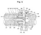
- FIG. 5is a longitudinal cross-sectional view of a portion of the inter-axle differential in accordance with the second embodiment of the present invention.
- the housing 4is ordinarily provided with a supply of lubricant, such as lubrication oil, therein.
- the inter-axle differential assembly 10in accordance with the first embodiment of the present invention, illustrated in detail in FIG. 2 , comprises an input shaft 14 rotatably supported in a bearing assembly indicated generally at 16 , a differential spider 32 drivingly coupled to the input shaft 14 and provided with a plurality of pinion gears 34 rotatably mounted thereon, a first side gear 20 and a second side gear 44 meshing with the pinion gears 34 , an output shaft 30 drivingly connected to the first side gear 20 , and a dedicated lubrication pump 50 disposed between the input shaft 14 and the output shaft 30 and solely for the purpose of lubricating components of the inter-axle differential assembly 10 during the differential action between the input shaft 14 and the output shaft 30 .
- the input shaft 14rotatably supported in a bearing assembly indicated generally at 16 , and has a yoke 18 attached thereto, which is adapted for receiving torque from a vehicle driveline (not shown).
- the differential spider 32drivingly engages the input shaft 14 by any appropriate means, preferably through a spline connection 36 .
- input torqueis transmitted directly to the differential spider 32 .
- the number of the pinion gears 34will be four, but the number can be as low as two and can be higher than four, although most practical applications would probably not contain more than six pinion gears.
- the first side gear 20is journalled in a second bearing assembly indicated generally at 22 , and has a reduced diameter pilot portion 24 of the input shaft 14 journalled therein.
- the first side gear 20includes a flange portion 26 integrally formed with a sleeve portion 28 .
- the flange portion 26is provided with a plurality of side gear teeth 27 formed thereon for meshing with the pinion gears 34 .
- the sleeve portion 28 of the first side gear 20is drivingly coupled with the output shaft 30 .
- An outboard end of the output shaft 30is adapted for connection to the rear drive axle (not shown) of the motor vehicle.
- the second side gear 44is rotatably mounted to the input shaft 14 by a sleeve bearing or bushing 48 for free rotation thereon. It will be appreciated that any other appropriate type of bearings, such as needle bearings, are also applicable.
- the second side gear 44has a plurality of gear teeth 46 thereon engaging the pinion gears 34 .
- a lubrication pump 50in accordance with the first embodiment of the present invention, is disposed between the input shaft 14 and the output shaft 30 of the inter-axle differential 10 within the sleeve portion 28 of the first side gear 20 .
- the lubrication pump 50is a gerotor pump.
- the reversible unidirectional flow gerotor pump 50comprises a rotor 52 having a plurality of external teeth, an impeller 54 having a plurality of internal teeth which are in meshing engagement with external teeth of the rotor 52 , and a pump body 56 housing the rotor 52 and the impeller 54 .
- the rotor 52is eccentrically arranged relative to the impeller 54 and is drivingly connected to the input shaft 14 through a rotor shaft 58 , as seen in FIG. 2 .
- the rotor 52has one less tooth than the impeller 54 , such that driving of the rotor 52 will in turn cause driving of the impeller 54 .
- the pump body 56is secured to the side gear 20 within its sleeve portion 28 by means of a pin 64 received in an arcuate groove 65 formed in the pump body 56 .
- An inlet port 60 and an outlet port 62are formed in the pump body 56 .
- Relative rotation of the rotor 52 to the impeller 54thus provides a series of variable volume chambers within pump 50 , resulting in the build up of fluid pressure and pumping of lubricant in response to relative rotation of the rotor 52 and impeller 54 , and thus in response to differential rotation between the input shaft 14 and the first side gear 20 .
- volumetric flow of lubricant produced by the lubrication pumpvaries in direct proportion to the differential rotational speed of the input and output shafts.
- the pump body 56is housed within the sleeve portion 28 of the first side gear 20 and located angularly by the pin 64 in the arcuate groove 65 formed in an outer peripheral surface of the pump body 56 .
- the groove 65extends angularly around 90° of the outer peripheral surface of the pump body 56 .
- the pump body 56is allowed to rotate 90° relative to the first side gear 20 depending on a relative direction of rotation of the rotor 52 with respect to the first side gear 20 .
- the pump body 56exchanges positions of the inlet port 60 and the outlet port 62 relative to the first side gear 20 in order to provide a reversible pumping function.
- the switching of ports 60 and 62allows the pump 50 to provide a unidirectional flow of lubricant regardless of the direction of the rotation of the rotor 52 .
- the lubricant under pressureflows from the outlet port of the lubrication pump 50 (the second port 62 in FIG. 3 ) through a gallery of fluid passages including a passage 70 provided in the input shaft 14 to lubricate the components of the inter-axle differential 10 via a number of cross passages, such as a cross passage 72 for lubricating the sleeve bearing 48 .
- the inter-axle differential assembly 10may have supplemental lubricant delivery means, such as a splash diversion and delivery channels (not shown).
- the inlet port 60 of the pump 50is in fluid communication with an inlet passage 76 provided in a differential support carrier 75 , trough an inlet cross passage 78 in the sleeve portion 28 of the first side gear 20 between seal rings 80 .
- pair of annular lip seals 80 ′may be used to seal the inlet passage 76 .
- the inlet passage 76is in turn fluidly connected to the supply of lubricant disposed in the housing 4 of the tandem axle power divider 2 , and may be fitted with a check valve (not shown) or an elevated oil reservoir (not shown) to aid in pump priming.
- FIG. 4illustrates an alternative embodiment of the reversible gerotor lubrication pump used in the inter-axle differential assembly 10 in accordance with the first embodiment of the present invention.
- An inboard end 15 of the input shaft 14is rotatably supported in the sleeve portion 28 of the first side gear 20 .
- a dedicated lubrication pump 150preferably a conventional gerotor pump of reversible unidirectional flow type, is disposed within the sleeve portion 28 of the first side gear 20 adjacent to the inboard end 15 of the input shaft 14 .
- the lubrication gerotor pump 150comprises a rotor 152 , an impeller 154 , and a port plate 157 having a first port 160 and a second port 162 .
- the rotor 152is drivingly connected to the input shaft 14 through a rotor shaft 158 .
- An outlet passage 163is formed within the tubular rotor shaft 158 .
- the lubricant under pressureflows from the outlet port 162 of the lubrication pump 150 through the passage 170 drilled in the input shaft 14 to lubricate the components of the inter-axle differential 10 via a number of cross passages, such as cross passages 72 .
- the port plate 157is located angularly by a pin 164 in an arcuate groove 165 formed on an outer peripheral surface of the port plate 157 .
- the groove 165is angularly extended around an outer peripheral surface of the port plate 157 to approximately 180°. Consequently, the port plate 157 is allowed to rotate 180° relative to the first side gear 20 depending on a relative direction of rotation of the pump rotor 152 with respect to the first side gear 20 . In this way, the port plate 157 exchanges positions of the inlet port 160 and the outlet port 162 relative to the first side gear 20 in order to provide a reversible pumping function.
- the switching of the ports 160 and 162allows the pump 150 to provide a unidirectional flow of lubricant regardless of the direction of the rotation of the rotor 152 .
- the inlet port 160 of the pump 150is in fluid communication with the inlet passage 76 provided in the differential support carrier 75 , trough an inlet cross passage 78 in the sleeve portion 28 of the first side gear 20 between seal rings 80 .
- pair of annular lip seals 80 ′may be used to seal the inlet passage 76 .
- any other appropriate sealing device for sealing the inlet passage 76is within the scope of the present invention.
- the inlet passage 76is fluidly connected to the supply of lubricant disposed in the housing 4 of the tandem axle power divider 2 , and may be fitted with a check valve (not shown) or an elevated oil reservoir (not shown) to aid in pump priming.
- an inboard end 215 of an input shaft 214is rotatably supported in a tubular inboard end 231 of an output shaft 230 .
- a dedicated lubrication pump 250preferably of conventional reversible unidirectional gerotor type, is disposed within the tubular inboard end 231 of the output shaft 230 adjacent to the inboard end 215 of the input shaft 214 .
- the lubrication gerotor pump 250comprises a rotor 252 , an impeller 254 , and a port plate 257 having an inlet port 260 .
- the rotor 252is drivingly connected to the input shaft 214 through a rotor shaft 258 .
- An outlet port 262is provided as a passage within the tubular rotor shaft 258 .
- the lubricant under pressureflows from the outlet port 262 of the lubrication pump 250 through a passage 270 drilled in the input shaft 214 to lubricate the components of the inter-axle differential 10 via a number of cross passages, such as cross passages 272 .
- the inlet port 260 of the pump 250is in fluid communication with an inlet passage 276 provided in a differential support carrier 275 , trough an inlet cross passage 178 in the tubular inboard end 231 of the output shaft 230 between seal rings 280 .
- pair of annular lip seals 280 ′may be used to seal the inlet passage 276 .
- any other appropriate sealing device for sealing the inlet passage 276is within the scope of the present invention.
- the inlet passage 276is fluidly connected to the supply of lubricant disposed in the housing 4 of the tandem axle power divider 2 , and may be fitted with a check valve (not shown) or an elevated oil reservoir (not shown) to aid in pump priming.
- a novel arrangement of the inter-axle differential assembly in accordance with the present invention including the dedicated lubrication pumpprovides a compact, efficient and low-cost solution for lubricating components of the inter-axle differential assembly only when needed.
- the present arrangement of the inter-axle differential assemblysubstantially reduces parasitic losses associated with powering lubrication pumps.
Landscapes
- Engineering & Computer Science (AREA)
- General Engineering & Computer Science (AREA)
- Mechanical Engineering (AREA)
- General Details Of Gearings (AREA)
- Rotary Pumps (AREA)
- Details And Applications Of Rotary Liquid Pumps (AREA)
Abstract
Description
Claims (3)
Priority Applications (9)
| Application Number | Priority Date | Filing Date | Title |
|---|---|---|---|
| US09/761,724US6855083B1 (en) | 2001-01-18 | 2001-01-18 | Lubrication pump for inter-axle differential |
| CA002427642ACA2427642A1 (en) | 2001-01-18 | 2001-12-27 | Lubication pump for inter-axle differential |
| CNB018221416ACN1263971C (en) | 2001-01-18 | 2001-12-27 | Lubrication pump for inter-axle differential |
| PCT/US2001/050061WO2002057657A1 (en) | 2001-01-18 | 2001-12-27 | Lubication pump for inter-axle differential |
| MXPA03004302AMXPA03004302A (en) | 2001-01-18 | 2001-12-27 | Lubication pump for inter-axle differential. |
| EP01987482AEP1352184A1 (en) | 2001-01-18 | 2001-12-27 | Lubication pump for inter-axle differential |
| BRPI0116769-3ABR0116769A (en) | 2001-01-18 | 2001-12-27 | wheelbase differential set |
| US10/186,926US6702703B2 (en) | 2001-01-18 | 2002-07-01 | Lubrication pump for inter-axle differential |
| US10/935,308US6997841B2 (en) | 2001-01-18 | 2004-09-08 | Lubrication pump for inter-axle differential |
Applications Claiming Priority (1)
| Application Number | Priority Date | Filing Date | Title |
|---|---|---|---|
| US09/761,724US6855083B1 (en) | 2001-01-18 | 2001-01-18 | Lubrication pump for inter-axle differential |
Related Child Applications (2)
| Application Number | Title | Priority Date | Filing Date |
|---|---|---|---|
| US10/186,926Continuation-In-PartUS6702703B2 (en) | 2001-01-18 | 2002-07-01 | Lubrication pump for inter-axle differential |
| US10/935,308ContinuationUS6997841B2 (en) | 2001-01-18 | 2004-09-08 | Lubrication pump for inter-axle differential |
Publications (1)
| Publication Number | Publication Date |
|---|---|
| US6855083B1true US6855083B1 (en) | 2005-02-15 |
Family
ID=25063084
Family Applications (2)
| Application Number | Title | Priority Date | Filing Date |
|---|---|---|---|
| US09/761,724Expired - LifetimeUS6855083B1 (en) | 2001-01-18 | 2001-01-18 | Lubrication pump for inter-axle differential |
| US10/935,308Expired - LifetimeUS6997841B2 (en) | 2001-01-18 | 2004-09-08 | Lubrication pump for inter-axle differential |
Family Applications After (1)
| Application Number | Title | Priority Date | Filing Date |
|---|---|---|---|
| US10/935,308Expired - LifetimeUS6997841B2 (en) | 2001-01-18 | 2004-09-08 | Lubrication pump for inter-axle differential |
Country Status (7)
| Country | Link |
|---|---|
| US (2) | US6855083B1 (en) |
| EP (1) | EP1352184A1 (en) |
| CN (1) | CN1263971C (en) |
| BR (1) | BR0116769A (en) |
| CA (1) | CA2427642A1 (en) |
| MX (1) | MXPA03004302A (en) |
| WO (1) | WO2002057657A1 (en) |
Cited By (6)
| Publication number | Priority date | Publication date | Assignee | Title |
|---|---|---|---|---|
| US20060207370A1 (en)* | 2003-05-28 | 2006-09-21 | Volvo Lastvagnar Ab | Device for lubrication of a gear |
| US20100105513A1 (en)* | 2008-10-23 | 2010-04-29 | Hilker Gregory J | Differential lubrication feed system in a drive axle assembly |
| US9291257B2 (en) | 2012-05-31 | 2016-03-22 | Dana Heavy Vehicle Systems Group, Llc | Power distribution unit with a forced lubrication flow assembly |
| US11156281B2 (en) | 2019-02-01 | 2021-10-26 | Dana Heavy Vehicle Systems Group, Llc | Axle assembly with lubrication pump |
| WO2023008195A1 (en)* | 2021-07-26 | 2023-02-02 | 株式会社アイシン | Vehicular driving device |
| US11808342B2 (en) | 2022-02-08 | 2023-11-07 | Dana Automotive Systems Group, Llc | Differential carrier |
Families Citing this family (17)
| Publication number | Priority date | Publication date | Assignee | Title |
|---|---|---|---|---|
| US6702703B2 (en)* | 2001-01-18 | 2004-03-09 | Dana Corporation | Lubrication pump for inter-axle differential |
| US7866444B2 (en)* | 2006-04-06 | 2011-01-11 | Fairfield Manufacturing Company, Inc. | Cascading oil flow bearing lubrication device |
| US7954574B2 (en)* | 2007-03-23 | 2011-06-07 | Fairfield Manufacturing Company, Inc. | Offset drive system for utility vehicles |
| US8056662B2 (en)* | 2007-03-23 | 2011-11-15 | Fairfield Manufacturing Company, Inc. | Lubrication system for right-angle drives used with utility vehicles |
| DE102007036554B4 (en)* | 2007-07-25 | 2009-06-25 | Getrag Getriebe- Und Zahnradfabrik Hermann Hagenmeyer Gmbh & Cie Kg | Lid-bearing assembly and method for mounting an actuator shaft |
| US8133143B2 (en)* | 2008-06-16 | 2012-03-13 | Fairfield Manufacturing Company, Inc. | Gear reducer electric motor assembly with internal brake |
| US8323143B2 (en) | 2009-12-02 | 2012-12-04 | Fairfield Manufacturing Company, Inc. | Integrated spindle-carrier electric wheel drive |
| FR2956460B1 (en)* | 2010-02-17 | 2012-05-25 | Peugeot Citroen Automobiles Sa | TRANSMISSION DEVICE EQUIPPED WITH A LUBRICATION FLUID PUMP. |
| US9103433B2 (en)* | 2013-02-26 | 2015-08-11 | Arvinmeritor Technology, Llc | Axle assembly and method of lubrication control |
| US10458517B2 (en) | 2015-05-22 | 2019-10-29 | Dana Heavy Vehicle Systems Group, Llc | Internal lube tank lube level control system |
| WO2017217570A1 (en)* | 2016-06-16 | 2017-12-21 | 주식회사 아너스 | Rotary-type mop cleaner having improved durability of gear drive unit |
| SE541530C2 (en)* | 2017-11-21 | 2019-10-29 | Scania Cv Ab | Axle Assembly and Vehicle |
| US11146157B2 (en)* | 2018-05-03 | 2021-10-12 | Schaeffler Technologies AG & Co. KG | Dual rotor electric machine in an automotive application |
| JP7070174B2 (en)* | 2018-07-06 | 2022-05-18 | トヨタ自動車株式会社 | Vehicle power transmission device |
| CN112112947B (en)* | 2020-10-20 | 2024-02-23 | 贵州群建精密机械有限公司 | Multi-input high-bearing-capacity vertical transmission device and lubricating method thereof |
| US11440348B1 (en)* | 2021-06-09 | 2022-09-13 | Arvinmeritor Technology, Llc | Axle assembly having a lubricant reservoir |
| CN113819227A (en)* | 2021-09-26 | 2021-12-21 | 一汽解放汽车有限公司 | Middle axle speed reducer assembly |
Citations (15)
| Publication number | Priority date | Publication date | Assignee | Title |
|---|---|---|---|---|
| US2861477A (en) | 1955-11-21 | 1958-11-25 | Mueller Otto | Pump and lock for differential |
| US3040600A (en) | 1955-11-21 | 1962-06-26 | Mueller Otto | Pump and lock for differential |
| US3393583A (en) | 1967-02-13 | 1968-07-23 | Mueller Otto | Self-locking differential transmission |
| US3550724A (en) | 1968-12-02 | 1970-12-29 | Eaton Yale & Towne | Pressure lubrication system for geared drive mechanism |
| US3590954A (en) | 1969-12-05 | 1971-07-06 | White Motor Corp | Differential mechanism |
| US3762503A (en) | 1971-04-14 | 1973-10-02 | Eaton Yale & Towne | Lubrication system for limited slip differential |
| US4733578A (en) | 1986-12-31 | 1988-03-29 | Dana Corporation | Bevel gear differential with conical spherical gear seats |
| US5302158A (en) | 1992-11-24 | 1994-04-12 | Eaton Corporation | Lubricant pumping in tandem drive axles |
| JPH06193713A (en)* | 1992-11-06 | 1994-07-15 | Hino Motors Ltd | Lubrication device of tandem type drive shaft |
| JPH06193712A (en)* | 1992-11-06 | 1994-07-15 | Hino Motors Ltd | Lubrication device of tandem type drive shaft |
| US5702319A (en) | 1995-10-13 | 1997-12-30 | Dana Corporation | Hydromechanical system for limiting differential speed between differentially rotating members |
| US5709627A (en) | 1995-03-28 | 1998-01-20 | Tochigi Fuji Sangyo Kabushiki Kaisha | Differential unit with means for mixing air into the hydraulic actuator |
| US5711408A (en)* | 1996-05-09 | 1998-01-27 | Dana Corporation | Reversible gerotor pump |
| US5916052A (en)* | 1995-04-28 | 1999-06-29 | Dana Corporation | Hydromechanical system for limiting differential speed between differentially rotating members |
| US5964584A (en) | 1992-09-02 | 1999-10-12 | Lorentz; Bernt | Vane pump having a shaftless balanced rotor |
Family Cites Families (4)
| Publication number | Priority date | Publication date | Assignee | Title |
|---|---|---|---|---|
| US3994634A (en)* | 1975-10-28 | 1976-11-30 | Rockwell International Corporation | Reversible lubricant pump |
| US5007806A (en)* | 1989-03-30 | 1991-04-16 | Mallory, Inc. | Fuel pump |
| US6702703B2 (en)* | 2001-01-18 | 2004-03-09 | Dana Corporation | Lubrication pump for inter-axle differential |
| US7258644B2 (en)* | 2003-06-30 | 2007-08-21 | Dana Corporation | Tandem axle carrier structural rib |
- 2001
- 2001-01-18USUS09/761,724patent/US6855083B1/ennot_activeExpired - Lifetime
- 2001-12-27WOPCT/US2001/050061patent/WO2002057657A1/ennot_activeApplication Discontinuation
- 2001-12-27MXMXPA03004302Apatent/MXPA03004302A/enactiveIP Right Grant
- 2001-12-27CACA002427642Apatent/CA2427642A1/ennot_activeAbandoned
- 2001-12-27CNCNB018221416Apatent/CN1263971C/ennot_activeExpired - Fee Related
- 2001-12-27BRBRPI0116769-3Apatent/BR0116769A/ennot_activeIP Right Cessation
- 2001-12-27EPEP01987482Apatent/EP1352184A1/ennot_activeWithdrawn
- 2004
- 2004-09-08USUS10/935,308patent/US6997841B2/ennot_activeExpired - Lifetime
Patent Citations (16)
| Publication number | Priority date | Publication date | Assignee | Title |
|---|---|---|---|---|
| US3040600A (en) | 1955-11-21 | 1962-06-26 | Mueller Otto | Pump and lock for differential |
| US2861477A (en) | 1955-11-21 | 1958-11-25 | Mueller Otto | Pump and lock for differential |
| US3393583A (en) | 1967-02-13 | 1968-07-23 | Mueller Otto | Self-locking differential transmission |
| US3550724A (en) | 1968-12-02 | 1970-12-29 | Eaton Yale & Towne | Pressure lubrication system for geared drive mechanism |
| US3590954A (en) | 1969-12-05 | 1971-07-06 | White Motor Corp | Differential mechanism |
| US3762503A (en) | 1971-04-14 | 1973-10-02 | Eaton Yale & Towne | Lubrication system for limited slip differential |
| US4733578A (en) | 1986-12-31 | 1988-03-29 | Dana Corporation | Bevel gear differential with conical spherical gear seats |
| US5964584A (en) | 1992-09-02 | 1999-10-12 | Lorentz; Bernt | Vane pump having a shaftless balanced rotor |
| JPH06193712A (en)* | 1992-11-06 | 1994-07-15 | Hino Motors Ltd | Lubrication device of tandem type drive shaft |
| JPH06193713A (en)* | 1992-11-06 | 1994-07-15 | Hino Motors Ltd | Lubrication device of tandem type drive shaft |
| EP0599050A1 (en) | 1992-11-24 | 1994-06-01 | Eaton Corporation | Lubricant pumping in tandem drive axles |
| US5302158A (en) | 1992-11-24 | 1994-04-12 | Eaton Corporation | Lubricant pumping in tandem drive axles |
| US5709627A (en) | 1995-03-28 | 1998-01-20 | Tochigi Fuji Sangyo Kabushiki Kaisha | Differential unit with means for mixing air into the hydraulic actuator |
| US5916052A (en)* | 1995-04-28 | 1999-06-29 | Dana Corporation | Hydromechanical system for limiting differential speed between differentially rotating members |
| US5702319A (en) | 1995-10-13 | 1997-12-30 | Dana Corporation | Hydromechanical system for limiting differential speed between differentially rotating members |
| US5711408A (en)* | 1996-05-09 | 1998-01-27 | Dana Corporation | Reversible gerotor pump |
Non-Patent Citations (1)
| Title |
|---|
| Parker, P., ed. Mcgraw-Hill Dictionary of Scientific and Technical Terms, 5<th >ed. New York, McGraw-Hill, 1994. p. 997.* |
Cited By (10)
| Publication number | Priority date | Publication date | Assignee | Title |
|---|---|---|---|---|
| US20060207370A1 (en)* | 2003-05-28 | 2006-09-21 | Volvo Lastvagnar Ab | Device for lubrication of a gear |
| US7220208B2 (en)* | 2003-05-28 | 2007-05-22 | Volvo Lastvagnar Ab | Device for lubrication of a gear |
| US20100105513A1 (en)* | 2008-10-23 | 2010-04-29 | Hilker Gregory J | Differential lubrication feed system in a drive axle assembly |
| US8409044B2 (en) | 2008-10-23 | 2013-04-02 | American Axle & Manufacturing, Inc. | Differential lubrication feed system in a drive axle assembly |
| US8512193B1 (en) | 2008-10-23 | 2013-08-20 | American Axle & Manufacturing, Inc. | Differential lubrication feed system in a drive axle assembly |
| US9291257B2 (en) | 2012-05-31 | 2016-03-22 | Dana Heavy Vehicle Systems Group, Llc | Power distribution unit with a forced lubrication flow assembly |
| US11156281B2 (en) | 2019-02-01 | 2021-10-26 | Dana Heavy Vehicle Systems Group, Llc | Axle assembly with lubrication pump |
| WO2023008195A1 (en)* | 2021-07-26 | 2023-02-02 | 株式会社アイシン | Vehicular driving device |
| EP4379239A4 (en)* | 2021-07-26 | 2024-11-27 | Aisin Corporation | VEHICLE DRIVE DEVICE |
| US11808342B2 (en) | 2022-02-08 | 2023-11-07 | Dana Automotive Systems Group, Llc | Differential carrier |
Also Published As
| Publication number | Publication date |
|---|---|
| US20050032602A1 (en) | 2005-02-10 |
| US6997841B2 (en) | 2006-02-14 |
| BR0116769A (en) | 2006-05-09 |
| WO2002057657A1 (en) | 2002-07-25 |
| CA2427642A1 (en) | 2002-07-25 |
| CN1486404A (en) | 2004-03-31 |
| EP1352184A1 (en) | 2003-10-15 |
| MXPA03004302A (en) | 2003-08-19 |
| CN1263971C (en) | 2006-07-12 |
Similar Documents
| Publication | Publication Date | Title |
|---|---|---|
| US6855083B1 (en) | Lubrication pump for inter-axle differential | |
| EP1378687B1 (en) | Lubrication pump for inter-axle differential | |
| US4489626A (en) | Lubrication system for a planetary gear system | |
| US5302158A (en) | Lubricant pumping in tandem drive axles | |
| JP2950100B2 (en) | Powertrain lubrication system for electric vehicles | |
| CN102297130B (en) | High efficiency fixed displacement vane pump | |
| US7958969B2 (en) | Transfer device for vehicle | |
| US11906024B2 (en) | Vehicle drive device | |
| US6991574B2 (en) | Dual level oil impeller for drive axle assembly | |
| US9593762B2 (en) | Drive axle with pump managed oil flow | |
| US10955043B2 (en) | Axle assembly with variable speed pump | |
| CN107131291B (en) | Vacuum driving hydraulic balance system | |
| JP2017133564A (en) | Vehicular motor drive device | |
| JP3771956B2 (en) | Power transmission device | |
| US10767754B2 (en) | Driveline component with differential assembly and differential lubrication device | |
| JP2864444B2 (en) | Lubricating device for tandem drive shaft | |
| JPH06219174A (en) | Transfer device | |
| JPH0236736Y2 (en) | ||
| JPH08135771A (en) | Lubricating device for inter-axle differential | |
| JPH0262462A (en) | Lubrication oil introduction device for transfer | |
| US20200309249A1 (en) | Axle assembly with lubrication pump | |
| JPH09144841A (en) | Differential device | |
| JPS646337Y2 (en) | ||
| JPH0440977Y2 (en) | ||
| JPS60230583A (en) | Gear body type differential pump |
Legal Events
| Date | Code | Title | Description |
|---|---|---|---|
| AS | Assignment | Owner name:DANA CORPORATION, OHIO Free format text:ASSIGNMENT OF ASSIGNORS INTEREST;ASSIGNORS:WAGLE, LAWRENCE;KWASNIEWSKI, DALE;ZIECH, JAMES F.;REEL/FRAME:011478/0786 Effective date:20010117 | |
| STCF | Information on status: patent grant | Free format text:PATENTED CASE | |
| FEPP | Fee payment procedure | Free format text:PAYOR NUMBER ASSIGNED (ORIGINAL EVENT CODE: ASPN); ENTITY STATUS OF PATENT OWNER: LARGE ENTITY | |
| AS | Assignment | Owner name:DANA HEAVY VEHICLE SYSTEMS GROUP, LLC, OHIO Free format text:ASSIGNMENT OF ASSIGNORS INTEREST;ASSIGNOR:DANA CORPORATION;REEL/FRAME:020571/0741 Effective date:20080131 Owner name:DANA HEAVY VEHICLE SYSTEMS GROUP, LLC,OHIO Free format text:ASSIGNMENT OF ASSIGNORS INTEREST;ASSIGNOR:DANA CORPORATION;REEL/FRAME:020571/0741 Effective date:20080131 | |
| AS | Assignment | Owner name:CITICORP USA, INC., NEW YORK Free format text:INTELLECTUAL PROPERTY TERM FACILITY SECURITY AGREEMENT;ASSIGNORS:DANA HOLDING CORPORATION;DANA LIMITED;DANA AUTOMOTIVE SYSTEMS GROUP, LLC;AND OTHERS;REEL/FRAME:020859/0359 Effective date:20080131 Owner name:CITICORP USA, INC., NEW YORK Free format text:INTELLECTUAL PROPERTY REVOLVING FACILITY SECURITY AGREEMENT;ASSIGNORS:DANA HOLDING CORPORATION;DANA LIMITED;DANA AUTOMOTIVE SYSTEMS GROUP, LLC;AND OTHERS;REEL/FRAME:020859/0249 Effective date:20080131 Owner name:CITICORP USA, INC.,NEW YORK Free format text:INTELLECTUAL PROPERTY REVOLVING FACILITY SECURITY AGREEMENT;ASSIGNORS:DANA HOLDING CORPORATION;DANA LIMITED;DANA AUTOMOTIVE SYSTEMS GROUP, LLC;AND OTHERS;REEL/FRAME:020859/0249 Effective date:20080131 Owner name:CITICORP USA, INC.,NEW YORK Free format text:INTELLECTUAL PROPERTY TERM FACILITY SECURITY AGREEMENT;ASSIGNORS:DANA HOLDING CORPORATION;DANA LIMITED;DANA AUTOMOTIVE SYSTEMS GROUP, LLC;AND OTHERS;REEL/FRAME:020859/0359 Effective date:20080131 | |
| FPAY | Fee payment | Year of fee payment:4 | |
| FEPP | Fee payment procedure | Free format text:PAYER NUMBER DE-ASSIGNED (ORIGINAL EVENT CODE: RMPN); ENTITY STATUS OF PATENT OWNER: LARGE ENTITY Free format text:PAYOR NUMBER ASSIGNED (ORIGINAL EVENT CODE: ASPN); ENTITY STATUS OF PATENT OWNER: LARGE ENTITY | |
| FPAY | Fee payment | Year of fee payment:8 | |
| FPAY | Fee payment | Year of fee payment:12 | |
| AS | Assignment | Owner name:CITIBANK, N.A., NEW YORK Free format text:SECURITY AGREEMENT SUPPLEMENT;ASSIGNORS:DANA HEAVY VEHICLE SYSTEMS GROUP, LLC;DANA LIMITED;DANA AUTOMOTIVE SYSTEMS GROUP, LLC;AND OTHERS;REEL/FRAME:052459/0224 Effective date:20200416 Owner name:CITIBANK, N.A., NEW YORK Free format text:SECURITY AGREEMENT (BRIDGE);ASSIGNORS:DANA HEAVY VEHICLE SYSTEMS GROUP, LLC;DANA LIMITED;DANA AUTOMOTIVE SYSTEMS GROUP, LLC;AND OTHERS;REEL/FRAME:052459/0001 Effective date:20200416 | |
| AS | Assignment | Owner name:DANA LIMITED, OHIO Free format text:RELEASE BY SECURED PARTY;ASSIGNOR:CITIBANK, N.A.;REEL/FRAME:053309/0686 Effective date:20200619 Owner name:DANA AUTOMOTIVE SYSTEMS GROUP, LLC, OHIO Free format text:RELEASE BY SECURED PARTY;ASSIGNOR:CITIBANK, N.A.;REEL/FRAME:053309/0686 Effective date:20200619 Owner name:DANA HEAVY VEHICLE SYSTEMS GROUP, LLC, OHIO Free format text:RELEASE BY SECURED PARTY;ASSIGNOR:CITIBANK, N.A.;REEL/FRAME:053309/0686 Effective date:20200619 Owner name:FAIRFIELD MANUFACTURING COMPANY, INC., OHIO Free format text:RELEASE BY SECURED PARTY;ASSIGNOR:CITIBANK, N.A.;REEL/FRAME:053309/0686 Effective date:20200619 |