US6854145B2 - Patient support - Google Patents
Patient supportDownload PDFInfo
- Publication number
- US6854145B2 US6854145B2US10/704,168US70416803AUS6854145B2US 6854145 B2US6854145 B2US 6854145B2US 70416803 AUS70416803 AUS 70416803AUS 6854145 B2US6854145 B2US 6854145B2
- Authority
- US
- United States
- Prior art keywords
- foot
- coupled
- arm
- patient support
- coupler
- Prior art date
- Legal status (The legal status is an assumption and is not a legal conclusion. Google has not performed a legal analysis and makes no representation as to the accuracy of the status listed.)
- Expired - Fee Related
Links
- 230000007246mechanismEffects0.000claimsdescription10
- 244000309466calfSpecies0.000description75
- 230000008878couplingEffects0.000description2
- 238000010168coupling processMethods0.000description2
- 238000005859coupling reactionMethods0.000description2
- 208000010496Heart ArrestDiseases0.000description1
- 230000008901benefitEffects0.000description1
- 230000003993interactionEffects0.000description1
- 230000004048modificationEffects0.000description1
- 238000012986modificationMethods0.000description1
- 230000000717retained effectEffects0.000description1
- 239000000126substanceSubstances0.000description1
Images


Classifications
- A—HUMAN NECESSITIES
- A61—MEDICAL OR VETERINARY SCIENCE; HYGIENE
- A61G—TRANSPORT, PERSONAL CONVEYANCES, OR ACCOMMODATION SPECIALLY ADAPTED FOR PATIENTS OR DISABLED PERSONS; OPERATING TABLES OR CHAIRS; CHAIRS FOR DENTISTRY; FUNERAL DEVICES
- A61G7/00—Beds specially adapted for nursing; Devices for lifting patients or disabled persons
- A61G7/05—Parts, details or accessories of beds
- A—HUMAN NECESSITIES
- A61—MEDICAL OR VETERINARY SCIENCE; HYGIENE
- A61G—TRANSPORT, PERSONAL CONVEYANCES, OR ACCOMMODATION SPECIALLY ADAPTED FOR PATIENTS OR DISABLED PERSONS; OPERATING TABLES OR CHAIRS; CHAIRS FOR DENTISTRY; FUNERAL DEVICES
- A61G13/00—Operating tables; Auxiliary appliances therefor
- A61G13/0009—Obstetrical tables or delivery beds
- A—HUMAN NECESSITIES
- A61—MEDICAL OR VETERINARY SCIENCE; HYGIENE
- A61G—TRANSPORT, PERSONAL CONVEYANCES, OR ACCOMMODATION SPECIALLY ADAPTED FOR PATIENTS OR DISABLED PERSONS; OPERATING TABLES OR CHAIRS; CHAIRS FOR DENTISTRY; FUNERAL DEVICES
- A61G13/00—Operating tables; Auxiliary appliances therefor
- A61G13/10—Parts, details or accessories
- A61G13/12—Rests specially adapted therefor; Arrangements of patient-supporting surfaces
- A—HUMAN NECESSITIES
- A61—MEDICAL OR VETERINARY SCIENCE; HYGIENE
- A61G—TRANSPORT, PERSONAL CONVEYANCES, OR ACCOMMODATION SPECIALLY ADAPTED FOR PATIENTS OR DISABLED PERSONS; OPERATING TABLES OR CHAIRS; CHAIRS FOR DENTISTRY; FUNERAL DEVICES
- A61G13/00—Operating tables; Auxiliary appliances therefor
- A61G13/10—Parts, details or accessories
- A61G13/101—Clamping means for connecting accessories to the operating table
- A—HUMAN NECESSITIES
- A61—MEDICAL OR VETERINARY SCIENCE; HYGIENE
- A61G—TRANSPORT, PERSONAL CONVEYANCES, OR ACCOMMODATION SPECIALLY ADAPTED FOR PATIENTS OR DISABLED PERSONS; OPERATING TABLES OR CHAIRS; CHAIRS FOR DENTISTRY; FUNERAL DEVICES
- A61G13/00—Operating tables; Auxiliary appliances therefor
- A61G13/10—Parts, details or accessories
- A61G13/12—Rests specially adapted therefor; Arrangements of patient-supporting surfaces
- A61G13/1205—Rests specially adapted therefor; Arrangements of patient-supporting surfaces for specific parts of the body
- A61G13/121—Head or neck
- A—HUMAN NECESSITIES
- A61—MEDICAL OR VETERINARY SCIENCE; HYGIENE
- A61G—TRANSPORT, PERSONAL CONVEYANCES, OR ACCOMMODATION SPECIALLY ADAPTED FOR PATIENTS OR DISABLED PERSONS; OPERATING TABLES OR CHAIRS; CHAIRS FOR DENTISTRY; FUNERAL DEVICES
- A61G13/00—Operating tables; Auxiliary appliances therefor
- A61G13/10—Parts, details or accessories
- A61G13/12—Rests specially adapted therefor; Arrangements of patient-supporting surfaces
- A61G13/1205—Rests specially adapted therefor; Arrangements of patient-supporting surfaces for specific parts of the body
- A61G13/1245—Knees, upper or lower legs
- A—HUMAN NECESSITIES
- A61—MEDICAL OR VETERINARY SCIENCE; HYGIENE
- A61G—TRANSPORT, PERSONAL CONVEYANCES, OR ACCOMMODATION SPECIALLY ADAPTED FOR PATIENTS OR DISABLED PERSONS; OPERATING TABLES OR CHAIRS; CHAIRS FOR DENTISTRY; FUNERAL DEVICES
- A61G13/00—Operating tables; Auxiliary appliances therefor
- A61G13/10—Parts, details or accessories
- A61G13/12—Rests specially adapted therefor; Arrangements of patient-supporting surfaces
- A61G13/1205—Rests specially adapted therefor; Arrangements of patient-supporting surfaces for specific parts of the body
- A61G13/125—Ankles or feet
- A—HUMAN NECESSITIES
- A61—MEDICAL OR VETERINARY SCIENCE; HYGIENE
- A61G—TRANSPORT, PERSONAL CONVEYANCES, OR ACCOMMODATION SPECIALLY ADAPTED FOR PATIENTS OR DISABLED PERSONS; OPERATING TABLES OR CHAIRS; CHAIRS FOR DENTISTRY; FUNERAL DEVICES
- A61G13/00—Operating tables; Auxiliary appliances therefor
- A61G13/10—Parts, details or accessories
- A61G13/12—Rests specially adapted therefor; Arrangements of patient-supporting surfaces
- A61G13/128—Rests specially adapted therefor; Arrangements of patient-supporting surfaces with mechanical surface adaptations
- A61G13/1285—Rests specially adapted therefor; Arrangements of patient-supporting surfaces with mechanical surface adaptations having modular surface parts, e.g. being replaceable or turnable
- Y—GENERAL TAGGING OF NEW TECHNOLOGICAL DEVELOPMENTS; GENERAL TAGGING OF CROSS-SECTIONAL TECHNOLOGIES SPANNING OVER SEVERAL SECTIONS OF THE IPC; TECHNICAL SUBJECTS COVERED BY FORMER USPC CROSS-REFERENCE ART COLLECTIONS [XRACs] AND DIGESTS
- Y10—TECHNICAL SUBJECTS COVERED BY FORMER USPC
- Y10S—TECHNICAL SUBJECTS COVERED BY FORMER USPC CROSS-REFERENCE ART COLLECTIONS [XRACs] AND DIGESTS
- Y10S5/00—Beds
- Y10S5/905—Beds with light emitting means
Definitions
- the present inventionrelates to patient supports such as hospital beds, carts, chairs, and stretchers. More particularly, the present invention relates to a light assembly releasably coupled to a patient support.
- a patient supportcomprises a patient support surface facing upwardly toward a patient, and a storage surface positioned in spaced relation to the patient support surface. At least one retainer is coupled to the storage surface.
- a light sourceis configured to be moved between a use position and a storage position, wherein the light source is configured to provide light for a caregiver when in the use position, and the light source is releasably supported by the retainer when in the storage position.
- the light sourceis configured to direct light toward a patient supported on the patient support surface when in the use position, while the light source is configured to be positioned in spaced relation to the patient support surface when in the storage position.
- a coupleris configured to releasably support the light source when in the use position.
- an armis coupled to the light source, and the retainer includes a resilient clip configured to releasably couple to the arm.
- the patient supportincludes a head portion and a foot portion spaced apart from the head portion, and the patient support surface and the storage surface are defined by the foot portion.
- the foot portionillustratively includes a pair of laterally spaced apart foot supports defining an access opening therebetween, and the coupler is coupled to at least one of the foot supports such that the light source is supported by at least one of the foot supports when in the use position.
- the foot portionincludes a removable foot section, and the at least one retainer is supported by the removable foot section.
- a bedcomprises a frame, and a head portion supported by the frame.
- a foot portionis supported by the frame and is spaced apart from the head portion.
- a seat portionis supported by the frame and is positioned intermediate the head portion and the foot portion.
- the foot portionincludes a foot section removably supported by the frame, the foot section including an underside and a storage area positioned on the underside.
- a light assemblyis configured to be removably coupled to the foot section within the storage area.
- the light assemblyincludes a light source and an arm coupled to the light source.
- the foot sectionincludes a retainer configure to removably couple the arm to the foot section.
- a coupleris supported by the foot portion, and the arm of the light assembly is configured to be releasably coupled to the coupler.
- the foot portionillustratively includes a pair of laterally spaced foot supports configured for movement relative to the frame, and the coupler is coupled to at least one of the foot supports.
- a bedcomprises a frame and a patient support portion supported by the frame.
- the patient support portionincludes an upwardly facing patient support surface and a downwardly facing storage surface.
- a retaineris coupled to the storage surface, and a light assembly is configured to be releasably coupled to the retainer.
- the patient support portionincludes a section removably coupled to the frame.
- the light assemblyincludes a light source and an arm coupled to the light source.
- the retaineris configured to removably couple the arm to the patient support portion.
- FIG. 1is a perspective view of a patient support having a head section, a seat section, a foot section, and two foot supports positioned under the foot section;
- FIG. 2is a perspective view similar to FIG. 1 showing the foot section removed to expose the foot supports and that the foot supports are movable;
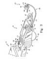
- FIG. 3is a perspective view of one of the foot supports showing a light source coupled to the foot support;
- FIG. 4is a bottom plan view of the foot support of FIG. 3 , with a housing of the foot support removed for clarity, showing a position adjustment mechanism of the foot support;
- FIG. 5is a bottom plan view similar to FIG. 4 showing the foot support being movable between first (phantom lines) and second (solid lines) rotational positions;
- FIG. 6is a side elevation view of the foot support showing the foot support in a substantially horizontal position
- FIG. 7is a side elevation view similar to FIG. 6 showing a portion of the foot support being movable between substantially horizontal (phantom lines) and raised (solid lines) positions;
- FIG. 8is an exploded perspective view of a portion of the foot support and a portion of the light source
- FIG. 9is a cross-sectional view taken along line 9 — 9 of FIG. 8 , illustrating the arm inserted into the bracket;
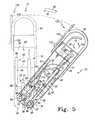
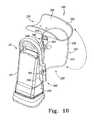
- FIG. 10is an elevation view of the light source coupled to a storage surface of the foot section of the bed
- FIG. 11is a perspective view of an alternative embodiment patient support having a head portion, a seat portion, and a foot portion, the foot portion including a foot section and two foot supports positioned under the foot section;
- FIG. 12is a perspective view similar to FIG. 11 showing the foot section removed to expose the foot supports and the patient support further including a calf support positioned under each foot support;
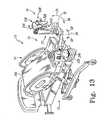
- FIG. 13is a perspective view similar to FIG. 12 showing each of the foot supports being rotated outwardly about a substantially vertical axis and upwardly about a substantially horizontal axis;
- FIG. 14is a perspective view of one of the calf supports of FIG. 13 showing the calf support including a foot support coupler, a calf holder, an arm extending from the foot support coupler toward the calf holder, and another coupler positioned between the arm and the calf holder and the arm and calf holder of the calf support being movable between a storage position (phantom lines) and a use position (solid lines);
- FIG. 15is an exploded perspective view of the foot support coupler and a portion of the arm of the calf support;
- FIG. 16is a perspective view similar to FIG. 14 showing the calf holder of the calf support being rotated from a storage position (phantom lines) to a use position (solid lines);
- FIG. 17is an elevational view, with portions cutaway, of the coupler and portions of the arm and calf holder showing the coupler coupling the arm to the calf holder;
- FIG. 18is a perspective view similar to FIG. 13 showing the calf supports in their use position
- FIG. 19is a perspective view, similar to FIG. 15 , of an alternative foot support coupler and a portion of the arm of the calf support;
- FIG. 20is a perspective view, with portions cutaway, of the patient support shown in FIG. 11 showing the patient support including a frame, a support surface, and a release system;
- FIG. 21is a perspective view of a portion of the release system of FIG. 20 ;
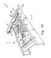
- FIG. 22is a perspective view, with portions cutaway, similar to FIG. 20 , showing the release system being actuated to lower the head portion of the support surface.
- the head portion 14is spaced apart from foot portion 18 by seat portion 16 .
- the portions 14 , 16 , 18may be articulated for movement relative to each other.
- the foot portion 18includes a foot section 20 and laterally spaced apart foot supports 22 , 24 , as shown in FIGS. 1 and 2 .
- the hospital bed 10is a birthing bed
- foot section 20is selectively removable from the remainder of hospital bed 10 to provide access to a patient on bed 10 as shown in FIG. 2 .
- the foot supports 22 , 24are positioned under or below foot section 20 as shown in FIG. 1 . Removal of the foot section 20 exposes the foot supports 22 , 24 as shown in FIG. 2 .
- the foot supports 22 , 24are movable about a substantially vertical axis 26 in directions 28 , 30 and a substantially horizontal axis 32 in directions 34 , 36 , as shown in FIG. 2 , so that the foot supports 22 , 24 may be placed in a desired position.
- Each foot support 22 , 24includes first and second frame sections 38 , 40 , a flexible housing section 42 extending between frame sections 38 , 40 , a foot panel 44 coupled to second frame section 40 , a handle 46 coupled to second frame section 40 , and position adjustment mechanism 48 .
- the foot panel 44is formed to include a recess 50 sized and shaped to receive a patient's foot.
- the position adjustment mechanism 48permits foot panel 44 to move relative to frame 12 about axes 26 , 32 in directions 28 , 30 , 34 , 36 so that the foot panel 44 may be positioned to receive a patient's foot in recess 50 .
- the position adjustment mechanism 48includes a handle 52 , first and second clutches 54 , 56 , first and second linkages 58 , 60 extending between handle 52 and first and second clutches 54 , 56 , respectively, and a spring 62 .
- the clutches 54 , 56may be positioned in an engaged position wherein relative movement of the foot panel 44 and frame 12 is not permitted and a disengaged position wherein relative movement is permitted. For example, when first clutch 54 is disengaged, the foot panel 44 is permitted to move relative to frame 12 about the vertical axis 26 , as shown in FIGS. 4 and 5 , and when the second clutch 56 is disengaged, foot panel 44 is permitted to move relative to the frame 12 about the horizontal axis 32 as shown in FIGS. 6 and 7 .
- the caregivermoves the handle 52 of position adjustment mechanism 48 in directions 64 , 66 about a pivot axis 68 .
- handle 52is coupled to the first and second linkages 58 , 60 which are coupled to the first and second clutches 54 , 56 , respectively.
- the clutches 54 , 56are normally in the engaged position and the handle 52 must be moved by the caregiver in direction 64 to disengage the clutches 54 , 56 .
- Moving the handle 52 in direction 64 about pivot axis 68moves the linkages 58 , 60 which in turn moves the clutches 54 , 56 from their engaged position to their disengaged position.
- the handle 52 of the position adjustment mechanism 48is positioned adjacent to handle 46 of foot support 22 , 24 so that a caregiver may simultaneously grab both handles 46 , 52 to disengage clutches 54 , 56 and move foot support 22 , 24 in directions 28 , 30 , 34 , 36 about axes 26 , 32 .
- Each of these clutches 54 , 56include a clamp 70 and a rod 72 that extends through clamp 70 as shown in FIG. 4 .
- the clamp 70is movable between an engaged position wherein the clamp 70 interacts with the rod 72 to prevent the rod 72 from moving through the clamp 70 and a disengaged position wherein the rod 72 is permitted to move through the clamp 70 .
- the rod 72is movable relative to the clamp 70 when the clamp 70 is in its disengaged position.
- the clamp 70 of first clutch 54is coupled to frame 12 and the rod 72 of first clutch 54 is coupled to the first frame section 38 of foot support 24 , 26 .
- the first frame section 38 of each foot support 24 , 26includes a rod support 74 and an end of the rod 72 of first clutch 54 is pivotally coupled to rod support 74 .
- the clamp 70 of first clutch 54is coupled to frame 12 by portions of foot support 22 , 24 that are fixed to frame 12 . These fixed portions of foot support 22 , 24 include a bushing 76 and a clamp support 78 coupled to bushing 76 .
- the frame 12 of bed 10includes a post 80 that extends vertically upward through an aperture 82 formed in bushing 76 as shown in FIGS. 1-5 .
- the foot support 22 , 24rotates about this post 80 and thus post 80 defines vertical axis 26 .
- the bushing 76includes a keyway or slot 84 and the post 80 includes a key 86 that is positioned in slot 84 to fix the rotational position of the bushing 76 and clamp support 78 relative to the frame 12 .
- the clamp 70is pivotally coupled to clamp support 78 to permit pivoting of the clamp 70 relative to frame 12 .
- the foot panel 44When the first clutch 54 is in the engaged position, the foot panel 44 is prevented from rotating in directions 28 , 30 about vertical axis 26 defined by post 80 . This rotation is prevented because the position of the rod 72 is fixed relative to the position of the clamp 70 .
- the first clutch 54To move the foot panel 44 about vertical axis 26 , the first clutch 54 is moved to its disengaged position so the rod 72 and thus all portions of foot support 22 , 24 other than bushing 76 and clamp support 78 are permitted to move relative to the clamp 70 and frame 12 .
- the rod 72travels through and relative to clamp 70 along an axial path.
- the clamp 70is rotatably coupled to clamp support 78 to pivot about a vertical axis 88 that is parallel to vertical axis 26 defined by post 80 .
- first clutch 54When the first clutch 54 is disengaged and the caregiver moves foot support 22 , 24 about vertical axis 26 in directions 28 , 30 , the clamp 70 rotates about this vertical axis 88 to permit the rod 72 to rotate and travel axially through clamp 70 .
- the second clutch 56is similarly movable between an engaged position and a disengaged position to prevent or permit, respectively, relative movement of the first and second frame sections 38 , 40 in directions 34 , 36 about horizontal axis 32 as shown in FIGS. 6 and 7 .
- the second clutch 56has its rod 72 coupled to the first frame section 38 and its clamp 70 coupled to the second frame section 40 .
- the first frame section 38includes a rod support 90 pivotally coupled to rod 72 of second clutch 56 and the second frame section 40 includes a clamp support 91 pivotally coupled to clamp 70 of second clutch 56 .
- a pivot pin 92pivotally couples an end of rod 72 to rod support 90 so that rod 72 may pivot about a pivot axis 94 defined by pivot pin 92 .
- the rod 72When the second clutch 56 is in its disengaged position, the rod 72 is movable through the clamp 70 to permit the second frame section 40 to rotate in directions 34 , 36 about horizontal axis 32 relative to first frame section 38 and when the clutch 56 is in its engaged position, this movement is not permitted.
- the rod 72travels axially through and relative to clamp 70 and pivots about a pivot axis 94 as the second frame section 40 is rotated about horizontal axis 32 .
- the first and second clutches 54 , 56are Mec-LokTM clutches available from P. L. Porter Controls, Inc. of Woodland Hills, Calif.
- other types of devicessuch as a key/slot device can be used to permit and prevent movement of the foot panel relative to the frame.
- the linkages 58 , 60are wires that transfer the rotational motion of handle 46 to clutches 54 , 56 .
- other types of linkagescan be used including gears, mechanical links, electrical line for electrical signals, fiber-optic line for optic signals, etc.
- the spring 62is configured to assist the caregiver in moving the second frame section 40 upwardly in direction 34 about horizontal axis 32 .
- the spring 62biases the second frame section 40 upwardly in direction 34 .
- This biasing force provided by the spring 62compensates for the weight of the second frame section 40 and any force or weight generated by a patient's foot positioned in foot support 22 , 24 .
- the caregiverlowers the foot support 22 , 24 in direction 36 , the caregiver must move the foot support 22 , 24 against the biasing force of the spring 62 .
- the caregiveris assisted in moving against the biasing force by the weight of the second frame section 40 and possibly a force and/or weight from a patient's foot.
- the spring 62is a gas spring having a cylinder 96 pivotally coupled to second frame section 40 and a piston 98 pivotally coupled to first frame section 38 as shown in FIGS. 4 and 5 .
- the gas spring 62is configured to bias piston 98 away from cylinder 96 in direction 110 to assist the caregiver in raising second frame section 40 as discussed above.
- other devicessuch as a coil spring can be used to assist a caregiver in raising the second frame section relative to the first frame section.
- the flexible housing section 42includes a bellows portion 112 extending between the first and second frame sections 38 , 40 and a cover portion 114 that covers the first frame section 38 .
- the flexible housing section 42expands and contracts to maintain a continuous housing for the clutches 54 , 56 , spring 62 , and linkages 58 , 60 .
- the flexible housing section 42cooperates with the first and second frame sections 38 , 40 to prevent or at least minimize substances from coming into contact with for the clutches 54 , 56 , spring 62 , and linkages 58 , 60 .
- the hospital bed 10further includes a light assembly 120 coupled to foot support 22 as shown in FIGS. 2 and 3 .
- the light assembly 120includes a base bracket 122 , a light source 124 , an arm 126 extending between base bracket 122 and light source 124 , and a power cord 128 .
- the base bracket 122includes a base 130 and arm coupler 132 that receives and holds arm 126 .
- the base 130includes first and second apertures 134 , 136 and is coupled to a second frame section 40 of foot support 22 by screws or couplers 138 extending through apertures 134 , 136 as shown in FIGS. 3 and 8 . These same screws 138 couple handle 46 to second frame section 40 .
- bracket 122To install bracket 122 , the screws 138 are removed, the bracket 122 is positioned between handle 46 and second frame section 40 , and the screws 138 are threaded through handle 46 and apertures 134 , 136 of bracket 122 and into second frame section 40 .
- the base 130includes first and second slots (not shown) and the bracket 122 is installed by loosening the screws 138 instead of removing the screws 138 , sliding the bracket 122 between the handle 46 and second frame section 40 so that the screws 138 are received in the slots, and then tightening the screws 138 .
- the arm coupler 132 of bracket 122is C-shaped and includes spaced-apart end surfaces 140 , 142 , a substantially circular-shaped outer surface 144 extending between end surfaces 140 , 142 , and seven distinct, separate inner surfaces 146 , 148 , 150 , 152 , 154 , 156 , 158 extending between end surfaces 140 , 142 .
- Five of the inner surfaces 146 , 148 , 150 , 152 , 154define a hexagonal-shaped opening 160 in which arm 126 is placed to couple arm 126 to bracket 122 .
- the arm 126includes a hexagonal-shaped member 162 that is sized and shaped to extend into, be positioned within, and mate with hexagonal-shaped opening 160 of bracket 122 to couple arm 126 and bracket 122 as shown in FIGS. 3 , 8 and 9 .
- the other two inner surfaces 156 , 158define a slot 164 that communicates with hexagonal-shaped opening 160 .
- both the slot 164 and hexagonal-shaped opening 160extend from end surface 140 to end surface 142 .
- the arm coupler 132may define an opening having any shape and the arm 126 may include a member sized and shaped to be positioned within the opening to couple the arm 126 and bracket 122 .
- the arm coupler 132may be any structure that receives and holds the arm 126 .
- the arm coupler 132may include resilient first and second portions that are movable relative to each other and that cooperate to define an opening. When the arm 126 is positioned in the opening, the first and second portions initially expand to receive the arm 126 and then compress the arm 126 to couple the arm 126 to the bracket 122 .
- the light source 124includes a light 166 , a light housing 168 , a handle 170 coupled to the housing 168 , and a power switch 172 coupled to housing 168 .
- the arm 126includes a flexible link or portion 174 and a universal joint 176 coupling the light housing 168 to the flexible portion 174 .
- the flexible portion 174 and universal joint 176permit a caregiver to grab handle 170 of light source 124 and move the light source 124 to a desired position and orientation.
- the combination of the flexible portion 174 and universal joint 176gives the arm 126 six degrees of freedom.
- the armmay include any number of rigid and flexible links, joints, etc. to provide the arm with any number of degrees of freedom so that the light source may be positioned in a desired location and/or orientation.
- the power cord 128includes a power line 178 having a first end (not shown) coupled to light source 124 and a second end 180 and a coupler or plug 182 coupled to second end 180 of power line 178 .
- the power line 178extends from light source 124 , through arm 126 and bracket 122 , to coupler 182 .
- the hexagonal-shaped member 162 of arm 126is positioned in hexagonal-shaped opening 160 formed in the bracket 122 and the power line 178 is pushed through the slot 164 formed in bracket 122 so that the power line 178 extends through the hexagonal-shaped opening 160 defined in arm coupler 132 of bracket 122 .
- the hospital bed 10further includes a power supply 184 coupled to seat portion 16 of bed 10 as shown in FIG. 3 .
- the coupler or plug 182 of power cord 128is plugged into this power supply 184 to provide power to light source 124 .
- the power supply 184includes a housing 186 and a jack (not shown) within the housing 186 .
- the plug of the power cordmay be connected to other sources of power including those remote from the bed 10 .
- the caregivermay store the light assembly 120 within a storage area 187 positioned on the underside of the removable foot section 20 of bed 10 .
- the foot section 20includes an upper surface 188 that faces upwardly toward a patient lying on foot section 20 , a lower or storage surface 190 facing downwardly away from the patient, and retaining members, such as clips or couplers 192 , coupled to the lower surface 190 .
- the clips 192are configured to releasably receive and hold arm 126 of light assembly 120 .
- the couplers 192are resilient clips that snap over arm 126 of light assembly 120 .
- the clips 192may comprise opposing first and second arms 194 and 196 separated by an opening or slot 198 .
- the arm 126 of light assembly 120passes through the slot 198 and is releasably retained by the arms 194 and 196 .
- the light assembly 120may be releasably coupled to foot section by other retaining members.
- the light source 120may be coupled to the foot section 20 by a single clip, one or more hook and loop fasteners, one or more clamps, or a combination of conventional retaining members.
- FIG. 11An alternative embodiment hospital bed 10 ′ is illustrated in FIG. 11 as including a frame 12 supporting a patient support.
- the patient supportincludes a head portion 14 , a seat portion 16 , and a foot portion 18 .
- the foot portion 18includes a foot section 20 , foot supports 22 , 24 , and calf supports 226 , 228 as shown in FIGS. 11 and 12 .
- the hospital bed 10 ′is a birthing bed, and foot section 20 is selectively removable from the remainder of hospital bed 10 ′ to provide access to a patient on bed 10 ′ as shown in FIG. 12 .
- the foot supports 22 , 24 and calf supports 226 , 228are positioned under or below foot section 20 as shown in FIG. 11 . Removal of the foot section 20 exposes the foot supports 22 , 24 and calf supports 226 , 228 as shown in FIG. 12 .
- the foot supports 22 , 24are movable about a substantially vertical axis 26 in directions 28 , 30 and a substantially horizontal axis 32 in directions 34 , 36 , as shown in FIG. 13 , so that the foot supports 22 , 24 may be placed in a desired position.
- the foot supports 22 , 24are identical to those described above in detail with respect to FIGS. 1-7 .
- the calf supports 226 , 228are coupled to one of the laterally spaced opposing side edges 227 and 229 of the foot supports 22 , 24 , respectively (FIGS. 14 and 16 ).
- a longitudinal axis 231 of each foot support 22 , 24is defined intermediate the side edges 227 and 229 .
- the calf supports 226 and 228move with and relative to foot supports 22 , 24 , respectively.
- the calf supports 226 , 228move with the foot supports 22 , 24 as the foot supports 22 , 24 are moved about the vertical and horizontal axes 26 , 32 .
- the calf supports 226 , 228are movable relative to the foot supports 22 , 24 between a storage position shown in FIG. 13 and a use position shown in FIG. 18 .
- Each calf support 226 , 228includes a foot support coupler 242 , an arm 244 , a calf holder 246 , and a calf holder coupler 248 positioned between calf holder 246 and arm 244 as shown in FIG. 14 .
- the foot support coupler 242includes a body 250 coupled to foot support 22 , 24 , a detent 252 , and a rod 254 as shown in FIGS. 14 and 15 .
- the body 250includes a first aperture 256 sized to receive arm 244 , a second aperture 258 sized to receive rod 254 , and a third aperture 260 sized to receive the detent 252 .
- the arm 244includes a first end 262 coupled to foot support coupler 242 , a second end 264 coupled to coupler 248 , and a central portion 266 extending between the first and second ends 262 , 264 .
- the first end 262 of arm 244includes a collar 268 that defines a collar aperture 270 .
- Arm 244 and rod 254each include a set screw aperture 272 , 274 and the foot support coupler 242 further includes a set screw 276 as shown in FIG. 15 .
- the collar 268 , rod 254 , and set screw 276cooperate to couple arm 244 and foot support coupler 242 .
- Collar 268 of arm 244is positioned in first aperture 256 of body 250 and rod 254 is positioned in second aperture 258 of body 250 and collar aperture 270 of arm 244 .
- the set screw 276is positioned in set screw apertures 272 , 274 of collar 268 and rod 254 , respectively, to couple arm 244 to rod 254 .
- the set screw aperture 274 of rod 254is defined by generally conical-shaped sidewalls 278 and the end of set screw 276 that engages the conical-shaped sidewalls 278 of rod 254 is tapered.
- the arm 244 and calf holder 246 of calf supports 226 , 228are movable relative to foot supports 22 , 24 about an axis 280 in directions 282 , 284 between a storage position, as shown in phantom lines, and a use position, as shown in solid lines.
- the axis 280is disposed substantially parallel to the longitudinal axis 231 of the respective foot support 22 , 24 .
- the detent 252interacts with rod 254 to control movement of the rod 254 , arm 244 , and calf holder 246 about axis 280 which is defined by rod 254 .
- the rod 254includes spaced-apart first and second apertures 286 , 288 that interact with detent 252 .
- the arm 244is locked in position relative to foot support coupler 242 in the storage and use positions by the interaction of detent 252 and the apertures 286 , 288 in the rod 254 of arm 244 .
- the detent 252is biased toward the rod 254 so that when one of the apertures 286 , 288 of the rod 254 are aligned with the detent 252 , a portion of the detent 252 extends into the aperture 286 , 288 to secure the position of the rod 254 , arm 244 , and calf holder 246 relative to foot support 22 , 24 .
- aperture 286is aligned with the detent 252 to permit the rod 254 , arm 244 , and calf holder 246 to be secured in the storage position and, similarly, when the arm 244 is in the use position, aperture 288 is aligned with the detent 252 to permit the rod 254 , arm 244 , and calf holder 246 to be secured in the use position.
- the detent 252includes a pin 290 , a spring 292 , a cap 294 , a handle 296 , and a housing 298 .
- the housing 298is positioned in third aperture 260 of body 250 of foot support coupler 242 and includes a threaded inner surface 310 which defines an interior region 312 .
- the pin 290 and spring 292are positioned and held in the interior region 312 of housing 298 by cap 294 .
- the cap 294includes a threaded projection 314 that extends into and engages the threaded inner surface 310 of housing 298 and a flange 316 that abuts the housing 298 .
- Pin 290is the portion of detent 252 that extends into apertures 286 , 288 to secure the position of rod 254 , arm 244 , and calf holder 246 relative to foot support 22 , 24 .
- the spring 292biases the pin 290 toward rod 254 to force pin 290 into apertures 286 , 288 and maintains a positive locking relationship when pin 290 is aligned with one of the apertures 286 , 288 .
- the pin 290includes a rod 318 and a head 320 coupled to rod 318 .
- the head 320includes a larger diameter compared to rod 318 and extends into the apertures 286 , 288 to lock the position of rod 254 , arm 244 , and calf holder 246 relative to foot support 22 , 24 .
- the rod 318extends through spring 292 and cap 294 and is coupled to handle 296 .
- the spring 292includes a first end 322 that abuts the head 320 of rod 318 and a second end 324 that abuts flange 316 of cap 294 . Because the pin 290 is only fixed to handle 296 and the position of cap 294 is fixed relative to foot supports 22 , 24 , the spring 292 biases the head 320 of pin 290 toward rod 254 .
- a caregiverpulls handle 296 of detent 252 outwardly in direction 326 until head 320 of pin 290 is no longer positioned in an aperture 286 , 288 of rod 254 of arm 244 .
- This movement of handle 296 in direction 326compresses spring 292 .
- pin 290no longer locks rod 254 a caregiver may rotate arm 244 toward the desired position.
- the caregiverreleases handle 296 so that spring 292 biases pin 290 toward rod 254 to position head 320 of pin 290 adjacent to rod 254 and continues rotating arm 244 until head 320 of pin 290 “finds”, or is seated, and extends into the other aperture 286 , 288 to lock arm 244 and calf holder 246 relative to foot support 22 , 24 in the desired position.
- more than two aperturesmay be provided on the rod 254 to provide additional positions where the arm 244 and calf holder 246 may be secured relative to the foot support 22 , 24 .
- the arm 244may be coupled to the foot supports 22 , 24 by other conventional mechanisms.
- the calf holder 246includes a dish 328 that is adapted to receive and support a patient's calf and a rod 330 coupled to dish 328 as shown in FIG. 6 .
- the dish 328includes a curved calf support surface 332 on which the patient's calf lies when being supported by calf support 226 , 228 .
- a pad(not shown) is placed on calf support surface 332 of dish 328 .
- Coupler 248permits the calf holder 246 to move relative to arm 244 and foot supports 22 , 24 between a storage position, shown in phantom lines in FIG. 16 , and a use position, shown in solid lines in FIG. 16 .
- the calf support surface 332is placed in a position to abut and support a patient's calf.
- the dish 328 and thus the calf support surface 332can be placed in an infinite number of positions because the coupler 248 is a universal or ball joint-type coupler.
- the coupler 248includes a sleeve 334 , a ball 336 positioned in sleeve 334 , and a lock 338 as shown in FIG. 17 .
- One portion of the coupler 248 , ball 336is coupled to the rod 330 of calf holder 246 and another portion of coupler 248 , sleeve 334 , is coupled to second end 264 of arm 244 .
- the lock 338is movable between a locked position wherein the positions of the ball 336 and sleeve 334 are fixed relative to each other and an unlocked position wherein the ball 336 is permitted to move relative to sleeve 334 .
- the lock 338is in the locked position, the calf holder 246 is fixed relative to arm 244 and when the lock 338 is in the unlocked position, the calf holder 246 is permitted to move relative to arm 244 .
- the lock 338includes a threaded stud 340 , a cap 342 coupled to sleeve 334 , and a handle 344 coupled to stud 340 .
- the cap 342includes a threaded aperture 346 and the stud 340 is configured to pass through aperture 346 in cap 342 as stud 340 is threaded in and out of aperture 346 .
- the stud 340includes a surface 348 that faces toward ball 336 and is configured to engage and force ball 336 into contact with sleeve 334 .
- the sleeve 334includes a curved surface 350 which abuts ball 336 when ball 336 is forced into contact with sleeve 334 by lock 338 .
- the threaded stud 340 of lock 338presses ball 336 into contact with curved surface 350 of sleeve 334 so that ball 336 does not move relative to sleeve 334 when a caregiver attempts to move calf holder 246 relative to arm 244 .
- the threaded stud 340is in a position where the ball 336 is permitted to move relative to sleeve 334 and thus a caregiver may move calf holder 246 relative to arm 244 .
- the sleeve 334includes a conical-shaped surface which the ball 336 abuts when the lock 338 is in the locked position.
- the central portion 266 of arm 244is shaped to permit the calf holder 246 and arm 244 to be tucked in a nested relation, or positioned below, foot support 22 , 24 when calf support 226 , 228 is not needed and also permit the dish 328 to be positioned to receive a patient's calf when the calf support 226 , 228 is needed.
- the central portion 266 of arm 244includes spaced-apart first and second surfaces 352 , 354 and spaced-apart third and fourth surfaces 356 , 358 that each extend between the first and second surfaces 352 , 354 .
- Each of the surfaces 352 , 354 , 356 , 358are curved between the first and second ends 262 , 264 of arm 244 .
- the first and second surfaces 352 , 354are parallel and are curved so that the first surface 352 includes a radius that is larger than a radius of the second surface 354 .
- the third and fourth surfaces 356 , 358are parallel and are curved to provide access to detent 252 .
- the calf supports 226 , 228are movable from a storage position under or below foot section 20 and foot supports 22 , 24 , respectively, as shown in FIG. 11 , to a substantially upwardly facing use position as shown in FIG. 18 . More particularly, in the storage position the calf support surface 332 is positioned in a nesting arrangement with its respective foot support 22 , 24 , as illustrated in phantom in FIG. 14 , while in the use position the calf support surface 332 faces upwardly away from the foot support 22 , 24 for receiving a patient's calf. To place the calf supports 226 , 228 in the use position, the foot section 20 is removed, as shown in FIG.
- foot support couplers 242are used to permit arms 244 and calf holders 246 of calf supports 226 , 228 to move about axis 280 , as shown in FIG. 14 , from the position shown in phantom lines to the position shown in solid lines.
- couplers 248are used to permit calf holders 246 to be moved from the position shown in phantom lines to the position shown in solid lines.
- the position of calf holders 246 in their use positioncan be adjusted by (1) rotating foot supports 22 , 24 about vertical axis 26 , (2) rotating foot supports 22 , 24 about horizontal axis 32 , (3) rotating arm 244 about axis 280 , and (4) adjusting coupler 248 that sets the position of calf holder 246 relative to arm 244 .
- the position of foot supports 22 , 24 shown in FIGS. 13 and 18is the preferred position to place foot supports 22 , 24 when the calf supports 226 , 228 are in their use position.
- the position of the foot supports 22 , 24can be adjusted to adjust the position of the calf supports 226 , 228 in their use position.
- FIG. 19An alternative embodiment foot support coupler 450 and arm 452 is shown in FIG. 19 .
- This foot support coupler 450 and arm 452are part of an alternative embodiment calf support 448 that also includes a calf holder and coupler that are identical to the calf holder 246 and coupler 248 of calf supports 226 , 228 .
- the foot support coupler 450is coupled to foot support 22 , 24 and includes a body 454 , a sleeve 456 , and a detent 458 that is identical to detent 252 of calf supports 226 , 228 .
- the arm 452includes a head 460 and a rod 462 that is coupled to head 460 and positioned in sleeve 456 of foot support coupler 450 . Except for head 460 and rod 462 , all other portions of arm 452 are identical to arm 244 of calf supports 226 , 228 .
- the rod 462includes first and second apertures 464 , 466 that cooperate with detent 458 to lock the arm 452 relative to the foot support 22 , 24 in a storage position and a use position. In alternative embodiments, the rod 462 may include additional apertures to provide additional positions wherein the arm 452 may be locked relative to the foot support 22 , 24 .
- a portion of detent 458is spring-biased to extend in apertures 464 , 466 to lock the arm 452 relative to the foot support 22 , 24 in the storage and use positions, respectively.
- a caregivermay (1) rotate the arm 452 about an axis 468 relative to the foot support 22 , 24 to move the arm 452 between the storage and use positions or (2) slide the rod 462 out of the sleeve 456 of foot support coupler 450 to remove the arm 452 , calf holder 246 , and coupler 248 from the foot support coupler 450 and foot support 22 , 24 .
- the patient support 10 ′further includes a support surface 360 , an actuator 362 , and a release system or CPR release 364 , as shown in FIG. 20 .
- the support surface 360extends over the head, seat, and foot portions 14 , 16 , 18 of the patient support 10 ′ as shown in FIG. 1 . In the illustrated embodiment, these head, seat, and foot portions 14 , 16 , 18 of support surface 360 are movable relative to each other.
- Actuator 362moves the head portion 14 of support surface 360 between a raised position wherein head portion 14 of support surface 360 is raised relative to seat portion 16 of support surface 360 , as shown in FIGS. 11 , 12 , and 20 , and a lowered position wherein the head and seat portions 14 , 16 of support surface 360 lie in substantially the same plane or the head portion 14 of support surface 360 is in a lower position relative to seat portion 16 of support surface 360 .
- the actuator 362is operated to move the head portion 14 of support surface 360 between its raised and lowered positions by controls (not shown) accessible to the patient and/or caregiver.
- the actuator 362is coupled intermediate the head portions 14 of frame 12 and support surface 360 of the patient support 10 ′.
- the actuator 362moves the head portion 14 of support surface 360 between its raised and lowered positions by rotating head portion 14 of support surface 360 about an axis 361 as shown in FIG. 20 .
- the head portion 14 of support surface 360may be maintained in a raised position.
- the actuator 362maintains the head portion 14 of support surface 360 in a raised position, the actuator 362 maintains a force on head portion 14 of support surface 360 .
- the actuatoris a LinakTM brand actuator, model no. LA3452H+1X15904X available from Linak of Louisville, Ky.
- the release system 364interacts with the actuator 362 to provide another mechanism (in addition to the controls discussed above) to lower the head portion 14 of support surface 360 .
- the release system 364includes an actuator coupler 366 , first and second handles 368 , 370 , first and second cables 372 , 374 extending between the actuator coupler 366 and first and second handles 368 , 370 , respectively, and first and second springs 376 , 378 .
- the actuator 362includes a release switch 380 and the actuator coupler 366 is coupled to this release switch 380 . Actuation of this switch 380 releases the force exerted by actuator 362 on head portion 14 of support surface 360 so that head portion 14 may move from its raised position to its lowered position.
- the first and second handles 368 , 370are positioned on opposites sides of patient support 10 as shown in FIG. 20 .
- the first cable 372extends from the first handle 368 to the actuator coupler 366 and the second cable 374 extends from the second handle 370 to the actuator coupler 366 .
- Each of cables 372 , 374includes a sheath 382 and a wire 384 that extends through sheath 382 .
- the actuator coupler 366includes a release switch/cable coupler 386 , a cable guide 388 , and first and second cable guide couplers 390 , 392 , as shown in FIG. 21 .
- the release switch/cable coupler 386 and cable guide 388are separate parts that move relative to each other.
- the cable guide 388permits the wire 384 to pass through the cable guide 388 to the release switch/cable coupler 386 while not permitting the sheath 382 to move past the cable guide 388 toward switch/cable coupler 386 .
- the cable guide 388includes a body 394 and first, second, and third projections 396 , 398 , 410 coupled to body 394 .
- the projections 396 , 398 , 410define openings 412 , 414 that are sized to receive wires 384 but not sheaths 382 of first and second cables 372 , 374 .
- wires 384are permitted to pass through openings 412 , 414 while the sheaths 382 are not permitted to pass through openings 412 , 414 .
- the cable guide 388is coupled to actuator 362 by first and second cable guide couplers 390 , 392 .
- the cable guide couplers 390 , 392are plastic ties that wrap around the actuator 362 and body 394 of cable guide 388 as shown in FIG. 21 .
- the release switch/cable coupler 386includes a body 416 , first, second, and third projections 418 , 420 , 422 coupled to body 416 , an aperture 424 , and a coupler 426 .
- the projections 418 , 420 , 422define first and second openings 428 , 430 through which the wire 384 of first and second cables 372 , 374 extend.
- Each of the first and second cables 372 , 374further includes an enlarged end 432 coupled to the end of the wire 384 to secure the wire 384 to the actuator coupler 366 .
- the enlarged end 432 of first cable 372abuts and is positioned between body 416 and first and second projections 418 , 420 to secure first cable 372 to actuator coupler 366 and, similarly, the enlarged end 432 of second cable 374 abuts and is positioned between body 416 and second and third projections 420 , 422 to secure second cable 374 to actuator coupler 366 .
- the release switch 380extends through aperture 424 as shown in FIG. 21 .
- the coupler 426is coupled to release switch 380 and abuts body 416 to couple release switch 380 to switch/cable coupler 386 so that release switch 380 moves with switch/cable coupler 386 .
- the first and second springs 376 , 378assist in the movement of the head portion 14 of support surface 360 from its raised position to its lowered position.
- the first spring 376is biased to dampen or slow movement of the head portion 14 of support surface 360 as it is moved from its raised position to its lowered position.
- the second spring 378is biased to push the head portion 14 of support surface 360 downwardly from its raised position toward its lowered position.
- the first and second springs 376 , 378are gas springs.
- the springs 376 , 378may be any type of mechanism which provides the required biasing force, such as coil springs.
- the release system 364may be used in the event that a patient on support surface 360 of hospital bed 10 goes into cardiac arrest to rapidly lower the head portion 14 of patient support 360 . In preferred embodiments, the release system 364 lowers the head portion 14 of patient support 360 quicker than the other controls discussed above.
Landscapes
- Health & Medical Sciences (AREA)
- General Health & Medical Sciences (AREA)
- Veterinary Medicine (AREA)
- Public Health (AREA)
- Life Sciences & Earth Sciences (AREA)
- Animal Behavior & Ethology (AREA)
- Biomedical Technology (AREA)
- Engineering & Computer Science (AREA)
- Gynecology & Obstetrics (AREA)
- Nursing (AREA)
- Accommodation For Nursing Or Treatment Tables (AREA)
- Invalid Beds And Related Equipment (AREA)
- Orthopedics, Nursing, And Contraception (AREA)
- Devices For Medical Bathing And Washing (AREA)
Abstract
Description
Claims (21)
Priority Applications (2)
| Application Number | Priority Date | Filing Date | Title |
|---|---|---|---|
| US10/704,168US6854145B2 (en) | 2000-06-02 | 2003-11-07 | Patient support |
| US11/057,791US7469433B2 (en) | 2000-06-02 | 2005-02-14 | Patient support with variable length actuator and release mechanism for lowering a sectional support surface |
Applications Claiming Priority (4)
| Application Number | Priority Date | Filing Date | Title |
|---|---|---|---|
| US20905300P | 2000-06-02 | 2000-06-02 | |
| US21922100P | 2000-07-18 | 2000-07-18 | |
| US09/872,594US6654974B2 (en) | 2000-06-02 | 2001-06-01 | Foot support for a patient support |
| US10/704,168US6854145B2 (en) | 2000-06-02 | 2003-11-07 | Patient support |
Related Parent Applications (1)
| Application Number | Title | Priority Date | Filing Date |
|---|---|---|---|
| US09/872,594DivisionUS6654974B2 (en) | 2000-06-02 | 2001-06-01 | Foot support for a patient support |
Related Child Applications (1)
| Application Number | Title | Priority Date | Filing Date |
|---|---|---|---|
| US11/057,791ContinuationUS7469433B2 (en) | 2000-06-02 | 2005-02-14 | Patient support with variable length actuator and release mechanism for lowering a sectional support surface |
Publications (2)
| Publication Number | Publication Date |
|---|---|
| US20040093672A1 US20040093672A1 (en) | 2004-05-20 |
| US6854145B2true US6854145B2 (en) | 2005-02-15 |
Family
ID=26903770
Family Applications (4)
| Application Number | Title | Priority Date | Filing Date |
|---|---|---|---|
| US09/872,594Expired - LifetimeUS6654974B2 (en) | 2000-06-02 | 2001-06-01 | Foot support for a patient support |
| US10/330,822Expired - Fee RelatedUS6857153B2 (en) | 2000-06-02 | 2002-12-27 | Patient support having a light assembly |
| US10/704,168Expired - Fee RelatedUS6854145B2 (en) | 2000-06-02 | 2003-11-07 | Patient support |
| US11/057,791Expired - LifetimeUS7469433B2 (en) | 2000-06-02 | 2005-02-14 | Patient support with variable length actuator and release mechanism for lowering a sectional support surface |
Family Applications Before (2)
| Application Number | Title | Priority Date | Filing Date |
|---|---|---|---|
| US09/872,594Expired - LifetimeUS6654974B2 (en) | 2000-06-02 | 2001-06-01 | Foot support for a patient support |
| US10/330,822Expired - Fee RelatedUS6857153B2 (en) | 2000-06-02 | 2002-12-27 | Patient support having a light assembly |
Family Applications After (1)
| Application Number | Title | Priority Date | Filing Date |
|---|---|---|---|
| US11/057,791Expired - LifetimeUS7469433B2 (en) | 2000-06-02 | 2005-02-14 | Patient support with variable length actuator and release mechanism for lowering a sectional support surface |
Country Status (8)
| Country | Link |
|---|---|
| US (4) | US6654974B2 (en) |
| EP (2) | EP2085065B1 (en) |
| JP (1) | JP2004510460A (en) |
| AT (1) | ATE438372T1 (en) |
| AU (2) | AU2001275152B2 (en) |
| CA (1) | CA2410295A1 (en) |
| DE (1) | DE60139470D1 (en) |
| WO (1) | WO2001093796A2 (en) |
Cited By (15)
| Publication number | Priority date | Publication date | Assignee | Title |
|---|---|---|---|---|
| US20040226094A1 (en)* | 1998-08-07 | 2004-11-18 | Heimbrock Richard H. | OB/GYN stretcher |
| US20060053562A1 (en)* | 2004-09-13 | 2006-03-16 | Craig Poulos | Mattress for a hospital bed |
| US20060053555A1 (en)* | 2004-09-13 | 2006-03-16 | Craig Poulos | Bed having fixed length foot deck |
| US20060059624A1 (en)* | 2004-09-13 | 2006-03-23 | Craig Poulos | Expandable width bed |
| US20060059621A1 (en)* | 2004-09-13 | 2006-03-23 | Craig Poulos | Siderail for hospital bed |
| US7025421B1 (en)* | 2003-07-28 | 2006-04-11 | Fowler Richard L | Worker's recliner |
| US20070113345A1 (en)* | 2005-11-17 | 2007-05-24 | Hill-Rom Services, Inc. | Birthing bed foot support release handle |
| US7507215B2 (en) | 2005-07-08 | 2009-03-24 | Jri Development Group, Llc | Orthotic brace |
| US20090211026A1 (en)* | 2008-02-26 | 2009-08-27 | Robert Schoff | Medical transport safety apparatus with lighting system |
| US20100005592A1 (en)* | 2008-06-27 | 2010-01-14 | Craig Poulos | Bed with modified foot deck |
| US8499384B2 (en)* | 2011-03-17 | 2013-08-06 | Hill-Rom Services, Inc. | Pendant assembly with removable tether |
| US8683631B2 (en) | 2012-01-26 | 2014-04-01 | American Sterilizer Company | Sacral pad for a medical table |
| US9833368B2 (en) | 2012-11-01 | 2017-12-05 | Hill-Rom Services, Inc. | Person support apparatus with spring assistance for articulation |
| US10188573B2 (en) | 2014-11-05 | 2019-01-29 | Allen Medical Systems, Inc. | Boot stirrup |
| US12150908B2 (en) | 2014-04-18 | 2024-11-26 | Kreg Medical, Inc. | Patient support with stand-up and sit features |
Families Citing this family (51)
| Publication number | Priority date | Publication date | Assignee | Title |
|---|---|---|---|---|
| EP2085065B1 (en) | 2000-06-02 | 2012-08-01 | Hill-Rom Services, Inc. | Foot support for a patient support |
| US20050171407A1 (en)* | 2003-11-24 | 2005-08-04 | Michael Rosenkranz | Illumination device and method for medical procedures |
| US7055195B2 (en)* | 2004-06-25 | 2006-06-06 | Carroll Hospital Group, Inc. | Patient bed with CPR system |
| DE602005004469T2 (en) | 2004-09-22 | 2009-01-22 | Hill-Rom Services, Inc., Wilmington | Storable foot part of a bed |
| US20060152343A1 (en)* | 2004-12-01 | 2006-07-13 | Nguyen Hoang V | Patient's signal from dental patient chair |
| US7581266B2 (en)* | 2004-12-03 | 2009-09-01 | Stryker Corporation | Calf support assembly for a maternity bed foot support and abduction assembly |
| US7127756B2 (en)* | 2004-12-03 | 2006-10-31 | Stryker Corporation | Maternity bed foot support and abduction assembly |
| US7412739B2 (en)* | 2004-12-03 | 2008-08-19 | Stryker Corporation | Patient support apparatus with removable foot section |
| JP4897239B2 (en)* | 2005-05-24 | 2012-03-14 | タカラベルモント株式会社 | Obstetrics and gynecology delivery table |
| US7947006B2 (en) | 2005-11-30 | 2011-05-24 | Smith & Nephew, Inc. | Hip distraction |
| US7832401B2 (en) | 2005-11-30 | 2010-11-16 | Smith & Nephew, Inc. | Hip distraction |
| USRE46032E1 (en)* | 2005-11-30 | 2016-06-21 | Smith & Nephew, Inc. | Hip distraction |
| USD542740S1 (en)* | 2006-03-21 | 2007-05-15 | Linemaster Switch Corporation | Single foot pedal control |
| US8037884B2 (en) | 2006-10-02 | 2011-10-18 | Allen Medical Systems, Inc. | Modular system for patient positioning during medical procedures |
| CA2724480C (en)* | 2008-05-16 | 2016-02-09 | Relaxbirth Oy | Device for assisting childbirth |
| USD606910S1 (en)* | 2008-06-05 | 2009-12-29 | The United States Of America As Represented By The United States Department Of Veterans Affairs | Prone cart |
| US8615827B2 (en)* | 2009-03-03 | 2013-12-31 | Hill-Rom Services, Inc. | Person-support apparatus with movable portions |
| US8844075B2 (en) | 2010-10-22 | 2014-09-30 | Hill-Rom Services, Inc. | Footboard with partial mattress integration |
| US8353071B2 (en) | 2010-12-01 | 2013-01-15 | Hill-Rom Services, Inc. | Removable integrated board and partial foot section |
| US20120198626A1 (en)* | 2011-02-03 | 2012-08-09 | Richards Sandy M | Patient support apparatus with multipurpose foot deck section |
| GB201115391D0 (en)* | 2011-09-06 | 2011-10-19 | Wootton Malcolm | Operating tables and accessories |
| US9295598B2 (en)* | 2011-12-09 | 2016-03-29 | Stryker Corporation | Patient support backrest release and actuator assembly |
| US9161875B2 (en) | 2012-09-07 | 2015-10-20 | Allen Medical Systems, Inc. | Multi-axis joint for a spar of a limb holder |
| WO2014062187A1 (en) | 2012-10-18 | 2014-04-24 | Tempur-Pedic Management, Inc. | Support cushion and method for converting a temperature difference within the same into an electric voltage |
| US9173796B2 (en)* | 2013-02-05 | 2015-11-03 | Hill-Rom Services, Inc. | Bed with a powered width expansion wing with manual release |
| WO2014194224A2 (en)* | 2013-05-30 | 2014-12-04 | Prime Medical, LLC | Operating room table pad |
| US20170014285A1 (en)* | 2014-04-05 | 2017-01-19 | Gayathree Mohan | Emergency mobile labor cot inside ambulance vans |
| US9949882B2 (en)* | 2014-05-30 | 2018-04-24 | Prime Medical, LLC | Tapered operating room table pad |
| EP3285652B1 (en)* | 2015-04-21 | 2018-12-05 | Koninklijke Philips N.V. | An adjustable arm for a patient monitoring device |
| CN104887439B (en)* | 2015-06-01 | 2017-03-22 | 李翠萍 | Obstetrical and gynecological disease treating and diagnosing device |
| US10857052B1 (en)* | 2016-08-31 | 2020-12-08 | Pivotal Health Solutions, Inc. | Treatment table for therapeutic treatment, physical rehabilitation and training and method of use |
| CZ307343B6 (en)* | 2016-09-20 | 2018-06-20 | BORCAD Medical a.s. | A medical device |
| CZ2016583A3 (en) | 2016-09-20 | 2018-07-04 | BORCAD Medical a.s. | A medical device for leg support |
| US10881567B2 (en) | 2016-10-28 | 2021-01-05 | Stryker Corporation | Patient support apparatus |
| US10744053B2 (en) | 2016-12-07 | 2020-08-18 | Stryker Corporation | Haptic systems and methods for a user interface of a patient support apparatus |
| US10772773B2 (en)* | 2017-02-16 | 2020-09-15 | Jonathan W. Merdek | Illumination system for medical patient transport stretchers |
| CN110151460A (en)* | 2018-03-08 | 2019-08-23 | 张学瑞 | A kind of nursing device for delivery of woman in obstetrical department for caesarean birth |
| CN110151276B (en)* | 2018-03-08 | 2021-04-02 | 青岛市第三人民医院 | Obstetrical membrane rupture nursing device |
| CN108542675B (en)* | 2018-05-01 | 2019-11-08 | 西安交通大学医学院第一附属医院 | An operating table for rapid treatment of limb trauma |
| TWI672133B (en)* | 2018-11-29 | 2019-09-21 | 上銀科技股份有限公司 | Clamping mechanism |
| CN111281725B (en)* | 2018-12-07 | 2021-10-08 | 上银科技股份有限公司 | Clamping mechanism |
| US11963918B2 (en) | 2020-04-20 | 2024-04-23 | Hill-Rom Services, Inc. | Patient bed having active motion exercise |
| CN111759636A (en)* | 2020-07-16 | 2020-10-13 | 李琮 | Multifunctional orthopedic clinical operation auxiliary device |
| CN111728809A (en)* | 2020-07-28 | 2020-10-02 | 河南省中医院(河南中医药大学第二附属医院) | A support device for encephalopathy patients |
| US20240009050A1 (en)* | 2021-01-28 | 2024-01-11 | William Beaumont Hospital | Medical Procedure Facilitation System |
| CN113303987A (en)* | 2021-05-26 | 2021-08-27 | 王从相 | Intelligent driving sickbed bedstead and driving method thereof |
| CN113303989A (en)* | 2021-05-26 | 2021-08-27 | 王从相 | Leg support mechanism of obstetrical and gynecological hospital bed and method thereof |
| CN113303998A (en)* | 2021-05-26 | 2021-08-27 | 王从相 | Sickbed foot plate lifting device and method for obstetrics and gynecology department |
| CN113303990A (en)* | 2021-05-26 | 2021-08-27 | 王从相 | Obstetrical and gynecological hospital bed |
| CN116999250A (en)* | 2023-06-26 | 2023-11-07 | 浙江大学 | An integrated medical transport and examination vehicle and its use method |
| USD1079955S1 (en) | 2024-08-29 | 2025-06-17 | James S. Colt | Device for supporting a patient's limb |
Citations (197)
| Publication number | Priority date | Publication date | Assignee | Title |
|---|---|---|---|---|
| US388995A (en) | 1888-09-04 | Method of rolling slot-rails for cable railroads | ||
| US964170A (en) | 1905-01-09 | 1910-07-12 | William D Allison | Physician's table. |
| US1469928A (en) | 1920-02-05 | 1923-10-09 | Lazar Leon | Adjustable spotlight for dental chairs |
| US1469841A (en) | 1920-08-05 | 1923-10-09 | Lazar Leon | Adjustable spotlight for dental chairs |
| FR636085A (en) | 1927-06-16 | 1928-03-31 | Etablissements Fages Et Renoux | Two-piece bed with quick separation, for childbirth |
| US1835021A (en) | 1929-02-09 | 1931-12-08 | Chester J Decker | Lamp support |
| US1930993A (en) | 1932-07-14 | 1933-10-17 | Leo S Blodgett | Lamp support |
| US2021107A (en) | 1935-05-07 | 1935-11-12 | Thomas T Logie | Obstetric bed |
| US2067891A (en) | 1935-12-27 | 1937-01-19 | Hospital Appliances Inc | Leg-supporting means for obstetrical beds |
| US2120732A (en) | 1936-02-03 | 1938-06-14 | Hospital Appliances Inc | Obstetrical or similar bed |
| GB497662A (en) | 1937-06-22 | 1938-12-22 | Whitfields Bedsteads Ltd | Improvements in obstetric bedsteads |
| US2257491A (en) | 1940-02-08 | 1941-09-30 | F O Schoedinger | Obstetrical table |
| US2275973A (en) | 1938-05-31 | 1942-03-10 | Stanton S Marchbanks | Hospital bed |
| US2290191A (en) | 1939-03-07 | 1942-07-21 | Stille Werner Ab | Delivery bed |
| US2306031A (en) | 1941-06-30 | 1942-12-22 | Scanlan Morris Company | Obstetrical and delivery operating table |
| US2381633A (en) | 1941-10-15 | 1945-08-07 | Young Leonard Weare | Lock and fastening device |
| US2470524A (en) | 1946-07-13 | 1949-05-17 | Jarvis & Jarvis Inc | Intravenous stand attachment for wheel stretchers |
| US2605151A (en) | 1949-03-23 | 1952-07-29 | Shampaine Hyman Robert | Obstetrical and delivery operating table |
| US2640998A (en) | 1949-04-27 | 1953-06-09 | Clifford R Myre | Adjustable bed lamp |
| US2658211A (en) | 1944-02-15 | 1953-11-10 | Bendersky Sadie | Armrest for beds |
| US2754142A (en) | 1954-08-10 | 1956-07-10 | Connersville Casket Company In | Casket closure device |
| US2757058A (en) | 1953-03-02 | 1956-07-31 | Tad W Broesel | Delivery crutch for obstetrical tables |
| US2766463A (en) | 1952-02-19 | 1956-10-16 | Bendersky Sadie | Means for converting a bed to a chair |
| US2832655A (en) | 1956-02-13 | 1958-04-29 | Shampaine Company | Obstetrical tables |
| US2872259A (en) | 1956-11-26 | 1959-02-03 | Allen & Hanburys Ltd | Operation tables having removably supported interchangeable head and leg extension sections |
| DE1098671B (en) | 1955-03-25 | 1961-02-02 | Stierlen Werke Ag | Operating table for gynecology |
| US3041122A (en) | 1960-09-26 | 1962-06-26 | Ritter Co Inc | Surgical table |
| US3041121A (en) | 1960-09-26 | 1962-06-26 | Ritter Co Inc | Surgical table |
| US3041120A (en) | 1960-09-22 | 1962-06-26 | Ritter Co Inc | Surgical table |
| US3100129A (en) | 1961-08-21 | 1963-08-06 | Shampaine Ind Inc | Surgical furniture |
| US3167789A (en) | 1962-07-09 | 1965-02-02 | Edward T Wicks | Patient supporting and carrying means for operating and stretcher tables and hospital beds |
| US3220022A (en) | 1963-12-23 | 1965-11-30 | Nelson Ted | Hospital bed sliding foot section |
| US3226105A (en) | 1962-07-11 | 1965-12-28 | Ritter Co Inc | Self-storing knee rest for medical examination table and the like |
| US3227440A (en) | 1962-03-09 | 1966-01-04 | Simmons Co | Operating table having a plurality of body supporting tops |
| US3231905A (en) | 1963-07-19 | 1966-02-01 | John B Brochu | Attachment for hospital beds and the like |
| FR1456058A (en) | 1965-09-08 | 1966-05-20 | Mattresses, especially for sick or injured beds | |
| US3281141A (en) | 1963-01-15 | 1966-10-25 | American Sterilizer Co | Surgical table |
| US3318596A (en) | 1964-05-15 | 1967-05-09 | American Sterilizer Co | Surgical table |
| US3334951A (en) | 1965-08-20 | 1967-08-08 | Affiliated Hospital Prod | Examining tables |
| FR1518724A (en) | 1966-12-29 | 1968-03-29 | Alexandre Et Cie | Breaking control of elements of an operating table from the longitudinal sliding of the plate |
| US3411766A (en) | 1966-02-23 | 1968-11-19 | American Hospital Supply Corp | Operating table |
| FR1566571A (en) | 1968-03-20 | 1969-05-09 | ||
| US3486747A (en) | 1967-09-27 | 1969-12-30 | Samuel Chayes | Combination medical examining and operating table |
| US3492679A (en) | 1968-02-23 | 1970-02-03 | Hill Rom Co Inc | Trendelenburg control mechanism |
| FR2061319A5 (en) | 1969-09-16 | 1971-06-18 | Siemens Ag | |
| US3587592A (en) | 1968-08-16 | 1971-06-28 | Int Patents & Dev Corp | Podiatric stand |
| US3599963A (en) | 1968-08-06 | 1971-08-17 | Jacquelyne A Grover | Examination table |
| US3686696A (en) | 1970-01-07 | 1972-08-29 | American Hospital Supply Corp | Hospital beds |
| US3733481A (en) | 1970-06-11 | 1973-05-15 | Bausch & Lomb | Fiber optics light source |
| SU381350A1 (en) | 1970-03-01 | 1973-05-22 | Опытно конструкторское бюро медицинской техники , Киевский филиал Всесоюзного научно исследовательского института технической эстетики | |
| US3764795A (en) | 1972-03-17 | 1973-10-09 | G Austin | Light base for a dental chair |
| US3813091A (en) | 1972-09-07 | 1974-05-28 | H Metzger | Couch |
| US3817512A (en) | 1972-08-31 | 1974-06-18 | R Torrey | Genito-urinary examination device |
| US3845945A (en) | 1972-11-06 | 1974-11-05 | W Lawley | Obstetrical examining chair and examination method |
| US3851870A (en) | 1972-05-22 | 1974-12-03 | Matburn Holdings Ltd | Surgical operation table |
| US3868103A (en) | 1973-04-24 | 1975-02-25 | Millet Roux & Cie Ltee | Surgical and examination table structure |
| US3997926A (en) | 1975-07-09 | 1976-12-21 | England Robert W | Bed with automatic tilting occupant support |
| US4025972A (en) | 1974-08-09 | 1977-05-31 | Hill-Rom Company, Inc. | Elevating and Trendelenburg mechanism for an adjustable bed |
| US4034972A (en) | 1975-09-02 | 1977-07-12 | Joerns Furniture Company | Examination table |
| US4057240A (en) | 1975-09-02 | 1977-11-08 | Joerns Furniture Company | Examination table |
| US4097939A (en) | 1976-02-18 | 1978-07-04 | Hill-Rom Company, Inc. | Hospital bed |
| US4139917A (en) | 1977-10-17 | 1979-02-20 | Loel Fenwick | Labor, delivery and patient care bed |
| US4148472A (en) | 1977-05-27 | 1979-04-10 | M. Schaerer A.G. | Operating table for medical purposes |
| DE2911743A1 (en) | 1978-03-28 | 1979-10-04 | Landstingens Inkopscentral | Maternity table |
| US4178625A (en) | 1978-05-25 | 1979-12-11 | Schudel Marcus T | Lamp |
| US4225126A (en) | 1978-10-05 | 1980-09-30 | Matburn (Holdings) Limited | Surgical operation tables |
| US4225127A (en) | 1978-11-03 | 1980-09-30 | Strutton Bernice M | Natural childbirth positioner |
| US4227269A (en) | 1978-09-01 | 1980-10-14 | Burke, Inc. | Adjustable bed |
| US4233649A (en) | 1977-09-27 | 1980-11-11 | Peter Scheer | Treatment chair with cool-light lamp for dental medicinal purposes |
| JPS5550357B2 (en) | 1975-11-22 | 1980-12-17 | ||
| US4247091A (en) | 1979-02-08 | 1981-01-27 | Borg-Warner Corporation | Adjustable labor-delivery-recovery hospital bed |
| JPS56109663U (en) | 1980-01-25 | 1981-08-25 | ||
| US4323060A (en) | 1979-04-23 | 1982-04-06 | Pecheux Jean Claude R | Splint |
| US4333638A (en) | 1979-04-04 | 1982-06-08 | Gillotti Michael A | Massage and therapeutic body work table |
| US4336965A (en) | 1980-05-15 | 1982-06-29 | Sybron Corporation | Expandable legrest for dental chairs |
| US4356578A (en) | 1980-09-15 | 1982-11-02 | Clark Philip H | Obstetrics bed |
| JPS5881032A (en) | 1981-11-07 | 1983-05-16 | 田淵 和久 | Precedence delivery table |
| US4395071A (en) | 1981-02-23 | 1983-07-26 | Laird William B | Furniture with removable cushions |
| US4411035A (en) | 1981-03-30 | 1983-10-25 | Loel Fenwick | Maternity care bed |
| US4426071A (en) | 1981-02-13 | 1984-01-17 | Landstingens Inkopscentral, Lic, Ekonomisk Forening | Leg supporting device for obstetrical tables |
| US4457502A (en) | 1980-05-28 | 1984-07-03 | Kabushiki Kaisha Morita Seisakusho | Simple dental service equipment |
| US4472845A (en) | 1981-09-01 | 1984-09-25 | B-W Health Products, Inc. | Latching system for adjustable motorized hospital bed |
| JPS6085749U (en) | 1983-11-16 | 1985-06-13 | アルプス電気株式会社 | damper device |
| JPS60145138U (en) | 1984-03-08 | 1985-09-26 | 株式会社リコー | Original transport device |
| US4552348A (en) | 1982-01-15 | 1985-11-12 | Dornier System Gmbh | Couch for patients |
| JPS60195018U (en) | 1984-06-07 | 1985-12-26 | 株式会社 後藤製作所 | medical table |
| US4564164A (en) | 1984-06-08 | 1986-01-14 | Allen R Daniel | Adjustable support system |
| US4577730A (en) | 1983-08-30 | 1986-03-25 | P. L. Porter Company | Mechanical lock |
| JPS6122577Y2 (en) | 1982-08-12 | 1986-07-07 | ||
| JPS61119257U (en) | 1985-01-10 | 1986-07-28 | ||
| US4615058A (en) | 1985-01-28 | 1986-10-07 | Landstingens Inkopscentral Lic, Ekonomisk Forening | Delivery bed |
| JPS61168351U (en) | 1985-04-10 | 1986-10-18 | ||
| JPS6150626B2 (en) | 1984-01-07 | 1986-11-05 | Tabuchi Kazuhisa | |
| JPS6144019Y2 (en) | 1982-12-29 | 1986-12-12 | ||
| US4632349A (en) | 1984-03-21 | 1986-12-30 | Anstey Pty. Ltd. | Support assembly |
| US4639954A (en) | 1983-10-01 | 1987-02-03 | Hoskins Limited | Maternity bed |
| US4646211A (en) | 1984-11-19 | 1987-02-24 | Hill-Rom Company, Inc. | Service outlet wall and rail system for use thereon |
| US4688780A (en) | 1986-03-31 | 1987-08-25 | Siemens Gammasonics, Inc. | Patient support |
| US4698837A (en) | 1985-03-11 | 1987-10-06 | Amatech Corporation | Armboard mounting assembly |
| DE3500313C2 (en) | 1984-01-07 | 1988-01-21 | Tabuchi, Kazuhisa, Okayama, Jp | |
| US4724555A (en) | 1987-03-20 | 1988-02-16 | Hill-Rom Company, Inc. | Hospital bed footboard |
| US4751754A (en) | 1987-04-02 | 1988-06-21 | Hill-Rom Company, Inc. | Dual hydraulic hospital bed with emergency bypass circuit |
| EP0150254B1 (en) | 1984-01-24 | 1989-01-25 | Binz GmbH & Co | Support for invalid beds, in particular support for stretcher |
| US4805249A (en) | 1986-09-19 | 1989-02-21 | Pulukadang Freddy Usman | Rehabilitation bed |
| US4807618A (en) | 1987-01-23 | 1989-02-28 | Andronic Devices, Ltd. | Patient limb positioning apparatus |
| US4821350A (en) | 1986-03-05 | 1989-04-18 | Landstingens Inkopscentral, Lic, Ekonomisk Forening | Child delivery bed |
| US4860394A (en) | 1986-11-18 | 1989-08-29 | Societe Sofratemed S.A. | Hospital bed or hospital table |
| US4882566A (en) | 1988-08-03 | 1989-11-21 | Hill-Rom Company, Inc. | Safety control system for a hospital bed |
| US4882797A (en) | 1987-07-15 | 1989-11-28 | Hausted, Inc. | Ophthalmic surgery stretcher |
| US4886258A (en) | 1988-08-24 | 1989-12-12 | Scott James W | Well leg operative support |
| US4894876A (en) | 1988-07-15 | 1990-01-23 | Hill-Rom Company, Inc. | Multipurpose maternity care bed |
| US4898491A (en) | 1985-03-11 | 1990-02-06 | Amatech Corporation | Locking pivot assembly with both pivot and tilt axes |
| JPH02147120A (en) | 1988-11-28 | 1990-06-06 | Komatsu Ltd | How to bend a saddle warp correction plate |
| US4940218A (en) | 1987-10-05 | 1990-07-10 | Societe Anonyme Dite: Etablissements Tasserit | Orthopedic operating table for limbs, and in particular for the lower limbs |
| US4968013A (en) | 1989-11-22 | 1990-11-06 | Midmark Corporation | Footrest glide assembly |
| JPH02297368A (en) | 1989-05-12 | 1990-12-07 | Morita Mfg Co Ltd | sitting delivery table |
| JPH02297367A (en) | 1989-05-12 | 1990-12-07 | Morita Mfg Co Ltd | sitting delivery table |
| JPH02297366A (en) | 1989-05-12 | 1990-12-07 | Morita Mfg Co Ltd | Sitting posture parturition bed |
| JPH034809Y2 (en) | 1983-10-11 | 1991-02-07 | ||
| JPH034808Y2 (en) | 1984-10-22 | 1991-02-07 | ||
| US4993762A (en) | 1989-10-31 | 1991-02-19 | Ram Enterprises, Inc. | Latch assembly and concealed opening |
| US5039167A (en) | 1990-02-08 | 1991-08-13 | Lloyd Sweet | Movable footrest for handicap and styling chair |
| US5060327A (en) | 1990-10-18 | 1991-10-29 | Hill-Rom Company, Inc. | Labor grips for birthing bed |
| US5081729A (en) | 1991-04-24 | 1992-01-21 | Menday Elisa C | Disposable fitted birthing sheet |
| FR2666013A1 (en) | 1990-08-27 | 1992-02-28 | Chardon Bernard | Surgical operating table with off-centre column connected to the seat element |
| US5103384A (en) | 1990-10-16 | 1992-04-07 | Drohan William M | Flashlight holder |
| US5104363A (en) | 1991-09-17 | 1992-04-14 | James Shi | Hydraulic resistance type stationary rowing unit |
| GB2225228B (en) | 1988-11-26 | 1992-04-22 | Nesbit Evans & Co Ltd | Obstetric bed |
| US5109554A (en) | 1991-04-15 | 1992-05-05 | Hill-Rom Company, Inc. | Shield for birthing bed |
| US5116008A (en) | 1991-04-03 | 1992-05-26 | Edgewater Medical Equipment Systems, Inc. | Adjustable support assembly |
| US5129116A (en) | 1991-07-12 | 1992-07-14 | Hill-Rom Company, Inc. | Operating mechanism for a hospital bed head panel |
| US5134737A (en) | 1990-05-07 | 1992-08-04 | Freedom Corporation | Patient bed system |
| US5134739A (en) | 1989-09-25 | 1992-08-04 | Michel Gaffe | Therapeutic and preventive device for giving a set position to lower limbs |
| US5148562A (en) | 1991-10-21 | 1992-09-22 | Hill-Rom Company, Inc. | Birthing bed adjustable to Trendelenburg position |
| US5157800A (en) | 1991-04-15 | 1992-10-27 | Hill-Rom Company, Inc. | Foot section for birthing bed |
| US5161274A (en) | 1991-02-06 | 1992-11-10 | J Nesbit Evans & Co. Ltd. | Hospital bed with proportional height knee break |
| US5197156A (en) | 1991-07-31 | 1993-03-30 | Stryker Corporation | Transfer board support lever and support post |
| US5201087A (en) | 1988-02-25 | 1993-04-13 | Wickham John E A | Patient presentation |
| US5205004A (en) | 1990-11-28 | 1993-04-27 | J. Nesbit Evans & Co. Ltd. | Vertically adjustable and tiltable bed frame |
| WO1993009750A1 (en) | 1991-11-12 | 1993-05-27 | Berghammer, Karin | Parturition bed |
| US5214812A (en) | 1991-07-31 | 1993-06-01 | Stryker Corporation | Breakaway foot section for delivery bed |
| USD336578S (en) | 1990-12-14 | 1993-06-22 | Hill-Rom Company, Inc. | Hand grip for a birthing bed |
| USD336577S (en) | 1990-12-17 | 1993-06-22 | Hill-Rom Company, Inc. | Sideguard for a birthing bed |
| US5226187A (en) | 1991-04-15 | 1993-07-13 | Hill-Rom Company, Inc. | Foot section for birthing bed |
| JPH0531145Y2 (en) | 1988-04-28 | 1993-08-10 | ||
| JPH0612755Y2 (en) | 1990-06-22 | 1994-04-06 | 田淵 和久 | Sitting delivery table |
| US5329657A (en) | 1992-10-21 | 1994-07-19 | Stryker Corporation | Quick release coupling for head section of a hospital bed |
| US5331698A (en) | 1991-09-30 | 1994-07-26 | Hill-Rom Company, Inc. | Mattress for birthing bed |
| US5362302A (en) | 1990-06-27 | 1994-11-08 | Jensen Three In One | Therapeutic table |
| US5375276A (en)* | 1993-02-05 | 1994-12-27 | The United States Of America As Represented By The Secretary Of The Army | Portable surgical table |
| US5377373A (en) | 1992-12-25 | 1995-01-03 | Paramount Bed Company Limited | Bottom structure of a bed |
| US5398357A (en) | 1993-06-03 | 1995-03-21 | Hill-Rom Company, Inc. | Hospital bed convertible to chair configuration |
| US5423097A (en) | 1993-07-01 | 1995-06-13 | Stryker Corporation | Emergency drop fowler and gatch |
| EP0376066B1 (en) | 1988-12-16 | 1995-08-30 | Telehotel TV-Systeme GmbH | Control apparatus |
| US5454126A (en) | 1994-01-25 | 1995-10-03 | Hill-Rom Company, Inc. | Foot egress chair bed |
| US5460346A (en) | 1993-10-05 | 1995-10-24 | Hirsch; Nathan | Article holder |
| US5466249A (en) | 1992-12-15 | 1995-11-14 | De Putter; Cornelis | Operating lamp device |
| JPH07112012B2 (en) | 1988-10-11 | 1995-11-29 | 工業技術院長 | Method for manufacturing semiconductor device |
| US5472412A (en) | 1994-04-05 | 1995-12-05 | Mauch Laboratories, Inc. | Limb brace with adjustable hydraulic resistance unit |
| US5479666A (en) | 1994-01-25 | 1996-01-02 | Hill-Rom Company, Inc. | Foot egress chair bed |
| US5481770A (en) | 1993-09-30 | 1996-01-09 | Ahlsten; George E. | Stretcher device |
| US5502862A (en) | 1995-06-26 | 1996-04-02 | Quickie Manufacturing Corporation | Push broom locking bracket |
| US5555582A (en) | 1995-03-06 | 1996-09-17 | Jerideau; Thomas H. | Convertible bed |
| US5560577A (en) | 1994-06-24 | 1996-10-01 | Allen Medical Systems | Adjustable limb support system |
| US5577279A (en) | 1990-05-16 | 1996-11-26 | Hill-Rom Company, Inc. | Hospital bed |
| DE29702889U1 (en) | 1997-02-19 | 1997-04-10 | Technische Universität Dresden, 01069 Dresden | Delivery bed |
| US5628078A (en) | 1994-08-15 | 1997-05-13 | Midmark Corporation | Surgical table side extender assembly |
| US5636899A (en) | 1995-12-07 | 1997-06-10 | Atlantic Automotive Components, Inc. | Kinematic structure for vehicle armrest |
| US5636394A (en) | 1995-04-28 | 1997-06-10 | Stryker Corporation | Hospital bed with rack and pinion stabilizer |
| US5645079A (en) | 1994-12-02 | 1997-07-08 | Zahiri; Hormoz | Apparatus for mechanically holding, maneuvering and maintaining a body part of a patient during orthopedic surgery |
| DE19604549A1 (en) | 1995-08-01 | 1997-08-14 | Vauth Sagel Gmbh & Co | Hospital bed or treatment couch |
| US5661859A (en) | 1995-10-20 | 1997-09-02 | Midmark Corporation | Shoulder arthoscopy attachment |
| US5692255A (en) | 1997-01-13 | 1997-12-02 | Canfield; Grant | Apparatus for elevating the foot of a bed |
| DE29800015U1 (en) | 1997-02-19 | 1998-03-26 | Joh. Stiegelmeyer GmbH & Co KG, 32051 Herford | Telescopic column |
| US5735593A (en) | 1996-08-29 | 1998-04-07 | Hill-Rom, Inc. | Light fixture apparatus for a hospital room |
| US5740571A (en) | 1996-03-21 | 1998-04-21 | Fern Tyra | Foot support apparatus |
| US5740572A (en) | 1996-04-12 | 1998-04-21 | Smiths Industries Public Limited Company | Patient support tables with articulated leg support sections |
| EP0845254A2 (en) | 1996-11-30 | 1998-06-03 | Smiths Industries Public Limited Company | Patient support table |
| US5774914A (en) | 1996-01-05 | 1998-07-07 | Stryker Corporation | Maternity bed |
| US5778467A (en) | 1995-09-13 | 1998-07-14 | Standex International | Patient treatment apparatus |
| EP0681799B1 (en) | 1994-05-11 | 1998-08-05 | Le Couviour Sa | Blocking device for an extension relative to a piece of furniture, and piece of furniture equipped with it |
| US5791761A (en) | 1996-07-01 | 1998-08-11 | Bryant; Connie | Wheelchair warning lamp, umbrella, and accessory storage apparatus |
| US5802641A (en) | 1997-03-07 | 1998-09-08 | Amatech Corporation | Leg holder system for simultaneous positioning in the abduction and lithotomy dimensions |
| US5806114A (en) | 1996-10-11 | 1998-09-15 | Morgan; William D. | Invalid bed arrangement with bed pan facility |
| US5862549A (en) | 1996-01-05 | 1999-01-26 | Stryker Corporation | Maternity bed |
| US5878748A (en) | 1997-09-30 | 1999-03-09 | International Healthcare Devices | Apparatus for providing foot and leg support for an immobilized patient |
| WO1999023991A1 (en) | 1997-11-07 | 1999-05-20 | Hill-Rom, Inc. | Surgical table apparatus |
| US5913774A (en) | 1997-10-16 | 1999-06-22 | Stryker Corporation | Hospital bed mattress with an adjustable firmness perineal end section |
| US5926878A (en) | 1996-01-05 | 1999-07-27 | Stryker Corporation | Maternity bed |
| US5961085A (en) | 1997-04-04 | 1999-10-05 | Amatech Corporation | Locking-cylinder supported surgical boot |
| WO2000007537A9 (en) | 1998-08-07 | 2000-07-27 | Hill Rom Co Inc | Stretcher for obstetrics or gynecology |
| US6141806A (en) | 1997-06-26 | 2000-11-07 | Hill-Rom, Inc. | Bariatric bed |
| US6174068B1 (en) | 1998-09-29 | 2001-01-16 | Hill-Rom, Inc. | Light fixture with auxiliary light |
| US6230345B1 (en) | 1998-04-18 | 2001-05-15 | Maria Alba Borrero | Moveable pedicure table for combination with reclining facial bed |
| US6409131B1 (en) | 1997-02-14 | 2002-06-25 | Ronald L. Bentley | Easily re-positionable, quick attach and remove, multiple purpose support system |
| US20020083527A1 (en) | 2000-06-02 | 2002-07-04 | Ruehl John W. | Foot support for a patient support |
| US6546577B1 (en) | 1999-11-08 | 2003-04-15 | James Chinn | Mobile medical emergency and surgical table |
Family Cites Families (21)
| Publication number | Priority date | Publication date | Assignee | Title |
|---|---|---|---|---|
| US2523076A (en)* | 1946-07-09 | 1950-09-19 | Ernest J Sweetland | Bed construction |
| US2536534A (en)* | 1947-08-27 | 1951-01-02 | Carter Sydney | Adjustable bed and spring |
| US2617117A (en)* | 1949-02-15 | 1952-11-11 | Campbell And Company | Electrically operated invalid's bed |
| US2696207A (en)* | 1951-10-29 | 1954-12-07 | Edward W Bushnell | Rocking hospital bed |
| US3414913A (en)* | 1967-04-24 | 1968-12-10 | Joerns Furniture Co | Electrically operable hospital bed |
| US3710404A (en)* | 1971-04-15 | 1973-01-16 | Joerns Furniture Co | Electric hospital bed |
| US3821821A (en)* | 1972-08-21 | 1974-07-02 | Hill Rom Co Inc | Electrically operable hospital bed |
| JPS5550357Y2 (en) | 1975-08-05 | 1980-11-22 | ||
| US4174547A (en)* | 1978-02-08 | 1979-11-20 | Wetzler Justin J | Hospital bed structure |
| US4168099A (en)* | 1978-03-27 | 1979-09-18 | Midmark Corporation | Multi-position examination chair |
| US4346487A (en) | 1980-04-25 | 1982-08-31 | Whittaker Medical Manufacturing Company | Quick release manual type Fowler for hospital stretchers |
| US4472846A (en)* | 1981-09-01 | 1984-09-25 | B-W Health Products, Inc. | Coupling system for the motor drive in an adjustable motorized hospital bed |
| EP0403073A3 (en)* | 1989-05-12 | 1991-07-24 | Patreen Associates Limited | A bed |
| US5129117A (en) | 1990-11-28 | 1992-07-14 | Hill-Rom Company, Inc. | Birth assist protection guard |
| JPH0646002A (en)* | 1992-07-24 | 1994-02-18 | Nec Corp | Mobile communication terminal equipment |
| JP3614432B2 (en)* | 1993-01-04 | 2005-01-26 | フェルノ・ワシントン・インコーポレイテッド | Undercarriage |
| US5501682A (en)* | 1993-06-10 | 1996-03-26 | Edwards-Cofie; Sophia | Multi purpose vibrating foot stool |
| US5444880A (en)* | 1993-11-03 | 1995-08-29 | Hill-Rom Company, Inc. | Bed with emergency head release and automatic knee down |
| DE19605549A1 (en) | 1996-02-15 | 1997-08-21 | Fritz Stahlecker | Open end spinner |
| US6000076A (en) | 1996-10-23 | 1999-12-14 | Hill-Rom, Inc. | Procedural stretcher recline controls |
| US6487735B1 (en) | 1999-01-22 | 2002-12-03 | Hill-Rom Services, Inc. | Bed enclosure |
- 2001
- 2001-06-01EPEP09006535Apatent/EP2085065B1/ennot_activeExpired - Lifetime
- 2001-06-01WOPCT/US2001/017859patent/WO2001093796A2/enactiveIP Right Grant
- 2001-06-01AUAU2001275152Apatent/AU2001275152B2/ennot_activeCeased
- 2001-06-01USUS09/872,594patent/US6654974B2/ennot_activeExpired - Lifetime
- 2001-06-01DEDE60139470Tpatent/DE60139470D1/ennot_activeExpired - Lifetime
- 2001-06-01ATAT01941827Tpatent/ATE438372T1/ennot_activeIP Right Cessation
- 2001-06-01AUAU7515201Apatent/AU7515201A/enactivePending
- 2001-06-01EPEP01941827Apatent/EP1286640B1/ennot_activeExpired - Lifetime
- 2001-06-01CACA002410295Apatent/CA2410295A1/ennot_activeAbandoned
- 2001-06-01JPJP2002501370Apatent/JP2004510460A/enactivePending
- 2002
- 2002-12-27USUS10/330,822patent/US6857153B2/ennot_activeExpired - Fee Related
- 2003
- 2003-11-07USUS10/704,168patent/US6854145B2/ennot_activeExpired - Fee Related
- 2005
- 2005-02-14USUS11/057,791patent/US7469433B2/ennot_activeExpired - Lifetime
Patent Citations (219)
| Publication number | Priority date | Publication date | Assignee | Title |
|---|---|---|---|---|
| US388995A (en) | 1888-09-04 | Method of rolling slot-rails for cable railroads | ||
| US964170A (en) | 1905-01-09 | 1910-07-12 | William D Allison | Physician's table. |
| US1469928A (en) | 1920-02-05 | 1923-10-09 | Lazar Leon | Adjustable spotlight for dental chairs |
| US1469841A (en) | 1920-08-05 | 1923-10-09 | Lazar Leon | Adjustable spotlight for dental chairs |
| FR636085A (en) | 1927-06-16 | 1928-03-31 | Etablissements Fages Et Renoux | Two-piece bed with quick separation, for childbirth |
| US1835021A (en) | 1929-02-09 | 1931-12-08 | Chester J Decker | Lamp support |
| US1930993A (en) | 1932-07-14 | 1933-10-17 | Leo S Blodgett | Lamp support |
| US2021107A (en) | 1935-05-07 | 1935-11-12 | Thomas T Logie | Obstetric bed |
| US2067891A (en) | 1935-12-27 | 1937-01-19 | Hospital Appliances Inc | Leg-supporting means for obstetrical beds |
| US2120732A (en) | 1936-02-03 | 1938-06-14 | Hospital Appliances Inc | Obstetrical or similar bed |
| GB497662A (en) | 1937-06-22 | 1938-12-22 | Whitfields Bedsteads Ltd | Improvements in obstetric bedsteads |
| US2275973A (en) | 1938-05-31 | 1942-03-10 | Stanton S Marchbanks | Hospital bed |
| US2290191A (en) | 1939-03-07 | 1942-07-21 | Stille Werner Ab | Delivery bed |
| US2257491A (en) | 1940-02-08 | 1941-09-30 | F O Schoedinger | Obstetrical table |
| US2306031A (en) | 1941-06-30 | 1942-12-22 | Scanlan Morris Company | Obstetrical and delivery operating table |
| US2381633A (en) | 1941-10-15 | 1945-08-07 | Young Leonard Weare | Lock and fastening device |
| US2658211A (en) | 1944-02-15 | 1953-11-10 | Bendersky Sadie | Armrest for beds |
| US2470524A (en) | 1946-07-13 | 1949-05-17 | Jarvis & Jarvis Inc | Intravenous stand attachment for wheel stretchers |
| US2605151A (en) | 1949-03-23 | 1952-07-29 | Shampaine Hyman Robert | Obstetrical and delivery operating table |
| US2640998A (en) | 1949-04-27 | 1953-06-09 | Clifford R Myre | Adjustable bed lamp |
| US2766463A (en) | 1952-02-19 | 1956-10-16 | Bendersky Sadie | Means for converting a bed to a chair |
| US2757058A (en) | 1953-03-02 | 1956-07-31 | Tad W Broesel | Delivery crutch for obstetrical tables |
| US2754142A (en) | 1954-08-10 | 1956-07-10 | Connersville Casket Company In | Casket closure device |
| DE1098671B (en) | 1955-03-25 | 1961-02-02 | Stierlen Werke Ag | Operating table for gynecology |
| US2832655A (en) | 1956-02-13 | 1958-04-29 | Shampaine Company | Obstetrical tables |
| US2872259A (en) | 1956-11-26 | 1959-02-03 | Allen & Hanburys Ltd | Operation tables having removably supported interchangeable head and leg extension sections |
| US3041120A (en) | 1960-09-22 | 1962-06-26 | Ritter Co Inc | Surgical table |
| US3041121A (en) | 1960-09-26 | 1962-06-26 | Ritter Co Inc | Surgical table |
| US3041122A (en) | 1960-09-26 | 1962-06-26 | Ritter Co Inc | Surgical table |
| US3100129A (en) | 1961-08-21 | 1963-08-06 | Shampaine Ind Inc | Surgical furniture |
| US3227440A (en) | 1962-03-09 | 1966-01-04 | Simmons Co | Operating table having a plurality of body supporting tops |
| US3167789A (en) | 1962-07-09 | 1965-02-02 | Edward T Wicks | Patient supporting and carrying means for operating and stretcher tables and hospital beds |
| US3226105A (en) | 1962-07-11 | 1965-12-28 | Ritter Co Inc | Self-storing knee rest for medical examination table and the like |
| US3281141A (en) | 1963-01-15 | 1966-10-25 | American Sterilizer Co | Surgical table |
| US3231905A (en) | 1963-07-19 | 1966-02-01 | John B Brochu | Attachment for hospital beds and the like |
| US3220022A (en) | 1963-12-23 | 1965-11-30 | Nelson Ted | Hospital bed sliding foot section |
| US3318596A (en) | 1964-05-15 | 1967-05-09 | American Sterilizer Co | Surgical table |
| US3334951A (en) | 1965-08-20 | 1967-08-08 | Affiliated Hospital Prod | Examining tables |
| FR1456058A (en) | 1965-09-08 | 1966-05-20 | Mattresses, especially for sick or injured beds | |
| US3411766A (en) | 1966-02-23 | 1968-11-19 | American Hospital Supply Corp | Operating table |
| FR1518724A (en) | 1966-12-29 | 1968-03-29 | Alexandre Et Cie | Breaking control of elements of an operating table from the longitudinal sliding of the plate |
| US3486747A (en) | 1967-09-27 | 1969-12-30 | Samuel Chayes | Combination medical examining and operating table |
| US3492679A (en) | 1968-02-23 | 1970-02-03 | Hill Rom Co Inc | Trendelenburg control mechanism |
| FR1566571A (en) | 1968-03-20 | 1969-05-09 | ||
| US3599963A (en) | 1968-08-06 | 1971-08-17 | Jacquelyne A Grover | Examination table |
| US3587592A (en) | 1968-08-16 | 1971-06-28 | Int Patents & Dev Corp | Podiatric stand |
| FR2061319A5 (en) | 1969-09-16 | 1971-06-18 | Siemens Ag | |
| US3686696A (en) | 1970-01-07 | 1972-08-29 | American Hospital Supply Corp | Hospital beds |
| SU381350A1 (en) | 1970-03-01 | 1973-05-22 | Опытно конструкторское бюро медицинской техники , Киевский филиал Всесоюзного научно исследовательского института технической эстетики | |
| US3733481A (en) | 1970-06-11 | 1973-05-15 | Bausch & Lomb | Fiber optics light source |
| US3764795A (en) | 1972-03-17 | 1973-10-09 | G Austin | Light base for a dental chair |
| GB1389344A (en) | 1972-05-22 | 1975-04-03 | Matburn Holdings Ltd | Surgical operation table |
| US3851870A (en) | 1972-05-22 | 1974-12-03 | Matburn Holdings Ltd | Surgical operation table |
| DE2324486C2 (en) | 1972-05-22 | 1982-06-09 | Matburn (Holdings) Ltd., London | Operating table |
| US3817512A (en) | 1972-08-31 | 1974-06-18 | R Torrey | Genito-urinary examination device |
| US3813091A (en) | 1972-09-07 | 1974-05-28 | H Metzger | Couch |
| US3845945A (en) | 1972-11-06 | 1974-11-05 | W Lawley | Obstetrical examining chair and examination method |
| US3868103A (en) | 1973-04-24 | 1975-02-25 | Millet Roux & Cie Ltee | Surgical and examination table structure |
| US4025972A (en) | 1974-08-09 | 1977-05-31 | Hill-Rom Company, Inc. | Elevating and Trendelenburg mechanism for an adjustable bed |
| US3997926A (en) | 1975-07-09 | 1976-12-21 | England Robert W | Bed with automatic tilting occupant support |
| US4034972A (en) | 1975-09-02 | 1977-07-12 | Joerns Furniture Company | Examination table |
| US4057240A (en) | 1975-09-02 | 1977-11-08 | Joerns Furniture Company | Examination table |
| JPS5550357B2 (en) | 1975-11-22 | 1980-12-17 | ||
| US4097939A (en) | 1976-02-18 | 1978-07-04 | Hill-Rom Company, Inc. | Hospital bed |
| US4148472A (en) | 1977-05-27 | 1979-04-10 | M. Schaerer A.G. | Operating table for medical purposes |
| US4233649A (en) | 1977-09-27 | 1980-11-11 | Peter Scheer | Treatment chair with cool-light lamp for dental medicinal purposes |
| US4139917A (en) | 1977-10-17 | 1979-02-20 | Loel Fenwick | Labor, delivery and patient care bed |
| DE2911743A1 (en) | 1978-03-28 | 1979-10-04 | Landstingens Inkopscentral | Maternity table |
| US4178625A (en) | 1978-05-25 | 1979-12-11 | Schudel Marcus T | Lamp |
| US4227269A (en) | 1978-09-01 | 1980-10-14 | Burke, Inc. | Adjustable bed |
| US4225126A (en) | 1978-10-05 | 1980-09-30 | Matburn (Holdings) Limited | Surgical operation tables |
| US4225127A (en) | 1978-11-03 | 1980-09-30 | Strutton Bernice M | Natural childbirth positioner |
| US4247091A (en) | 1979-02-08 | 1981-01-27 | Borg-Warner Corporation | Adjustable labor-delivery-recovery hospital bed |
| GB2041737B (en) | 1979-02-08 | 1983-02-16 | Borg Warner Health Prod | Adjustable labour-delivery-recovery hospital |
| US4333638A (en) | 1979-04-04 | 1982-06-08 | Gillotti Michael A | Massage and therapeutic body work table |
| US4323060A (en) | 1979-04-23 | 1982-04-06 | Pecheux Jean Claude R | Splint |
| US4323060B1 (en) | 1979-04-23 | 1985-09-03 | ||
| JPS56109663U (en) | 1980-01-25 | 1981-08-25 | ||
| US4336965A (en) | 1980-05-15 | 1982-06-29 | Sybron Corporation | Expandable legrest for dental chairs |
| US4457502A (en) | 1980-05-28 | 1984-07-03 | Kabushiki Kaisha Morita Seisakusho | Simple dental service equipment |
| US4356578A (en) | 1980-09-15 | 1982-11-02 | Clark Philip H | Obstetrics bed |
| US4426071A (en) | 1981-02-13 | 1984-01-17 | Landstingens Inkopscentral, Lic, Ekonomisk Forening | Leg supporting device for obstetrical tables |
| US4395071A (en) | 1981-02-23 | 1983-07-26 | Laird William B | Furniture with removable cushions |
| US4411035A (en) | 1981-03-30 | 1983-10-25 | Loel Fenwick | Maternity care bed |
| US4472845A (en) | 1981-09-01 | 1984-09-25 | B-W Health Products, Inc. | Latching system for adjustable motorized hospital bed |
| JPS5881032A (en) | 1981-11-07 | 1983-05-16 | 田淵 和久 | Precedence delivery table |
| US4552348A (en) | 1982-01-15 | 1985-11-12 | Dornier System Gmbh | Couch for patients |
| JPS6122577Y2 (en) | 1982-08-12 | 1986-07-07 | ||
| JPS6144019Y2 (en) | 1982-12-29 | 1986-12-12 | ||
| US4577730A (en) | 1983-08-30 | 1986-03-25 | P. L. Porter Company | Mechanical lock |
| US4639954A (en) | 1983-10-01 | 1987-02-03 | Hoskins Limited | Maternity bed |
| JPH034809Y2 (en) | 1983-10-11 | 1991-02-07 | ||
| JPS6085749U (en) | 1983-11-16 | 1985-06-13 | アルプス電気株式会社 | damper device |
| DE3500313C2 (en) | 1984-01-07 | 1988-01-21 | Tabuchi, Kazuhisa, Okayama, Jp | |
| JPS6150626B2 (en) | 1984-01-07 | 1986-11-05 | Tabuchi Kazuhisa | |
| EP0150254B1 (en) | 1984-01-24 | 1989-01-25 | Binz GmbH & Co | Support for invalid beds, in particular support for stretcher |
| JPS60145138U (en) | 1984-03-08 | 1985-09-26 | 株式会社リコー | Original transport device |
| US4632349A (en) | 1984-03-21 | 1986-12-30 | Anstey Pty. Ltd. | Support assembly |
| JPS60195018U (en) | 1984-06-07 | 1985-12-26 | 株式会社 後藤製作所 | medical table |
| US4564164B1 (en) | 1984-06-08 | 1994-08-09 | Leasing Inc As | Adjustable support system |
| US4564164A (en) | 1984-06-08 | 1986-01-14 | Allen R Daniel | Adjustable support system |
| JPH034808Y2 (en) | 1984-10-22 | 1991-02-07 | ||
| US4646211A (en) | 1984-11-19 | 1987-02-24 | Hill-Rom Company, Inc. | Service outlet wall and rail system for use thereon |
| JPS61119257U (en) | 1985-01-10 | 1986-07-28 | ||
| US4682376A (en) | 1985-01-28 | 1987-07-28 | Landstingens Inkopscentral Lic, Ekonomisk Forening | Delivery bed |
| US4615058A (en) | 1985-01-28 | 1986-10-07 | Landstingens Inkopscentral Lic, Ekonomisk Forening | Delivery bed |
| US4698837A (en) | 1985-03-11 | 1987-10-06 | Amatech Corporation | Armboard mounting assembly |
| US4898491A (en) | 1985-03-11 | 1990-02-06 | Amatech Corporation | Locking pivot assembly with both pivot and tilt axes |
| JPS61168351U (en) | 1985-04-10 | 1986-10-18 | ||
| US4821350A (en) | 1986-03-05 | 1989-04-18 | Landstingens Inkopscentral, Lic, Ekonomisk Forening | Child delivery bed |
| US4688780A (en) | 1986-03-31 | 1987-08-25 | Siemens Gammasonics, Inc. | Patient support |
| US4805249A (en) | 1986-09-19 | 1989-02-21 | Pulukadang Freddy Usman | Rehabilitation bed |
| US4860394A (en) | 1986-11-18 | 1989-08-29 | Societe Sofratemed S.A. | Hospital bed or hospital table |
| US4807618A (en) | 1987-01-23 | 1989-02-28 | Andronic Devices, Ltd. | Patient limb positioning apparatus |
| US4724555A (en) | 1987-03-20 | 1988-02-16 | Hill-Rom Company, Inc. | Hospital bed footboard |
| US4751754A (en) | 1987-04-02 | 1988-06-21 | Hill-Rom Company, Inc. | Dual hydraulic hospital bed with emergency bypass circuit |
| US4882797A (en) | 1987-07-15 | 1989-11-28 | Hausted, Inc. | Ophthalmic surgery stretcher |
| US4940218A (en) | 1987-10-05 | 1990-07-10 | Societe Anonyme Dite: Etablissements Tasserit | Orthopedic operating table for limbs, and in particular for the lower limbs |
| US5201087A (en) | 1988-02-25 | 1993-04-13 | Wickham John E A | Patient presentation |
| JPH0531145Y2 (en) | 1988-04-28 | 1993-08-10 | ||
| US4894876A (en) | 1988-07-15 | 1990-01-23 | Hill-Rom Company, Inc. | Multipurpose maternity care bed |
| US4882566A (en) | 1988-08-03 | 1989-11-21 | Hill-Rom Company, Inc. | Safety control system for a hospital bed |
| US4886258A (en) | 1988-08-24 | 1989-12-12 | Scott James W | Well leg operative support |
| JPH07112012B2 (en) | 1988-10-11 | 1995-11-29 | 工業技術院長 | Method for manufacturing semiconductor device |
| GB2225228B (en) | 1988-11-26 | 1992-04-22 | Nesbit Evans & Co Ltd | Obstetric bed |
| JPH02147120A (en) | 1988-11-28 | 1990-06-06 | Komatsu Ltd | How to bend a saddle warp correction plate |
| EP0376066B1 (en) | 1988-12-16 | 1995-08-30 | Telehotel TV-Systeme GmbH | Control apparatus |
| JPH02297366A (en) | 1989-05-12 | 1990-12-07 | Morita Mfg Co Ltd | Sitting posture parturition bed |
| JPH02297367A (en) | 1989-05-12 | 1990-12-07 | Morita Mfg Co Ltd | sitting delivery table |
| JPH02297368A (en) | 1989-05-12 | 1990-12-07 | Morita Mfg Co Ltd | sitting delivery table |
| US5134739A (en) | 1989-09-25 | 1992-08-04 | Michel Gaffe | Therapeutic and preventive device for giving a set position to lower limbs |
| US4993762A (en) | 1989-10-31 | 1991-02-19 | Ram Enterprises, Inc. | Latch assembly and concealed opening |
| US4968013A (en) | 1989-11-22 | 1990-11-06 | Midmark Corporation | Footrest glide assembly |
| US5039167A (en) | 1990-02-08 | 1991-08-13 | Lloyd Sweet | Movable footrest for handicap and styling chair |
| US5134737A (en) | 1990-05-07 | 1992-08-04 | Freedom Corporation | Patient bed system |
| US5933888A (en) | 1990-05-16 | 1999-08-10 | Hill-Rom Company, Inc. | Hospital bed |
| US6112345A (en) | 1990-05-16 | 2000-09-05 | Hill-Rom Company, Inc. | Hospital bed |
| US5708997A (en) | 1990-05-16 | 1998-01-20 | Hill-Rom Company, Inc. | Hospital bed |
| US5577279A (en) | 1990-05-16 | 1996-11-26 | Hill-Rom Company, Inc. | Hospital bed |
| JPH0612755Y2 (en) | 1990-06-22 | 1994-04-06 | 田淵 和久 | Sitting delivery table |
| US5362302A (en) | 1990-06-27 | 1994-11-08 | Jensen Three In One | Therapeutic table |
| FR2666013A1 (en) | 1990-08-27 | 1992-02-28 | Chardon Bernard | Surgical operating table with off-centre column connected to the seat element |
| US5103384A (en) | 1990-10-16 | 1992-04-07 | Drohan William M | Flashlight holder |
| US5060327A (en) | 1990-10-18 | 1991-10-29 | Hill-Rom Company, Inc. | Labor grips for birthing bed |
| US5205004A (en) | 1990-11-28 | 1993-04-27 | J. Nesbit Evans & Co. Ltd. | Vertically adjustable and tiltable bed frame |
| USD336578S (en) | 1990-12-14 | 1993-06-22 | Hill-Rom Company, Inc. | Hand grip for a birthing bed |
| USD336577S (en) | 1990-12-17 | 1993-06-22 | Hill-Rom Company, Inc. | Sideguard for a birthing bed |
| US5161274A (en) | 1991-02-06 | 1992-11-10 | J Nesbit Evans & Co. Ltd. | Hospital bed with proportional height knee break |
| US5116008A (en) | 1991-04-03 | 1992-05-26 | Edgewater Medical Equipment Systems, Inc. | Adjustable support assembly |
| JPH06506850A (en) | 1991-04-15 | 1994-08-04 | ヒル − ロム カンパニー,インコーポレイテッド | Birth bed foot area |
| US5109554A (en) | 1991-04-15 | 1992-05-05 | Hill-Rom Company, Inc. | Shield for birthing bed |
| US5226187A (en) | 1991-04-15 | 1993-07-13 | Hill-Rom Company, Inc. | Foot section for birthing bed |
| WO1992018082A1 (en) | 1991-04-15 | 1992-10-29 | Hill-Rom Company, Inc. | Foot section for birthing bed |
| US5157800A (en) | 1991-04-15 | 1992-10-27 | Hill-Rom Company, Inc. | Foot section for birthing bed |
| WO1992018083A1 (en) | 1991-04-15 | 1992-10-29 | Hill-Rom Company, Inc. | Shield for birthing bed |
| US5081729A (en) | 1991-04-24 | 1992-01-21 | Menday Elisa C | Disposable fitted birthing sheet |
| US5129116A (en) | 1991-07-12 | 1992-07-14 | Hill-Rom Company, Inc. | Operating mechanism for a hospital bed head panel |
| US5197156A (en) | 1991-07-31 | 1993-03-30 | Stryker Corporation | Transfer board support lever and support post |
| US5214812A (en) | 1991-07-31 | 1993-06-01 | Stryker Corporation | Breakaway foot section for delivery bed |
| US5104363A (en) | 1991-09-17 | 1992-04-14 | James Shi | Hydraulic resistance type stationary rowing unit |
| US5331698A (en) | 1991-09-30 | 1994-07-26 | Hill-Rom Company, Inc. | Mattress for birthing bed |
| US5148562A (en) | 1991-10-21 | 1992-09-22 | Hill-Rom Company, Inc. | Birthing bed adjustable to Trendelenburg position |
| US5522098A (en) | 1991-11-12 | 1996-06-04 | Karin Berghammer | Parturition bed |
| WO1993009750A1 (en) | 1991-11-12 | 1993-05-27 | Berghammer, Karin | Parturition bed |
| US5329657A (en) | 1992-10-21 | 1994-07-19 | Stryker Corporation | Quick release coupling for head section of a hospital bed |
| US5466249A (en) | 1992-12-15 | 1995-11-14 | De Putter; Cornelis | Operating lamp device |
| US5377373A (en) | 1992-12-25 | 1995-01-03 | Paramount Bed Company Limited | Bottom structure of a bed |
| EP0604240B1 (en) | 1992-12-25 | 1996-10-23 | Paramount Bed Company Limited | A base structure for a bed |
| US5375276A (en)* | 1993-02-05 | 1994-12-27 | The United States Of America As Represented By The Secretary Of The Army | Portable surgical table |
| US5398357A (en) | 1993-06-03 | 1995-03-21 | Hill-Rom Company, Inc. | Hospital bed convertible to chair configuration |
| US5423097A (en) | 1993-07-01 | 1995-06-13 | Stryker Corporation | Emergency drop fowler and gatch |
| US5481770A (en) | 1993-09-30 | 1996-01-09 | Ahlsten; George E. | Stretcher device |
| US5460346A (en) | 1993-10-05 | 1995-10-24 | Hirsch; Nathan | Article holder |
| US5454126A (en) | 1994-01-25 | 1995-10-03 | Hill-Rom Company, Inc. | Foot egress chair bed |
| US5479666A (en) | 1994-01-25 | 1996-01-02 | Hill-Rom Company, Inc. | Foot egress chair bed |
| US5472412A (en) | 1994-04-05 | 1995-12-05 | Mauch Laboratories, Inc. | Limb brace with adjustable hydraulic resistance unit |
| EP0681799B1 (en) | 1994-05-11 | 1998-08-05 | Le Couviour Sa | Blocking device for an extension relative to a piece of furniture, and piece of furniture equipped with it |
| US5560577A (en) | 1994-06-24 | 1996-10-01 | Allen Medical Systems | Adjustable limb support system |
| US5628078A (en) | 1994-08-15 | 1997-05-13 | Midmark Corporation | Surgical table side extender assembly |
| US5645079A (en) | 1994-12-02 | 1997-07-08 | Zahiri; Hormoz | Apparatus for mechanically holding, maneuvering and maintaining a body part of a patient during orthopedic surgery |
| US5555582A (en) | 1995-03-06 | 1996-09-17 | Jerideau; Thomas H. | Convertible bed |
| US5636394A (en) | 1995-04-28 | 1997-06-10 | Stryker Corporation | Hospital bed with rack and pinion stabilizer |
| US5502862A (en) | 1995-06-26 | 1996-04-02 | Quickie Manufacturing Corporation | Push broom locking bracket |
| DE19604549A1 (en) | 1995-08-01 | 1997-08-14 | Vauth Sagel Gmbh & Co | Hospital bed or treatment couch |
| US5778467A (en) | 1995-09-13 | 1998-07-14 | Standex International | Patient treatment apparatus |
| US5661859A (en) | 1995-10-20 | 1997-09-02 | Midmark Corporation | Shoulder arthoscopy attachment |
| US5636899A (en) | 1995-12-07 | 1997-06-10 | Atlantic Automotive Components, Inc. | Kinematic structure for vehicle armrest |
| US5862549A (en) | 1996-01-05 | 1999-01-26 | Stryker Corporation | Maternity bed |
| US5774914A (en) | 1996-01-05 | 1998-07-07 | Stryker Corporation | Maternity bed |
| US5926878A (en) | 1996-01-05 | 1999-07-27 | Stryker Corporation | Maternity bed |
| US5740571A (en) | 1996-03-21 | 1998-04-21 | Fern Tyra | Foot support apparatus |
| US5740572A (en) | 1996-04-12 | 1998-04-21 | Smiths Industries Public Limited Company | Patient support tables with articulated leg support sections |
| US5791761A (en) | 1996-07-01 | 1998-08-11 | Bryant; Connie | Wheelchair warning lamp, umbrella, and accessory storage apparatus |
| US5735593A (en) | 1996-08-29 | 1998-04-07 | Hill-Rom, Inc. | Light fixture apparatus for a hospital room |
| US5806114A (en) | 1996-10-11 | 1998-09-15 | Morgan; William D. | Invalid bed arrangement with bed pan facility |
| EP0845254A2 (en) | 1996-11-30 | 1998-06-03 | Smiths Industries Public Limited Company | Patient support table |
| US5941175A (en) | 1996-11-30 | 1999-08-24 | Smiths Industries Public Limited Company | Patient support table |
| US5692255A (en) | 1997-01-13 | 1997-12-02 | Canfield; Grant | Apparatus for elevating the foot of a bed |
| US6409131B1 (en) | 1997-02-14 | 2002-06-25 | Ronald L. Bentley | Easily re-positionable, quick attach and remove, multiple purpose support system |
| DE29800015U1 (en) | 1997-02-19 | 1998-03-26 | Joh. Stiegelmeyer GmbH & Co KG, 32051 Herford | Telescopic column |
| DE29702889U1 (en) | 1997-02-19 | 1997-04-10 | Technische Universität Dresden, 01069 Dresden | Delivery bed |
| US5802641A (en) | 1997-03-07 | 1998-09-08 | Amatech Corporation | Leg holder system for simultaneous positioning in the abduction and lithotomy dimensions |
| US5961085A (en) | 1997-04-04 | 1999-10-05 | Amatech Corporation | Locking-cylinder supported surgical boot |
| US6058534A (en) | 1997-04-04 | 2000-05-09 | Amatech Corporation | Locking-cylinder supported surgical boot |
| US6141806A (en) | 1997-06-26 | 2000-11-07 | Hill-Rom, Inc. | Bariatric bed |
| US5878748A (en) | 1997-09-30 | 1999-03-09 | International Healthcare Devices | Apparatus for providing foot and leg support for an immobilized patient |
| US5913774A (en) | 1997-10-16 | 1999-06-22 | Stryker Corporation | Hospital bed mattress with an adjustable firmness perineal end section |
| WO1999023991A1 (en) | 1997-11-07 | 1999-05-20 | Hill-Rom, Inc. | Surgical table apparatus |
| US6202230B1 (en) | 1997-11-07 | 2001-03-20 | Hill-Rom, Inc. | Surgical table apparatus |
| US6230345B1 (en) | 1998-04-18 | 2001-05-15 | Maria Alba Borrero | Moveable pedicure table for combination with reclining facial bed |
| US20010011394A1 (en) | 1998-08-07 | 2001-08-09 | Heimbrock Richard H. | OB/GYN stretcher |
| US6226821B1 (en) | 1998-08-07 | 2001-05-08 | Hill-Rom, Inc. | OB/GYN mattress |
| US6282738B1 (en)* | 1998-08-07 | 2001-09-04 | Hill-Rom, Inc. | Ob/Gyn stretcher |
| WO2000007537A9 (en) | 1998-08-07 | 2000-07-27 | Hill Rom Co Inc | Stretcher for obstetrics or gynecology |
| US6412126B2 (en) | 1998-08-07 | 2002-07-02 | Hill-Rom Services, Inc. | OB/GYN stretcher |
| US20020092096A1 (en) | 1998-08-07 | 2002-07-18 | Heimbrock Richard H. | Ob/Gyn stretcher |
| US6174068B1 (en) | 1998-09-29 | 2001-01-16 | Hill-Rom, Inc. | Light fixture with auxiliary light |
| US6546577B1 (en) | 1999-11-08 | 2003-04-15 | James Chinn | Mobile medical emergency and surgical table |
| US20020083527A1 (en) | 2000-06-02 | 2002-07-04 | Ruehl John W. | Foot support for a patient support |
Non-Patent Citations (6)
| Title |
|---|
| Hill-Rom, Inc., "The Affinity(TM) Bed From Hill-Rom", 1992, 12 pgs. |
| Hill-Rom, Inc., "The Affinity™ Bed From Hill-Rom", 1992, 12 pgs. |
| Stryker Adel, "2100 Childbearing Bed, Service Manual", 1998, pp. 1-28. |
| Stryker Adel, "2100EC Chiildbearing Bed, Ultimate convenience and comfort", Jan. 1994, 6 pgs. |
| Stryker Adel, "500XL Childbearing Bed", May 1995, 2 pgs. |
| Stryker Adel, "500XL Childbearing Bed, Service Manual", 1986, pp. 1-16. |
Cited By (45)
| Publication number | Priority date | Publication date | Assignee | Title |
|---|---|---|---|---|
| US6983501B2 (en)* | 1998-08-07 | 2006-01-10 | Hill-Rom Services, Inc. | Ob/Gyn stretcher |
| US20040226094A1 (en)* | 1998-08-07 | 2004-11-18 | Heimbrock Richard H. | OB/GYN stretcher |
| US7025421B1 (en)* | 2003-07-28 | 2006-04-11 | Fowler Richard L | Worker's recliner |
| US20060053555A1 (en)* | 2004-09-13 | 2006-03-16 | Craig Poulos | Bed having fixed length foot deck |
| US20060059624A1 (en)* | 2004-09-13 | 2006-03-23 | Craig Poulos | Expandable width bed |
| US20060059621A1 (en)* | 2004-09-13 | 2006-03-23 | Craig Poulos | Siderail for hospital bed |
| US7676862B2 (en) | 2004-09-13 | 2010-03-16 | Kreg Medical, Inc. | Siderail for hospital bed |
| US8069514B2 (en) | 2004-09-13 | 2011-12-06 | Kreg Medical, Inc. | Expandable width bed |
| US8056160B2 (en) | 2004-09-13 | 2011-11-15 | Kreg Medical, Inc. | Siderail for hospital bed |
| US7779494B2 (en) | 2004-09-13 | 2010-08-24 | Kreg Therapeutics, Inc. | Bed having fixed length foot deck |
| US7757318B2 (en) | 2004-09-13 | 2010-07-20 | Kreg Therapeutics, Inc. | Mattress for a hospital bed |
| US20060053562A1 (en)* | 2004-09-13 | 2006-03-16 | Craig Poulos | Mattress for a hospital bed |
| US7743441B2 (en) | 2004-09-13 | 2010-06-29 | Kreg Therapeutics, Inc. | Expandable width bed |
| US20100107335A1 (en)* | 2004-09-13 | 2010-05-06 | Craig Poulos | Siderail for hospital bed |
| US7507215B2 (en) | 2005-07-08 | 2009-03-24 | Jri Development Group, Llc | Orthotic brace |
| US8117697B2 (en) | 2005-11-17 | 2012-02-21 | Hill-Rom Services, Inc. | Patient-support apparatus with a locking deck section |
| US20070113345A1 (en)* | 2005-11-17 | 2007-05-24 | Hill-Rom Services, Inc. | Birthing bed foot support release handle |
| US7676868B2 (en) | 2005-11-17 | 2010-03-16 | Hill-Rom Services, Inc. | Birthing bed foot support release handle |
| US8640287B2 (en) | 2005-11-17 | 2014-02-04 | Hill-Rom Services, Inc. | Patient-support apparatus with a locking deck section |
| US7669259B2 (en) | 2005-11-17 | 2010-03-02 | Hill-Rom Services, Inc. | Stowing birthing bed foot section |
| US20070157386A1 (en)* | 2005-11-17 | 2007-07-12 | Hill-Rom Services, Inc. | Stowing birthing bed foot section |
| US7757317B2 (en) | 2005-11-17 | 2010-07-20 | Hill-Rom Services, Inc. | Stowing birthing bed foot section |
| US20070143926A1 (en)* | 2005-11-17 | 2007-06-28 | Hill-Rom Services, Inc. | Birthing bed calf support |
| US7657953B2 (en) | 2005-11-17 | 2010-02-09 | Hill-Rom Services, Inc. | Birthing bed calf support |
| US20100251484A1 (en)* | 2005-11-17 | 2010-10-07 | Reckelhoff Jerome E | Over-molded limb support |
| US20070143922A1 (en)* | 2005-11-17 | 2007-06-28 | Hill-Rom Services, Inc. | Stowing birthing bed foot section |
| US8079101B2 (en) | 2005-11-17 | 2011-12-20 | Hill-Rom Services, Inc. | Over-molded limb support |
| US8327480B2 (en) | 2005-11-17 | 2012-12-11 | Hill-Rom Services, Inc. | Birthing bed lift off foot section |
| US20090211026A1 (en)* | 2008-02-26 | 2009-08-27 | Robert Schoff | Medical transport safety apparatus with lighting system |
| US10617582B2 (en) | 2008-06-27 | 2020-04-14 | Kreg Medical, Inc. | Bed with modified foot deck |
| US20100005592A1 (en)* | 2008-06-27 | 2010-01-14 | Craig Poulos | Bed with modified foot deck |
| US12208041B2 (en) | 2008-06-27 | 2025-01-28 | Kreg Medical, Inc. | Bed with frame assembly |
| US9119753B2 (en) | 2008-06-27 | 2015-09-01 | Kreg Medical, Inc. | Bed with modified foot deck |
| US8499384B2 (en)* | 2011-03-17 | 2013-08-06 | Hill-Rom Services, Inc. | Pendant assembly with removable tether |
| US10206842B2 (en) | 2012-01-26 | 2019-02-19 | American Sterilizer Company | Medical table with leg support |
| US9233043B2 (en) | 2012-01-26 | 2016-01-12 | American Sterilizer Company | Femur support for a medical table |
| US11077006B2 (en) | 2012-01-26 | 2021-08-03 | American Sterilizer Company | Medical table with leg support |
| US8683631B2 (en) | 2012-01-26 | 2014-04-01 | American Sterilizer Company | Sacral pad for a medical table |
| US9833368B2 (en) | 2012-11-01 | 2017-12-05 | Hill-Rom Services, Inc. | Person support apparatus with spring assistance for articulation |
| US12150908B2 (en) | 2014-04-18 | 2024-11-26 | Kreg Medical, Inc. | Patient support with stand-up and sit features |
| US12239593B2 (en) | 2014-04-18 | 2025-03-04 | Kreg Medical, Inc. | Patient support with stand-up and sit features |
| US12239594B2 (en) | 2014-04-18 | 2025-03-04 | Kreg Medical, Inc. | Patient support with stand-up and sit features |
| US10188573B2 (en) | 2014-11-05 | 2019-01-29 | Allen Medical Systems, Inc. | Boot stirrup |
| US11147730B2 (en) | 2014-11-05 | 2021-10-19 | Allen Medical Systems, Inc. | Boot stirrup having adjustable length boot |
| US12102571B2 (en) | 2014-11-05 | 2024-10-01 | Allen Medical Systems, Inc. | Releasable spar for surgical boot |
Also Published As
| Publication number | Publication date |
|---|---|
| ATE438372T1 (en) | 2009-08-15 |
| DE60139470D1 (en) | 2009-09-17 |
| US20030088917A1 (en) | 2003-05-15 |
| US20020083527A1 (en) | 2002-07-04 |
| JP2004510460A (en) | 2004-04-08 |
| US6654974B2 (en) | 2003-12-02 |
| WO2001093796A2 (en) | 2001-12-13 |
| US20040093672A1 (en) | 2004-05-20 |
| AU7515201A (en) | 2001-12-17 |
| EP2085065A2 (en) | 2009-08-05 |
| US7469433B2 (en) | 2008-12-30 |
| EP2085065B1 (en) | 2012-08-01 |
| AU2001275152B2 (en) | 2005-03-17 |
| US20050144723A1 (en) | 2005-07-07 |
| EP1286640B1 (en) | 2009-08-05 |
| EP1286640A2 (en) | 2003-03-05 |
| US6857153B2 (en) | 2005-02-22 |
| WO2001093796A3 (en) | 2002-04-04 |
| CA2410295A1 (en) | 2001-12-13 |
| EP2085065A3 (en) | 2010-10-20 |
Similar Documents
| Publication | Publication Date | Title |
|---|---|---|
| US6854145B2 (en) | Patient support | |
| AU2001275152A1 (en) | Foot support for a patient support | |
| US8079101B2 (en) | Over-molded limb support | |
| US6948202B2 (en) | Accessories for a patient support apparatus | |
| US6397414B1 (en) | Adjustable face rest | |
| US6076208A (en) | Surgical stretcher | |
| US6185769B1 (en) | Resident transfer chair | |
| US7003830B2 (en) | Support structure for supporting a portion of a body | |
| US6282738B1 (en) | Ob/Gyn stretcher | |
| JP2007222607A (en) | Patient support apparatus having automatic contour adjusting function | |
| CA2435548A1 (en) | Head section support for a surgical table | |
| JP4430776B2 (en) | Lever device |
Legal Events
| Date | Code | Title | Description |
|---|---|---|---|
| FEPP | Fee payment procedure | Free format text:PAYOR NUMBER ASSIGNED (ORIGINAL EVENT CODE: ASPN); ENTITY STATUS OF PATENT OWNER: LARGE ENTITY Free format text:PAYER NUMBER DE-ASSIGNED (ORIGINAL EVENT CODE: RMPN); ENTITY STATUS OF PATENT OWNER: LARGE ENTITY | |
| FPAY | Fee payment | Year of fee payment:4 | |
| FPAY | Fee payment | Year of fee payment:8 | |
| AS | Assignment | Owner name:JPMORGAN CHASE BANK, N.A., AS COLLATERAL AGENT, ILLINOIS Free format text:SECURITY INTEREST;ASSIGNORS:ALLEN MEDICAL SYSTEMS, INC.;HILL-ROM SERVICES, INC.;ASPEN SURGICAL PRODUCTS, INC.;AND OTHERS;REEL/FRAME:036582/0123 Effective date:20150908 Owner name:JPMORGAN CHASE BANK, N.A., AS COLLATERAL AGENT, IL Free format text:SECURITY INTEREST;ASSIGNORS:ALLEN MEDICAL SYSTEMS, INC.;HILL-ROM SERVICES, INC.;ASPEN SURGICAL PRODUCTS, INC.;AND OTHERS;REEL/FRAME:036582/0123 Effective date:20150908 | |
| REMI | Maintenance fee reminder mailed | ||
| AS | Assignment | Owner name:JPMORGAN CHASE BANK, N.A., AS COLLATERAL AGENT, ILLINOIS Free format text:SECURITY AGREEMENT;ASSIGNORS:HILL-ROM SERVICES, INC.;ASPEN SURGICAL PRODUCTS, INC.;ALLEN MEDICAL SYSTEMS, INC.;AND OTHERS;REEL/FRAME:040145/0445 Effective date:20160921 Owner name:JPMORGAN CHASE BANK, N.A., AS COLLATERAL AGENT, IL Free format text:SECURITY AGREEMENT;ASSIGNORS:HILL-ROM SERVICES, INC.;ASPEN SURGICAL PRODUCTS, INC.;ALLEN MEDICAL SYSTEMS, INC.;AND OTHERS;REEL/FRAME:040145/0445 Effective date:20160921 | |
| LAPS | Lapse for failure to pay maintenance fees | ||
| STCH | Information on status: patent discontinuation | Free format text:PATENT EXPIRED DUE TO NONPAYMENT OF MAINTENANCE FEES UNDER 37 CFR 1.362 | |
| FP | Lapsed due to failure to pay maintenance fee | Effective date:20170215 | |
| AS | Assignment | Owner name:HILL-ROM SERVICES, INC., ILLINOIS Free format text:RELEASE BY SECURED PARTY;ASSIGNOR:JPMORGAN CHASE BANK, N.A.;REEL/FRAME:050254/0513 Effective date:20190830 Owner name:MORTARA INSTRUMENT SERVICES, INC., WISCONSIN Free format text:RELEASE BY SECURED PARTY;ASSIGNOR:JPMORGAN CHASE BANK, N.A.;REEL/FRAME:050254/0513 Effective date:20190830 Owner name:ANODYNE MEDICAL DEVICE, INC., FLORIDA Free format text:RELEASE BY SECURED PARTY;ASSIGNOR:JPMORGAN CHASE BANK, N.A.;REEL/FRAME:050254/0513 Effective date:20190830 Owner name:MORTARA INSTRUMENT, INC., WISCONSIN Free format text:RELEASE BY SECURED PARTY;ASSIGNOR:JPMORGAN CHASE BANK, N.A.;REEL/FRAME:050254/0513 Effective date:20190830 Owner name:WELCH ALLYN, INC., NEW YORK Free format text:RELEASE BY SECURED PARTY;ASSIGNOR:JPMORGAN CHASE BANK, N.A.;REEL/FRAME:050254/0513 Effective date:20190830 Owner name:HILL-ROM, INC., ILLINOIS Free format text:RELEASE BY SECURED PARTY;ASSIGNOR:JPMORGAN CHASE BANK, N.A.;REEL/FRAME:050254/0513 Effective date:20190830 Owner name:ALLEN MEDICAL SYSTEMS, INC., ILLINOIS Free format text:RELEASE BY SECURED PARTY;ASSIGNOR:JPMORGAN CHASE BANK, N.A.;REEL/FRAME:050254/0513 Effective date:20190830 Owner name:VOALTE, INC., FLORIDA Free format text:RELEASE BY SECURED PARTY;ASSIGNOR:JPMORGAN CHASE BANK, N.A.;REEL/FRAME:050254/0513 Effective date:20190830 Owner name:HILL-ROM COMPANY, INC., ILLINOIS Free format text:RELEASE BY SECURED PARTY;ASSIGNOR:JPMORGAN CHASE BANK, N.A.;REEL/FRAME:050254/0513 Effective date:20190830 |