US6854137B2 - Patient transfer and transport bed - Google Patents
Patient transfer and transport bedDownload PDFInfo
- Publication number
- US6854137B2 US6854137B2US10/369,210US36921003AUS6854137B2US 6854137 B2US6854137 B2US 6854137B2US 36921003 AUS36921003 AUS 36921003AUS 6854137 B2US6854137 B2US 6854137B2
- Authority
- US
- United States
- Prior art keywords
- transfer
- platform
- patient
- roller
- frame
- Prior art date
- Legal status (The legal status is an assumption and is not a legal conclusion. Google has not performed a legal analysis and makes no representation as to the accuracy of the status listed.)
- Expired - Lifetime
Links
Images


Classifications
- A—HUMAN NECESSITIES
- A61—MEDICAL OR VETERINARY SCIENCE; HYGIENE
- A61G—TRANSPORT, PERSONAL CONVEYANCES, OR ACCOMMODATION SPECIALLY ADAPTED FOR PATIENTS OR DISABLED PERSONS; OPERATING TABLES OR CHAIRS; CHAIRS FOR DENTISTRY; FUNERAL DEVICES
- A61G7/00—Beds specially adapted for nursing; Devices for lifting patients or disabled persons
- A61G7/10—Devices for lifting patients or disabled persons, e.g. special adaptations of hoists thereto
- A61G7/1013—Lifting of patients by
- A61G7/1019—Vertical extending columns or mechanisms
- A—HUMAN NECESSITIES
- A61—MEDICAL OR VETERINARY SCIENCE; HYGIENE
- A61G—TRANSPORT, PERSONAL CONVEYANCES, OR ACCOMMODATION SPECIALLY ADAPTED FOR PATIENTS OR DISABLED PERSONS; OPERATING TABLES OR CHAIRS; CHAIRS FOR DENTISTRY; FUNERAL DEVICES
- A61G7/00—Beds specially adapted for nursing; Devices for lifting patients or disabled persons
- A61G7/05—Parts, details or accessories of beds
- A61G7/0528—Steering or braking devices for castor wheels
- A—HUMAN NECESSITIES
- A61—MEDICAL OR VETERINARY SCIENCE; HYGIENE
- A61G—TRANSPORT, PERSONAL CONVEYANCES, OR ACCOMMODATION SPECIALLY ADAPTED FOR PATIENTS OR DISABLED PERSONS; OPERATING TABLES OR CHAIRS; CHAIRS FOR DENTISTRY; FUNERAL DEVICES
- A61G7/00—Beds specially adapted for nursing; Devices for lifting patients or disabled persons
- A61G7/10—Devices for lifting patients or disabled persons, e.g. special adaptations of hoists thereto
- A61G7/1025—Lateral movement of patients, e.g. horizontal transfer
- A61G7/1032—Endless belts
- A—HUMAN NECESSITIES
- A61—MEDICAL OR VETERINARY SCIENCE; HYGIENE
- A61G—TRANSPORT, PERSONAL CONVEYANCES, OR ACCOMMODATION SPECIALLY ADAPTED FOR PATIENTS OR DISABLED PERSONS; OPERATING TABLES OR CHAIRS; CHAIRS FOR DENTISTRY; FUNERAL DEVICES
- A61G7/00—Beds specially adapted for nursing; Devices for lifting patients or disabled persons
- A61G7/10—Devices for lifting patients or disabled persons, e.g. special adaptations of hoists thereto
- A61G7/1025—Lateral movement of patients, e.g. horizontal transfer
- A61G7/1034—Rollers, rails or other means
- A—HUMAN NECESSITIES
- A61—MEDICAL OR VETERINARY SCIENCE; HYGIENE
- A61G—TRANSPORT, PERSONAL CONVEYANCES, OR ACCOMMODATION SPECIALLY ADAPTED FOR PATIENTS OR DISABLED PERSONS; OPERATING TABLES OR CHAIRS; CHAIRS FOR DENTISTRY; FUNERAL DEVICES
- A61G7/00—Beds specially adapted for nursing; Devices for lifting patients or disabled persons
- A61G7/10—Devices for lifting patients or disabled persons, e.g. special adaptations of hoists thereto
- A61G7/104—Devices carried or supported by
- A61G7/1046—Mobile bases, e.g. having wheels
- A61G7/1048—Mobile bases, e.g. having wheels having auxiliary drive means
- A—HUMAN NECESSITIES
- A61—MEDICAL OR VETERINARY SCIENCE; HYGIENE
- A61G—TRANSPORT, PERSONAL CONVEYANCES, OR ACCOMMODATION SPECIALLY ADAPTED FOR PATIENTS OR DISABLED PERSONS; OPERATING TABLES OR CHAIRS; CHAIRS FOR DENTISTRY; FUNERAL DEVICES
- A61G7/00—Beds specially adapted for nursing; Devices for lifting patients or disabled persons
- A61G7/10—Devices for lifting patients or disabled persons, e.g. special adaptations of hoists thereto
- A61G7/1049—Attachment, suspending or supporting means for patients
- A61G7/1057—Supported platforms, frames or sheets for patient in lying position
- B—PERFORMING OPERATIONS; TRANSPORTING
- B60—VEHICLES IN GENERAL
- B60B—VEHICLE WHEELS; CASTORS; AXLES FOR WHEELS OR CASTORS; INCREASING WHEEL ADHESION
- B60B33/00—Castors in general; Anti-clogging castors
- B60B33/0002—Castors in general; Anti-clogging castors assembling to the object, e.g. furniture
- A—HUMAN NECESSITIES
- A61—MEDICAL OR VETERINARY SCIENCE; HYGIENE
- A61G—TRANSPORT, PERSONAL CONVEYANCES, OR ACCOMMODATION SPECIALLY ADAPTED FOR PATIENTS OR DISABLED PERSONS; OPERATING TABLES OR CHAIRS; CHAIRS FOR DENTISTRY; FUNERAL DEVICES
- A61G2200/00—Information related to the kind of patient or his position
- A61G2200/30—Specific positions of the patient
- A61G2200/32—Specific positions of the patient lying
- A—HUMAN NECESSITIES
- A61—MEDICAL OR VETERINARY SCIENCE; HYGIENE
- A61G—TRANSPORT, PERSONAL CONVEYANCES, OR ACCOMMODATION SPECIALLY ADAPTED FOR PATIENTS OR DISABLED PERSONS; OPERATING TABLES OR CHAIRS; CHAIRS FOR DENTISTRY; FUNERAL DEVICES
- A61G2203/00—General characteristics of devices
- A61G2203/10—General characteristics of devices characterised by specific control means, e.g. for adjustment or steering
- A61G2203/12—Remote controls
- A—HUMAN NECESSITIES
- A61—MEDICAL OR VETERINARY SCIENCE; HYGIENE
- A61G—TRANSPORT, PERSONAL CONVEYANCES, OR ACCOMMODATION SPECIALLY ADAPTED FOR PATIENTS OR DISABLED PERSONS; OPERATING TABLES OR CHAIRS; CHAIRS FOR DENTISTRY; FUNERAL DEVICES
- A61G7/00—Beds specially adapted for nursing; Devices for lifting patients or disabled persons
- A61G7/08—Apparatus for transporting beds
Definitions
- a typical medical care facilityis organized into several activity centers. These activity centers may include, for example, an emergency room, the patient's home location (i.e., the patient's room), one or more operating rooms, a radiology area, and a recovery area. Each of these areas typically has a procedural surface onto which the patient must be transferred, upon arrival at the activity center. For example, at the patient's home location, the patient must be transferred to his bed. And at the operating rooms, the patient must be transferred to the operating table. And in the radiology area, the patient must be transferred to an x-ray table.
- a patient needing an x-raymay be subjected to four transfer events (from his bed to a gurney, from the gurney to the x-ray table, from the x-ray table to the gurney, and from the gurney back to his bed) and two transport events (from his room to radiology and from radiology back to his room).
- the transferis typically performed by transferring the patient from a bed to a transport device, such as a gurney. Often the patient requiring movement is not conscious or cannot physically assist in the transfer, and so must be transferred by hospital personnel.
- This processtypically involves two or more persons transferring the patient onto a transfer device (e.g., a roller-board or back-board), lifting the patient from the bed, and moving the patient to the transport device.
- a transfer devicee.g., a roller-board or back-board
- This processis a leading cause of injuries to hospital personnel, including nurses.
- this processcan lead to injury to the patient caused either by improper manipulation or dropping. This process will continue to become more difficult and injury-prone in the future, as studies consistently show that the average weight of the population, including the hospital patient population, is steadily increasing.
- Prior devices for assisting in this transfer processinclude roller-boards, backboards, and hoists.
- Roller-boardsare unsafe if used improperly and require two or more people to complete the transfer. Hoists must be manipulated under the patient and often lift the patient in an awkward position, causing patient discomfort.
- An additional transfer deviceis a horizontal transfer device, which pulls the patient on a sheet of material from one surface to another. This device suffers from several disadvantages including compromised patient safety.
- Roller-boards, back-boards, hoists, and horizontal transfer devicesare also all separate devices from the actual transport device, which requires that the device be present at each activity center or be transported along with the patient.
- the present inventionin one embodiment, is a patient transfer and transport device for transferring a patient from a bed to the transport device and for moving the patient.
- the deviceincludes a base, including a plurality of wheels.
- a frameis coupled to the base.
- a transfer platformis moveably coupled to the frame, and includes a roller frame and a conveyor surface disposed around the roller frame.
- the roller framehas a plurality of rollers including at least one drive roller.
- a pair of extendable transfer armsis coupled to the frame.
- Each transfer armincludes a slotted channel, for slidably mating with the transfer platform, and at least one contact sensor for contacting the bed. It further includes an electrically powered linear actuator having a gear connected to at least one of the extendable transfer arms for extending the transfer arms laterally from the device.
- the present inventionin another embodiment, is a method for transferring a patient from a bed to a transfer and transport device.
- the methodincludes positioning the transfer and transport device along side the bed.
- the height of the transfer platformis manipulated such that the support arms are above the bed height.
- the wheels of the deviceare locked to prevent movement during the transfer process.
- the transfer armsare extended until they extend to near a center of the bed.
- the transfer platformis lowered until the arms contact the bed.
- the operatorlogrolls the patient away from the device and extends the transfer platform until it reaches the patient's back.
- the operatorlogrolls the patient onto the transfer platform.
- the operatoractivates the conveyor to pull the patient onto a center of the transfer platform.
- the operatorcauses the return of the transfer platform to a transport position.
- the deviceis raised and the transfer arms are retracted.
- FIG. 1is a perspective view illustrating the patient transfer and transport device according to one embodiment of the present invention.
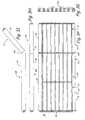
- FIG. 2is a top plan view of the transfer platform with its conveyor surface in place.
- FIG. 3Ais a top plan view of the transfer platform with its conveyor surface removed revealing rollers, roller banks, and a roller frame.
- FIG. 3Bis a top plan view of the transfer platform, according to an embodiment having a tapered edge, with the conveyor surface removed revealing rollers, roller banks, and a roller frame.
- FIG. 3Cis an end elevation view of the transfer platform of FIG. 3 B.
- FIG. 3Dis a top plan view of the transfer platform, according to one embodiment, with the conveyor surface removed revealing a low-friction platform in place of roller banks.
- FIG. 3Eis a lateral sectional elevation view of the transfer platform of FIG. 3D , taken along the line 3 E— 3 E.
- FIG. 3Fis a top plan view of the transfer platform, according to one embodiment capable of being inclined for patient comfort, with the conveyor surface removed revealing rollers, roller banks, and a roller frame.
- FIG. 3Gis an end elevation view of the transfer platform of FIG. 3 F.
- FIG. 3His a side elevation view of the transfer platform of FIG. 3F with the inclinable roller bank in the flat position.
- FIG. 3Iis a side elevation view of the transfer platform of FIG. 3F with the inclinable roller bank in the inclined position.
- FIG. 3Jis a lateral cross-sectional elevation of some of the rollers, according to one embodiment, where the conveyor surface travels on rollers that are surrounded by a soft resilient material for creating a soft, comfortable resting surface for the patient.
- FIG. 3Kis a lateral cross-sectional elevation of some of the rollers, according to one embodiment, where at least a portion of the conveyor surface is padded to create a soft, comfortable resting surface for the patient.
- FIG. 3Lis a lateral end elevation of some of the rollers, according to one embodiment, where at least a portion of the conveyor surface is padded by a series of soft ribs, which each run longitudinally across the conveyor surface generally parallel to the longitudinal axis of the rollers.
- FIG. 3Mis an enlarged lateral end elevation of the soft ribs depicted in FIG. 3 L.
- FIG. 3Nis the same lateral end elevation as FIG. 3 M and depicts the soft ribs in a collapsed state.
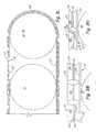
- FIG. 4is a cross-sectional plan view of a tension extension device.
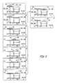
- FIG. 5is a latitudinal cross-sectional elevation view of a slotted sleeve channel end containing a transfer arm containing a carriage wheel.
- FIG. 6is a longitudinal cross-sectional elevation view of the unexposed end of a transfer arm within a slotted sleeve channel end.
- FIGS. 7A and 7Bare flow charts illustrating use of the patient transfer and transport device according to one embodiment of the present invention.
- FIG. 8schematically depicts the series of steps taken to transfer a patient from a hospital bed onto the patient transfer and transport device.
- FIG. 9schematically depicts the series of steps taken to transfer a patient from the patient transfer and transport device to a hospital bed.
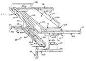
- FIG. 1is a perspective view of a patient transfer and transport device 1 , according to one embodiment of the present invention.
- the patient transfer and transport device 1has two transfer arms 10 a , 10 b , a platform receiving frame 20 , a transfer platform 30 , two support posts 50 a , 50 b , and a base 60 .
- the base 60 and the support posts 50 a , 50 bsupport the frame 20 at a desirable height.
- the transfer arms 10 a , 10 bare attached to the frame 20 and support the transfer platform 30 during lateral motion away from the frame 20 .
- the platform receiving frame 20has a first end 21 a , a second end 21 b , an enclosed side 22 a , and an open side 22 b .
- the ends 21 a , 21 bare slotted-sleeve channels, as further explained below.
- a rail handle 23 ais mounted on the first end 21 a .
- a throttle rail handle 23 bis mounted on the second end 21 b .
- One of each of the transfer arms 10 a , 10 bis slidably mounted within each end 21 a , 21 b .
- Each transfer arm 10 a , 10 bis capable of being extended linearly, in a generally horizontal manner, out of its respective end 21 a , 21 b , away from the platform receiving frame 20 , on the open side 22 b of the frame 20 .
- the transfer platform 30is located within the platform receiving frame 20 and is capable of being linearly translated, in a generally horizontal manner, through the open side 22 b of the platform receiving frame 20 , while being supported by the two transfer arms 10 a , 10 b .
- the enclosed side 22 a and the open side 22 bwill each have an integrated safety rail 24 to prevent the patient from rolling off of the transfer and transport device 1 .
- the transfer and transport device 1further includes an actuator 25 for causing motion of the transfer arms 10 a , 10 b .
- the actuator 25is a linear actuator.
- the transfer platform 30includes a locking mechanism for preventing linear motion of the transfer platform 30 within the transfer arms 10 a , 10 b.
- FIG. 2shows a top plan view of the transfer platform 30 , including a conveyor surface 36
- FIG. 3Ashows a top plan view of the transfer platform 30 , with the conveyor surface 36 removed.
- the transfer platform 30includes a roller frame 31 and a multitude of rollers 32 .
- the transfer platformincludes three roller banks 33 . In other embodiments more or fewer roller banks 33 are used. Depending on the strength of the rollers 32 , multiple banks 33 may be required to provide a sufficiently strong bed to support the patient.
- the transfer platform 30includes at least one drive roller 34 . In another embodiment, no drive roller 34 is included.
- the transfer platform 30also includes a tension roller 35 for maintaining tension on a conveyor surface 36 . In another embodiment, two tension rollers are included. In one embodiment, the drive roller 34 is also equipped to serve as a tension roller.
- FIGS. 2 and 3Afurther show a multitude of carriage wheels 39 , extending from each end of the transfer platform 30 .
- the rollers 32are generally parallel to each other and to the longitudinal dimension of the transfer platform 30 .
- the rollers 32are pivotably mounted within the roller frame 31 and are tightly spaced to support the patient.
- One embodiment of the inventionwould have a single roller bank 33 of rollers 32 , each roller 32 running the full length of the patient transfer platform 30 uninterrupted.
- two or more roller banks 33span the length of the patient transfer platform 30 , to minimize the stresses on the connections between the rollers 32 and the roller frame 31 .
- the roller framewould have intermediate bracing members 37 that would separate each roller bank 33 from the other and would help support the ends of the rollers 32 .
- the roller frame 31has two ends 38 a , 38 b and two sides 38 c , 38 d .
- a conveyor surface 36spans the roller frame 31 between the ends 38 a , 38 b and surrounds the entire roller frame 31 in one continuous belt enclosing the sides 38 c , 38 d and the roller banks 33 .
- the conveyor surface 36is washable for sanitizing purposes and is capable of being rotated around the roller frame 31 .
- the conveyor surface 36rides on the drive roller 34 , the tension roller 35 , and the rollers 32 of the roller banks 33 as the conveyor surface 36 rotates around the roller frame 31 . In one embodiment, as illustrated in FIG.
- 3Jwhich is a lateral cross-sectional elevation of some of the rollers 32 , 34 , 35 in the roller frame 31 , the conveyor surface 36 travels on rollers 32 , 34 , 35 that are surrounded by a soft resilient material 32 a (such as one or more layers of foam or rubber) for creating a soft, comfortable resting surface.
- the safety rail 24is mounted to the roller frame 31 , such that when the transfer platform 30 translates linearly, the safety rail 24 moves with it.
- the transfer platform 30includes a tapered leading edge 99 to assist in loading and unloading the patient.
- the tapered leading edge 99is created by using a set of rollers 100 having diameters that decrease toward the leading edge 99 .
- the tapered leading edge 99is created by using a tapered low-friction material ending in a roller at the tapered leading edge 99 .
- the transfer platform 30includes a shield 102 that extends along the bottom surface of the platform 30 , below the conveyor surface 36 and acts to prevent any sheets or clothing on the patient's bed from being pulled off the bed by the conveyor surface 36 .
- a low-friction platform 104is substituted in place of the roller banks 33 .
- the drive roller 34 and the tension roller 35are retained.
- the conveyor surface 36rides on the low-friction platform 104 , the drive roller 34 and the tension roller 35 .
- the low-friction platform 104has a soft resilient surface to provide the patient with a soft or cushioned surface on which to rest.
- the low-friction platform 104may have one or more layers of foam or rubber to provide a soft resilient surface.
- the transfer platform 30does not include the carriage wheels 39 , but instead is coupled directly to the transfer arms 10 a , 10 b . In this embodiment, the transfer platform extends laterally from the frame 20 when the transfer arms 10 a , 10 b are extended.
- the transfer platform 30is adapted to incline for patient comfort.
- the roller frame 31has a stationary roller bank 105 and an inclinable roller bank 107 , which includes a hinge 106 located at a desired pivot point.
- FIG. 3Hshows the transfer platform 30 in a flat position with the inclinable roller bank 107 in the flat position.
- FIG. 3Ishows the transfer platform 30 in the inclined position with the inclinable roller bank 107 in an inclined position.
- the stationary roller bank 105 and the inclinable roller bank 107each have their own separate independently driven drive rollers 34 and their own separate tension rollers 35 .
- the stationary roller bank 105 and the inclinable roller bank 107each have their own separate conveyor surfaces 36 .
- a single conveyor surface 36encompasses both roller banks 105 , 107 , and the conveyor surface 36 simply flexes at the hinge 106 as the hinge pivots 106 between the flat and inclined positions.
- there are two inclinable roller banks 107one for elevating the head and shoulders of the patient and the other for elevating the feet and legs of the patient.
- the transfer platform 30further includes a replaceable cover adapted to mount to and cover the conveyor surface 36 .
- the replaceable coveris adapted to absorb any of the patient's bodily fluids that may exit the patient during the transfer and transport process.
- the replaceable coveracts to protect the conveyor surface 36 .
- the replaceable coveris disposable such that a new replaceable cover is used with each patient transfer and transport process.
- the replaceable coveris connected to the conveyor using an adhesive.
- the replaceable coveris connected to the conveyor using a hook-and-loop attachment mechanism.
- hook-and-loop attachment stripsextend around the entire periphery of the transfer platform, placed in at least two locations, such that the strips are oriented in-line with the shear force between the conveyor surface 36 and the replaceable cover.
- the conveyor surface 36is padded to create a soft, comfortable resting surface for the patient.
- the padding 36 ais one or more layers of foam or rubber.
- the padding 36 ais a honeycomb structure, a system of chambers and pathways, or a series of tubes permanently filled with air, which results in an air mattress arrangement.
- the padding 36 ais a honeycomb structure, a system of chambers and pathways, or series of tubes wherein air is pumped into or vacuumed out of the honeycomb structure 36 a by a compressor/vacuum pump located on the base 60 of the patient transfer and transport device 1 . This allows the operator to adjust the level of firmness to meet the patient's desires.
- FIG. 3Lwhich is a lateral end elevation of some of the rollers 32 , 34 , 35 in the roller frame 31
- at least a portion of the conveyor surface 36is padded by a series of soft ribs 120 , which each run longitudinally across the conveyor surface 36 , generally parallel to the longitudinal axis of the rollers 32 , 34 , 35 .
- only part of the conveyor surfaceis covered with the ribs 120 .
- substantially all of conveyor surface 36is covered with the ribs 120 .
- These ribs 120create a soft, comfortable resting surface for the patient.
- the soft ribs 120are one or more layers of foam or rubber.
- each soft rib 120is a tube permanently filled with air, which results in an air mattress arrangement.
- each soft rib 120is a tube wherein air is pumped into or vacuumed out of the soft ribs 120 by a compressor/vacuum pump located on the base 60 of the patient transfer and transport device 1 . This allows the operator to adjust the level of firmness to meet the patient's desires.
- each soft rib 120is interconnected to the ends of its adjacent soft ribs 120 by an air canal 122 .
- the air canals 122provide a path between the compressor/vacuum pump and the soft ribs 120 by which air is pumped into or vacuumed out of all of the soft ribs 120 at the same time.
- each soft rib 120has a top 121 , a bottom 123 , and a concave wall 124 .
- the concave wall 124forms the continuous vertical perimeter wall of each soft rib 120 .
- a crease line 126is located at the approximate top-to-bottom center of the concave wall 124 .
- the crease line 126facilitates the concave wall 124 collapsing in towards the interior of the soft rib 120 as air is vacuumed from the soft rib 120 .
- the top 121 of each soft rib 120displaces essentially vertically towards its respective bottom 123 when each soft rib 120 is collapsed into the collapsed position as shown in FIG. 3 N. This allows each soft rib 120 to collapse into a repeatable compact collapsed position, which facilitates the free travel of the conveying surface 36 about the roller frame 31 .
- soft ribs 120are depicted as having concave walls 124 and flat tops 121 , those skilled in the art will recognize that the soft ribs may have square, circular or other types of cross-sections.
- the configuration of soft ribs 120 illustratedis provided only for representative purposes and should not be interpreted as limiting the disclosed invention.
- the soft resilient rollers 32 , 34 , 35 , illustrated in FIG. 3Jare combined with one of the padded conveyor surfaces 36 illustrated in FIGS. 3K and 3L .
- the above-described soft resilient low-friction platform 104is combined with one of the padded conveyor surfaces 36 illustrated in FIGS. 3K and 3L .
- the conveyor surface 36may be rotated manually in either direction. In another embodiment, the conveyor surface 36 is rotated in either direction via an electric motor. In one embodiment, the conveyor surface 36 is rotated by one or more drive rollers 34 having integral electric motors within the drive rollers 34 .
- the conveyor surface 36may be locked by a locking mechanism to prevent the conveyor surface 36 from rotating.
- This locking mechanismmay be manually or electrically operated.
- all rollers 32are located within the boundaries of the roller frame 31 formed by its ends 38 a , 38 b and sides 38 c , 38 d .
- the drive roller 34 and the tension roller 35are located outside the boundaries formed by the sides 38 c , 38 d .
- the drive roller 34 and the tension roller 35are mounted on extensions of the two ends 38 a , 38 b .
- the extensions that support the drive roller 34are called drive extensions 40 .
- the extensions that support the tension roller 35are called tension extensions 41 .
- the tension roller 35is used to maintain the proper tension in the conveyor belt as will be explained below.
- the drive roller 34is connected to an electric motor and causes the conveyor surface 36 to rotate. In another embodiment, where the drive roller 34 is not powered by a motor, the conveyor surface is rotated manually.
- FIG. 4shows a cross-sectional plan view of the tension extensions 41 of the transfer platform 30 , according to one embodiment of the present invention.
- the tension extensions 41are comprised of a telescoping shell 42 that is capable of telescoping over or off of an inner member 43 , which is the tip of the end 38 a , 38 b of the roller frame 31 .
- the telescoping shell 42has an enclosed end 44 through which a threaded rod 45 is pivotably secured.
- the threaded rod 45runs down through the center of the telescoping shell 42 and is threadably engaged with the threaded hole 46 in the end of the inner member 43 .
- the threaded rod 45can then be rotated to extend or retract the telescoping shell 42 of the tension extension 41 in order to reduce or increase slack in the conveyor surface 36 .
- maintaining the proper tension in the conveyor surface 36 by extending the tension roller 35 via the tension extensions 41will provide the necessary contact between the drive roller 34 and the conveyor surface 36 to allow the drive roller 34 to cause the conveyor surface 36 to rotate around the roller frame 31 .
- proper adjustment of the tension in each tension extension 41will prevent the conveyor surface 36 from skewing off of the surface of the rollers 32 as the conveyer surface 36 rotates.
- the tension maintenance mechanism disclosed in this specificationis just one of many similar configurations that are well known in the art. The tension maintenance mechanism illustrated here is only provided for representative purposes. In other embodiments, other known tension maintenance techniques are used.
- FIG. 5 and FIG. 6show sectional views of the transfer arms 10 a , 10 b , according to one embodiment of the present invention.
- the transfer arms 10 a , 10 bare slidably mounted within each slotted sleeve channel end 21 a , 21 b .
- Each transfer arm 10 a , 10 bis capable of being horizontally extended out of its respective slotted sleeve channel end 21 a , 21 b , away from the frame 20 , on the open side 22 b of the frame 20 .
- the transfer arms 10 a , 10 bmay be extended and retracted manually.
- the transfer arms 10 a , 10 bare automatically extended and retracted.
- the transfer arms 10 a , 10 bare extended or retracted by the linear actuator 25 located adjacent to each slotted sleeve channel end 21 a , 21 b .
- the linear actuators 25act on the transfer arms 10 a , 10 b via hydraulic or pneumatic rams, levers, gears 47 (shown in phantom-lines in FIG. 1 ) or screws, or other mechanical means of transferring force.
- each linear actuator 25has an integral electric motor for operating a system of gears 47 and gear racks, screws, and/or levers to cause the transfer arms 10 a , 10 b to extend or retract.
- an electric hydraulic or pneumatic pumpprovides pressure to the rams of the actuators 25 to cause the transfer arms 10 a , 10 b to extend or retract.
- a locking mechanismis provided for locking each transfer arm 10 a , 10 b in place to prevent its horizontal translation.
- the locking mechanismmay be either manually or electrically operated.
- a low profile roller 11is mounted on the exposed end of each transfer arm 10 a , 10 b .
- each low profile roller 11is fitted with a contact sensor that indicates when the low profile roller 11 has made sufficiently solid contact with the top surface of the hospital bed to facilitate the patient transfer.
- the sensorprovides an input to the transfer arm control system.
- each unexposed end (i.e., the end that always remains within the slotted sleeve channel end 21 a , 21 b ) of the transfer arm 10 a , 10 bhas tapered edges 15 to allow the carriage wheels 39 to easily roll into or out of the transfer arms 10 a , 10 b when the transfer arms 10 a , 10 b are in their extended position.
- Each transfer arm 10 a , 10 bhas one carriage wheel slot 13 that runs nearly the full length of the transfer arm 10 a , 10 b .
- Each carriage wheel slot 13opens horizontally towards the center of the transfer platform 30 .
- each slotted sleeve channel end 21 a , 21 bhas one carriage wheel slot 14 that runs nearly the full length of the slotted sleeve channel end 21 a , 21 b .
- Each carriage wheel slot 14 of the slotted sleeve channel end 21 a , 21 balso opens horizontally towards the center of the transfer platform 30 and aligns with and matches dimensionally the carriage wheel slot 13 of its respective transfer arm 10 a , 10 b , as can be seen in FIG. 5 and FIG. 6 .
- multiple carriage wheels 39are rollably mounted on each roller frame end 38 a , 38 b , the axis of each carriage wheel 39 being generally parallel to the long dimension of the transfer platform 30 .
- the carriage wheels 39are located within the carriage wheel slots 13 of the transfer arms 10 a , 10 b and the carriage wheel slots 14 of the slotted sleeve channel ends 21 a , 21 b .
- the carriage wheels 39roll in the carriage wheel slots 13 , 14 , thus allowing the transfer platform 30 to translate linearly, in a generally horizontal manner, out through the open side 22 b of the frame 20 when the transfer arms 10 a , 10 b are in the extended position as shown in FIG. 1 .
- the operatormanually translates the transfer platform 30 horizontally.
- the transfer platform 30is powered by an electric motor.
- a cam lock systemis provided on each transfer arm 10 a , 10 b to lock the carriage wheels 39 to prevent the transfer platform 30 from translating horizontally.
- each support post 50 a , 50 bis a hydraulic or pneumatic ram, which is pumped manually or by an electric pump in order to raise or lower the frame 20 .
- Those skilled in the artwill readily recognize other means of extending or shortening the support posts 50 a , 50 b in order to raise or lower the frame 20 .
- These meansinclude mechanical force transferring devices like a spur-gear and gear rack combination, a worm-gear screw jack, or other similar means for transferring force mechanically. All of these devices may be powered by one or more electric motors.
- the support posts 50 a , 50 bwith their accompanying lifting devices, are replaced with a scissor lift as is well known in the art.
- the base 60is comprised of two long braces 61 a , 61 b , two short braces 62 a , 62 b , and two post platforms 63 a , 63 b .
- Each support post 50 a , 50 bis supported by and centered on one post platform 63 a , 63 b .
- the two long braces 61 a , 61 brun parallel to each other and horizontally between their perpendicular connections to the two short braces 62 a , 62 b .
- Each post platform 63 a , 63 brests horizontally on and is connected to the top horizontal surfaces of the long braces 61 a , 61 b and the short braces 62 a , 62 b , near the intersections of the braces 61 a , 61 b , 62 a , 62 b .
- other structural configurationsare employed.
- the transfer and transport device 1includes one or more batteries 65 coupled to the base 60 .
- the batteries 65are secured in battery trays 64 and provide power for the various electric motors on the transfer and transport device 1 .
- the batteries 65also provide ballast to prevent the transfer and transport device 1 from tipping.
- four 12-volt gel batteriesare included.
- the base 60includes castors 66 , which are lockable and capable of pivoting 360 degrees.
- the transfer and transport device 1includes a drive wheel 67 mounted to the base 60 .
- the drive wheel 67has an electric motor and gearbox in its hub.
- the drive wheel 67is mounted on a trailing arm suspension 68 .
- the trailing arm suspension 68is spring loaded and attached to the base 60 .
- the drive wheel 67may be raised or lowered by manual or motorized means. Raising the drive wheel 67 completely will allow for increased ease of maneuverability.
- the electrical systemwill have the following features: a programmable motor controller; a built-in battery charger; a control panel with status indicators; a touch sensitive throttle 26 to control the drive wheel 67 ; a handheld remote control to control all transfer functions; an emergency shutoff; and multiple safety interlocks.
- the touch sensitive throttle 26is ergonomically contoured and located on the throttle rail handle 23 b .
- the touch sensitive throttle 26is used by the operator to cause the drive wheel 67 to go forward or backward.
- Speed and directionis proportional to the magnitude and direction of the force applied to the touch sensitive throttle 26 by the operator. For example, if the operator pushes forward on the throttle 26 , the patient transfer and transport device 1 will go forward.
- the device 1includes a microprocessor for executing code to control one or more aspects of the operation of the device 1 .
- the operatorwill be able to perform one or more of the following maneuvers: extend and retract the transfer arms 10 a , 10 b linearly and in a generally horizontal manner, raise or lower the transfer platform 30 by actuating the hydraulic or pneumatic rams in the support posts 50 a , 50 b , translate generally horizontally and linearly the transfer platform 30 , and rotate the conveyor surface 36 .
- the remote controlcommunicates with the microprocessor on the device 1 via wireless communication, such as radio frequency or infrared communication.
- the remote controlcommunicates with the microprocessor on the device 1 via hardwired connection.
- electronic safety interlocksare provided for the integrated safety rails 24 , the drive wheel 67 motor, the hydraulic/pneumatic rams in the support posts 50 a , 50 b , the motor for the conveyor surface 36 , the linear actuator 25 for the transfer arms 10 a , 10 b , and the motor that moves the transfer platform 30 generally horizontally.
- Status indicators on the control panelin addition to indicating the battery charge and other useful information, will indicate the status of these safety interlocks.
- FIGS. 7A and 7Bare flow charts showing a method 70 of using the patient transfer and transport device 1 , according to one embodiment of the present invention, to transfer a patient from a hospital bed onto the patient transfer and transport device 1 .
- FIG. 8schematically depicts the series of steps taken in the method 70 to transfer a patient from a hospital bed onto the patient transfer and transport device 1 .
- FIG. 9schematically depicts the series of steps taken to transfer a patient from the patient transfer and transport device 1 to a hospital bed (i.e., FIG. 9 depicts the method 70 in reverse).
- any reference to bed or hospital bedtherefore, also includes other medical patient support surfaces including procedural surfaces.
- the operator of the transfer and transport device 1maneuvers the empty transfer and transport device 1 into position along side the patient's bed 150 , until the open side 22 b is adjacent to the side of the bed 150 and the longitudinal centers of the patient 152 and the device 1 coincide (block 72 ; block A).
- the operatoradjusts the support posts 50 a , 50 b to adjust the height of the transfer and transport device 1 so that the transfer arms 10 a , 10 b will clear the top of the bed 150 when extended (block 74 ; block A).
- the operatorlowers the integrated safety rail 24 of the device 1 on the open side 22 b and locks the castors 66 to prevent movement of the transfer and transport device 1 during patient transfer (block 76 ; block A).
- the operatorutilizes the remote control to extend the transfer arms 10 a , 10 b generally horizontally until the low profile roller 11 on the end of each transfer arm 10 a , 10 b is located near the centerline of the patient's hospital bed 150 (block 78 ; block B). At this point, the transfer arms 10 a , 10 b will straddle the patient 152 end to end.
- the operatoruses the remote control to lower the transfer platform 30 until the contact sensors located on the low profile rollers 11 indicate solid contact between the patient's bed top and the transfer arms 10 a , 10 b (block 80 ; block C).
- Extending the transfer arms 10 a , 10 b so that the low profile rollers 11 are at least as far as the center of the bed 150 and lowering the transfer arms 10 a , 10 b solidly onto the bed topwill allow the patient's bed 150 to help support the transfer arms 10 a , 10 b , thus preventing the transfer and transport device 1 from tipping over during the loading of the patient 152 onto the transfer platform 30 .
- the operatormay use the remote control to cause the compressor or compressed air storage tank to inflate the padded conveyor surface 36 prior to loading the patient onto the transfer platform.
- the operatormay wait to inflate the padded conveyor surface 36 until after the patient is resting on the conveyor surface 36 .
- the operatorlog-rolls the patient 152 to expose the patient's back to the transfer and transport device 1 and extends the transfer platform 30 linearly, in a generally horizontal manner, out of its transport position within the frame 20 until the edge of the transfer platform 30 reaches the patient's back (block 82 ; block D).
- the operatorthen locks the transfer platform 30 to prevent its horizontal linear motion, lowers the patient 152 onto the edge of the transfer platform 30 , and causes the conveyor surface 36 to rotate in a direction that will pull the patient 152 up onto the transfer platform 30 , until the patient 152 is centered on the transfer platform 30 (block 84 ; blocks E and F).
- the operatorthen uses the remote control to unlock and move the transfer platform 30 linearly, in a generally horizontal manner, back to its transport position within the frame 20 , where it is locked both linearly and rotationally (block 86 ; block G).
- a sensoris contacted, automatically stopping the movement of the transfer platform 30 .
- the operatorthen uses the remote control to raise the device 1 to reduce the pressure on the transfer arms 10 a , 10 b and to retract the transfer arms 10 a , 10 b (block 88 ; blocks H and I).
- the castors 66are unlocked and the transfer and transport device 1 is maneuvered away from the patient's bed.
- the remote controlis then used to lower the transfer platform 30 to transport height and to lower the drive wheel 67 .
- the operatorthen activates the drive wheel 67 to propel the device 1 forward by pushing on the touch sensitive throttle 26 located on the throttle rail handle 23 b .
- the drive wheel 67will propel the device 1 backwards when the operator pulls on the touch sensitive throttle 26 .
- the touch sensitive throttle 26has proportional control.
- the rotational speed of the drive wheel 67will be relative to the magnitude of the force applied to the throttle 26 by the operator. For example, increasing the force applied to the throttle 26 results in increased speed while decreasing the force results in decreased speed.
- the transfer and transport device 1the patient can then be transported to another location and transferred to another bed by reversing the above-recited steps (see FIG. 9 , blocks A-I).
- the microprocessoris programmed to automatically cause many of the above steps to be performed to assist a single operator in performing the transfer process.
- the remote controlincludes an “extend arms” button, which triggers the microprocessor to cause extension of the arms and lowering of the platform until a signal is received from the sensor indicating contact with the bed.
- the remote controlincludes an “extend platform” button, which triggers the microprocessor to unlock the transfer platform, linearly translate the platform out, in a generally horizontal manner, onto the transfer arms, lock the platform linearly, and initiate rotation of the conveying surface.
- the remote controlincludes a “retract platform” button, which triggers the microprocessor to stop rotation of the conveying surface, unlock the platform linearly, retract the platform linearly, in a generally horizontal manner, to its home position, and relock the platform both linearly and rotationally.
- the remote controlincludes a separate button to start and stop rotation of the conveying surface.
- the remote controlincludes a separate button to actuate the compressor and/or compressed air storage tank to cause the padded conveyor surface to inflate.
- the remote controlincludes a separate button to actuate the vacuum pump to deflate the padded conveyor surface 36 .
- the remote controlincludes other configurations of buttons, as would be apparent to one skilled in the art.
Landscapes
- Health & Medical Sciences (AREA)
- Nursing (AREA)
- Life Sciences & Earth Sciences (AREA)
- Animal Behavior & Ethology (AREA)
- General Health & Medical Sciences (AREA)
- Public Health (AREA)
- Veterinary Medicine (AREA)
- Engineering & Computer Science (AREA)
- Mechanical Engineering (AREA)
- Invalid Beds And Related Equipment (AREA)
- Intermediate Stations On Conveyors (AREA)
Abstract
Description
Claims (41)
Priority Applications (3)
| Application Number | Priority Date | Filing Date | Title |
|---|---|---|---|
| US10/369,210US6854137B2 (en) | 2002-02-18 | 2003-02-18 | Patient transfer and transport bed |
| US11/017,974US7000268B2 (en) | 2002-02-18 | 2004-12-21 | Patient transfer and transport bed |
| US11/332,663US7578011B2 (en) | 2002-02-18 | 2006-01-12 | Patient transfer and transport bed |
Applications Claiming Priority (2)
| Application Number | Priority Date | Filing Date | Title |
|---|---|---|---|
| US35791102P | 2002-02-18 | 2002-02-18 | |
| US10/369,210US6854137B2 (en) | 2002-02-18 | 2003-02-18 | Patient transfer and transport bed |
Related Child Applications (1)
| Application Number | Title | Priority Date | Filing Date |
|---|---|---|---|
| US11/017,974ContinuationUS7000268B2 (en) | 2002-02-18 | 2004-12-21 | Patient transfer and transport bed |
Publications (2)
| Publication Number | Publication Date |
|---|---|
| US20030213064A1 US20030213064A1 (en) | 2003-11-20 |
| US6854137B2true US6854137B2 (en) | 2005-02-15 |
Family
ID=27757675
Family Applications (2)
| Application Number | Title | Priority Date | Filing Date |
|---|---|---|---|
| US10/369,210Expired - LifetimeUS6854137B2 (en) | 2002-02-18 | 2003-02-18 | Patient transfer and transport bed |
| US11/017,974Expired - LifetimeUS7000268B2 (en) | 2002-02-18 | 2004-12-21 | Patient transfer and transport bed |
Family Applications After (1)
| Application Number | Title | Priority Date | Filing Date |
|---|---|---|---|
| US11/017,974Expired - LifetimeUS7000268B2 (en) | 2002-02-18 | 2004-12-21 | Patient transfer and transport bed |
Country Status (5)
| Country | Link |
|---|---|
| US (2) | US6854137B2 (en) |
| EP (1) | EP1480591A4 (en) |
| AU (1) | AU2003217589A1 (en) |
| CA (1) | CA2473919A1 (en) |
| WO (1) | WO2003070143A2 (en) |
Cited By (44)
| Publication number | Priority date | Publication date | Assignee | Title |
|---|---|---|---|---|
| US20060185091A1 (en)* | 2005-02-22 | 2006-08-24 | Jackson Roger P | Modular multi-articulated patient support system |
| US20060213007A1 (en)* | 2005-03-14 | 2006-09-28 | Frederic Palay | Patient transfer system with associated frames and lift carts |
| US20060236453A1 (en)* | 2005-04-22 | 2006-10-26 | Jao Chen-Chuan D R | Equipment for moving patient without changing patient's pose |
| US20070251004A1 (en)* | 2006-04-27 | 2007-11-01 | Wang Xiao D | Automatic patient transfer system |
| US20080034495A1 (en)* | 2006-01-06 | 2008-02-14 | Stidd Raymond E | Patient gurney |
| US7487559B1 (en) | 2004-10-05 | 2009-02-10 | Denosky James M | Patient transfer device |
| US20090158523A1 (en)* | 2007-12-12 | 2009-06-25 | Ergo-Asyst Technology Llc | Mobile Cantilever Transfer Device |
| US20090249544A1 (en)* | 2008-04-04 | 2009-10-08 | Ergo-Asyst Technology Llc | Multi-functional patient transfer device |
| US8719978B2 (en)* | 2012-02-29 | 2014-05-13 | Siemens Aktiengesellschaft | Patient support apparatus and medical imaging apparatus comprising the patient support apparatus |
| US9180062B2 (en) | 2005-02-22 | 2015-11-10 | Roger P. Jackson | Patient positioning support structure |
| US9186291B2 (en) | 2005-02-22 | 2015-11-17 | Roger P. Jackson | Patient positioning support structure with trunk translator |
| US9226865B2 (en) | 2005-02-22 | 2016-01-05 | Roger P. Jackson | Patient positioning support structure |
| US9265679B2 (en) | 2005-02-22 | 2016-02-23 | Roger P Jackson | Cantilevered patient positioning support structure |
| US9295433B2 (en) | 2005-02-22 | 2016-03-29 | Roger P. Jackson | Synchronized patient elevation and positioning apparatus for use with patient positioning support systems |
| US9301897B2 (en) | 2005-02-22 | 2016-04-05 | Roger P. Jackson | Patient positioning support structure |
| WO2016054633A1 (en)* | 2014-10-03 | 2016-04-07 | Ilift2Assist, Llc | Patient transfer device |
| US9308145B2 (en) | 2005-02-22 | 2016-04-12 | Roger P. Jackson | Patient positioning support structure |
| US9339430B2 (en) | 2006-05-05 | 2016-05-17 | Roger P. Jackson | Patient positioning support apparatus with virtual pivot-shift pelvic pads, upper body stabilization and fail-safe table attachment mechanism |
| US9358170B2 (en) | 2007-10-22 | 2016-06-07 | Roger P Jackson | Surgery table apparatus |
| US9402775B2 (en) | 2014-07-07 | 2016-08-02 | Roger P. Jackson | Single and dual column patient positioning and support structure |
| US9468576B2 (en) | 2005-02-22 | 2016-10-18 | Roger P. Jackson | Patient support apparatus with body slide position digitally coordinated with hinge angle |
| US20160346148A1 (en)* | 2012-02-07 | 2016-12-01 | Roger P. Jackson | Fail-safe release mechanism for use with patient positioning support apparati |
| US9549863B2 (en) | 2014-07-07 | 2017-01-24 | Roger P. Jackson | Surgical table with pivoting and translating hinge |
| US9603764B2 (en) | 2014-02-11 | 2017-03-28 | Medline Industries, Inc. | Method and apparatus for a locking caster |
| US9642760B2 (en) | 2006-05-05 | 2017-05-09 | Roger P. Jackson | Patient positioning support apparatus with virtual pivot-shift pelvic pads, upper body stabilization and fail-safe table attachment mechanism |
| US9744087B2 (en) | 2005-02-22 | 2017-08-29 | Roger P. Jackson | Patient support apparatus with body slide position digitally coordinated with hinge angle |
| US9849054B2 (en) | 2005-02-22 | 2017-12-26 | Roger P. Jackson | Patient positioning support structure |
| US9968503B2 (en) | 2012-04-16 | 2018-05-15 | Allen Medical Systems, Inc. | Dual column surgical table having a single-handle unlock for table rotation |
| US10363189B2 (en) | 2015-10-23 | 2019-07-30 | Allen Medical Systems, Inc. | Surgical patient support for accommodating lateral-to-prone patient positioning |
| US10492973B2 (en) | 2015-01-05 | 2019-12-03 | Allen Medical Systems, Inc. | Dual modality prone spine patient support apparatuses |
| US10548793B2 (en) | 2016-06-14 | 2020-02-04 | Allen Medical Systems, Inc. | Pinless loading for spine table |
| US10561559B2 (en)* | 2015-10-23 | 2020-02-18 | Allen Medical Systems, Inc. | Surgical patient support system and method for lateral-to-prone support of a patient during spine surgery |
| US20200146912A1 (en)* | 2016-10-31 | 2020-05-14 | Margaret Gillespie | Lifting system with lifting device and cantilevered support platform |
| US10857054B2 (en) | 2015-11-13 | 2020-12-08 | Allen Medical Systems, Inc. | Person support apparatuses for subject repositioning |
| US10869798B2 (en) | 2006-05-05 | 2020-12-22 | Warsaw Orthopedic, Inc. | Patient positioning support apparatus with virtual pivot-shift pelvic pads, upper body stabilization and fail-safe table attachment mechanism |
| US11051770B2 (en) | 2005-02-22 | 2021-07-06 | Warsaw Orthopedic, Inc. | Patient positioning support structure |
| US11202731B2 (en) | 2018-02-28 | 2021-12-21 | Allen Medical Systems, Inc. | Surgical patient support and methods thereof |
| US11213448B2 (en) | 2017-07-31 | 2022-01-04 | Allen Medical Systems, Inc. | Rotation lockout for surgical support |
| US11471354B2 (en) | 2018-08-30 | 2022-10-18 | Allen Medical Systems, Inc. | Patient support with selectable pivot |
| US11628111B1 (en) | 2022-03-30 | 2023-04-18 | Able Innovations Inc. | Transfer device with platform plate having two-sided functionality |
| US12011399B2 (en) | 2013-08-28 | 2024-06-18 | Warsaw Orthopedic, Inc. | Patient positioning support apparatus with fail-safe connector attachment mechanism |
| US12208044B2 (en) | 2019-09-13 | 2025-01-28 | Medline Industries, Lp | Patient repositioning sheet, system, and method |
| US12274654B2 (en) | 2019-10-18 | 2025-04-15 | Able Innovations Inc. | Devices and methods for transferring an object |
| US12440396B2 (en) | 2023-03-29 | 2025-10-14 | Able Innovations Inc. | Transfer device with platform plate having two-sided functionality and treatment system |
Families Citing this family (29)
| Publication number | Priority date | Publication date | Assignee | Title |
|---|---|---|---|---|
| US7003819B2 (en)* | 2001-11-02 | 2006-02-28 | Weigand Nancy E | Patient-positioning device |
| US7603729B2 (en) | 2005-10-07 | 2009-10-20 | Conmedisys, Inc. | Patient lift and transfer device |
| WO2007044231A2 (en) | 2005-10-07 | 2007-04-19 | Conmedisys, Inc. | Patient lift and transfer device |
| US8214943B2 (en)* | 2005-10-07 | 2012-07-10 | Conmedisys, Inc. | Steering system for patient transfer device |
| US9107788B2 (en) | 2005-10-07 | 2015-08-18 | MediGlider Corp. | Cam mechanism to raise steering wheel of patient transfer device |
| US7685656B1 (en) | 2005-10-26 | 2010-03-30 | James Darrigo | Transfer device |
| US7478444B1 (en) | 2005-10-26 | 2009-01-20 | James Darrigo | Patient transfer device |
| WO2007067874A2 (en)* | 2005-12-05 | 2007-06-14 | Ahlman Scott M | Patient single surface system |
| ES2288799B2 (en)* | 2006-07-07 | 2008-08-01 | Jose Manuel Embil Fanjul | CAMILLA-CRANE FOR TRANSFER OF ENCAMADAS PEOPLE. |
| US20090144903A1 (en)* | 2007-12-06 | 2009-06-11 | Delvaux Andrew B | Cpr facilitating mattress |
| US8156582B2 (en) | 2008-04-08 | 2012-04-17 | Stryker Corporation | Patient repositioning system |
| KR20100134949A (en)* | 2009-06-16 | 2010-12-24 | 제양규 | Patient transfer device |
| DE102010008014A1 (en)* | 2010-02-15 | 2011-08-18 | Siemens Aktiengesellschaft, 80333 | Guidance system for medical equipment, medical equipment, mobile transport device and method |
| KR101150875B1 (en)* | 2010-03-04 | 2012-06-13 | 계명대학교 산학협력단 | Functional table for patient transportation |
| US8468623B2 (en)* | 2010-06-10 | 2013-06-25 | Richard A. Patterson | Lift chair |
| WO2012134429A1 (en)* | 2011-03-25 | 2012-10-04 | Mahdjohbi Mohammad Hassan | Multi purpose hospital bed |
| KR101355756B1 (en) | 2012-05-12 | 2014-01-27 | 제양규 | Patient Transfer Apparatus Using Side Safety Rails |
| CN104107123A (en)* | 2014-07-28 | 2014-10-22 | 周佩龙 | Preparing operation rapid transfer bed |
| US10413468B2 (en) | 2015-05-14 | 2019-09-17 | Stryker Corporation | Patient repositioning apparatus |
| CN106562853B (en)* | 2016-10-19 | 2018-01-02 | 青岛市市立医院 | A kind of Medical transport pushing bed |
| CN106618884B (en)* | 2016-10-19 | 2017-11-24 | 青岛市第三人民医院 | The automatic bed transport of high intensity |
| JOP20180051A1 (en)* | 2018-05-15 | 2019-11-15 | Jordan Univ Of Science And Technology | Patient transfer apparatus and method |
| US11154440B2 (en)* | 2019-07-19 | 2021-10-26 | Nelson Tyler | Patient litter basket with spin control |
| CN111345946B (en)* | 2020-04-25 | 2025-02-14 | 佛山晓微企业管理咨询有限公司 | Power mechanism for patient transfer bed |
| CN111588553B (en)* | 2020-06-22 | 2024-07-09 | 江苏富朗特医疗科技有限公司 | Electric power assisting device for medical sickbed |
| US12186253B2 (en) | 2021-01-19 | 2025-01-07 | University Of Utah Research Foundation | Trauma gurney with enhanced patient transfer capabilities |
| CN113017672B (en)* | 2021-03-01 | 2022-05-06 | 哈尔滨市鼎康医疗科技有限公司 | CT machine and its automatic conveying device |
| CN113413272B (en)* | 2021-06-18 | 2024-11-29 | 佳泰康医疗设备(广州)有限公司 | Medical transfer bed |
| EP4499013A1 (en)* | 2022-03-30 | 2025-02-05 | Able Innovations Inc. | Transfer device with platform plate having two-sided functionality |
Citations (15)
| Publication number | Priority date | Publication date | Assignee | Title |
|---|---|---|---|---|
| US2918681A (en)* | 1953-06-30 | 1959-12-29 | Fenimore E Davis | Patient transfer device |
| US3493979A (en)* | 1968-02-14 | 1970-02-10 | Advance Products Corp Of Ameri | Method and apparatus for moving objects |
| US3765037A (en)* | 1972-04-05 | 1973-10-16 | Diamondhead Corp | Apparatus for transferring objects |
| US3854152A (en)* | 1973-04-02 | 1974-12-17 | Ziskin H | Apparatus for transferring patients |
| US3967328A (en)* | 1974-09-06 | 1976-07-06 | Cox Ellis V | Load lifting and transferring device with multiple powered belts |
| US4073016A (en) | 1976-06-17 | 1978-02-14 | Mobilizer Medical Products, Inc. | Transfer mechanism |
| US4087873A (en)* | 1975-12-27 | 1978-05-09 | Hiroshi Ohkawa | Apparatus for moving objects |
| US4274168A (en) | 1979-09-17 | 1981-06-23 | Depowski Norma M | Patient transfer apparatus |
| US4761841A (en)* | 1987-05-11 | 1988-08-09 | Larsen Ralph E | Hospital gurney having a patient transfer device |
| US4794655A (en) | 1986-04-25 | 1989-01-03 | Agency Of Industrial Science & Technology | Truck type patient-moving device |
| US4839933A (en) | 1985-08-13 | 1989-06-20 | Plewright William B | Patient transfer and conveying vehicle |
| US4987623A (en) | 1990-01-26 | 1991-01-29 | Stryker Corporation | Hospital stretcher having patient transfer device and side rails with handle portions |
| US5197156A (en) | 1991-07-31 | 1993-03-30 | Stryker Corporation | Transfer board support lever and support post |
| US5937456A (en) | 1997-08-29 | 1999-08-17 | Norris; John F. | Device for transferring a patient to and from a hospital bed |
| US6427270B1 (en) | 1997-04-11 | 2002-08-06 | Jerry L. Blevins | Cantilevered mobile bed/chair apparatus for safety patient transfer |
Family Cites Families (8)
| Publication number | Priority date | Publication date | Assignee | Title |
|---|---|---|---|---|
| US2691782A (en)* | 1952-06-26 | 1954-10-19 | Richard M West | Patient-carrying vehicle for hospitals |
| US3597672A (en)* | 1968-12-30 | 1971-08-03 | Singer Co | Electrical drive systems for sewing machines |
| US3875599A (en)* | 1972-01-03 | 1975-04-08 | Milo F Mracek | Portable support for a bed patient |
| DE2626638A1 (en)* | 1976-06-14 | 1977-12-22 | Stierlen Maquet Ag | TRANSPORT DEVICE FOR RELOCATING LY PATIENTS, ESPECIALLY IN HOSPITALS |
| US4262375A (en)* | 1979-10-26 | 1981-04-21 | Lilienthal Alfred J | Patient transfer apparatus |
| US4873732A (en)* | 1988-10-24 | 1989-10-17 | Roberto Perez | Trauma stretcher |
| US5781943A (en)* | 1997-03-13 | 1998-07-21 | Moenning; Stephen P. | Medical table and method for moving a patient from a first position to a second position |
| US5855207A (en)* | 1997-05-29 | 1999-01-05 | Moenning; Stephen P. | Medical table assembly having a restrainment apparatus mounted thereto and an associated method of immobilizing object |
- 2003
- 2003-02-18EPEP03713544Apatent/EP1480591A4/ennot_activeWithdrawn
- 2003-02-18CACA002473919Apatent/CA2473919A1/ennot_activeAbandoned
- 2003-02-18WOPCT/US2003/004996patent/WO2003070143A2/ennot_activeApplication Discontinuation
- 2003-02-18AUAU2003217589Apatent/AU2003217589A1/ennot_activeAbandoned
- 2003-02-18USUS10/369,210patent/US6854137B2/ennot_activeExpired - Lifetime
- 2004
- 2004-12-21USUS11/017,974patent/US7000268B2/ennot_activeExpired - Lifetime
Patent Citations (15)
| Publication number | Priority date | Publication date | Assignee | Title |
|---|---|---|---|---|
| US2918681A (en)* | 1953-06-30 | 1959-12-29 | Fenimore E Davis | Patient transfer device |
| US3493979A (en)* | 1968-02-14 | 1970-02-10 | Advance Products Corp Of Ameri | Method and apparatus for moving objects |
| US3765037A (en)* | 1972-04-05 | 1973-10-16 | Diamondhead Corp | Apparatus for transferring objects |
| US3854152A (en)* | 1973-04-02 | 1974-12-17 | Ziskin H | Apparatus for transferring patients |
| US3967328A (en)* | 1974-09-06 | 1976-07-06 | Cox Ellis V | Load lifting and transferring device with multiple powered belts |
| US4087873A (en)* | 1975-12-27 | 1978-05-09 | Hiroshi Ohkawa | Apparatus for moving objects |
| US4073016A (en) | 1976-06-17 | 1978-02-14 | Mobilizer Medical Products, Inc. | Transfer mechanism |
| US4274168A (en) | 1979-09-17 | 1981-06-23 | Depowski Norma M | Patient transfer apparatus |
| US4839933A (en) | 1985-08-13 | 1989-06-20 | Plewright William B | Patient transfer and conveying vehicle |
| US4794655A (en) | 1986-04-25 | 1989-01-03 | Agency Of Industrial Science & Technology | Truck type patient-moving device |
| US4761841A (en)* | 1987-05-11 | 1988-08-09 | Larsen Ralph E | Hospital gurney having a patient transfer device |
| US4987623A (en) | 1990-01-26 | 1991-01-29 | Stryker Corporation | Hospital stretcher having patient transfer device and side rails with handle portions |
| US5197156A (en) | 1991-07-31 | 1993-03-30 | Stryker Corporation | Transfer board support lever and support post |
| US6427270B1 (en) | 1997-04-11 | 2002-08-06 | Jerry L. Blevins | Cantilevered mobile bed/chair apparatus for safety patient transfer |
| US5937456A (en) | 1997-08-29 | 1999-08-17 | Norris; John F. | Device for transferring a patient to and from a hospital bed |
Cited By (110)
| Publication number | Priority date | Publication date | Assignee | Title |
|---|---|---|---|---|
| US7487559B1 (en) | 2004-10-05 | 2009-02-10 | Denosky James M | Patient transfer device |
| US7752687B1 (en) | 2004-10-05 | 2010-07-13 | Denosky James M | Patient transfer device |
| US10881566B2 (en) | 2005-02-22 | 2021-01-05 | Warsaw Orthopedic, Inc. | Patient support apparatus with body slide position digitally coordinated with hinge angle |
| US9295433B2 (en) | 2005-02-22 | 2016-03-29 | Roger P. Jackson | Synchronized patient elevation and positioning apparatus for use with patient positioning support systems |
| US20060185091A1 (en)* | 2005-02-22 | 2006-08-24 | Jackson Roger P | Modular multi-articulated patient support system |
| US7343635B2 (en)* | 2005-02-22 | 2008-03-18 | Jackson Roger P | Modular multi-articulated patient support system |
| US9849054B2 (en) | 2005-02-22 | 2017-12-26 | Roger P. Jackson | Patient positioning support structure |
| US9757300B2 (en) | 2005-02-22 | 2017-09-12 | Roger P Jackson | Patient positioning support structure |
| US9364380B2 (en) | 2005-02-22 | 2016-06-14 | Roger P Jackson | Patient positioning support structure |
| US10695252B2 (en) | 2005-02-22 | 2020-06-30 | Warsaw Orthopedic, Inc. | Patient positioning support structure |
| US9636266B2 (en) | 2005-02-22 | 2017-05-02 | Roger P. Jackson | Synchronized patient elevation and positioning apparatus for use with patient positioning support systems |
| US10835438B2 (en) | 2005-02-22 | 2020-11-17 | Warsaw Orthopedic, Inc. | Modular multi-articulated patient support system |
| US9610206B2 (en) | 2005-02-22 | 2017-04-04 | Roger P. Jackson | Patient positioning support structure |
| US10500114B2 (en) | 2005-02-22 | 2019-12-10 | Warsaw Orthopedic, Inc. | Synchronized patient elevation and positioning apparatus for use with patient positioning support systems |
| US12127863B2 (en) | 2005-02-22 | 2024-10-29 | Warsaw Orthopedic, Inc. | Patient positioning support structure |
| US9180062B2 (en) | 2005-02-22 | 2015-11-10 | Roger P. Jackson | Patient positioning support structure |
| US9186291B2 (en) | 2005-02-22 | 2015-11-17 | Roger P. Jackson | Patient positioning support structure with trunk translator |
| US9198817B2 (en) | 2005-02-22 | 2015-12-01 | Roger P. Jackson | Patient positioning support structure |
| US9205013B2 (en) | 2005-02-22 | 2015-12-08 | Roger P. Jackson | Patient positioning support structure |
| US9211223B2 (en) | 2005-02-22 | 2015-12-15 | Roger P. Jackson | Patient positioning support structure |
| US9226865B2 (en) | 2005-02-22 | 2016-01-05 | Roger P. Jackson | Patient positioning support structure |
| US9265679B2 (en) | 2005-02-22 | 2016-02-23 | Roger P Jackson | Cantilevered patient positioning support structure |
| US9289342B2 (en) | 2005-02-22 | 2016-03-22 | Roger P. Jackson | Patient positioning support structure |
| US11051770B2 (en) | 2005-02-22 | 2021-07-06 | Warsaw Orthopedic, Inc. | Patient positioning support structure |
| US9301897B2 (en) | 2005-02-22 | 2016-04-05 | Roger P. Jackson | Patient positioning support structure |
| US12076281B2 (en) | 2005-02-22 | 2024-09-03 | Warsaw Orthopedic, Inc. | Modular multi-articulated patient support system |
| US9308145B2 (en) | 2005-02-22 | 2016-04-12 | Roger P. Jackson | Patient positioning support structure |
| US11547622B2 (en) | 2005-02-22 | 2023-01-10 | Warsaw Orthopedic, Inc. | Synchronized patient elevation and positioning apparatus for use with patient positioning support systems |
| US9510987B2 (en) | 2005-02-22 | 2016-12-06 | Roger P. Jackson | Patient positioning support structure with trunk translator |
| US9744087B2 (en) | 2005-02-22 | 2017-08-29 | Roger P. Jackson | Patient support apparatus with body slide position digitally coordinated with hinge angle |
| US11679051B2 (en) | 2005-02-22 | 2023-06-20 | Warsaw Orthopedic, Inc. | Patient positioning support structure |
| US9456945B2 (en) | 2005-02-22 | 2016-10-04 | Roger P. Jackson | Patient positioning support structure |
| US9468576B2 (en) | 2005-02-22 | 2016-10-18 | Roger P. Jackson | Patient support apparatus with body slide position digitally coordinated with hinge angle |
| US9504622B2 (en) | 2005-02-22 | 2016-11-29 | Roger P. Jackson | Patient positioning support structure with trunk translator |
| US20060213007A1 (en)* | 2005-03-14 | 2006-09-28 | Frederic Palay | Patient transfer system with associated frames and lift carts |
| US7578012B2 (en)* | 2005-03-14 | 2009-08-25 | Ergo-Asyst Technology Llc | Patient transfer system with associated frames and lift carts |
| US20060236453A1 (en)* | 2005-04-22 | 2006-10-26 | Jao Chen-Chuan D R | Equipment for moving patient without changing patient's pose |
| US20080034495A1 (en)* | 2006-01-06 | 2008-02-14 | Stidd Raymond E | Patient gurney |
| US7484252B2 (en)* | 2006-04-27 | 2009-02-03 | Xiao Dong Wang | Automatic patient transfer system |
| US20070251004A1 (en)* | 2006-04-27 | 2007-11-01 | Wang Xiao D | Automatic patient transfer system |
| US11464697B2 (en) | 2006-05-05 | 2022-10-11 | Warsaw Orthopedic, Inc. | Patient positioning support apparatus with virtual pivot-shift pelvic pads, upper body stabilization and fail-safe table attachment mechanism |
| US10869798B2 (en) | 2006-05-05 | 2020-12-22 | Warsaw Orthopedic, Inc. | Patient positioning support apparatus with virtual pivot-shift pelvic pads, upper body stabilization and fail-safe table attachment mechanism |
| US11918518B2 (en) | 2006-05-05 | 2024-03-05 | Warsaw Orthopedic, Inc. | Patient positioning support apparatus with fail-safe connector attachment mechanism |
| US9339430B2 (en) | 2006-05-05 | 2016-05-17 | Roger P. Jackson | Patient positioning support apparatus with virtual pivot-shift pelvic pads, upper body stabilization and fail-safe table attachment mechanism |
| US9642760B2 (en) | 2006-05-05 | 2017-05-09 | Roger P. Jackson | Patient positioning support apparatus with virtual pivot-shift pelvic pads, upper body stabilization and fail-safe table attachment mechanism |
| US9358170B2 (en) | 2007-10-22 | 2016-06-07 | Roger P Jackson | Surgery table apparatus |
| US9744089B2 (en) | 2007-10-22 | 2017-08-29 | Roger P. Jackson | Surgery table apparatus |
| US20090158523A1 (en)* | 2007-12-12 | 2009-06-25 | Ergo-Asyst Technology Llc | Mobile Cantilever Transfer Device |
| US8316480B2 (en)* | 2007-12-12 | 2012-11-27 | Technimotion, Llc | Mobile cantilever transfer device |
| US20090249544A1 (en)* | 2008-04-04 | 2009-10-08 | Ergo-Asyst Technology Llc | Multi-functional patient transfer device |
| US8336133B2 (en) | 2008-04-04 | 2012-12-25 | Technimotion, Llc | Multi-functional patient transfer device |
| US10729607B2 (en) | 2010-06-21 | 2020-08-04 | Warsaw Orthopedic, Inc. | Patient positioning support structure with trunk translator |
| US10531998B2 (en) | 2010-06-21 | 2020-01-14 | Warsaw Orthopedic, Inc. | Patient positioning support structure with trunk translator |
| US11110022B2 (en) | 2010-06-21 | 2021-09-07 | Warsaw Orthopedic, Inc | Patient positioning support structure with trunk translator |
| US9937094B2 (en) | 2010-06-21 | 2018-04-10 | Roger P. Jackson | Patient positioning support structure with trunk translator |
| US9889054B2 (en) | 2012-02-07 | 2018-02-13 | Warsaw Orthopedic, Inc. | Fail-safe release mechanism for use with patient positioning support apparati |
| US20160346148A1 (en)* | 2012-02-07 | 2016-12-01 | Roger P. Jackson | Fail-safe release mechanism for use with patient positioning support apparati |
| US12366880B2 (en) | 2012-02-07 | 2025-07-22 | Warsaw Orthopedic, Inc. | Fail-safe release mechanism for use with patient positioning support apparati |
| US11435776B2 (en) | 2012-02-07 | 2022-09-06 | Warsaw Orthopedic, Inc. | Fail-safe release mechanism for use with patient positioning support apparati |
| US9561145B2 (en) | 2012-02-07 | 2017-02-07 | Roger P. Jackson | Fail-safe release mechanism for use with patient positioning support apparati |
| US9877883B2 (en)* | 2012-02-07 | 2018-01-30 | Warsaw Orthopedic, Inc. | Fail-safe release mechanism for use with patient positioning support apparati |
| US9572734B2 (en)* | 2012-02-07 | 2017-02-21 | Roger P. Jackson | Fail-safe release mechanism for use with patient positioning support apparati |
| US11874685B2 (en) | 2012-02-07 | 2024-01-16 | Warsaw Orthopedic, Inc. | Fail-safe release mechanisms for use with interchangeable patient positioning support structures |
| US9687399B2 (en)* | 2012-02-07 | 2017-06-27 | Roger P. Jackson | Fail-safe release mechanism for use with patient positioning support apparati |
| US8719978B2 (en)* | 2012-02-29 | 2014-05-13 | Siemens Aktiengesellschaft | Patient support apparatus and medical imaging apparatus comprising the patient support apparatus |
| US11938065B2 (en) | 2012-04-16 | 2024-03-26 | Allen Medical Systems, Inc. | Table top to bracket coupling apparatus for spine surgery table |
| US12186242B2 (en) | 2012-04-16 | 2025-01-07 | Allen Medical Systems, Inc. | Dual column surgical table having a single-handle unlock for table rotation |
| US9968503B2 (en) | 2012-04-16 | 2018-05-15 | Allen Medical Systems, Inc. | Dual column surgical table having a single-handle unlock for table rotation |
| US11452657B2 (en) | 2012-04-16 | 2022-09-27 | Allen Medical Systems, Inc. | Dual column surgical table having a single-handle unlock for table rotation |
| US10993864B2 (en) | 2012-04-16 | 2021-05-04 | Allen Medical Systems, Inc. | Bracket attachment apparatus for dual column surgical table |
| US12011399B2 (en) | 2013-08-28 | 2024-06-18 | Warsaw Orthopedic, Inc. | Patient positioning support apparatus with fail-safe connector attachment mechanism |
| US12295891B2 (en) | 2013-08-28 | 2025-05-13 | Warsaw Orthopedic, Inc. | Patient positioning support apparatus with fail-safe connector attachment mechanism |
| US9993378B2 (en) | 2014-02-11 | 2018-06-12 | Medline Industries, Inc. | Method and apparatus for a locking caster |
| US9603764B2 (en) | 2014-02-11 | 2017-03-28 | Medline Industries, Inc. | Method and apparatus for a locking caster |
| US12064380B2 (en) | 2014-07-07 | 2024-08-20 | Warsaw Orthopedic, Inc. | Single and dual column patient positioning support structure |
| US9629766B2 (en) | 2014-07-07 | 2017-04-25 | Roger P. Jackson | Surgical table with patient support having flexible inner frame supported on rigid outer frame |
| US12350203B2 (en) | 2014-07-07 | 2025-07-08 | Warsaw Orthopedic, Inc. | Single and dual column patient positioning support structure |
| US10667975B2 (en) | 2014-07-07 | 2020-06-02 | Warsaw Orthopedic, Inc. | Single and dual column patient positioning support structure |
| US9402775B2 (en) | 2014-07-07 | 2016-08-02 | Roger P. Jackson | Single and dual column patient positioning and support structure |
| US9549863B2 (en) | 2014-07-07 | 2017-01-24 | Roger P. Jackson | Surgical table with pivoting and translating hinge |
| US11464698B2 (en) | 2014-07-07 | 2022-10-11 | Warsaw Orthopedic, Inc. | Single and dual column patient positioning support structure |
| US9622928B2 (en) | 2014-07-07 | 2017-04-18 | Roger P. Jackson | Radiolucent hinge for a surgical table |
| US9579243B2 (en)* | 2014-10-03 | 2017-02-28 | Ilift2Assist, Llc | Patient transfer device |
| US20170071808A1 (en)* | 2014-10-03 | 2017-03-16 | Ilift2Assist, Llc | Patient transfer device |
| WO2016054633A1 (en)* | 2014-10-03 | 2016-04-07 | Ilift2Assist, Llc | Patient transfer device |
| US10492973B2 (en) | 2015-01-05 | 2019-12-03 | Allen Medical Systems, Inc. | Dual modality prone spine patient support apparatuses |
| US10792207B2 (en)* | 2015-10-23 | 2020-10-06 | Allen Medical Systems, Inc. | Lateral-to-prone spine surgery table |
| US10561559B2 (en)* | 2015-10-23 | 2020-02-18 | Allen Medical Systems, Inc. | Surgical patient support system and method for lateral-to-prone support of a patient during spine surgery |
| US11096853B2 (en) | 2015-10-23 | 2021-08-24 | Allen Medical Systems, Inc. | Surgical patient support for accommodating lateral-to-prone patient positioning |
| US10363189B2 (en) | 2015-10-23 | 2019-07-30 | Allen Medical Systems, Inc. | Surgical patient support for accommodating lateral-to-prone patient positioning |
| US12403055B2 (en) | 2015-10-23 | 2025-09-02 | Allen Medical Systems, Inc. | Surgical patient support for lateral-to-prone patient positioning |
| US20200146915A1 (en)* | 2015-10-23 | 2020-05-14 | Allen Medical Systems, Inc. | Lateral-to-prone spine surgery table |
| US11642269B2 (en) | 2015-11-13 | 2023-05-09 | Allen Medical Systems, Inc. | Person support apparatuses for subject repositioning |
| US10857054B2 (en) | 2015-11-13 | 2020-12-08 | Allen Medical Systems, Inc. | Person support apparatuses for subject repositioning |
| US12433811B2 (en) | 2015-11-13 | 2025-10-07 | Allen Medical Systems, Inc. | Person support apparatuses for subject repositioning |
| US10548793B2 (en) | 2016-06-14 | 2020-02-04 | Allen Medical Systems, Inc. | Pinless loading for spine table |
| US11103403B2 (en)* | 2016-10-31 | 2021-08-31 | Valluga Holdings Pty Ltd | Lifting system with lifting device and cantilevered support platform |
| US20200146912A1 (en)* | 2016-10-31 | 2020-05-14 | Margaret Gillespie | Lifting system with lifting device and cantilevered support platform |
| US11752055B2 (en) | 2017-07-31 | 2023-09-12 | Allen Medical Systems, Inc. | Rotation lockout for surgical support |
| US11213448B2 (en) | 2017-07-31 | 2022-01-04 | Allen Medical Systems, Inc. | Rotation lockout for surgical support |
| US12029689B2 (en) | 2017-07-31 | 2024-07-09 | Allen Medical Systems, Inc. | Controls for surgical support apparatus |
| US11554068B2 (en) | 2017-07-31 | 2023-01-17 | Allen Medical Systems, Inc. | Rotation lockout for surgical support |
| US11202731B2 (en) | 2018-02-28 | 2021-12-21 | Allen Medical Systems, Inc. | Surgical patient support and methods thereof |
| US12220359B2 (en) | 2018-02-28 | 2025-02-11 | Allen Medical Systems, Inc. | Surgical patient support and methods thereof |
| US11471354B2 (en) | 2018-08-30 | 2022-10-18 | Allen Medical Systems, Inc. | Patient support with selectable pivot |
| US12208044B2 (en) | 2019-09-13 | 2025-01-28 | Medline Industries, Lp | Patient repositioning sheet, system, and method |
| US12274654B2 (en) | 2019-10-18 | 2025-04-15 | Able Innovations Inc. | Devices and methods for transferring an object |
| US11628111B1 (en) | 2022-03-30 | 2023-04-18 | Able Innovations Inc. | Transfer device with platform plate having two-sided functionality |
| US12440411B2 (en) | 2022-12-05 | 2025-10-14 | Able Innovations Inc. | Transfer device with platform plate having two-sided functionality and treatment system |
| US12440396B2 (en) | 2023-03-29 | 2025-10-14 | Able Innovations Inc. | Transfer device with platform plate having two-sided functionality and treatment system |
Also Published As
| Publication number | Publication date |
|---|---|
| WO2003070143A3 (en) | 2004-09-10 |
| US20050102748A1 (en) | 2005-05-19 |
| AU2003217589A8 (en) | 2003-09-09 |
| EP1480591A2 (en) | 2004-12-01 |
| AU2003217589A1 (en) | 2003-09-09 |
| EP1480591A4 (en) | 2007-12-05 |
| WO2003070143A2 (en) | 2003-08-28 |
| US20030213064A1 (en) | 2003-11-20 |
| CA2473919A1 (en) | 2003-08-28 |
| US7000268B2 (en) | 2006-02-21 |
Similar Documents
| Publication | Publication Date | Title |
|---|---|---|
| US6854137B2 (en) | Patient transfer and transport bed | |
| US7578011B2 (en) | Patient transfer and transport bed | |
| US6374436B1 (en) | Hospital bed | |
| US6112345A (en) | Hospital bed | |
| RU2514744C2 (en) | Wheel-stretcher and system for patient transportation | |
| EP0663200B1 (en) | Patient transfer arrangement | |
| EP2856996B1 (en) | Patient lift and transfer device | |
| EP2182906B1 (en) | A wheel chair with commode for a patient that converts in to a bed | |
| US9138366B2 (en) | Hyperbaric apparatus with storage compartment | |
| US4019772A (en) | Hospital trolleys | |
| KR101878410B1 (en) | Method of keeping it horizontal position for stretcher cart | |
| WO2011100556A2 (en) | Convertible wheelchairs with movable carriages for transferring patients to/from the wheelchairs | |
| US20190070054A1 (en) | Subject transfer apparatus | |
| KR101878411B1 (en) | Stretcher cart for chemical, biological, radiologic and nuclear disaster situation | |
| US20050135907A1 (en) | Medical lift and transport system, method and apparatus | |
| CA2414929C (en) | Bedside lower extremity lifting apparatus | |
| CN210843963U (en) | Medical care bed | |
| CN210843868U (en) | Medical care bed | |
| WO2022079497A1 (en) | Transferring the patient from bed to bed without injuring or shaking the patient with the rail movement mechanism | |
| CN110151438B (en) | Medical bed and method for transferring patient by means of medical bed | |
| RU2364384C1 (en) | Invalid cart elevator | |
| GB2302672A (en) | Ambulance trolley with powered scissor linkage | |
| CN223263131U (en) | A device for assisting in getting into bed | |
| JP3613795B2 (en) | wheelchair | |
| RU215261U1 (en) | Patient transport trolley |
Legal Events
| Date | Code | Title | Description |
|---|---|---|---|
| FEPP | Fee payment procedure | Free format text:PAYOR NUMBER ASSIGNED (ORIGINAL EVENT CODE: ASPN); ENTITY STATUS OF PATENT OWNER: SMALL ENTITY | |
| STCF | Information on status: patent grant | Free format text:PATENTED CASE | |
| AS | Assignment | Owner name:M&I MARSHALL & ILSLEY BANK, MINNESOTA Free format text:SECURITY AGREEMENT;ASSIGNOR:DANE INDUSTRIES, INC.;REEL/FRAME:016256/0572 Effective date:20050713 | |
| AS | Assignment | Owner name:DANE INDUSTRIES, INC., MINNESOTA Free format text:ASSIGNMENT OF ASSIGNORS INTEREST;ASSIGNOR:JOHNSON, DANIEL T.;REEL/FRAME:017626/0891 Effective date:20060419 | |
| FEPP | Fee payment procedure | Free format text:PAYOR NUMBER ASSIGNED (ORIGINAL EVENT CODE: ASPN); ENTITY STATUS OF PATENT OWNER: SMALL ENTITY Free format text:PAYER NUMBER DE-ASSIGNED (ORIGINAL EVENT CODE: RMPN); ENTITY STATUS OF PATENT OWNER: SMALL ENTITY | |
| REMI | Maintenance fee reminder mailed | ||
| FPAY | Fee payment | Year of fee payment:4 | |
| SULP | Surcharge for late payment | ||
| AS | Assignment | Owner name:PARTNERS FOR GROWTH III, L.P., CALIFORNIA Free format text:SECURITY AGREEMENT;ASSIGNOR:DANE TECHNOLOGIES, INC.;REEL/FRAME:024900/0589 Effective date:20100826 | |
| AS | Assignment | Owner name:SILICON VALLEY BANK, COLORADO Free format text:SECURITY AGREEMENT;ASSIGNOR:DANE TECHNOLOGIES, INC.;REEL/FRAME:025366/0205 Effective date:20100826 | |
| AS | Assignment | Owner name:DANE TECHNOLOGIES, INC., MINNESOTA Free format text:RELEASE;ASSIGNOR:SILICON VALLEY BANK;REEL/FRAME:028047/0091 Effective date:20120410 | |
| FPAY | Fee payment | Year of fee payment:8 | |
| AS | Assignment | Owner name:ANCHOR BANK, N.A., MINNESOTA Free format text:SECURITY INTEREST;ASSIGNOR:DANE TECHNOLOGIES, INC;REEL/FRAME:033122/0507 Effective date:20140529 | |
| FPAY | Fee payment | Year of fee payment:12 |