US6853687B2 - Proximity-based magnetic field generator for controlling operation of RF burst-transmitting tags of geolocation system - Google Patents
Proximity-based magnetic field generator for controlling operation of RF burst-transmitting tags of geolocation systemDownload PDFInfo
- Publication number
- US6853687B2 US6853687B2US09/759,290US75929001AUS6853687B2US 6853687 B2US6853687 B2US 6853687B2US 75929001 AUS75929001 AUS 75929001AUS 6853687 B2US6853687 B2US 6853687B2
- Authority
- US
- United States
- Prior art keywords
- tag
- magnetic field
- region
- transmissions
- monitored environment
- Prior art date
- Legal status (The legal status is an assumption and is not a legal conclusion. Google has not performed a legal analysis and makes no representation as to the accuracy of the status listed.)
- Expired - Lifetime, expires
Links
- 230000005540biological transmissionEffects0.000claimsabstractdescription31
- 230000008859changeEffects0.000claimsabstractdescription5
- 238000000034methodMethods0.000claimsabstract12
- 230000004044responseEffects0.000claimsdescription8
- 238000012544monitoring processMethods0.000claimsdescription4
- 230000000149penetrating effectEffects0.000claimsdescription3
- 239000003990capacitorSubstances0.000description19
- 230000007480spreadingEffects0.000description19
- 238000005086pumpingMethods0.000description7
- 238000001228spectrumMethods0.000description7
- 239000000872bufferSubstances0.000description6
- 230000035945sensitivityEffects0.000description6
- 239000013078crystalSubstances0.000description5
- 230000003190augmentative effectEffects0.000description4
- 238000004891communicationMethods0.000description4
- 230000001902propagating effectEffects0.000description4
- 230000008901benefitEffects0.000description3
- 230000004397blinkingEffects0.000description3
- 238000007726management methodMethods0.000description3
- 238000012545processingMethods0.000description3
- 230000003416augmentationEffects0.000description2
- 230000000295complement effectEffects0.000description2
- 230000008878couplingEffects0.000description2
- 238000010168coupling processMethods0.000description2
- 238000005859coupling reactionMethods0.000description2
- 238000013500data storageMethods0.000description2
- 238000010586diagramMethods0.000description2
- 230000000694effectsEffects0.000description2
- 230000005672electromagnetic fieldEffects0.000description2
- 238000003780insertionMethods0.000description2
- 230000037431insertionEffects0.000description2
- 238000012986modificationMethods0.000description2
- 230000004048modificationEffects0.000description2
- 230000000644propagated effectEffects0.000description2
- 230000008672reprogrammingEffects0.000description2
- 238000005070samplingMethods0.000description2
- 230000007704transitionEffects0.000description2
- 238000013459approachMethods0.000description1
- 238000012937correctionMethods0.000description1
- 125000004122cyclic groupChemical group0.000description1
- 230000004069differentiationEffects0.000description1
- 239000011888foilSubstances0.000description1
- -1foilsChemical class0.000description1
- 230000006870functionEffects0.000description1
- 230000010354integrationEffects0.000description1
- 230000002452interceptive effectEffects0.000description1
- 229910052751metalInorganic materials0.000description1
- 239000002184metalSubstances0.000description1
- 150000002739metalsChemical class0.000description1
- 230000010363phase shiftEffects0.000description1
- 230000000717retained effectEffects0.000description1
- 230000000630rising effectEffects0.000description1
- 238000000926separation methodMethods0.000description1
- 230000003595spectral effectEffects0.000description1
Images


Classifications
- G—PHYSICS
- G01—MEASURING; TESTING
- G01V—GEOPHYSICS; GRAVITATIONAL MEASUREMENTS; DETECTING MASSES OR OBJECTS; TAGS
- G01V15/00—Tags attached to, or associated with, an object, in order to enable detection of the object
Definitions
- the present inventionrelates in general to object geolocating and tracking systems of the type described in U.S. Pat. to Belcher et al, Nos. 5,920,287, and 5,995,046, assigned to the assignee of the present application and the disclosures of which are incorporated herein, and is particularly directed to the use of an encoded AC magnetic field generator that is operative to controllably program the operation of one or more RF burst-transmitting tags that come within a prescribed proximity of the tag-programming generator.
- FIG. 1diagrammatically illustrates the overall architecture of a tagged object geolocation system of the type described in the above-referenced Belcher et al Patents, as comprising a plurality of tag emission readers 10 geographically distributed within and/or around an asset management environment 12 .
- This environmentcontains a plurality of objects/assets 14 , whose locations are to be monitored on a continuous basis and reported to an asset management data base 20 , which is accessible by way of a computer workstation or personal computer 26 .
- Each of the tag emission readers 10monitors the asset management environment for RF emissions from one or more RF-transmitter-containing tags 16 that are affixed to the objects 14 .
- Each tag's transmitteris configured to repeatedly transmit or ‘blink’, a very short duration, wideband (spread spectrum) pulse of RF energy, that is encoded with the identification of its associated object and other information that may be stored in a tag memory.
- each tag reader 10is installed at fixed, and relatively unobtrusive locations within and/or around the perimeter of the environment being monitored, such as doorway jams, ceiling support structures, and the like.
- the output of each tag reader 10is coupled to an associated reader processor.
- the reader processorcorrelates the spread spectrum RF signals received from a tag with a set of spread spectrum reference signal patterns, to determine which spread spectrum signals received by the reader is a first-to-arrive RF spread spectrum signal burst transmitted from the tag.
- the first-to-arrive signals extracted by the reader output processorsare forwarded to an object location processor within the processing subsystem 24 .
- the object location processorexecutes a prescribed multilateration algorithm to locate (within a prescribed spatial resolution (e.g., on the order of ten feet) the tagged object of interest.
- the tagstransmit or ‘blink’ at a relatively slow repetition rate, since most of the objects being tracked do not move frequently.
- the tagstransmit or ‘blink’ at a relatively slow repetition rate, since most of the objects being tracked do not move frequently.
- there are times when the objects to which the tags are attachedare moved and may pass through certain ‘increased sensitivity’ regions of the monitored environment where more frequent tag transmissions are desired, in order to ensure that any objects passing therethrough would be tracked.
- One way to accomplish thiswould be to simply program the tags to blink more frequently on a continuous basis.
- the above-described objectiveis accomplished by placing an arrangement of one or more relatively short range, magnetic field proximity-based, tag-programming ‘pingers’ at a respective location of the monitored environment that is proximate to a region (such as a doorway) through which a tag may pass.
- This tag-programming pinger arrangementis operative to emit an AC magnetic field encoded with information, such as but not limited to programming information, data or a stimulus, that will be coupled to any tag passing through that region.
- the informationmay comprise a reprogramming message, that is operative to cause the tag to immediately begin blinking at an increased rate for a relatively brief period of time, so as to alert the tracking system of the presence of the tag in the region.
- the tag's transceiveris modified to incorporate a magnetic field sensor that will enable the tag to appropriately respond to the encoded AC magnetic field generated by the pinger.
- each of the magnetic field generator or pinger and the tag-installed magnetic field sensormay be respectively configured as described in the above referenced '340 application.
- the pingergenerates a non-propagating AC magnetic field modulated with frequency shift keyed (FSK) modulation signals representative of digital data to be transmitted to the tag.
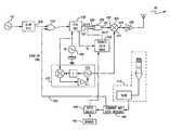
- the magnetic field generatorincludes an analog section that generates and FSK-modulates the non-propagating magnetic field, and a digital section that converts stored or incoming digital data into switch control signals.
- the switch control signalscontrollably switch capacitor components in circuit with a magnetic field coil, thereby modulating the resonant frequency of an inductor-capacitor (LC) tank circuit, to effect FSK-modulation of the magnetic field in accordance with the digital data.
- LCinductor-capacitor
- the magnetic field coilis small compared to the operating frequency and volumetric extent of its generated magnetic field, so that energy in the magnetic field is not propagated.
- a pumping switchis periodically operated in a fly-back manner, to provide a DC current boost to the magnetic field coil from its DC power supply, compensating for resistive losses in the tank circuit.
- Zero crossing points of the resonant frequency signalare supplied to a microcontroller which controls capacitor insertion switches of a multi-capacitor circuit, producing FSK modulation of the resonant magnetic field.
- tuning capacitorsmay be controllably switched in and out of the resonator tank circuit to determine optimum frequency matches for a desired FSK frequency pair.
- calibration-based ‘best match’ capacitorsare switchably coupled in parallel with a base capacitor, to precisely define a pair of resonant frequencies associated with the binary states of the digital data.
- An alternate pinger embodimenteliminates the multi-capacitor circuit and employs a microcontroller to generate and control pulse timing and duration used to pump the field coil.
- the receiver unitincludes LC tank detector circuit that includes a magnetic field-sensing coil in parallel with an associated capacitor.
- the LC tank circuitresonates at a frequency between the two FSK frequencies employed by the transmitter unit.
- the resonant detector circuitis coupled to a sense amplifier, which amplifies the voltage produced by the tank circuit for the desired receiver sensitivity and buffers the detected voltage to the level used by a digital receiver—demodulator.
- the digital receiveris referenced to a clock frequency that corresponds to the difference between the two frequencies of the selected FSK modulation pair.
- the digital receivercontains two signal buffer paths, that operate on alternate sample periods one-half the period of the received data symbol rate, so that at least one of the two buffer paths will not be sampling data during transitions in the received FSK frequency.
- the demodulated datais buffered, so that it may be clocked out to control circuitry in the tag transceiver.
- the augmented tag transceiverincludes an oscillator coupled to a variable pseudo random (PN) pulse generator.
- the variable PN generatoris normally operative to generate series of relatively low repetition rate randomly occurring ‘blink’, pulses that are coupled to a high speed PN spreading sequence generator. These blink pulses define when the tag randomly transmits or ‘blinks’.
- the PN generatoris also coupled to receive a control signal on from the magnetic field receiver.
- the tag's magnetic field sensing circuitryIn response to the tag's magnetic field sensing circuitry demodulating an immediate blink message, FSK-modulated onto the magnetic field generated by the magnetic field pinger, it may couple a blink rate override signal to the variable PN generator, which temporarily by-passes the pulse rate at which ‘blink’ pulses are produced by variable PN generator and generates a series of rapid pulses which are coupled to the high speed PN spreading sequence generator. This serves to alert the tracking system of the proximity of the tagged object to an ‘increased sensitivity’, region where the magnetic field generator is installed.
- the high speed PN spreading sequence generatorIn response to an enabling ‘blink’, pulse, the high speed PN spreading sequence generator generates a prescribed spreading sequence of PN chips.
- the PN spreading sequence generatoris driven at the RF frequency output of a crystal oscillator which provides a reference frequency for a phase locked loop to establish a prescribed output frequency (for example a frequency of 2.4 GHz, to comply with FCC licensing rules).
- the RF output of the PLLis coupled to a mixer the output of which is coupled to an RF power amplifier for transmission.
- the mixeris also coupled to the output of a spreading sequence modulation exclusive-OR gate, which is coupled to receive the PN spreading chip sequence generated by the high speed PN generator.
- the exclusive-OR gateis also coupled to receive data stored in a tag data storage memory as clocked out by the PN spreading sequence generator.
- the tag memorystores a multibit code representative of the identification of the tag, and additional parameter data, such as that provided by an associated sensor installed on or external to the tag.
- a data select logic circuitis coupled to receive data transmitted to the tag by the FSK-modulated magnetic field pinger, and demodulated by the magnetic field sensing circuit. When a magnetic field-modulated message from the magnetic field generator is detected by the tag's receiver, data in the decoded message is written into memory.
- the demodulatoralso couples a signal to enable the PN generator, so that the tag's transmitter will immediately generate a response RF burst, in the same manner as it randomly and repeatedly ‘blink’ a PN spreading sequence transmission containing its identification code and any parameter data stored in memory. In addition, it increases the output pulse rate of the tag's blink PN generator, so that the tag will blink at an increased rate, for a preset time duration as desired for tracking.
- FIG. 1diagrammatically illustrates the general architecture of a tagged object tracking and location system detailed in the U.S. Patents to Belcher et al, U.S. Pat. Nos. 5,920,287, and 5,995,046;
- FIG. 2is a diagrammatic plan view of a reduced complexity monitored environment in which a geolocation system of the type disclosed in the above-referenced U.S. Patents to Belcher et al, and shown FIG. 1 may be installed;
- FIG. 3is a diagrammatic elevation view of a portion of the monitored environment of FIG. 2 ;
- FIG. 4diagrammatically illustrates the magnetic field coupling of a magnetic field generator or pinger with a magnetic field sensor of a tag transceiver
- FIG. 5shows a first embodiment of a magnetic field generator or pinger
- FIG. 6shows an alternative embodiment of a magnetic field generator
- FIG. 7diagrammatically illustrates the configuration of a magnetic field receiver unit for use with the pingers of FIGS. 5 and 6 ;
- FIG. 8shows the manner in which a tag transceiver unit of the radio location and tracking system of the Belcher et al patents may be modified to incorporate a magnetic field receiver.
- the inventionresides primarily in a magnetic field-based augmentation to the geolocation system of the type described in the above-referenced Belcher et al Patents.
- the present inventioninvolves placing a relatively short range, magnetic field proximity-based tag-programming (or ‘pinger’) arrangement at a location of the monitored environment that is proximate to a region (such as a doorway) through which a tagged object may pass.
- This tag-programming pingeris configured to emit an AC magnetic field encoded with information, such as but not limited to programming information, data or a stimulus, that is coupled to and sensed by a magnetic field-responsive receiver in any tag passing through the region.
- the inventionis readily implemented as an arrangement of RF and magnetic field communication circuits and associated digital signal processing components and attendant supervisory control circuitry therefor, that controls the operations of such circuits and components.
- the configuration of such circuits components and the manner in which they interface with other communication system equipmenthave, accordingly, been illustrated in readily understandable block diagram format, depicting details that are pertinent to the present invention, so as not to obscure the present disclosure with details which will be readily apparent to those skilled in the art having the benefit of the description herein.
- the block diagram illustrationsare primarily intended to show the major components of a tag-based geolocation system in a convenient functional grouping, whereby the present invention may be more readily understood.
- FIG. 2is a diagrammatic plan view of a reduced complexity monitored environment 200 in which a geolocation system of the type disclosed in the above-referenced U.S. Patents to Belcher et al, U.S. Pat. Nos. 5,920,287, and 5,995,046, and described above with reference to FIG. 1 may be installed.
- the environment 200has a generally rectangular defined by four, rectangle-defining, perimeter walls 201 , 202 , 203 and 204 , and also having an interior wall 205 that subdivides the monitored environment 200 into two adjacent sections 211 and 212 .
- the interior wall 205is shown as having a doorway 206 that provides a passageway between sections 211 and 212 .
- each of the tags 16may be programmed to normally ‘blink’ an encoded RF burst at a relatively slow repetition rate.
- any tagged objectbe moved and pass through the doorway, it is desired to have immediate knowledge of that passage, as well as subsequent tracking of the movement of the object.
- the present inventionaugments the tagged object tracking system of FIG. 1 in two ways. First, it places one or more relatively short range, magnetic field proximity-based, tag-programming generators proximate to the region of interest—here a region 207 , shown in broken lines in the proximity of the doorway 206 . As shown in FIG. 2 and in the diagrammatic elevation view of FIG. 3 , a plurality of relatively reduced range magnetic field generators or (‘pingers’) 210 may be placed above and along sides of the doorway 206 , so as to ensure complete spatial coverage for the doorway and accommodate any orientation of the tagged objects passing through it.
- ‘pingers’relatively reduced range magnetic field generators or
- the pingermay also be configured in the form of a hand-held wand, similar to a bar code scanner, so as to provide the capability of programming a tag via a connection to a personal computer, portable data terminal, and the like, or by simply pulling a trigger on the wand.
- a magnetic field pingerDue to its relatively short coverage range, such a magnetic field pinger is especially suited for confined space applications, such as doorways, gates, and the like.
- the low frequency of the pinging electromagnetic fieldis capable of penetrating thin metals such as foils, where radio signals are totally blocked.
- the use of a short range pingermeans that a large number of pingers and tags may be used in a single facility without interfering with one another.
- the second augmentationinvolves modifying the transceiver architecture of a respective tag to incorporate a magnetic field sensor that will enable the tag to appropriately respond to the encoded AC magnetic field generated by pinger 220 .
- each of the magnetic field generator (pinger) and the tag-installed magnetic field sensormay be respectively configured as described in the above referenced '340 application.
- the magnetic field generator 210generates a non-propagating magnetic field 220 , which is modulated or encoded with prescribed information to be demodulated by receiver circuitry 230 , to which the output of a magnetic field sensing unit 240 of a respective tag 16 (that has come within the magnetic field sensing proximity of the generator 210 ) is coupled.
- the magnetic field generator 210is preferably operative to produce an AC magnetic field 220 that is modulated with frequency shift keyed (FSK) modulation signals representative of digital data to be transmitted to the tag.
- FSKfrequency shift keyed
- magnetic field generator 210may comprise an analog section 212 , which is configured to generate and FSK-modulate the non-propagating magnetic field, and a digital section 214 that is operative to convert stored data or an incoming digital data stream into control signals that controllably switch the resonant frequency of magnetic coil—capacitor components of the analog section 212 between first and second precisely calibrated or pre-tuned frequency values, and thereby effect FSK-modulation of the generated magnetic field in accordance with the digital data.
- the datamay be augmented by additional coding such as Manchester coding, and/or a cyclic redundancy check (CRC) sequence.
- CRCcyclic redundancy check
- the analog section 212includes a magnetic field coil 221 , to which a relatively large amplitude energizing current is supplied by a DC power supply or battery 223 is coupled to the field coil 221 by way of a ‘pumping’ switch 224 .
- the magnetic field coil 221is small compared to the operating frequency and the volumetric extent of the resonant magnetic field 220 produced thereby, so that the energy in the magnetic field that emanates from and surrounds the coil is not propagated, but is physically confined relatively close to the coil, as in a typical solenoid.
- the curving electromagnetic field generated by the pingersis virtually impossible to defeat by tag orientation. This serves to provide substantially strong coupling of the magnetic field with the sensing coil of a tag proximate thereto. (As pointed out above, distributing one or more such magnetic field generators around a region of interest (such as above and alongside a doorway) ensures complete coverage of the region.)
- a zero-crossing detector 225is coupled in parallel with a resonant (‘tank’ or ‘ringing’) circuit formed by the field coil 221 and one or more capacitors 231 of a capacitor circuit 233 , and serves to periodically close open the pumping switch 224 in a fly-back manner, to provide a DC current boost to the coil 221 from the battery, compensating for resistive losses in the ringing circuit.
- the pumping signal generated by the zero-crossing detector 225provides for switch closure at or near the point at which the resonating current signal in the tank circuit crosses zero.
- This pumping signalhas a duration for a small fraction of a cycle of the resonant frequency of the magnetic field, and may be optimized for the intended range of operation of the generated field and the size of the coil 221 .
- the zero-crossing points of the resonant frequencyare supplied to a supervisory microcontroller 232 , for control of capacitor insertion switches 226 of the capacitor circuit 233 and thereby FSK modulation of the resonant magnetic field.
- Selective closure of one or more of the switches 226 by the supervisory microcontroller 232 in accordance with respective binary states of the digital data streamplaces two or more capacitors 231 in parallel, thereby controllably tuning the resonant frequency of the encoded magnetic field.
- the clock reference employed by the microcontroller 232 to control the switches 224may use the coil 221 and one of the capacitors of the tank circuit, or a separate clock source, such as a crystal oscillator 234 .
- This separate clock sourceserves as a reference for the microcontroller 232 for measuring the resonant frequency established by the tank circuit at transmitter initialization and periodically thereafter. This ensures that the two resonant frequencies used for FSK modulation are within spec.
- small valued capacitorsmay be controllably switched in and out of the tank circuit to determine the optimum frequency matches for the desired frequency pair. Thereafter, during data transmission, these ‘best match’ capacitors are switchably employed to define the resonant frequencies associated with the binary states of the digital data.
- FIG. 6shows a reduced hardware complexity embodiment of the magnetic field generator 210 .
- microcontroller 232controls the pulse timing and duration used to pump the field coil 221 .
- This configurationeliminates some of the analog circuitry at the cost of requiring accurate, temperature-stable components in the resonant LC network, and may be preferred in small battery-operated and portable applications.
- a relatively low inductance, auxiliary coil 221 Ais transformer-coupled with the high inductance field coil 221 .
- the auxiliary coil 221 Ais coupled to the battery through the pumping switch 224 , which is controlled directly by the microcontroller 232 .
- the tank circuitis DC-isolated from the pumping switch, a relatively simple switch can be used.
- Each of the magnetic field generator configurations of FIGS. 5 and 6when employed in heavy industrial applications, benefits from a power control loop, to allow for correction of the magnetic field level, thereby maintaining communication performance, when the system is affected by the proximity of a large metallic body such as a passing automobile or forklift.
- the power source 223is adjusted appropriately by a control signal generated by monitoring the level of the voltage present in the resonant LC circuit.
- the power source 223may be controllably varied by means of an adjustable regulator 236 , wherein the detected resonant circuit voltage is fed back via a feed back link to the adjustment portion of the regulator, to form a closed control loop.
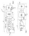
- FIG. 7diagrammatically illustrates the configuration of a magnetic field sensing unit 240 for a respective tag as comprising a comprising a resonant (LC tank) detector circuit 300 having a magnetic field-sensing coil 301 coupled in parallel with a capacitor 302 .
- the parameters of the tank circuit componentsare such that the tank circuit 300 resonates at a frequency between the two FSK frequencies employed by the FSK-modulating magnetic field generator 210 .
- the tank circuit 300may have a resonant frequency of 131 kHz.
- the resonant tank circuit 300is coupled to a sense amplifier 305 , which amplifies the voltage produced by the tank sensor circuit for the desired receiver sensitivity and buffers the detected voltage to the appropriate logic level for use by a digital receiver—demodulator 306 .
- the digital receiver—demodulator 306includes a digital receiver 310 , that is referenced to a crystal clock 312 .
- the receiver clockis set to a frequency that corresponds to the difference between the FSK frequencies of the selected modulation pair F 1 /F 2 .
- the receiver clockmay be set at 32.8 kHz. This reduced clock frequency serves maintains very low power consumption at low cost.
- the use of such a relatively low reference frequency in the receiverrequires a slower data rate, since one clock cycle of the receiver clock represents only 3.4-3.8 FSK clock cycles.
- the digital receiver 310may employ complementary buffer paths A/B that operate on alternate sample periods one-half the period of the received data spread code. This ensures that at least one of the two buffer paths will not be sampling data during transitions in the received FSK frequency.
- the digital demodulator 320contains a state machine that demodulates the data by comparing a received sequence of FSK tones with a predefined start-of-message sequence (corresponding to a start synchronization code).
- the start-of-message sequencemay comprise a plurality of successive samples at one FSK frequency or tone (such as three symbol periods at the higher of the two FSK tones), followed by a plurality of successive samples at the second FSK frequency (e.g., three symbol periods at the lower of the two FSK tones).
- the state machineUpon detecting this sequence, the state machine initializes the data demodulation circuitry, so that the data may be clocked out as it is detected and demodulated.
- data values of ‘1’ and ‘0’are represented by respectively difference sequences of the two FSK tones.
- a logical ‘one’may correspond to one symbol period at the higher FSK tone (147.5 KhZ) followed by one spreading chip period at the lower FSK tone (114.7 kHz);
- a logical ‘zero’may correspond to one symbol period at the lower FSK tone (114.7 kHz), followed by one symbol period at the higher FSK tone (147.5 KhZ).
- the demodulator's state machinemay detect the end of a message by comparing a received sequence of FSK tones with a predefined end-of-message sequence.
- the end-of-message sequencemay be complementary to the start-of-message sequence, described above.
- the receivermay employ a phase detector a quadrature phase shift circuit resonant at the center of the two FSK tones.
- This alternative embodimenteliminates the requirement for a large spectral separation between the tones, so as to allow a narrower receiver bandwidth with better sensitivity and reduced susceptibility to interference.
- the higher FSK tonemay be reduced to 127 KHz, while still using the efficient 32.8 KHz system clock.
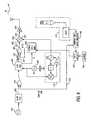
- FIG. 8shows the manner in which the circuit architecture of a tag transceiver (transmitter—transponder) unit employed in the radio location and tracking system of the type detailed in the above-referenced Belcher et al patents (such as that shown in FIG. 4 of U.S. Pat. No. 5,920,287) may be modified to incorporate an encoded magnetic field receiver, such as that disclosed in the '340 application and described above with reference to FIG. 7 .
- the augmented tag transceivercomprises an oscillator 401 , the output of which is coupled to a variable pseudo random (PN) pulse generator 402 .
- PNpseudo random
- the PN generator 402is normally operative to generate series of relatively low repetition rate (for example, from tens of seconds to several hours), randomly occurring ‘blink’ pulses that are coupled through an OR gate 404 to a high speed PN spreading sequence generator 406 . These blink pulses define when the tag randomly transmits or ‘blinks’ bursts of wideband (spread spectrum) RF energy to be detected by the tag transmission readers, in order to locate and identify the tag using time-of-arrival geometry processing of the identified first-to-arrive signals, as described above.
- the PN generator 402is also coupled to receive a control signal on line 403 from magnetic field sensing circuitry of the type shown in FIG. 7 , and depicted generally in broken lines 410 .
- the tag's magnetic field sensing circuitrydemodulating a blink rate reprogramming message, FSK-modulated onto the magnetic field generated by the magnetic field generator (pinger), it couples a blink rate change signal (e.g., changes the binary state of line 403 from its default, low blink rate representative level to a high blink rate logic level) to the variable PN generator 402 .
- a blink rate change signale.g., changes the binary state of line 403 from its default, low blink rate representative level to a high blink rate logic level
- Thisincreases the pulse rate at which ‘blink’ pulses are produced by generator and coupled through OR gate 404 to the high speed PN spreading sequence generator 406 .
- the tagblinks at an increased rate and thereby alert the tracking system of the proximity of the tagged object to an ‘increased sensitivity’ region where the magnetic field generator is installed.
- the high speed PN spreading sequence generator 406In response to an enabling ‘blink’ pulse, the high speed PN spreading sequence generator 406 generates a prescribed spreading sequence of PN chips.
- the PN spreading sequence generator 406is driven at the RF frequency output of a crystal oscillator 408 .
- This crystal oscillatorprovides a reference frequency for a phase locked loop (PLL) 412 , which establishes a prescribed output frequency (for example a frequency of 2.4 GHz, to comply with FCC licensing rules).
- PLLphase locked loop
- the RF output of PLL 412is coupled to a first input 421 of a mixer 423 , the output 424 of which is coupled to an RF power amplifier 426 .
- Mixer 423has a second input 425 coupled to the output 431 of a spreading sequence modulation exclusive-OR gate 433 .
- a first input 435 of the exclusive-OR gate 431is coupled to receive the PN spreading chip sequence generated by PN generator 406 .
- a second input 437 of exclusive-OR gate 431is coupled to receive the respective bits of data stored in a tag data storage memory 440 , which are clocked out by the PN spreading sequence generator 406 .
- the tag memory 440may comprise a relatively low power, electrically alterable CMOS memory circuit, which stores a multibit word or code representative of the identification of the tag.
- the tag memory 440may also store additional parameter data, such as that provided by an associated sensor (e.g., a temperature sensor) 442 installed on or external to the tag, and coupled thereto by way of a data select logic circuit 444 .
- the data select logic circuit 444is further coupled to receive data transmitted to the tag by the FSK-modulated magnetic field generator, described above, and demodulated by the magnetic field sensing circuit 410 . For this purpose the demodulated data is decoded by a command and data decoder 446 .
- the data select logic circuit 444may implemented in gate array logic and is operative to append any data it receives to that already stored in the tag memory 440 . It may also selectively couple sensor data to memory, so that the tag will send only previously stored data. It may also selectively filter or modify data output by the command and data decoder 446 .
- the data in the decoded messageis written into the tag memory 440 , via the data select logic circuit 444 .
- the command and data decoder 446also couples a signal through OR gate 404 to the enable input of the PN generator 406 , so that the tag's transmitter will immediately generate a response RF burst, in the same manner as it randomly and repeatedly ‘blinks’, a PN spreading sequence transmission containing its identification code and any parameter data stored in memory 440 , as described above.
- the desire to communicate with or controllably modify the operation of a tag whose object comes within a prescribed region (e.g., passes through a passageway) of a monitored environmentis readily accomplished in accordance with the present invention, by placing an arrangement of one or more relatively short range, magnetic field proximity-based, tag-programming ‘pingers’ at a respective location of the monitored environment that is proximate to the region through which a tag may pass.
- the pingermay be readily implemented and the tag transceiver augmented in accordance with the respective magnetic field generator and tag-installed magnetic field sensor architectures described in the above referenced '340 application.
- the magnetic field generatormay be installed on a fork-lift, so that a tagged item being moved by the fork-lift will receive the increased blink rate command. This will allow continuous tracking of a tagged item, as it is being moved by the fork-lift. After the fork-lift has transported and deposited the tagged item, and then leaves the proximity of the tagged item, the tag will again resume its previous slow blink rate, thus conserving battery life.
Landscapes
- Physics & Mathematics (AREA)
- Life Sciences & Earth Sciences (AREA)
- General Life Sciences & Earth Sciences (AREA)
- General Physics & Mathematics (AREA)
- Geophysics (AREA)
- Near-Field Transmission Systems (AREA)
Abstract
Description
Claims (20)
Priority Applications (5)
| Application Number | Priority Date | Filing Date | Title |
|---|---|---|---|
| US09/759,290US6853687B2 (en) | 2000-01-12 | 2001-01-11 | Proximity-based magnetic field generator for controlling operation of RF burst-transmitting tags of geolocation system |
| US09/800,079US6476719B2 (en) | 2000-03-07 | 2001-03-06 | Ultra-sensitive magnetic field receiver capable of operating in high noise environments |
| US09/818,276US6812839B1 (en) | 2000-03-27 | 2001-03-27 | Use of rotating magnetic field to enhance communication with RF burst-transmitting tags of object location system |
| AU2001251022AAU2001251022A1 (en) | 2000-03-27 | 2001-03-27 | Use of rotating magnetic field to enhance communication with rf burst-transmitting tags of object location system |
| PCT/US2001/009781WO2001074020A1 (en) | 2000-03-27 | 2001-03-27 | Use of rotating magnetic field to enhance communication with rf burst-transmitting tags of object location system |
Applications Claiming Priority (3)
| Application Number | Priority Date | Filing Date | Title |
|---|---|---|---|
| US17564200P | 2000-01-12 | 2000-01-12 | |
| US09/689,340US6349116B1 (en) | 1999-10-14 | 2000-10-12 | Data communication system harnessing frequency shift keyed magnetic field |
| US09/759,290US6853687B2 (en) | 2000-01-12 | 2001-01-11 | Proximity-based magnetic field generator for controlling operation of RF burst-transmitting tags of geolocation system |
Related Parent Applications (1)
| Application Number | Title | Priority Date | Filing Date |
|---|---|---|---|
| US09/689,340Continuation-In-PartUS6349116B1 (en) | 1999-10-14 | 2000-10-12 | Data communication system harnessing frequency shift keyed magnetic field |
Related Child Applications (2)
| Application Number | Title | Priority Date | Filing Date |
|---|---|---|---|
| US09/800,079Continuation-In-PartUS6476719B2 (en) | 2000-03-07 | 2001-03-06 | Ultra-sensitive magnetic field receiver capable of operating in high noise environments |
| US09/818,276Continuation-In-PartUS6812839B1 (en) | 2000-03-27 | 2001-03-27 | Use of rotating magnetic field to enhance communication with RF burst-transmitting tags of object location system |
Publications (2)
| Publication Number | Publication Date |
|---|---|
| US20020077710A1 US20020077710A1 (en) | 2002-06-20 |
| US6853687B2true US6853687B2 (en) | 2005-02-08 |
Family
ID=26871425
Family Applications (1)
| Application Number | Title | Priority Date | Filing Date |
|---|---|---|---|
| US09/759,290Expired - LifetimeUS6853687B2 (en) | 2000-01-12 | 2001-01-11 | Proximity-based magnetic field generator for controlling operation of RF burst-transmitting tags of geolocation system |
Country Status (1)
| Country | Link |
|---|---|
| US (1) | US6853687B2 (en) |
Cited By (28)
| Publication number | Priority date | Publication date | Assignee | Title |
|---|---|---|---|---|
| US20030091122A1 (en)* | 2001-09-26 | 2003-05-15 | Humphreys David A. | Data transfer using frequency notching of radio-frequency signals |
| US20060220851A1 (en)* | 2004-08-12 | 2006-10-05 | Wherenet Corp | System and method for tracking containers in grounded marine terminal operations |
| US20070010940A1 (en)* | 2005-07-05 | 2007-01-11 | Containertrac, Inc. | Automatic past error corrections for location and inventory tracking |
| US20070119927A1 (en)* | 2005-11-28 | 2007-05-31 | Wherenet Corp | Tag mounting device used for locating shipping containers and truck trailers |
| US20070182556A1 (en)* | 2006-01-31 | 2007-08-09 | Wherenet Corp | System and method for tracking assets within a monitored environment |
| US20070222674A1 (en)* | 2006-03-24 | 2007-09-27 | Containertrac, Inc. | Automated asset positioning for location and inventory tracking using multiple positioning techniques |
| US20070230424A1 (en)* | 2006-03-31 | 2007-10-04 | Wherenet Corp. | Wireless local area network receiver and associated method |
| US20070248180A1 (en)* | 2006-04-19 | 2007-10-25 | Wherenet Corp., Corporation Of The State Of California | Receiver for object locating and tracking systems and related methods |
| US20070280182A1 (en)* | 2006-04-26 | 2007-12-06 | Wherenet Corp. | Wireless local area network system and receiver adapted for use thereof and associated method |
| US20080130604A1 (en)* | 2006-12-05 | 2008-06-05 | Wherenet Corp. | Location system for wireless local area network (wlan) using rssi and time difference of arrival (tdoa) processing |
| US20080191937A1 (en)* | 2007-02-13 | 2008-08-14 | Wherenet Corp. | System and method for tracking vehicles and containers |
| US20080262885A1 (en)* | 2007-04-17 | 2008-10-23 | Wherenet Corp | Flow metering of vehicles using rtls tracking |
| US20080266131A1 (en)* | 2007-02-13 | 2008-10-30 | Wherenet Corp. | System, apparatus and method for locating and/or tracking assets |
| US20090303102A1 (en)* | 2008-04-26 | 2009-12-10 | Roke Manor Research Limited | Multilateration System and Method |
| US7916026B2 (en) | 2006-11-15 | 2011-03-29 | Zebra Enterprise Solutions Corp. | Real-time location system using tag interrogator and embedded or fixed tag transmitters |
| US20110211453A1 (en)* | 2006-04-26 | 2011-09-01 | Wherenet Corp | Method, Apparatus, and Computer Program Product for Wireless Signal Storage With Signal Recognition Detection Triggering |
| US8078103B2 (en) | 2005-10-31 | 2011-12-13 | Zih Corp. | Multi-element RFID coupler |
| US8922431B2 (en) | 2010-04-13 | 2014-12-30 | Becker Research And Development (Proprietary) Limited | Apparatus, a system and a method for collission avoidance |
| US9584252B1 (en) | 2015-09-25 | 2017-02-28 | Harris Corporation | Managed access system with mobile wireless device geolocation capability |
| US9681360B1 (en) | 2016-05-13 | 2017-06-13 | Harris Corporation | Managed access system that provides selective communications and registration of mobile wireless devices |
| US9736706B2 (en) | 2015-09-25 | 2017-08-15 | Harris Corporation | Managed access system with monitoring device to determine system operability |
| US9763095B2 (en) | 2015-09-25 | 2017-09-12 | Harris Corporation | Managed access system that determines authorized and unauthorized mobile wireless devices |
| US9769666B2 (en) | 2015-09-25 | 2017-09-19 | Harris Corporation | Managed access system with monitoring device to determine and change radio equipment |
| US9820150B2 (en) | 2015-09-25 | 2017-11-14 | Harris Corporation | Managed access system having filtered communications using network interface device |
| US10284559B2 (en) | 2016-05-13 | 2019-05-07 | Harris Corporation | Managed access system with security assessment equipment |
| US10405184B2 (en) | 2017-01-31 | 2019-09-03 | Harris Corporation | Mobile wireless device managed access system providing enhanced authentication features and related methods |
| US10802108B2 (en) | 2014-07-31 | 2020-10-13 | Symbol Technologies, Llc | Two pass detection technique for non-echo pulsed ranging |
| US12006152B2 (en) | 2021-01-22 | 2024-06-11 | Zebra Technologies Corporation | Methods and systems for managing temporary storage in warehouses |
Families Citing this family (14)
| Publication number | Priority date | Publication date | Assignee | Title |
|---|---|---|---|---|
| FR2826127B1 (en)* | 2001-06-19 | 2003-09-26 | Commissariat Energie Atomique | TELESURVEILLANCE INSTALLATION AND METHOD USING THE INSTALLATION |
| US7881409B2 (en)* | 2004-01-22 | 2011-02-01 | The Regents Of The University Of Michigan | Demodulator, chip and method for digitally demodulating an FSK signal |
| GB2457824B (en)* | 2006-09-19 | 2010-12-08 | Hydro Technologies Inc | Magnetic communication through metal barriers |
| GB2442798B (en)* | 2006-10-12 | 2011-03-23 | Cedardell Ltd | Security module |
| FI124722B (en)* | 2011-03-24 | 2014-12-31 | Nordic Id Oy | Device comprising a reader and method for controlling the function of the reader |
| EP2543813A1 (en)* | 2011-07-08 | 2013-01-09 | Nederlandse Organisatie voor toegepast -natuurwetenschappelijk onderzoek TNO | A telemetry system, a pipe and a method of transmitting information |
| US9654184B2 (en)* | 2012-07-20 | 2017-05-16 | WIPQTUS Inc. | Transmitter to receiver communication link in a wireless power system |
| US9730002B2 (en)* | 2014-04-10 | 2017-08-08 | Avago Technologies General Ip (Singapore) Pte. Ltd. | Mechanical enclosures for a communication device |
| JP6666649B2 (en)* | 2014-09-10 | 2020-03-18 | 孝浩 小林 | Magnetic communication system |
| US10523052B2 (en)* | 2014-09-16 | 2019-12-31 | Koninklijke Philips N.V. | Wireless inductive power transfer |
| RU2706348C1 (en)* | 2016-03-08 | 2019-11-18 | Конинклейке Филипс Н.В. | Wireless inductive power transfer |
| US10193720B1 (en)* | 2017-09-29 | 2019-01-29 | The United States Of America, As Represented By The Secretary Of The Army | Chaotically modulated communications with switched-capacitance resistance tuning |
| JP7088544B2 (en)* | 2018-06-22 | 2022-06-21 | 吉川工業株式会社 | Approach detection system |
| JP7026079B2 (en)* | 2019-06-17 | 2022-02-25 | 孝浩 小林 | Magnetic communication system |
Citations (12)
| Publication number | Priority date | Publication date | Assignee | Title |
|---|---|---|---|---|
| USRE32627E (en) | 1981-09-10 | 1988-03-22 | Sensormatic Electronics Corporation | Electrical surveillance apparatus with moveable antenna elements |
| US5103459A (en) | 1990-06-25 | 1992-04-07 | Qualcomm Incorporated | System and method for generating signal waveforms in a cdma cellular telephone system |
| US5432841A (en) | 1992-07-10 | 1995-07-11 | Rimer; Neil A. | System for locating and communicating with mobile vehicles |
| US5437057A (en) | 1992-12-03 | 1995-07-25 | Xerox Corporation | Wireless communications using near field coupling |
| US5481588A (en) | 1993-04-06 | 1996-01-02 | Alcatel N.V. | Test arrangements for radio telephone systems |
| US5485632A (en) | 1993-02-26 | 1996-01-16 | Motorola, Inc. | Method for initiating and determining simulcast transmission of a message |
| US5561701A (en) | 1992-01-10 | 1996-10-01 | Nec Corporation | Radio paging system having a plurality of transmitter stations |
| US5644108A (en) | 1994-07-18 | 1997-07-01 | Wacom Co., Ltd. | Position detection device utilizing electromagnetic induction |
| US5920261A (en)* | 1996-12-31 | 1999-07-06 | Design Vision Inc. | Methods and apparatus for tracking and displaying objects |
| US5920287A (en)* | 1997-01-21 | 1999-07-06 | Widata Corporation | Radio location system for precisely tracking objects by RF transceiver tags which randomly and repetitively emit wideband identification signals |
| US5995046A (en)* | 1998-01-30 | 1999-11-30 | Widata Corporation | Radio geo-location system with advanced first received wavefront arrival determination |
| US6476719B2 (en)* | 2000-03-07 | 2002-11-05 | Wherenet Corp. | Ultra-sensitive magnetic field receiver capable of operating in high noise environments |
- 2001
- 2001-01-11USUS09/759,290patent/US6853687B2/ennot_activeExpired - Lifetime
Patent Citations (13)
| Publication number | Priority date | Publication date | Assignee | Title |
|---|---|---|---|---|
| USRE32627E (en) | 1981-09-10 | 1988-03-22 | Sensormatic Electronics Corporation | Electrical surveillance apparatus with moveable antenna elements |
| US5103459A (en) | 1990-06-25 | 1992-04-07 | Qualcomm Incorporated | System and method for generating signal waveforms in a cdma cellular telephone system |
| US5103459B1 (en) | 1990-06-25 | 1999-07-06 | Qualcomm Inc | System and method for generating signal waveforms in a cdma cellular telephone system |
| US5561701A (en) | 1992-01-10 | 1996-10-01 | Nec Corporation | Radio paging system having a plurality of transmitter stations |
| US5432841A (en) | 1992-07-10 | 1995-07-11 | Rimer; Neil A. | System for locating and communicating with mobile vehicles |
| US5437057A (en) | 1992-12-03 | 1995-07-25 | Xerox Corporation | Wireless communications using near field coupling |
| US5485632A (en) | 1993-02-26 | 1996-01-16 | Motorola, Inc. | Method for initiating and determining simulcast transmission of a message |
| US5481588A (en) | 1993-04-06 | 1996-01-02 | Alcatel N.V. | Test arrangements for radio telephone systems |
| US5644108A (en) | 1994-07-18 | 1997-07-01 | Wacom Co., Ltd. | Position detection device utilizing electromagnetic induction |
| US5920261A (en)* | 1996-12-31 | 1999-07-06 | Design Vision Inc. | Methods and apparatus for tracking and displaying objects |
| US5920287A (en)* | 1997-01-21 | 1999-07-06 | Widata Corporation | Radio location system for precisely tracking objects by RF transceiver tags which randomly and repetitively emit wideband identification signals |
| US5995046A (en)* | 1998-01-30 | 1999-11-30 | Widata Corporation | Radio geo-location system with advanced first received wavefront arrival determination |
| US6476719B2 (en)* | 2000-03-07 | 2002-11-05 | Wherenet Corp. | Ultra-sensitive magnetic field receiver capable of operating in high noise environments |
Cited By (52)
| Publication number | Priority date | Publication date | Assignee | Title |
|---|---|---|---|---|
| US20030091122A1 (en)* | 2001-09-26 | 2003-05-15 | Humphreys David A. | Data transfer using frequency notching of radio-frequency signals |
| US7656963B2 (en) | 2001-09-26 | 2010-02-02 | General Atomics | Data transfer using frequency notching of radio-frequency signals |
| US7177368B2 (en)* | 2001-09-26 | 2007-02-13 | General Atomics | Data transfer using frequency notching of radio-frequency signals |
| US20060220851A1 (en)* | 2004-08-12 | 2006-10-05 | Wherenet Corp | System and method for tracking containers in grounded marine terminal operations |
| US7848881B2 (en) | 2005-07-05 | 2010-12-07 | Containertrac, Inc. | Automatic past error corrections for location and inventory tracking |
| US20070010940A1 (en)* | 2005-07-05 | 2007-01-11 | Containertrac, Inc. | Automatic past error corrections for location and inventory tracking |
| US8306474B2 (en) | 2005-10-31 | 2012-11-06 | Zih Corp. | Multi-element RFID coupler |
| US8078103B2 (en) | 2005-10-31 | 2011-12-13 | Zih Corp. | Multi-element RFID coupler |
| US9391675B2 (en) | 2005-10-31 | 2016-07-12 | Zih Corp. | Multi-element RFID coupler |
| US7475814B2 (en) | 2005-11-28 | 2009-01-13 | Wherenet Corp. | Tag mounting device used for locating shipping containers and truck trailers |
| US20070119927A1 (en)* | 2005-11-28 | 2007-05-31 | Wherenet Corp | Tag mounting device used for locating shipping containers and truck trailers |
| US20110163895A1 (en)* | 2006-01-31 | 2011-07-07 | Rado Rodrigo | System and method for tracking assets within a monitored environment |
| US7916023B2 (en) | 2006-01-31 | 2011-03-29 | Zebra Enterprise Solutions Corp. | System and method for tracking assets within a monitored environment |
| US20070182556A1 (en)* | 2006-01-31 | 2007-08-09 | Wherenet Corp | System and method for tracking assets within a monitored environment |
| US8842002B2 (en) | 2006-01-31 | 2014-09-23 | Zih Corp. | System and method for tracking assets within a monitored environment |
| US20070222674A1 (en)* | 2006-03-24 | 2007-09-27 | Containertrac, Inc. | Automated asset positioning for location and inventory tracking using multiple positioning techniques |
| US7646336B2 (en) | 2006-03-24 | 2010-01-12 | Containertrac, Inc. | Automated asset positioning for location and inventory tracking using multiple positioning techniques |
| US20070230424A1 (en)* | 2006-03-31 | 2007-10-04 | Wherenet Corp. | Wireless local area network receiver and associated method |
| US9699680B2 (en) | 2006-03-31 | 2017-07-04 | Zih Corp. | Wireless local area network receiver and associated method |
| US8768343B2 (en) | 2006-03-31 | 2014-07-01 | Zebra Enterprise Solutions Corp | Wireless local area network receiver and associated method |
| US20070248180A1 (en)* | 2006-04-19 | 2007-10-25 | Wherenet Corp., Corporation Of The State Of California | Receiver for object locating and tracking systems and related methods |
| US8265191B2 (en) | 2006-04-19 | 2012-09-11 | Zebra Enterprise Solutions Corp. | Receiver for object locating and tracking systems and related methods |
| US9362976B2 (en) | 2006-04-26 | 2016-06-07 | Zih Corp. | Wireless local area network system and receiver adapted for use thereof and associated method |
| US8892065B2 (en) | 2006-04-26 | 2014-11-18 | Zebra Enterprise Solutions Corp. | Method, apparatus, and computer program product for wireless signal storage with signal recognition detection triggering |
| US20070280182A1 (en)* | 2006-04-26 | 2007-12-06 | Wherenet Corp. | Wireless local area network system and receiver adapted for use thereof and associated method |
| US20110211453A1 (en)* | 2006-04-26 | 2011-09-01 | Wherenet Corp | Method, Apparatus, and Computer Program Product for Wireless Signal Storage With Signal Recognition Detection Triggering |
| US7916026B2 (en) | 2006-11-15 | 2011-03-29 | Zebra Enterprise Solutions Corp. | Real-time location system using tag interrogator and embedded or fixed tag transmitters |
| US20110148589A1 (en)* | 2006-11-15 | 2011-06-23 | Zebra Enterprise Solutions Corp. | Real-Time Location System Using Tag Interrogator and Embedded or Fixed Tag Transmitters |
| US7899006B2 (en) | 2006-12-05 | 2011-03-01 | Zebra Enterprise Solutions Corp. | Location system for wireless local area network (WLAN) using RSSI and time difference of arrival (TDOA) processing |
| WO2008070044A1 (en) | 2006-12-05 | 2008-06-12 | Wherenet Corp | Location system for wireless local area network (wlan) using rssi and time difference of arrival (tdoa) processing |
| US20080130604A1 (en)* | 2006-12-05 | 2008-06-05 | Wherenet Corp. | Location system for wireless local area network (wlan) using rssi and time difference of arrival (tdoa) processing |
| US20080266131A1 (en)* | 2007-02-13 | 2008-10-30 | Wherenet Corp. | System, apparatus and method for locating and/or tracking assets |
| US9880283B2 (en) | 2007-02-13 | 2018-01-30 | Zih Corp. | System, apparatus and method for locating and/or tracking assets |
| US7755541B2 (en) | 2007-02-13 | 2010-07-13 | Wherenet Corp. | System and method for tracking vehicles and containers |
| US20080191937A1 (en)* | 2007-02-13 | 2008-08-14 | Wherenet Corp. | System and method for tracking vehicles and containers |
| US20080262885A1 (en)* | 2007-04-17 | 2008-10-23 | Wherenet Corp | Flow metering of vehicles using rtls tracking |
| DE112008000709T5 (en) | 2007-04-17 | 2010-02-04 | Wherenet Corp., Santa Clara | Flow measurement of vehicles using RTLS tracking |
| US9747575B2 (en) | 2007-04-17 | 2017-08-29 | Zih Corp. | Flow metering of vehicles using RTLS tracking |
| US20090303102A1 (en)* | 2008-04-26 | 2009-12-10 | Roke Manor Research Limited | Multilateration System and Method |
| US8232913B2 (en) | 2008-04-26 | 2012-07-31 | Roke Manor Research Limited | Multilateration system and method |
| US8138967B2 (en)* | 2008-04-26 | 2012-03-20 | Roke Manor Research Limited | Multilateration system and method |
| US8922431B2 (en) | 2010-04-13 | 2014-12-30 | Becker Research And Development (Proprietary) Limited | Apparatus, a system and a method for collission avoidance |
| US10802108B2 (en) | 2014-07-31 | 2020-10-13 | Symbol Technologies, Llc | Two pass detection technique for non-echo pulsed ranging |
| US9769666B2 (en) | 2015-09-25 | 2017-09-19 | Harris Corporation | Managed access system with monitoring device to determine and change radio equipment |
| US9763095B2 (en) | 2015-09-25 | 2017-09-12 | Harris Corporation | Managed access system that determines authorized and unauthorized mobile wireless devices |
| US9584252B1 (en) | 2015-09-25 | 2017-02-28 | Harris Corporation | Managed access system with mobile wireless device geolocation capability |
| US9820150B2 (en) | 2015-09-25 | 2017-11-14 | Harris Corporation | Managed access system having filtered communications using network interface device |
| US9736706B2 (en) | 2015-09-25 | 2017-08-15 | Harris Corporation | Managed access system with monitoring device to determine system operability |
| US10284559B2 (en) | 2016-05-13 | 2019-05-07 | Harris Corporation | Managed access system with security assessment equipment |
| US9681360B1 (en) | 2016-05-13 | 2017-06-13 | Harris Corporation | Managed access system that provides selective communications and registration of mobile wireless devices |
| US10405184B2 (en) | 2017-01-31 | 2019-09-03 | Harris Corporation | Mobile wireless device managed access system providing enhanced authentication features and related methods |
| US12006152B2 (en) | 2021-01-22 | 2024-06-11 | Zebra Technologies Corporation | Methods and systems for managing temporary storage in warehouses |
Also Published As
| Publication number | Publication date |
|---|---|
| US20020077710A1 (en) | 2002-06-20 |
Similar Documents
| Publication | Publication Date | Title |
|---|---|---|
| US6853687B2 (en) | Proximity-based magnetic field generator for controlling operation of RF burst-transmitting tags of geolocation system | |
| US6812839B1 (en) | Use of rotating magnetic field to enhance communication with RF burst-transmitting tags of object location system | |
| US6476719B2 (en) | Ultra-sensitive magnetic field receiver capable of operating in high noise environments | |
| US7321290B2 (en) | Radio tag and system | |
| US6282407B1 (en) | Active electrostatic transceiver and communicating system | |
| JP4766437B2 (en) | Multi-mode tags and methods for making and using multi-mode tags | |
| US5680106A (en) | Multibit tag with stepwise variable frequencies | |
| US7023342B2 (en) | Continuous wave (CW)—fixed multiple frequency triggered, radio frequency identification (RFID) tag and system and method employing same | |
| US6650227B1 (en) | Reader for a radio frequency identification system having automatic tuning capability | |
| US7474215B2 (en) | Alarm systems, remote communication devices, and article security methods | |
| ES2338878T3 (en) | COMMUNICATION DEVICE FOR ESTABLISHING A DATA CONNECTION BETWEEN SMART DEVICES. | |
| US20140191044A1 (en) | Dual Use RFID/EAS Device | |
| US20100295682A1 (en) | Radio tag and system | |
| RU2400818C2 (en) | Eas reader detecting eas function in rfid device | |
| US7663489B2 (en) | Alarm systems, wireless alarm devices, and article security methods | |
| AU2007243363B2 (en) | Alarm systems, wireless alarm devices, and article security methods | |
| CA2403539A1 (en) | Electronic article surveillance and identification device, system, and method | |
| WO2005109329A1 (en) | Semi-passive radio frequency identification (rfid) tag with active beacon | |
| US20110163882A1 (en) | Passive Low Frequency Inductive Tagging | |
| US6349116B1 (en) | Data communication system harnessing frequency shift keyed magnetic field | |
| JPH0720237A (en) | Object position recognition system | |
| WO2001067043A9 (en) | Ultra-sensitive magnetic field receiver capable of operating in high noise environments | |
| WO2001074020A1 (en) | Use of rotating magnetic field to enhance communication with rf burst-transmitting tags of object location system | |
| WO2000016283A1 (en) | Generation of electrostatic voltage potentials for rfid/eas using piezoelectric crystals | |
| Vun et al. | Development of an embedded based rfid front end system |
Legal Events
| Date | Code | Title | Description |
|---|---|---|---|
| AS | Assignment | Owner name:WHERENET CORP, CALIFORNIA Free format text:ASSIGNMENT OF ASSIGNORS INTEREST;ASSIGNORS:HARRINGTON, TIMOTHY C.;HASH, RONALD J.;BELCHER, DONALD K.;REEL/FRAME:011785/0792;SIGNING DATES FROM 20010312 TO 20010319 | |
| AS | Assignment | Owner name:SILICON VALLEY BANK, CALIFORNIA Free format text:SECURITY AGREEMENT;ASSIGNOR:WHERENET CORP.;REEL/FRAME:014918/0646 Effective date:20030428 | |
| STCF | Information on status: patent grant | Free format text:PATENTED CASE | |
| AS | Assignment | Owner name:WHERENET CORPORATION, CALIFORNIA Free format text:RELEASE BY SECURED PARTY;ASSIGNOR:SILICON VALLEY BANK;REEL/FRAME:018866/0148 Effective date:20070129 | |
| AS | Assignment | Owner name:SILICON VALLEY BANK, CALIFORNIA Free format text:SECURITY INTERESTS RELEASE;ASSIGNOR:WHERENET CORP.;REEL/FRAME:018855/0734 Effective date:20070125 | |
| FEPP | Fee payment procedure | Free format text:PAYOR NUMBER ASSIGNED (ORIGINAL EVENT CODE: ASPN); ENTITY STATUS OF PATENT OWNER: LARGE ENTITY | |
| FPAY | Fee payment | Year of fee payment:4 | |
| AS | Assignment | Owner name:ZEBRA ENTERPRISE SOLUTIONS CORP., CALIFORNIA Free format text:CHANGE OF NAME;ASSIGNOR:WHERENET CORP.;REEL/FRAME:025217/0323 Effective date:20090713 | |
| FPAY | Fee payment | Year of fee payment:8 | |
| AS | Assignment | Owner name:MORGAN STANLEY SENIOR FUNDING, INC. AS THE COLLATERAL AGENT, MARYLAND Free format text:SECURITY AGREEMENT;ASSIGNORS:ZIH CORP.;LASER BAND, LLC;ZEBRA ENTERPRISE SOLUTIONS CORP.;AND OTHERS;REEL/FRAME:034114/0270 Effective date:20141027 Owner name:MORGAN STANLEY SENIOR FUNDING, INC. AS THE COLLATE Free format text:SECURITY AGREEMENT;ASSIGNORS:ZIH CORP.;LASER BAND, LLC;ZEBRA ENTERPRISE SOLUTIONS CORP.;AND OTHERS;REEL/FRAME:034114/0270 Effective date:20141027 | |
| AS | Assignment | Owner name:ZIH CORP., ILLINOIS Free format text:ASSIGNMENT OF ASSIGNORS INTEREST;ASSIGNOR:ZEBRA ENTERPRISE SOLUTIONS CORP.;REEL/FRAME:036503/0630 Effective date:20150828 | |
| AS | Assignment | Owner name:ZIH CORP., ILLINOIS Free format text:ASSIGNMENT OF ASSIGNORS INTEREST;ASSIGNOR:ZEBRA ENTERPRISE SOLUTIONS CORP.;REEL/FRAME:036552/0588 Effective date:20150828 | |
| FPAY | Fee payment | Year of fee payment:12 | |
| AS | Assignment | Owner name:JPMORGAN CHASE BANK, N.A., AS THE SUCCESSOR AGENT, NEW YORK Free format text:PATENT SECURITY INTEREST ASSIGNMENT AGREEMENT;ASSIGNOR:MORGAN STANLEY SENIOR FUNDING, INC., AS THE EXISTING AGENT;REEL/FRAME:044791/0842 Effective date:20170907 Owner name:JPMORGAN CHASE BANK, N.A., AS THE SUCCESSOR AGENT, Free format text:PATENT SECURITY INTEREST ASSIGNMENT AGREEMENT;ASSIGNOR:MORGAN STANLEY SENIOR FUNDING, INC., AS THE EXISTING AGENT;REEL/FRAME:044791/0842 Effective date:20170907 | |
| AS | Assignment | Owner name:ZEBRA TECHNOLOGIES CORPORATION, ILLINOIS Free format text:MERGER;ASSIGNOR:ZIH CORP.;REEL/FRAME:048884/0618 Effective date:20181220 | |
| AS | Assignment | Owner name:JPMORGAN CHASE BANK, N.A., AS COLLATERAL AGENT, NE Free format text:NOTICE OF TRANSFER OF SECURITY INTEREST IN PATENTS;ASSIGNOR:ZEBRA TECHNOLOGIES CORPORATION;REEL/FRAME:049675/0049 Effective date:20190701 Owner name:JPMORGAN CHASE BANK, N.A., AS COLLATERAL AGENT, NEW YORK Free format text:NOTICE OF TRANSFER OF SECURITY INTEREST IN PATENTS;ASSIGNOR:ZEBRA TECHNOLOGIES CORPORATION;REEL/FRAME:049675/0049 Effective date:20190701 | |
| AS | Assignment | Owner name:JPMORGAN CHASE BANK, N.A., NEW YORK Free format text:SECURITY INTEREST;ASSIGNORS:ZEBRA TECHNOLOGIES CORPORATION;LASER BAND, LLC;TEMPTIME CORPORATION;REEL/FRAME:053841/0212 Effective date:20200901 | |
| AS | Assignment | Owner name:LASER BAND, LLC, ILLINOIS Free format text:RELEASE OF SECURITY INTEREST - 364 - DAY;ASSIGNOR:JPMORGAN CHASE BANK, N.A.;REEL/FRAME:056036/0590 Effective date:20210225 Owner name:ZEBRA TECHNOLOGIES CORPORATION, ILLINOIS Free format text:RELEASE OF SECURITY INTEREST - 364 - DAY;ASSIGNOR:JPMORGAN CHASE BANK, N.A.;REEL/FRAME:056036/0590 Effective date:20210225 Owner name:TEMPTIME CORPORATION, NEW JERSEY Free format text:RELEASE OF SECURITY INTEREST - 364 - DAY;ASSIGNOR:JPMORGAN CHASE BANK, N.A.;REEL/FRAME:056036/0590 Effective date:20210225 |