US6853304B2 - Monitoring device - Google Patents
Monitoring deviceDownload PDFInfo
- Publication number
- US6853304B2 US6853304B2US10/139,634US13963402AUS6853304B2US 6853304 B2US6853304 B2US 6853304B2US 13963402 AUS13963402 AUS 13963402AUS 6853304 B2US6853304 B2US 6853304B2
- Authority
- US
- United States
- Prior art keywords
- sensor
- housing
- person
- wrist
- strap
- Prior art date
- Legal status (The legal status is an assumption and is not a legal conclusion. Google has not performed a legal analysis and makes no representation as to the accuracy of the status listed.)
- Expired - Lifetime, expires
Links
Images


Classifications
- G—PHYSICS
- G08—SIGNALLING
- G08B—SIGNALLING OR CALLING SYSTEMS; ORDER TELEGRAPHS; ALARM SYSTEMS
- G08B21/00—Alarms responsive to a single specified undesired or abnormal condition and not otherwise provided for
- G08B21/18—Status alarms
- G08B21/22—Status alarms responsive to presence or absence of persons
Definitions
- the present inventiongenerally relates to electronic monitoring systems and in particular to a monitoring device especially suitable for monitoring persons suffering from handicap dementia, down syndrome, autism, and other developmental problems.
- An electronic monitoring systemtypically comprises one or more portable transmitting devices, known as “tags”, attached to a monitored object, one or more local monitoring units for receiving signals from said tags, and optionally a central monitoring station where information from local monitoring units is collected and optionally further processed.
- a transmitting tagtypically broadcasts identification information and may further include additional information regarding activities or state of the monitored object.
- the portable tagis usually strapped around a limb of the person being monitored and typically includes various sensors for sensing tampering with the tag and other activities of the monitored person.
- dementia related diseasessuch as Alzheimer
- Dementiais a chronic or persistent disorder of behavior and higher intellectual function due to organic brain disease. It is marked by memory disorders, changes in personality, deterioration in personal care, impaired reasoning and disorientation. Although more abundant with aged people, various dementia related disorders also occur in young or middle age people. The most common cause of dementia is Alzheimer's disease. Other causes of dementia include successive strokes (vascular dementia), severe or repeated head injury, cardiac arrest, toxic ingestion and chronic infections of the central nervous system. Alzheimer disease is a progressive form of dementia, characterized by loss of short-term memory, deterioration in behavior and intellectual performance, confusion and slowness of thought. Dementia usually begins slowly and worsens over time at a progressive rate, which varies with different people.
- Alzheimer disease and other dementia disordersare disorientation in both time and space, which too often results in patients wandering away and losing their way back. Such incidents might put the patients in life-threatening situations. Consequently, dementia patients need to be under continuous monitoring supervision for their own safety. However, at all stages, and especially during early and intermediate stages, the balance between patients safety and independence is very important.
- an electronic wireless monitoring systemmay be a good solution for monitoring patients in need of personal care or who become disoriented or incapacitated (such as incapacitation of the higher cerebral function) or of need of nursing.
- a monitoring system for monitoring and supervising dementia patientsshould take into consideration the special behavior and sensitivities of this population.
- the tagshould assume the form of a very familiar object, which would not require from the patient any new learning or adaptation.
- the present inventionby providing a monitoring transmitting device, which has the appearance, dimensions and functioning of a regular wristwatch, reduces patient potential interference with the monitoring system and provides dementia patients and their caregivers safety, dignity and independence.
- the present inventionovercomes the disadvantages of the prior art by providing an electronic monitoring device having, in addition to a transmitting and monitoring capabilities, the appearance, dimensions and functionality of a common wristwatch.
- the deviceis used for monitoring, at a remote location, movements and optionally activities of a person, and is worn around a wrist of the person being monitored.
- the deviceis particularly suitable for monitoring patients suffering from dementia and other like or related disorders.
- the deviceis also suitable for patients showing symptoms of autism, mental retardation and other patients in need of personal care or who become disoriented or incapacitated.
- the deviceis suitable for patients with patients suffering from psychiatric disorders, such as schizophrenia.
- the devicecan be used for monitoring such patients at home or at care centers.
- the electronic monitoring device of the inventioncomprises: a housing having a front face and a back face; at least one strap connected to the housing for securing the device around the wrist of the person being monitored; tamper sensors for detecting cutting and removal of the device from the person's wrist and detecting any damage to the device while still attached to the wrist; an electronic circuitry enclosed within the housing, the circuitry includes a microprocessor and a memory device for receiving and processing data and a transmitter for periodically transmitting data to a remote location; and a time display, coupled to a clock mechanism, mounted in the housing so as to be displayed at the front face of the housing.
- the time displaycan be either analogue or digital.
- the tamper sensorfor detecting the removal of the device from the person's wrist, is an open-closure sensor detecting absence of electrical continuity.
- the tamper sensormay comprise of sensors which detect removal of the device by sensing body or sensors which detect any damage to the device while still attached to the wrist, and the like. The tamper sensor may provide indication that a body is near or that damage is being inflicted to the device.
- the deviceincludes an identification code stored in the memory device and carried by the signals periodically transmitted by the transmitter.
- the transmittercan be any transmitter suitable for wireless communication.
- the transmitteris a radio frequency transmitter and the like.
- the devicemay further comprise sensors for sensing activities and/or health state of the monitored person, including a movement sensor, a body temperature sensor, a pulse sensor, a blood pressure sensor and a blood oxygen sensor.
- the data collected by the at least one sensorcan be carried by the transmitted signals.
- the devicemay further comprise a receiver for receiving data from a remote location, a local monitoring unit or another watch. For example: receiving data via an Infra Red device, receiving audio data, receiving data via a radio frequency device and the like.
- FIG. 1illustrates a person wearing the monitoring transmitting watch of the present invention
- FIG. 2Ais a frontal perspective view of a monitoring watch in accordance with one embodiment of the present invention.
- FIG. 2Bis a backside perspective view of a monitoring watch of FIG. 2A ;
- FIGS. 2C and 2Dgive perspective frontal and backside views, respectively, of a disassembled monitoring watch in accordance with FIGS. A and B;
- FIGS. 3 , 3 A, 3 B and 3 Cillustrate a monitoring watch and assembly thereof in accordance with a second embodiment of the present invention
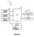
- FIG. 4is a block diagram of an electronic circuitry of a monitoring device in accordance with one embodiment of the present invention.
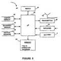
- FIG. 5is a block diagram of an electronic circuitry of a monitoring device in accordance with another embodiment of the present invention.
- the present inventionprovides a monitoring transmitting device to be worn around the wrist of a monitored person, especially suitable for patients who suffer from dementia related disorders, such as Alzheimer.
- the deviceis also suitable for patients showing symptoms of autism, mental retardation and other patients in need of personal care or who become disoriented or incapacitated.
- the deviceis suitable for patients with patients suffering from psychiatric disorders, such as schizophrenia.
- the devicecomprises a monitoring module including a transmitter for transmitting signals and a time display coupled to a clock mechanism for displaying the time of day, and optionally the date.
- the deviceis as simple to wear as wearing a wristwatch.
- the deviceis lightweight, waterproof, and is provided with tamper alerts, low battery indication and optionally with various sensors for sensing activities and medical parameters of the person being monitored.
- the deviceshould be: 1) rugged, so that temporary or accidental application or use of force does not damage it; 2) properly secured to the person, so it doesn't “fall off” or easily removed (but can be removed using reasonable force if and when required); 3) “tamper monitored” so that if and when it is damaged or is taken off, notification or indication is provided, and 4) familiar, comfortable and unobtrusive to the wearer.
- dementia patientsinclude reference to other patients showing symptoms of autism, mental retardation and other patients in need of personal care or who become disoriented or incapacitated, or to patients suffering from psychiatric disorders.
- FIG. 1illustrates a monitoring device 10 in accordance with the present invention, strapped around the wrist of a person 5 , in particular a patient, for monitoring movement and other activities of the person.
- the data detected by monitoring device 10is transmitted wirelessly to a local receiving monitoring unit 15 in the general area of the person being monitored.
- the unit 15may also be configured to transmit messages to device 10 .
- monitoring device 10has the appearance of a regular wristwatch having a time display 12 on the front face. Device 10 not only appears as a regular watch, but also functions as such, displaying the time of day, and optionally the date, of day. Device 10 facilitates best performance of a monitoring system.
- the device 10Being a very familiar object, device 10 does not evoke any negative emotions, which might cause the patient to attempt to remove or to tamper with the device. Also, device 10 does not draw any special attention from other people, which might embarrass or intimidate the patient. Therefore, the device allows the patient to live regular life as much as possible, keeping his self esteem and dignity, while at the same time allowing caregivers continuous monitoring of the patient. Furthermore, it is known that clocks and calendars in their immediate surrounding help to orient dementia patients by keeping a continuous track of time. Thus, having the monitoring device functioning as a clock imparts the device further beneficial effect in this respect as well.
- the time displaymay be either analog or digital.
- the devicemay further have a vibrator, buzzer or a speaker device for alerting the patient.
- the devicecan receive audio signals from a remote location in order to alert and notify the people present around the patient of the crises event.
- the devicemay also initiate preprogrammed audio warnings to the patient during the crisis situation.
- One crisis situationcan be an event whereby the patient has left a predetermined area or has tried to remove the device.
- FIGS. 2A to 2 Ddepict of a monitoring device 10 in accordance with one embodiment of the present invention.
- the deviceis having an analog time display 12 .
- device 10is having the appearance and dimensions of a common analog wristwatch.
- Device 10comprises a housing 20 and a pair of straps 16 and 17 , connected to opposite sides of housing 20 for strapping the device around the wrist.
- Housing 20comprises a hollow flat cylindrical body closed at one open face, hereinafter referred to as the frontal face, by a transparent window 19 and at the second open face, hereinafter referred to as the back face, by cover plate 21 .
- the body of the housingmay take various shapes and sizes depending on the specific design used at any given time. It may have for example cylindrical body or rectangle body.
- a time display 12is mounted inside watchcase 20 facing transparent window 19 . Also encased within housing 20 are a clock mechanism 35 and a monitoring transmitting module 30 , which includes an electronic circuitry responsible for the monitoring functioning of device 10 . Parts 19 , 20 and 21 , when assembled, form a hermetically closed waterproof case.
- the central part of housing 20is of a substantially cylindrical shape for accommodating a circular time display table, but it will be easily realized that watchcase 20 can assume any other shape such as a rectangle, a square, an oval, etc.
- Housing 20 and cover plate 21can be fabricated from any suitable metal or plastic material Housing 20 is provided with two extensions 23 extending from opposite sides thereof. Extensions 23 include connecting means for connecting straps 16 and 17 to housing 20 .
- members 23include a pin 24 which is first inserted into a corresponding loop 25 provided at one end of each of straps 16 and 17 . After mounting the strap on pin 24 , the two ends of pin 24 are inserted into recesses 27 provided on the opposite walls of extension 23 , as is best seen in FIG. 2 D.
- Straps 16 are 17are provided with means to allow the use of the device with different size persons (not shown). Such means can be, for example, a plurality of holes perforated along the length of one or both straps, through which a closure member can be inserted for fixing the effective length of the straps.
- Straps 16 are 17are preferably fabricated from flexible material such as rubber.
- straps 16 and 17are fabricated from a conductive material, preferably from an electrically conductive rubber or similar material, for example, a rubber doped with carbon particles.
- a metal connector 28(best seen in FIG. 2D ) couples recesses 27 and the inner side of housing 20 .
- straps 16 and 17can be made of a nonconductive flexible material wherein embedded electrical conductors are extending through the two straps such as to allow a closed electrical circuit when the free ends of the straps are engaged.
- Various fastening means for engaging the free ends of straps 16 and 17 for securing the device around the wristcan be employed.
- the strapsare made of conductive material, any engaging buckle or other known fastening means for engaging the free ends of the straps can be used, providing it ensures a fixed contact between the two straps for maintaining a closed electrical circuit.
- the electric circuit extending through the straps and housingshould be constructed such that it is open when the straps are disengaged or cut or tampered with and is closed upon their engagement.
- Such an arrangementis disclosed for example by U.S. Pat. No. 5,504,474, assigned to the same assignee of the present invention, where a separate closure member is deployed for closing the device both mechanically and electrically.
- the closure meansneed not be such as to provide a permanent irreversible closure, still it is desirable to design the closure in a way which is not easily being opened.
- monitoring devices designed mainly for law enforcementsuch as the device disclosed in the above cited U.S. Pat. No.
- the device of the present inventionaimed at monitoring patients, is not likely to be exposed to sophisticated and malicious tampering attempts.
- dementia and like patients, unaware of the role of the devicemight unintentionally take it off.
- the arrangement of the closureis such that both hands are required to open the closure.
- the strapmay contain optical fibers which continuously transmit signals, detecting a tamper when the sent signals do not reach the receiving end of the strap.
- An example of such closure meansis described below in conjunction with FIG. 3 . It should be emphasized that regardless of the closure means, an opening of the strap always results in opening the electrical circuit and consequently transmission of a corresponding tampering signal to the receiving monitoring unit. Additionally, or alternatively, monitoring device 10 may include any other known in the art tampering means.
- a removal sensorwhich senses body proximity might be employed.
- Housing 20is a hollow case accommodating a battery 26 , a monitoring transmitting module 30 and a clock module 35 .
- Clock module 35comprises a clock mechanism encased within case 36 and an analog time display plate 12 .
- the clock module 35is mounted inside watchcase 20 such that time display plate 12 is facing transparent window 19 .
- a crown 29coupled to the clock mechanism, protrudes from the side wall of housing 20 for allowing resetting the time and date.
- the monitoring transmitting module 30includes an electronic circuitry, preferably a printed circuitry board (PCB) which includes a transmitter, for broadcasting data to a receiver (not shown) remote location.
- the transmitter and corresponding receivermay be of any type suitable for wireless communication.
- the transmitteris a radio frequency (RF) transmitter while the receiver at the remote location is a radio frequency receiver.
- the transmittermay be an Infra Red (IR) transmitter transmitting to one or more IR detectors disposed at remote locations.
- Battery supply 52supplies power to module 30 and optionally to clock module 35 .
- clock module 35is powered by a separate battery encased within case 36 .
- Modules 30 and 35are designed such as to allow a compact packaging within housing 20 .
- FIG. 3depict yet another embodiment of the present monitoring device, in according to which the time display is digital.
- the main components of the device in accordance with this embodimentare similar to those of the analog embodiment described above.
- the device, generally designated 110comprises a housing 120 with two side extensions 123 for connecting straps 116 and 117 .
- Plate 121(best seen in FIG. 3B ) closes the open side of housing 120 in a manner which allows for hermetic and waterproof closure.
- a monitoring transmitting module 130comprising an electric circuitry 40 and powered by a battery (not shown).
- a digital clock 135having a liquid crystal time display 112 is mounted on the front face of housing 120 in an accepting recess 124 .
- Clock 135is provided with resetting pushbuttons (nor shown) for time resetting.
- straps 116 and 117are of the type disclosed in U.S. Pat. No. 5,504,474, having an electric circuitry extending through the straps and housing, when assembled together, which is electrically opened near the free end of strap 117 and terminates with external connectors 118 .
- Straps 116 and 117are connected to housing 120 by means of connecting members 128 having each a pair of holes 129 complementary to a pair of holes 126 at one end of each of the straps.
- extensions 123are provided with hollow cylindrical protrusions 127 provided with helical grooves on their inner surface, for accepting screws 131 .
- Extensions 123are further provided with a pair of connectors 141 which electrically connects housing 120 to the electrical conductors running through straps (not shown).
- strap 116is provided with holes 132 along its length and strap 117 is provided with a pair of holes 131 corresponding to the holes 132 .
- Straps 116 and 117are further provided with complementary ridges 133 and protrusions 134 , respectively, for enhancing immobilization of the straps with respect to each other.
- a closure membercomprising of two separate parts, 150 and 155 , is provided for closing device 10 around a person wrist both mechanically and electrically. However, as explained above, unlike the closure member disclosed in U.S. Pat. No.
- the mechanical locking provided by the closure means of the present inventionis preferably reversible such as to allow unfastening the device by caregivers.
- the base closure part 150is provided with two protrusions 153 , each terminating with a flexible tongue 154
- the cover closure member 155is provided with two complementary openings 158 .
- Protrusions 153 and openings 158are located so as to correspond to each other, and are spaced so as to correspond to pair of holes 131 of strap 117 and to holes 132 of strap 117 .
- the deviceis fastened around a wrist by inserting protrusions 153 through pair of holes 131 in strap member 117 and through a suitable pair of holes in strap member 116 , such that the straps overlap, then tongues 154 are forced through openings 158 of cover closure part 155 . In their relaxed position, tongues 154 slide into a narrow portion of opening 158 , thus providing mechanical locking which can be opened only by relatively complex operation.
- side walls 151 and 156 of parts 150 and 155can be shaped to have complementary shaped protrusion 152 and recess 157 for providing snapping locking-in-place means.
- cover closure part 155further includes means (not shown) for electrically connecting the external connectors 118 such as for example the conductive element described in U.S. Pat. No. 5,504,474.
- the closure means described in conjunction with FIG. 3is only an example and that many other closure means can be used without departing from the scope of the present invention.
- base part 150can be permanently fixed or being an integral part of strap member 117 .
- Electronic circuitry 40includes an electronic data microprocessor 50 for receiving and processing data, and a transmitter 60 for receiving, processing and transmitting via antenna 65 , data regarding the activity of the person to which device 10 is attached. Also included and coupled to microprocessor 50 is a memory device 55 for storing the tag identification code and the operation program for controlling the tag's operation.
- the data input to microprocessor 50includes data from at least one tamper sensor 42 for detecting cutting or removal of the device from the patient's wrist. In one embodiment of the present invention at least two tamper sensors 42 provide data input to microprocessor 50 .
- the first tamper sensormay be an open-closure sensor detecting the opening of the electrical circuit running through device 10 when the device is properly secured around the wrist of the monitored person, as explained above, the second tamper sensor may be a body sensor sensing body proximity as for example the short range transmitter-receiver couple disclosed in U.S. Pat. No. 5,504,474.
- the electronic circuitryfurther includes a movement sensor ( 44 ) for sensing motion of the person, and might include other sensors ( 46 ) as well. Sensors 46 can be incorporated into various physical parts of device 10 .
- sensors 46may include sensors for providing information about the medical condition of the monitored person, such as body temperature sensor, pulse sensor, blood pressure sensor, blood-oxygen sensor, etc.
- Microprocessor 50is programmed to activate the various sensing means to take readings at predetermined time intervals, to process said readings and to activate transmitter 60 to broadcast signals at predetermined time intervals and at predetermined length and intensity of the signal.
- the transmitted signalsmay carry the tag identification code and other data regarding the activities or state of the monitored person in accordance with the sensors input.
- the microprocessorcan be programmed with regard to various parameters in order to meet the requirements specific to the subject to whom the tag is attached. Thus, parameters such as sampling intervals, data transmission intervals, monitored time periods, permitted and barred locations, etc., can be selected according to specific needs.
- the tagmay also be programmed to change the time pattern of sampling and broadcasting when specific circumstances are detected by the sensing means.
- the tagmay, upon occurrence of a predetermined event, issue an alarm signal and increase or decrease the testing rate.
- a predetermined eventcan be an event involving the device operation, for example an attempt to remove the tag, low battery, failure of an electronic component or other component of device 10 , or can be an event involving the medical condition or the activities of the monitored person. For example, a temperature above or below predetermined values, lack of motion for a predetermined period of time, etc.
- FIG. 5depicts another embodiment of an electronic circuitry in which the monitoring unit further includes a receiver 70 for receiving data from remote location or a similar close by device.
- device 10can be controlled by data received from a remote location. For example, upon reception of a certain data in a local monitoring device, caregivers might decide to change certain parameters in the operation program of the device, such as frequency and intensity of transmitted signals.
- clock module 35is coupled to microprocessor 50 such as to allow time synchronization between microprocessor 50 and watch 35 and to allow remote time resetting of watch 35 .
- the monitoring device of the present inventioncan be used with a local monitoring system, with an area monitoring system comprising a plurality of monitoring receiving units, or with a combination thereof.
- a local monitoring systemtypically comprises of one local monitoring unit dedicated to a specific transmitting device.
- the local monitoring unitmay report to a central monitoring station or, alternatively, may be an independent station where data is processed for further action.
- a local monitoring unitis usually employed for supervising a single patient at home.
- An area monitoring systemtypically comprises a network of receivers, which cover a restricted or a pre-defined area in which a plurality of tag carriers are moving.
- dementia patientsuch a system may be employed in a nursing home, a hospital, an assisted living center and the like.
Landscapes
- Business, Economics & Management (AREA)
- Emergency Management (AREA)
- Physics & Mathematics (AREA)
- General Physics & Mathematics (AREA)
- Measuring And Recording Apparatus For Diagnosis (AREA)
Abstract
Description
Claims (23)
Priority Applications (1)
| Application Number | Priority Date | Filing Date | Title |
|---|---|---|---|
| US10/139,634US6853304B2 (en) | 2002-05-07 | 2002-05-07 | Monitoring device |
Applications Claiming Priority (1)
| Application Number | Priority Date | Filing Date | Title |
|---|---|---|---|
| US10/139,634US6853304B2 (en) | 2002-05-07 | 2002-05-07 | Monitoring device |
Publications (2)
| Publication Number | Publication Date |
|---|---|
| US20030210149A1 US20030210149A1 (en) | 2003-11-13 |
| US6853304B2true US6853304B2 (en) | 2005-02-08 |
Family
ID=29399344
Family Applications (1)
| Application Number | Title | Priority Date | Filing Date |
|---|---|---|---|
| US10/139,634Expired - LifetimeUS6853304B2 (en) | 2002-05-07 | 2002-05-07 | Monitoring device |
Country Status (1)
| Country | Link |
|---|---|
| US (1) | US6853304B2 (en) |
Cited By (41)
| Publication number | Priority date | Publication date | Assignee | Title |
|---|---|---|---|---|
| US20040183684A1 (en)* | 2003-03-19 | 2004-09-23 | Callaway James J. | Wireless patient ambulation motion detector and second call system |
| US20050052264A1 (en)* | 2002-01-30 | 2005-03-10 | Kabushiki Kaisha Bridgestone | Measured value output device, measured value monitor, current value output device, and current monitor |
| US20050068172A1 (en)* | 2003-09-29 | 2005-03-31 | King Deborah L. | Parental alert and child tracking device |
| US20050184870A1 (en)* | 2004-02-25 | 2005-08-25 | Dmatek, Ltd. | Method and apparatus for portable transmitting devices |
| US20050231366A1 (en)* | 2004-04-15 | 2005-10-20 | Mchugh Michael J | System and method for monitoring location of an object |
| US20060163349A1 (en)* | 2004-09-30 | 2006-07-27 | W5 Networks, Inc. | Wireless systems suitable for retail automation and promotion |
| US20060187045A1 (en)* | 2005-01-26 | 2006-08-24 | Rf Technologies, Inc. | Mobile locator system and method with wander management |
| US20070123754A1 (en)* | 2005-11-29 | 2007-05-31 | Cuddihy Paul E | Non-encumbering, substantially continuous patient daily activity data measurement for indication of patient condition change for access by remote caregiver |
| US20090138636A1 (en)* | 2007-09-07 | 2009-05-28 | Nike, Inc. | Wearable device assembly having athletic functionality |
| US20090264714A1 (en)* | 2006-05-18 | 2009-10-22 | Chang-An Chou | Non-invasive vital sign monitoring method, apparatus and system |
| US20090317051A1 (en)* | 2008-06-18 | 2009-12-24 | Millington Daniel K | Mobile Timestamp Systems and Methods of Use |
| US20100076337A1 (en)* | 2008-09-25 | 2010-03-25 | Nellcor Puritan Bennett Llc | Medical Sensor And Technique For Using The Same |
| US20100222073A1 (en)* | 2005-04-06 | 2010-09-02 | Omnilink Systems, Inc. | System and method for tracking, monitoring, collecting, reporting and communicating with the movement of individuals |
| US7809420B2 (en) | 2003-06-25 | 2010-10-05 | Nellcor Puritan Bennett Llc | Hat-based oximeter sensor |
| US7822453B2 (en) | 2002-10-01 | 2010-10-26 | Nellcor Puritan Bennett Llc | Forehead sensor placement |
| US20100315237A1 (en)* | 2009-06-10 | 2010-12-16 | Xiao Hui Yang | Eas tag for irregular objects |
| US20110053666A1 (en)* | 2009-08-27 | 2011-03-03 | Jaehyuk Kang | Mobile terminal |
| US8364220B2 (en) | 2008-09-25 | 2013-01-29 | Covidien Lp | Medical sensor and technique for using the same |
| US8410926B1 (en) | 2010-05-07 | 2013-04-02 | Rf Technologies, Inc. | Alarm for security tag |
| US8412297B2 (en) | 2003-10-01 | 2013-04-02 | Covidien Lp | Forehead sensor placement |
| US8515515B2 (en) | 2009-03-25 | 2013-08-20 | Covidien Lp | Medical sensor with compressible light barrier and technique for using the same |
| US8560557B1 (en) | 2011-12-14 | 2013-10-15 | Corrisoft, LLC | Method and system of progress monitoring |
| US8682356B2 (en) | 2011-12-22 | 2014-03-25 | Earthsweep Llc | Method and system of electronic monitoring |
| US8736447B2 (en) | 2011-12-20 | 2014-05-27 | Techip International Limited | Tamper-resistant monitoring systems and methods |
| US8781548B2 (en) | 2009-03-31 | 2014-07-15 | Covidien Lp | Medical sensor with flexible components and technique for using the same |
| US8862152B1 (en) | 2012-11-02 | 2014-10-14 | Alcohol Monitoring Systems, Inc. | Two-piece system and method for electronic management of offenders based on real-time risk profiles |
| US20150123766A1 (en)* | 2013-11-01 | 2015-05-07 | Jerry St. John | Escalating biometric identification |
| US9064391B2 (en) | 2011-12-20 | 2015-06-23 | Techip International Limited | Tamper-alert resistant bands for human limbs and associated monitoring systems and methods |
| WO2016044197A1 (en) | 2014-09-15 | 2016-03-24 | 3M Innovative Properties Company | Impairment detection |
| WO2016044199A1 (en) | 2014-09-15 | 2016-03-24 | 3M Innovative Properties Company | Impairment detection with biological considerations |
| WO2016044198A1 (en) | 2014-09-15 | 2016-03-24 | 3M Innovative Properties Company | Impairment detection with environmental considerations |
| US9311804B2 (en) | 2014-04-11 | 2016-04-12 | Hill-Rom Services, Inc. | Patient-need prediction system |
| US9460612B2 (en) | 2014-05-01 | 2016-10-04 | Techip International Limited | Tamper-alert and tamper-resistant band |
| US9521513B2 (en) | 2014-10-21 | 2016-12-13 | Earthsweep Llc | Method and system of zone suspension in electronic monitoring |
| US10231664B2 (en) | 2016-05-26 | 2019-03-19 | Raghav Ganesh | Method and apparatus to predict, report, and prevent episodes of emotional and physical responses to physiological and environmental conditions |
| US10395160B2 (en)* | 2015-04-13 | 2019-08-27 | Mysphera, S.L. | Identifier device |
| US10912501B2 (en) | 2008-07-03 | 2021-02-09 | Masimo Corporation | User-worn device for noninvasively measuring a physiological parameter of a user |
| US11545263B2 (en) | 2005-03-01 | 2023-01-03 | Cercacor Laboratories, Inc. | Multiple wavelength sensor emitters |
| US11638532B2 (en) | 2008-07-03 | 2023-05-02 | Masimo Corporation | User-worn device for noninvasively measuring a physiological parameter of a user |
| US12114974B2 (en) | 2020-01-13 | 2024-10-15 | Masimo Corporation | Wearable device with physiological parameters monitoring |
| US12336796B2 (en) | 2021-07-13 | 2025-06-24 | Masimo Corporation | Wearable device with physiological parameters monitoring |
Families Citing this family (27)
| Publication number | Priority date | Publication date | Assignee | Title |
|---|---|---|---|---|
| GB2415072B (en)* | 2004-06-07 | 2008-06-11 | Dmatek Ltd | A monitoring and tracking network |
| US7438216B2 (en)* | 2005-05-10 | 2008-10-21 | Siemens Medical Solutions Usa, Inc. | Medical information access and processing system |
| US7764167B2 (en)* | 2006-01-18 | 2010-07-27 | British Telecommunications Plc | Monitoring movement of an entity in an environment |
| US9563919B2 (en) | 2007-02-02 | 2017-02-07 | Hartford Fire Insurance Company | Safety evaluation and feedback system and method |
| US8358214B2 (en)* | 2007-02-02 | 2013-01-22 | Hartford Fire Insurance Company | Systems and methods for sensor-enhanced health evaluation |
| US8638228B2 (en) | 2007-02-02 | 2014-01-28 | Hartford Fire Insurance Company | Systems and methods for sensor-enhanced recovery evaluation |
| US7930927B2 (en)* | 2007-03-06 | 2011-04-26 | Bi Incorporated | Transdermal portable alcohol monitor and methods for using such |
| US20080266116A1 (en)* | 2007-04-25 | 2008-10-30 | Hyatt Dequincy A | Tracking and monitoring system |
| FR2929738B1 (en)* | 2008-04-04 | 2011-01-28 | Arjowiggins Licensing Sas | DOCUMENT COMPRISING AN INTEGRATED MICROCIRCUIT DEVICE AND METHOD FOR DETECTING THE INTEGRITY WITH THE PHYSICAL INTEGRITY OF THE DOCUMENT |
| US8493219B2 (en)* | 2008-11-14 | 2013-07-23 | Bi Incorporated | Systems and methods for adaptive monitoring and tracking of a target having a learning period |
| US20100177599A1 (en)* | 2009-01-11 | 2010-07-15 | Yang Pan | Determining location and survivability of a trapped person under a disaster situation by use of a wirst wearable device |
| US8657744B2 (en) | 2009-03-23 | 2014-02-25 | Bi Incorporated | Systems and methods for transdermal secretion detection |
| US8629776B2 (en)* | 2009-12-03 | 2014-01-14 | Bi Incorporated | Systems and methods for disrupting criminal activity |
| US9355548B2 (en) | 2009-12-03 | 2016-05-31 | Bi Incorporated | Systems and methods for contact avoidance |
| US8576065B2 (en)* | 2009-12-03 | 2013-11-05 | Bi Incorporated | Systems and methods for variable collision avoidance |
| CN102385786B (en)* | 2011-07-08 | 2014-07-02 | 沈磊 | Anti-removing wrist strap |
| GB2495294A (en)* | 2011-10-04 | 2013-04-10 | Retrieva Ltd | Welfare monitoring and tracking device |
| GB2518190B (en)* | 2013-09-12 | 2018-06-06 | Buddi Ltd | Tag including a thermo-chromic optical fibre |
| US9591913B2 (en)* | 2013-11-15 | 2017-03-14 | Jwin Electronics Corp. | Protection case |
| US20150254967A1 (en)* | 2014-03-04 | 2015-09-10 | Dequincy A. Hyatt | Tracking and monitoring system |
| US9575466B1 (en) | 2014-09-03 | 2017-02-21 | Fossil Group, Inc. | Sensor-enabled fashion timepiece |
| JP6172351B1 (en)* | 2016-07-05 | 2017-08-02 | オムロンヘルスケア株式会社 | Sphygmomanometer |
| EP3361276A1 (en) | 2017-02-14 | 2018-08-15 | Koninklijke Philips N.V. | A bridge member for a magnetic resonance examination system |
| US10650663B2 (en)* | 2018-01-01 | 2020-05-12 | Bi Incorporated | Systems and methods for multi-device restriction zone maintenance |
| US11627618B2 (en) | 2020-04-06 | 2023-04-11 | T-Mobile Usa, Inc. | Network-based RSI/PRACH parameter planning and neighbor creation |
| US11701007B2 (en) | 2020-08-28 | 2023-07-18 | Bi Incorporated | Systems and methods for biometric tamper detection |
| US11665507B2 (en) | 2020-09-15 | 2023-05-30 | Bi Incorporated | Systems and methods for intercept directing in a monitoring system |
Citations (6)
| Publication number | Priority date | Publication date | Assignee | Title |
|---|---|---|---|---|
| US5621384A (en)* | 1993-07-26 | 1997-04-15 | K And M Electronics, Inc. | Infrared communicating device |
| US5828306A (en)* | 1996-04-15 | 1998-10-27 | Curran; Brendan Joseph | Location detector and monitor and method of using the same |
| US5831535A (en)* | 1997-07-24 | 1998-11-03 | Elmo-Tech Ltd. | Electronic monitoring device and monitoring system including same |
| US5841352A (en)* | 1997-06-18 | 1998-11-24 | Prakash; Sushil | Child monitor |
| US5883576A (en)* | 1998-01-14 | 1999-03-16 | De La Huerga; Carlos | Identification bracelet with electronics information |
| US6166639A (en)* | 1999-03-12 | 2000-12-26 | Advanced Marketing Systems Corporation | Personal emergency response system |
- 2002
- 2002-05-07USUS10/139,634patent/US6853304B2/ennot_activeExpired - Lifetime
Patent Citations (6)
| Publication number | Priority date | Publication date | Assignee | Title |
|---|---|---|---|---|
| US5621384A (en)* | 1993-07-26 | 1997-04-15 | K And M Electronics, Inc. | Infrared communicating device |
| US5828306A (en)* | 1996-04-15 | 1998-10-27 | Curran; Brendan Joseph | Location detector and monitor and method of using the same |
| US5841352A (en)* | 1997-06-18 | 1998-11-24 | Prakash; Sushil | Child monitor |
| US5831535A (en)* | 1997-07-24 | 1998-11-03 | Elmo-Tech Ltd. | Electronic monitoring device and monitoring system including same |
| US5883576A (en)* | 1998-01-14 | 1999-03-16 | De La Huerga; Carlos | Identification bracelet with electronics information |
| US6166639A (en)* | 1999-03-12 | 2000-12-26 | Advanced Marketing Systems Corporation | Personal emergency response system |
Cited By (85)
| Publication number | Priority date | Publication date | Assignee | Title |
|---|---|---|---|---|
| US20050052264A1 (en)* | 2002-01-30 | 2005-03-10 | Kabushiki Kaisha Bridgestone | Measured value output device, measured value monitor, current value output device, and current monitor |
| US6987387B2 (en)* | 2002-01-30 | 2006-01-17 | Kabushiki Kaisha Bridgestone | Measurement value output device, measurement value monitoring device, current value output device and current monitoring device |
| US7822453B2 (en) | 2002-10-01 | 2010-10-26 | Nellcor Puritan Bennett Llc | Forehead sensor placement |
| US20110009723A1 (en)* | 2002-10-01 | 2011-01-13 | Nellcor Puritan Bennett Llc | Forehead sensor placement |
| US8452367B2 (en) | 2002-10-01 | 2013-05-28 | Covidien Lp | Forehead sensor placement |
| US7899509B2 (en) | 2002-10-01 | 2011-03-01 | Nellcor Puritan Bennett Llc | Forehead sensor placement |
| US7071820B2 (en)* | 2003-03-19 | 2006-07-04 | Callaway James J | Wireless patient ambulation motion detector and second call system |
| US20040183684A1 (en)* | 2003-03-19 | 2004-09-23 | Callaway James J. | Wireless patient ambulation motion detector and second call system |
| US7877127B2 (en) | 2003-06-25 | 2011-01-25 | Nellcor Puritan Bennett Llc | Hat-based oximeter sensor |
| US7813779B2 (en) | 2003-06-25 | 2010-10-12 | Nellcor Puritan Bennett Llc | Hat-based oximeter sensor |
| US7809420B2 (en) | 2003-06-25 | 2010-10-05 | Nellcor Puritan Bennett Llc | Hat-based oximeter sensor |
| US7979102B2 (en) | 2003-06-25 | 2011-07-12 | Nellcor Puritan Bennett Llc | Hat-based oximeter sensor |
| US7877126B2 (en) | 2003-06-25 | 2011-01-25 | Nellcor Puritan Bennett Llc | Hat-based oximeter sensor |
| US20050068172A1 (en)* | 2003-09-29 | 2005-03-31 | King Deborah L. | Parental alert and child tracking device |
| US8412297B2 (en) | 2003-10-01 | 2013-04-02 | Covidien Lp | Forehead sensor placement |
| US7064670B2 (en)* | 2004-02-25 | 2006-06-20 | Dmatek, Ltd. | Method and apparatus for portable transmitting devices |
| WO2005079150A3 (en)* | 2004-02-25 | 2006-02-02 | Dmatek Ltd | Method and apparatus for portable transmitting devices |
| US20050184870A1 (en)* | 2004-02-25 | 2005-08-25 | Dmatek, Ltd. | Method and apparatus for portable transmitting devices |
| US20050231366A1 (en)* | 2004-04-15 | 2005-10-20 | Mchugh Michael J | System and method for monitoring location of an object |
| US7084764B2 (en)* | 2004-04-15 | 2006-08-01 | Secure Care Products, Inc. | System and method for monitoring location of an object |
| US20060163349A1 (en)* | 2004-09-30 | 2006-07-27 | W5 Networks, Inc. | Wireless systems suitable for retail automation and promotion |
| US7365645B2 (en) | 2005-01-26 | 2008-04-29 | Rf Technologies, Inc. | Mobile locator system and method with wander management |
| US20060187045A1 (en)* | 2005-01-26 | 2006-08-24 | Rf Technologies, Inc. | Mobile locator system and method with wander management |
| US11545263B2 (en) | 2005-03-01 | 2023-01-03 | Cercacor Laboratories, Inc. | Multiple wavelength sensor emitters |
| US12230393B2 (en) | 2005-03-01 | 2025-02-18 | Willow Laboratories, Inc. | Multiple wavelength sensor emitters |
| US20100222073A1 (en)* | 2005-04-06 | 2010-09-02 | Omnilink Systems, Inc. | System and method for tracking, monitoring, collecting, reporting and communicating with the movement of individuals |
| US8831627B2 (en)* | 2005-04-06 | 2014-09-09 | Omnilink Systems, Inc. | System and method for tracking, monitoring, collecting, reporting and communicating with the movement of individuals |
| US20070123754A1 (en)* | 2005-11-29 | 2007-05-31 | Cuddihy Paul E | Non-encumbering, substantially continuous patient daily activity data measurement for indication of patient condition change for access by remote caregiver |
| US20090264714A1 (en)* | 2006-05-18 | 2009-10-22 | Chang-An Chou | Non-invasive vital sign monitoring method, apparatus and system |
| US20090138636A1 (en)* | 2007-09-07 | 2009-05-28 | Nike, Inc. | Wearable device assembly having athletic functionality |
| US20090143689A1 (en)* | 2007-09-07 | 2009-06-04 | Nike, Inc. | Wearable device assembly having athletic functionality |
| US8088043B2 (en)* | 2007-09-07 | 2012-01-03 | Nike, Inc. | Wearable device assembly having athletic functionality |
| US20090139764A1 (en)* | 2007-09-07 | 2009-06-04 | Nike,Inc. | Wearable device assembly having athletic functionality |
| US8469862B2 (en) | 2007-09-07 | 2013-06-25 | Nike, Inc. | Wearable device assembly having athletic functionality |
| US8370549B2 (en) | 2007-09-07 | 2013-02-05 | Nike, Inc. | Wearable device assembly having athletic functionality |
| US20090163322A1 (en)* | 2007-09-07 | 2009-06-25 | Nike, Inc. | Wearable device assembly having athletic functionality |
| US8408436B2 (en) | 2007-09-07 | 2013-04-02 | Nike, Inc. | Wearable device assembly having athletic functionality |
| US20090317051A1 (en)* | 2008-06-18 | 2009-12-24 | Millington Daniel K | Mobile Timestamp Systems and Methods of Use |
| US11638532B2 (en) | 2008-07-03 | 2023-05-02 | Masimo Corporation | User-worn device for noninvasively measuring a physiological parameter of a user |
| US11484229B2 (en) | 2008-07-03 | 2022-11-01 | Masimo Corporation | User-worn device for noninvasively measuring a physiological parameter of a user |
| US10912500B2 (en) | 2008-07-03 | 2021-02-09 | Masimo Corporation | Multi-stream data collection system for noninvasive measurement of blood constituents |
| US10912502B2 (en) | 2008-07-03 | 2021-02-09 | Masimo Corporation | User-worn device for noninvasively measuring a physiological parameter of a user |
| US12023139B1 (en) | 2008-07-03 | 2024-07-02 | Masimo Corporation | User-worn device for noninvasively measuring a physiological parameter of a user |
| US10945648B2 (en) | 2008-07-03 | 2021-03-16 | Masimo Corporation | User-worn device for noninvasively measuring a physiological parameter of a user |
| US11426103B2 (en) | 2008-07-03 | 2022-08-30 | Masimo Corporation | Multi-stream data collection system for noninvasive measurement of blood constituents |
| US11751773B2 (en) | 2008-07-03 | 2023-09-12 | Masimo Corporation | Emitter arrangement for physiological measurements |
| US11647914B2 (en) | 2008-07-03 | 2023-05-16 | Masimo Corporation | User-worn device for noninvasively measuring a physiological parameter of a user |
| US12036009B1 (en) | 2008-07-03 | 2024-07-16 | Masimo Corporation | User-worn device for noninvasively measuring a physiological parameter of a user |
| US11484230B2 (en) | 2008-07-03 | 2022-11-01 | Masimo Corporation | User-worn device for noninvasively measuring a physiological parameter of a user |
| US11642036B2 (en) | 2008-07-03 | 2023-05-09 | Masimo Corporation | User-worn device for noninvasively measuring a physiological parameter of a user |
| US11642037B2 (en) | 2008-07-03 | 2023-05-09 | Masimo Corporation | User-worn device for noninvasively measuring a physiological parameter of a user |
| US10912501B2 (en) | 2008-07-03 | 2021-02-09 | Masimo Corporation | User-worn device for noninvasively measuring a physiological parameter of a user |
| US20100076337A1 (en)* | 2008-09-25 | 2010-03-25 | Nellcor Puritan Bennett Llc | Medical Sensor And Technique For Using The Same |
| US8257274B2 (en) | 2008-09-25 | 2012-09-04 | Nellcor Puritan Bennett Llc | Medical sensor and technique for using the same |
| US8364220B2 (en) | 2008-09-25 | 2013-01-29 | Covidien Lp | Medical sensor and technique for using the same |
| US8515515B2 (en) | 2009-03-25 | 2013-08-20 | Covidien Lp | Medical sensor with compressible light barrier and technique for using the same |
| US8781548B2 (en) | 2009-03-31 | 2014-07-15 | Covidien Lp | Medical sensor with flexible components and technique for using the same |
| US20100315237A1 (en)* | 2009-06-10 | 2010-12-16 | Xiao Hui Yang | Eas tag for irregular objects |
| US8665095B2 (en)* | 2009-06-10 | 2014-03-04 | Wg Security Products | EAS tag for irregular objects |
| US8620395B2 (en)* | 2009-08-27 | 2013-12-31 | Lg Electronics Inc. | Mobile terminal |
| US20110053666A1 (en)* | 2009-08-27 | 2011-03-03 | Jaehyuk Kang | Mobile terminal |
| US8410926B1 (en) | 2010-05-07 | 2013-04-02 | Rf Technologies, Inc. | Alarm for security tag |
| US8560557B1 (en) | 2011-12-14 | 2013-10-15 | Corrisoft, LLC | Method and system of progress monitoring |
| US9240084B2 (en) | 2011-12-20 | 2016-01-19 | Techip International Limited | Elevator system preventing unauthorized use |
| US8736447B2 (en) | 2011-12-20 | 2014-05-27 | Techip International Limited | Tamper-resistant monitoring systems and methods |
| US9240119B2 (en) | 2011-12-20 | 2016-01-19 | Techip International Limited | Tamper-alert resistant bands for human limbs and associated monitoring systems and methods |
| US9064391B2 (en) | 2011-12-20 | 2015-06-23 | Techip International Limited | Tamper-alert resistant bands for human limbs and associated monitoring systems and methods |
| US8682356B2 (en) | 2011-12-22 | 2014-03-25 | Earthsweep Llc | Method and system of electronic monitoring |
| US8862152B1 (en) | 2012-11-02 | 2014-10-14 | Alcohol Monitoring Systems, Inc. | Two-piece system and method for electronic management of offenders based on real-time risk profiles |
| US20150123766A1 (en)* | 2013-11-01 | 2015-05-07 | Jerry St. John | Escalating biometric identification |
| US9311804B2 (en) | 2014-04-11 | 2016-04-12 | Hill-Rom Services, Inc. | Patient-need prediction system |
| US10172522B2 (en) | 2014-04-11 | 2019-01-08 | Hill-Rom Services, Inc. | Patient-need prediction system |
| US9763576B2 (en) | 2014-04-11 | 2017-09-19 | Hill-Rom Services, Inc. | Patient-need prediction system |
| US9460612B2 (en) | 2014-05-01 | 2016-10-04 | Techip International Limited | Tamper-alert and tamper-resistant band |
| WO2016044199A1 (en) | 2014-09-15 | 2016-03-24 | 3M Innovative Properties Company | Impairment detection with biological considerations |
| WO2016044197A1 (en) | 2014-09-15 | 2016-03-24 | 3M Innovative Properties Company | Impairment detection |
| US11324421B2 (en) | 2014-09-15 | 2022-05-10 | 3M Innovative Properties Company | Impairment detection with environmental considerations |
| US12089925B2 (en) | 2014-09-15 | 2024-09-17 | Attenti Electronic Monitoring Ltd. | Impairment detection |
| WO2016044198A1 (en) | 2014-09-15 | 2016-03-24 | 3M Innovative Properties Company | Impairment detection with environmental considerations |
| US12390126B2 (en) | 2014-09-15 | 2025-08-19 | Attenti Electronic Monitoring Ltd. | Impairment detection with biological considerations |
| US9521513B2 (en) | 2014-10-21 | 2016-12-13 | Earthsweep Llc | Method and system of zone suspension in electronic monitoring |
| US10395160B2 (en)* | 2015-04-13 | 2019-08-27 | Mysphera, S.L. | Identifier device |
| US10231664B2 (en) | 2016-05-26 | 2019-03-19 | Raghav Ganesh | Method and apparatus to predict, report, and prevent episodes of emotional and physical responses to physiological and environmental conditions |
| US12114974B2 (en) | 2020-01-13 | 2024-10-15 | Masimo Corporation | Wearable device with physiological parameters monitoring |
| US12336796B2 (en) | 2021-07-13 | 2025-06-24 | Masimo Corporation | Wearable device with physiological parameters monitoring |
Also Published As
| Publication number | Publication date |
|---|---|
| US20030210149A1 (en) | 2003-11-13 |
Similar Documents
| Publication | Publication Date | Title |
|---|---|---|
| US6853304B2 (en) | Monitoring device | |
| US9460262B2 (en) | Detecting and responding to sentinel events | |
| US6238354B1 (en) | Temperature monitoring assembly | |
| US5512879A (en) | Apparatus to prevent infant kidnappings and mixups | |
| KR101354625B1 (en) | Remote protection and surveillance system | |
| US6611783B2 (en) | Attitude indicator and activity monitoring device | |
| US20070038155A1 (en) | Attitude Indicator And Activity Monitoring Device | |
| US20020097155A1 (en) | Combination breathing monitor alarm and audio baby alarm | |
| US20040010390A1 (en) | Attitude indicator and activity monitoring device | |
| GB2505981A (en) | Tracking arrangement comprising wearable transmitter and locator units | |
| US20040080421A1 (en) | Monitoring and alert system | |
| US20080101160A1 (en) | Med Alert Watch | |
| US20100211080A1 (en) | Umbiliguard | |
| US20130182382A1 (en) | Tamper-alert resistant bands for human limbs and associated monitoring systems and methods | |
| US20110109461A1 (en) | Tamper detection system for use with personal monitoring devices | |
| SG182687A1 (en) | Portable eeg monitor system with wireless communication | |
| IL125488A (en) | Electronic monitoring device | |
| CN205485346U (en) | Electron supervision wrist -watch | |
| US10729211B2 (en) | Wristband locking mechanism, wristband, wearable electronic device and method of securing an article to a person | |
| WO2006134359A1 (en) | Seizure detection apparatus | |
| US20220398914A1 (en) | Wearable Device and System for Tracking and Sharing Vital Signs and Location of User | |
| KR102596008B1 (en) | Smart wristband for inpatient monitoring | |
| US20180276976A1 (en) | Personal safety device | |
| CN207516755U (en) | It is a kind of to carry health management system arranged smart phone wrist-watch | |
| US11183044B1 (en) | Wearable band providing location presence and fall detection |
Legal Events
| Date | Code | Title | Description |
|---|---|---|---|
| AS | Assignment | Owner name:DMATEK LTD., ISRAEL Free format text:ASSIGNMENT OF ASSIGNORS INTEREST;ASSIGNORS:REISMAN, YOAV;GALPERIN, NATAN;GEMER, GIL;AND OTHERS;REEL/FRAME:013199/0573;SIGNING DATES FROM 20020728 TO 20020730 | |
| STCF | Information on status: patent grant | Free format text:PATENTED CASE | |
| FEPP | Fee payment procedure | Free format text:PAYOR NUMBER ASSIGNED (ORIGINAL EVENT CODE: ASPN); ENTITY STATUS OF PATENT OWNER: LARGE ENTITY | |
| FPAY | Fee payment | Year of fee payment:4 | |
| AS | Assignment | Owner name:SILICON VALLEY BANK, AS ADMINISTRATIVE AGENT, CALI Free format text:SECURITY AGREEMENT;ASSIGNORS:DMATEK LTD.;PRO TECH MONITORING, INC.;ELMO-TECH LTD.;REEL/FRAME:023419/0828 Effective date:20091021 Owner name:SILICON VALLEY BANK, AS ADMINISTRATIVE AGENT,CALIF Free format text:SECURITY AGREEMENT;ASSIGNORS:DMATEK LTD.;PRO TECH MONITORING, INC.;ELMO-TECH LTD.;REEL/FRAME:023419/0828 Effective date:20091021 | |
| AS | Assignment | Owner name:ATTENTI LTD., ISRAEL Free format text:CHANGE OF NAME;ASSIGNOR:DMATEK, LTD.;REEL/FRAME:025799/0574 Effective date:20100217 | |
| AS | Assignment | Owner name:SILICON VALLEY BANK, CALIFORNIA Free format text:RELEASE BY SECURED PARTY;ASSIGNORS:DMATEK LTD.;PRO TECH MONITORING, INC.;ELMO TECH LTD.;REEL/FRAME:025879/0609 Effective date:20101020 | |
| AS | Assignment | Owner name:3M ATTENTI LTD., ISRAEL Free format text:CHANGE OF NAME;ASSIGNOR:ATTENTI LTD.;REEL/FRAME:026609/0702 Effective date:20110505 | |
| FEPP | Fee payment procedure | Free format text:PAT HOLDER NO LONGER CLAIMS SMALL ENTITY STATUS, ENTITY STATUS SET TO UNDISCOUNTED (ORIGINAL EVENT CODE: STOL); ENTITY STATUS OF PATENT OWNER: LARGE ENTITY | |
| REFU | Refund | Free format text:REFUND - PAYMENT OF MAINTENANCE FEE, 8TH YR, SMALL ENTITY (ORIGINAL EVENT CODE: R2552); ENTITY STATUS OF PATENT OWNER: LARGE ENTITY | |
| FPAY | Fee payment | Year of fee payment:8 | |
| FPAY | Fee payment | Year of fee payment:12 | |
| AS | Assignment | Owner name:DMATEK LTD., ISRAEL Free format text:CORRECTIVE ASSIGNMENT TO CORRECT THE ASSIGNOR AND ASSIGNEE DATA WERE INADVERTENTLY TRANSPOSED PREVIOUSLY RECORDED ON REEL 023419 FRAME 0828. ASSIGNOR(S) HEREBY CONFIRMS THE SECURITY AGREEMENT;ASSIGNOR:SILICON VALLEY BANK;REEL/FRAME:042522/0518 Effective date:20101020 Owner name:PRO-TECH MONITORING, FLORIDA Free format text:CORRECTIVE ASSIGNMENT TO CORRECT THE ASSIGNOR AND ASSIGNEE DATA WERE INADVERTENTLY TRANSPOSED PREVIOUSLY RECORDED ON REEL 023419 FRAME 0828. ASSIGNOR(S) HEREBY CONFIRMS THE SECURITY AGREEMENT;ASSIGNOR:SILICON VALLEY BANK;REEL/FRAME:042522/0518 Effective date:20101020 Owner name:ELMO TECH LTD., ISRAEL Free format text:CORRECTIVE ASSIGNMENT TO CORRECT THE ASSIGNOR AND ASSIGNEE DATA WERE INADVERTENTLY TRANSPOSED PREVIOUSLY RECORDED ON REEL 023419 FRAME 0828. ASSIGNOR(S) HEREBY CONFIRMS THE SECURITY AGREEMENT;ASSIGNOR:SILICON VALLEY BANK;REEL/FRAME:042522/0518 Effective date:20101020 | |
| AS | Assignment | Owner name:ATTENTI EM LTD, ISRAEL Free format text:CHANGE OF NAME;ASSIGNOR:3M ATTENTI LTD;REEL/FRAME:059846/0926 Effective date:20171026 | |
| AS | Assignment | Owner name:ATTENTI ELECTRONIC MONITORING LTD., ISRAEL Free format text:ASSIGNMENT OF ASSIGNORS INTEREST;ASSIGNOR:ATTENTI EM LTD;REEL/FRAME:062544/0486 Effective date:20221231 |