US6853174B1 - Selective high-side and low-side current sensing in switching power supplies - Google Patents
Selective high-side and low-side current sensing in switching power suppliesDownload PDFInfo
- Publication number
- US6853174B1 US6853174B1US10/639,066US63906603AUS6853174B1US 6853174 B1US6853174 B1US 6853174B1US 63906603 AUS63906603 AUS 63906603AUS 6853174 B1US6853174 B1US 6853174B1
- Authority
- US
- United States
- Prior art keywords
- switch
- voltage
- duty cycle
- current
- switching regulator
- Prior art date
- Legal status (The legal status is an assumption and is not a legal conclusion. Google has not performed a legal analysis and makes no representation as to the accuracy of the status listed.)
- Expired - Lifetime, expires
Links
- 238000001514detection methodMethods0.000claimsabstractdescription43
- 230000004044responseEffects0.000claimsabstractdescription11
- 230000001105regulatory effectEffects0.000claimsdescription26
- 230000007423decreaseEffects0.000claimsdescription17
- 239000003990capacitorSubstances0.000claimsdescription12
- 238000012544monitoring processMethods0.000claimsdescription11
- 238000000034methodMethods0.000claimsdescription10
- 230000003247decreasing effectEffects0.000claimsdescription4
- 238000001914filtrationMethods0.000claims1
- 230000009977dual effectEffects0.000abstractdescription3
- 238000010586diagramMethods0.000description14
- 238000005259measurementMethods0.000description6
- 230000007704transitionEffects0.000description5
- 230000001276controlling effectEffects0.000description4
- 238000004146energy storageMethods0.000description3
- 230000033228biological regulationEffects0.000description2
- 244000145845chatteringSpecies0.000description2
- 238000013461designMethods0.000description2
- 230000000630rising effectEffects0.000description2
- 238000012546transferMethods0.000description2
- 230000001052transient effectEffects0.000description2
- 206010035148PlagueDiseases0.000description1
- 241000607479Yersinia pestisSpecies0.000description1
- 238000013459approachMethods0.000description1
- 230000003139buffering effectEffects0.000description1
- 238000007796conventional methodMethods0.000description1
- 230000008878couplingEffects0.000description1
- 238000010168coupling processMethods0.000description1
- 238000005859coupling reactionMethods0.000description1
- 238000005516engineering processMethods0.000description1
- 238000010348incorporationMethods0.000description1
- 238000012986modificationMethods0.000description1
- 230000004048modificationEffects0.000description1
- 238000009877renderingMethods0.000description1
- 230000006641stabilisationEffects0.000description1
- 238000011105stabilizationMethods0.000description1
- 230000001360synchronised effectEffects0.000description1
- 230000001960triggered effectEffects0.000description1
Images


Classifications
- H—ELECTRICITY
- H02—GENERATION; CONVERSION OR DISTRIBUTION OF ELECTRIC POWER
- H02M—APPARATUS FOR CONVERSION BETWEEN AC AND AC, BETWEEN AC AND DC, OR BETWEEN DC AND DC, AND FOR USE WITH MAINS OR SIMILAR POWER SUPPLY SYSTEMS; CONVERSION OF DC OR AC INPUT POWER INTO SURGE OUTPUT POWER; CONTROL OR REGULATION THEREOF
- H02M3/00—Conversion of DC power input into DC power output
- H02M3/02—Conversion of DC power input into DC power output without intermediate conversion into AC
- H02M3/04—Conversion of DC power input into DC power output without intermediate conversion into AC by static converters
- H02M3/10—Conversion of DC power input into DC power output without intermediate conversion into AC by static converters using discharge tubes with control electrode or semiconductor devices with control electrode
- H02M3/145—Conversion of DC power input into DC power output without intermediate conversion into AC by static converters using discharge tubes with control electrode or semiconductor devices with control electrode using devices of a triode or transistor type requiring continuous application of a control signal
- H02M3/155—Conversion of DC power input into DC power output without intermediate conversion into AC by static converters using discharge tubes with control electrode or semiconductor devices with control electrode using devices of a triode or transistor type requiring continuous application of a control signal using semiconductor devices only
- H02M3/156—Conversion of DC power input into DC power output without intermediate conversion into AC by static converters using discharge tubes with control electrode or semiconductor devices with control electrode using devices of a triode or transistor type requiring continuous application of a control signal using semiconductor devices only with automatic control of output voltage or current, e.g. switching regulators
- H02M3/158—Conversion of DC power input into DC power output without intermediate conversion into AC by static converters using discharge tubes with control electrode or semiconductor devices with control electrode using devices of a triode or transistor type requiring continuous application of a control signal using semiconductor devices only with automatic control of output voltage or current, e.g. switching regulators including plural semiconductor devices as final control devices for a single load
- H02M3/1588—Conversion of DC power input into DC power output without intermediate conversion into AC by static converters using discharge tubes with control electrode or semiconductor devices with control electrode using devices of a triode or transistor type requiring continuous application of a control signal using semiconductor devices only with automatic control of output voltage or current, e.g. switching regulators including plural semiconductor devices as final control devices for a single load comprising at least one synchronous rectifier element
- H—ELECTRICITY
- H02—GENERATION; CONVERSION OR DISTRIBUTION OF ELECTRIC POWER
- H02M—APPARATUS FOR CONVERSION BETWEEN AC AND AC, BETWEEN AC AND DC, OR BETWEEN DC AND DC, AND FOR USE WITH MAINS OR SIMILAR POWER SUPPLY SYSTEMS; CONVERSION OF DC OR AC INPUT POWER INTO SURGE OUTPUT POWER; CONTROL OR REGULATION THEREOF
- H02M1/00—Details of apparatus for conversion
- H02M1/0003—Details of control, feedback or regulation circuits
- H02M1/0009—Devices or circuits for detecting current in a converter
- Y—GENERAL TAGGING OF NEW TECHNOLOGICAL DEVELOPMENTS; GENERAL TAGGING OF CROSS-SECTIONAL TECHNOLOGIES SPANNING OVER SEVERAL SECTIONS OF THE IPC; TECHNICAL SUBJECTS COVERED BY FORMER USPC CROSS-REFERENCE ART COLLECTIONS [XRACs] AND DIGESTS
- Y02—TECHNOLOGIES OR APPLICATIONS FOR MITIGATION OR ADAPTATION AGAINST CLIMATE CHANGE
- Y02B—CLIMATE CHANGE MITIGATION TECHNOLOGIES RELATED TO BUILDINGS, e.g. HOUSING, HOUSE APPLIANCES OR RELATED END-USER APPLICATIONS
- Y02B70/00—Technologies for an efficient end-user side electric power management and consumption
- Y02B70/10—Technologies improving the efficiency by using switched-mode power supplies [SMPS], i.e. efficient power electronics conversion e.g. power factor correction or reduction of losses in power supplies or efficient standby modes
Definitions
- the inventionrelates to switching power supplies or switching regulators and, in particular, to a switching regulator employing selective current sensing to assert either peak or valley control.
- a switching regulatoralso referred to as a switching mode power supply, provides power supply function through low loss components such as capacitors, inductors, and transformers, and power switches that are turned on and off to transfer energy from the input to the output in discrete packets.
- a feedback control circuitis used to regulate the energy transfer to maintain a constant output voltage within certain load limits of the circuit.
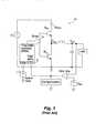
- FIG. 1is a circuit diagram of a conventional switching regulator configured in a buck or step-down topology.
- a high-side switch M HSdrives the switch voltage V SW to the input voltage V IN while a low-side switch M LS drives the switch voltage V SW to the ground potential.
- the high-side switch and the low-side switchare sometimes referred to as power switches or output switching device of the switching regulator.
- the switch voltage V SWis coupled to an output filter circuit including an inductor and a capacitor connected in series between the switch voltage output node and the ground node.
- the output voltage V OUTis generated at a node between the inductor and the capacitor.
- the output voltage V OUTis a voltage stepped down from the input voltage V IN .
- the feedback control circuitincludes an error amplifier for sensing the difference between a reference voltage V Ref and the output voltage V OUT of the switching regulator.
- the detected voltage differenceis coupled to a pulse width modulator (PWM) circuit 12 .
- a system clockprovides the master clock to the PWM circuit.
- PWM circuit 12In response to the error voltage generated by the error amplifier, PWM circuit 12 generates a Gate_Drive control signal to cause either the high-side switch or the low-side switch to turn on, regulating the switch voltage V SW .
- the Gate_Drive control signalcan be a rectangular waveform whose duty cycle is proportional to the error voltage. In the exemplary circuit shown in FIG.
- the Gate_Drive control signalis coupled to a driver circuit 14 for driving the switch transistors M HS and M LS .
- driver circuit 14drives high-side switch M HS with a non-inverted waveform and drives low-side switch M LS with an inverted waveform.
- a PWM switching regulatorprovides regulation by controlling the duty cycle of the rectangular switch voltage V SW that is applied to the inductor and the capacitor of the output filter circuit.
- duty cycleis defined as the percentage of time a switching device is turned on to cause the inductor current to increase.
- the feedback control systemincreases the duty cycle so as to increase the amount of energy provided to the inductor. If the load voltage is too high, the feedback control system decreases the duty cycle so as to decrease the amount of energy provided to the inductor.
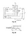
- FIG. 2Ais a circuit diagram illustrating a conventional current mode switching regulator and FIG. 2B illustrates an exemplary inductor current waveform illustrating the operation of the current mode control in the switching regulator of FIG. 2 A.
- FIG. 3Ais a circuit diagram illustrating a conventional voltage mode switching regulator and FIG. 3B illustrates an exemplary inductor voltage waveform illustrating the operation of the voltage mode control in the switching regulator of FIG. 3 A.
- the duty cycleis set by comparing the current in the power stage of the switching regulator to a level set by a voltage control loop. Specifically, the output voltage V OUT is fed back through a voltage divider to one input of a difference amplifier or an error amplifier). The other input is connected to a voltage reference V Ref .
- the difference amplifierprovides an error voltage for driving a PWM comparator, establishing the voltage control loop.
- the output current of the switching regulatoris sensed and the sensed current signal is compared against the error voltage at the PWM comparator, establishing the current control loop.
- the current flowing through the high-side switch M HSis sensed by means of a resistance, depicted as R sense .
- the voltage across the resistanceis compared by PWM comparator to the error voltage generated by the difference amplifier.
- the PWM comparatorgenerates the Gate_Drive control signal to control the power switches.
- the upper switchis turned on long enough so that the current in the inductor ramps up to the threshold set by the error voltage (see FIG. 2 B).
- the duty cycleis set by comparing an error voltage to a ramp signal at a PWM comparator.
- the output voltage V OUTis fed back through a voltage divider to one input of a comparator.
- the comparatorreceives a voltage reference V Ref as the other input and generates an error voltage indicative of the difference between the output voltage V OUT and the reference voltage V Ref .
- the error voltageis coupled to a PWM comparator.
- the PWM comparatorreceives the error voltage and a ramp signal as input where the error voltage sets the threshold of the PWM comparator.
- the output of the PWM comparatoris the Gate_Drive control signal for driving the power switches.
- the error voltagesets the duty cycle of the voltage V SW driving the inductor L of the filter circuit.
- the inductor and the capacitorfunction as a two-pole filter establishing output voltage V out at the average value of the voltage presented to the inductor.
- current mode controlis the higher performance control choice for switching mode power supplies.
- the current mode control methodhas the advantages of simplifying the stabilization of the system and enabling better dynamic performance.
- the superiority of the current mode control methodresults from the fact that current mode control eliminates the complex conjugate pole that the inductor and capacitor naturally create which plagues voltage mode control systems.
- duty cycle controlis provided by sensing the current through the energy storage element (such as the inductor) or through one of the output power switches (that is, current sensing is performed either at the high side switch or the low side switch). In essence, current sensing is performed to control either the peak or the valley of the duty cycle.
- Current sensingcan be carried out by placing a resistor in series with the switches or by using the inherent resistance of the switching device, that is, measuring the voltage across the device. Current sensing can also use a ratioed switching device placed in parallel to the power switch to be sensed to draw a fraction of the current away for measurement.
- the conventional current sensing methodologywill be referred to as a single-sensing scheme.
- a difficulty in the use of the conventional single-sensing schemearises when the operating point of the switching regulator causes the current-sensing window to be very brief.
- the current being sensedmay flow for only a very short time per cycle, leaving a very short time interval for sensing.
- the short sensing intervalcan occur when the system clock frequency is high and/or the duty cycle is at a value close to the extreme (i.e., either 0 or 100 percent) such that the sense current only flows for a small percentage of the cycle time.
- the PWM comparatormust operate at an extremely fast rate. Not only is providing a fast PWM comparator a difficult objective, but such a comparator is typically noise sensitive and therefore not desirable.
- the duty cycle of a switching regulatorwill go to the extreme is when the output voltage to input voltage ratio is steep.
- the PWM comparatorwill have a very short sensing window when the V OUT voltage is a lot smaller than V IN and the duty cycle is accordingly very low.
- This operation regimeis an increasingly commonly-occurring case as technology trends are causing system supply voltages (corresponding to V OUT ) to decrease relative to the input voltage V IN . Consequently, there are increasing numbers of situations in which the duty cycle of a step down switching power supplies will approach zero, making high-side current sensing difficult.
- the high-side sensing problemis solved by sensing current at the low-side switch M LS . Then, when the duty cycle is low, the PWM comparator actually has more time to sense as the sensing is done at the low-side switch which is turned on longer when the duty cycle is low.
- using low-side sensingresults in the same sort of problem at the opposite extreme in duty cycle where the duty cycle is very high.
- the duty cycleis very high, the low-side switch is on for only a very short portion of the cycle.
- a high duty cycle situationtypically occurs in battery-powered applications where, as the battery voltage (corresponding to V IN ) declines due to usage over time, the duty cycle of the switching regulator will go to nearly 100 percent in order to generate the desired V OUT . In the high duty cycle condition, sensing at the low-side switch becomes difficult.
- the initial portion of the sensed signaltypically must be masked off to avoid sensing distortion caused by spurious transient currents.
- the window of time in which the sensing and comparison must occuris in fact even narrower than the theoretical value.
- the inductor currentis always present for sensing, the phase of interest may still be of short duration. For example, if the control architecture senses at the rising phase of the current and the duty cycle is close to zero for this phase, sensing is still difficult because of a narrow sense window. Furthermore, current sensing at the inductor typically involves higher power dissipation due to the use of a resistor in series with the inductor.
- a current mode switching regulatorincludes a first switch and a second switch coupled to drive a switch output node for generating a switch output voltage which switch output voltage is used to generate a regulated output voltage having a substantially constant magnitude.
- the switching regulatorfurther includes a first current sensing circuit for sensing a current through the first switch and providing a first current sense signal, and a second current sensing circuit for sensing a current through the second switch and providing a second current sense signal.
- the switching regulatoralso includes a control circuit for generating a first switch control signal and a second switch control signal for driving the first switch and the second switch respectively for generating the switch output voltage so as to maintain the regulated output voltage at a substantially constant magnitude.
- the control circuitgenerates the switch control signals in response to a selected one of the first and second current sense signals.
- the switching regulatorincludes a duty cycle detection circuit coupled to determine a duty cycle of the switching regulator.
- the duty cycle detection circuitasserts a first select signal when the duty cycle exceeds a first threshold level and asserts a second select signal when the duty cycle is less than a second threshold level, the first threshold level being greater than the second threshold level.
- the control circuitselects the first current sense signal when the first select signal is asserted and the control circuit selects the second current sense signal when the second select signal is asserted.
- the switching regulatorfurther includes an output filter circuit coupled to the switch output node for receiving the switch output voltage and generating the regulated output voltage.
- the first switchis turned on to cause a current into the output filter circuit to increase while the second switch is turned on to cause the current into the output filter circuit to decrease.
- the duty cycleis indicative of the amount of time within a clock period the first switch is turned on.
- the duty cycle detection circuitdetermines the duty cycle of the switching regulator by monitoring the first switch control signal.
- FIG. 1is a circuit diagram of a conventional switching regulator configured in a buck or step-down topology.
- FIG. 2Ais a circuit diagram illustrating a conventional current mode switching regulator.
- FIG. 2Billustrates an exemplary inductor current waveform illustrating the operation of the current mode control in the switching regulator of FIG. 2 A.
- FIG. 3Ais a circuit diagram illustrating a conventional voltage mode switching regulator.
- FIG. 3Billustrates an exemplary inductor voltage waveform illustrating the operation of the voltage mode control in the switching regulator of FIG. 3 A.
- FIG. 4is a diagram illustrating the current sensing scheme according to one embodiment of the present invention.
- FIG. 5is a circuit diagram of a current mode switching regulator in a buck topology implementing the current sensing scheme according to one embodiment of the present invention.
- FIG. 6Aillustrates the regulator operation of the switching regulator of FIG. 5 when high-side sensing is selected.
- FIG. 6Billustrates the regulator operation of the switching regulator of FIG. 5 when low-side sensing is selected.
- FIG. 7is a circuit diagram of a current mode switching regulator in a boost topology implementing the current sensing scheme according to one embodiment of the present invention.
- FIG. 8is a circuit diagram of a current mode switching regulator in a buck topology implementing the current sensing scheme according to another embodiment of the present invention.
- a current mode switching regulatoremploys selective current sensing whereby high-side current sensing and low-side current sensing are both provided and depending on the prevailing duty cycle, the current sense signal with the longer sense window is selected. The selection of the current sense signal in turn enables the switching regulator to assert peak or valley control of the duty cycle. In this manner, effective current mode control is realized as an adequate sensing window is always ensured despite changing operation conditions.
- a switching regulatorperforms current sensing at the energy storage element (such as an inductor) and the current sense signal for the increasing or the decreasing current phase is selected based on the duty cycle to assert peak or valley control of the duty cycle.
- duty cycleis defined as the percentage of time within a system clock period a switching device is turned on to cause the inductor current to increase.
- the duty cycle of the switching regulatoris the percentage of time “D” that the inductor current is increasing within the system clock period “T”.
- the duty cyclerefers to the amount of time the high-side switch is turned on. When the low-side switch is turned on, the inductor current is caused to decrease.
- peak controland “valley control” have their well-known meaning in the art for controlling the duty cycle of a current mode control switching regulator.
- the switching regulatorcontrols when the high-side switch should be turned off to stop the increase of inductor current. Hence, the control is applied to the “peak” of the inductor current waveform.
- valley controlthe switching regulator controls when the low-side switch should be turned off to stop the decrease of inductor current. Hence, the control is applied to the “valley” of the inductor current waveform.
- FIG. 4is a diagram illustrating the current sensing scheme according to one embodiment of the present invention.
- sensing of the current associated with the high-side switch (the high-side current) and the current associated with the low-side switch (the low-side current)is provided.
- the duty cycleis high, high-side sensing mode is selected where the high-side current is sensed (see curve portion A in FIG. 4 ).
- the low-side sensing modeis selected where the low-side current is sensed (see curve portion B in FIG. 4 ).
- the selection of low-side sensing mode and high-side sensing modeis governed by a hysteresis control to avoid “chattering” of or rapid switching back and forth between the two sensing modes.
- the switching regulatorwhen the high-side sensing mode is selected, the switching regulator does not switch to the low-side sensing mode until the duty cycle falls below a low threshold level D L .
- the switching regulatorwhen the low-side sensing mode is selected, the switching regulator will remain at low-side sensing until the duty cycle increases above an upper threshold level D H , where D H is larger than D L and the difference between levels D L and D H includes sufficient margin to avoid chattering of the sensing modes. In this manner, stable transition between the sensing modes is ensured and the switching regulator does not response to transient changes in the duty cycle in operation.
- the transition between high-side sensing and low-side sensingis synchronized to the system clock.
- the lower thresholdis set at 1 ⁇ 3 (or 33.3%) while the upper threshold is set at 2 ⁇ 3 (or 66.7%).
- current sensingis provided at the high-side switch and the low-side switch of a current mode switching regulator.
- current sensingis provided at the energy storage element, such as the inductor.
- current sensingis providing for measuring an increasing inductor current or a decreasing inductor current. It is well understood that an increasing inductor current is associated with the high-side switch being turned on while a decreasing inductor current is associated with the low-side switch being turned on.
- the current sensing scheme of the present inventionis also referred to as a dual-sensing scheme because sensing of both the high-side current and the low-side current is provided. This is in contrast to the single-sensing scheme used in conventional switching regulators where current sensing is only performed at one of the switches.
- FIG. 5is a circuit diagram of a current mode switching regulator in a buck topology implementing the current sensing scheme according to one embodiment of the present invention.
- current mode switching regulator 100includes a duty cycle detection circuit 110 and a control circuit 104 for implementing the dual-sensing scheme of the present invention.
- Switching regulator 100also includes other conventional circuit components, such as output switching devices, a driver circuit and control circuitry.
- FIG. 5also illustrates how the current sensing scheme can be incorporated in any switching regulator topology.
- switching regulator 100includes a high-side switch M HS and a low-side switch M LS , both formed as NMOS transistors.
- the high-side switch and the low-side switchare turned-on alternately to drive switch output node 101 and generate a switch output voltage V SW .
- the switch output voltage V SWdrives an output filter circuit including an inductor L and a capacitor C.
- the switching of voltage V SWcauses the current at the inductor L to increase and decrease.
- an output voltage V OUThaving substantially constant magnitude is created.
- Current mode control in switching regulator 100is provided by coupling output voltage V OUT to a voltage divider including resistors R 1 and R 2 .
- the divided down voltage V FBis fed back to the switching regulator to establish the voltage control loop.
- voltage V FBis coupled to an error amplifier 102 which compares the voltage V FB and a reference voltage V Ref .
- Error amplifier 102generates an error voltage being the difference between the feedback voltage and the reference voltage.
- the error voltageis coupled to control circuit 104 for establishing a voltage level for the PWM comparator which in turn generates a Gate_Drive control signal for controlling the high-side and low-side switches to achieve the desired regulation.
- switching regulator 100the current control loop is established by sensing both the high-side current and the low-side current.
- switching regulator 100includes a first current sensing circuit 120 coupled to the source terminal of high-side switch M HS and a second current sensing circuit 122 coupled to the source terminal of low-side switch M LS .
- Current sensing circuit 120generates a high-side current sense signal CSH and current sensing circuit 122 generates a low-side current sense signal CSL both signals being coupled to control circuit 104 .
- control circuit 104selects which current sense signal to use in the control operation based on the duty cycle of the switch output voltage V SW .
- control circuit 104Besides receiving the error voltage and the current sense signals as input, control circuit 104 also receives a clock signal from a clock generator 106 for establishing the system clock for the switching regulator. Furthermore, control circuit 104 receives a high-side select signal and a low-side select signal from duty cycle detection circuit 110 . Based on the values of the high-side and low-side select signals, control circuit 104 selects one of the two current sense signals for use in the current loop control operation of the switching regulator. In one embodiment, control circuit 104 includes a multiplexer for selecting one of the two current sense signals CSH and CSL based on the high-side and low-side select signals.
- Control circuit 104further includes a PWM comparator and generates a Gate_Drive control signal on output terminal 107 .
- the Gate_Drive signalis coupled to a driver circuit 108 for buffering and signal inversion.
- driver circuit 108provides an inverted Gate_Drive signal to high-side switch M HS as the high-side switch control signal and provides a non-inverted Gate_Drive signal to low-side switch M LS as the low-side switch control signal.
- the switch control signalscan have the same polarities.
- driver circuit 108is powered by a Vdrive voltage from a voltage source 112 .
- the switch control signals generated by the driver circuithave a maximum voltage magnitude of the Vdrive voltage and a minimum voltage magnitude of zero voltage.
- control circuit 104In operation, control circuit 104 generate the Gate_Drive signal based on the error voltage from error amplifier 102 and based on one of the current sense signals from the current sensing circuits 120 and 122 . Control circuit 104 sets the duty cycle of the Gate_Drive signal and thereby sets the duty cycle of the switching devices. When the duty cycle is high, high-side switch M HS is turned on longer to increase the current in inductor L. When the duty cycle is low, high-side switch M HS is turned on for only a short time and low-side switch M LS is turned on longer to decrease the inductor current.
- Duty cycle detection circuit 110receives the Gate_Drive signal as input and operates to generate the high-side and low-side select signals. Specifically, the high-side select signal is asserted when circuit 110 detects a high duty cycle while the low-side select signal is asserted when circuit 100 detects a low duty cycle. In the present embodiment, the high-side select signal is asserted when the duty cycle is greater than 2 ⁇ 3 and the low-side select signal is asserted when the duty cycle is less than 1 ⁇ 3. In the present embodiment, duty cycle detection circuit 110 receives the high side switch control signal as input.
- a logical “hi” value of the high side switch control signalturns on the high-side switch and can therefore be used as an indication of the duty cycle of the switch output voltage V SW .
- the high side switch control signalis coupled to a low pass filter to remove high frequency transients and to average out the voltage levels of the switch control signal waveform.
- the filtered duty cycle signal on terminal 115is indicative of the average voltage magnitude of the high side switch control signal.
- the filtered signalwill have a voltage magnitude greater than 2 ⁇ 3 of the maximum voltage (the Vdrive voltage). If the duty cycle is less than 1 ⁇ 3, then the filtered signal will have a voltage magnitude less than 1 ⁇ 3 of the maximum voltage (the Vdrive voltage).
- the filtered duty cycle signalis coupled to a first comparator 116 and a second comparator 118 .
- Comparator 116compares the filtered duty cycle signal with a high duty cycle threshold level D H .
- the filtered duty cycle signalis coupled to the positive input terminal while the high duty cycle threshold level D H is coupled to the negative input terminal.
- comparator 116asserts its output signal—the high-side select signal.
- comparator 118compares the filtered duty cycle signal with a low duty cycle threshold level D L .
- the filtered duty cycle signalis coupled to the negative input terminal while the low duty cycle threshold level D L is coupled to the positive input terminal.
- comparator 118asserts its output signal—the low-side select signal.
- the high duty cycle threshold level D H and the low duty cycle threshold level D Lare established using a resistor divider including resistors R 3 , R 4 and R 5 , all of equal resistance.
- the resistor divideris connected between voltage Vdrive and the ground potential.
- the divided down voltages generated by the resistor divideris proportional to the magnitude of the switch control signals generated by driver circuit 108 .
- the divided down voltagescan thus be effectively used to determine the duty cycle of the switch control signals.
- the high duty cycle threshold level D His generated at a node 117 between resistors R 3 and R 4 .
- the high duty cycle threshold level D Hrepresents 2 ⁇ 3 of the Vdrive voltage.
- the low duty cycle threshold level D Lis generated at a node 119 between resistors R 4 and R 5 .
- the low duty cycle threshold level D Lrepresents 1 ⁇ 3 of the Vdrive voltage.
- different duty cycle threshold levelscan be established by using different resistance values for resistors R 3 , R 4 and R 5 .
- the duty level threshold levelsshould be spaced apart sufficient to implement an effective hysteresis operation.
- the high-side switch control signalis low-pass filtered to generate a filtered duty cycle signal being the average voltage value of the high-side switch control signal.
- the filtered duty cycle signalis coupled to first comparator 116 and second comparator 118 for determining the state of the duty cycle.
- the filtered duty cycle signalhas a voltage value greater than 2 ⁇ 3 of the Vdrive voltage
- the high-side select signalwill be asserted.
- the filtered duty cycle signalhas a voltage value less than 1 ⁇ 3 of the Vdrive voltage
- the low-side select signalwill be asserted.
- FIG. 6Aillustrates the regulator operation when high-side sensing is selected while FIG. 6B illustrates the regulator operation when low-side sensing is selected.
- switching regulator 100The operation of switching regulator 100 is triggered by the system clock.
- control circuit 104examines the status of the high-side select signal and the low-side select signal to determine whether high-side sensing or low-side sensing has been selected.
- the high-side switch control signalis asserted on the rising edge of the system clock.
- high-side switch M HSis turned on and switch output voltage V SW is forced to the V IN voltage, thereby causing the inductor current to increase.
- the output voltage V OUTis fed back to error amplifier 102 for generating the error voltage for control circuit 104 .
- control circuit 104Based on the error voltage and the current sense signal CSH, control circuit 104 provides current mode control for the switching regulator. Specifically, when the inductor rises to the level set by the error voltage, the PWM comparator in control circuit 104 triggers its output signal (as indicated in FIG. 6A at time t 1 ). The PWM comparator trigger causes the high-side switch control signal to be deasserted and the low-side switch control signal to be asserted. As a result, the inductor current decreases. The switching regulator remains in this state until the next system clock system.
- the duty cycleis high and therefore a sufficiently large sensing window is provided at the high-side switch for current sensing.
- the duty cycleis continuously being monitored by duty cycle detection circuit 110 .
- Duty cycle detector circuit 110continues to assert the high-side select signal until the duty cycle has fallen below the preselected threshold which is 1 ⁇ 3 in the present embodiment.
- switching regulatorhas a duty cycle of greater than 2 ⁇ 3 and is therefore in high-side sensing mode during the first and second clock periods (P 1 and P 2 ).
- P 3 and P 4the third and fourth clock periods
- duty cycle detector circuit 110when duty cycle detector circuit 110 detects that the duty cycle of the switching regulator has dropped to below 1 ⁇ 3, such as by monitoring the high-side switch control signal, the duty cycle detection circuit asserts the low-side select signal and deassert the high-side select signal. In this manner, switching regulator 100 switches to low-side current sensing at low duty cycle. When the duty cycle is low, the sensing window for the low-side switch current is longer, allowing effective current measurements to be made.
- the transition between high-side and low-side sensingoccurs at the start of the system clock.
- the low-side switch control signalis asserted and low-side switch M LS is turned on and switch output voltage V SW is forced to the V SS or ground voltage, thereby causing the inductor current to decrease.
- the output voltage V OUTis fed back to error amplifier 102 for generating the error voltage for control circuit 104 .
- the low-side currentis being sensed by sensing circuit 122 and the low-side current sense signal CSL is also provided to control circuit 104 . Based on the error voltage and the current sense signal CSL, control circuit 104 provides current mode control for the switching regulator.
- the PWM comparator in control circuit 104triggers its output signal (as indicated in FIG. 6B at time t 2 ).
- the PWM comparator triggercauses the low-side switch control signal to be deasserted and the high-side switch control signal to be asserted.
- the inductor currentincreases.
- the switching regulatorremains in this state until the next system clock system.
- switching regulator 100transitions between high-side sensing to low-side sensing when the duty cycle drops to the preselected level.
- a large sensing window for the low-side switch currentis provided for effective current measurement.
- the operation of switching regulator 100remains in the low-side sensing mode (system clock periods P 5 and P 6 ) until the duty cycle increases above the preselected level which is 2 ⁇ 3 in the present embodiment.
- the duty cyclehas increased so that the on-time for low-side switch M LS becomes very small, reducing the sensing window for the low-side switch current.
- Duty cycle detection circuit 110will accordingly assert the high-side select signal and deassert the low-side select signal so that switching regulator transitions to high-side sensing at the next system clock.
- the switching regulator of the present inventionBy selectively engaging either high-side sensing or low-side sensing based on the duty cycle, the switching regulator of the present invention is ensured to have a long sensing window for current sensing no matter what the duty cycle is.
- the switching regulator of the present inventioncan provide effective current mode control over a wide range of duty cycle variations, including duty cycle variations between 0 to 100 percent. Furthermore, based on the selected current sensing mode, the switching regulator practices peak or valley control thereby providing improved current mode control performance.
- FIG. 5illustrates the incorporation of the current sensing scheme of the present invention in a current mode switching regulator in a buck topology.
- the current sensing scheme of the present inventionis applicable to other switching regulator topologies as well, such as the boost topology or the buck-boost topology.
- FIG. 7is a circuit diagram of a current mode switching regulator in a boost topology implementing the current sensing scheme according to one embodiment of the present invention.
- switching regulator 200includes an NMOS transistor as the high-side switch and a PMOS transistor as the low-side switch.
- the inductoris coupled between the input voltage V IN and the switch output node 201 .
- the NMOS transitoryis coupled between the switch output node 201 and the ground node.
- the PMOS transistoris coupled between the switch output node 201 and the capacitor C for generating the output voltage V OUT .
- duty cycleis defined as the percentage of each system clock cycle that the NMOS transistor (the high-side switch) is on.
- a first current sensing circuit 220is provided to sense the current at the NMOS transistor and a second current sensing circuit 222 is provided to sense the current at the PMOS transistor.
- a duty cycle detection circuit 210is coupled to monitor the NMOS switch control signal as the NMOS switch control signal determines the duty cycle. Duty cycle detection circuit 210 generates a NMOS select signal and a PMOS select signal whereby depending on the duty cycle, only one of the select signals will be asserted.
- a control circuit 204is coupled to receive the error voltage from the feedback voltage, the current sense signal and the select signals. The control circuit 204 operates to select high-side sensing at the NMOS transistor when the duty cycle is high and to select low-side sensing at the PMOS transistor when the duty cycle is low.
- FIG. 8is a circuit diagram of a current mode switching regulator in a buck topology implementing the current sensing scheme according to another embodiment of the present invention. In the configuration shown in FIG. 8 , the current sensing scheme of the present invention is applied to provide peak and valley control.
- switching regulator 300 of FIG. 8includes a current sensing circuit 320 at the output terminal (voltage V OUT ) of the inductor L.
- a duty cycle detection circuit 310is incorporated in switching regulator 300 to monitor the high-side switch control signal which is indicative of the duty cycle.
- duty cycle detection circuitasserts the high-side select signal to cause control circuit 304 to apply valley control to regulate the output voltage V OUT .
- duty cycle detection circuit 310asserts the low-side select signal which causes control circuit 304 to apply peak control to regulate the output voltage V OUT . In this manner, current sensing is always performed at the phase of the inductor current with the longer sensing window.
- the duty cycle detection circuit of the present inventionis illustrated as including a low pass filter and a pair of comparators for generating the select signals. Furthermore, a resistor divider is used to establish the comparator threshold levels for implementing hysteresis control.
- the circuit configuration of the duty cycle detection circuit in the above descriptionsis illustrative only and is not intended to be limiting.
- the duty cycle detection circuitcan assume other circuit configuration for monitoring the duty cycle and generating select signals for the control circuit.
- the exact configuration of the duty cycle detection circuitis not critical to the implementation of the current sensing scheme of the present invention. For example, the duty cycle could be computed by comparing the on-times of the gate drive signals of high-side switch M HS and low-side switch M LS .
- the threshold levels for the hysteresis controlcan be implemented by other means.
- the dual-sensing scheme of the present inventionprovides many advantages.
- First, the dual-sensing schemeenables effective current sensing for duty cycle that varies between 0 to 100 percent. Therefore, a switching regulator implementing the dual-sensing scheme can have improved current mode control regardless of the duty cycle variations.
- the switching regulator implementing the dual-sensing scheme of the present inventioncan have wide application and its performance is not degraded due to large variations in duty cycle such as that caused by changing load conditions or changing input voltage values.
- the current sensing scheme of the present inventionis described as being applied to inductor-based switching regulators.
- the dual current sensing scheme of the present inventioncan also be applied to a transformer-based switching regulator, also known as isolated switching regulators.
- Transformer-based switching regulatorssuffer the same constraints as inductor-based systems in that at extremes of duty cycle, the current sensing window can be very short. Therefore, the dual sensing scheme of the present invention can be advantageously applied to improve the current sensing capability and the current mode control performance of transformer-based switching regulators.
Landscapes
- Engineering & Computer Science (AREA)
- Power Engineering (AREA)
- Dc-Dc Converters (AREA)
Abstract
Description
D=VOUT/VIN.
Claims (36)
Priority Applications (1)
| Application Number | Priority Date | Filing Date | Title |
|---|---|---|---|
| US10/639,066US6853174B1 (en) | 2003-08-11 | 2003-08-11 | Selective high-side and low-side current sensing in switching power supplies |
Applications Claiming Priority (1)
| Application Number | Priority Date | Filing Date | Title |
|---|---|---|---|
| US10/639,066US6853174B1 (en) | 2003-08-11 | 2003-08-11 | Selective high-side and low-side current sensing in switching power supplies |
Publications (2)
| Publication Number | Publication Date |
|---|---|
| US6853174B1true US6853174B1 (en) | 2005-02-08 |
| US20050035748A1 US20050035748A1 (en) | 2005-02-17 |
Family
ID=34104633
Family Applications (1)
| Application Number | Title | Priority Date | Filing Date |
|---|---|---|---|
| US10/639,066Expired - LifetimeUS6853174B1 (en) | 2003-08-11 | 2003-08-11 | Selective high-side and low-side current sensing in switching power supplies |
Country Status (1)
| Country | Link |
|---|---|
| US (1) | US6853174B1 (en) |
Cited By (50)
| Publication number | Priority date | Publication date | Assignee | Title |
|---|---|---|---|---|
| US20040123167A1 (en)* | 2002-12-23 | 2004-06-24 | Power -One Limited | System and method for interleaving point-of-load regulators |
| US20040232970A1 (en)* | 2003-05-20 | 2004-11-25 | Matsushita Electric Industrial Co. Ltd. | Level shift circuit |
| US20050105311A1 (en)* | 2003-10-01 | 2005-05-19 | International Rectifier Corporation | Bridge-less boost (BLB) power factor correction topology controlled with one cycle control |
| US20050180065A1 (en)* | 2004-02-12 | 2005-08-18 | Alain Chapuis | System and method for managing fault in a power system |
| US20050194839A1 (en)* | 2004-02-17 | 2005-09-08 | Agere Systems Inc. | Versatile and intelligent power controller |
| US20050200344A1 (en)* | 2002-11-12 | 2005-09-15 | Alain Chapuis | System and method for controlling a point-of-load regulator |
| US20060015616A1 (en)* | 2002-11-12 | 2006-01-19 | Power-One Limited | Digital power manager for controlling and monitoring an array of point-of-load regulators |
| US20060043942A1 (en)* | 2004-05-13 | 2006-03-02 | Isaac Cohen | Power converter apparatus and methods using output current feedforward control |
| US20060069935A1 (en)* | 2003-03-14 | 2006-03-30 | Thaker Mahesh N | Voltage set point control scheme |
| US20060066379A1 (en)* | 2004-09-30 | 2006-03-30 | Hopsecger Edward C | Current loop drive module with dynamic compliance voltage |
| US20060171175A1 (en)* | 2005-02-03 | 2006-08-03 | On-Bright Electronics (Shanghai) Co., Ltd. | Adaptive multi-level threshold system and method for power converter protection |
| US20060198172A1 (en)* | 2003-10-01 | 2006-09-07 | International Rectifier Corporation | Bridgeless boost converter with PFC circuit |
| US20060255783A1 (en)* | 2005-05-10 | 2006-11-16 | Power-One Limited | Bi-directional MOS current sense circuit |
| US20070124612A1 (en)* | 2002-12-21 | 2007-05-31 | Power-One, Inc. | Method and system for controlling a mixed array of point-of-load regulators through a bus translator |
| US20070182391A1 (en)* | 2005-03-18 | 2007-08-09 | Power-One, Inc. | Digital double-loop output voltage regulation |
| US20070226526A1 (en)* | 2002-12-21 | 2007-09-27 | Alain Chapuis | Method and system for controlling and monitoring an array of point-of-load regulators |
| US20070240000A1 (en)* | 2002-12-21 | 2007-10-11 | Alain Chapuis | Method and system for controlling and monitoring an array of point-of-load regulators |
| US7298124B2 (en)* | 2004-12-01 | 2007-11-20 | Semiconductor Components Industries, L.L.C. | PWM regulator with discontinuous mode and method therefor |
| US20080010474A1 (en)* | 2002-12-21 | 2008-01-10 | Power-One, Inc. | Method And System For Optimizing Filter Compensation Coefficients For A Digital Power Control System |
| US20080018364A1 (en)* | 2006-07-21 | 2008-01-24 | Clarkin John P | Capacitively coupled floating gate driver |
| US7327130B1 (en)* | 2006-06-21 | 2008-02-05 | Zilker Labs, Inc. | Current sense method |
| US20080042632A1 (en)* | 2003-02-10 | 2008-02-21 | Alain Chapuis | Self tracking adc for digital power supply control systems |
| US20080052551A1 (en)* | 2002-12-21 | 2008-02-28 | Alain Chapuis | System For Controlling An Array Of Point-Of-Load Regulators And Auxiliary Devices |
| US20080072080A1 (en)* | 2002-11-13 | 2008-03-20 | Alain Chapuis | Method And System For Controlling And Monitoring An Array Of Point-Of-Load Regulators |
| US20080088283A1 (en)* | 2006-10-10 | 2008-04-17 | Kabushiki Kaisha Toshiba | Dc-dc converter |
| US20080186006A1 (en)* | 2002-12-21 | 2008-08-07 | Alain Chapuis | Method and system for communicating filter compensation coefficients for a digital power control system |
| US20080204084A1 (en)* | 2007-02-28 | 2008-08-28 | Terdan Dale R | Low heat dissipation i/o module using direct drive buck converter |
| WO2008106049A1 (en)* | 2007-02-28 | 2008-09-04 | Hewlett-Packard Development Company, L.P. | Gate drive voltage selection for a voltage regulator |
| US20080252274A1 (en)* | 2007-04-13 | 2008-10-16 | Advanced Analogic Technologies, Inc. | Pseudo Fixed Frequency Switch-Mode DC/DC Voltage Regulator Control Method |
| US20080316775A1 (en)* | 2007-06-22 | 2008-12-25 | Lead Year Enterprise Co., Ltd. | Soft-switching circuit for power supply |
| US20090108833A1 (en)* | 2007-10-30 | 2009-04-30 | Silvio Ziegler | Isolated current to voltage, voltage to voltage converter |
| US20100320975A1 (en)* | 2009-06-22 | 2010-12-23 | Seagate Technology Llc | Quasi-continuous voltage regulator with dual polarity outputs |
| US20110234255A1 (en)* | 2010-03-25 | 2011-09-29 | Cree Led Lighting Solutions, Inc. | Fault detection circuits for switched mode power supplies and related methods of operation |
| US8086874B2 (en) | 2002-12-21 | 2011-12-27 | Power-One, Inc. | Method and system for controlling an array of point-of-load regulators and auxiliary devices |
| US20120126769A1 (en)* | 2010-11-18 | 2012-05-24 | Renesas Electronics Corporation | Voltage boosting/lowering circuit and voltage boosting/lowering circuit control method |
| US20120139507A1 (en)* | 2010-12-05 | 2012-06-07 | Microsemi Corporation | Hysteretic voltage converter with offset voltage correction |
| US20130162230A1 (en)* | 2011-12-22 | 2013-06-27 | Fujitsu Semiconductor Limited | Dc-dc converter and method of controlling dc-dc converter |
| US20130293211A1 (en)* | 2012-05-07 | 2013-11-07 | Anpec Electronics Corporation | Method and Apparatus for All Duty Current Sensing in Current Mode Converter |
| US20160043628A1 (en)* | 2014-08-05 | 2016-02-11 | Power Forest Technology Corporation | Power conversion apparatus and protection method thereof while feedback current signal being abnormal |
| US20170085168A1 (en)* | 2015-09-22 | 2017-03-23 | Intersil Americas LLC | Method and System for Reducing Transients in DC-DC Converters |
| US20180212508A1 (en)* | 2017-01-20 | 2018-07-26 | Canon Kabushiki Kaisha | Power supply apparatus and image forming apparatus |
| US10056833B2 (en)* | 2015-05-12 | 2018-08-21 | Hamilton Sundstrand Corporation | Voltage regulator for inductive loads |
| TWI657653B (en)* | 2018-06-12 | 2019-04-21 | 大陸商昂寶電子(上海)有限公司 | Power conversion system |
| US10840797B2 (en)* | 2018-11-26 | 2020-11-17 | Texas Instruments Incorporated | Load release detection circuit |
| US11018584B2 (en)* | 2019-06-04 | 2021-05-25 | Texas Instruments Incorporated | Adaptive minimum on time control for a switching regulator |
| US11038421B2 (en) | 2016-04-14 | 2021-06-15 | Texas Instruments Incorporated | Methods and apparatus for adaptive timing for zero voltage transition power converters |
| CN114660352A (en)* | 2020-12-23 | 2022-06-24 | 意法半导体股份有限公司 | Current monitoring circuit, corresponding system and method |
| US11594967B2 (en) | 2021-04-27 | 2023-02-28 | Apple Inc. | Hysteretic current control switching power converter with clock-controlled switching frequency |
| US20240030799A1 (en)* | 2022-07-25 | 2024-01-25 | Elite Semiconductor Microelectronics Technology Inc. | Control circuit with automatic frequency modulation for dc-dc converter |
| US12055568B2 (en) | 2022-07-26 | 2024-08-06 | Nxp Usa, Inc. | Dual current sensing |
Families Citing this family (22)
| Publication number | Priority date | Publication date | Assignee | Title |
|---|---|---|---|---|
| CN1856929A (en)* | 2003-09-25 | 2006-11-01 | 皇家飞利浦电子股份有限公司 | A switch mode power converter |
| US7301288B2 (en)* | 2004-04-08 | 2007-11-27 | International Rectifier Corporation | LED buck regulator control IC |
| US7919952B1 (en)* | 2005-03-21 | 2011-04-05 | Microsemi Corporation | Automatic gain control technique for current monitoring in current-mode switching regulators |
| EP2039004A2 (en)* | 2006-06-30 | 2009-03-25 | Nxp B.V. | Circuit for detecting the duty cycle of clock signals |
| US7812585B2 (en)* | 2007-05-29 | 2010-10-12 | Linear Technology Corporation | Advanced current-mode control for switched regulators |
| US8305059B2 (en)* | 2008-12-30 | 2012-11-06 | Texas Instruments Incorporated | Voltage regulator circuit |
| US8310793B2 (en)* | 2009-07-21 | 2012-11-13 | Infineon Technologies Ag | Over-current protection for DC-to-DC converters |
| GB0912745D0 (en)* | 2009-07-22 | 2009-08-26 | Wolfson Microelectronics Plc | Improvements relating to DC-DC converters |
| US8278895B2 (en)* | 2009-12-24 | 2012-10-02 | Linear Technology Corporation | Efficiency measuring circuit for DC-DC converter which calculates internal resistance of switching inductor based on duty cycle |
| JP5667761B2 (en)* | 2009-12-28 | 2015-02-12 | 株式会社東芝 | Switching power supply |
| KR101133497B1 (en)* | 2010-04-30 | 2012-04-05 | 매그나칩 반도체 유한회사 | LED driving circuit for back light and driving method thereof and back light driving apparatus |
| US8629669B2 (en) | 2010-07-27 | 2014-01-14 | Volterra Semiconductor Corporation | Sensing and feedback in a current mode control voltage regulator |
| DE102011101916B4 (en)* | 2011-05-18 | 2019-05-02 | Austriamicrosystems Ag | DC / DC converter and method for controlling the current of a DC / DC converter |
| US9156364B2 (en)* | 2012-02-14 | 2015-10-13 | Ut-Battelle, Llc | Wireless power charging using point of load controlled high frequency power converters |
| US20140084884A1 (en)* | 2012-07-06 | 2014-03-27 | Jong J. Lee | Lc switching regulators |
| EP2728725B1 (en)* | 2012-10-30 | 2017-08-02 | Dialog Semiconductor GmbH | Hysteretic power converter with current shaping |
| US9504103B2 (en)* | 2013-10-21 | 2016-11-22 | Osram Sylvania Inc. | Driving a multi-color luminaire |
| US9712054B2 (en)* | 2014-06-13 | 2017-07-18 | Nxp Usa, Inc. | Voltage and current limits for electronic device based on temperature range |
| WO2016061816A1 (en)* | 2014-10-24 | 2016-04-28 | Texas Instruments Incorporated | Soft start controller of a converter |
| US10205448B2 (en)* | 2016-05-19 | 2019-02-12 | Joulwatt Technology (Hangzhou) Co., Ltd. | Switch control circuit and switch circuit |
| US10680522B2 (en)* | 2017-02-09 | 2020-06-09 | Rohm Co., Ltd. | Switching regulator and control device therefor |
| US12191769B2 (en)* | 2022-10-07 | 2025-01-07 | Infineon Technologies Austria Ag | Current mode controller and corresponding method of operation |
Citations (1)
| Publication number | Priority date | Publication date | Assignee | Title |
|---|---|---|---|---|
| US6166528A (en)* | 1999-11-02 | 2000-12-26 | Fairchild Semiconductor Corporation | Lossless current sensing in buck converters working with low duty cycles and high clock frequencies |
- 2003
- 2003-08-11USUS10/639,066patent/US6853174B1/ennot_activeExpired - Lifetime
Patent Citations (1)
| Publication number | Priority date | Publication date | Assignee | Title |
|---|---|---|---|---|
| US6166528A (en)* | 1999-11-02 | 2000-12-26 | Fairchild Semiconductor Corporation | Lossless current sensing in buck converters working with low duty cycles and high clock frequencies |
Cited By (106)
| Publication number | Priority date | Publication date | Assignee | Title |
|---|---|---|---|---|
| US7394445B2 (en) | 2002-11-12 | 2008-07-01 | Power-One, Inc. | Digital power manager for controlling and monitoring an array of point-of-load regulators |
| US7459892B2 (en) | 2002-11-12 | 2008-12-02 | Power-One, Inc. | System and method for controlling a point-of-load regulator |
| US20060015616A1 (en)* | 2002-11-12 | 2006-01-19 | Power-One Limited | Digital power manager for controlling and monitoring an array of point-of-load regulators |
| US20050200344A1 (en)* | 2002-11-12 | 2005-09-15 | Alain Chapuis | System and method for controlling a point-of-load regulator |
| US7782029B2 (en) | 2002-11-13 | 2010-08-24 | Power-One, Inc. | Method and system for controlling and monitoring an array of point-of-load regulators |
| US20080072080A1 (en)* | 2002-11-13 | 2008-03-20 | Alain Chapuis | Method And System For Controlling And Monitoring An Array Of Point-Of-Load Regulators |
| US20080186006A1 (en)* | 2002-12-21 | 2008-08-07 | Alain Chapuis | Method and system for communicating filter compensation coefficients for a digital power control system |
| US20070124612A1 (en)* | 2002-12-21 | 2007-05-31 | Power-One, Inc. | Method and system for controlling a mixed array of point-of-load regulators through a bus translator |
| US7737961B2 (en) | 2002-12-21 | 2010-06-15 | Power-One, Inc. | Method and system for controlling and monitoring an array of point-of-load regulators |
| US7743266B2 (en) | 2002-12-21 | 2010-06-22 | Power-One, Inc. | Method and system for optimizing filter compensation coefficients for a digital power control system |
| US7673157B2 (en) | 2002-12-21 | 2010-03-02 | Power-One, Inc. | Method and system for controlling a mixed array of point-of-load regulators through a bus translator |
| US20080052551A1 (en)* | 2002-12-21 | 2008-02-28 | Alain Chapuis | System For Controlling An Array Of Point-Of-Load Regulators And Auxiliary Devices |
| US7565559B2 (en) | 2002-12-21 | 2009-07-21 | Power-One, Inc. | Method and system for communicating filter compensation coefficients for a digital power control system |
| US7836322B2 (en) | 2002-12-21 | 2010-11-16 | Power-One, Inc. | System for controlling an array of point-of-load regulators and auxiliary devices |
| US7882372B2 (en) | 2002-12-21 | 2011-02-01 | Power-One, Inc. | Method and system for controlling and monitoring an array of point-of-load regulators |
| US20080010474A1 (en)* | 2002-12-21 | 2008-01-10 | Power-One, Inc. | Method And System For Optimizing Filter Compensation Coefficients For A Digital Power Control System |
| US8086874B2 (en) | 2002-12-21 | 2011-12-27 | Power-One, Inc. | Method and system for controlling an array of point-of-load regulators and auxiliary devices |
| US20070240000A1 (en)* | 2002-12-21 | 2007-10-11 | Alain Chapuis | Method and system for controlling and monitoring an array of point-of-load regulators |
| US20070226526A1 (en)* | 2002-12-21 | 2007-09-27 | Alain Chapuis | Method and system for controlling and monitoring an array of point-of-load regulators |
| US7373527B2 (en) | 2002-12-23 | 2008-05-13 | Power-One, Inc. | System and method for interleaving point-of-load regulators |
| US20040123167A1 (en)* | 2002-12-23 | 2004-06-24 | Power -One Limited | System and method for interleaving point-of-load regulators |
| US7493504B2 (en) | 2002-12-23 | 2009-02-17 | Power-One, Inc. | System and method for interleaving point-of-load regulators |
| US20080048625A1 (en)* | 2002-12-23 | 2008-02-28 | Alain Chapuis | System and method for interleaving point-of-load regulators |
| US7710092B2 (en) | 2003-02-10 | 2010-05-04 | Power-One, Inc. | Self tracking ADC for digital power supply control systems |
| US20080042632A1 (en)* | 2003-02-10 | 2008-02-21 | Alain Chapuis | Self tracking adc for digital power supply control systems |
| US7526660B2 (en) | 2003-03-14 | 2009-04-28 | Power-One, Inc. | Voltage set point control scheme |
| US20060069935A1 (en)* | 2003-03-14 | 2006-03-30 | Thaker Mahesh N | Voltage set point control scheme |
| US20040232970A1 (en)* | 2003-05-20 | 2004-11-25 | Matsushita Electric Industrial Co. Ltd. | Level shift circuit |
| US6963238B2 (en)* | 2003-05-20 | 2005-11-08 | Matsushita Electric Industrial Co., Ltd. | Level shift circuit |
| US20050105311A1 (en)* | 2003-10-01 | 2005-05-19 | International Rectifier Corporation | Bridge-less boost (BLB) power factor correction topology controlled with one cycle control |
| US7164591B2 (en)* | 2003-10-01 | 2007-01-16 | International Rectifier Corporation | Bridge-less boost (BLB) power factor correction topology controlled with one cycle control |
| US20060198172A1 (en)* | 2003-10-01 | 2006-09-07 | International Rectifier Corporation | Bridgeless boost converter with PFC circuit |
| US7554778B2 (en) | 2004-02-12 | 2009-06-30 | Power-One, Inc. | System and method for managing fault in a power system |
| US20080049363A1 (en)* | 2004-02-12 | 2008-02-28 | Alain Chapuis | System And Method For Managing Fault In A Power System |
| US7372682B2 (en) | 2004-02-12 | 2008-05-13 | Power-One, Inc. | System and method for managing fault in a power system |
| US20080052016A1 (en)* | 2004-02-12 | 2008-02-28 | Alain Chapuis | System And Method For Managing Fault In A Power System |
| US7583487B2 (en) | 2004-02-12 | 2009-09-01 | Power-One, Inc. | System and method for managing fault in a power system |
| US20050180065A1 (en)* | 2004-02-12 | 2005-08-18 | Alain Chapuis | System and method for managing fault in a power system |
| GB2426131A (en)* | 2004-02-17 | 2006-11-15 | Agere Systems Inc | Versatile and intelligent power controller |
| US20070120423A1 (en)* | 2004-02-17 | 2007-05-31 | Agere Systems Inc. | Switching Power Supply Controller With Built-In Supply Switching |
| WO2005079430A3 (en)* | 2004-02-17 | 2006-08-03 | Agere Systems Inc | Versatile and intelligent power controller |
| US7595569B2 (en)* | 2004-02-17 | 2009-09-29 | Agere Systems Inc. | Versatile and intelligent power controller |
| GB2426131B (en)* | 2004-02-17 | 2008-01-23 | Agere Systems Inc | Versatile and intelligent power controller |
| US20050194839A1 (en)* | 2004-02-17 | 2005-09-08 | Agere Systems Inc. | Versatile and intelligent power controller |
| US20100019579A1 (en)* | 2004-02-17 | 2010-01-28 | Agere Systems Inc. | Versatile and intelligent power controller |
| US7956494B2 (en) | 2004-02-17 | 2011-06-07 | Agere Systems Inc. | Versatile and intelligent power controller |
| US20060043942A1 (en)* | 2004-05-13 | 2006-03-02 | Isaac Cohen | Power converter apparatus and methods using output current feedforward control |
| US20080074373A1 (en)* | 2004-07-16 | 2008-03-27 | Alain Chapuis | Digital Power Manager For Controlling And Monitoring An Array Of Point-Of-Load Regulators |
| US7646382B2 (en) | 2004-07-16 | 2010-01-12 | Power-One, Inc. | Digital power manager for controlling and monitoring an array of point-of-load regulators |
| US20060066379A1 (en)* | 2004-09-30 | 2006-03-30 | Hopsecger Edward C | Current loop drive module with dynamic compliance voltage |
| US7205818B2 (en)* | 2004-09-30 | 2007-04-17 | Rockwell Automation Technologies, Inc. | Current loop drive module with dynamic compliance voltage |
| US7298124B2 (en)* | 2004-12-01 | 2007-11-20 | Semiconductor Components Industries, L.L.C. | PWM regulator with discontinuous mode and method therefor |
| US7345895B2 (en)* | 2005-02-03 | 2008-03-18 | On-Bright Electronics (Shanghai) Co., Ltd. | Adaptive multi-level threshold system and method for power converter protection |
| US20060171175A1 (en)* | 2005-02-03 | 2006-08-03 | On-Bright Electronics (Shanghai) Co., Ltd. | Adaptive multi-level threshold system and method for power converter protection |
| US7099164B2 (en)* | 2005-02-03 | 2006-08-29 | On-Bright Electronics (Shanghai) Co., Ltd. | Adaptive multi-level threshold system and method for power converter protection |
| US20060291258A1 (en)* | 2005-02-03 | 2006-12-28 | On-Bright Electronics (Shanghai) Co., Ltd. | Adaptive multi-level threshold system and method for power converter protection |
| US7554310B2 (en) | 2005-03-18 | 2009-06-30 | Power-One, Inc. | Digital double-loop output voltage regulation |
| US20070182391A1 (en)* | 2005-03-18 | 2007-08-09 | Power-One, Inc. | Digital double-loop output voltage regulation |
| US20060255783A1 (en)* | 2005-05-10 | 2006-11-16 | Power-One Limited | Bi-directional MOS current sense circuit |
| US7327149B2 (en)* | 2005-05-10 | 2008-02-05 | Power-One, Inc. | Bi-directional MOS current sense circuit |
| US7327130B1 (en)* | 2006-06-21 | 2008-02-05 | Zilker Labs, Inc. | Current sense method |
| US7368957B2 (en)* | 2006-07-21 | 2008-05-06 | Picor Corporation | Capacitively coupled floating gate driver |
| US20080018364A1 (en)* | 2006-07-21 | 2008-01-24 | Clarkin John P | Capacitively coupled floating gate driver |
| US20080088283A1 (en)* | 2006-10-10 | 2008-04-17 | Kabushiki Kaisha Toshiba | Dc-dc converter |
| US7675275B2 (en) | 2006-10-10 | 2010-03-09 | Kabushiki Kaisha Toshiba | DC-DC converter |
| US20080204084A1 (en)* | 2007-02-28 | 2008-08-28 | Terdan Dale R | Low heat dissipation i/o module using direct drive buck converter |
| US7804287B2 (en) | 2007-02-28 | 2010-09-28 | Rockwell Automation Technologies, Inc. | Low heat dissipation I/O module using direct drive buck converter |
| US7814345B2 (en) | 2007-02-28 | 2010-10-12 | Hewlett-Packard Development Company, L.P. | Gate drive voltage selection for a voltage regulator |
| CN101622775B (en)* | 2007-02-28 | 2014-06-11 | 惠普开发有限公司 | Gate Drive Voltage Selection for Voltage Regulators |
| WO2008106049A1 (en)* | 2007-02-28 | 2008-09-04 | Hewlett-Packard Development Company, L.P. | Gate drive voltage selection for a voltage regulator |
| US20080252274A1 (en)* | 2007-04-13 | 2008-10-16 | Advanced Analogic Technologies, Inc. | Pseudo Fixed Frequency Switch-Mode DC/DC Voltage Regulator Control Method |
| US8446136B2 (en)* | 2007-04-13 | 2013-05-21 | Advanced Analogic Technologies, Inc. | Pseudo fixed frequency switch-mode DC/DC voltage regulator control method |
| US20080316775A1 (en)* | 2007-06-22 | 2008-12-25 | Lead Year Enterprise Co., Ltd. | Soft-switching circuit for power supply |
| US7834613B2 (en) | 2007-10-30 | 2010-11-16 | Power-One, Inc. | Isolated current to voltage, voltage to voltage converter |
| US20090108833A1 (en)* | 2007-10-30 | 2009-04-30 | Silvio Ziegler | Isolated current to voltage, voltage to voltage converter |
| US20100320975A1 (en)* | 2009-06-22 | 2010-12-23 | Seagate Technology Llc | Quasi-continuous voltage regulator with dual polarity outputs |
| US8159202B2 (en)* | 2009-06-22 | 2012-04-17 | Seagate Technology Llc | Quasi-continuous voltage regulator with dual polarity outputs |
| US8680884B2 (en)* | 2010-03-25 | 2014-03-25 | Cree, Inc. | Fault detection circuits for switched mode power supplies and related methods of operation |
| US20110234255A1 (en)* | 2010-03-25 | 2011-09-29 | Cree Led Lighting Solutions, Inc. | Fault detection circuits for switched mode power supplies and related methods of operation |
| US20120126769A1 (en)* | 2010-11-18 | 2012-05-24 | Renesas Electronics Corporation | Voltage boosting/lowering circuit and voltage boosting/lowering circuit control method |
| US9106135B2 (en) | 2010-11-18 | 2015-08-11 | Renesas Electronics Corporation | Voltage boosting/lowering circuit and voltage boosting/lowering circuit control method |
| US8823347B2 (en)* | 2010-11-18 | 2014-09-02 | Renesas Electronics Corporation | Voltage boosting/lowering circuit and voltage boosting/lowering circuit control method |
| US8441245B2 (en)* | 2010-12-05 | 2013-05-14 | Microsemi Corporation | Hysteretic voltage converter with offset voltage correction |
| US20120139507A1 (en)* | 2010-12-05 | 2012-06-07 | Microsemi Corporation | Hysteretic voltage converter with offset voltage correction |
| US20130162230A1 (en)* | 2011-12-22 | 2013-06-27 | Fujitsu Semiconductor Limited | Dc-dc converter and method of controlling dc-dc converter |
| US8872496B2 (en)* | 2011-12-22 | 2014-10-28 | Fujitsu Semiconductor Limited | DC-DC converter and method of controlling DC-DC converter |
| US20130293211A1 (en)* | 2012-05-07 | 2013-11-07 | Anpec Electronics Corporation | Method and Apparatus for All Duty Current Sensing in Current Mode Converter |
| US8922186B2 (en)* | 2012-05-07 | 2014-12-30 | Anpec Electronics Corporation | Method and apparatus for all duty current sensing in current mode converter |
| US20160043628A1 (en)* | 2014-08-05 | 2016-02-11 | Power Forest Technology Corporation | Power conversion apparatus and protection method thereof while feedback current signal being abnormal |
| US9729043B2 (en)* | 2014-08-05 | 2017-08-08 | Power Forest Technology Corporation | Power conversion apparatus and protection method thereof while feedback current signal being abnormal |
| US10056833B2 (en)* | 2015-05-12 | 2018-08-21 | Hamilton Sundstrand Corporation | Voltage regulator for inductive loads |
| US10768678B2 (en) | 2015-09-22 | 2020-09-08 | Intersil Americas LLC | Method and system for reducing transients in DC-DC converters |
| US20170085168A1 (en)* | 2015-09-22 | 2017-03-23 | Intersil Americas LLC | Method and System for Reducing Transients in DC-DC Converters |
| US10073507B2 (en)* | 2015-09-22 | 2018-09-11 | Intersil Americas LLC | Method and system for reducing transients in DC-DC converters |
| US11038421B2 (en) | 2016-04-14 | 2021-06-15 | Texas Instruments Incorporated | Methods and apparatus for adaptive timing for zero voltage transition power converters |
| US20180212508A1 (en)* | 2017-01-20 | 2018-07-26 | Canon Kabushiki Kaisha | Power supply apparatus and image forming apparatus |
| US10536084B2 (en)* | 2017-01-20 | 2020-01-14 | Canon Kabushiki Kaisha | Power supply apparatus and image forming apparatus |
| TWI657653B (en)* | 2018-06-12 | 2019-04-21 | 大陸商昂寶電子(上海)有限公司 | Power conversion system |
| US10840797B2 (en)* | 2018-11-26 | 2020-11-17 | Texas Instruments Incorporated | Load release detection circuit |
| US11018584B2 (en)* | 2019-06-04 | 2021-05-25 | Texas Instruments Incorporated | Adaptive minimum on time control for a switching regulator |
| US11671012B2 (en) | 2019-06-04 | 2023-06-06 | Texas Instruments Incorporated | Adaptive minimum on time control for a switching regulator |
| CN114660352A (en)* | 2020-12-23 | 2022-06-24 | 意法半导体股份有限公司 | Current monitoring circuit, corresponding system and method |
| US11594967B2 (en) | 2021-04-27 | 2023-02-28 | Apple Inc. | Hysteretic current control switching power converter with clock-controlled switching frequency |
| US20240030799A1 (en)* | 2022-07-25 | 2024-01-25 | Elite Semiconductor Microelectronics Technology Inc. | Control circuit with automatic frequency modulation for dc-dc converter |
| US12040693B2 (en)* | 2022-07-25 | 2024-07-16 | Elite Semiconductor Microelectronics Technology Inc. | Control circuit with automatic frequency modulation for DC-DC converter |
| US12055568B2 (en) | 2022-07-26 | 2024-08-06 | Nxp Usa, Inc. | Dual current sensing |
Also Published As
| Publication number | Publication date |
|---|---|
| US20050035748A1 (en) | 2005-02-17 |
Similar Documents
| Publication | Publication Date | Title |
|---|---|---|
| US6853174B1 (en) | Selective high-side and low-side current sensing in switching power supplies | |
| US11303212B2 (en) | Peak-buck peak-boost current-mode control for switched step-up step-down regulators | |
| US9837899B2 (en) | Power converter with improved load transient response and associated control method | |
| US7064531B1 (en) | PWM buck regulator with LDO standby mode | |
| US9231574B2 (en) | Power converter, clock module and associated control method | |
| JP3647811B2 (en) | DC-DC converter circuit | |
| TWI594558B (en) | Switching converter and its controller and mode control circuit | |
| US6671143B2 (en) | Technique for limiting current through a reactive element in a voltage converter | |
| JP6001570B2 (en) | Switching control of PWM operation and PFM operation in step-down converter | |
| US7394231B2 (en) | Current-mode control for switched step up-step down regulators | |
| USRE46333E1 (en) | High-side sensing of zero inductor current for step-down DC-DC converter | |
| USRE46045E1 (en) | Hysteretic controlled buck-boost converter | |
| JPH10225105A (en) | Dc-dc converter | |
| US20060176036A1 (en) | Variable frequency current-mode control for switched step up-step down regulators | |
| US7256570B2 (en) | Light load current-mode control for switched step up-step down regulators | |
| TW201509100A (en) | Duty-cycle dependent slope compensation for a current mode switching regulator | |
| US20090267573A1 (en) | Power Supplies, Power Supply Controllers, And Power Supply Controlling Methods | |
| KR20080009083A (en) | Adaptive Power Control for Hysteresis Regulators | |
| US6809560B1 (en) | Load sensing circuit for a power MOSFET switch | |
| US20220052597A1 (en) | Driving circuit and driving method | |
| EP3002860A1 (en) | Peak-buck peak-boost current-mode control for switched step-up step-down regulators | |
| US12401276B2 (en) | Control circuit for regulating output voltage of a buck converter during negative load transients | |
| US10720839B1 (en) | System and method for operating a switching converter in light load | |
| US12374983B2 (en) | Control device for a switching voltage regulator having improved control performance and control method | |
| CN119310352A (en) | Current sensing circuit and current sensing method |
Legal Events
| Date | Code | Title | Description |
|---|---|---|---|
| AS | Assignment | Owner name:MICREL INC, CALIFORNIA Free format text:ASSIGNMENT OF ASSIGNORS INTEREST;ASSIGNOR:INN, BRUCE L.;REEL/FRAME:014392/0022 Effective date:20030808 | |
| AS | Assignment | Owner name:MICREL, INC., CALIFORNIA Free format text:CORRECTIVE ASSIGNMENT TO CORRECT THE ASSIGNMENT DOCUMENTS STATE OF INCORPORATION. DOCUMENT PREVIOUSLY RECORDED AT REEL 014392 FRAME 0022;ASSIGNOR:INN, BRUCE L.;REEL/FRAME:015075/0779 Effective date:20030808 | |
| STCF | Information on status: patent grant | Free format text:PATENTED CASE | |
| FPAY | Fee payment | Year of fee payment:4 | |
| FPAY | Fee payment | Year of fee payment:8 | |
| FPAY | Fee payment | Year of fee payment:12 | |
| AS | Assignment | Owner name:JPMORGAN CHASE BANK, N.A., AS ADMINISTRATIVE AGENT, DELAWARE Free format text:SECURITY INTEREST;ASSIGNORS:MICROCHIP TECHNOLOGY INC.;SILICON STORAGE TECHNOLOGY, INC.;ATMEL CORPORATION;AND OTHERS;REEL/FRAME:053311/0305 Effective date:20200327 | |
| AS | Assignment | Owner name:MICROSEMI STORAGE SOLUTIONS, INC., ARIZONA Free format text:RELEASE BY SECURED PARTY;ASSIGNOR:JPMORGAN CHASE BANK, N.A, AS ADMINISTRATIVE AGENT;REEL/FRAME:053466/0011 Effective date:20200529 Owner name:MICROCHIP TECHNOLOGY INC., ARIZONA Free format text:RELEASE BY SECURED PARTY;ASSIGNOR:JPMORGAN CHASE BANK, N.A, AS ADMINISTRATIVE AGENT;REEL/FRAME:053466/0011 Effective date:20200529 Owner name:ATMEL CORPORATION, ARIZONA Free format text:RELEASE BY SECURED PARTY;ASSIGNOR:JPMORGAN CHASE BANK, N.A, AS ADMINISTRATIVE AGENT;REEL/FRAME:053466/0011 Effective date:20200529 Owner name:SILICON STORAGE TECHNOLOGY, INC., ARIZONA Free format text:RELEASE BY SECURED PARTY;ASSIGNOR:JPMORGAN CHASE BANK, N.A, AS ADMINISTRATIVE AGENT;REEL/FRAME:053466/0011 Effective date:20200529 Owner name:MICROSEMI CORPORATION, CALIFORNIA Free format text:RELEASE BY SECURED PARTY;ASSIGNOR:JPMORGAN CHASE BANK, N.A, AS ADMINISTRATIVE AGENT;REEL/FRAME:053466/0011 Effective date:20200529 | |
| AS | Assignment | Owner name:WELLS FARGO BANK, NATIONAL ASSOCIATION, MINNESOTA Free format text:SECURITY INTEREST;ASSIGNORS:MICROCHIP TECHNOLOGY INC.;SILICON STORAGE TECHNOLOGY, INC.;ATMEL CORPORATION;AND OTHERS;REEL/FRAME:053468/0705 Effective date:20200529 | |
| AS | Assignment | Owner name:WELLS FARGO BANK, NATIONAL ASSOCIATION, AS COLLATERAL AGENT, MINNESOTA Free format text:SECURITY INTEREST;ASSIGNORS:MICROCHIP TECHNOLOGY INCORPORATED;SILICON STORAGE TECHNOLOGY, INC.;ATMEL CORPORATION;AND OTHERS;REEL/FRAME:055671/0612 Effective date:20201217 | |
| AS | Assignment | Owner name:WELLS FARGO BANK, NATIONAL ASSOCIATION, AS NOTES COLLATERAL AGENT, MINNESOTA Free format text:SECURITY INTEREST;ASSIGNORS:MICROCHIP TECHNOLOGY INCORPORATED;SILICON STORAGE TECHNOLOGY, INC.;ATMEL CORPORATION;AND OTHERS;REEL/FRAME:057935/0474 Effective date:20210528 | |
| AS | Assignment | Owner name:MICROSEMI STORAGE SOLUTIONS, INC., ARIZONA Free format text:RELEASE BY SECURED PARTY;ASSIGNOR:WELLS FARGO BANK, NATIONAL ASSOCIATION, AS NOTES COLLATERAL AGENT;REEL/FRAME:059863/0400 Effective date:20220228 Owner name:MICROSEMI CORPORATION, ARIZONA Free format text:RELEASE BY SECURED PARTY;ASSIGNOR:WELLS FARGO BANK, NATIONAL ASSOCIATION, AS NOTES COLLATERAL AGENT;REEL/FRAME:059863/0400 Effective date:20220228 Owner name:ATMEL CORPORATION, ARIZONA Free format text:RELEASE BY SECURED PARTY;ASSIGNOR:WELLS FARGO BANK, NATIONAL ASSOCIATION, AS NOTES COLLATERAL AGENT;REEL/FRAME:059863/0400 Effective date:20220228 Owner name:SILICON STORAGE TECHNOLOGY, INC., ARIZONA Free format text:RELEASE BY SECURED PARTY;ASSIGNOR:WELLS FARGO BANK, NATIONAL ASSOCIATION, AS NOTES COLLATERAL AGENT;REEL/FRAME:059863/0400 Effective date:20220228 Owner name:MICROCHIP TECHNOLOGY INCORPORATED, ARIZONA Free format text:RELEASE BY SECURED PARTY;ASSIGNOR:WELLS FARGO BANK, NATIONAL ASSOCIATION, AS NOTES COLLATERAL AGENT;REEL/FRAME:059863/0400 Effective date:20220228 | |
| AS | Assignment | Owner name:MICROSEMI STORAGE SOLUTIONS, INC., ARIZONA Free format text:RELEASE BY SECURED PARTY;ASSIGNOR:WELLS FARGO BANK, NATIONAL ASSOCIATION, AS NOTES COLLATERAL AGENT;REEL/FRAME:059363/0001 Effective date:20220228 Owner name:MICROSEMI CORPORATION, ARIZONA Free format text:RELEASE BY SECURED PARTY;ASSIGNOR:WELLS FARGO BANK, NATIONAL ASSOCIATION, AS NOTES COLLATERAL AGENT;REEL/FRAME:059363/0001 Effective date:20220228 Owner name:ATMEL CORPORATION, ARIZONA Free format text:RELEASE BY SECURED PARTY;ASSIGNOR:WELLS FARGO BANK, NATIONAL ASSOCIATION, AS NOTES COLLATERAL AGENT;REEL/FRAME:059363/0001 Effective date:20220228 Owner name:SILICON STORAGE TECHNOLOGY, INC., ARIZONA Free format text:RELEASE BY SECURED PARTY;ASSIGNOR:WELLS FARGO BANK, NATIONAL ASSOCIATION, AS NOTES COLLATERAL AGENT;REEL/FRAME:059363/0001 Effective date:20220228 Owner name:MICROCHIP TECHNOLOGY INCORPORATED, ARIZONA Free format text:RELEASE BY SECURED PARTY;ASSIGNOR:WELLS FARGO BANK, NATIONAL ASSOCIATION, AS NOTES COLLATERAL AGENT;REEL/FRAME:059363/0001 Effective date:20220228 | |
| AS | Assignment | Owner name:MICROSEMI STORAGE SOLUTIONS, INC., ARIZONA Free format text:RELEASE BY SECURED PARTY;ASSIGNOR:WELLS FARGO BANK, NATIONAL ASSOCIATION, AS NOTES COLLATERAL AGENT;REEL/FRAME:060894/0437 Effective date:20220228 Owner name:MICROSEMI CORPORATION, ARIZONA Free format text:RELEASE BY SECURED PARTY;ASSIGNOR:WELLS FARGO BANK, NATIONAL ASSOCIATION, AS NOTES COLLATERAL AGENT;REEL/FRAME:060894/0437 Effective date:20220228 Owner name:ATMEL CORPORATION, ARIZONA Free format text:RELEASE BY SECURED PARTY;ASSIGNOR:WELLS FARGO BANK, NATIONAL ASSOCIATION, AS NOTES COLLATERAL AGENT;REEL/FRAME:060894/0437 Effective date:20220228 Owner name:SILICON STORAGE TECHNOLOGY, INC., ARIZONA Free format text:RELEASE BY SECURED PARTY;ASSIGNOR:WELLS FARGO BANK, NATIONAL ASSOCIATION, AS NOTES COLLATERAL AGENT;REEL/FRAME:060894/0437 Effective date:20220228 Owner name:MICROCHIP TECHNOLOGY INCORPORATED, ARIZONA Free format text:RELEASE BY SECURED PARTY;ASSIGNOR:WELLS FARGO BANK, NATIONAL ASSOCIATION, AS NOTES COLLATERAL AGENT;REEL/FRAME:060894/0437 Effective date:20220228 | |
| AS | Assignment | Owner name:MICROCHIP TECHNOLOGY INCORPORATED, ARIZONA Free format text:INTELLECTUAL PROPERTY BUY-IN AGREEMENT/ASSIGNMENT;ASSIGNOR:MICREL LLC;REEL/FRAME:063241/0771 Effective date:20151101 |