US6852291B1 - Hybrid valve apparatus and method for fluid handling - Google Patents
Hybrid valve apparatus and method for fluid handlingDownload PDFInfo
- Publication number
- US6852291B1 US6852291B1US09/689,548US68954800AUS6852291B1US 6852291 B1US6852291 B1US 6852291B1US 68954800 AUS68954800 AUS 68954800AUS 6852291 B1US6852291 B1US 6852291B1
- Authority
- US
- United States
- Prior art keywords
- dispensing
- aspiration
- condition
- port
- actuator
- Prior art date
- Legal status (The legal status is an assumption and is not a legal conclusion. Google has not performed a legal analysis and makes no representation as to the accuracy of the status listed.)
- Expired - Lifetime, expires
Links
Images


Classifications
- G—PHYSICS
- G01—MEASURING; TESTING
- G01N—INVESTIGATING OR ANALYSING MATERIALS BY DETERMINING THEIR CHEMICAL OR PHYSICAL PROPERTIES
- G01N35/00—Automatic analysis not limited to methods or materials provided for in any single one of groups G01N1/00 - G01N33/00; Handling materials therefor
- G01N35/10—Devices for transferring samples or any liquids to, in, or from, the analysis apparatus, e.g. suction devices, injection devices
- G01N35/1095—Devices for transferring samples or any liquids to, in, or from, the analysis apparatus, e.g. suction devices, injection devices for supplying the samples to flow-through analysers
- G01N35/1097—Devices for transferring samples or any liquids to, in, or from, the analysis apparatus, e.g. suction devices, injection devices for supplying the samples to flow-through analysers characterised by the valves
- B—PERFORMING OPERATIONS; TRANSPORTING
- B01—PHYSICAL OR CHEMICAL PROCESSES OR APPARATUS IN GENERAL
- B01J—CHEMICAL OR PHYSICAL PROCESSES, e.g. CATALYSIS OR COLLOID CHEMISTRY; THEIR RELEVANT APPARATUS
- B01J19/00—Chemical, physical or physico-chemical processes in general; Their relevant apparatus
- B01J19/0046—Sequential or parallel reactions, e.g. for the synthesis of polypeptides or polynucleotides; Apparatus and devices for combinatorial chemistry or for making molecular arrays
- F—MECHANICAL ENGINEERING; LIGHTING; HEATING; WEAPONS; BLASTING
- F16—ENGINEERING ELEMENTS AND UNITS; GENERAL MEASURES FOR PRODUCING AND MAINTAINING EFFECTIVE FUNCTIONING OF MACHINES OR INSTALLATIONS; THERMAL INSULATION IN GENERAL
- F16K—VALVES; TAPS; COCKS; ACTUATING-FLOATS; DEVICES FOR VENTING OR AERATING
- F16K11/00—Multiple-way valves, e.g. mixing valves; Pipe fittings incorporating such valves
- F16K11/02—Multiple-way valves, e.g. mixing valves; Pipe fittings incorporating such valves with all movable sealing faces moving as one unit
- F16K11/06—Multiple-way valves, e.g. mixing valves; Pipe fittings incorporating such valves with all movable sealing faces moving as one unit comprising only sliding valves, i.e. sliding closure elements
- F16K11/072—Multiple-way valves, e.g. mixing valves; Pipe fittings incorporating such valves with all movable sealing faces moving as one unit comprising only sliding valves, i.e. sliding closure elements with pivoted closure members
- F16K11/074—Multiple-way valves, e.g. mixing valves; Pipe fittings incorporating such valves with all movable sealing faces moving as one unit comprising only sliding valves, i.e. sliding closure elements with pivoted closure members with flat sealing faces
- F16K11/0743—Multiple-way valves, e.g. mixing valves; Pipe fittings incorporating such valves with all movable sealing faces moving as one unit comprising only sliding valves, i.e. sliding closure elements with pivoted closure members with flat sealing faces with both the supply and the discharge passages being on one side of the closure plates
- F—MECHANICAL ENGINEERING; LIGHTING; HEATING; WEAPONS; BLASTING
- F16—ENGINEERING ELEMENTS AND UNITS; GENERAL MEASURES FOR PRODUCING AND MAINTAINING EFFECTIVE FUNCTIONING OF MACHINES OR INSTALLATIONS; THERMAL INSULATION IN GENERAL
- F16K—VALVES; TAPS; COCKS; ACTUATING-FLOATS; DEVICES FOR VENTING OR AERATING
- F16K99/00—Subject matter not provided for in other groups of this subclass
- F16K99/0001—Microvalves
- F16K99/0003—Constructional types of microvalves; Details of the cutting-off member
- F16K99/0013—Rotary valves
- F—MECHANICAL ENGINEERING; LIGHTING; HEATING; WEAPONS; BLASTING
- F16—ENGINEERING ELEMENTS AND UNITS; GENERAL MEASURES FOR PRODUCING AND MAINTAINING EFFECTIVE FUNCTIONING OF MACHINES OR INSTALLATIONS; THERMAL INSULATION IN GENERAL
- F16K—VALVES; TAPS; COCKS; ACTUATING-FLOATS; DEVICES FOR VENTING OR AERATING
- F16K99/00—Subject matter not provided for in other groups of this subclass
- F16K99/0001—Microvalves
- F16K99/0003—Constructional types of microvalves; Details of the cutting-off member
- F16K99/0028—Valves having multiple inlets or outlets
- G—PHYSICS
- G01—MEASURING; TESTING
- G01N—INVESTIGATING OR ANALYSING MATERIALS BY DETERMINING THEIR CHEMICAL OR PHYSICAL PROPERTIES
- G01N1/00—Sampling; Preparing specimens for investigation
- G01N1/02—Devices for withdrawing samples
- G01N1/10—Devices for withdrawing samples in the liquid or fluent state
- G01N1/14—Suction devices, e.g. pumps; Ejector devices
- B—PERFORMING OPERATIONS; TRANSPORTING
- B01—PHYSICAL OR CHEMICAL PROCESSES OR APPARATUS IN GENERAL
- B01J—CHEMICAL OR PHYSICAL PROCESSES, e.g. CATALYSIS OR COLLOID CHEMISTRY; THEIR RELEVANT APPARATUS
- B01J2219/00—Chemical, physical or physico-chemical processes in general; Their relevant apparatus
- B01J2219/00274—Sequential or parallel reactions; Apparatus and devices for combinatorial chemistry or for making arrays; Chemical library technology
- B01J2219/00277—Apparatus
- B01J2219/00279—Features relating to reactor vessels
- B01J2219/00306—Reactor vessels in a multiple arrangement
- B01J2219/00313—Reactor vessels in a multiple arrangement the reactor vessels being formed by arrays of wells in blocks
- B01J2219/00315—Microtiter plates
- B—PERFORMING OPERATIONS; TRANSPORTING
- B01—PHYSICAL OR CHEMICAL PROCESSES OR APPARATUS IN GENERAL
- B01J—CHEMICAL OR PHYSICAL PROCESSES, e.g. CATALYSIS OR COLLOID CHEMISTRY; THEIR RELEVANT APPARATUS
- B01J2219/00—Chemical, physical or physico-chemical processes in general; Their relevant apparatus
- B01J2219/00274—Sequential or parallel reactions; Apparatus and devices for combinatorial chemistry or for making arrays; Chemical library technology
- B01J2219/00277—Apparatus
- B01J2219/00351—Means for dispensing and evacuation of reagents
- B01J2219/00389—Feeding through valves
- B01J2219/00391—Rotary valves
- B01J2219/00394—Rotary valves in multiple arrangements
- B—PERFORMING OPERATIONS; TRANSPORTING
- B01—PHYSICAL OR CHEMICAL PROCESSES OR APPARATUS IN GENERAL
- B01J—CHEMICAL OR PHYSICAL PROCESSES, e.g. CATALYSIS OR COLLOID CHEMISTRY; THEIR RELEVANT APPARATUS
- B01J2219/00—Chemical, physical or physico-chemical processes in general; Their relevant apparatus
- B01J2219/00274—Sequential or parallel reactions; Apparatus and devices for combinatorial chemistry or for making arrays; Chemical library technology
- B01J2219/00277—Apparatus
- B01J2219/00351—Means for dispensing and evacuation of reagents
- B01J2219/00389—Feeding through valves
- B01J2219/00409—Solenoids in combination with valves
- B01J2219/00412—In multiple arrangements
- B—PERFORMING OPERATIONS; TRANSPORTING
- B01—PHYSICAL OR CHEMICAL PROCESSES OR APPARATUS IN GENERAL
- B01J—CHEMICAL OR PHYSICAL PROCESSES, e.g. CATALYSIS OR COLLOID CHEMISTRY; THEIR RELEVANT APPARATUS
- B01J2219/00—Chemical, physical or physico-chemical processes in general; Their relevant apparatus
- B01J2219/00274—Sequential or parallel reactions; Apparatus and devices for combinatorial chemistry or for making arrays; Chemical library technology
- B01J2219/00583—Features relative to the processes being carried out
- B01J2219/00603—Making arrays on substantially continuous surfaces
- B01J2219/00605—Making arrays on substantially continuous surfaces the compounds being directly bound or immobilised to solid supports
- B—PERFORMING OPERATIONS; TRANSPORTING
- B01—PHYSICAL OR CHEMICAL PROCESSES OR APPARATUS IN GENERAL
- B01J—CHEMICAL OR PHYSICAL PROCESSES, e.g. CATALYSIS OR COLLOID CHEMISTRY; THEIR RELEVANT APPARATUS
- B01J2219/00—Chemical, physical or physico-chemical processes in general; Their relevant apparatus
- B01J2219/00274—Sequential or parallel reactions; Apparatus and devices for combinatorial chemistry or for making arrays; Chemical library technology
- B01J2219/00583—Features relative to the processes being carried out
- B01J2219/00603—Making arrays on substantially continuous surfaces
- B01J2219/00659—Two-dimensional arrays
- C—CHEMISTRY; METALLURGY
- C40—COMBINATORIAL TECHNOLOGY
- C40B—COMBINATORIAL CHEMISTRY; LIBRARIES, e.g. CHEMICAL LIBRARIES
- C40B60/00—Apparatus specially adapted for use in combinatorial chemistry or with libraries
- C40B60/14—Apparatus specially adapted for use in combinatorial chemistry or with libraries for creating libraries
- F—MECHANICAL ENGINEERING; LIGHTING; HEATING; WEAPONS; BLASTING
- F16—ENGINEERING ELEMENTS AND UNITS; GENERAL MEASURES FOR PRODUCING AND MAINTAINING EFFECTIVE FUNCTIONING OF MACHINES OR INSTALLATIONS; THERMAL INSULATION IN GENERAL
- F16K—VALVES; TAPS; COCKS; ACTUATING-FLOATS; DEVICES FOR VENTING OR AERATING
- F16K99/00—Subject matter not provided for in other groups of this subclass
- F16K2099/0082—Microvalves adapted for a particular use
- F16K2099/0084—Chemistry or biology, e.g. "lab-on-a-chip" technology
- G—PHYSICS
- G01—MEASURING; TESTING
- G01N—INVESTIGATING OR ANALYSING MATERIALS BY DETERMINING THEIR CHEMICAL OR PHYSICAL PROPERTIES
- G01N35/00—Automatic analysis not limited to methods or materials provided for in any single one of groups G01N1/00 - G01N33/00; Handling materials therefor
- G01N35/10—Devices for transferring samples or any liquids to, in, or from, the analysis apparatus, e.g. suction devices, injection devices
- G01N2035/1027—General features of the devices
- G01N2035/1034—Transferring microquantities of liquid
- G01N2035/1041—Ink-jet like dispensers
- Y—GENERAL TAGGING OF NEW TECHNOLOGICAL DEVELOPMENTS; GENERAL TAGGING OF CROSS-SECTIONAL TECHNOLOGIES SPANNING OVER SEVERAL SECTIONS OF THE IPC; TECHNICAL SUBJECTS COVERED BY FORMER USPC CROSS-REFERENCE ART COLLECTIONS [XRACs] AND DIGESTS
- Y10—TECHNICAL SUBJECTS COVERED BY FORMER USPC
- Y10T—TECHNICAL SUBJECTS COVERED BY FORMER US CLASSIFICATION
- Y10T137/00—Fluid handling
- Y10T137/8593—Systems
- Y10T137/86493—Multi-way valve unit
- Y10T137/86863—Rotary valve unit
- Y—GENERAL TAGGING OF NEW TECHNOLOGICAL DEVELOPMENTS; GENERAL TAGGING OF CROSS-SECTIONAL TECHNOLOGIES SPANNING OVER SEVERAL SECTIONS OF THE IPC; TECHNICAL SUBJECTS COVERED BY FORMER USPC CROSS-REFERENCE ART COLLECTIONS [XRACs] AND DIGESTS
- Y10—TECHNICAL SUBJECTS COVERED BY FORMER USPC
- Y10T—TECHNICAL SUBJECTS COVERED BY FORMER US CLASSIFICATION
- Y10T137/00—Fluid handling
- Y10T137/8593—Systems
- Y10T137/87249—Multiple inlet with multiple outlet
- Y—GENERAL TAGGING OF NEW TECHNOLOGICAL DEVELOPMENTS; GENERAL TAGGING OF CROSS-SECTIONAL TECHNOLOGIES SPANNING OVER SEVERAL SECTIONS OF THE IPC; TECHNICAL SUBJECTS COVERED BY FORMER USPC CROSS-REFERENCE ART COLLECTIONS [XRACs] AND DIGESTS
- Y10—TECHNICAL SUBJECTS COVERED BY FORMER USPC
- Y10T—TECHNICAL SUBJECTS COVERED BY FORMER US CLASSIFICATION
- Y10T436/00—Chemistry: analytical and immunological testing
- Y10T436/25—Chemistry: analytical and immunological testing including sample preparation
- Y10T436/2575—Volumetric liquid transfer
Definitions
- the present inventionrelates to fabrication, apparatus, system and methods for manipulating arrays of samples, reagents or solvents from a source or reservoir to a destination substrate, and more particularly, relates to a hybrid valve system applied to aspirate, dispense and switch fluids during large-scale chemical or biochemical screening assays, syntheses, arraying and plate spotting.
- drop-on demand ink jet technologyhas been adopted for accurately delivering volumes on the order of picoliters. This technology is not only capable of volumetric precision, by but also positional accuracy as well.
- These ink jet systemstypically employ thermal, piezoelectric, or solenoid actuation to deliver defined volumes of liquid sample to precise locations, increasing test site array density.
- the present inventionprovides a hybrid valve apparatus for use with an aspiration actuator and a dispensing actuator to transfer fluid from a reservoir to a test site on a substrate surface.
- the hybrid valveincludes a valve assembly movable between an aspiration condition and a dispensing condition, and a manifold device coupled to the valve assembly.
- the manifold deviceincludes a fluid aspiration conduit having a first aspiration port in fluid communication with the aspiration actuator.
- On an opposite end of the aspiration conduitis a second aspiration port in selective fluid communication with the valve assembly to selectively aspirate a liquid sample slug from the reservoir into a discrete sample path when the valve assembly is in the aspiration condition.
- the manifold devicefurther includes a fluid dispensing conduit having a first dispensing port in fluid communication with the dispensing actuator, and a second dispensing port in selective fluid communication with the valve assembly.
- a fluid dispensing conduithaving a first dispensing port in fluid communication with the dispensing actuator, and a second dispensing port in selective fluid communication with the valve assembly.
- the hybrid valveincludes a plurality of aspiration actuators and a plurality of dispensing actuators to transfer fluid from a plurality of fluid reservoirs to a plurality of test sites on the substrate surface.
- the manifold devicedefines a plurality of independent fluid aspiration conduits, each of which includes a first aspiration port in fluid communication with a corresponding one of the plurality of aspiration actuators, and a second aspiration port terminating at a stator face of the manifold for selective fluid communication with the valve assembly.
- each aspiration actuatorcan be operated to selectively aspirate a respective liquid sample slug from a corresponding reservoir of sample fluid into discrete sample paths.
- the manifold devicefurther defines a plurality of fluid dispensing conduits, each having a respective first dispensing port in fluid communication with a corresponding one of the plurality of dispensing actuators, and a second dispensing port terminating at the stator face.
- each dispensing actuatorcan be operated to selectively dispense at least one droplet of the corresponding liquid sample slug from the corresponding sample path.
- each fluid pathis operatively switched between the aspiration actuator and the dispensing actuator enabling the use of conventional liquid handling techniques, such as air gaps, to isolate system hydraulic fluid during aspiration, and the subsequent low-volume, non-contact dispensing of the reagents or sample fluid to the test site.
- the manifold deviceincludes a stator face configured for rotational sliding contact with a rotor face of the valve assembly at a rotor-stator interface.
- Each of the second aspiration ports and the second dispensing portsterminate at the stator face for communication with the valve assembly.
- the manifold devicefurther includes a plurality of primary passages each defining at least a portion of their respective sample paths.
- Each primary passagehas a upper communication port which also terminates at the stator face. The upper communication port remains in fluid communication with the respective sample channel when in the aspiration condition and the dispensing condition.
- the primary passageis fluidly coupled to the respective aspiration actuator in the aspiration condition, and fluidly coupled to the respective dispensing actuator in the dispensing condition.
- the hybrid valvemay include a plurality of removable nozzle members mounted to the manifold device to dispense the respective droplet.
- Each nozzleincludes one end fluidly coupled to a corresponding primary passage and an opposite end terminating at a dispensing orifice.
- the manifold devicemay be provided by a plurality of laminated plate members which collectively define the body of the manifold. At least two plate members are fixedly mounted together in a manner cooperatively defining at least one of the aspiration conduits and the dispensing conduits.
- the two plate membersinclude a first plate member having a first interface surface and a second plate member having an opposed second interface surface fixedly joined therebetween at a first interface. This first interface surface defines a plurality of first grooves which cooperate with the second interface surface of the second plate member to define at least the aspiration conduits or the dispensing conduits.
- the dispensing actuatorsmay include drop-on demand ink-jet printing valving in the form of a thermal ink-jet valve, a solenoid ink-jet valve, or a piezoelectric ink-jet valve.
- the aspiration actuatorsmay include a syringe-type metering device.
- a methodfor transferring liquid sample from a fluid reservoir to a test site on a target substrate.
- the methodincludes providing a fluid manifold device defining a fluid aspiration conduit having a first aspiration port in fluid communication with an aspiration actuator and a second aspiration port in fluid communication with the valve assembly.
- the manifold devicefurther defines a fluid dispensing conduit having a first dispensing port in fluid communication with the dispensing actuator and a second dispensing port in fluid communication with the valve assembly.
- the methodincludes positioning the valve assembly in an aspiration condition, fluidly coupling the aspiration actuator to a discrete sample path, and fluidly decoupling the dispensing actuator from the sample path; and actuating the aspiration actuator to aspirate a liquid sample slug from a sample reservoir into the sample path.
- the methodfurther includes positioning the valve assembly in a dispensing condition, fluidly coupling the dispensing actuator to the sample path, and fluidly decoupling the aspiration actuator from the same path.
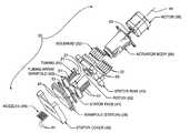
- FIG. 1is a top perspective view of the hybrid valve apparatus constructed in accordance with the present invention.
- FIG. 2is an exploded top perspective view of the hybrid valve apparatus of FIG. 1 .
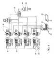
- FIG. 3is a schematic illustration of an assembly incorporating the hybrid valve apparatus of FIG. 1 .
- FIG. 4Ais a top perspective view of a manifold device of the hybrid valve apparatus of FIG. 1 , and illustrating the stator face interface.
- FIG. 4Bis a bottom perspective view illustrating the lower communication ports of the manifold device of FIG. 4 A.
- FIG. 5is an enlarged, exploded bottom perspective view of one fluid path of the hybrid valve apparatus in the aspiration condition.
- FIG. 6is an enlarged, exploded bottom perspective view of one fluid path of the hybrid valve apparatus in the dispensing condition.
- FIG. 7is an enlarged, top plan view of a stator face of a stator element of the manifold device.
- FIG. 8is an enlarged, bottom plan view of a rotor face of a rotor element of the valve assembly.
- FIG. 9is a top plan view of the manifold device with the rotor face superimposed over the stator face at a rotor/stator interface in the aspiration condition.
- FIG. 10is an enlarged top plan view of the rotor/stator interface of FIG. 9 , in the aspiration condition.
- FIG. 11is a top plan view of the manifold device of FIG. 9 in the dispensing condition.
- FIG. 12is an enlarged top plan view of the rotor/stator interface of FIG. 11 , in the dispensing condition.
- FIG. 13is an exploded, enlarged bottom plan view of the manifold device of FIG. 4B , illustrating the channels and grooves of the individual plate members.
- FIG. 14is an enlarged, fragmentary, illustration of the exploded bottom plan view of FIG. 13 .
- FIG. 15is an exploded bottom perspective view of one fluid path of an alternative embodiment hybrid valve apparatus in the aspiration condition.
- FIG. 16is an exploded bottom perspective view of one fluid path of the alternative embodiment hybrid valve apparatus of FIG. 15 , in the dispensing condition.
- FIG. 17is an enlarged top plan view of the rotor/stator interface of FIG. 15 , in the aspiration condition.
- FIG. 18is an enlarged top plan view of the rotor/stator interface of FIG. 16 , in the dispensing condition.
- FIG. 19is an enlarged, bottom plan view of the rotor face of the alternative embodiment rotor element
- FIG. 20is an enlarged, top plan view of the stator face of the stator element of the alternative embodiment rotor element.
- a hybrid valve apparatusfor use with an aspiration source 21 and a dispensing source 22 to transfer sample or reagent fluid from a reservoir 23 to a test site 25 on a substrate surface 26 .
- the hybrid valve apparatus 20includes a valve assembly 27 ( FIGS. 15 and 16 ) movable between an aspiration condition ( FIGS. 5 , 9 and 10 ) and a dispensing condition ( FIGS. 6 , 11 and 12 ), and a manifold device 28 coupled to the valve assembly.
- the manifold device 28includes a fluid aspiration conduit 30 having a first aspiration port 31 in fluid communication with the aspiration source 21 .
- the manifold device 28further includes a fluid dispensing conduit 35 having a first dispensing port 36 in fluid communication with the dispensing source 22 , and a second dispensing port 37 in selective fluid communication with the valve assembly 27 .
- the sample path 33is fluidly coupled to the dispensing source 22 to selectively dispense at least one droplet 34 of the liquid sample slug therefrom.
- valve assembly 27also fluidly decouples the sample path 33 from the aspiration source 21 .
- valve assembly 27fluidly couples the sample path 33 to the aspiration source 21 , while simultaneously being out of fluid communication with the dispensing source 22 .
- the hybrid valve apparatusprovides a switching system which regulates fluid communication of the aspiration source, such as an aspiration actuator, and the dispensing source, such as a dispensing actuator, with the sample path containing the sample or reagent fluid. Whether the hybrid valve apparatus is in the aspiration condition or the dispensing condition, at no time will the valve assembly allow the sample path be in fluid communication with both the aspiration actuator and the dispensing actuator, simultaneously.
- This arrangementis beneficial in that the dispensing source can not be contaminated by the sampled fluid due to the isolating of the dispensing source from the sample path during the aspiration of the fluid into the sample path.
- each sample pathis operatively switched between the aspiration actuator and the dispensing actuator enabling the micro-metered, non-contact parallel distribution of the reagents or sample fluid to the test site.
- the present inventionis particularly suitable for transferring chemical or biochemical samples or reagents from an array of reservoir wells 38 of a conventional microtiter plate 40 , i.e. 96 or 384 wells, to an array of higher-density test sites 25 , i.e. a 1536-well microtiter plate, or for fabrication of a chip-based biological sensor (commonly referred to as a “microarray”) used for performing gene expression or other screening experiments.
- the hybrid valve apparatusis adaptable for printing arrays wherein the distance between adjacent test sites 25 , or test site pitch, is in the range of about 1 micron ( ⁇ m) to about 10,000 microns ( ⁇ m).
- the manifold device 28includes a plurality of fluid aspiration conduits 30 , corresponding fluid dispensing conduits 35 and corresponding sample paths 33 , which cooperate for the parallel transfer of fluid from the fluid reservoir 23 to the corresponding test sites 25 ( FIGS. 3 , 4 , 13 and 14 ).
- each fluid aspiration conduit 30includes a first aspiration port 31 in fluid communication with a corresponding aspiration source or actuator, and an opposite second aspiration port 32 terminating at a stator face surface 41 of the manifold device 28 .
- each fluid dispensing conduit 35includes a first dispensing port 36 in fluid communication with a corresponding dispensing actuator 22 , and an opposite second dispensing port 37 also terminating at the manifold stator face 41 as well.
- the valve actuator assembly 27When oriented in the aspiration condition ( FIGS. 5 , 9 and 10 ), the valve actuator assembly 27 permits selective fluid communication of the sample paths 33 with the corresponding second aspiration ports 32 of the aspiration conduits 30 at the stator face 41 , while simultaneously preventing fluid communication with the corresponding second dispensing ports 37 of the dispensing conduits 35 . Conversely, when the valve assembly is oriented in the dispensing condition ( FIGS. 6 , 11 and 12 ), the sample paths 33 are moved into selective fluid communication with the corresponding second dispensing ports 37 at the stator face, while simultaneously being moved out of fluid communication with the second aspiration ports 32 .
- the present inventionincludes twelve (12) independent aspiration conduits 30 , and dispensing conduits 35 communicating with corresponding sample paths 33 .
- the hybrid valve apparatus 20may simultaneously deliver sample or reagent fluid to twelve test sites.
- Other configurations, containing greater of lesser number of independent conduitsare possible.
- the systemcan be configured for a one-to-one transfer of fluid, i.e., from each reagent reservoir to a designated test site.
- the hybrid valve apparatuscan be configured for transferring sample or reagent fluids from a given number of reservoirs to a different number of test sites.
- the switching technology of the hybrid valve manifold device 28can be designed such that fluid samples from multiple aspiration reservoirs 23 are dispensed on a single test site. Conversely, this manifolding can be adapted for depositing fluid from a single reservoir 23 to multiple test sites.
- the manifold device 28is preferably sandwiched between a lower stator cover 42 and an upper stator ring 43 for stable support thereof.
- This assemblycooperates with a track or transport mechanism (not shown) which effects the relative movement between manifold device 28 , the fluid reservoirs 23 and the test sites 25 (FIGS. 1 and 3 ).
- the entire hybrid valve apparatus 20is transported between the microtiter plates 40 and the array of test sites 25 .
- the hybrid valve apparatus 20is adapted for simultaneously transferring multiple volumes of fluid sample or reagent to multiple chip test sites, a better understanding of the invention can be gained through a description of the operation thereof with respect to the transfer of the fluids from a single sample path 33 in the manifold device 28 .
- the aspiration actuator 21will be fluidly coupled to the manifold sample path 33 , via the valve assembly 27 , to aspirate sample fluid from the single reservoir 23 into the sample path.
- the sample path 33will be switched, in fluid communication, to the dispensing conduit 35 for finely controlled dispensing of the sample fluid contained in the sample path 33 .
- FIGS. 5 , 6 and 9 - 12intentionally depict a single set of fluid transfer elements.
- each sample path 33includes a primary passage portion 45 thereof defined by the manifold device 28 .
- This primary passage portion 45extends substantially vertically therethrough in a direction substantially parallel to an axis 44 of the hybrid valve apparatus 20 .
- each primary passage 45includes an upper communication port 46 terminating at the stator face 41 , and a lower communication port 47 .
- each primary passage 45includes a corresponding nozzle member 48 extending outwardly from one of the lower communication ports 47 .
- each nozzle memberis removably mounted to the manifold device 28 which enables individual aspiration of the sample fluid therein (in the aspiration condition) or individual dispensing of the sample fluid therefrom (in the dispensing condition).
- a nozzle passage 50extends longitudinally through the nozzle member 48 which inherently increases the volumetric capacity of the corresponding sample path 33 .
- each of the aspiration conduits 30 , the dispensing conduits 35 and the primary passages 45include a respective port 32 , 37 and 46 which terminates at the stator face 41 ( FIG. 7 ) for fluid communication with a rotor face 51 of a rotor element 52 of the valve assembly (FIG. 8 ).
- each of the upper communication ports 46 of the primary passages 45are equidistant from one another and are radially spaced about a rotational axis of the rotor element 52 .
- each of the second aspiration ports 32 and each of the second dispensing ports 37is also equidistant from one another and radially spaced about the rotational axis 44 .
- each of the second aspiration ports 32which incidentally permit fluid communication with the corresponding aspiration actuator 21 , are positioned at a radius from the rotation axis 44 smaller than that of the upper communication ports 46 , while each of the second dispensing ports 37 are positioned at a radius larger than that of the upper communication ports.
- the upper communication ports 46 , their corresponding second aspiration ports 32 and dispensing ports 37are preferably collinearly aligned with a radial line intersecting the rotational axis 44 .
- corresponding portscan be alternatively spaced and oriented without departing from the true spirit and nature of the present invention.
- collinear alignment between the corresponding ports 32 , 37 and 46is preferred, it is not a requirement for functionality of the manifold device, as will be apparent.
- valve assembly 27 and manifold device 28are particularly suitable to the application of shear valve or flat face valve technology even though a rotary plug, a bank of 3-way solenoid valves, or MEMS device could be used.
- valve assembly 27is illustrated having rotor element 52 which provides the contact or rotor face 51 in opposed sliding contact with the stator face 41 at a rotor-stator interface.
- This high pressure sliding contact between the stator face 41 and the rotor face 51provide a selective switching function between each of the sample paths 33 (i.e., the primary passage 45 and nozzle passage 50 ) and the corresponding aspiration actuators 21 or dispensing actuators 22 , depending upon whether the rotor element 52 of the valve assembly 27 is in the aspiration condition or the dispensing condition.
- both the rotor element 52 and the stator face element 53are composed of conventional shear valve or flat face valve materials which are adapted to support the high pressure contact at the stator-rotor interface. Typical of these materials include ceramic and synthetic composition, many of which are proprietary in nature.
- the rotor element 52is rotatably mounted to a shaft which in turn is connected to a gear reduction inside the actuator body 54 . The gear reduction is then coupled to the motor shaft 55 of a conventional electric motor 56 applied in shear valve or flat face valve technology.
- the rotor element 52 of the valve assembly 27provides a plurality of spaced-apart aspiration channels 57 and dispensing channels 58 which are slotted in the substantially planar rotor face 51 thereof.
- Each aspiration channel 57 and each dispensing channel 58is elongated in shape, and extends generally along a radial line intersecting the rotational axis 44 of the rotor face 51 . Further, the aspiration channels 57 and the dispensing channels 58 are equally spaced and are oriented in an alternating manner, relative one another.
- the rotor element 52either reciprocates or rotates in one direction clockwise or counter clockwise to orient the valve assembly in the aspiration condition or the dispensing condition.
- the second dispensing ports 37 of the dispensing conduits 35are dead-ended into the rotor face 51 of the rotor element 52 .
- the dispensing actuators 22are out of fluid communication with the corresponding sample paths 33 .
- the rotor element 52can be selectively rotated about rotational axis 44 to the dispensing condition.
- the radially extending dispensing channels 58also slotted into the rotor face 51 , are consequently rotated into collinear alignment with the corresponding upper communication ports 46 and the second dispensing ports 37 of the dispensing conduits 35 to provide a fluid communication path therebetween.
- the dispensing channels 58thus, complete the fluid path between the corresponding sample path 33 and the corresponding dispensing actuator 22 to permit selective dispensing, via the dispensing actuator 22 , of the fluid sample or reagent contained in the respective sample path 33 .
- the second aspiration ports 32 of the dispensing conduits 35are dead-ended into the rotor face 51 of the rotor element 52 .
- the aspiration actuators 21are out of fluid communication with their corresponding sample paths 33 . Further, it will be appreciated that all twelve, or any number of, sample paths 33 can be simultaneously aspirated or dispensed.
- the shear valve and manifold device arrangement of the present inventionprovides an accurate switching functionality between the aspiration actuators and the dispensing actuators.
- switching capabilityis beneficial in that the full potential of the high speed, precision ink-jet style dispensing actuators can be exploited to dispense the sample fluids or reagents from the sample paths.
- the modular parallelism of systemfacilitates fabrication of non-contact devices, e.g. 24, 48, 96-tip, suitable to the expanding needs of the market.
- valve functionality of the present inventionis particularly adaptable for flat face or shear valves
- other valve technologiesare suitable such as solenoid valves, pinch valves and micromachined valves, actuated by mechanical, electrical or pneumatic means.
- each dispensing conduit 35includes an independent dispensing source 22 fluidly coupled to its corresponding first dispensing port 36 thereof.
- the dispensing actuators 22are preferably mounted to a corresponding dispensing actuator manifold device 28 . These two opposed dispensing actuator manifolds separate and align the individual dispensing actuators into two sets of six actuators releasably mounted to the stator manifold device 28 as a unit.
- Each dispensing actuator 22includes a delivery orifice 60 which is fluidly coupled to a corresponding first dispensing port 36 of the dispensing conduit 35 .
- each dispensing actuator 22typically delivers a metered pressure pulse using a pressure ranging from about 6.9(10) 3 N/m 2 to about 138(10) 3 N/m 2 , and having a duration ranging from about (10) ⁇ 6 seconds to about 10 seconds.
- the dispensing actuator 22is provided by a conventional ink-jet style printing valve or pump designed for drop-on-demand printing.
- Ink-jet style printing valves/pumps for drop-on-demand printingincluding thermal, solenoid and piezoelectric types, are commercially available and well known in the art.
- the Lee Company of Essex, Connecticutmanufactures a solenoid-based ink-jet valve (Model No. INKX0502600AB) which is suitable for use with the present invention.
- conventional syringe pumpsmay be employed for metering as well.
- ink-jet drop-on-demand printing technologyprovides significant advantages vis-a-vis known systems for printing microarrays.
- the ability to deliver independent, short-duration, pressure pulses associated with ink-jet print valvesenables the non-contact tunable delivery of reagent sample volumes in the range of about (10) 10 to about (10) ⁇ 12 liters.
- a pressure pulseUpon application of a pressure pulse, at least one droplet of sample or reagent fluid is ejected from the manifold sample path through the corresponding nozzle member 48 onto substrate surface 26 .
- non-contactrefers to the lack of contact between the dispense manifold and nozzles, and the target substrate during deposition.
- the fluidis communicated through channels micromachined into an ink-jet style printhead—such as those commonly used in desktop and industrial printers.
- these ink-jet drop-on-demand dispensing actuatorsare coupled to digitally regulated hydraulic pressure systems (not shown). These systems enable precise manipulation of hydraulic pressure supplied to the dispensing actuators expanding the dynamic range of the system. An added benefit is the ability to quickly change the pressure range to compensate for differences in samples due to particulates or viscosity.
- the aspiration source 21are preferably provided by individual aspiration actuators 21 fluidly coupled to a corresponding first aspiration port 31 through tubing 61 .
- These tubes 61which are preferably inert plastic or the like having an inner diameter in the range of 0.2 mm to about 3.0 mm, are also separated into two banks of six units and each have a distal end coupled to a tubing array manifold 62 .
- these opposed tubing array manifolds 62are mounted to the stator manifold device 28 as a unit.
- the aspiration actuator 21is provided by an external metering device such as a syringe-type pump or a diaphragm pump, or by a pressurized source delivering a positive or negative pressure to the aspiration conduits 30 .
- an external metering devicesuch as a syringe-type pump or a diaphragm pump, or by a pressurized source delivering a positive or negative pressure to the aspiration conduits 30 .
- Typical of these aspiration devicesis Model # 2009D provided by Innovadyne Technologies, Inc., Rohnert Park, Calif.
- the manifold device 28is comprised of a plurality of stacked plate members 63 - 66 which collectively cooperate to channel the sample fluids from the reservoir wells to the designated test sites 25 , via the valve assembly 27 .
- the manifold device 28defines a plurality of primary passages 45 , aspiration conduits 30 and dispensing conduits 35 each of which includes a communication port terminating at the stator face for communication with the valve assembly 27 .
- these individual conduitsare independent of one another, fabrication is difficult for such a small scale.
- the diameter of these fluid passagesis on the order of about 0.001 mm to about 1.0 mm.
- these conduits and passagesmust be capable of accommodating the relatively high pressure pulses of the dispensing actuators 22 which as mentioned have a range from about 6.9(10) 3 N/m 2 to about 138(10) 3 N/m 2 , and have a duration in the range from about (10) ⁇ 6 seconds to about (10) 1 seconds.
- the plate members 63 - 66are preferably rectangular in shape, each having a substantially planar topside and an opposed bottom side. More particularly, the manifold device 28 includes a first plate member 63 having a topside surface 67 upon which the disk-shaped stator face element 53 , defining the stator face 41 , is supported. On an opposite side of the topside surface 67 of the first plate member 63 is a bottomside surface 68 upon which a plurality of horizontally extending dispensing grooves 70 are formed. These grooves are preferably about 0.3 mm in width and are about 1.0 mm deep into the bottomside surface 68 , depending upon the particular application.
- a corresponding first dispensing port 36extends vertically into the first plate member 63 from the topside surface 67 to the bottomside surface 68 where it intersects one end of a corresponding dispensing groove 70 .
- a corresponding second dispensing port 37extends vertically into the stator face element 53 and first plate member 63 from the stator face 41 to the bottomside surface 68 where it intersects an opposite end of a corresponding dispensing groove 70 .
- a substantially planar topside surface 71 of the second plate member 64is affixedly lamination or diffusion bonded to the bottomside surface 68 of the first plate member 63 at a first plate/second plate interface.
- the diffusion bonded second plate member topside surface 71effectively seals the dispensing grooves 70 extending into the bottomside surface 68 of the first plate member 63 to form the corresponding dispensing conduits 35 .
- first dispensing ports 36can be positioned at a plurality of locations along the topside surface of the first plate member without departing from the true spirit and nature of the present invention.
- the aspiration conduits 30could also have been defined at the first plate/second plate interface.
- the aspiration conduits 30are preferably formed at a separate second plate/third plate interface between the second plate member 64 and a third plate member 65 .
- the bottomside surface 72 of the second plate memberpreferably incorporates a plurality of horizontally extending aspiration grooves 73 ( FIGS. 13 and 14 ) which are preferably about 0.5 mm in width and are about 0.25 mm deep.
- a corresponding first aspiration port 31extends vertically into the second plate member 64 from the topside surface 71 to the bottomside surface 72 thereof where it intersects one end of a corresponding aspiration grooves 73 .
- the second plate memberincludes a pair of opposed wing portions 75 which extend beyond the peripheral edge of the first plate member 63 .
- these wing portions 75are adapted to accommodate the mounting of the tubing array manifolds 62 thereto.
- these aligned vertical passagesextend from the stator face 41 of the stator face element 53 through both the first plate member 63 and the second plate member 64 to the bottomside surface 72 thereof where it intersects an opposite end of a corresponding aspiration groove 73 .
- a substantially planar topside surface 76 of the third plate member 65is affixedly coupled to the bottomside surface 72 of the second plate member 64 at the second plate/third plate interface.
- the third plate topside surface 76can be laminated to the second plate bottomside surface 72 to effectively seal the aspiration grooves 73 to form the corresponding aspiration conduits 30 .
- the circular pattern of the upper communication port 46extend vertically through the stator element 53 .
- the first plate member 63 , the second plate member 64 and the third plate member 65also include corresponding co-axially aligned passage components to collectively form the primary passages 45 of the sample paths 33 when the manifold plate members are laminated together.
- the transverse cross-sectional area of primary passages 45are on the order of about 0.2 mm 2 to about 0.8 mm 2 from the stator face 41 to a bottomside surface 77 of the third plate member 65 .
- a fourth plate member 66is required. As shown in FIGS. 10 , 12 and 13 , a fourth topside surface 76 of the fourth plate includes a plurality of horizontally extending repositioning grooves 79 . These grooves 79 are preferably about 0.5 mm in width and are about 0.25 mm deep into the topside surface 76 of the fourth plate member 66 .
- a corresponding lower communication port 47extends vertically into the fourth plate member 66 from a bottomside surface 80 to the topside surface 78 thereof where it intersects one end of a corresponding repositioning groove 79 .
- the other end of the repositioning groove 79is aligned with the corresponding primary passage 45 terminating at the bottomside surface 77 of the third plate member 65 .
- the fourth plate topside surface 78can be diffusion bonded to the third plate bottomside surface 77 to effectively seal the repositioning grooves 79 to form another portion of the sample path 33 .
- each lower communication port 47 of the primary passage 45fluidly coupled to each lower communication port 47 of the primary passage 45 is a corresponding nozzle member 48 having a nozzle passage 50 extending therethrough.
- the elongated nozzle member 48includes a distal tip portion 81 suitably dimensioned to extend into a targeted reservoir well 38 , in aspiration condition, to aspirate sample or reagent fluid into the sample path 33 .
- the 2 ⁇ 6 array of nozzlesare spaced apart to conform with the array of reservoir wells and test sites 25 for simultaneous aspiration and dispensing. They can also be redistributed to other formats such as 1 ⁇ 12.
- the diameter of the nozzle 50 passagesabruptly changes to a smaller diameter by means of an orifice, such as a jeweled orifice.
- This change in diameteris beneficial in that it facilitates ejection of the sample fluids from the tip when a pressure pulse is delivered by the corresponding dispensing actuator 22 .
- system fluid reservoirs 82 , 83containing conventional mobile phase fluid 85 , 86 , are supplied to the aspiration actuators 21 and the dispensing actuators 22 as a driving fluid.
- the aspiration actuators 21can be first employed to purge the entire path from the first aspiration port 31 of the aspiration conduit all the way to the corresponding dispensing orifice of the tip 81 of the nozzle member 48 .
- clean mobile phase fluidreplaces any sample or reagent fluid from previous operations.
- the transport mechanism(not shown) is then operated to position the hybrid valve assembly 27 at the reservoir wells 38 where the designated nozzle tips 81 are submersed in the targeted reservoir wells. Operation of one or more of the syringe pumps 21 draw the sample or reagent fluids into the corresponding sample path 33 in the manifold device 28 . The volume of fluid aspirated into the corresponding sample path 33 , thus, can be accurately metered.
- the transport mechanismcan move the hybrid valve assembly 27 to the test sites 25 , while the electric motor 56 and drive train 54 rotates the rotor element 52 from the aspiration condition to the dispensing condition.
- the aspiration channels 57 in the rotor face 51are moved out of fluid coupling to the upper communication ports 46 of the primary passages 45
- the dispensing channels 58 in the rotor face 51are moved to fluidly couple the second dispensing ports 37 of the dispensing conduits 35 with the corresponding communication ports 46 .
- the second dispensing port 37 of the dispensing conduit 35is dead-ended against the rotor face 51
- the second aspiration port 32 of the aspiration conduit 30is dead-ended against the rotor face 51 .
- the mobile phase fluidwhich is preferably substantially similar to that supplied to the aspiration actuators, is fluidly coupled to the corresponding is dispensing channels 58 in the rotor face 51 to selectively dispense the sample fluids from the corresponding nozzle tips 81 . Accordingly, cross-contamination is minimized to the mobile phase fluids contained in the corresponding dispensing channels 58 . This assures that the dispensing conduits 35 can be substantially maintained free of contamination of any sample or reagent fluids.
- the nozzle passages 50 and corresponding primary passages 45may only be employed to dispense the sample or reagent fluid from the sample path 33 .
- the nozzle member 48thus, will not be utilized to aspirate the targeted fluid into the sample path from the source plate. Accordingly, as viewed in the embodiments of FIGS. 15 and 17 , the hybrid valve assembly can load the sample path 33 through means other than the nozzle members 48 , while maintaining the isolation of the sample path from the dispensing actuator, in the aspiration condition (FIGS. 15 and 17 ), and isolation of the sample path from the aspiration actuator, in the dispensing condition (FIGS. 16 and 18 ).
- the manifold body in this configurationincludes a source conduit, generally designated 87 , having an upper communication opening 88 terminating at the stator face 41 , and an opposite end in fluid communication with the source reservoir 23 .
- the contact or rotor face 51 of the valve body or rotor element 52includes a sample channel 90 which, in the aspiration condition, fluidly couples the second aspiration port 32 of the aspiration conduit 30 to the upper communication opening 88 of the source conduit 87 .
- the aspiration actuator 21is fluidly coupled to the source reservoir through the sample channel 90 formed in the rotor face 51 .
- the reagent or sample fluidcan be drawn into the sample path 33 by way of the source conduit 87 in the manifold body 28 .
- the corresponding second dispensing port 37 of the dispensing conduit 35is dead-ended into the rotor face 51 , and thereby out of fluid communication with the sample path (FIG. 17 ).
- the valve assembly 27can be moved to the dispense position of FIGS. 16 and 18 .
- the rotor element 52 of the valve assemblyis rotated about rotational axis 44 for movement from the aspiration condition to the dispense condition.
- the sample channel 90containing the reagent or sample fluid, is co-aligned with and moved into the fluid communication with the second dispensing port 37 of the dispensing conduit 35 and the upper communication port 46 of the primary passage 45 .
- the dispensing actuator 22is therefore fluidly coupled to the sample path 33 to fluidly dispense the reagent or sample fluid out of the nozzle member 48 .
- the corresponding aspiration port 32 of the aspiration conduit 30is dead-ended into the rotor face 51 , and thereby out of fluid communication with the sample path (FIG. 18 ).
- the dispensable volume of the sample path 33is essentially the same as that of the sample channel 90 .
- the rotor element 52rotates to the dispensing condition (FIGS. 16 and 18 )
- only the sample or reagent fluid contained in the sample channel 90is fluidly accessible to the dispensing actuator. It will be understood, however, that volumetric quantities less than the full volume of the sample channel 90 may be dispensed through precision operation of the dispensing actuator 22 .
- each sample channel 90is slotted into the substantially planar rotor face 51 of the rotor element 52 . Further, each equally spaced sample channel 90 is elongated in shape, and extends generally along a radial line intersecting the rotational axis 44 of the rotor face 51 . Accordingly, at the rotor-stator interface (i.e., the high pressure sliding contact between the stator face 41 and the rotor face 51 ), the rotor element 52 either reciprocates or rotates in one direction clockwise or counter clockwise to orient the valve assembly in the aspiration condition or the dispensing condition.
- sample channels 90preferably have a length in the range of about 1.0 mm to about 6.0 mm, and have a transverse cross-sectional area of about 0.3 mm 2 to about 1 mm 2 . Accordingly, the volumetric capacity of the sample channel 90 is preferably in the range of about 0.5 ⁇ l to about 2.0 ⁇ l.
- the primary passage 45 and the nozzle passage 50 of the outletpreferably has a volume in the range of 0.1 ⁇ l to about 2.0 ⁇ l.
- the separation of the aspiration duty from the nozzle member 48has several functional advantages.
- One benefitis that the total volume of sample is contained in the sample channel 90 . Unused sample or reagent may be returned to the source, during dispense ( FIG. 18 ) via the source path 23 significantly reducing sample and reagent waste volumes.
- An added benefitis that the nozzle member 48 may be greatly reduced in length to shorten the dispense path and pre-dispensing.
- the aspiration inlets(not shown), fluidly coupled to source conduits 87 , can be set at one spacing and order (e.g., 96 well format), while the nozzle members 48 can be set to a different spacing and order (e.g., 1536 well format). Accordingly, the aspiration versatility is substantially increased. For example, some applications require individual manipulation of aspiration tips, such as applications that reformat individual positive samples to one destination plate from a multiplicity of positive and negative samples in a source plate.
- the transverse cross-sectional dimension of the aspiration and source conduits 30 , 87 , on the aspiration sidecan be different from that of the dispensing conduits 35 and the primary passages 45 in the manifold device 28 and the nozzle passages 50 of the nozzle member 48 , on the dispensing side.
- the permissible wider cross-sectional dimension of the aspiration inletallows for the inclusion of filtering devices.
- filtering devicesFor example, by incorporating a filter on the inlet side, small particulates in the reagent or sample fluid that would normally clog, and render useless, a small bore nozzle can be removed.
- a filtercould be exchangeable and would contain a high surface area allowing for filtering of particulates without frequent clogging.
- Typical of such filtering devicesinclude frits commonly used in solid phase extraction or liquid chromatography devices.
- this embodiment of the present inventionmay further include a flush passage 91 in the manifold device 28 having an upper central flush port 92 terminating at the stator face 41 , and an opposite end in fluid communication with a flush source 93 .
- the central flush port 92is aligned substantially co-axial with the rotational axis 44 of the rotor element 52 for continuous fluid communication with a flush channel 95 slotted in the rotor face 51 (FIG. 19 ).
- this flush channel 95 in the rotor element 52is fluidly couples the flush port 92 of the flush passage 91 to the upper communication port 46 of the corresponding primary passage 45 .
- the primary passages 45 and the nozzle passages 50may be simultaneously flushed or cleaned with wash fluid or the like from the wash source 93 .
- the flush channel 95 slotted in the rotor facefluidly couples the flush port 92 of the flush passage 91 to the upper communication opening 88 of the source conduit 87 . Therefore, when the reagent or sample fluid is being dispensed from the sample path 33 through the corresponding nozzle member 48 , unused sample or reagent could be returned to the source reservoir 23 and the aspirate path flushed.
- the flush channel 95is provided by a plurality of equally spaced elongated slots which extend generally along a radial line intersecting the rotational axis 44 of the rotor face 51 . These radially extending flush channels intersect at the rotational axis 44 so that the flush channels are in continuous fluid communication with the central flush port 92 .
- the upper communication ports 46 of the primary passages 45 and the upper communication openings 88 of the source conduits 87are alternately spaced about the rotational axis 44 . Accordingly, each rotation movement of the rotor is element 52 between the aspiration condition ( FIGS. 15 and 17 ) and the dispensing condition ( FIGS. 16 and 18 ) alternates fluid communication with the nozzle passages 50 and the source conduits 87 .
- the rotor element 52either reciprocates or rotates in one direction clockwise or counter clockwise to orient the valve assembly in the aspiration condition or the dispensing condition.
Landscapes
- Engineering & Computer Science (AREA)
- Chemical & Material Sciences (AREA)
- General Engineering & Computer Science (AREA)
- Mechanical Engineering (AREA)
- Dispersion Chemistry (AREA)
- Life Sciences & Earth Sciences (AREA)
- Biochemistry (AREA)
- Health & Medical Sciences (AREA)
- Immunology (AREA)
- Pathology (AREA)
- Organic Chemistry (AREA)
- General Physics & Mathematics (AREA)
- General Health & Medical Sciences (AREA)
- Physics & Mathematics (AREA)
- Analytical Chemistry (AREA)
- Chemical Kinetics & Catalysis (AREA)
- Hydrology & Water Resources (AREA)
- Automatic Analysis And Handling Materials Therefor (AREA)
- Sampling And Sample Adjustment (AREA)
- Apparatus Associated With Microorganisms And Enzymes (AREA)
- Loading And Unloading Of Fuel Tanks Or Ships (AREA)
- Catching Or Destruction (AREA)
- Feeding, Discharge, Calcimining, Fusing, And Gas-Generation Devices (AREA)
Abstract
Description
Claims (43)
Priority Applications (12)
| Application Number | Priority Date | Filing Date | Title |
|---|---|---|---|
| US09/689,548US6852291B1 (en) | 2000-10-11 | 2000-10-11 | Hybrid valve apparatus and method for fluid handling |
| EP01308303AEP1197693B1 (en) | 2000-10-11 | 2001-09-28 | Hybrid valve apparatus, system and method for fluid handling |
| AT01308303TATE346256T1 (en) | 2000-10-11 | 2001-09-28 | HYBRID VALVE SYSTEM AND LIQUID HANDLING METHOD |
| EP10182540.4AEP2333387A3 (en) | 2000-10-11 | 2001-09-28 | Hybrid valve apparatus, system and method for fluid handling |
| DE60124653TDE60124653T2 (en) | 2000-10-11 | 2001-09-28 | Hybrid valve system and fluid handling method |
| EP06020778.4AEP1746316A3 (en) | 2000-10-11 | 2001-09-28 | Hybrid valve apparatus, system and method for fluid handling |
| CA2358622ACA2358622C (en) | 2000-10-11 | 2001-10-09 | Hybrid valve apparatus, system and method for fluid handling |
| JP2001313732AJP4229605B2 (en) | 2000-10-11 | 2001-10-11 | Hybrid valve apparatus, system, and method for fluid manipulation |
| US10/237,916US7135146B2 (en) | 2000-10-11 | 2002-09-06 | Universal non-contact dispense peripheral apparatus and method for a primary liquid handling device |
| US11/034,389US7497995B2 (en) | 2000-10-11 | 2005-01-11 | Hybrid valve apparatus and method for fluid handling |
| US11/594,407US20070053798A1 (en) | 2000-10-11 | 2006-11-07 | Universal non-contact dispense peripheral apparatus and method for a primary liquid handling device |
| US12/326,723US20090074625A1 (en) | 2000-10-11 | 2008-12-02 | Micro fluidics manifold apparatus |
Applications Claiming Priority (1)
| Application Number | Priority Date | Filing Date | Title |
|---|---|---|---|
| US09/689,548US6852291B1 (en) | 2000-10-11 | 2000-10-11 | Hybrid valve apparatus and method for fluid handling |
Related Child Applications (2)
| Application Number | Title | Priority Date | Filing Date |
|---|---|---|---|
| US10/237,916Continuation-In-PartUS7135146B2 (en) | 2000-10-11 | 2002-09-06 | Universal non-contact dispense peripheral apparatus and method for a primary liquid handling device |
| US11/034,389DivisionUS7497995B2 (en) | 2000-10-11 | 2005-01-11 | Hybrid valve apparatus and method for fluid handling |
Publications (1)
| Publication Number | Publication Date |
|---|---|
| US6852291B1true US6852291B1 (en) | 2005-02-08 |
Family
ID=24768948
Family Applications (3)
| Application Number | Title | Priority Date | Filing Date |
|---|---|---|---|
| US09/689,548Expired - LifetimeUS6852291B1 (en) | 2000-10-11 | 2000-10-11 | Hybrid valve apparatus and method for fluid handling |
| US11/034,389Expired - LifetimeUS7497995B2 (en) | 2000-10-11 | 2005-01-11 | Hybrid valve apparatus and method for fluid handling |
| US12/326,723AbandonedUS20090074625A1 (en) | 2000-10-11 | 2008-12-02 | Micro fluidics manifold apparatus |
Family Applications After (2)
| Application Number | Title | Priority Date | Filing Date |
|---|---|---|---|
| US11/034,389Expired - LifetimeUS7497995B2 (en) | 2000-10-11 | 2005-01-11 | Hybrid valve apparatus and method for fluid handling |
| US12/326,723AbandonedUS20090074625A1 (en) | 2000-10-11 | 2008-12-02 | Micro fluidics manifold apparatus |
Country Status (6)
| Country | Link |
|---|---|
| US (3) | US6852291B1 (en) |
| EP (3) | EP1746316A3 (en) |
| JP (1) | JP4229605B2 (en) |
| AT (1) | ATE346256T1 (en) |
| CA (1) | CA2358622C (en) |
| DE (1) | DE60124653T2 (en) |
Cited By (36)
| Publication number | Priority date | Publication date | Assignee | Title |
|---|---|---|---|---|
| US20030167822A1 (en)* | 2002-01-25 | 2003-09-11 | Innovadyne Technologies, Inc. | Univeral calibration system and method for a high performance, low volume, non-contact liquid dispensing apparatus |
| US20040046837A1 (en)* | 2002-09-05 | 2004-03-11 | Xerox Corporation | Systems and methods for microelectromechanical system based fluid ejection |
| US20040119038A1 (en)* | 2002-12-20 | 2004-06-24 | Applied Materials, Inc. | Micromachined integrated fluid delivery system with dynamic metal seat valve and other components |
| US20040156746A1 (en)* | 2001-05-10 | 2004-08-12 | Larsen Ulrik Darling | Device for sampling small and precise volumes of liquid |
| US20050129584A1 (en)* | 2000-10-11 | 2005-06-16 | Innovadyne Technologies, Inc. | Hybrid valve apparatus and method for fluid handling |
| US20050220675A1 (en)* | 2003-09-19 | 2005-10-06 | Reed Mark T | High density plate filler |
| US20050226782A1 (en)* | 2003-09-19 | 2005-10-13 | Reed Mark T | High density plate filler |
| US20050232820A1 (en)* | 2003-09-19 | 2005-10-20 | Reed Mark T | High density plate filler |
| US20050232821A1 (en)* | 2003-09-19 | 2005-10-20 | Carrillo Albert L | High density plate filler |
| US20060233670A1 (en)* | 2003-09-19 | 2006-10-19 | Lehto Dennis A | High density plate filler |
| US20060233671A1 (en)* | 2003-09-19 | 2006-10-19 | Beard Nigel P | High density plate filler |
| US20060233673A1 (en)* | 2003-09-19 | 2006-10-19 | Beard Nigel P | High density plate filler |
| US20060233672A1 (en)* | 2003-09-19 | 2006-10-19 | Reed Mark T | High density plate filler |
| US20060260700A1 (en)* | 2004-05-22 | 2006-11-23 | Martin Bauerle | Microluidic valve having two revolving valve elements |
| US20060272738A1 (en)* | 2003-09-19 | 2006-12-07 | Gary Lim | High density plate filler |
| US20070014694A1 (en)* | 2003-09-19 | 2007-01-18 | Beard Nigel P | High density plate filler |
| US20070053798A1 (en)* | 2000-10-11 | 2007-03-08 | Innovadyne Technologies, Inc. | Universal non-contact dispense peripheral apparatus and method for a primary liquid handling device |
| US20070051080A1 (en)* | 2002-12-20 | 2007-03-08 | Applied Materials, Inc. | In-line filter in a diffusion bonded layered substrate |
| US20070082578A1 (en)* | 2005-10-06 | 2007-04-12 | Haynes Enterprise, Inc. | Electroluminescent display apparatus for an inflatable device and method |
| US20080134806A1 (en)* | 2006-12-06 | 2008-06-12 | Agamatrix, Inc. | Container system for dispensing a liquid |
| US20090104078A1 (en)* | 2007-10-18 | 2009-04-23 | Matrix Technologies Corporation | Apparatus and method for dispensing small volume liquid samples |
| US20100171055A1 (en)* | 2007-02-28 | 2010-07-08 | Micromass Uk Limited | Liquid-Chromatography Apparatus Having Diffusion-Bonded Titanium Components |
| US8920752B2 (en) | 2007-01-19 | 2014-12-30 | Biodot, Inc. | Systems and methods for high speed array printing and hybridization |
| EP2613157A3 (en)* | 2012-01-09 | 2015-01-21 | Promochrom Technologies Ltd. | Fluid selection valve |
| US9068566B2 (en) | 2011-01-21 | 2015-06-30 | Biodot, Inc. | Piezoelectric dispenser with a longitudinal transducer and replaceable capillary tube |
| US20160139094A1 (en)* | 2014-11-18 | 2016-05-19 | Idex Health & Science Llc | Multi-position, micro-fluidic valve assembly with multiple radial grooves to enable individual or combined flows |
| EP3135965A1 (en)* | 2015-08-31 | 2017-03-01 | bNovate Technologies SA | Pump system with rotary valve |
| WO2017037072A1 (en)* | 2015-08-31 | 2017-03-09 | bNovate Technologies SA | Rotary valve and pump system with rotary valve |
| US20180136092A1 (en)* | 2015-04-14 | 2018-05-17 | Keofitt A/S | Sampling device for withdrawing fluid samples from a fluid container |
| US10124335B2 (en)* | 2016-07-13 | 2018-11-13 | Delta Electronics Int'l (Singapore) Pte Ltd | Integrated fluidic module |
| CN109475682A (en)* | 2016-07-18 | 2019-03-15 | 拜耳医药保健有限公司 | Fluid injectors and their patient kits |
| CN109569755A (en)* | 2019-01-15 | 2019-04-05 | 苏州汶颢微流控技术股份有限公司 | Drop mass production device |
| US20190145998A1 (en)* | 2016-05-11 | 2019-05-16 | Diatron Mi Zrt. | Device And Method To Sample Liquids With High-Precision In An Automated Sample Analyzer |
| CN109847134A (en)* | 2019-04-10 | 2019-06-07 | 台州欧思托气动机械科技有限公司 | The solenoid valve block of peritoneal dialysis instrument and peritoneal dialysis instrument with the valve group |
| EP2470915B1 (en)* | 2009-06-04 | 2019-10-02 | Bürkert Werke GmbH | Modular flow injection analysis system |
| US20230256439A1 (en)* | 2020-06-15 | 2023-08-17 | Agilent Technologies, Inc. | Microfluidic component with metal layer stack and fluid conduit element made of another material bonded with it |
Families Citing this family (26)
| Publication number | Priority date | Publication date | Assignee | Title |
|---|---|---|---|---|
| US20030215957A1 (en)* | 1998-02-20 | 2003-11-20 | Tony Lemmo | Multi-channel dispensing system |
| WO2003023410A1 (en)* | 2001-09-07 | 2003-03-20 | Innovadyne Technologies, Inc. | Secondary liquid dispensing module for liquid handling system |
| US6748975B2 (en) | 2001-12-26 | 2004-06-15 | Micralyne Inc. | Microfluidic valve and method of manufacturing same |
| US7097070B2 (en) | 2003-08-15 | 2006-08-29 | Protedyne Corporation | Method and apparatus for handling small volume fluid samples |
| WO2008061000A2 (en)* | 2006-11-09 | 2008-05-22 | Parker-Hannifin Corporation | Pneumatic valve control assembly |
| RU2568976C2 (en)* | 2008-04-21 | 2015-11-20 | Свапсол Корп. | Conversion of hydrogen sulphide into hydrogen |
| WO2012042226A2 (en) | 2010-10-01 | 2012-04-05 | Oxford Nanopore Technologies Limited | Biochemical analysis apparatus and rotary valve |
| US9140376B2 (en) | 2011-05-13 | 2015-09-22 | Siemens Healthcare Diagnostics Inc. | Rotary shear valve with three-point stator seating |
| GB2492955A (en) | 2011-07-13 | 2013-01-23 | Oxford Nanopore Tech Ltd | One way valve |
| CN103930144A (en) | 2011-09-15 | 2014-07-16 | 牛津纳米孔技术有限公司 | Piston seal |
| US9481477B2 (en) | 2012-09-17 | 2016-11-01 | Life Technologies Corporation | Fluid manifold system with rotatable port assembly |
| CN105408466B (en) | 2013-08-08 | 2018-04-17 | 伊鲁米那股份有限公司 | Fluidic system for reagent delivery to the flow cell |
| WO2015095403A1 (en) | 2013-12-17 | 2015-06-25 | Alessi Technologies, Inc. | System and method for biological specimen mounting |
| US10119889B2 (en) | 2013-12-17 | 2018-11-06 | Aquaro Histology, Inc. | System and method for mounting a specimen on a slide |
| US9605669B2 (en) | 2014-03-19 | 2017-03-28 | Graco Fluid Handling (A) Inc. | Multi-port metering pump assembly and related methods |
| US10376888B2 (en) | 2014-07-03 | 2019-08-13 | Centrillion Technology Holdings Corporation | Device for storage and dispensing of reagents |
| GB201418233D0 (en)* | 2014-10-15 | 2014-11-26 | Randox Lab Ltd | Microfluidic chip |
| CN105836694B (en)* | 2015-01-15 | 2019-02-05 | 深圳市健业投资有限公司 | Fluid injection assembly line, mechanism for filling liquid and its fluid injection component |
| CN106338418B (en) | 2015-07-02 | 2021-07-20 | 生捷科技控股公司 | System and method for dispensing and mixing reagents |
| DE102017101629A1 (en) | 2017-01-27 | 2018-08-02 | Agilent Technologies, Inc. - A Delaware Corporation - | Fluid valve with gold-containing and / or platinum-containing coating |
| US11680955B2 (en)* | 2018-04-04 | 2023-06-20 | Total Synthesis Ltd. | Fluid diverting module |
| AU2019301961B2 (en)* | 2018-07-10 | 2025-02-20 | Precision Planting Llc | Agricultural sampling system and related methods |
| US11298701B2 (en) | 2018-11-26 | 2022-04-12 | King Instrumentation Technologies | Microtiter plate mixing control system |
| JP7120067B2 (en)* | 2019-02-13 | 2022-08-17 | 株式会社Jvcケンウッド | Cleaning equipment and cleaning method |
| CN113357401B (en)* | 2021-05-31 | 2022-07-29 | 成都联帮医疗科技股份有限公司 | Reversing assembly, special air compressor for oxygen generation and oxygen generation system |
| CN114354245B (en)* | 2021-12-02 | 2024-03-19 | 浙江大学 | A multiple pressure-maintaining separation and transfer device with no pollution in overlying water and low sediment disturbance |
Citations (53)
| Publication number | Priority date | Publication date | Assignee | Title |
|---|---|---|---|---|
| US3405734A (en)* | 1966-12-01 | 1968-10-15 | London Concrete Machinery Comp | Self-draining valve |
| US3645142A (en)* | 1969-11-03 | 1972-02-29 | Hoffmann La Roche | Pipette system |
| US3747630A (en)* | 1970-05-20 | 1973-07-24 | R Hurrell | Plate valves |
| US3868970A (en)* | 1973-06-04 | 1975-03-04 | Phillips Petroleum Co | Multipositional selector valve |
| US3963148A (en)* | 1974-01-10 | 1976-06-15 | Coulter Electronics, Inc. | Apparatus for drawing, measuring and discharging proportional amounts of fluid |
| US4013413A (en)* | 1975-07-10 | 1977-03-22 | The United States Of America As Represented By The Secretary Of Agriculture | Apparatus and method for rapid analyses of plurality of samples |
| US4120661A (en)* | 1977-03-03 | 1978-10-17 | Nihon Denshi Kabishiki Kaisha | Sampling device |
| US4369664A (en)* | 1979-10-31 | 1983-01-25 | National Research Development Corporation | Pipette means |
| US4461328A (en)* | 1982-06-04 | 1984-07-24 | Drummond Scientific Company | Pipette device |
| US4625569A (en) | 1984-01-17 | 1986-12-02 | Toyo Soda Manufacturing Co., Ltd. | Liquid injection device |
| US4694861A (en)* | 1986-12-22 | 1987-09-22 | Beckman Instruments, Inc. | Rotary pinch valve |
| US4702889A (en)* | 1986-01-16 | 1987-10-27 | Coulter Electronics Inc. | Liquid sampling valve |
| US4705627A (en)* | 1982-02-04 | 1987-11-10 | Toray Industries, Inc. | Absorption apparatus including rotary valve |
| US4726932A (en)* | 1983-10-06 | 1988-02-23 | Contraves Ag | Dosing and mixing apparatus for fluid media |
| US4818706A (en)* | 1983-04-19 | 1989-04-04 | American Monitor Corporation | Reagent-dispensing system and method |
| US4948565A (en)* | 1989-04-25 | 1990-08-14 | Fisher Scientific Company | Analytical system |
| US5207109A (en) | 1991-02-07 | 1993-05-04 | Rheodyne, Inc. | Internal-external sample injector |
| US5250263A (en)* | 1990-11-01 | 1993-10-05 | Ciba-Geigy Corporation | Apparatus for processing or preparing liquid samples for chemical analysis |
| US5312757A (en) | 1991-05-02 | 1994-05-17 | Olympus Optical Co., Ltd. | Sample distributing method |
| US5405585A (en)* | 1992-07-06 | 1995-04-11 | Beckman Instruments, Inc. | Fluid delivery system utilizing multiple port valve |
| US5525515A (en) | 1993-02-03 | 1996-06-11 | Blattner; Frederick R. | Process of handling liquids in an automated liquid handling apparatus |
| US5578275A (en)* | 1995-02-16 | 1996-11-26 | The United States Of America As Represented By The Secretary Of The Army | In-line sampling with continuous flushing for friction sensitive liquid nitrate ester compositions |
| US5601115A (en)* | 1995-05-31 | 1997-02-11 | Vantege Technologies, Inc. | Multiport sampling valve |
| WO1997026539A1 (en) | 1996-01-16 | 1997-07-24 | Beckman Instruments, Inc. | Analytical biochemistry system with robotically carried bioarray |
| US5738728A (en) | 1996-07-26 | 1998-04-14 | Bio Dot, Inc. | Precision metered aerosol dispensing apparatus |
| US5741554A (en) | 1996-07-26 | 1998-04-21 | Bio Dot, Inc. | Method of dispensing a liquid reagent |
| US5743960A (en) | 1996-07-26 | 1998-04-28 | Bio-Dot, Inc. | Precision metered solenoid valve dispenser |
| US5820824A (en)* | 1995-12-19 | 1998-10-13 | Toa Medical Electronics Co., Ltd. | Apparatus for mixing and sucking a liquid sample |
| US5833925A (en)* | 1996-11-13 | 1998-11-10 | Beckman Instruments, Inc. | Automatic chemistry analyzer with improved ion selective electrode assembly |
| US5849598A (en)* | 1996-03-15 | 1998-12-15 | Washington University | Method for transferring micro quantities of liquid samples to discrete locations |
| US5916524A (en) | 1997-07-23 | 1999-06-29 | Bio-Dot, Inc. | Dispensing apparatus having improved dynamic range |
| WO1999042752A1 (en) | 1998-02-20 | 1999-08-26 | Bio Dot, Inc. | Reagent dispensing valve |
| US5985214A (en) | 1997-05-16 | 1999-11-16 | Aurora Biosciences Corporation | Systems and methods for rapidly identifying useful chemicals in liquid samples |
| US6033911A (en)* | 1998-02-27 | 2000-03-07 | Hamilton Company | Automated assaying device |
| US6040186A (en)* | 1994-07-11 | 2000-03-21 | Tekmar Company | Vial autosampler with selectable modules |
| US6063339A (en) | 1998-01-09 | 2000-05-16 | Cartesian Technologies, Inc. | Method and apparatus for high-speed dot array dispensing |
| US6066298A (en)* | 1996-04-04 | 2000-05-23 | Tosoh Corporation | Pretreatment apparatus |
| US6083763A (en) | 1996-12-31 | 2000-07-04 | Genometrix Inc. | Multiplexed molecular analysis apparatus and method |
| US6096276A (en)* | 1991-08-14 | 2000-08-01 | Trustees Of Boston University | Apparatus for effecting sequential chemical syntheses |
| US6112605A (en) | 1996-05-31 | 2000-09-05 | Packard Instrument Company | Method for dispensing and determining a microvolume of sample liquid |
| WO2000051736A1 (en) | 1999-03-04 | 2000-09-08 | Ut-Battelle, Llc. | Dual manifold system and method for parallel fluid transfer |
| US6158269A (en)* | 1995-07-13 | 2000-12-12 | Bayer Corporation | Method and apparatus for aspirating and dispensing sample fluids |
| WO2001004909A1 (en) | 1999-07-09 | 2001-01-18 | Orchid Biosciences, Inc. | Fluid delivery system for a microfluidic device using a pressure pulse |
| WO2001028701A1 (en) | 1999-10-15 | 2001-04-26 | Packard Instrument Company, Inc. | Piezoelectric-drop-on-demand technology |
| WO2001065214A2 (en) | 2000-02-29 | 2001-09-07 | Gen-Probe Incorporated | Fluid dispense and liquid surface verification system and method |
| US20010026772A1 (en)* | 2000-01-21 | 2001-10-04 | Otto Fuerst | Analysis device for analyzing samples |
| US6322752B1 (en)* | 1999-09-08 | 2001-11-27 | Coulter International Corp. | Method and apparatus for aspirating and dispensing liquids |
| US20010055545A1 (en)* | 2000-06-22 | 2001-12-27 | Shimadzu Corporation | Drainage system |
| EP1197693A2 (en) | 2000-10-11 | 2002-04-17 | Innovadyne Technologies, Inc. | Hybrid valve apparatus, system and method for fluid handling |
| US6378556B1 (en)* | 1998-01-08 | 2002-04-30 | Fondse Valves B.V. | Multiway valve |
| US6447678B2 (en)* | 1998-02-18 | 2002-09-10 | Yiu Chau Chau | Regeneration of water treatment media |
| US20020192113A1 (en)* | 2001-06-13 | 2002-12-19 | Uffenheimer Kenneth F. | Automated fluid handling system and method |
| US20030021734A1 (en)* | 1999-02-16 | 2003-01-30 | Vann Charles S. | Bead dispensing system |
Family Cites Families (67)
| Publication number | Priority date | Publication date | Assignee | Title |
|---|---|---|---|---|
| FR1428878A (en) | 1965-03-24 | 1966-02-18 | Ct D Etudes Des Matieres Plast | Transmitter device and drop counter |
| US3796239A (en)* | 1971-07-22 | 1974-03-12 | Instrumentation Labor Inc | Dispenser system |
| US3832579A (en)* | 1973-02-07 | 1974-08-27 | Gould Inc | Pulsed droplet ejecting system |
| US3994423A (en)* | 1973-06-28 | 1976-11-30 | American Hospital Supply Corporation | Drop dispensing apparatus for laboratory reagents |
| JPS589072Y2 (en) | 1978-12-08 | 1983-02-18 | 三菱電機株式会社 | flame detection device |
| FR2463920A1 (en) | 1979-08-17 | 1981-02-27 | Commissariat Energie Atomique | LIQUID MICRODOSEUR DEVICE |
| US4623008A (en)* | 1983-08-12 | 1986-11-18 | Sakata Shokai, Ltd. | Automatic dispensing system |
| JPS6063443A (en) | 1983-09-16 | 1985-04-11 | Tokyo Rika Kikai Kk | Autosampler |
| AU3320984A (en) | 1983-09-19 | 1985-03-28 | Ici Australia Limited | A liquid drop delivery device |
| EP0186491B1 (en)* | 1984-12-26 | 1992-06-17 | Kabushiki Kaisha Toshiba | Apparatus for producing soft x-rays using a high energy beam |
| JPH0326791Y2 (en) | 1985-02-06 | 1991-06-10 | ||
| US5104621A (en)* | 1986-03-26 | 1992-04-14 | Beckman Instruments, Inc. | Automated multi-purpose analytical chemistry processing center and laboratory work station |
| JPS63163168U (en) | 1987-04-13 | 1988-10-25 | ||
| JPH01235479A (en) | 1988-03-15 | 1989-09-20 | Nec Corp | Picture data interpolation system |
| US4917351A (en) | 1989-03-15 | 1990-04-17 | Micro-Flo Technologies, Inc. | Metering valve |
| US5083742A (en)* | 1990-08-01 | 1992-01-28 | Photovac Incorporated | Fluid control valve |
| WO1992008131A1 (en)* | 1990-10-25 | 1992-05-14 | The Trustees Of Columbia University In The City Of New York | Development of dna probes and immunological reagents of human tumor associated antigens |
| JP3152675B2 (en) | 1991-05-02 | 2001-04-03 | オリンパス光学工業株式会社 | Dispensing method |
| JP2913984B2 (en)* | 1992-03-11 | 1999-06-28 | 株式会社ニコン | Tilt angle measuring device |
| GB9208386D0 (en)* | 1992-04-16 | 1992-06-03 | Amersham Int Plc | Storage and dispensing device for liquids |
| US5324480A (en)* | 1992-12-04 | 1994-06-28 | Hamilton Company | Liquid handling system |
| GB9309637D0 (en)* | 1993-05-11 | 1993-06-23 | Boc Group Plc | Cryogenic liquid dispensers |
| US6203759B1 (en)* | 1996-05-31 | 2001-03-20 | Packard Instrument Company | Microvolume liquid handling system |
| US6521187B1 (en)* | 1996-05-31 | 2003-02-18 | Packard Instrument Company | Dispensing liquid drops onto porous brittle substrates |
| JPH08501882A (en)* | 1993-07-09 | 1996-02-27 | マイクロスキャン、インコーポレイテッド | Liquid dispensing device and method |
| CA2202649C (en) | 1994-10-31 | 2000-12-19 | Richard A. Domanik | Method and apparatus for dispense verification |
| US5649687A (en) | 1995-06-06 | 1997-07-22 | Borg-Warner Automotive, Inc. | Pulse width modulated solenoid purge valve |
| US5763278A (en)* | 1995-11-01 | 1998-06-09 | Tecan Ag | Automated pipetting of small volumes |
| US5906795A (en)* | 1996-04-08 | 1999-05-25 | Sanyo Electric Co., Ltd. | Pipetting apparatus |
| EP0810438B1 (en) | 1996-05-31 | 2004-02-04 | Packard Instrument Company, Inc. | Microvolume liquid handling system |
| US5915284A (en)* | 1996-07-22 | 1999-06-22 | Cyberlab, Inc. | Multiple channel pipetting device |
| US6045755A (en)* | 1997-03-10 | 2000-04-04 | Trega Biosciences,, Inc. | Apparatus and method for combinatorial chemistry synthesis |
| US5869004A (en)* | 1997-06-09 | 1999-02-09 | Caliper Technologies Corp. | Methods and apparatus for in situ concentration and/or dilution of materials in microfluidic systems |
| US6323035B1 (en)* | 1997-09-24 | 2001-11-27 | Glaxo Wellcome, Inc. | Systems and methods for handling and manipulating multi-well plates |
| DK114497A (en) | 1997-10-07 | 1999-04-08 | Alka Electronic Aps | Optical flowmeter |
| US6068393A (en)* | 1997-11-05 | 2000-05-30 | Zymark Corporation | Robotic system for processing chemical products |
| US5955373A (en)* | 1997-11-05 | 1999-09-21 | Zymark Corporation | Environmentally controlled system for processing chemical products |
| DE19754000A1 (en) | 1997-12-05 | 1999-06-17 | Max Planck Gesellschaft | Device and method for the electrically triggered microdrop delivery with a dispensing head |
| JP3543604B2 (en) | 1998-03-04 | 2004-07-14 | 株式会社日立製作所 | Liquid sending device and automatic analyzer |
| JP3582351B2 (en)* | 1998-04-02 | 2004-10-27 | 松下電器産業株式会社 | Screening equipment |
| JP3584732B2 (en)* | 1998-05-08 | 2004-11-04 | 松下電器産業株式会社 | Dispensing device, dispensing method and dispensing tip mounting method |
| US6627446B1 (en)* | 1998-07-02 | 2003-09-30 | Amersham Biosciences (Sv) Corp | Robotic microchannel bioanalytical instrument |
| US6551557B1 (en)* | 1998-07-07 | 2003-04-22 | Cartesian Technologies, Inc. | Tip design and random access array for microfluidic transfer |
| US6132685A (en)* | 1998-08-10 | 2000-10-17 | Caliper Technologies Corporation | High throughput microfluidic systems and methods |
| FR2782657B1 (en) | 1998-09-02 | 2000-09-29 | Inst Francais Du Petrole | FLUID DISTRIBUTOR-COLLECTOR SYSTEM AND METHOD |
| US20040047765A1 (en)* | 1998-10-16 | 2004-03-11 | Gordon Steven J. | Automated robotic workstation and methods of operation thereof |
| US20020006359A1 (en)* | 1998-11-25 | 2002-01-17 | Affymetrix, Inc. | Microplate sample and reagent loading system |
| US6296811B1 (en) | 1998-12-10 | 2001-10-02 | Aurora Biosciences Corporation | Fluid dispenser and dispensing methods |
| GB9906477D0 (en) | 1999-03-19 | 1999-05-12 | Pyrosequencing Ab | Liquid dispensing apparatus |
| US20020176801A1 (en)* | 1999-03-23 | 2002-11-28 | Giebeler Robert H. | Fluid delivery and analysis systems |
| US20020009394A1 (en)* | 1999-04-02 | 2002-01-24 | Hubert Koster | Automated process line |
| EP1618948A3 (en)* | 1999-08-09 | 2007-02-14 | Thk Co. Ltd. | Micro array manufacturing apparatus |
| US6558623B1 (en)* | 2000-07-06 | 2003-05-06 | Robodesign International, Inc. | Microarray dispensing with real-time verification and inspection |
| WO2001030498A1 (en)* | 1999-10-26 | 2001-05-03 | Genometrix Genomics Incorporated | A storage card for hosting a biological specimen |
| US6325114B1 (en)* | 2000-02-01 | 2001-12-04 | Incyte Genomics, Inc. | Pipetting station apparatus |
| JP4298116B2 (en)* | 2000-02-23 | 2009-07-15 | 日本碍子株式会社 | Manufacturing method and manufacturing apparatus for honeycomb structure with slit |
| US6432365B1 (en)* | 2000-04-14 | 2002-08-13 | Discovery Partners International, Inc. | System and method for dispensing solution to a multi-well container |
| US7135146B2 (en)* | 2000-10-11 | 2006-11-14 | Innovadyne Technologies, Inc. | Universal non-contact dispense peripheral apparatus and method for a primary liquid handling device |
| DE10052819B4 (en)* | 2000-10-24 | 2004-02-19 | Fraunhofer-Gesellschaft zur Förderung der angewandten Forschung e.V. | Pipette system and pipette array and method for filling a pipette system |
| DE20018628U1 (en) | 2000-11-01 | 2002-03-14 | EVOTEC BioSystems AG, 22525 Hamburg | Sample delivery device |
| CH695544A5 (en) | 2000-11-17 | 2006-06-30 | Tecan Trading Ag | Apparatus for dispensing or aspirating / dispensing liquid samples. |
| US6503454B1 (en)* | 2000-11-22 | 2003-01-07 | Xerox Corporation | Multi-ejector system for ejecting biofluids |
| US7250303B2 (en)* | 2001-07-20 | 2007-07-31 | Ortho-Clinical Diagnostics, Inc. | Chemistry system for a clinical analyzer |
| US6846680B2 (en)* | 2001-07-31 | 2005-01-25 | Caliper Life Sciences, Inc. | Liquid handling system with automatically interchangeable cannula array |
| US6579724B2 (en)* | 2001-09-13 | 2003-06-17 | First Ten Angstroms | Dispensing method and apparatus for dispensing very small quantities of fluid |
| US7410615B2 (en) | 2002-01-24 | 2008-08-12 | Perkinelmer Las, Inc. | Precision liquid dispensing system |
| US7479391B2 (en)* | 2004-12-10 | 2009-01-20 | Tecan Trading Ag | Pipetting apparatus with integrated liquid level and/or gas bubble detection |
- 2000
- 2000-10-11USUS09/689,548patent/US6852291B1/ennot_activeExpired - Lifetime
- 2001
- 2001-09-28DEDE60124653Tpatent/DE60124653T2/ennot_activeExpired - Lifetime
- 2001-09-28ATAT01308303Tpatent/ATE346256T1/ennot_activeIP Right Cessation
- 2001-09-28EPEP06020778.4Apatent/EP1746316A3/ennot_activeWithdrawn
- 2001-09-28EPEP10182540.4Apatent/EP2333387A3/ennot_activeWithdrawn
- 2001-09-28EPEP01308303Apatent/EP1197693B1/ennot_activeExpired - Lifetime
- 2001-10-09CACA2358622Apatent/CA2358622C/ennot_activeExpired - Fee Related
- 2001-10-11JPJP2001313732Apatent/JP4229605B2/ennot_activeExpired - Fee Related
- 2005
- 2005-01-11USUS11/034,389patent/US7497995B2/ennot_activeExpired - Lifetime
- 2008
- 2008-12-02USUS12/326,723patent/US20090074625A1/ennot_activeAbandoned
Patent Citations (56)
| Publication number | Priority date | Publication date | Assignee | Title |
|---|---|---|---|---|
| US3405734A (en)* | 1966-12-01 | 1968-10-15 | London Concrete Machinery Comp | Self-draining valve |
| US3645142A (en)* | 1969-11-03 | 1972-02-29 | Hoffmann La Roche | Pipette system |
| US3747630A (en)* | 1970-05-20 | 1973-07-24 | R Hurrell | Plate valves |
| US3868970A (en)* | 1973-06-04 | 1975-03-04 | Phillips Petroleum Co | Multipositional selector valve |
| US3963148A (en)* | 1974-01-10 | 1976-06-15 | Coulter Electronics, Inc. | Apparatus for drawing, measuring and discharging proportional amounts of fluid |
| US4013413A (en)* | 1975-07-10 | 1977-03-22 | The United States Of America As Represented By The Secretary Of Agriculture | Apparatus and method for rapid analyses of plurality of samples |
| US4013413B1 (en)* | 1975-07-10 | 1984-08-28 | ||
| US4120661A (en)* | 1977-03-03 | 1978-10-17 | Nihon Denshi Kabishiki Kaisha | Sampling device |
| US4369664A (en)* | 1979-10-31 | 1983-01-25 | National Research Development Corporation | Pipette means |
| US4459267A (en)* | 1979-10-31 | 1984-07-10 | National Research Development Corporation | Pipette means |
| US4705627A (en)* | 1982-02-04 | 1987-11-10 | Toray Industries, Inc. | Absorption apparatus including rotary valve |
| US4461328A (en)* | 1982-06-04 | 1984-07-24 | Drummond Scientific Company | Pipette device |
| US4818706A (en)* | 1983-04-19 | 1989-04-04 | American Monitor Corporation | Reagent-dispensing system and method |
| US4726932A (en)* | 1983-10-06 | 1988-02-23 | Contraves Ag | Dosing and mixing apparatus for fluid media |
| US4625569A (en) | 1984-01-17 | 1986-12-02 | Toyo Soda Manufacturing Co., Ltd. | Liquid injection device |
| US4702889A (en)* | 1986-01-16 | 1987-10-27 | Coulter Electronics Inc. | Liquid sampling valve |
| US4694861A (en)* | 1986-12-22 | 1987-09-22 | Beckman Instruments, Inc. | Rotary pinch valve |
| US4948565A (en)* | 1989-04-25 | 1990-08-14 | Fisher Scientific Company | Analytical system |
| US5250263A (en)* | 1990-11-01 | 1993-10-05 | Ciba-Geigy Corporation | Apparatus for processing or preparing liquid samples for chemical analysis |
| US5207109A (en) | 1991-02-07 | 1993-05-04 | Rheodyne, Inc. | Internal-external sample injector |
| US5312757A (en) | 1991-05-02 | 1994-05-17 | Olympus Optical Co., Ltd. | Sample distributing method |
| US6096276A (en)* | 1991-08-14 | 2000-08-01 | Trustees Of Boston University | Apparatus for effecting sequential chemical syntheses |
| US5405585A (en)* | 1992-07-06 | 1995-04-11 | Beckman Instruments, Inc. | Fluid delivery system utilizing multiple port valve |
| US5525515A (en) | 1993-02-03 | 1996-06-11 | Blattner; Frederick R. | Process of handling liquids in an automated liquid handling apparatus |
| US6040186A (en)* | 1994-07-11 | 2000-03-21 | Tekmar Company | Vial autosampler with selectable modules |
| US5578275A (en)* | 1995-02-16 | 1996-11-26 | The United States Of America As Represented By The Secretary Of The Army | In-line sampling with continuous flushing for friction sensitive liquid nitrate ester compositions |
| US5601115A (en)* | 1995-05-31 | 1997-02-11 | Vantege Technologies, Inc. | Multiport sampling valve |
| US6158269A (en)* | 1995-07-13 | 2000-12-12 | Bayer Corporation | Method and apparatus for aspirating and dispensing sample fluids |
| US5820824A (en)* | 1995-12-19 | 1998-10-13 | Toa Medical Electronics Co., Ltd. | Apparatus for mixing and sucking a liquid sample |
| WO1997026539A1 (en) | 1996-01-16 | 1997-07-24 | Beckman Instruments, Inc. | Analytical biochemistry system with robotically carried bioarray |
| US5849598A (en)* | 1996-03-15 | 1998-12-15 | Washington University | Method for transferring micro quantities of liquid samples to discrete locations |
| US6066298A (en)* | 1996-04-04 | 2000-05-23 | Tosoh Corporation | Pretreatment apparatus |
| US6112605A (en) | 1996-05-31 | 2000-09-05 | Packard Instrument Company | Method for dispensing and determining a microvolume of sample liquid |
| US5743960A (en) | 1996-07-26 | 1998-04-28 | Bio-Dot, Inc. | Precision metered solenoid valve dispenser |
| US5738728A (en) | 1996-07-26 | 1998-04-14 | Bio Dot, Inc. | Precision metered aerosol dispensing apparatus |
| US5741554A (en) | 1996-07-26 | 1998-04-21 | Bio Dot, Inc. | Method of dispensing a liquid reagent |
| US5833925A (en)* | 1996-11-13 | 1998-11-10 | Beckman Instruments, Inc. | Automatic chemistry analyzer with improved ion selective electrode assembly |
| US6083763A (en) | 1996-12-31 | 2000-07-04 | Genometrix Inc. | Multiplexed molecular analysis apparatus and method |
| US5985214A (en) | 1997-05-16 | 1999-11-16 | Aurora Biosciences Corporation | Systems and methods for rapidly identifying useful chemicals in liquid samples |
| US5916524A (en) | 1997-07-23 | 1999-06-29 | Bio-Dot, Inc. | Dispensing apparatus having improved dynamic range |
| US6378556B1 (en)* | 1998-01-08 | 2002-04-30 | Fondse Valves B.V. | Multiway valve |
| US6063339A (en) | 1998-01-09 | 2000-05-16 | Cartesian Technologies, Inc. | Method and apparatus for high-speed dot array dispensing |
| US6447678B2 (en)* | 1998-02-18 | 2002-09-10 | Yiu Chau Chau | Regeneration of water treatment media |
| WO1999042752A1 (en) | 1998-02-20 | 1999-08-26 | Bio Dot, Inc. | Reagent dispensing valve |
| US6033911A (en)* | 1998-02-27 | 2000-03-07 | Hamilton Company | Automated assaying device |
| US20030021734A1 (en)* | 1999-02-16 | 2003-01-30 | Vann Charles S. | Bead dispensing system |
| US20010053337A1 (en)* | 1999-03-04 | 2001-12-20 | Doktycz Mitchel J. | Dual manifold system and method for fluid transfer |
| WO2000051736A1 (en) | 1999-03-04 | 2000-09-08 | Ut-Battelle, Llc. | Dual manifold system and method for parallel fluid transfer |
| WO2001004909A1 (en) | 1999-07-09 | 2001-01-18 | Orchid Biosciences, Inc. | Fluid delivery system for a microfluidic device using a pressure pulse |
| US6322752B1 (en)* | 1999-09-08 | 2001-11-27 | Coulter International Corp. | Method and apparatus for aspirating and dispensing liquids |
| WO2001028701A1 (en) | 1999-10-15 | 2001-04-26 | Packard Instrument Company, Inc. | Piezoelectric-drop-on-demand technology |
| US20010026772A1 (en)* | 2000-01-21 | 2001-10-04 | Otto Fuerst | Analysis device for analyzing samples |
| WO2001065214A2 (en) | 2000-02-29 | 2001-09-07 | Gen-Probe Incorporated | Fluid dispense and liquid surface verification system and method |
| US20010055545A1 (en)* | 2000-06-22 | 2001-12-27 | Shimadzu Corporation | Drainage system |
| EP1197693A2 (en) | 2000-10-11 | 2002-04-17 | Innovadyne Technologies, Inc. | Hybrid valve apparatus, system and method for fluid handling |
| US20020192113A1 (en)* | 2001-06-13 | 2002-12-19 | Uffenheimer Kenneth F. | Automated fluid handling system and method |
Non-Patent Citations (3)
| Title |
|---|
| Hue P. Le, Progress and Trends in Ink-jet Printing Technology, Journal Of Imaging Science And Technology, vol. 42, No. 1, Jan./Feb. 1998, pp 49-62. |
| Ilene Schneider, Instrumentation-Doing More With Less-Discover the turnkey systems now streamlining the entire liquid handling process, Sep. 2002-Genomics & Proteomics. |
| Patent Abstracts of Japan, Publication No. 63295267, Recovering Method For Ink Jet Recorder, Moriyama Jiro, filed May 27, 1987. |
Cited By (54)
| Publication number | Priority date | Publication date | Assignee | Title |
|---|---|---|---|---|
| US20050129584A1 (en)* | 2000-10-11 | 2005-06-16 | Innovadyne Technologies, Inc. | Hybrid valve apparatus and method for fluid handling |
| US7497995B2 (en) | 2000-10-11 | 2009-03-03 | Innovadyne Technologies, Inc. | Hybrid valve apparatus and method for fluid handling |
| US20090074625A1 (en)* | 2000-10-11 | 2009-03-19 | Innovadyne Technologies, Inc. | Micro fluidics manifold apparatus |
| US20070053798A1 (en)* | 2000-10-11 | 2007-03-08 | Innovadyne Technologies, Inc. | Universal non-contact dispense peripheral apparatus and method for a primary liquid handling device |
| US20040156746A1 (en)* | 2001-05-10 | 2004-08-12 | Larsen Ulrik Darling | Device for sampling small and precise volumes of liquid |
| US6983636B2 (en)* | 2002-01-25 | 2006-01-10 | Innovadyne Technologies, Inc. | Apparatus and method for assessing the liquid flow performances through a small dispensing orifice |
| US20070155019A1 (en)* | 2002-01-25 | 2007-07-05 | Innovadyne Technologies, Inc. | System and method for repetitive, high performance, low volume, non-contact liquid dispensing |
| US20030167822A1 (en)* | 2002-01-25 | 2003-09-11 | Innovadyne Technologies, Inc. | Univeral calibration system and method for a high performance, low volume, non-contact liquid dispensing apparatus |
| US20040046837A1 (en)* | 2002-09-05 | 2004-03-11 | Xerox Corporation | Systems and methods for microelectromechanical system based fluid ejection |
| US7105131B2 (en)* | 2002-09-05 | 2006-09-12 | Xerox Corporation | Systems and methods for microelectromechanical system based fluid ejection |
| US20040119038A1 (en)* | 2002-12-20 | 2004-06-24 | Applied Materials, Inc. | Micromachined integrated fluid delivery system with dynamic metal seat valve and other components |
| US7459003B2 (en) | 2002-12-20 | 2008-12-02 | Applied Materials, Inc. | In-line filter in a diffusion bonded layered substrate |
| US7448276B2 (en) | 2002-12-20 | 2008-11-11 | Applied Materials, Inc. | Capacitance dual electrode pressure sensor in a diffusion bonded layered substrate |
| US20070113663A1 (en)* | 2002-12-20 | 2007-05-24 | Applied Materials, Inc. | Capacitance dual electrode pressure sensor in a diffusion bonded layered substrate |
| US20070051080A1 (en)* | 2002-12-20 | 2007-03-08 | Applied Materials, Inc. | In-line filter in a diffusion bonded layered substrate |
| US20060233673A1 (en)* | 2003-09-19 | 2006-10-19 | Beard Nigel P | High density plate filler |
| US20050226782A1 (en)* | 2003-09-19 | 2005-10-13 | Reed Mark T | High density plate filler |
| US20060272738A1 (en)* | 2003-09-19 | 2006-12-07 | Gary Lim | High density plate filler |
| US20070014694A1 (en)* | 2003-09-19 | 2007-01-18 | Beard Nigel P | High density plate filler |
| US8277760B2 (en) | 2003-09-19 | 2012-10-02 | Applied Biosystems, Llc | High density plate filler |
| US20060233672A1 (en)* | 2003-09-19 | 2006-10-19 | Reed Mark T | High density plate filler |
| US20050220675A1 (en)* | 2003-09-19 | 2005-10-06 | Reed Mark T | High density plate filler |
| US20060233671A1 (en)* | 2003-09-19 | 2006-10-19 | Beard Nigel P | High density plate filler |
| US20060233670A1 (en)* | 2003-09-19 | 2006-10-19 | Lehto Dennis A | High density plate filler |
| US7998435B2 (en) | 2003-09-19 | 2011-08-16 | Life Technologies Corporation | High density plate filler |
| US7407630B2 (en) | 2003-09-19 | 2008-08-05 | Applera Corporation | High density plate filler |
| US20050232821A1 (en)* | 2003-09-19 | 2005-10-20 | Carrillo Albert L | High density plate filler |
| US20050232820A1 (en)* | 2003-09-19 | 2005-10-20 | Reed Mark T | High density plate filler |
| US7143787B1 (en)* | 2004-05-22 | 2006-12-05 | Agilent Technologies, Inc. | Microluidic valve having two revolving valve elements |
| US20060260700A1 (en)* | 2004-05-22 | 2006-11-23 | Martin Bauerle | Microluidic valve having two revolving valve elements |
| US20070082578A1 (en)* | 2005-10-06 | 2007-04-12 | Haynes Enterprise, Inc. | Electroluminescent display apparatus for an inflatable device and method |
| US20080134806A1 (en)* | 2006-12-06 | 2008-06-12 | Agamatrix, Inc. | Container system for dispensing a liquid |
| US8920752B2 (en) | 2007-01-19 | 2014-12-30 | Biodot, Inc. | Systems and methods for high speed array printing and hybridization |
| US20100171055A1 (en)* | 2007-02-28 | 2010-07-08 | Micromass Uk Limited | Liquid-Chromatography Apparatus Having Diffusion-Bonded Titanium Components |
| US10031113B2 (en)* | 2007-02-28 | 2018-07-24 | Waters Technologies Corporation | Liquid-chromatography apparatus having diffusion-bonded titanium components |
| US20090104078A1 (en)* | 2007-10-18 | 2009-04-23 | Matrix Technologies Corporation | Apparatus and method for dispensing small volume liquid samples |
| EP2470915B1 (en)* | 2009-06-04 | 2019-10-02 | Bürkert Werke GmbH | Modular flow injection analysis system |
| US9068566B2 (en) | 2011-01-21 | 2015-06-30 | Biodot, Inc. | Piezoelectric dispenser with a longitudinal transducer and replaceable capillary tube |
| EP2613157A3 (en)* | 2012-01-09 | 2015-01-21 | Promochrom Technologies Ltd. | Fluid selection valve |
| US20160139094A1 (en)* | 2014-11-18 | 2016-05-19 | Idex Health & Science Llc | Multi-position, micro-fluidic valve assembly with multiple radial grooves to enable individual or combined flows |
| US10113995B2 (en)* | 2014-11-18 | 2018-10-30 | Idex Health & Science Llc | Multi-position, micro-fluidic valve assembly with multiple radial grooves to enable individual or combined flows |
| US10620094B2 (en)* | 2015-04-14 | 2020-04-14 | Keofitt A/S | Sampling device for withdrawing fluid samples from a fluid container |
| US20180136092A1 (en)* | 2015-04-14 | 2018-05-17 | Keofitt A/S | Sampling device for withdrawing fluid samples from a fluid container |
| EP3135965A1 (en)* | 2015-08-31 | 2017-03-01 | bNovate Technologies SA | Pump system with rotary valve |
| WO2017037072A1 (en)* | 2015-08-31 | 2017-03-09 | bNovate Technologies SA | Rotary valve and pump system with rotary valve |
| US20190145998A1 (en)* | 2016-05-11 | 2019-05-16 | Diatron Mi Zrt. | Device And Method To Sample Liquids With High-Precision In An Automated Sample Analyzer |
| US10768192B2 (en)* | 2016-05-11 | 2020-09-08 | Diatron Mi Zrt. | Device and method to sample liquids with high-precision in an automated sample analyzer |
| US10124335B2 (en)* | 2016-07-13 | 2018-11-13 | Delta Electronics Int'l (Singapore) Pte Ltd | Integrated fluidic module |
| CN109475682A (en)* | 2016-07-18 | 2019-03-15 | 拜耳医药保健有限公司 | Fluid injectors and their patient kits |
| CN109569755A (en)* | 2019-01-15 | 2019-04-05 | 苏州汶颢微流控技术股份有限公司 | Drop mass production device |
| CN109569755B (en)* | 2019-01-15 | 2024-03-12 | 苏州汶颢微流控技术股份有限公司 | Liquid drop mass production device |
| CN109847134A (en)* | 2019-04-10 | 2019-06-07 | 台州欧思托气动机械科技有限公司 | The solenoid valve block of peritoneal dialysis instrument and peritoneal dialysis instrument with the valve group |
| CN109847134B (en)* | 2019-04-10 | 2023-09-12 | 台州欧思托气动机械科技有限公司 | Electromagnetic valve group for peritoneal dialysis instrument and peritoneal dialysis instrument with same |
| US20230256439A1 (en)* | 2020-06-15 | 2023-08-17 | Agilent Technologies, Inc. | Microfluidic component with metal layer stack and fluid conduit element made of another material bonded with it |
Also Published As
| Publication number | Publication date |
|---|---|
| JP2002206994A (en) | 2002-07-26 |
| EP1746316A3 (en) | 2014-05-07 |
| EP2333387A2 (en) | 2011-06-15 |
| US7497995B2 (en) | 2009-03-03 |
| EP1197693B1 (en) | 2006-11-22 |
| EP1197693A3 (en) | 2003-03-26 |
| US20090074625A1 (en) | 2009-03-19 |
| EP1197693A2 (en) | 2002-04-17 |
| EP2333387A3 (en) | 2014-12-10 |
| DE60124653D1 (en) | 2007-01-04 |
| CA2358622A1 (en) | 2002-04-11 |
| JP4229605B2 (en) | 2009-02-25 |
| DE60124653T2 (en) | 2007-03-08 |
| ATE346256T1 (en) | 2006-12-15 |
| EP1746316A2 (en) | 2007-01-24 |
| CA2358622C (en) | 2011-02-08 |
| US20050129584A1 (en) | 2005-06-16 |
Similar Documents
| Publication | Publication Date | Title |
|---|---|---|
| US6852291B1 (en) | Hybrid valve apparatus and method for fluid handling | |
| US7135146B2 (en) | Universal non-contact dispense peripheral apparatus and method for a primary liquid handling device | |
| US6623613B1 (en) | Microfabricated liquid sample loading system | |
| US7458661B2 (en) | Method and apparatus for promoting the complete transfer of liquid drops from a nozzle | |
| CA2404735C (en) | A device for dispensing accurately-controlled small doses of liquid | |
| EP2216096B1 (en) | Microfluidic dispensing assembly | |
| EP1159072B1 (en) | Dual manifold system and method for parallel fluid transfer | |
| CN1307001C (en) | High efficiency system for parallel and selective droplet dispersal | |
| US7651665B2 (en) | Microtray for handling biosubstances | |
| JP2007507714A (en) | SAMPLE HOLDING PLATE, METHOD FOR FORMING THE SAME, AND SUPPORTING OPERATION STRUCTURE FOR MANAGING THE SAME (Microfluid packaging) | |
| JPWO2005005043A1 (en) | Microreactor | |
| CA2459730C (en) | Secondary liquid dispensing module for liquid handling system | |
| US20050069949A1 (en) | Microfabricated Fluidic Structures | |
| WO2003023410A1 (en) | Secondary liquid dispensing module for liquid handling system | |
| JP2004116327A (en) | Micro dispenser | |
| US20050287044A1 (en) | Test apparatus and method | |
| US20200326317A1 (en) | Fluidic ejection systems with titration plate form factors | |
| US20040035948A1 (en) | Liquid transfer device | |
| Doktycz et al. | Hybrid valve structure for high-throughput, low-volume liquid-handling applications | |
| Steinert | TopSpot Vario: A novel microarrayer system for highly parallel picoliter dispensing | |
| CN114752479A (en) | Method and apparatus for generating liquid droplet |
Legal Events
| Date | Code | Title | Description |
|---|---|---|---|
| AS | Assignment | Owner name:INNOVADYNE TECHNOLOGIES, INC., CALIFORNIA Free format text:ASSIGNMENT OF ASSIGNORS INTEREST;ASSIGNORS:JOHNSON, JAMES E.;PICHA, NEIL R.;REEL/FRAME:011518/0500 Effective date:20010116 Owner name:UT-BATTELLE, LLC, TENNESSEE Free format text:ASSIGNMENT OF ASSIGNORS INTEREST;ASSIGNOR:DOKTYEZ, MITCHEL J.;REEL/FRAME:011518/0502 Effective date:20010123 | |
| AS | Assignment | Owner name:UT-BATTELLE, LLC, TENNESSEE Free format text:ASSIGNMENT OF ASSIGNORS INTEREST;ASSIGNOR:DOKTYCZ, MITCHEL J.;REEL/FRAME:011964/0757 Effective date:20010123 | |
| STCF | Information on status: patent grant | Free format text:PATENTED CASE | |
| FPAY | Fee payment | Year of fee payment:4 | |
| FEPP | Fee payment procedure | Free format text:PAYOR NUMBER ASSIGNED (ORIGINAL EVENT CODE: ASPN); ENTITY STATUS OF PATENT OWNER: SMALL ENTITY | |
| AS | Assignment | Owner name:IDEX HEALTH & SCIENCE LLC, ILLINOIS Free format text:MERGER;ASSIGNOR:INNOVADYNE TECHNOLOGIES, INC.;REEL/FRAME:023471/0994 Effective date:20081218 | |
| CC | Certificate of correction | ||
| FPAY | Fee payment | Year of fee payment:8 | |
| FEPP | Fee payment procedure | Free format text:PAT HOLDER NO LONGER CLAIMS SMALL ENTITY STATUS, ENTITY STATUS SET TO UNDISCOUNTED (ORIGINAL EVENT CODE: STOL); ENTITY STATUS OF PATENT OWNER: SMALL ENTITY | |
| AS | Assignment | Owner name:BIONEX SOLUTIONS, INC., CALIFORNIA Free format text:ASSIGNMENT OF ASSIGNORS INTEREST;ASSIGNOR:IDEX HEALTH & SCIENCE LLC;REEL/FRAME:034225/0498 Effective date:20140924 | |
| FEPP | Fee payment procedure | Free format text:PAYER NUMBER DE-ASSIGNED (ORIGINAL EVENT CODE: RMPN); ENTITY STATUS OF PATENT OWNER: SMALL ENTITY | |
| AS | Assignment | Owner name:AVIDBANK, CALIFORNIA Free format text:SECURITY INTEREST;ASSIGNOR:BIONEX SOLUTIONS, INC.;REEL/FRAME:037893/0355 Effective date:20160222 | |
| REMI | Maintenance fee reminder mailed | ||
| FEPP | Fee payment procedure | Free format text:PAT HOLDER CLAIMS SMALL ENTITY STATUS, ENTITY STATUS SET TO SMALL (ORIGINAL EVENT CODE: LTOS); ENTITY STATUS OF PATENT OWNER: SMALL ENTITY | |
| REFU | Refund | Free format text:REFUND - PAYMENT OF MAINTENANCE FEE, 12TH YEAR, LARGE ENTITY (ORIGINAL EVENT CODE: R1553); ENTITY STATUS OF PATENT OWNER: SMALL ENTITY Free format text:REFUND - 11.5 YR SURCHARGE - LATE PMT W/IN 6 MO, LARGE ENTITY (ORIGINAL EVENT CODE: R1556); ENTITY STATUS OF PATENT OWNER: SMALL ENTITY | |
| FPAY | Fee payment | Year of fee payment:12 | |
| SULP | Surcharge for late payment | Year of fee payment:11 | |
| AS | Assignment | Owner name:BROADOAK FUND III, LLC, MARYLAND Free format text:SECURITY INTEREST;ASSIGNOR:BIONEX SOLUTIONS, INC;REEL/FRAME:041470/0425 Effective date:20170228 | |
| AS | Assignment | Owner name:BIONEX SOLUTIONS, INC., CALIFORNIA Free format text:RELEASE BY SECURED PARTY;ASSIGNOR:AVIDBANK;REEL/FRAME:041574/0011 Effective date:20170314 |