US6852109B2 - Radio frequency guide wire assembly with optical coherence reflectometry guidance - Google Patents
Radio frequency guide wire assembly with optical coherence reflectometry guidanceDownload PDFInfo
- Publication number
- US6852109B2 US6852109B2US10/166,900US16690002AUS6852109B2US 6852109 B2US6852109 B2US 6852109B2US 16690002 AUS16690002 AUS 16690002AUS 6852109 B2US6852109 B2US 6852109B2
- Authority
- US
- United States
- Prior art keywords
- guide wire
- distal end
- power
- ocr
- ablation
- Prior art date
- Legal status (The legal status is an assumption and is not a legal conclusion. Google has not performed a legal analysis and makes no representation as to the accuracy of the status listed.)
- Expired - Lifetime, expires
Links
- 230000003287optical effectEffects0.000titleclaimsdescription18
- 238000002310reflectometryMethods0.000titledescription3
- 239000013307optical fiberSubstances0.000claimsabstractdescription38
- 239000011248coating agentSubstances0.000claimsabstractdescription27
- 238000000576coating methodMethods0.000claimsabstractdescription27
- 238000000034methodMethods0.000claimsdescription27
- 238000002679ablationMethods0.000claimsdescription26
- 210000001367arteryAnatomy0.000claimsdescription26
- 238000007674radiofrequency ablationMethods0.000claimsdescription22
- 230000003902lesionEffects0.000claimsdescription14
- 230000008569processEffects0.000claimsdescription10
- 230000000250revascularizationEffects0.000claimsdescription5
- 238000003384imaging methodMethods0.000claimsdescription4
- 210000004165myocardiumAnatomy0.000claimsdescription4
- 210000005240left ventricleAnatomy0.000claimsdescription3
- 238000001514detection methodMethods0.000claimsdescription2
- 230000002107myocardial effectEffects0.000claimsdescription2
- 230000006698inductionEffects0.000claims1
- 210000001519tissueAnatomy0.000description26
- 239000000835fiberSubstances0.000description17
- 239000002184metalSubstances0.000description9
- 239000000463materialSubstances0.000description6
- 229920000052poly(p-xylylene)Polymers0.000description6
- -1polytetrafluoroethylenePolymers0.000description6
- 229920001343polytetrafluoroethylenePolymers0.000description6
- 239000004810polytetrafluoroethyleneSubstances0.000description6
- 230000006378damageEffects0.000description5
- 230000007246mechanismEffects0.000description5
- 201000010099diseaseDiseases0.000description4
- 208000037265diseases, disorders, signs and symptomsDiseases0.000description4
- 238000011282treatmentMethods0.000description4
- 239000004642PolyimideSubstances0.000description3
- 230000000712assemblyEffects0.000description3
- 238000000429assemblyMethods0.000description3
- 229920001721polyimidePolymers0.000description3
- 208000037260Atherosclerotic PlaqueDiseases0.000description2
- 206010028980NeoplasmDiseases0.000description2
- 238000002399angioplastyMethods0.000description2
- 210000004204blood vesselAnatomy0.000description2
- 238000005253claddingMethods0.000description2
- 210000004351coronary vesselAnatomy0.000description2
- 230000000694effectsEffects0.000description2
- 238000005286illuminationMethods0.000description2
- 238000010348incorporationMethods0.000description2
- 230000010287polarizationEffects0.000description2
- 206010002383Angina PectorisDiseases0.000description1
- 239000004593EpoxySubstances0.000description1
- 229910000760Hardened steelInorganic materials0.000description1
- 239000004677NylonSubstances0.000description1
- 208000007536ThrombosisDiseases0.000description1
- 208000027418Wounds and injuryDiseases0.000description1
- 238000000149argon plasma sinteringMethods0.000description1
- 230000006793arrhythmiaEffects0.000description1
- 206010003119arrhythmiaDiseases0.000description1
- 230000004219arterial functionEffects0.000description1
- 230000003143atherosclerotic effectEffects0.000description1
- 230000000903blocking effectEffects0.000description1
- 239000008280bloodSubstances0.000description1
- 210000004369bloodAnatomy0.000description1
- 230000005800cardiovascular problemEffects0.000description1
- 230000015271coagulationEffects0.000description1
- 238000005345coagulationMethods0.000description1
- 230000001427coherent effectEffects0.000description1
- 238000002788crimpingMethods0.000description1
- 238000005520cutting processMethods0.000description1
- 239000011521glassSubstances0.000description1
- 238000005338heat storageMethods0.000description1
- 208000014674injuryDiseases0.000description1
- 238000009413insulationMethods0.000description1
- 230000010354integrationEffects0.000description1
- 230000000302ischemic effectEffects0.000description1
- 201000003265lymphadenitisDiseases0.000description1
- 239000000203mixtureSubstances0.000description1
- 230000004048modificationEffects0.000description1
- 238000012986modificationMethods0.000description1
- 229920001778nylonPolymers0.000description1
- 230000007505plaque formationEffects0.000description1
- 239000004033plasticSubstances0.000description1
- 229920000642polymerPolymers0.000description1
- 238000012545processingMethods0.000description1
- 239000005060rubberSubstances0.000description1
- 238000005476solderingMethods0.000description1
- 230000000638stimulationEffects0.000description1
- 238000002560therapeutic procedureMethods0.000description1
- 230000000451tissue damageEffects0.000description1
- 231100000827tissue damageToxicity0.000description1
- 238000011277treatment modalityMethods0.000description1
- 238000012800visualizationMethods0.000description1
- 238000003466weldingMethods0.000description1
Images


Classifications
- A—HUMAN NECESSITIES
- A61—MEDICAL OR VETERINARY SCIENCE; HYGIENE
- A61B—DIAGNOSIS; SURGERY; IDENTIFICATION
- A61B18/00—Surgical instruments, devices or methods for transferring non-mechanical forms of energy to or from the body
- A61B18/04—Surgical instruments, devices or methods for transferring non-mechanical forms of energy to or from the body by heating
- A61B18/12—Surgical instruments, devices or methods for transferring non-mechanical forms of energy to or from the body by heating by passing a current through the tissue to be heated, e.g. high-frequency current
- A61B18/14—Probes or electrodes therefor
- A61B18/1492—Probes or electrodes therefor having a flexible, catheter-like structure, e.g. for heart ablation
- A—HUMAN NECESSITIES
- A61—MEDICAL OR VETERINARY SCIENCE; HYGIENE
- A61B—DIAGNOSIS; SURGERY; IDENTIFICATION
- A61B17/00—Surgical instruments, devices or methods
- A61B2017/00017—Electrical control of surgical instruments
- A61B2017/00022—Sensing or detecting at the treatment site
- A61B2017/00057—Light
- A61B2017/00061—Light spectrum
- A—HUMAN NECESSITIES
- A61—MEDICAL OR VETERINARY SCIENCE; HYGIENE
- A61B—DIAGNOSIS; SURGERY; IDENTIFICATION
- A61B17/00—Surgical instruments, devices or methods
- A61B17/00234—Surgical instruments, devices or methods for minimally invasive surgery
- A61B2017/00238—Type of minimally invasive operation
- A61B2017/00243—Type of minimally invasive operation cardiac
- A61B2017/00247—Making holes in the wall of the heart, e.g. laser Myocardial revascularization
- A—HUMAN NECESSITIES
- A61—MEDICAL OR VETERINARY SCIENCE; HYGIENE
- A61B—DIAGNOSIS; SURGERY; IDENTIFICATION
- A61B18/00—Surgical instruments, devices or methods for transferring non-mechanical forms of energy to or from the body
- A61B2018/00315—Surgical instruments, devices or methods for transferring non-mechanical forms of energy to or from the body for treatment of particular body parts
- A61B2018/00345—Vascular system
- A61B2018/00351—Heart
- A61B2018/00392—Transmyocardial revascularisation
- A—HUMAN NECESSITIES
- A61—MEDICAL OR VETERINARY SCIENCE; HYGIENE
- A61B—DIAGNOSIS; SURGERY; IDENTIFICATION
- A61B18/00—Surgical instruments, devices or methods for transferring non-mechanical forms of energy to or from the body
- A61B18/04—Surgical instruments, devices or methods for transferring non-mechanical forms of energy to or from the body by heating
- A61B18/12—Surgical instruments, devices or methods for transferring non-mechanical forms of energy to or from the body by heating by passing a current through the tissue to be heated, e.g. high-frequency current
- A61B18/14—Probes or electrodes therefor
- A61B2018/1405—Electrodes having a specific shape
- A61B2018/144—Wire
Definitions
- This inventionrelates generally to medical guide wires and catheters and more particularly, to guiding assemblies and guiding methods for guide wires.
- Atherosclerotic plaqueis known to build up in the walls of arteries in the human body. Such plaque build-up restricts circulation and often causes cardiovascular problems, especially when the build-up occurs in coronary arteries.
- a guide wireis used to help guide other treatment devices.
- a guide wiretypically is required to properly position a catheter in an artery. The guide wire is advanced and forms a path, through the artery and region of plaque build-up. The catheter or other device such as a balloon or rotational atherectomy device is then guided through the artery using the guide wire as a rail.
- known guide wiresexist for the treatment of tissue.
- known guide wiresuse laser energy to remove plaque build-up on artery walls as the guide wire is advanced.
- One known catheterincludes a laser source and a guide wire body.
- the guide wire bodyhas a first end, a second end, or head, and several optic fibers extending between the first end and the second end.
- the laser sourceis coupled to each of the optic fibers adjacent the catheter body first end and is configured to transmit laser energy simultaneously through the optic fibers.
- the guide wire bodyis positioned in the artery so that the second end of the guide wire body is adjacent a region of plaque build-up.
- the laser sourceis then energized so that laser energy travels through each of the optic fibers and substantially photoablates the plaque adjacent the second end of the catheter body.
- the guide wire bodyis then advanced through the region to photoablate the plaque in the entire region.
- known guide wirestypically cannot be easily advanced through partially or totally occluded arteries without substantial risk of damaging or puncturing the artery wall. As the guide wire is advanced through the artery, it will encounter obstructions to advancement including plaque build-up or the artery wall itself. However, known guide wires typically do not distinguish between plaque build-up and the artery wall. An operator may therefore incorrectly identify an obstruction as plaque build-up and attempt to push the guide wire through the obstruction, resulting in injury or puncture of the artery wall.
- Laser energyis known as a means of photoablation of the tissue, healthy or diseased.
- radio frequency energyis known as a means of thermal ablation of the tissue, healthy or diseased.
- a guide wire assemblywhich comprises a guide wire further comprising a distal end, a proximal end, and a bore extending therethrough between the distal end and the proximal end.
- the guide wire assemblyalso comprises an optical fiber having a distal end and a proximal end and located within the bore of the guide wire.
- the optical fiberextends from the distal end of the guide wire to the proximal end of the guide wire.
- An insulating coatingextends around an outside diameter of the guide wire and is applied such that the distal end of the guide wire and the distal end of the optical fiber are exposed.
- a bi-polar guide wire assemblywhich comprises an inner guide wire further comprising a distal end, a proximal end, and a bore extending therethrough between the distal end and the proximal end.
- the assemblyfurther comprises an optical fiber comprising a distal end and a proximal end and located within the bore of the inner guide wire. The optical fiber extends at least from the distal end of the inner guide wire to the proximal end of the inner guide wire.
- the assemblyfurther comprises an insulating layer surrounding the inner guide wire. The insulating layer comprises a distal end and a proximal end.
- the guide wire assemblyalso comprises an outer guide wire having a distal end, a proximal end, and a bore extending therethrough between the distal end and the proximal end.
- the inner guide wire, optical fiber, and insulating layerare positioned within the bore of the outer guide wire.
- an RF ablation apparatuswhich comprises a guide wire assembly, an optical coherence reflectometer connected to the proximal end of the optical fiber, and an RF power source connected between the guide wire and a RF power return path.
- a method for controlling an ablation process, using a radio frequency (RF) ablation systemincludes a radio frequency power section, an optical coherence reflectometer, a guide wire assembly optically connected to the reflectometer and electrically connected to the RF power source, the electrical connection being controlled through a control switch.
- the methodcomprises extending a distal end of the guide wire assembly through diseased artery segments to lesions by percutaneous introduction through a body extremity, using OCR guidance to position the distal end against a lesion, applying RF power at the distal end of the guide wire assembly to ablate the lesion, and removing RF power upon an OCR detection of healthy tissue near the distal end of the guide wire assembly.
- a method for performing a transmyocardial revascularization procedure using a radio frequency (RF) ablation systemincludes a radio frequency power section, an optical coherence reflectometer (OCR), a guide wire assembly optically connected to the reflectometer and electrically connected to the RF power source, the electrical connection being controlled through a control switch.
- the methodcomprises extending a distal end of the guide wire assembly to an inner wall surface of a left ventricle of a heart, applying RF power to the distal end, ablating a hole within the inner wall surface, and using a signal from the OCR to stop ablation at a selected distance from an interface between the myocardium and epicardium.
- FIG. 1illustrates a guide wire assembly
- FIG. 2is a sectional view of the guide wire assembly of FIG. 1 .
- FIG. 3is a sectional view of a bipolar guide wire assembly.
- FIG. 4is a schematic illustration of a radio frequency ablation system.
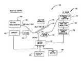
- FIG. 1illustrates one embodiment of a guide wire assembly 20 .
- guide wire assembly 20utilizes optical coherence reflectometry (OCR) to control an RF ablation feature implemented using guide wire assembly 20 .
- OCRoptical coherence reflectometry
- a metal guide wire 24having a cylindrical bore 26 therethrough.
- An optical fiber 28is located within bore 26 of guide wire 24 .
- Guide wire assembly 20is configured to be inserted into a body passage (not shown) such as a blood vessel.
- Guide wire assembly 20further includes an insulation coating 30 extending over guide wire 24 as further described below.
- Guide wire 24has a distal end 32 and a proximal end 34 and optical fiber 28 also includes a distal end 36 and a proximal end 38 .
- distal endrefers to an end first inserted into the body passage and “proximal” refers to an end opposite the “distal end”.
- Distal ends 32 and 36are positioned within a blood vessel (not shown) adjacent tissue through which a guide wire is to be advanced, e.g., plaque (not shown).
- Guide wire 24may be formed, for example, with a coiled wire, as well known in the art.
- Proximal end 34 of guide wire 24is, in one embodiment, configured with an electrical connector 40 , to allow electrical connection of guide wire 24 to an electrical lead 42 .
- Lead 42is attached to guide wire 24 by at least one of soldering, crimping, and welding to proximal end 34 .
- Lead 42is terminated with any standard electrical connector for interfacing with RF generation equipment (shown in FIG. 4 ) used to ablate tissue at distal end 32 of guide wire 24 .
- proximal end 38 of optical fiber 28is configured to be connected to optical equipment 44 , for example an optical coherence reflectometer (OCR) (shown in FIG. 4 ).
- OCRoptical coherence reflectometer
- optical fiber 28into guide wire assembly 20 , along with OCR, provides a control mechanism for the ablation process by providing reflections of the area in front of guide wire 24 . Reflections are used to determine if it is safe to ablate objects, for example, tissue and plaque, within a region. In addition, reflections are used to determine if it is unsafe to ablate objects, for example, healthy tissue (i.e. guide wire 24 is adjacent healthy tissue).
- distal end 38is connected directly to optical equipment 44 . In alternative embodiments, distal end 38 is connected to optical equipment 44 through a series of optical interconnections, as is well known in the art.
- FIG. 2is a sectional view of distal end 52 of guide wire assembly 20 .
- Distal end 32 of guide wire 24 and distal end 36 of optical fiber 28are exposed since insulating coating 30 has been removed at distal end 52 of guide wire assembly 20 .
- about 0.25 to about 0.001 inch of distal end 32 of metal guide wire 24is exposed.
- about 0.1 to about 0.01 inch of distal end 32 of metal guide wire 24is exposed.
- about 0.01 inch of distal end 32 of metal guide wire 24is exposed.
- about 0.1 inch of distal end 32 of metal guide wire 24is exposed.
- insulating coating 30is configured, either through application or removal after application, such that only a cross section of distal end 32 of metal guide wire 24 and distal end 36 of optical fiber 28 are exposed.
- insulating coating 30is one or more of polytetrafluoroethylene (PTFE) material, polyimide, or a conformal coating such as polyparaxylylene (Parylene).
- guide wire assembly 20is a monopolar RF guide wire assembly and is used in conjunction with a grounding plate (shown in FIG. 4 ).
- the grounding platecontacts a patient and provides a return path for RF power transmitted at distal end 32 of metal guide wire 24 during an ablation process.
- FIG. 3is a sectional view of a distal end 102 of a bi-polar guide wire assembly 104 .
- Assembly 104includes an inner guide wire 106 having a bore 108 therethrough from a distal end 110 to a proximal end (not shown).
- An optical fiber 112is within bore 108 of inner guide wire 106 and extends at least from distal end 110 to the proximal end (not shown) of assembly 104 .
- Inner guide wire 106is insulated about its circumference and along its length with an insulating layer 114 .
- insulating coating 114is one or more of polytetrafluoroethylene (PTFE) material, polyimide, epoxy, nylon, rubber or a conformal coating such as polyparaxylylene (Parylene). Insulating layer 114 of a length which prevents electrical contact from occurring between inner guide wire 106 and an outer guide wire 116 .
- Outer guide wire 116includes a bore 118 therethrough from a distal end 120 to a proximal end (not shown).
- optical fiber 112 , inner guide wire 106 , and insulating layer 114are located within bore 118 of outer guide wire 116 .
- Guide wire assembly 104further includes an insulating coating 122 , similar in composition and application to insulating coating 30 (shown in FIG. 2 ), which insulates at least a portion of an outside diameter 124 of outer guide wire 116 .
- Distal end 110 of inner guide wire 106 , distal end 120 of outer guide wire 116 , and distal end 126 of optical fiber 112are exposed as insulating coating 122 has been removed at distal end 102 of guide wire assembly 104 .
- a portion of insulating layer 114is also removed. In one embodiment, from about 0.001 inch to about 0.25 inch of distal ends, 110 and 120 of guide wires 106 and 116 , respectively, are exposed. In another embodiment, from about 0.01 inch to about 0.1 inch of distal ends 110 and 120 of guide wires 106 and 116 , respectively, are exposed.
- insulating coating 122is applied such that only a cross section of distal ends 110 , 120 of guide wires 106 , 116 , an end of insulating layer 114 , and distal end 126 of optical fiber 112 are exposed.
- insulating coating 122is one or more of polytetrafluoroethylene (PTFE) material, polyimide, or a conformal coating such as polyparaxylylene (Parylene).
- Guide wire assembly 104is a bi-polar RF guide wire assembly.
- inner guide wire 106provides a return path for RF power transmitted at distal end 120 of outer guide wire 116 during an ablation process.
- polarity of guide wire assembly 104may be reversed, with outer guide wire 116 providing a return path for RF power and inner guide wire 106 transmitting the RF power.
- insulating coating 122is optional.
- bi-polar guide wire assembly 104has a diameter of at least 0.010 inches.
- Optical fibers 36(shown in FIGS. 1 and 2 ) and 112 are configured to emit energy waves substantially co-axially with respect to the distal ends of guide wire assemblies 20 (shown in FIG. 1 ) and 104 .
- an illumination sourceis a low coherent illumination source, for example, a light emitting diode as known in the art.
- Optical fibers 28 (shown in FIG. 1 ) and 112are fabricated from drawn or extruded glass or plastic having a central core and a cladding of a lower refractive index material to promote internal reflection.
- optical fibers 28 and 112are polarization-preserving single mode optic fibers which preserve the plane of polarization of a light beam as it propagates along the length of a fiber.
- Polarization-preserving optic fibersmaintain the polarization of the light beam by having asymmetry in the fiber structure, either in the overall shape of the fiber, or in the configuration of the cladding with respect to the central core.
- the diameter of each of fibers 28 and 112is about 125 microns, but the diameter may vary.
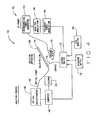
- FIG. 4is a radio frequency (RF) ablation system 150 which incorporates optical coherence reflectometry.
- System 150includes an RF power section 152 , which includes an electrosurgical power generator 154 , a waveform modulator 156 and a frequency power modulator 158 .
- System 150further includes an optical coherence reflectometer 160 whose operation is controlled through computer 162 which has a display 164 .
- Reflectometer 160is optically connected to optical fiber 166 , which extends to proximal ends of fibers 28 and 112 (shown in FIGS. 2 and 3 respectively), which form a portion of guide wire 168 .
- Guide wire 168is in alternative embodiments, one of guide wire assemblies 20 and 104 (described in FIGS. 1 and 3 ).
- a ground plate 170provides a return path for RF power when an embodiment of system 150 incorporates guide wire assembly 20 .
- Electrosurgical power generator 154provides RF power and typically operates with a frequency range of about 200 kHz to about 35 MHz. In the ablation process, a more typical frequency range is about 500 kHz to about 2 MHz. Open circuit voltages range from about 100 V to about 10 kV. Output of generator 154 is waveform modulated so that desired ablation effects are obtained. Coagulation is achieved by using dampened sinusoidal pulses to modulate the RF power at lower frequencies. In one embodiment, the RF output is in a range of about 200 kHz to about 2 MHz and pulsed (modulated) by wave form modulator 156 at a rate of about 100 Hz to about 10 kHz. Cutting (ablation) is achieved through higher RF power output at higher frequencies. In one embodiment, frequencies used for ablation range from about 500 kHz to about 2.5 MHz and an open circuit voltage as high as 1 kV. Although sinusoidal waves are one embodiment of waveform modulation, other waveform modulation patterns are used in alternative embodiments.
- optical fiber 166connects Optical Coherence Reflectometer (OCR) 160 to guide wire 168 to allow visualization of the tissue in front of guide wire 168 .
- OCROptical Coherence Reflectometer
- Low coherence near infrared light from a light emitting diode (not shown)is input into the optical fiber system.
- OCR 160the low coherence light is divided into two beams with one beam being diverted to optical fiber 166 and thus to guide wire 168 .
- the second (reference) beamstays within OCR 160 in a fiber that has a path length equivalent to a path length of the fiber from the OCR 160 , through fiber 166 and guide wire 168 .
- OCR 160is configured in a Michelson interferometer configuration.
- the optical path length in the second (reference) beamis varied, either mechanically by moving a mirror at the end of the fiber within OCR 160 or by stretching the fiber, for example, as is done with PZT stretchers.
- the effectis that the light scattered by the tissue back into guide wire 168 recombines with the light from the second beam such that an interference pattern is generated for light that is scattered from the tissue at an equivalent path length as the second beam.
- an interference intensity versus distance profilecan be generated.
- An algorithmconfigures computer 162 to analyze the scattering intensity versus distance data to determine if there is a sharp increase in the relative scattering within the interferometer sweep. If a sharp increase is detected, the operator is warned that the arterial wall is close and a control signal which enables RF energy output from generator 154 changes state, stopping RF output from generator 154 and therefore stopping delivery of RF energy to guide wire 168 .
- output of generator 154is frequency power modulated to deliver bursts of RF power followed by deadtime, thereby allowing any heat present near the ablation area to dissipate. Utilization of deadtime prevents heat buildup that could damage adjacent tissue.
- RF power output of generator 154is gated by different logical controls.
- a control switch 172provides the gating for the different controls.
- a first gating mechanismis an OCR signal received over optical fiber 166 at OCR 160 .
- the OCR signalis a feedback signal which is monitored through utilization of computer 162 .
- Computer 162also provides a gating signal to control switch 172 , controlling RF output over an electrical contact 174 to assure that a distal tip 176 of guide wire 168 contacts tissue to be ablated.
- the OCR signalis further monitored to assure that an interface between unhealthy and healthy tissue is not near distal tip 176 thus assuring that the ablation will only affect unhealthy (targeted) tissue.
- the OCR signalis monitored to assure that the normal artery wall (media) is not near, whereas in a percutaneous transmyocardial revascularization (PTMR) procedure the OCR signal is monitored for an epicardium interface while myocardial tissue is being ablated.
- the OCR signalwhich is monitored utilizing an algorithm running in computer 162 , yields a go/no-go signal for gating the RF power.
- RF power output transferred to distal tip 176 through electrical contact 174is controlled using an operator switch 178 .
- operator switch 178is a foot switch or any switch accessible by an operator.
- control of the RF power applied for ablation by an operatoris contemplated.
- switch 178is integrated into a catheter handle (not shown) which is utilized for advancement of guide wire 168 . In such an embodiment, when the operator advances guide wire 168 , switch 178 closes allowing the RF power to ablate with the advancement.
- control switch 172is gated by incorporation of an EKG monitor 180 to assure that RF power is not applied during the S-T segment period.
- the heartis most sensitive to electrical stimulation during this time and by blocking RF output during this period, a patient is protected from arrhythmias.
- computer 162is configured to generate data from the ablation process and display the data on display 164 , thereby providing an operator feedback regarding an ablation process.
- RF ablation system 150with incorporation of OCR guidance has many applications in medical practice.
- System 150can be used wherever a conventional guide wire is used, but offers the additional features of tissue ablation and guidance.
- tissue ablation and guidanceIt will be appreciated that the examples described below are not limiting, but rather, the examples are for purposes of illustration.
- atherosclerotic diseaseseverely impairs the arterial functions with the formation of plaques, atheromas, and thrombus in the vessel. This disease is routinely treated by interventional angioplasty.
- traditional guide wiresare threaded through the diseased artery segments by percutaneous introduction through a body extremity.
- Angioplasty balloons or other atherectomy devicesare used to dilate and re-establish flow within the artery.
- guide wire 168is used to cross highly resistant lesions. OCR guidance assures the operator that guide wire 168 is within the lumen and RF ablation provides a hole within the lesions for the wire to pass through. The operator identifies diseased artery segments under angiographic examination with x-ray imaging and the introduction of contrast into the blood field. Commercially available introducers and guide catheters are then used to establish access to the diseased region. The OCR/RF guide wire 168 of system 150 is guided to the targeted segment under x-ray imaging and placed adjacent the diseased blockage.
- the operatorattempts to push guide wire 168 into the lesion using the OCR signal to assure that the wire is within the lumen and not too close to the normal artery wall. If the lesion is too resistant, wire 168 will buckle or the supporting catheter will be forced back (proximal), rather than guide wire 168 advancing. In such a case, the operator selects the RF ablation mode.
- the OCR processing in computer 162assures that distal tip 176 of guide wire 168 is against tissue and that the artery wall is not too close. If necessary, the patient's EKG is monitored with monitor 180 to trigger the RF power during a non-critical time of the coronary cycle. Distal tip 176 , when energized, will create a small spark ablating the tissue in front of the wire.
- the energyis pulsed, as described above, to allow generated heat to dissipate, preventing collateral tissue damage from excessive heat storage.
- the processis repeated to create a hole through the lesion through which wire 168 can pass. If the OCR signal detects a normal artery wall, RF power is removed to prevent damage to the artery.
- Transmyocardial revascularizationis a recent therapy for patients that have severe angina and other treatment modalities have failed. Small channels are ablated into the myocardium to revascularize the ischemic tissue.
- the OCR/RF guide wire system 150is used to create the channels or holes within the myorcardial tissue. Catheters are used to gain percutaneous access to the left ventricle of the heart. Guide wire 168 is introduced through the catheter and positioned adjacent to the inner wall surface. Wire 168 is positioned by x-ray imaging, and advanced into the tissue while energized, ablating a hole.
- the OCR signalis used to control the depth of the hole. Ablation is stopped when the interface between the myocardium and epicardium is approached, preventing perforation of the heart. The OCR signal is also used to prevent perforation of a coronary artery.
- OCR/RF guide wire system 150provides a safe method for advancement of guide wire 168 into a vessel.
- Guide wire 168further is a mechanism which provides information to help an operator distinguish among the types of obstructions which might be obstructing advancement of the guide wire.
- guide wire 168may be made with a harder and less flexible distal end (for example, made of hardened steel) to make it more suitable to go through a partially occluded artery.
- the guide wiremay also be coated with a friction reducing material such as, for example, a polymer or a hydrophilic coating as known in the art.
- the coatingreduces the surface friction to ease advancing the guide wire further into the vessel.
- the guide wiremay also include a thin metal wire positioned next to the fiber optic which can be pulled back making the guide wire end very floppy. The metal wire, when extended, stiffens the distal end portion of the guide wire.
Landscapes
- Health & Medical Sciences (AREA)
- Surgery (AREA)
- Life Sciences & Earth Sciences (AREA)
- Engineering & Computer Science (AREA)
- Heart & Thoracic Surgery (AREA)
- Animal Behavior & Ethology (AREA)
- Otolaryngology (AREA)
- Plasma & Fusion (AREA)
- Physics & Mathematics (AREA)
- Biomedical Technology (AREA)
- Cardiology (AREA)
- Medical Informatics (AREA)
- Molecular Biology (AREA)
- Nuclear Medicine, Radiotherapy & Molecular Imaging (AREA)
- General Health & Medical Sciences (AREA)
- Public Health (AREA)
- Veterinary Medicine (AREA)
- Surgical Instruments (AREA)
- Laser Surgery Devices (AREA)
- Materials For Medical Uses (AREA)
- Mechanical Coupling Of Light Guides (AREA)
Abstract
Description
Claims (20)
Priority Applications (12)
| Application Number | Priority Date | Filing Date | Title |
|---|---|---|---|
| US10/166,900US6852109B2 (en) | 2002-06-11 | 2002-06-11 | Radio frequency guide wire assembly with optical coherence reflectometry guidance |
| DE10392791TDE10392791T5 (en) | 2002-06-11 | 2003-04-23 | High frequency guidewire assembly with guidance by optical coherence reflectance measurement |
| GB0515470AGB2414679B (en) | 2002-06-11 | 2003-04-23 | Radio frequency guide wire assembly with optical coherence reflecometry guidance |
| JP2004510645AJP4455990B2 (en) | 2002-06-11 | 2003-04-23 | High frequency guidewire assembly with guidance by optical interference reflectometry |
| GB0425849AGB2405797B (en) | 2002-06-11 | 2003-04-23 | Radio frequency guide wire assembly with optical coherence reflectometry guidance |
| NZ536759ANZ536759A (en) | 2002-06-11 | 2003-04-23 | Radio frequency guide wire assembly with optical coherence reflectometry guidance |
| CA002487020ACA2487020A1 (en) | 2002-06-11 | 2003-04-23 | Radio frequency guide wire assembly with optical coherence reflectometry guidance |
| AU2003228650AAU2003228650A1 (en) | 2002-06-11 | 2003-04-23 | Radio frequency guide wire assembly with optical coherence reflectometry guidance |
| BR0311734-0ABR0311734A (en) | 2002-06-11 | 2003-04-23 | Guidewire installation, radiofrequency ablation apparatus, and methods for controlling an ablation process using a radiofrequency ablation system and for performing a transmyocardial revascularization procedure using a radiofrequency ablation system |
| HK05103601.0AHK1070802B (en) | 2002-06-11 | 2003-04-23 | Radio frequency guide wire assembly with optical coherence reflectometry guidance |
| PCT/US2003/012483WO2003103520A1 (en) | 2002-06-11 | 2003-04-23 | Radio frequency guide wire assembly with optical coherence reflectometry guidance |
| US10/911,911US7563262B2 (en) | 2002-06-11 | 2004-08-05 | Radio frequency guide wire assembly with optical coherence reflectometry guidance |
Applications Claiming Priority (1)
| Application Number | Priority Date | Filing Date | Title |
|---|---|---|---|
| US10/166,900US6852109B2 (en) | 2002-06-11 | 2002-06-11 | Radio frequency guide wire assembly with optical coherence reflectometry guidance |
Related Child Applications (1)
| Application Number | Title | Priority Date | Filing Date |
|---|---|---|---|
| US10/911,911DivisionUS7563262B2 (en) | 2002-06-11 | 2004-08-05 | Radio frequency guide wire assembly with optical coherence reflectometry guidance |
Publications (2)
| Publication Number | Publication Date |
|---|---|
| US20030229342A1 US20030229342A1 (en) | 2003-12-11 |
| US6852109B2true US6852109B2 (en) | 2005-02-08 |
Family
ID=29710748
Family Applications (2)
| Application Number | Title | Priority Date | Filing Date |
|---|---|---|---|
| US10/166,900Expired - LifetimeUS6852109B2 (en) | 2002-06-11 | 2002-06-11 | Radio frequency guide wire assembly with optical coherence reflectometry guidance |
| US10/911,911Expired - Fee RelatedUS7563262B2 (en) | 2002-06-11 | 2004-08-05 | Radio frequency guide wire assembly with optical coherence reflectometry guidance |
Family Applications After (1)
| Application Number | Title | Priority Date | Filing Date |
|---|---|---|---|
| US10/911,911Expired - Fee RelatedUS7563262B2 (en) | 2002-06-11 | 2004-08-05 | Radio frequency guide wire assembly with optical coherence reflectometry guidance |
Country Status (9)
| Country | Link |
|---|---|
| US (2) | US6852109B2 (en) |
| JP (1) | JP4455990B2 (en) |
| AU (1) | AU2003228650A1 (en) |
| BR (1) | BR0311734A (en) |
| CA (1) | CA2487020A1 (en) |
| DE (1) | DE10392791T5 (en) |
| GB (1) | GB2405797B (en) |
| NZ (1) | NZ536759A (en) |
| WO (1) | WO2003103520A1 (en) |
Cited By (109)
| Publication number | Priority date | Publication date | Assignee | Title |
|---|---|---|---|---|
| US20060036164A1 (en)* | 2001-06-19 | 2006-02-16 | The Trustees Of The University Of Pennsylvania | Optically guided system for precise placement of a medical catheter in a patient |
| US20060200049A1 (en)* | 2005-03-04 | 2006-09-07 | Giovanni Leo | Medical apparatus system having optical fiber load sensing capability |
| US20070060847A1 (en)* | 2005-03-04 | 2007-03-15 | Giovanni Leo | Medical apparatus system having optical fiber load sensing capability |
| US20070123964A1 (en)* | 2003-01-21 | 2007-05-31 | Baylis Medical Company | Magnetically guidable energy delivery apparatus and method of using same |
| US7273056B2 (en) | 2001-06-19 | 2007-09-25 | The Trustees Of The University Of Pennsylvania | Optical guidance system for invasive catheter placement |
| WO2007100629A3 (en)* | 2006-02-22 | 2007-12-27 | Custom Med Applications Inc | Ablation instruments and related methods |
| US20080009750A1 (en)* | 2006-06-09 | 2008-01-10 | Endosense Sa | Catheter having tri-axial force sensor |
| US20080039830A1 (en)* | 2006-08-14 | 2008-02-14 | Munger Gareth T | Method and Apparatus for Ablative Recanalization of Blocked Vasculature |
| US20080039715A1 (en)* | 2004-11-04 | 2008-02-14 | Wilson David F | Three-dimensional optical guidance for catheter placement |
| US20080058789A1 (en)* | 2006-09-06 | 2008-03-06 | Cardiofirst | Guidance system used in treating chronic occlusion |
| US20080097298A1 (en)* | 2006-08-18 | 2008-04-24 | Fisher William T | Catheter for conducting a procedure within a lumen, duct or organ of a living being |
| US20080194973A1 (en)* | 2005-09-13 | 2008-08-14 | Imam Farhad B | Light-guided transluminal catheter |
| US20080253522A1 (en)* | 2007-04-11 | 2008-10-16 | Searete Llc, A Limited Liability Corporation Of The State Of Delaware | Tool associated with compton scattered X-ray visualization, imaging, or information provider |
| US20080253524A1 (en)* | 2007-04-11 | 2008-10-16 | Searete Llc, A Limited Liability Corporation Of The State Of Delaware | Method and system for Compton scattered X-ray depth visualization, imaging, or information provider |
| US20080253528A1 (en)* | 2007-04-11 | 2008-10-16 | Searete Llc, A Limited Liability Corporation Of The State Of Delaware | Low invasive technique using compton scattered x-ray visualizing, imaging, or information providing to differentiate at least some dissimilar matter |
| US20080253527A1 (en)* | 2007-04-11 | 2008-10-16 | Searete Llc, A Limited Liability Corporation Of The State Of Delaware | Limiting compton scattered x-ray visualizing, imaging, or information providing at particular regions |
| US20080294144A1 (en)* | 2007-05-24 | 2008-11-27 | Giovanni Leo | Touch Sensing Catheter |
| US20090030312A1 (en)* | 2007-07-27 | 2009-01-29 | Andreas Hadjicostis | Image-guided intravascular therapy catheters |
| WO2009050478A1 (en) | 2007-10-19 | 2009-04-23 | Barts And The London Nhs Trust | Catheter apparatus |
| US20090287092A1 (en)* | 2008-05-14 | 2009-11-19 | Giovanni Leo | Temperature compensated strain sensing catheter |
| US20100125253A1 (en)* | 2008-11-17 | 2010-05-20 | Avinger | Dual-tip Catheter System for Boring through Blocked Vascular Passages |
| US20100217275A1 (en)* | 2006-11-27 | 2010-08-26 | Ran Carmeli | Device for inducing vibrations in a guidewire |
| US20100305452A1 (en)* | 2009-05-28 | 2010-12-02 | Black John F | Optical coherence tomography for biological imaging |
| US20110004107A1 (en)* | 2009-07-01 | 2011-01-06 | Rosenthal Michael H | Atherectomy catheter with laterally-displaceable tip |
| US20110021926A1 (en)* | 2009-07-01 | 2011-01-27 | Spencer Maegan K | Catheter-based off-axis optical coherence tomography imaging system |
| US8062316B2 (en) | 2008-04-23 | 2011-11-22 | Avinger, Inc. | Catheter system and method for boring through blocked vascular passages |
| US8078261B2 (en) | 2005-09-13 | 2011-12-13 | Children's Medical Center Corporation | Light-guided transluminal catheter |
| US8548571B2 (en) | 2009-12-08 | 2013-10-01 | Avinger, Inc. | Devices and methods for predicting and preventing restenosis |
| US8567265B2 (en) | 2006-06-09 | 2013-10-29 | Endosense, SA | Triaxial fiber optic force sensing catheter |
| US8622935B1 (en) | 2007-05-25 | 2014-01-07 | Endosense Sa | Elongated surgical manipulator with body position and distal force sensing |
| US8644913B2 (en) | 2011-03-28 | 2014-02-04 | Avinger, Inc. | Occlusion-crossing devices, imaging, and atherectomy devices |
| US8696695B2 (en) | 2009-04-28 | 2014-04-15 | Avinger, Inc. | Guidewire positioning catheter |
| US8894589B2 (en) | 2005-08-01 | 2014-11-25 | Endosense Sa | Medical apparatus system having optical fiber load sensing capability |
| US20140378961A1 (en)* | 2013-06-20 | 2014-12-25 | Erbe Elektromedizin Gmbh | Surgical instrument with tissue recognition |
| US9014786B2 (en) | 2005-05-11 | 2015-04-21 | Eyoca Medical Ltd. | Device and method for opening vascular obstructions |
| US9345398B2 (en) | 2012-05-14 | 2016-05-24 | Avinger, Inc. | Atherectomy catheter drive assemblies |
| US9345510B2 (en) | 2010-07-01 | 2016-05-24 | Avinger, Inc. | Atherectomy catheters with longitudinally displaceable drive shafts |
| US9345406B2 (en) | 2011-11-11 | 2016-05-24 | Avinger, Inc. | Occlusion-crossing devices, atherectomy devices, and imaging |
| US9498247B2 (en) | 2014-02-06 | 2016-11-22 | Avinger, Inc. | Atherectomy catheters and occlusion crossing devices |
| US9557156B2 (en) | 2012-05-14 | 2017-01-31 | Avinger, Inc. | Optical coherence tomography with graded index fiber for biological imaging |
| US9592075B2 (en) | 2014-02-06 | 2017-03-14 | Avinger, Inc. | Atherectomy catheters devices having multi-channel bushings |
| US9854979B2 (en) | 2013-03-15 | 2018-01-02 | Avinger, Inc. | Chronic total occlusion crossing devices with imaging |
| US9949754B2 (en) | 2011-03-28 | 2018-04-24 | Avinger, Inc. | Occlusion-crossing devices |
| US10130386B2 (en) | 2013-07-08 | 2018-11-20 | Avinger, Inc. | Identification of elastic lamina to guide interventional therapy |
| US10188368B2 (en) | 2017-06-26 | 2019-01-29 | Andreas Hadjicostis | Image guided intravascular therapy catheter utilizing a thin chip multiplexor |
| US10258240B1 (en) | 2014-11-24 | 2019-04-16 | Vascular Imaging Corporation | Optical fiber pressure sensor |
| US10327645B2 (en) | 2013-10-04 | 2019-06-25 | Vascular Imaging Corporation | Imaging techniques using an imaging guidewire |
| US10335173B2 (en) | 2012-09-06 | 2019-07-02 | Avinger, Inc. | Re-entry stylet for catheter |
| US10357277B2 (en) | 2014-07-08 | 2019-07-23 | Avinger, Inc. | High speed chronic total occlusion crossing devices |
| US10363062B2 (en) | 2011-10-17 | 2019-07-30 | Avinger, Inc. | Atherectomy catheters and non-contact actuation mechanism for catheters |
| US10492760B2 (en) | 2017-06-26 | 2019-12-03 | Andreas Hadjicostis | Image guided intravascular therapy catheter utilizing a thin chip multiplexor |
| US10506934B2 (en) | 2012-05-25 | 2019-12-17 | Phyzhon Health Inc. | Optical fiber pressure sensor |
| US10537255B2 (en) | 2013-11-21 | 2020-01-21 | Phyzhon Health Inc. | Optical fiber pressure sensor |
| US10548478B2 (en) | 2010-07-01 | 2020-02-04 | Avinger, Inc. | Balloon atherectomy catheters with imaging |
| US10561368B2 (en) | 2011-04-14 | 2020-02-18 | St. Jude Medical International Holding S.À R.L. | Compact force sensor for catheters |
| US10568520B2 (en) | 2015-07-13 | 2020-02-25 | Avinger, Inc. | Micro-molded anamorphic reflector lens for image guided therapeutic/diagnostic catheters |
| US10772683B2 (en) | 2014-05-18 | 2020-09-15 | Eximo Medical Ltd. | System for tissue ablation using pulsed laser |
| US10932670B2 (en) | 2013-03-15 | 2021-03-02 | Avinger, Inc. | Optical pressure sensor assembly |
| US11096717B2 (en) | 2013-03-15 | 2021-08-24 | Avinger, Inc. | Tissue collection device for catheter |
| US11109909B1 (en) | 2017-06-26 | 2021-09-07 | Andreas Hadjicostis | Image guided intravascular therapy catheter utilizing a thin ablation electrode |
| US11224459B2 (en) | 2016-06-30 | 2022-01-18 | Avinger, Inc. | Atherectomy catheter with shapeable distal tip |
| US11278248B2 (en) | 2016-01-25 | 2022-03-22 | Avinger, Inc. | OCT imaging catheter with lag correction |
| US11284916B2 (en) | 2012-09-06 | 2022-03-29 | Avinger, Inc. | Atherectomy catheters and occlusion crossing devices |
| US11344327B2 (en) | 2016-06-03 | 2022-05-31 | Avinger, Inc. | Catheter device with detachable distal end |
| US11382653B2 (en) | 2010-07-01 | 2022-07-12 | Avinger, Inc. | Atherectomy catheter |
| US11399863B2 (en) | 2016-04-01 | 2022-08-02 | Avinger, Inc. | Atherectomy catheter with serrated cutter |
| US11406412B2 (en) | 2012-05-14 | 2022-08-09 | Avinger, Inc. | Atherectomy catheters with imaging |
| US11445937B2 (en) | 2016-01-07 | 2022-09-20 | St. Jude Medical International Holding S.À R.L. | Medical device with multi-core fiber for optical sensing |
| US11576724B2 (en) | 2011-02-24 | 2023-02-14 | Eximo Medical Ltd. | Hybrid catheter for vascular intervention |
| US11660137B2 (en) | 2006-09-29 | 2023-05-30 | Boston Scientific Medical Device Limited | Connector system for electrosurgical device |
| US11684447B2 (en) | 2012-05-31 | 2023-06-27 | Boston Scientific Medical Device Limited | Radiofrequency perforation apparatus |
| US11684420B2 (en) | 2016-05-05 | 2023-06-27 | Eximo Medical Ltd. | Apparatus and methods for resecting and/or ablating an undesired tissue |
| US11724070B2 (en) | 2019-12-19 | 2023-08-15 | Boston Scientific Medical Device Limited | Methods for determining a position of a first medical device with respect to a second medical device, and related systems and medical devices |
| US11744638B2 (en) | 2006-09-29 | 2023-09-05 | Boston Scientific Medical Device Limited | Electrosurgical device |
| US11759190B2 (en) | 2019-10-18 | 2023-09-19 | Boston Scientific Medical Device Limited | Lock for medical devices, and related systems and methods |
| US11766290B2 (en) | 2015-09-09 | 2023-09-26 | Boston Scientific Medical Device Limited | Epicardial access system and methods |
| US11793446B2 (en) | 2020-06-17 | 2023-10-24 | Boston Scientific Medical Device Limited | Electroanatomical mapping system with visualization of energy-delivery and elongated needle assemblies |
| US11793400B2 (en) | 2019-10-18 | 2023-10-24 | Avinger, Inc. | Occlusion-crossing devices |
| US11801087B2 (en) | 2019-11-13 | 2023-10-31 | Boston Scientific Medical Device Limited | Apparatus and methods for puncturing tissue |
| US11819243B2 (en) | 2020-03-19 | 2023-11-21 | Boston Scientific Medical Device Limited | Medical sheath and related systems and methods |
| US11826075B2 (en) | 2020-04-07 | 2023-11-28 | Boston Scientific Medical Device Limited | Elongated medical assembly |
| US11878131B2 (en) | 2017-12-05 | 2024-01-23 | Boston Scientific Medical Device Limited | Transseptal guide wire puncture system |
| US11931098B2 (en) | 2020-02-19 | 2024-03-19 | Boston Scientific Medical Device Limited | System and method for carrying out a medical procedure |
| US11937873B2 (en) | 2013-03-12 | 2024-03-26 | Boston Scientific Medical Device Limited | Electrosurgical device having a lumen |
| US11937796B2 (en) | 2020-06-18 | 2024-03-26 | Boston Scientific Medical Device Limited | Tissue-spreader assembly |
| US11938285B2 (en) | 2020-06-17 | 2024-03-26 | Boston Scientific Medical Device Limited | Stop-movement device for elongated medical assembly |
| US11980412B2 (en) | 2020-09-15 | 2024-05-14 | Boston Scientific Medical Device Limited | Elongated medical sheath |
| US11986209B2 (en) | 2020-02-25 | 2024-05-21 | Boston Scientific Medical Device Limited | Methods and devices for creation of communication between aorta and left atrium |
| US11998238B2 (en) | 2013-08-07 | 2024-06-04 | Boston Scientific Medical Device Limited | Methods and devices for puncturing tissue |
| US12005202B2 (en) | 2020-08-07 | 2024-06-11 | Boston Scientific Medical Device Limited | Catheter having tissue-engaging device |
| US12011279B2 (en) | 2020-04-07 | 2024-06-18 | Boston Scientific Medical Device Limited | Electro-anatomic mapping system |
| US12011210B2 (en) | 2013-03-15 | 2024-06-18 | Boston Scientific Medical Device Limited | Electrosurgical device having a distal aperture |
| US12038322B2 (en) | 2022-06-21 | 2024-07-16 | Eximo Medical Ltd. | Devices and methods for testing ablation systems |
| US12042178B2 (en) | 2020-07-21 | 2024-07-23 | Boston Scientific Medical Device Limited | System of medical devices and method for pericardial puncture |
| US12082792B2 (en) | 2020-02-25 | 2024-09-10 | Boston Scientific Medical Device Limited | Systems and methods for creating a puncture between aorta and the left atrium |
| US12128199B2 (en) | 2016-01-07 | 2024-10-29 | Boston Scientific Medical Device Limited | Hybrid transseptal dilator and methods of using the same |
| US12156642B2 (en) | 2019-04-29 | 2024-12-03 | Boston Scientific Medical Device Limited | Transseptal systems, devices and methods |
| US12167867B2 (en) | 2018-04-19 | 2024-12-17 | Avinger, Inc. | Occlusion-crossing devices |
| US12171622B2 (en) | 2017-08-10 | 2024-12-24 | Boston Scientific Medical Device Limited | Heat exchange and temperature sensing device and method of use |
| US12207836B2 (en) | 2016-11-01 | 2025-01-28 | Boston Scientific Medical Device Limited | Methods and devices for puncturing tissue |
| US12220543B2 (en) | 2020-09-10 | 2025-02-11 | Boston Scientific Medical Device Limited | Elongated medical catheter including marker band |
| US12251159B2 (en) | 2013-03-12 | 2025-03-18 | Boston Scientific Medical Device Limited | Medical device having a support structure |
| US12257401B2 (en) | 2013-12-20 | 2025-03-25 | Boston Scientific Medical Device Limited | Steerable medical device handle |
| US12343042B2 (en) | 2020-07-16 | 2025-07-01 | Boston Scientific Medical Device Limited | Pericardial puncture device and method |
| US12370354B2 (en) | 2018-05-08 | 2025-07-29 | Boston Scientific Medical Device Limited | Coupling mechanisms for medical devices |
| US12376904B1 (en) | 2020-09-08 | 2025-08-05 | Angiodynamics, Inc. | Dynamic laser stabilization and calibration system |
| US12396785B2 (en) | 2020-08-12 | 2025-08-26 | Boston Scientific Medical Device Limited | System of medical devices and method for pericardial puncture |
| US12420067B2 (en) | 2020-05-12 | 2025-09-23 | Boston Scientific Medical Device Limited | Guidewire assembly |
| US12440266B2 (en) | 2022-04-08 | 2025-10-14 | Boston Scientific Medical Device Limited | Transvascular electrosurgical devices and systems and methods of using the same |
Families Citing this family (19)
| Publication number | Priority date | Publication date | Assignee | Title |
|---|---|---|---|---|
| DE202004021953U1 (en)* | 2003-09-12 | 2013-06-19 | Vessix Vascular, Inc. | Selectable eccentric remodeling and / or ablation of atherosclerotic material |
| US20050135763A1 (en)* | 2003-12-17 | 2005-06-23 | Gary Drenzek | Optical fiber with a mechanically strippable coating and methods of making the same |
| US8396548B2 (en) | 2008-11-14 | 2013-03-12 | Vessix Vascular, Inc. | Selective drug delivery in a lumen |
| US7417740B2 (en)* | 2004-11-12 | 2008-08-26 | Medeikon Corporation | Single trace multi-channel low coherence interferometric sensor |
| EP2438877B1 (en) | 2005-03-28 | 2016-02-17 | Vessix Vascular, Inc. | Intraluminal electrical tissue characterization and tuned RF energy for selective treatment of atheroma and other target tissues |
| JP5559539B2 (en) | 2006-10-18 | 2014-07-23 | べシックス・バスキュラー・インコーポレイテッド | System that induces desirable temperature effects on body tissue |
| EP2076198A4 (en)* | 2006-10-18 | 2009-12-09 | Minnow Medical Inc | Inducing desirable temperature effects on body tissue |
| EP2455036B1 (en)* | 2006-10-18 | 2015-07-15 | Vessix Vascular, Inc. | Tuned RF energy and electrical tissue characterization for selective treatment of target tissues |
| US8496653B2 (en)* | 2007-04-23 | 2013-07-30 | Boston Scientific Scimed, Inc. | Thrombus removal |
| EP2341839B1 (en)* | 2008-09-22 | 2015-10-21 | Vessix Vascular, Inc. | System for vascular ultrasound treatments |
| EP2355737B1 (en) | 2008-11-17 | 2021-08-11 | Boston Scientific Scimed, Inc. | Selective accumulation of energy without knowledge of tissue topography |
| US8551096B2 (en) | 2009-05-13 | 2013-10-08 | Boston Scientific Scimed, Inc. | Directional delivery of energy and bioactives |
| WO2011126580A2 (en) | 2010-04-09 | 2011-10-13 | Minnow Medical, Inc. | Power generating and control apparatus for the treatment of tissue |
| CN101947132A (en)* | 2010-09-29 | 2011-01-19 | 南京航空航天大学 | Probe of radio frequency therapeutic apparatus |
| EP3284430B1 (en) | 2012-05-02 | 2023-08-02 | Erbe Elektromedizin GmbH | Electrosurgical apparatus with means for producing a light appearance and for differentiating between tissues through light analysis |
| US11779390B2 (en) | 2018-12-26 | 2023-10-10 | Biosense Webster (Israel) Ltd. | Pericardium catheter including camera for guiding cutting through pericardium |
| EP3685781B8 (en)* | 2019-01-24 | 2022-06-29 | Erbe Elektromedizin GmbH | Device for tissue coagulation |
| EP4190228A1 (en) | 2021-12-03 | 2023-06-07 | Erbe Elektromedizin GmbH | Device for tissue identification |
| WO2024185773A1 (en)* | 2023-03-08 | 2024-09-12 | 古河電気工業株式会社 | Laser light irradiation device |
Citations (20)
| Publication number | Priority date | Publication date | Assignee | Title |
|---|---|---|---|---|
| US3595239A (en) | 1969-04-04 | 1971-07-27 | Roy A Petersen | Catheter with electrical cutting means |
| US4532924A (en) | 1980-05-13 | 1985-08-06 | American Hospital Supply Corporation | Multipolar electrosurgical device and method |
| US4682596A (en) | 1984-05-22 | 1987-07-28 | Cordis Corporation | Electrosurgical catheter and method for vascular applications |
| US5098431A (en) | 1989-04-13 | 1992-03-24 | Everest Medical Corporation | RF ablation catheter |
| US5321501A (en)* | 1991-04-29 | 1994-06-14 | Massachusetts Institute Of Technology | Method and apparatus for optical imaging with means for controlling the longitudinal range of the sample |
| US5439000A (en)* | 1992-11-18 | 1995-08-08 | Spectrascience, Inc. | Method of diagnosing tissue with guidewire |
| US5454809A (en) | 1989-01-06 | 1995-10-03 | Angioplasty Systems, Inc. | Electrosurgical catheter and method for resolving atherosclerotic plaque by radio frequency sparking |
| US5514128A (en)* | 1992-08-18 | 1996-05-07 | Spectranetics Corporation | Fiber optic guide wire and support catheter therefor |
| US5722403A (en)* | 1996-10-28 | 1998-03-03 | Ep Technologies, Inc. | Systems and methods using a porous electrode for ablating and visualizing interior tissue regions |
| US5743900A (en) | 1995-06-06 | 1998-04-28 | Sun Star Technology, Inc. | Hot tip catheter and method for using the same |
| US5749914A (en) | 1989-01-06 | 1998-05-12 | Advanced Coronary Intervention | Catheter for obstructed stent |
| US5762609A (en)* | 1992-09-14 | 1998-06-09 | Sextant Medical Corporation | Device and method for analysis of surgical tissue interventions |
| US5782826A (en)* | 1996-11-01 | 1998-07-21 | Ep Technologies, Inc. | System and methods for detecting ancillary tissue near tissue targeted for ablation |
| US6117128A (en)* | 1997-04-30 | 2000-09-12 | Kenton W. Gregory | Energy delivery catheter and method for the use thereof |
| US6175669B1 (en)* | 1998-03-30 | 2001-01-16 | The Regents Of The Universtiy Of California | Optical coherence domain reflectometry guidewire |
| US6193676B1 (en) | 1997-10-03 | 2001-02-27 | Intraluminal Therapeutics, Inc. | Guide wire assembly |
| US6228081B1 (en)* | 1999-05-21 | 2001-05-08 | Gyrus Medical Limited | Electrosurgery system and method |
| US6458088B1 (en)* | 1997-03-27 | 2002-10-01 | Cordis Corporation | Glass core guidewire compatible with magnetic resonance |
| US6485488B1 (en)* | 1997-09-17 | 2002-11-26 | Laser-Und Medizin-Technologies Gmbh Berlin | Device for revascularizing muscular tissues |
| US6660001B2 (en) | 2000-01-21 | 2003-12-09 | Providence Health System-Oregon | Myocardial revascularization-optical reflectance catheter and method |
Family Cites Families (4)
| Publication number | Priority date | Publication date | Assignee | Title |
|---|---|---|---|---|
| US5178620A (en)* | 1988-06-10 | 1993-01-12 | Advanced Angioplasty Products, Inc. | Thermal dilatation catheter and method |
| US5752518A (en)* | 1996-10-28 | 1998-05-19 | Ep Technologies, Inc. | Systems and methods for visualizing interior regions of the body |
| EP1292214A4 (en)* | 2000-05-19 | 2007-07-04 | Bard Inc C R | Guidewire with viewing capability |
| JP4222775B2 (en)* | 2001-06-15 | 2009-02-12 | ラディ・メディカル・システムズ・アクチェボラーグ | Measuring device that can be inserted into living organisms |
- 2002
- 2002-06-11USUS10/166,900patent/US6852109B2/ennot_activeExpired - Lifetime
- 2003
- 2003-04-23CACA002487020Apatent/CA2487020A1/ennot_activeAbandoned
- 2003-04-23AUAU2003228650Apatent/AU2003228650A1/ennot_activeAbandoned
- 2003-04-23NZNZ536759Apatent/NZ536759A/enunknown
- 2003-04-23DEDE10392791Tpatent/DE10392791T5/ennot_activeWithdrawn
- 2003-04-23JPJP2004510645Apatent/JP4455990B2/ennot_activeExpired - Fee Related
- 2003-04-23GBGB0425849Apatent/GB2405797B/ennot_activeExpired - Fee Related
- 2003-04-23WOPCT/US2003/012483patent/WO2003103520A1/enactiveApplication Filing
- 2003-04-23BRBR0311734-0Apatent/BR0311734A/ennot_activeIP Right Cessation
- 2004
- 2004-08-05USUS10/911,911patent/US7563262B2/ennot_activeExpired - Fee Related
Patent Citations (21)
| Publication number | Priority date | Publication date | Assignee | Title |
|---|---|---|---|---|
| US3595239A (en) | 1969-04-04 | 1971-07-27 | Roy A Petersen | Catheter with electrical cutting means |
| US4532924A (en) | 1980-05-13 | 1985-08-06 | American Hospital Supply Corporation | Multipolar electrosurgical device and method |
| US4682596A (en) | 1984-05-22 | 1987-07-28 | Cordis Corporation | Electrosurgical catheter and method for vascular applications |
| US5749914A (en) | 1989-01-06 | 1998-05-12 | Advanced Coronary Intervention | Catheter for obstructed stent |
| US5454809A (en) | 1989-01-06 | 1995-10-03 | Angioplasty Systems, Inc. | Electrosurgical catheter and method for resolving atherosclerotic plaque by radio frequency sparking |
| US5098431A (en) | 1989-04-13 | 1992-03-24 | Everest Medical Corporation | RF ablation catheter |
| US5321501A (en)* | 1991-04-29 | 1994-06-14 | Massachusetts Institute Of Technology | Method and apparatus for optical imaging with means for controlling the longitudinal range of the sample |
| US5514128A (en)* | 1992-08-18 | 1996-05-07 | Spectranetics Corporation | Fiber optic guide wire and support catheter therefor |
| US5762609A (en)* | 1992-09-14 | 1998-06-09 | Sextant Medical Corporation | Device and method for analysis of surgical tissue interventions |
| US5439000A (en)* | 1992-11-18 | 1995-08-08 | Spectrascience, Inc. | Method of diagnosing tissue with guidewire |
| US5601087A (en)* | 1992-11-18 | 1997-02-11 | Spectrascience, Inc. | System for diagnosing tissue with guidewire |
| US5743900A (en) | 1995-06-06 | 1998-04-28 | Sun Star Technology, Inc. | Hot tip catheter and method for using the same |
| US5722403A (en)* | 1996-10-28 | 1998-03-03 | Ep Technologies, Inc. | Systems and methods using a porous electrode for ablating and visualizing interior tissue regions |
| US5782826A (en)* | 1996-11-01 | 1998-07-21 | Ep Technologies, Inc. | System and methods for detecting ancillary tissue near tissue targeted for ablation |
| US6458088B1 (en)* | 1997-03-27 | 2002-10-01 | Cordis Corporation | Glass core guidewire compatible with magnetic resonance |
| US6117128A (en)* | 1997-04-30 | 2000-09-12 | Kenton W. Gregory | Energy delivery catheter and method for the use thereof |
| US6485488B1 (en)* | 1997-09-17 | 2002-11-26 | Laser-Und Medizin-Technologies Gmbh Berlin | Device for revascularizing muscular tissues |
| US6193676B1 (en) | 1997-10-03 | 2001-02-27 | Intraluminal Therapeutics, Inc. | Guide wire assembly |
| US6175669B1 (en)* | 1998-03-30 | 2001-01-16 | The Regents Of The Universtiy Of California | Optical coherence domain reflectometry guidewire |
| US6228081B1 (en)* | 1999-05-21 | 2001-05-08 | Gyrus Medical Limited | Electrosurgery system and method |
| US6660001B2 (en) | 2000-01-21 | 2003-12-09 | Providence Health System-Oregon | Myocardial revascularization-optical reflectance catheter and method |
Cited By (203)
| Publication number | Priority date | Publication date | Assignee | Title |
|---|---|---|---|---|
| US7992573B2 (en) | 2001-06-19 | 2011-08-09 | The Trustees Of The University Of Pennsylvania | Optically guided system for precise placement of a medical catheter in a patient |
| US7273056B2 (en) | 2001-06-19 | 2007-09-25 | The Trustees Of The University Of Pennsylvania | Optical guidance system for invasive catheter placement |
| US7757695B2 (en) | 2001-06-19 | 2010-07-20 | The Trustees Of The University Of Pennsylvania | Method for catheter placement |
| US20060036164A1 (en)* | 2001-06-19 | 2006-02-16 | The Trustees Of The University Of Pennsylvania | Optically guided system for precise placement of a medical catheter in a patient |
| US20080027408A1 (en)* | 2001-06-19 | 2008-01-31 | The Trustees Of The University Of Pennsylvania | Method for catheter placement |
| US8092450B2 (en) | 2003-01-21 | 2012-01-10 | Baylis Medical Company Inc. | Magnetically guidable energy delivery apparatus and method of using same |
| US20070123964A1 (en)* | 2003-01-21 | 2007-05-31 | Baylis Medical Company | Magnetically guidable energy delivery apparatus and method of using same |
| US20080039715A1 (en)* | 2004-11-04 | 2008-02-14 | Wilson David F | Three-dimensional optical guidance for catheter placement |
| US11998404B2 (en) | 2005-03-04 | 2024-06-04 | St. Jude Medical International Holding S.À R.L. | Medical apparatus system having optical fiber load sensing capability |
| US8075498B2 (en) | 2005-03-04 | 2011-12-13 | Endosense Sa | Medical apparatus system having optical fiber load sensing capability |
| US20060200049A1 (en)* | 2005-03-04 | 2006-09-07 | Giovanni Leo | Medical apparatus system having optical fiber load sensing capability |
| US8182433B2 (en) | 2005-03-04 | 2012-05-22 | Endosense Sa | Medical apparatus system having optical fiber load sensing capability |
| US20070060847A1 (en)* | 2005-03-04 | 2007-03-15 | Giovanni Leo | Medical apparatus system having optical fiber load sensing capability |
| US8961436B2 (en) | 2005-03-04 | 2015-02-24 | St. Jude Medical Luxembourg Holding S.á.r.l. | Medical apparatus system having optical fiber load sensing capability |
| US10973606B2 (en) | 2005-03-04 | 2021-04-13 | St. Jude Medical International Holding S.À R.L. | Medical apparatus system having optical fiber load sensing capability |
| US8932288B2 (en) | 2005-03-04 | 2015-01-13 | Endosense Sa | Medical apparatus system having optical fiber load sensing capability |
| US9907618B2 (en) | 2005-03-04 | 2018-03-06 | St Jude Medical International Holding S.À R.L. | Medical apparatus system having optical fiber sensing capability |
| US9014786B2 (en) | 2005-05-11 | 2015-04-21 | Eyoca Medical Ltd. | Device and method for opening vascular obstructions |
| US8894589B2 (en) | 2005-08-01 | 2014-11-25 | Endosense Sa | Medical apparatus system having optical fiber load sensing capability |
| US8954134B2 (en) | 2005-09-13 | 2015-02-10 | Children's Medical Center Corporation | Light-guided transluminal catheter |
| US20080194973A1 (en)* | 2005-09-13 | 2008-08-14 | Imam Farhad B | Light-guided transluminal catheter |
| US8078261B2 (en) | 2005-09-13 | 2011-12-13 | Children's Medical Center Corporation | Light-guided transluminal catheter |
| US20090187179A1 (en)* | 2006-02-22 | 2009-07-23 | Racz N Sandor | Ablation Instruments and Related Methods |
| WO2007100629A3 (en)* | 2006-02-22 | 2007-12-27 | Custom Med Applications Inc | Ablation instruments and related methods |
| US9265563B2 (en) | 2006-02-22 | 2016-02-23 | Custom Medical Applications, Inc. | Ablation instruments and related methods |
| US8435232B2 (en) | 2006-06-09 | 2013-05-07 | Nicolas Aeby | Catheter having tri-axial force sensor |
| US20080009750A1 (en)* | 2006-06-09 | 2008-01-10 | Endosense Sa | Catheter having tri-axial force sensor |
| US11883131B2 (en) | 2006-06-09 | 2024-01-30 | St. Jude Medical International Holding S.À R.L. | Triaxial fiber optic force sensing catheter |
| US8567265B2 (en) | 2006-06-09 | 2013-10-29 | Endosense, SA | Triaxial fiber optic force sensing catheter |
| US10596346B2 (en) | 2006-06-09 | 2020-03-24 | St. Jude Medical International Holding S.À R.L. | Triaxial fiber optic force sensing catheter |
| US9597036B2 (en) | 2006-06-09 | 2017-03-21 | St. Jude Medical International Holding S.À R.L. | Triaxial fiber optic force sensing catheter and method of use |
| US8048063B2 (en) | 2006-06-09 | 2011-11-01 | Endosense Sa | Catheter having tri-axial force sensor |
| US20080039830A1 (en)* | 2006-08-14 | 2008-02-14 | Munger Gareth T | Method and Apparatus for Ablative Recanalization of Blocked Vasculature |
| US20100228152A1 (en)* | 2006-08-18 | 2010-09-09 | Fisher William T | Catheter for conducting a procedure within a lumen, duct or organ of a living being |
| US8721626B2 (en) | 2006-08-18 | 2014-05-13 | Kensey Nash Corporation | Catheter for conducting a procedure within a lumen, duct or organ of a living being |
| US7674253B2 (en) | 2006-08-18 | 2010-03-09 | Kensey Nash Corporation | Catheter for conducting a procedure within a lumen, duct or organ of a living being |
| US20080097298A1 (en)* | 2006-08-18 | 2008-04-24 | Fisher William T | Catheter for conducting a procedure within a lumen, duct or organ of a living being |
| US20080058789A1 (en)* | 2006-09-06 | 2008-03-06 | Cardiofirst | Guidance system used in treating chronic occlusion |
| US11666377B2 (en) | 2006-09-29 | 2023-06-06 | Boston Scientific Medical Device Limited | Electrosurgical device |
| US11744638B2 (en) | 2006-09-29 | 2023-09-05 | Boston Scientific Medical Device Limited | Electrosurgical device |
| US12161390B2 (en) | 2006-09-29 | 2024-12-10 | Boston Scientific Medical Device Limited | Connector system for electrosurgical device |
| US11660137B2 (en) | 2006-09-29 | 2023-05-30 | Boston Scientific Medical Device Limited | Connector system for electrosurgical device |
| US20100217275A1 (en)* | 2006-11-27 | 2010-08-26 | Ran Carmeli | Device for inducing vibrations in a guidewire |
| US20080253531A1 (en)* | 2007-04-11 | 2008-10-16 | Searete Llc, A Limited Liability Corporation Of The State Of Delaware | Cauterizing based at least partially on Compton scattered x-ray visualizing, imaging, or information providing |
| US20080253527A1 (en)* | 2007-04-11 | 2008-10-16 | Searete Llc, A Limited Liability Corporation Of The State Of Delaware | Limiting compton scattered x-ray visualizing, imaging, or information providing at particular regions |
| US20080253528A1 (en)* | 2007-04-11 | 2008-10-16 | Searete Llc, A Limited Liability Corporation Of The State Of Delaware | Low invasive technique using compton scattered x-ray visualizing, imaging, or information providing to differentiate at least some dissimilar matter |
| US20080253524A1 (en)* | 2007-04-11 | 2008-10-16 | Searete Llc, A Limited Liability Corporation Of The State Of Delaware | Method and system for Compton scattered X-ray depth visualization, imaging, or information provider |
| US20080253522A1 (en)* | 2007-04-11 | 2008-10-16 | Searete Llc, A Limited Liability Corporation Of The State Of Delaware | Tool associated with compton scattered X-ray visualization, imaging, or information provider |
| US20080294144A1 (en)* | 2007-05-24 | 2008-11-27 | Giovanni Leo | Touch Sensing Catheter |
| US8157789B2 (en) | 2007-05-24 | 2012-04-17 | Endosense Sa | Touch sensing catheter |
| US8622935B1 (en) | 2007-05-25 | 2014-01-07 | Endosense Sa | Elongated surgical manipulator with body position and distal force sensing |
| US9993617B1 (en) | 2007-05-25 | 2018-06-12 | St. Jude Medical International Holdings S.À R.L. | Elongated surgical manipulator with body position and distal force sensing |
| US10905855B2 (en) | 2007-05-25 | 2021-02-02 | St. Jude Medical International Holding S.ár.l. | Elongated surgical manipulator with body position and distal force sensing |
| US8702609B2 (en) | 2007-07-27 | 2014-04-22 | Meridian Cardiovascular Systems, Inc. | Image-guided intravascular therapy catheters |
| US20090030312A1 (en)* | 2007-07-27 | 2009-01-29 | Andreas Hadjicostis | Image-guided intravascular therapy catheters |
| WO2009050478A1 (en) | 2007-10-19 | 2009-04-23 | Barts And The London Nhs Trust | Catheter apparatus |
| US10869685B2 (en) | 2008-04-23 | 2020-12-22 | Avinger, Inc. | Catheter system and method for boring through blocked vascular passages |
| US9572492B2 (en) | 2008-04-23 | 2017-02-21 | Avinger, Inc. | Occlusion-crossing devices, imaging, and atherectomy devices |
| US8062316B2 (en) | 2008-04-23 | 2011-11-22 | Avinger, Inc. | Catheter system and method for boring through blocked vascular passages |
| US9918734B2 (en) | 2008-04-23 | 2018-03-20 | Avinger, Inc. | Catheter system and method for boring through blocked vascular passages |
| US8361097B2 (en) | 2008-04-23 | 2013-01-29 | Avinger, Inc. | Catheter system and method for boring through blocked vascular passages |
| US20090287092A1 (en)* | 2008-05-14 | 2009-11-19 | Giovanni Leo | Temperature compensated strain sensing catheter |
| US8298227B2 (en) | 2008-05-14 | 2012-10-30 | Endosense Sa | Temperature compensated strain sensing catheter |
| US20100125253A1 (en)* | 2008-11-17 | 2010-05-20 | Avinger | Dual-tip Catheter System for Boring through Blocked Vascular Passages |
| US9642646B2 (en) | 2009-04-28 | 2017-05-09 | Avinger, Inc. | Guidewire positioning catheter |
| US11998311B2 (en) | 2009-04-28 | 2024-06-04 | Avinger, Inc. | Guidewire positioning catheter |
| US11076773B2 (en) | 2009-04-28 | 2021-08-03 | Avinger, Inc. | Guidewire positioning catheter |
| US8696695B2 (en) | 2009-04-28 | 2014-04-15 | Avinger, Inc. | Guidewire positioning catheter |
| US11839493B2 (en) | 2009-05-28 | 2023-12-12 | Avinger, Inc. | Optical coherence tomography for biological imaging |
| US20100305452A1 (en)* | 2009-05-28 | 2010-12-02 | Black John F | Optical coherence tomography for biological imaging |
| US9788790B2 (en) | 2009-05-28 | 2017-10-17 | Avinger, Inc. | Optical coherence tomography for biological imaging |
| US12178613B2 (en) | 2009-05-28 | 2024-12-31 | Avinger, Inc. | Optical coherence tomography for biological imaging |
| US10342491B2 (en) | 2009-05-28 | 2019-07-09 | Avinger, Inc. | Optical coherence tomography for biological imaging |
| US11284839B2 (en) | 2009-05-28 | 2022-03-29 | Avinger, Inc. | Optical coherence tomography for biological imaging |
| US10052125B2 (en) | 2009-07-01 | 2018-08-21 | Avinger, Inc. | Atherectomy catheter with laterally-displaceable tip |
| US10729326B2 (en) | 2009-07-01 | 2020-08-04 | Avinger, Inc. | Catheter-based off-axis optical coherence tomography imaging system |
| US20110021926A1 (en)* | 2009-07-01 | 2011-01-27 | Spencer Maegan K | Catheter-based off-axis optical coherence tomography imaging system |
| US11717314B2 (en) | 2009-07-01 | 2023-08-08 | Avinger, Inc. | Atherectomy catheter with laterally-displaceable tip |
| US9498600B2 (en) | 2009-07-01 | 2016-11-22 | Avinger, Inc. | Atherectomy catheter with laterally-displaceable tip |
| US12089868B2 (en) | 2009-07-01 | 2024-09-17 | Avinger, Inc. | Methods of using atherectomy catheter with deflectable distal tip |
| US20110004107A1 (en)* | 2009-07-01 | 2011-01-06 | Rosenthal Michael H | Atherectomy catheter with laterally-displaceable tip |
| US9125562B2 (en) | 2009-07-01 | 2015-09-08 | Avinger, Inc. | Catheter-based off-axis optical coherence tomography imaging system |
| US12053260B2 (en) | 2009-07-01 | 2024-08-06 | Avinger, Inc. | Catheter-based off-axis optical coherence tomography imaging system |
| US8548571B2 (en) | 2009-12-08 | 2013-10-01 | Avinger, Inc. | Devices and methods for predicting and preventing restenosis |
| US10349974B2 (en) | 2010-07-01 | 2019-07-16 | Avinger, Inc. | Atherectomy catheters with longitudinally displaceable drive shafts |
| US11382653B2 (en) | 2010-07-01 | 2022-07-12 | Avinger, Inc. | Atherectomy catheter |
| US9345510B2 (en) | 2010-07-01 | 2016-05-24 | Avinger, Inc. | Atherectomy catheters with longitudinally displaceable drive shafts |
| US10548478B2 (en) | 2010-07-01 | 2020-02-04 | Avinger, Inc. | Balloon atherectomy catheters with imaging |
| US12042223B2 (en) | 2011-02-24 | 2024-07-23 | Eximo Medical Ltd. | Hybrid catheter for vascular intervention |
| US11576724B2 (en) | 2011-02-24 | 2023-02-14 | Eximo Medical Ltd. | Hybrid catheter for vascular intervention |
| US11134849B2 (en) | 2011-03-28 | 2021-10-05 | Avinger, Inc. | Occlusion-crossing devices, imaging, and atherectomy devices |
| US11903677B2 (en) | 2011-03-28 | 2024-02-20 | Avinger, Inc. | Occlusion-crossing devices, imaging, and atherectomy devices |
| US8644913B2 (en) | 2011-03-28 | 2014-02-04 | Avinger, Inc. | Occlusion-crossing devices, imaging, and atherectomy devices |
| US10952763B2 (en) | 2011-03-28 | 2021-03-23 | Avinger, Inc. | Occlusion-crossing devices |
| US9949754B2 (en) | 2011-03-28 | 2018-04-24 | Avinger, Inc. | Occlusion-crossing devices |
| US12257029B2 (en) | 2011-03-28 | 2025-03-25 | Avinger, Inc. | Occlusion-crossing devices, imaging, and atherectomy devices |
| US12137931B2 (en) | 2011-03-28 | 2024-11-12 | Avinger, Inc. | Occlusion-crossing devices |
| US10561368B2 (en) | 2011-04-14 | 2020-02-18 | St. Jude Medical International Holding S.À R.L. | Compact force sensor for catheters |
| US11564628B2 (en) | 2011-04-14 | 2023-01-31 | St. Jude Medical International Holding S.À R.L. | Compact force sensor for catheters |
| US10363062B2 (en) | 2011-10-17 | 2019-07-30 | Avinger, Inc. | Atherectomy catheters and non-contact actuation mechanism for catheters |
| US9345406B2 (en) | 2011-11-11 | 2016-05-24 | Avinger, Inc. | Occlusion-crossing devices, atherectomy devices, and imaging |
| US12257003B2 (en) | 2011-11-11 | 2025-03-25 | Avinger, Inc. | Occlusion-crossing devices, atherectomy devices, and imaging |
| US11135019B2 (en) | 2011-11-11 | 2021-10-05 | Avinger, Inc. | Occlusion-crossing devices, atherectomy devices, and imaging |
| US9557156B2 (en) | 2012-05-14 | 2017-01-31 | Avinger, Inc. | Optical coherence tomography with graded index fiber for biological imaging |
| US9345398B2 (en) | 2012-05-14 | 2016-05-24 | Avinger, Inc. | Atherectomy catheter drive assemblies |
| US10952615B2 (en) | 2012-05-14 | 2021-03-23 | Avinger, Inc. | Optical coherence tomography with graded index fiber for biological imaging |
| US10244934B2 (en) | 2012-05-14 | 2019-04-02 | Avinger, Inc. | Atherectomy catheter drive assemblies |
| US11406412B2 (en) | 2012-05-14 | 2022-08-09 | Avinger, Inc. | Atherectomy catheters with imaging |
| US11206975B2 (en) | 2012-05-14 | 2021-12-28 | Avinger, Inc. | Atherectomy catheter drive assemblies |
| US12171407B2 (en) | 2012-05-14 | 2024-12-24 | Avinger, Inc. | Atherectomy catheter drive assemblies |
| US11647905B2 (en) | 2012-05-14 | 2023-05-16 | Avinger, Inc. | Optical coherence tomography with graded index fiber for biological imaging |
| US11172833B2 (en) | 2012-05-25 | 2021-11-16 | Phyzhon Health Inc. | Optical fiber pressure sensor guidewire |
| US10506934B2 (en) | 2012-05-25 | 2019-12-17 | Phyzhon Health Inc. | Optical fiber pressure sensor |
| US11684447B2 (en) | 2012-05-31 | 2023-06-27 | Boston Scientific Medical Device Limited | Radiofrequency perforation apparatus |
| US10335173B2 (en) | 2012-09-06 | 2019-07-02 | Avinger, Inc. | Re-entry stylet for catheter |
| US11284916B2 (en) | 2012-09-06 | 2022-03-29 | Avinger, Inc. | Atherectomy catheters and occlusion crossing devices |
| US12251159B2 (en) | 2013-03-12 | 2025-03-18 | Boston Scientific Medical Device Limited | Medical device having a support structure |
| US12262942B2 (en) | 2013-03-12 | 2025-04-01 | Boston Scientific Medical Device Limited | Electrosurgical device having a lumen |
| US11937873B2 (en) | 2013-03-12 | 2024-03-26 | Boston Scientific Medical Device Limited | Electrosurgical device having a lumen |
| US10722121B2 (en) | 2013-03-15 | 2020-07-28 | Avinger, Inc. | Chronic total occlusion crossing devices with imaging |
| US9854979B2 (en) | 2013-03-15 | 2018-01-02 | Avinger, Inc. | Chronic total occlusion crossing devices with imaging |
| US11723538B2 (en) | 2013-03-15 | 2023-08-15 | Avinger, Inc. | Optical pressure sensor assembly |
| US10932670B2 (en) | 2013-03-15 | 2021-03-02 | Avinger, Inc. | Optical pressure sensor assembly |
| US11890076B2 (en) | 2013-03-15 | 2024-02-06 | Avinger, Inc. | Chronic total occlusion crossing devices with imaging |
| US12011210B2 (en) | 2013-03-15 | 2024-06-18 | Boston Scientific Medical Device Limited | Electrosurgical device having a distal aperture |
| US11096717B2 (en) | 2013-03-15 | 2021-08-24 | Avinger, Inc. | Tissue collection device for catheter |
| US11980386B2 (en) | 2013-03-15 | 2024-05-14 | Avinger, Inc. | Tissue collection device for catheter |
| US20140378961A1 (en)* | 2013-06-20 | 2014-12-25 | Erbe Elektromedizin Gmbh | Surgical instrument with tissue recognition |
| US12256975B2 (en) | 2013-06-20 | 2025-03-25 | Erbe Elektromedizin Gmbh | Operating a surgical instrument with tissue recognition |
| US10251695B2 (en)* | 2013-06-20 | 2019-04-09 | Erbe Elektromedizin Gmbh | Surgical instrument with tissue recognition |
| US10806484B2 (en) | 2013-07-08 | 2020-10-20 | Avinger, Inc. | Identification of elastic lamina to guide interventional therapy |
| US10130386B2 (en) | 2013-07-08 | 2018-11-20 | Avinger, Inc. | Identification of elastic lamina to guide interventional therapy |
| US11944342B2 (en) | 2013-07-08 | 2024-04-02 | Avinger, Inc. | Identification of elastic lamina to guide interventional therapy |
| US11998238B2 (en) | 2013-08-07 | 2024-06-04 | Boston Scientific Medical Device Limited | Methods and devices for puncturing tissue |
| US12433639B2 (en) | 2013-08-07 | 2025-10-07 | Boston Scientific Medical Device Limited | Methods and devices for puncturing tissue |
| US10327645B2 (en) | 2013-10-04 | 2019-06-25 | Vascular Imaging Corporation | Imaging techniques using an imaging guidewire |
| US11298026B2 (en) | 2013-10-04 | 2022-04-12 | Phyzhon Health Inc. | Imaging techniques using an imaging guidewire |
| US10537255B2 (en) | 2013-11-21 | 2020-01-21 | Phyzhon Health Inc. | Optical fiber pressure sensor |
| US11696692B2 (en) | 2013-11-21 | 2023-07-11 | Phyzhon Health Inc. | Optical fiber pressure sensor |
| US12257401B2 (en) | 2013-12-20 | 2025-03-25 | Boston Scientific Medical Device Limited | Steerable medical device handle |
| US9498247B2 (en) | 2014-02-06 | 2016-11-22 | Avinger, Inc. | Atherectomy catheters and occlusion crossing devices |
| US9592075B2 (en) | 2014-02-06 | 2017-03-14 | Avinger, Inc. | Atherectomy catheters devices having multi-channel bushings |
| US10568655B2 (en) | 2014-02-06 | 2020-02-25 | Avinger, Inc. | Atherectomy catheters devices having multi-channel bushings |
| US10470795B2 (en) | 2014-02-06 | 2019-11-12 | Avinger, Inc. | Atherectomy catheters and occlusion crossing devices |
| US10792103B2 (en) | 2014-05-18 | 2020-10-06 | Eximo Medical Ltd. | System for tissue ablation using pulsed laser |
| US11116573B2 (en) | 2014-05-18 | 2021-09-14 | Eximo Medical Ltd | System for tissue ablation using pulsed laser |
| US10772683B2 (en) | 2014-05-18 | 2020-09-15 | Eximo Medical Ltd. | System for tissue ablation using pulsed laser |
| US10357277B2 (en) | 2014-07-08 | 2019-07-23 | Avinger, Inc. | High speed chronic total occlusion crossing devices |
| US11147583B2 (en) | 2014-07-08 | 2021-10-19 | Avinger, Inc. | High speed chronic total occlusion crossing devices |
| US11931061B2 (en) | 2014-07-08 | 2024-03-19 | Avinger, Inc. | High speed chronic total occlusion crossing devices |
| US10258240B1 (en) | 2014-11-24 | 2019-04-16 | Vascular Imaging Corporation | Optical fiber pressure sensor |
| US11974830B2 (en) | 2015-07-13 | 2024-05-07 | Avinger, Inc. | Micro-molded anamorphic reflector lens for image guided therapeutic/diagnostic catheters |
| US11627881B2 (en) | 2015-07-13 | 2023-04-18 | Avinger, Inc. | Micro-molded anamorphic reflector lens for image guided therapeutic/diagnostic catheters |
| US11033190B2 (en) | 2015-07-13 | 2021-06-15 | Avinger, Inc. | Micro-molded anamorphic reflector lens for image guided therapeutic/diagnostic catheters |
| US10568520B2 (en) | 2015-07-13 | 2020-02-25 | Avinger, Inc. | Micro-molded anamorphic reflector lens for image guided therapeutic/diagnostic catheters |
| US12369970B2 (en) | 2015-09-09 | 2025-07-29 | Boston Scientific Medical Device Limited | Epicardial access system and methods |
| US11766290B2 (en) | 2015-09-09 | 2023-09-26 | Boston Scientific Medical Device Limited | Epicardial access system and methods |
| US11445937B2 (en) | 2016-01-07 | 2022-09-20 | St. Jude Medical International Holding S.À R.L. | Medical device with multi-core fiber for optical sensing |
| US12128199B2 (en) | 2016-01-07 | 2024-10-29 | Boston Scientific Medical Device Limited | Hybrid transseptal dilator and methods of using the same |
| US11998310B2 (en) | 2016-01-07 | 2024-06-04 | St. Jude Medical International Holding S.À R.L. | Medical device with multi-core fiber for optical sensing |
| US11278248B2 (en) | 2016-01-25 | 2022-03-22 | Avinger, Inc. | OCT imaging catheter with lag correction |
| US11399863B2 (en) | 2016-04-01 | 2022-08-02 | Avinger, Inc. | Atherectomy catheter with serrated cutter |
| US11957376B2 (en) | 2016-04-01 | 2024-04-16 | Avinger, Inc. | Atherectomy catheter with serrated cutter |
| US11684420B2 (en) | 2016-05-05 | 2023-06-27 | Eximo Medical Ltd. | Apparatus and methods for resecting and/or ablating an undesired tissue |
| US11344327B2 (en) | 2016-06-03 | 2022-05-31 | Avinger, Inc. | Catheter device with detachable distal end |
| US12279789B2 (en) | 2016-06-03 | 2025-04-22 | Avinger, Inc. | Catheter device with detachable distal end |
| US12161360B2 (en) | 2016-06-30 | 2024-12-10 | Avinger, Inc. | Atherectomy catheter with shaped distal tip |
| US11224459B2 (en) | 2016-06-30 | 2022-01-18 | Avinger, Inc. | Atherectomy catheter with shapeable distal tip |
| US12207836B2 (en) | 2016-11-01 | 2025-01-28 | Boston Scientific Medical Device Limited | Methods and devices for puncturing tissue |
| US11109909B1 (en) | 2017-06-26 | 2021-09-07 | Andreas Hadjicostis | Image guided intravascular therapy catheter utilizing a thin ablation electrode |
| US10188368B2 (en) | 2017-06-26 | 2019-01-29 | Andreas Hadjicostis | Image guided intravascular therapy catheter utilizing a thin chip multiplexor |
| US10492760B2 (en) | 2017-06-26 | 2019-12-03 | Andreas Hadjicostis | Image guided intravascular therapy catheter utilizing a thin chip multiplexor |
| US12171622B2 (en) | 2017-08-10 | 2024-12-24 | Boston Scientific Medical Device Limited | Heat exchange and temperature sensing device and method of use |
| US12396820B2 (en) | 2017-08-10 | 2025-08-26 | Boston Scientific Medical Device Limited | Heat exchange and temperature sensing device and method of use |
| US11878131B2 (en) | 2017-12-05 | 2024-01-23 | Boston Scientific Medical Device Limited | Transseptal guide wire puncture system |
| US12167867B2 (en) | 2018-04-19 | 2024-12-17 | Avinger, Inc. | Occlusion-crossing devices |
| US12370354B2 (en) | 2018-05-08 | 2025-07-29 | Boston Scientific Medical Device Limited | Coupling mechanisms for medical devices |
| US12156642B2 (en) | 2019-04-29 | 2024-12-03 | Boston Scientific Medical Device Limited | Transseptal systems, devices and methods |
| US11793400B2 (en) | 2019-10-18 | 2023-10-24 | Avinger, Inc. | Occlusion-crossing devices |
| US11759190B2 (en) | 2019-10-18 | 2023-09-19 | Boston Scientific Medical Device Limited | Lock for medical devices, and related systems and methods |
| US11801087B2 (en) | 2019-11-13 | 2023-10-31 | Boston Scientific Medical Device Limited | Apparatus and methods for puncturing tissue |
| US11724070B2 (en) | 2019-12-19 | 2023-08-15 | Boston Scientific Medical Device Limited | Methods for determining a position of a first medical device with respect to a second medical device, and related systems and medical devices |
| US12246148B2 (en) | 2019-12-19 | 2025-03-11 | Boston Scientific Medical Device Limited | Methods for determining a position of a first medical device with respect to a second medical device, and related systems and medical devices |
| US11931098B2 (en) | 2020-02-19 | 2024-03-19 | Boston Scientific Medical Device Limited | System and method for carrying out a medical procedure |
| US12369969B2 (en) | 2020-02-19 | 2025-07-29 | Boston Scientific Medical Device Limited | System and method for carrying out a medical procedure |
| US11986209B2 (en) | 2020-02-25 | 2024-05-21 | Boston Scientific Medical Device Limited | Methods and devices for creation of communication between aorta and left atrium |
| US12082792B2 (en) | 2020-02-25 | 2024-09-10 | Boston Scientific Medical Device Limited | Systems and methods for creating a puncture between aorta and the left atrium |
| US11819243B2 (en) | 2020-03-19 | 2023-11-21 | Boston Scientific Medical Device Limited | Medical sheath and related systems and methods |
| US11826075B2 (en) | 2020-04-07 | 2023-11-28 | Boston Scientific Medical Device Limited | Elongated medical assembly |
| US12011279B2 (en) | 2020-04-07 | 2024-06-18 | Boston Scientific Medical Device Limited | Electro-anatomic mapping system |
| US12420067B2 (en) | 2020-05-12 | 2025-09-23 | Boston Scientific Medical Device Limited | Guidewire assembly |
| US11938285B2 (en) | 2020-06-17 | 2024-03-26 | Boston Scientific Medical Device Limited | Stop-movement device for elongated medical assembly |
| US11793446B2 (en) | 2020-06-17 | 2023-10-24 | Boston Scientific Medical Device Limited | Electroanatomical mapping system with visualization of energy-delivery and elongated needle assemblies |
| US11937796B2 (en) | 2020-06-18 | 2024-03-26 | Boston Scientific Medical Device Limited | Tissue-spreader assembly |
| US12343042B2 (en) | 2020-07-16 | 2025-07-01 | Boston Scientific Medical Device Limited | Pericardial puncture device and method |
| US12042178B2 (en) | 2020-07-21 | 2024-07-23 | Boston Scientific Medical Device Limited | System of medical devices and method for pericardial puncture |
| US12005202B2 (en) | 2020-08-07 | 2024-06-11 | Boston Scientific Medical Device Limited | Catheter having tissue-engaging device |
| US12396785B2 (en) | 2020-08-12 | 2025-08-26 | Boston Scientific Medical Device Limited | System of medical devices and method for pericardial puncture |
| US12376904B1 (en) | 2020-09-08 | 2025-08-05 | Angiodynamics, Inc. | Dynamic laser stabilization and calibration system |
| US12220543B2 (en) | 2020-09-10 | 2025-02-11 | Boston Scientific Medical Device Limited | Elongated medical catheter including marker band |
| US11980412B2 (en) | 2020-09-15 | 2024-05-14 | Boston Scientific Medical Device Limited | Elongated medical sheath |
| US12440266B2 (en) | 2022-04-08 | 2025-10-14 | Boston Scientific Medical Device Limited | Transvascular electrosurgical devices and systems and methods of using the same |
| US12038322B2 (en) | 2022-06-21 | 2024-07-16 | Eximo Medical Ltd. | Devices and methods for testing ablation systems |
Also Published As
| Publication number | Publication date |
|---|---|
| GB2405797A (en) | 2005-03-16 |
| GB2405797B (en) | 2005-11-23 |
| AU2003228650A1 (en) | 2003-12-22 |
| BR0311734A (en) | 2005-03-08 |
| DE10392791T5 (en) | 2005-05-25 |
| NZ536759A (en) | 2008-02-29 |
| HK1070802A1 (en) | 2005-06-30 |
| US7563262B2 (en) | 2009-07-21 |
| JP2005529653A (en) | 2005-10-06 |
| CA2487020A1 (en) | 2003-12-18 |
| JP4455990B2 (en) | 2010-04-21 |
| US20050010208A1 (en) | 2005-01-13 |
| US20030229342A1 (en) | 2003-12-11 |
| GB0425849D0 (en) | 2004-12-29 |
| WO2003103520A1 (en) | 2003-12-18 |
Similar Documents
| Publication | Publication Date | Title |
|---|---|---|
| US6852109B2 (en) | Radio frequency guide wire assembly with optical coherence reflectometry guidance | |
| JP5090176B2 (en) | Real-time evaluation system for tissue ablation | |
| US20240341838A1 (en) | Transseptal crossing system for single pass large bore access | |
| US6156031A (en) | Transmyocardial revascularization using radiofrequency energy | |
| EP2967716B1 (en) | Methods for tissue ablation measurement and control and devices thereof | |
| US7238179B2 (en) | Apparatus and method for guided ablation treatment | |
| US5824005A (en) | Maneuverable electrophysiology catheter for percutaneous or intraoperative ablation of cardiac arrhythmias | |
| US20090198223A1 (en) | Systems and methods for cardiac ablation using laser induced optical breakdown | |
| US20070208329A1 (en) | Ablative treatment of atrial fibrillation via the coronary sinus | |
| WO1999017671A1 (en) | Transmyocardial revascularization using radiofrequency energy | |
| WO2001008575A9 (en) | Optical fiber basket device for cardiac photoablation | |
| US20070073278A1 (en) | Cardiac Ablation Dosing | |
| GB2414679A (en) | Bi-polar co-axial radio frequency guide wire | |
| KR20050016528A (en) | Radio frequency guide wire assembly with optical coherence reflectometry guidance | |
| US20240245452A1 (en) | Single pass large bore transseptal crossing | |
| RU2770278C1 (en) | Cardiac catheter for endocardial laser irradiation and laser system | |
| Geschwind | Laser Angioplasty: State of the Art |
Legal Events
| Date | Code | Title | Description |
|---|---|---|---|
| AS | Assignment | Owner name:INTRALUMINAL THERAPEUTICS, INC., KANSAS Free format text:ASSIGNMENT OF ASSIGNORS INTEREST;ASSIGNORS:WINSTON, THOMAS R.;NEET, JOHN M.;REEL/FRAME:013006/0046 Effective date:20020606 | |
| STCF | Information on status: patent grant | Free format text:PATENTED CASE | |
| FPAY | Fee payment | Year of fee payment:4 | |
| AS | Assignment | Owner name:THE SPECTRANETICS CORPORATION, COLORADO Free format text:ASSIGNMENT OF ASSIGNORS INTEREST;ASSIGNOR:KENSEY NASH CORPORATION;REEL/FRAME:022708/0474 Effective date:20080530 Owner name:KENSEY NASH CORPORATION, PENNSYLVANIA Free format text:ASSIGNMENT OF ASSIGNORS INTEREST;ASSIGNOR:INTRALUMINAL THERAPEUTICS, INC.;REEL/FRAME:022708/0379 Effective date:20060523 | |
| FEPP | Fee payment procedure | Free format text:PAYOR NUMBER ASSIGNED (ORIGINAL EVENT CODE: ASPN); ENTITY STATUS OF PATENT OWNER: LARGE ENTITY | |
| AS | Assignment | Owner name:WELLS FARGO BANK, NATIONAL ASSOCIATION, COLORADO Free format text:SECURITY AGREEMENT;ASSIGNOR:THE SPECTRANETICS CORPORATION;REEL/FRAME:026100/0647 Effective date:20110225 | |
| FPAY | Fee payment | Year of fee payment:8 | |
| FEPP | Fee payment procedure | Free format text:PAT HOLDER NO LONGER CLAIMS SMALL ENTITY STATUS, ENTITY STATUS SET TO UNDISCOUNTED (ORIGINAL EVENT CODE: STOL); ENTITY STATUS OF PATENT OWNER: LARGE ENTITY | |
| AS | Assignment | Owner name:THE SPECTRANETICS CORPORATION, COLORADO Free format text:RELEASE BY SECURED PARTY;ASSIGNOR:WELLS FARGO BANK, NATIONAL ASSOCIATION;REEL/FRAME:037261/0819 Effective date:20151208 | |
| AS | Assignment | Owner name:MIDCAP FINANCIAL TRUST, AS AGENT, MARYLAND Free format text:SECURITY INTEREST (REVOLVER);ASSIGNOR:THE SPECTRANETICS CORPORATION;REEL/FRAME:037269/0425 Effective date:20151207 Owner name:MIDCAP FINANCIAL TRUST, AS AGENT, MARYLAND Free format text:SECURITY INTEREST (TERM);ASSIGNOR:THE SPECTRANETICS CORPORATION;REEL/FRAME:037269/0506 Effective date:20151207 | |
| FPAY | Fee payment | Year of fee payment:12 | |
| AS | Assignment | Owner name:ANGIOSCORE INC., CALIFORNIA Free format text:RELEASE BY SECURED PARTY;ASSIGNOR:MIDCAP FINANCIAL TRUST;REEL/FRAME:043518/0066 Effective date:20170809 Owner name:ANGIOSCORE INC., CALIFORNIA Free format text:RELEASE BY SECURED PARTY;ASSIGNOR:MIDCAP FINANCIAL TRUST;REEL/FRAME:043518/0142 Effective date:20170809 Owner name:THE SPECTRANETICS CORPORATION, COLORADO Free format text:RELEASE BY SECURED PARTY;ASSIGNOR:MIDCAP FINANCIAL TRUST;REEL/FRAME:043518/0142 Effective date:20170809 Owner name:THE SPECTRANETICS CORPORATION, COLORADO Free format text:RELEASE BY SECURED PARTY;ASSIGNOR:MIDCAP FINANCIAL TRUST;REEL/FRAME:043518/0066 Effective date:20170809 |