US6851711B2 - Vehicle having an anti-dive/lockout mechanism - Google Patents
Vehicle having an anti-dive/lockout mechanismDownload PDFInfo
- Publication number
- US6851711B2 US6851711B2US10/643,010US64301003AUS6851711B2US 6851711 B2US6851711 B2US 6851711B2US 64301003 AUS64301003 AUS 64301003AUS 6851711 B2US6851711 B2US 6851711B2
- Authority
- US
- United States
- Prior art keywords
- frame
- assembly
- suspension
- coupled
- movement
- Prior art date
- Legal status (The legal status is an assumption and is not a legal conclusion. Google has not performed a legal analysis and makes no representation as to the accuracy of the status listed.)
- Expired - Lifetime
Links
- 230000007246mechanismEffects0.000titledescription5
- 239000000725suspensionSubstances0.000claimsabstractdescription106
- 230000033001locomotionEffects0.000claimsabstractdescription74
- 230000000712assemblyEffects0.000claimsabstractdescription19
- 238000000429assemblyMethods0.000claimsabstractdescription19
- 230000008878couplingEffects0.000claimsdescription3
- 238000010168coupling processMethods0.000claimsdescription3
- 238000005859coupling reactionMethods0.000claimsdescription3
- 230000006641stabilisationEffects0.000description18
- 238000011105stabilizationMethods0.000description18
- 230000001133accelerationEffects0.000description11
- 235000004443Ricinus communisNutrition0.000description7
- 239000012530fluidSubstances0.000description6
- 230000005484gravityEffects0.000description6
- 238000010586diagramMethods0.000description4
- 230000001747exhibiting effectEffects0.000description4
- 230000006870functionEffects0.000description3
- 230000007423decreaseEffects0.000description2
- 238000006073displacement reactionMethods0.000description2
- 230000000694effectsEffects0.000description2
- 238000000034methodMethods0.000description2
- 230000000087stabilizing effectEffects0.000description2
- 230000001960triggered effectEffects0.000description2
- 239000006096absorbing agentSubstances0.000description1
- 230000001174ascending effectEffects0.000description1
- 230000001010compromised effectEffects0.000description1
- 230000001419dependent effectEffects0.000description1
- 230000009189divingEffects0.000description1
- 230000001771impaired effectEffects0.000description1
- 239000011553magnetic fluidSubstances0.000description1
- QSHDDOUJBYECFT-UHFFFAOYSA-NmercuryChemical compound[Hg]QSHDDOUJBYECFT-UHFFFAOYSA-N0.000description1
- 229910052753mercuryInorganic materials0.000description1
- 230000004048modificationEffects0.000description1
- 238000012986modificationMethods0.000description1
- 230000008569processEffects0.000description1
- 230000035939shockEffects0.000description1
- 238000004804windingMethods0.000description1
Images


Classifications
- A—HUMAN NECESSITIES
- A61—MEDICAL OR VETERINARY SCIENCE; HYGIENE
- A61G—TRANSPORT, PERSONAL CONVEYANCES, OR ACCOMMODATION SPECIALLY ADAPTED FOR PATIENTS OR DISABLED PERSONS; OPERATING TABLES OR CHAIRS; CHAIRS FOR DENTISTRY; FUNERAL DEVICES
- A61G5/00—Chairs or personal conveyances specially adapted for patients or disabled persons, e.g. wheelchairs
- A61G5/06—Chairs or personal conveyances specially adapted for patients or disabled persons, e.g. wheelchairs with obstacle mounting facilities, e.g. for climbing stairs, kerbs or steps
- A—HUMAN NECESSITIES
- A61—MEDICAL OR VETERINARY SCIENCE; HYGIENE
- A61G—TRANSPORT, PERSONAL CONVEYANCES, OR ACCOMMODATION SPECIALLY ADAPTED FOR PATIENTS OR DISABLED PERSONS; OPERATING TABLES OR CHAIRS; CHAIRS FOR DENTISTRY; FUNERAL DEVICES
- A61G5/00—Chairs or personal conveyances specially adapted for patients or disabled persons, e.g. wheelchairs
- A61G5/04—Chairs or personal conveyances specially adapted for patients or disabled persons, e.g. wheelchairs motor-driven
- A61G5/041—Chairs or personal conveyances specially adapted for patients or disabled persons, e.g. wheelchairs motor-driven having a specific drive-type
- A61G5/043—Mid wheel drive
- A—HUMAN NECESSITIES
- A61—MEDICAL OR VETERINARY SCIENCE; HYGIENE
- A61G—TRANSPORT, PERSONAL CONVEYANCES, OR ACCOMMODATION SPECIALLY ADAPTED FOR PATIENTS OR DISABLED PERSONS; OPERATING TABLES OR CHAIRS; CHAIRS FOR DENTISTRY; FUNERAL DEVICES
- A61G5/00—Chairs or personal conveyances specially adapted for patients or disabled persons, e.g. wheelchairs
- A61G5/10—Parts, details or accessories
- A61G5/1078—Parts, details or accessories with shock absorbers or other suspension arrangements between wheels and frame
- B—PERFORMING OPERATIONS; TRANSPORTING
- B60—VEHICLES IN GENERAL
- B60G—VEHICLE SUSPENSION ARRANGEMENTS
- B60G17/00—Resilient suspensions having means for adjusting the spring or vibration-damper characteristics, for regulating the distance between a supporting surface and a sprung part of vehicle or for locking suspension during use to meet varying vehicular or surface conditions, e.g. due to speed or load
- B60G17/005—Suspension locking arrangements
- A—HUMAN NECESSITIES
- A61—MEDICAL OR VETERINARY SCIENCE; HYGIENE
- A61G—TRANSPORT, PERSONAL CONVEYANCES, OR ACCOMMODATION SPECIALLY ADAPTED FOR PATIENTS OR DISABLED PERSONS; OPERATING TABLES OR CHAIRS; CHAIRS FOR DENTISTRY; FUNERAL DEVICES
- A61G2203/00—General characteristics of devices
- A61G2203/10—General characteristics of devices characterised by specific control means, e.g. for adjustment or steering
- A61G2203/14—Joysticks
- A—HUMAN NECESSITIES
- A61—MEDICAL OR VETERINARY SCIENCE; HYGIENE
- A61G—TRANSPORT, PERSONAL CONVEYANCES, OR ACCOMMODATION SPECIALLY ADAPTED FOR PATIENTS OR DISABLED PERSONS; OPERATING TABLES OR CHAIRS; CHAIRS FOR DENTISTRY; FUNERAL DEVICES
- A61G5/00—Chairs or personal conveyances specially adapted for patients or disabled persons, e.g. wheelchairs
- A61G5/10—Parts, details or accessories
- A61G5/1005—Wheelchairs having brakes
- A61G5/1032—Wheelchairs having brakes engaging an element of the drive or transmission, e.g. drive belt, electrodynamic brake
- B—PERFORMING OPERATIONS; TRANSPORTING
- B60—VEHICLES IN GENERAL
- B60G—VEHICLE SUSPENSION ARRANGEMENTS
- B60G2204/00—Indexing codes related to suspensions per se or to auxiliary parts
- B60G2204/40—Auxiliary suspension parts; Adjustment of suspensions
- B60G2204/46—Means for locking the suspension
- B60G2204/4604—Means for locking the suspension mechanically, e.g. using a hook as anticreep mechanism
- B—PERFORMING OPERATIONS; TRANSPORTING
- B60—VEHICLES IN GENERAL
- B60G—VEHICLE SUSPENSION ARRANGEMENTS
- B60G2204/00—Indexing codes related to suspensions per se or to auxiliary parts
- B60G2204/40—Auxiliary suspension parts; Adjustment of suspensions
- B60G2204/46—Means for locking the suspension
- B60G2204/4605—Means for locking the suspension hydraulically, e.g. interrupting communication between the chambers of a hydraulic cylinder
- B—PERFORMING OPERATIONS; TRANSPORTING
- B60—VEHICLES IN GENERAL
- B60G—VEHICLE SUSPENSION ARRANGEMENTS
- B60G2300/00—Indexing codes relating to the type of vehicle
- B60G2300/24—Wheelchairs
Definitions
- the inventionrelates generally to conveyances and, more particularly, to motorized conveyances such as wheelchairs and scooters and the like having mid-wheel drives with forward and rearward stability systems.
- Wheelchairs and scootersare an important means of transportation for a significant portion of society. Whether manual or powered, these vehicles provide an important degree of independence for those they assist. However, this degree of independence can be limited if the wheelchair is required to traverse obstacles such as, for example, curbs that are commonly present at sidewalks, driveways, and other paved surface interfaces. This degree of independence can also be limited if the vehicle is required to ascend inclines or descend declines.
- U.S. Pat. No. 6,196,343 to Strautnieksalso describes a wheelchair having front and rear casters.
- the front castersare each connected to a pivot arm that is pivotally attached to the sides of the wheelchair frame. Springs bias each pivot arm to limit the vertical movement thereof. So constructed, each front caster can undergo vertical movement when running over an obstacle.
- a suspension for a vehicleincludes, for example, a frame and a releasable locking assembly.
- the releasable locking assemblyhas, for example, a first assembly movably coupled to the frame, a second assembly movably coupled to the frame, and wherein movement of the frame relative to the first and second assemblies causes the first and second assemblies to engage each other to limit further movement of the frame in at least a first direction.
- FIG. 1is a block diagram of a first embodiment of an electronic-based stabilization system.
- FIG. 2is a block diagram of a second embodiment of an electronic-based stabilization system.
- FIG. 3is a block diagram of a third embodiment of an electronic-based stabilization system.
- FIG. 4is a side elevation overview of a first embodiment of a mechanically-based stabilization system.
- FIG. 5is a partial perspective view of a second embodiment of a mechanically-based stabilization system.
- FIGS. 6A and 6Billustrate a first embodiment of a locking member or assembly.
- FIGS. 7A and 7Billustrate a second embodiment of a locking member or assembly.
- FIGS. 8A , 8 B, and 8 Cillustrate a third embodiment of a locking member or assembly.
- FIG. 9illustrates a fourth embodiment of a locking member or assembly.
- FIGS. 10A , 10 B, and 10 Cillustrate a fifth embodiment of a locking member or assembly.
- FIGS. 11A and 11Billustrate a sixth embodiment of a locking member or assembly.
- FIGS. 12A through 12Iillustrate a seventh embodiment of a locking member or assembly.
- FIGS. 13-18Billustrate an eighth embodiment of a locking member or assembly.
- a mid-wheel drive wheelchair or scooteris a vehicle used to assist those having an impaired ability to transport themselves.
- the mid-wheel drive wheelchairs and scooters of the present inventionhave at least two drive wheels that are positioned approximately below the center of gravity of the vehicle when loaded with a user. This results in approximately 85% or more of the total wheelchair or scooter weight being on the two drive wheels.
- Mid-wheel drive wheelchairs and scootersalso include one or more casters for forward and rearward stability, respectively positioned forward and rearward of the drive wheels.
- One example of a mid-wheel drive wheelchaircan be found in U.S. Pat. No. 5,435,404 to Garin, which is hereby fully incorporated by reference.
- At least one motor or combination motor/gear boxis provided to drive the drive wheels.
- the motoris typically controlled by an electronic controller connected to one or more user control devices.
- the user control devicesgenerally provide selection of forward and reverse movement of the vehicle, as well as controlling the velocity or speed.
- a batterytypically supplies the controller and drive motors with an energy supply.
- Dynamic braking and an automatic park brakeare also incorporated into the vehicle. The dynamic brake allows the operator to proceed safely, even down a slope, without worrying that the vehicle will unreasonably increase in speed while going down the slope. Further, the park brake automatically engages to hold the vehicle in place when the vehicle is standing still.
- the present inventionprovides multiple embodiments of a stabilization system that provides mid-wheel drive vehicles with an anti-dive or lock out mechanism.
- the stabilization systemincludes a trigger or sensor for sensing when conditions exist that may cause the mid-wheel drive vehicle to exhibit a tipping behavior, which can be either forward or rearward, and a locking member or assembly that locks the suspension system to prevent any further tipping behavior.
- the trigger or sensoralso senses when the mid-wheel drive vehicle is no longer subject to conditions that may cause it to exhibit a tipping behavior and causes the locking member or assembly to no longer lock the suspension system.
- FIGS. 1 and 4a block diagram of a first embodiment 100 of an electronic-based stabilization system is shown and a representative mid-wheel drive wheelchair is shown, respectively.
- the mid-wheel drive wheelchairhas a frame 402 and pivot arm 404 .
- a pivotal connection 406connects frame 402 and pivot arm 404 .
- Attached to pivot arm 404is a drive wheel 410 .
- This attachmentis typically provided through a motor or motor/gear box that is attached to pivot arm 404 .
- Pivot arm 404further has a front caster 412 attached to a forward portion thereof, while the motor or motor/gear box is attached to a more distal opposite portion.
- pivot arm 404for connecting pivot arm 404 to frame 402 via pivotal connection 406 .
- a rear caster assembly 416is provided that includes a frame member 418 and caster 414 .
- a second pivot arm and assemblyis similarly provided on the opposite of the wheelchair, as shown in FIG. 5 .
- the stabilization systemtriggers a locking member or assembly whenever the summation of moments or torque about pivotal connection 406 exceeds a pre-loaded value or, in other words, causes the frame 402 of the wheelchair to tip forward.
- One of the moment arms that influences this loadingis the moment arm defined by the distance from the center of gravity Cg of the mass of the wheelchair occupant and seat 408 to pivotal connection 406 .
- the torque or moment acting on the center of gravity Cgis generally defined by: (mass of the wheelchair occupant and seat) ⁇ [(wheelchair acceleration)+(sine of the slope angle) ⁇ (acceleration of gravity)].
- the slope angleis the slope of the angle measured from a horizontal.
- the slope angleis zero (0) degrees. If the wheelchair is traveling up an incline, the slope angle may be, for example, five (5) degrees. If the wheelchair is traveling down a decline, the slope angle may be, for example, minus five ( ⁇ 5) degrees. As such, the present invention is configured to trigger the locking member or assembly sooner when traveling down declines (i.e., negative slope angle), compared to when traveling up inclines (i.e., positive slope angle).
- the system 100includes a controller 101 , dive lockout control logic 102 , and motor/brake logic 103 .
- Controller 101is any computer-based controller suitable for controlling a vehicle.
- controller 102generally has a processor, memory, and input/output components (not shown).
- Controller 101can also have electric motor drive circuitry associated therewith (not shown) that connects to drive motors 104 and 106 .
- a user input device 108such as, for example, a joystick, provides control information to the controller 101 for driving the wheelchair.
- a sensor 126is provided for sensing the force acting on the center of gravity Cg of the wheelchair occupant and seat and outputs a signal S to controller 102 .
- sensor 126can be any one of several embodiments.
- the remainder of system 100includes electronic switches 110 and 112 , nodes 114 , 118 , and 121 , diodes 116 and 120 , resistor 122 and solenoid coil 124 .
- Solenoid coil 124is part of an electronic locking member or assembly such that the state of the coil (i.e., energized or unenergized) defines the state of the locking member or assembly (i.e., locking or not locking the suspension system).
- controller 101receives driving command inputs from joystick 108 . This causes controller 101 to output voltages V L and V R and current I L and I R to the left and right motors 104 and 106 , respectively. Attached to each motor is a motor lock 105 and 107 , respectively. All the components of the system are typically powered by battery having a positive voltage potential B+ and a ground potential “Gnd.”
- the sensor 126is mounted on the wheelchair so as to generate a trigger signal S when the wheelchair is tipping forward.
- the trigger signal Sis an electronic signal. In other embodiments, this can be a mechanical signal such as that generated by a push-pull cable assembly.
- Solenoid coil 124is controlled by the state of electronic switch 112 .
- the locking member or assembly associated with solenoid coil 124is preferably in its unlocked state when solenoid coil 124 is energized and in its locked state when solenoid coil 124 is unenergized.
- the opposite configurationcan also be employed.
- Nodes 114 and 118 and diodes 116 and 120form an OR circuit that controls the state of electronic switch 112 and, hence, the energy state of solenoid coil 124 . More specifically, node 114 forms one input to the OR circuit and relates to the state of the motor brakes. For example, when the motors are being driven, the brakes disengage and motor/brake logic 103 causes node 114 to be at 5V. This, in turn, causes electronic switch 112 to close thereby energizing solenoid coil 124 and releasing the locking member or assembly from locking the wheelchair suspension. When the motors are not being driven, the brakes are engaged and motor/brake logic 103 causes node 114 to be at 0V. This causes electronic switch 112 to open, which de-energizes solenoid coil 124 thereby engaging the locking member or assembly to lock the suspension.
- Node 118forms the second input to the OR circuit and relates to input provided by sensor 126 for detecting when conditions may exist that indicate the wheelchair may start exhibiting a tipping behavior. More specifically, if sensor 126 is not indicating that conditions exist under which wheelchair may exhibit a tipping behavior, dive lockout control logic 102 interprets this state and causes node 118 to be at 5V. This, in turn, causes electronic switch 112 to close thereby energizing solenoid coil 124 and releasing the locking member or assembly from locking the wheelchair suspension. When sensor 126 senses that conditions exist for a tipping behavior, dive lockout control logic 102 interprets this state and causes node 118 to be at 0V. This, in turn, causes electronic switch 112 to open thereby de-energizing relay 124 and engaging the locking member or assembly to lock the wheelchair suspension.
- the sensor 126(of embodiment 100 ) includes an accelerometer 204 that produces an acceleration input signal A F to controller 101 .
- Accelerometer 204can be any convention accelerometer that provides an output signal that is proportional to the sensed acceleration.
- accelerometer 204can be an appropriately damped pendulum mercury switch.
- accelerometer 204can be an electronic accelerometer such model no. ADXL202 manufactured by Analog Devices of Norwood, Mass. Accelerometer 204 is preferably located on or near the wheelchair seat proximate the center of gravity Cg of the wheelchair seat and occupant.
- embodiment 200is substantially the same as embodiment 100 , except that the state of node 118 is dependent on acceleration signal A F .
- the acceleration signal A Fis compared by the dive lockout control logic 202 to a dive threshold acceleration parameter A D , which may be negative ( ⁇ A D ) indicating wheelchair deceleration.
- the value of dive threshold acceleration parameter A Dcan be either calculated based on the weight of the wheelchair and occupant or determined experimentally with the actual wheelchair and a range of seat occupant weights.
- dive threshold acceleration parameter ⁇ A Dis a parameter that is used by the dive lockout control logic 202 to determine if conditions are present under which the wheelchair may exhibit a tipping behavior.
- dive lockout control logic 202determines that acceleration signal A F is more negative than dive threshold parameter ⁇ A D , it drives node 118 to 0V. This causes electronic switch 112 to open thereby de-energizing solenoid coil 124 and causing the locking member or assembly to lock the wheelchair suspension. Acceleration signal A F is negative when the wheelchair is decelerating or facing a downward slope or decline. Otherwise, node 118 is maintained at 5V thereby causing electronic switch to close. This, in turn, causes solenoid coil 124 to be energized thus releasing the locking member or assembly from locking the wheelchair suspension.
- Embodiment 300is substantially similar to embodiment 100 , except that sensor 126 includes a motor voltage and/or current sensor, which can be incorporated into controller 101 .
- controller 101can incorporate an analog-to-digital (A/D) converter circuit or can include an external A/D circuit.
- A/D circuitconverts analog signals such as, for example, voltage or current signals, to digital or binary signals for input into or interpretation by controller 101 .
- controller 101also includes dive lockout control logic 302 for interpreting these voltage and/or current signals.
- embodiment 300is substantially similar to embodiment 200 , except that dive lockout control logic 302 interprets how hard the motor is being driven and dynamically braked to determine whether the locking member or assembly will lock or release the suspension system.
- node 114behaves as earlier described.
- Node 118is driven to 0V when the wheelchair is traveling forward and there is a large amount of dynamic braking being generated by motors 104 and 106 .
- Node 118is also driven to 0V if the wheelchair is accelerating hard in the reverse direction of travel. Otherwise, node 118 is driven to 5V.
- dynamic brakinggenerally refers to the process by which a motor's windings are short-circuited when the motor is not being driven so that the residual rotational energy of the motor causes the motor to act as a generator that generates a voltage and current. By re-circulating the current generated of this configuration, the motor dynamically brakes itself.
- the behavior of node 118is further embodied by Equations (1) and (2) below: If ( V L +V R )>0 and ( I L +I R ) ⁇ I D , then output 0V on node 114 Eq. (1) If ( V L +V R ) ⁇ 0 and ( I L +I R )> I D , then output 0V on node 114 Eq.
- V L , V R , I L , and I Rare the approximate terminal voltages and currents of motors 104 and 106 , respectively.
- Variable I Dis a threshold parameter representing a current level that is used to determine when the motors are being dynamically braked. The value of threshold parameter I D can be calculated based on the motor specification and weight of the wheelchair and occupant or determined experimentally based on the actual wheelchair weight and a range of seat occupant weights. Equation (1) causes node 118 to be driven to 0V when the wheelchair is traveling forward ((V L +V R )>0) and the motors are dynamically braking themselves ((I L +I R ) ⁇ I D ).
- Equation (2)also causes node 118 to be driven to 0V when the wheelchair is accelerating hard in the reverse direction ((V L +V R ) ⁇ 0) and the motors are not dynamically braking themselves ((I L +I R )>I D ).
- electronic switch 112opens thereby causing solenoid coil 124 to de-energize.
- De-energizing solenoid coil 124causes the locking member or assembly to lock the suspension system. Otherwise, node 118 is driven to 5V, which causes electronic switch 112 to close thereby energizing solenoid coil 124 .
- Energizing solenoid coil 124causes the locking member or assembly to unlock or release the suspension system.
- energizing solenoid coil 124can cause the locking member or assembly to unlock or release the suspension system and de-energizing solenoid coil 124 can cause the locking member to lock the suspension system.
- Push-pull cable 424has a first conduit portion attached to a bracket 430 on rear caster frame member 418 and a second portion attached to a locking member control bracket assembly 432 .
- Push-pull cable 424also has a first cable portion attached to a rear castor pivot bracket portion 428 and a second cable portion attached to a locking member control arm 422 .
- Locking member 420is pivotally connected to frame 402 and pivot arm 404 . This is accomplished through a conventional pivot assembly that includes pins or bolts extending through mounting brackets. A second similar locking member and push-pull cable are associated with a second pivot arm on the other side of frame 402 and identically configured to locking members 404 and push-pull cable 424 .
- locking member 420is preferably a lockable spring device.
- lockable gas or hydraulic springsthat include piston valve assemblies for locking the springs in a predetermined position.
- lockable gas or hydraulic springsinclude, for example, the BLOC-O-LIFT®, STAB-O-MAT®, and STAB-O-BLOC® models of gas springs as manufactured by STABILUS GMBH, Koblenz, Germany.
- arm 422is mechanically linked to the reciprocating rod that opens and closes the piston valve assembly of the locking member 404 .
- push-pull cable 424can be replaced by a limit switch designed to sense the motion of rear caster pivot bracket portion 428 and a solenoid actuator configured to act upon arm 422 upon movement of the rear caster pivot bracket portion 428 during a wheelchair tipping motion.
- a limit switchdesigned to sense the motion of rear caster pivot bracket portion 428 and a solenoid actuator configured to act upon arm 422 upon movement of the rear caster pivot bracket portion 428 during a wheelchair tipping motion.
- one or more wiresconnect the limit switch to the solenoid actuator.
- push-pull cable 424can be replaced with a plurality of mechanical linkages that provide the same effect on arm 422 .
- FIG. 5Illustrated in FIG. 5 is another alternate embodiment 500 to that FIG. 4 .
- the embodiments of FIGS. 4 and 5are substantially similar, except that the embodiment of FIG. 5 includes only one locking member 420 that is associated with both pivot arms 404 and 510 .
- a link 502is provided between the pivot arms 404 and 510 .
- Link 502has a first portion 504 that is pivotally connected to first pivot arm 404 and a second portion 506 that is pivotally connected to second pivot arm 510 .
- Link 502also has a third portion that is pivotally connected to a bottom portion of locking member 420 .
- a top portion of locking member 420is pivotally connected to frame 402 .
- a push-pull cablemechanically links locking member 420 to rear caster 414 or its parallel equivalent in the same fashion as that shown in FIG. 4 .
- the operation of embodiment 500is similar to that described for FIG. 4 , except that when locking member 420 is in the locked state, it prevents link 502 from displacement. This, in turn, prevents either pivot arm 404 or 510 from movement.
- FIGS. 6A and 6Ban embodiment 600 of a stabilization system having ratchet-type locking member or assembly 602 is shown.
- the locking member 602has a pawl member 614 , ratchet member 620 , and a solenoid actuator 608 .
- Pawl member 614 and solenoid actuator 608are rigidly fixed to frame 402 via a bracket 606 .
- Bracket 606also serves as a guide bracket for ratchet member 620 , though this function can be provided by a separate guide member.
- Solenoid actuator 608has a coil 124 , spring 612 and pin 613 .
- Pawl member 614has a first portion pivotally connected to bracket 606 and a second portion pivotally connected to pin 613 .
- Ratchet member 620has a plurality of cammed extensions 622 between which pawl member 614 is configured to engage and disengage.
- a bottom portion of ratchet member 620is pivotally connected to pivot arm 404 at connection 604 . So configured, ratchet member 620 is free to undergo reciprocating movement within the guide portion of bracket 606 as pivot arm 404 pivots about connection 406 .
- solenoid actuator 608can be controlled by any of the embodiments of FIGS. 1-4 .
- solenoid actuator 608is de-energized causing spring 612 to urge pin 613 and pawl member 614 against ratchet member 620 .
- Thiscauses pawl member 614 to be locked against ratchet member 620 so as to prevent ratchet member 620 from any further upward motion, which causes tipping of the wheelchair.
- This stateprevents the forward portion of pivot arm 404 from exhibiting any upward motion that is associated the wheelchair's tipping behavior.
- pivot arm 404is free to move in a direction that would lessen the tipping behavior of the wheelchair but not increase such behavior. If the wheelchair is not exhibiting a tipping behavior or has ceased to exhibit a tipping behavior, solenoid actuator 608 is energized causing pin 613 and pawl member 614 to disengage from ratchet member 620 . This allows pivot arm 404 to freely pivot about connection 406 . As described earlier in connection with FIGS. 4 and 5 , one or two or more locking members can be provided. Additionally, pawl member 614 can be triggered by a inertial switch or method instead of solenoid actuator 608 or one which actuates a solenoid actuator.
- FIGS. 7A and 7Ban embodiment 700 of a stabilization system having a caliper-type locking member or assembly 702 is shown.
- the locking member 702has a spring 712 , pin 714 , one or more friction plates 710 , and a linear reciprocating link 704 .
- Pin 714has a first portion connected to friction plate 710 and a second portion connected to either a solenoid actuator or push-pull cable, or equivalent, as described earlier for locking and unlocking the suspension system.
- Spring 712is located between these portions and biases pin 714 and friction plate 710 toward link 704 .
- the friction plates 710 , spring 712 , and pin 714are housed within a frame attachment 708 , which rigidly connects these components to frame 402 .
- Attachment 708also functions as a guide for link 704 so as to always maintain link 704 between friction plates 710 . This function can also be provided by a separate guide bracket.
- Link 704has a first portion that is pivotally connected to pivot arm 404 and a second portion that travels within attachment or guide 708 so as to be engagable by friction plates 710 .
- link 704exhibits a reciprocating up and down motion with respect to attachment 708 and friction plates 710 .
- two friction plates 710are provided facing each other with a gap therebetween. The space or gap exists between friction plates 710 so as to allow link 704 to freely move therethrough until such time as the friction plate 710 connected to pin 714 is moved toward link 704 and the opposing friction plate 710 . This movement causes both friction plates 710 to engage the link 704 and to lock it in position.
- embodiment 800has a locking member 804 and an actuator assembly 802 associated therewith.
- Locking member 804has a first portion 806 that is pivotally connected to pivot arm 404 and a second portion 808 that is pivotally connected to frame 402 .
- Locking member 802is a hydraulic piston assembly having a magnetic fluid. The piston within the assembly has a valve that allows the fluid to pass from one side of the piston to the other. However, when a magnetic field is brought near the proximity of the fluid, the magnetic field causes the fluid viscosity to greatly increase thereby not allowing the fluid to flow through the valve in the piston. This, in turn, locks the piston in position.
- FIG. 8AIllustrated in FIG. 8A is a first embodiment of the actuator assembly 802 .
- the assembly 802has a permanent magnet 810 that is fixed directly or indirectly to frame 802 , a solenoid coil 812 and a switch 814 .
- Solenoid coil 812can be the same component as solenoid coil 124 and switch 814 can be mechanical or electronic, as described in connection with FIGS. 1-4 .
- magnet 810causes the fluid in locking member 804 to have a very high viscosity and, hence, almost no ability to flow. This maintains locking member 804 in a locked stated thereby locking pivot arm 404 from pivoting about connection 406 .
- solenoid coil 812when solenoid coil 812 is energized by switch 814 , its magnetic field cancels with the magnetic field generated by magnet 810 and allows the fluid in locking member 812 to have a very low viscosity and, hence, the ability to flow relatively easily. This allows locking member 804 to move in accordance with the movement of pivot arm 404 about pivotal connection 406 . Hence, if power is lost, magnet 810 provides a failsafe condition which automatically locks locking member 804 . Therefore, it can be seen that when the wheelchair exhibits a tipping behavior, solenoid coil 812 is de-energized causing locking member 804 to lock pivot arm 404 . When no tipping behavior is exhibited by the wheelchair, solenoid coil 812 is energized and locking member 804 is not in its locked state.
- FIG. 8BIllustrated in FIG. 8B is a second embodiment of an actuator assembly 802 .
- This embodimenthas the earlier described push-pull cable 424 spring-loaded against magnet 810 .
- magnet 810moves either toward or away from the locking member 804 so as to either bring its magnetic field in operative proximity to the locking member or away from the locking member.
- push-pull cable 424provides for linear mechanical movement upon a tipping condition of the wheelchair. By having push-pull cable 424 fixed to magnet 810 , the linear movement of push-pull cable 424 can be used to move magnet 810 closer to locking member 804 so as place it in its locked state, or away from locking member 804 so as to place it in its unlocked state.
- Springis also provided so as to bias magnet 810 towards locking member 804 ensuring that locking member 804 is in its locked state should push-pull cable 424 break.
- an embodiment 900 of a suspension system having a sprag clutch locking member 902allows rotational movement in one direction and not in the other.
- locking member 902can be a bi-directional clutch. Bi-directional clutches allow their input to drive their output in either rotational directions, but do not allow the output to drive the input.
- FIGS. 10A , 10 B and 10 Cillustrate one embodiment 1000 of a suspension system having a direct acting pin locking member 1002 .
- Locking member 1002extends and retracts its pin 1008 so as to enter one of a plurality of slots or apertures in locking bracket 1004 .
- locking member 1002has a spring-loaded pin 1008 and an actuator cable 1006 .
- actuator cable 1006can be a push-pull cable, as described earlier.
- actuator cable 1006can be an electric cable that carries the signal that actuates the solenoid.
- the locking member 1002can also be pneumatically actuated through known means. So configured, locking member 1002 is affixed to the frame 402 through mounting brackets (not shown) or its housing.
- Locking bracket 1004is affixed to pivot arm 404 and moves therewith.
- locking bracket 1004preferably includes an arcuate shape so as to maintain alignment with locking member 1002 as pivot arm 404 pivots or rotates.
- Locking bracket 1004includes a plurality of apertures or slots that disposed along the bracket's arcuate body. The apertures can be any shape such that pin 1008 can enter thereinto.
- Pivot arm 510(not shown) would have a similar suspension system.
- FIG. 10CIllustrated in FIG. 10C is detail of an alternative embodiment of pin 1008 . More specifically, FIG. 10B shows pin 1008 having flat head portion at its engaging distal end. FIG. 10C shows an embodiment of pin 1008 having a cammed surface 1010 at its engaging distal end. Cammed surface 1010 is provided so that when pin 1008 is engaged in locking bracket 1004 , pivot arm 404 can pivot in the downward direction. This causes a ratcheting effect where cammed surface 1010 causes pin 1008 to retract under the downward tendency (i.e., clockwise rotation) of pivot arm 404 . However, configured as such, pin 1008 does not allow a corresponding ratcheting in the upward direction (i.e., counter-clockwise rotation) of pivot arm 404 .
- pin 1008 of locking member 1002is spring-engaged into an aperture of locking member 1004 .
- Actuator cable 1006when active, causes pin 1008 to retract from locking bracket 1004 . In this manner, a failsafe configuration is provided should actuator cable 1006 fail.
- the triggering of locking member 1002can be by any of the embodiments described in FIGS. 1-4 .
- locking member 1102has an actuator member 1108 .
- Actuator member 1108can be a spring-loaded pin, solenoid driven pin, or a mechanical clamp (not shown).
- Actuator member 1108is actuated by an actuator cable 1110 , which can be an electric cable, pneumatic hose, or push-pull cable.
- Locking member 1102further has a housing 1112 that includes a spring 1113 that axially receives a locking rod or tube 1106 therein. Locking member 1102 is rigidly affixed to frame 402 with mounting brackets (not shown).
- Spring 1113is a coil spring that includes first and second extensions 1114 and 1116 , respectively. Spring 1113 is arranged so that when extensions 1114 and 1116 are not acted upon by any force, spring 1113 is tightly coiled around locking rod or tube 1106 so as to prevent any axially movement of locking rod or tube 1106 within spring 1113 . Since locking rod or tube 1106 has one of its distal ends pivotally fixed to pivot arm 404 at 1104 , pivot arm 404 is also locked from any rotational movement. In this manner, a failsafe configuration is provided should actuator cable 1110 fail.
- the triggering of locking member 1102can be by any of the embodiments described in FIGS. 1-4 .
- extensions 1114 and 1116are acted upon by a force.
- extensions 1114 and 1116can be configured so that either a force that brings them closer together or a force that brings them farther apart causes spring 1113 to become loosely coiled around locking rod or tube 1106 .
- spring 1113allows locking rod or tube 1106 to axially move therein. This, in turn, allows pivot arm 404 to pivot about its connection at 403 .
- Pivot arm 510(not shown) would have a similar suspension system.
- FIGS. 12A , 12 B, 12 C, 12 D, and 12 Ean embodiment of a suspension system 1200 having an linear locking member 1202 is shown.
- FIG. 12Ashows the suspension system on a level driving surface.
- FIG. 12Billustrates the suspension system wherein front caster 412 is lifted by the suspension off of the driving surface.
- FIG. 12Cshows the suspension system wherein front caster 412 has been lowered onto a lower driving surface.
- FIG. 12Dillustrates the suspension 1200 with the drive wheel removed and
- FIG. 12Eis a partial perspective view of the suspension 1200 .
- Suspension system 1200further includes a four-bar pivoting assembly that includes pivot arms 1204 A and 1204 B, caster head tube bracket 1214 , and frame 402 .
- Bracket 1208while a separate component, can be considered as part of frame 402 .
- Pivot arms 1204 A and 1204 Bare pivotally connected to frame 402 via pivotal connections 1206 A and 1206 B.
- Pivot arms 1204 A and 1204 Bare also pivotally connected caster head tube bracket 1214 via pivotal connections 1207 A and 1207 B.
- Locking member 1202is shown having a first pivotal connection 1210 to pivot arm 1204 B and a second pivotal connection 1212 to bracket 1208 . So connected locking member is under the influence of pivot arms 1204 A and 1204 B. It should be noted that locking member 1202 pivotal connection 1210 can be alternatively located on pivot arm 1204 A or caster head tube bracket 1214 , as well.
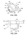
- FIG. 12Fillustrates a partial cross-section of locking member 1202 .
- Locking member 1202has a first housing 1220 and a second housing 1222 .
- First housing 1220retains therein a electric solenoid actuator 1230 that includes a coil and a plunger 1232 biased by leaf spring 1228 .
- a cover 1226is provided on housing 1220 that has an aperture that allows plunger 1232 to at least partially project there from.
- the projecting portion of plunger 1232has a pivotable lever 1224 connected thereto. Pivoting of the lever through manual actuation causes plunger 1232 to move without the need for electrical energy.
- Second housing 1222which is attached to first housing 1220 includes a channel or passage 1234 therein.
- a rod member 1236moves within passage 1234 and includes a notch 1238 therein.
- Notch 1238is configured such that when plunger 1232 is biased into passage 1234 , plunger 1232 will come into locking engagement with notch 1238 and remain there until withdrawn.
- notch 1238can be replaced by a ratcheting tooth configuration similar to that shown in FIG. 6 B.
- Rod member 1236includes at one distal end an aperture 1240 , which accepts a pin or similar fastener in forming pivotal connection 1210 .
- second housing 1222includes at one distal end first and second extensions 1246 and 1248 , each of which have aligned apertures 1244 .
- Extension 1246 and 1248accept in the space between them a pivoting bracket member that is used secure the locking member 1202 to bracket 1208 .
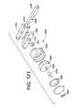
- locking member 1202Illustrated in FIG. 12I is an exploded perspective view of locking member 1202 .
- locking member 1202further includes a block 1252 that is affixed to plunger 1232 .
- Block 1252increases the effective cross-section of plunger 1238 which is responsible for locking engagement with rod member 1236 .
- Housing 1222has a cover portion 1250 that includes an aperture 1254 having substantially the same shape as block 1252 and allows block 1252 to reciprocate there within.
- locking member 1202locks the suspension system when, for example, the vehicle is not moving and motor parking brake or lock is actuated. This creates a stable platform for the user to transport in and out of the vehicle or wheelchair.
- Locking member 1202is also preferably configured to lock suspension system when the is no power or the power system has been shut off. This is achieved by always biasing plunger 1232 into locking engagement with rod member 1236 . Upon power-up, solenoid 1230 is actuated and plunger 1232 is withdrawn from the locking engagement.
- locking member 1202can be alternatively located among a plurality of positions the on suspension system 1200 .
- locking member 1202can be attached between the frame 402 and upper pivot arm 1204 A, attached between the upper and lower pivot arms 1204 A and 1204 B, or between any two components of the described four-bar pivoting assembly.
- locking member 1202can be triggered by any of the mechanisms described earlier electrical or mechanical.
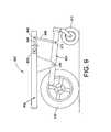
- FIG. 13Illustrated in FIG. 13 is an eighth embodiment of a locking assembly of the present invention.
- the locking assemblyhas a motor rack bracket 1314 , first ratchet 1320 , second ratchet 1322 and a spring mount 1318 . So configured, the locking assembly is shown mounted on the vehicle frame 402 , which includes a four-bar linkage pivoting front caster assembly.
- the four-bar linkage pivoting caster assemblyincludes first and second linkages 1302 and 1304 .
- a third linkageis provided by frame 402 and its extension in the form of frame bracket 1306 .
- a fourth linkageis provided by caster head tube assembly 1311 .
- First linkage 1302is pivotally connected to frame 402 at pivot 1310 and second linkage 1304 is pivotally connected to frame 402 at pivot 1308 .
- the locking assembly's motor rack bracket 1314is physically connected to first linkage 1302 through a motor/gearbox mount 1312 .
- the connectioncan also be made directly if desired.
- a gearbox 1316is also shown connected to motor/gearbox mount 1312 .
- First ratchet 1320is attached to motor rack bracket 1314 at an end portion opposite the connection to first linkage 1302 . So configured, motor rack bracket 1314 pivots when first linkage 1302 pivots.
- the locking assembly's spring mount 1318is pivotally connected to frame 402 through clevis 1325 .
- the second ratchet 1322is affixed to a side portion of the spring mount 1318 .
- Clevis 1325 and its pivotal connection 1324allow spring mount 1318 to pivot with respect to frame 402 .
- pivotal connections 1324 and 1332 and devises 1325 and 1334can be combined into a single integrated clevis and pivotal connection.
- clevis 1325can be eliminated and pivotal connection 1324 integrated into pivotal connection 1332 .
- an elastic membersuch as, for example, a spring
- spring mount 1318would include a bearing surface for bearing against one end of the spring and a spring holder.
- This configurationcan take the form of pin or bolt at least partially received within the spring, which such configuration may additionally be at least partially received within a recess in spring mount 1318 .
- the other end of the springwould bear against a bearing surface on frame 402 .
- such a configurationcan be reversed between the spring mount 1318 and frame 402 .
- a rear caster mount 1328pivotally connects rear caster 414 to frame 402 . More specifically, rear castor mount 1328 has an extension 1330 that includes a first distal end pivotally connected to clevis 1334 and a second distal end connected to a head tube portion for mounting the rear caster 414 .
- a spring 1326is situated between rear castor mount 1328 and spring mount 1318 . Spring 1326 compresses when rear caster mount 1328 pivots clockwise as shown in FIG. 13 toward frame 402 . In this manner, spring 1326 provides a degree of suspension for the rear caster mount 1328 .
- spring 1326can be replaced by a non-resilient member resulting in spring mount 1318 and rear caster mount 1328 being an integrated and rigid structure.
- spring mount 1318 and rear caster mount 1328being an integrated and rigid structure.
- such an integrated structurecan employ a single integrated pivot at pivotable connection 1332 , as opposed to pivotable connections at 1324 and 1332 .
- first and second ratchets 1320 and 1322engage each other whenever rear caster 414 is about to be lifted from its supporting surface. The condition occurs whenever the frame 402 pivots or tilts forward toward front caster 412 .
- first and second pivot arm linkages 1302 and 1304correspondingly pivot about their pivotal connection 1310 and 1308 , respectively. Any pivotal movement of linkages 1302 or 1304 translates to pivotal movement of motor rack bracket 1314 and first ratchet 1320 by virtue of their mechanical coupling.
- rear caster mount 1328pivots about its pivotal connection at 1332 causing spring mount 1318 to pivot about its pivotal connection at 1324 so that second ratchet 1322 comes into contact with first ratchet 1320 .
- pivot arm linkages 1302 and 1304are locked thereby locking frame 402 from any additional pivoting or tilting forward.
- rear caster mount 1328pivots clockwise causing spring mount 1318 to pivot clockwise and disengage second ratchet 1322 from first ratchet 1320 . This releases first and second pivot arm linkages 1302 and 1304 so that they may once again freely pivot.
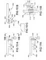
- FIGS. 14 through 16further illustrate the locking assembly and its components in perspective views.
- FIG. 15is a perspective view of the spring mount 1318 .
- Spring mount 1318further has a surface 1502 for bearing against spring 1326 and a structure 1504 holding spring 1326 in position relative spring mount 1318 .
- FIG. 16is a perspective view of rear caster mount 1328 .
- Rear caster mount 1328further has a surface 1602 for bearing against spring 1326 and a structure 1604 for holding spring 1326 in position relative to rear caster mount 1328 .
- Second ratchet 1322has a body 1702 that includes a plurality of mounting apertures 1706 that are used to fasten it to spring mount 1318 .
- Body 1702also includes a toothed surface 1704 .
- Surface 1704is slightly curved to compensate for the nature of the pivotal motion first ratchet 1320 experiences as it pivots with pivot arm linkages 1302 and 1304 .
- FIGS. 18A and 18Bare elevational and perspective views, respectively, of first ratchet 1320 .
- First ratchet 1320has a body 1804 that includes a plurality of mounting apertures 1806 , which are used to fasten first ratchet 1320 to motor rack bracket 1314 .
- Body 1804also has a toothed surface 1804 , which is slightly curved to accommodate the pivotal motion experienced by second ratchet 1322 .
- the tooth configuration of surfaces 1804 and 1704are configured such that relative motion between first and second ratchets 1320 and 1322 is more or less permitted in one direction, but motion in the opposite direction is impeded.
- pivotal connectionscan be made of any number of structures including bearing assemblies, pins, nuts and bolts, and frictionless sleeve assemblies.
- springs or shock absorberscan be added between pivoting and non-pivoting components to limit, dampen, or somewhat resist the pivotal motions of these components.
- a brake-disc locking mechanismcould be integrated into pivotal connection 406 that locks pivotal connection 406 from rotation when actuated and freely allows pivotal motion about connection 406 when not actuated. Therefore, the invention, in its broader aspects, is not limited to the specific details, the representative apparatus, and illustrative examples shown and described. Accordingly, departures can be made from such details without departing from the spirit or scope of the applicant's general inventive concept.
Landscapes
- Health & Medical Sciences (AREA)
- Life Sciences & Earth Sciences (AREA)
- Animal Behavior & Ethology (AREA)
- General Health & Medical Sciences (AREA)
- Public Health (AREA)
- Veterinary Medicine (AREA)
- Engineering & Computer Science (AREA)
- Mechanical Engineering (AREA)
- Carriages For Children, Sleds, And Other Hand-Operated Vehicles (AREA)
- Vehicle Body Suspensions (AREA)
- Automatic Cycles, And Cycles In General (AREA)
- Handcart (AREA)
Abstract
Description
If (VL+VR)>0 and (IL+IR)<−ID, then output 0V on
If (VL+VR)<0 and (IL+IR)>ID, then output 0V on
In the above equations, VL, VR, IL, and IRare the approximate terminal voltages and currents of
Claims (80)
Priority Applications (18)
| Application Number | Priority Date | Filing Date | Title |
|---|---|---|---|
| US10/643,010US6851711B2 (en) | 2002-08-16 | 2003-08-18 | Vehicle having an anti-dive/lockout mechanism |
| PCT/US2003/034124WO2004037569A2 (en) | 2002-10-25 | 2003-10-27 | Suspension with releasable locking system |
| EP03779341AEP1554140A4 (en) | 2002-10-25 | 2003-10-27 | Suspension with releasable locking system |
| PT80100258TPT2070744E (en) | 2002-10-25 | 2003-10-27 | Suspension with releasable locking system |
| EP08010025AEP2070744B1 (en) | 2002-10-25 | 2003-10-27 | Suspension with releasable locking system |
| DK08010025.8TDK2070744T3 (en) | 2002-10-25 | 2003-10-27 | Suspension with releasable locking system |
| US10/695,045US7083195B2 (en) | 2002-10-25 | 2003-10-27 | Suspension with releasable locking system |
| AU2003285024AAU2003285024A1 (en) | 2002-10-25 | 2003-10-27 | Suspension with releasable locking system |
| CA002467696ACA2467696A1 (en) | 2002-10-25 | 2003-10-27 | Suspension with releasable locking system |
| US11/077,483US7293801B2 (en) | 2003-08-18 | 2005-03-10 | Self-stabilizing suspension for wheeled vehicles |
| HK09111802.6AHK1132232B (en) | 2002-10-25 | 2006-01-19 | Suspension with releasable locking system |
| US11/472,509US8534679B2 (en) | 2002-10-25 | 2006-06-20 | Suspension for wheeled vehicles |
| US13/566,473US20120299260A1 (en) | 2002-10-25 | 2012-08-03 | Suspension for wheeled vehicles |
| US13/970,794US8833774B2 (en) | 2002-10-25 | 2013-08-20 | Suspension for wheeled vehicles |
| US14/486,766US9364377B2 (en) | 2002-10-25 | 2014-09-15 | Suspension for wheeled vehicles |
| US15/151,929US9925100B2 (en) | 2002-10-25 | 2016-05-11 | Suspension for wheeled vehicles |
| US15/935,538US10512572B2 (en) | 2002-10-25 | 2018-03-26 | Suspension for wheeled vehicles |
| US16/726,562US11213441B2 (en) | 2002-10-25 | 2019-12-24 | Suspension for wheeled vehicles |
Applications Claiming Priority (3)
| Application Number | Priority Date | Filing Date | Title |
|---|---|---|---|
| US40418002P | 2002-08-16 | 2002-08-16 | |
| US42117802P | 2002-10-25 | 2002-10-25 | |
| US10/643,010US6851711B2 (en) | 2002-08-16 | 2003-08-18 | Vehicle having an anti-dive/lockout mechanism |
Related Parent Applications (1)
| Application Number | Title | Priority Date | Filing Date |
|---|---|---|---|
| US11/077,483ContinuationUS7293801B2 (en) | 2002-10-25 | 2005-03-10 | Self-stabilizing suspension for wheeled vehicles |
Related Child Applications (1)
| Application Number | Title | Priority Date | Filing Date |
|---|---|---|---|
| US10/695,045Continuation-In-PartUS7083195B2 (en) | 2002-10-25 | 2003-10-27 | Suspension with releasable locking system |
Publications (2)
| Publication Number | Publication Date |
|---|---|
| US20040094944A1 US20040094944A1 (en) | 2004-05-20 |
| US6851711B2true US6851711B2 (en) | 2005-02-08 |
Family
ID=32179843
Family Applications (1)
| Application Number | Title | Priority Date | Filing Date |
|---|---|---|---|
| US10/643,010Expired - LifetimeUS6851711B2 (en) | 2002-08-16 | 2003-08-18 | Vehicle having an anti-dive/lockout mechanism |
Country Status (7)
| Country | Link |
|---|---|
| US (1) | US6851711B2 (en) |
| EP (2) | EP2070744B1 (en) |
| AU (1) | AU2003285024A1 (en) |
| CA (1) | CA2467696A1 (en) |
| DK (1) | DK2070744T3 (en) |
| PT (1) | PT2070744E (en) |
| WO (1) | WO2004037569A2 (en) |
Cited By (46)
| Publication number | Priority date | Publication date | Assignee | Title |
|---|---|---|---|---|
| US20040032119A1 (en)* | 2002-05-29 | 2004-02-19 | Sy Tran | Control of an anti-tip wheel in wheelchairs |
| US20050077715A1 (en)* | 2003-10-08 | 2005-04-14 | Mulhern James P. | Active anti-tip system for power wheelchairs |
| US20050077694A1 (en)* | 2003-10-08 | 2005-04-14 | Ronald Levi | Active anti-tip wheels for power wheelchair |
| US20050077714A1 (en)* | 2003-10-08 | 2005-04-14 | Mulhern James P. | Anti-tip system for wheelchairs |
| US20050151360A1 (en)* | 2003-08-18 | 2005-07-14 | Invacare Corporation | Self-stabilizing suspension for wheeled vehicles |
| US20050206149A1 (en)* | 2004-03-16 | 2005-09-22 | Mulhern James P | Bi-directional anti-tip system for powered wheelchairs |
| US20050206124A1 (en)* | 2004-03-16 | 2005-09-22 | Ronald Levi | Gear-driven anti-tip system for powered wheelchairs |
| US20050257966A1 (en)* | 2002-05-06 | 2005-11-24 | Mulhern James P | Adjustable anti-tip wheels for power wheelchair |
| US20060076748A1 (en)* | 2004-10-08 | 2006-04-13 | Sunrise Medical Hhg Inc. | Wheelchair with damping mechanism |
| US20060076747A1 (en)* | 2004-10-08 | 2006-04-13 | Sunrise Medical Hhg Inc. | Wheelchair suspension system |
| US20060175785A1 (en)* | 2004-02-25 | 2006-08-10 | Hamm Alton B | Methods of improving stability of a vehicle using a vehicle stability control system |
| US20070039766A1 (en)* | 2005-08-18 | 2007-02-22 | Jackson Mark A | Midwheel drive wheelchair with independent front and rear suspension |
| US20070045021A1 (en)* | 2005-08-29 | 2007-03-01 | Greig Mark E | Steering for a maneuverable motorized personally operated vehicle |
| US20070063502A1 (en)* | 2005-08-29 | 2007-03-22 | Greig Mark E | Steering ratio mechanism for a maneuverable motorized personally operated vehicle |
| US20070107955A1 (en)* | 2005-07-14 | 2007-05-17 | John Puskar-Pasewicz | Powered wheelchair configurations and related methods of use |
| US7222881B1 (en)* | 2004-04-27 | 2007-05-29 | Sunrise Medical Hhg Inc. | Stop for an anti-tip wheel for a wheelchair |
| US20070209848A1 (en)* | 2006-03-08 | 2007-09-13 | Chenghui Tang | Jointed mechanism of electric wheelchair |
| WO2007027502A3 (en)* | 2005-08-29 | 2007-10-25 | Sunrise Medical Hhg Inc | Maneuverable motorized personally operated vehicle |
| US20080030067A1 (en)* | 2006-06-16 | 2008-02-07 | Kwang Yang Motor Co., Ltd. | Wheel device for a frame |
| US20080042417A1 (en)* | 2006-08-17 | 2008-02-21 | Mark William Shaw | All Terrain Vehicle (ATV) safety attachment with gas tank holder |
| US20080169136A1 (en)* | 2004-04-08 | 2008-07-17 | Levo Ag Wohlen | Wheelchair With A Middle Wheel Drive, In Particular Raising Wheelchair |
| US20090091092A1 (en)* | 2001-10-10 | 2009-04-09 | Invacare Corporation | Wheelchair suspension |
| US20090145677A1 (en)* | 2006-08-16 | 2009-06-11 | Sunrise Medical Hhg Inc. | Personal mobility vehicle having a pivoting suspension with a torque activated release mechanism |
| WO2009099440A1 (en)* | 2008-02-07 | 2009-08-13 | Georgia State University Research Foundation, Inc. | Systems and methods for propelling a wheelchair |
| US20090206588A1 (en)* | 2007-07-30 | 2009-08-20 | Mark William Shaw | All terrain vehicle safety attachment with gas tank holder |
| US20100004820A1 (en)* | 2007-02-14 | 2010-01-07 | Invacare Corporation | Wheelchair with suspension |
| US20100013172A1 (en)* | 2000-10-27 | 2010-01-21 | Invacare Corporation | Obstacle traversing wheelchair |
| US20100102529A1 (en)* | 2007-01-12 | 2010-04-29 | Invacare International Sarl | Wheelchair with Suspension Arms for Wheels |
| CN101143121B (en)* | 2006-09-12 | 2010-08-18 | 光阳工业股份有限公司 | Chassis device for electric wheelchair |
| US8272461B2 (en) | 2007-02-08 | 2012-09-25 | Invacare Corporation | Wheelchair suspension |
| US8573341B2 (en) | 2001-10-19 | 2013-11-05 | Invacare Corporation | Wheelchair suspension |
| US20130306383A1 (en)* | 2010-10-05 | 2013-11-21 | James P. Mulhern | Anti-tip and suspension systems for wheelchairs |
| US8851214B2 (en) | 2010-07-15 | 2014-10-07 | Permobil Ab | Electric mid-wheel drive wheelchair |
| US9010470B2 (en) | 2009-10-09 | 2015-04-21 | Invacare Corporation | Wheelchair suspension |
| US20150196438A1 (en)* | 2013-12-16 | 2015-07-16 | Pride Mobility Products Corporation | Elevated Height Wheelchair |
| US9193240B2 (en)* | 2014-04-10 | 2015-11-24 | Chung-Chuan LIN | Damping assembly for a front-wheel independent suspension of a four-wheel mobility scooter |
| US20160045382A1 (en)* | 2013-08-28 | 2016-02-18 | Upnride Robotics Ltd | Standing wheelchair |
| US9283825B2 (en) | 2014-02-25 | 2016-03-15 | Isam Mousa | System, method, and apparatus to prevent commercial vehicle rollover |
| US9308143B2 (en) | 2012-02-15 | 2016-04-12 | Invacare Corporation | Wheelchair suspension |
| US9801766B1 (en)* | 2015-07-13 | 2017-10-31 | Ki Mobility | Multi-adjustable wheelchair and frame therefor |
| US10780929B2 (en)* | 2017-04-14 | 2020-09-22 | Exotec Solutions | Automated guided trolley for the transport and/or handling of a load |
| US11191685B2 (en) | 2016-02-27 | 2021-12-07 | Pride Mobility Products Corporation | Adjustable height wheelchair |
| US11213441B2 (en) | 2002-10-25 | 2022-01-04 | Invacare Corporation | Suspension for wheeled vehicles |
| US11839576B2 (en) | 2018-06-08 | 2023-12-12 | Sunrise Medical (Us) Llc | Dynamic rotary locking member |
| US11903887B2 (en) | 2020-02-25 | 2024-02-20 | Invacare Corporation | Wheelchair and suspension systems |
| US12409085B2 (en) | 2022-07-07 | 2025-09-09 | Permobil Ab | Powered midwheel drive wheelchair with standing capability |
Families Citing this family (12)
| Publication number | Priority date | Publication date | Assignee | Title |
|---|---|---|---|---|
| US7083195B2 (en)* | 2002-10-25 | 2006-08-01 | Invacare Corporation | Suspension with releasable locking system |
| EP1493418A1 (en)* | 2003-06-30 | 2005-01-05 | Pride Mobility Products Corporation | Suspension system for a powered wheelchair |
| US9364375B2 (en)* | 2012-01-31 | 2016-06-14 | Winco Mfg., Llc | Patient transport platform |
| JP6051777B2 (en)* | 2012-10-31 | 2016-12-27 | 株式会社ジェイテクト | Mobile vehicle and stair lift |
| AU2013347308B9 (en)* | 2012-11-13 | 2017-09-07 | Linak A/S | Castor control system |
| EP3127520B1 (en) | 2014-09-19 | 2017-12-13 | Permobil AB | Chassis arrangement for an electrically powered wheelchair and an electrically powered wheelchair comprising the same |
| US9682603B2 (en)* | 2014-10-10 | 2017-06-20 | Max Mobility, Llc | System and method for adjusting a wheelchair seat |
| US9073399B1 (en) | 2014-10-10 | 2015-07-07 | Max Mobility, Llc | System and method for adjusting a wheelchair seat |
| US10052247B2 (en) | 2015-08-24 | 2018-08-21 | Dream Roller Mobility, LLC | Wheelchair with four wheel independent suspension and modular seating |
| US10912688B2 (en) | 2015-09-25 | 2021-02-09 | The United States Government As Represented By The Department Of Veterans Affairs | Mobility enhancement wheelchair |
| US9999557B2 (en)* | 2016-07-14 | 2018-06-19 | Challenging Solutions, Inc. | Robotic mobility device |
| US10772774B2 (en)* | 2016-08-10 | 2020-09-15 | Max Mobility, Llc | Self-balancing wheelchair |
Citations (43)
| Publication number | Priority date | Publication date | Assignee | Title |
|---|---|---|---|---|
| US3174176A (en)* | 1963-01-03 | 1965-03-23 | Lockheed Aircraft Corp | Lock for relatively pivoted structures |
| US3709313A (en) | 1971-01-21 | 1973-01-09 | Walt Disney Prod | Articulated vehicle |
| US3848883A (en) | 1973-08-08 | 1974-11-19 | S Breacain | Wheelchair anti-tip apparatus |
| US3876012A (en) | 1972-01-18 | 1975-04-08 | Excel Ind | Anti-overturning implement vehicle |
| US3883153A (en)* | 1973-06-25 | 1975-05-13 | Bhupindar Singh | Apparatus for suppressing spring action between the wheel mounts and frame of a vehicle |
| US4341278A (en) | 1979-02-19 | 1982-07-27 | Wilhelm Meyer | Wheelchair |
| US4437678A (en) | 1980-08-06 | 1984-03-20 | Schultz Barry J | Vehicular suspension |
| US4500102A (en) | 1982-11-16 | 1985-02-19 | Invacare Corporation | Sports wheelchair |
| US4556229A (en) | 1982-07-09 | 1985-12-03 | Kleindienst Gmbh | Stair-climbing apparatus for wheelchair |
| USRE32242E (en) | 1980-11-13 | 1986-09-09 | Quadra Wheelchairs, Inc. | Wheelchair construction |
| US4721322A (en) | 1986-06-17 | 1988-01-26 | Hawkins Robert W | Anti-dive braking apparatus |
| US4826194A (en)* | 1987-10-26 | 1989-05-02 | Masami Sakita | Two-wheel vehicle with auxiliary support system |
| US4886294A (en) | 1988-05-12 | 1989-12-12 | Nahachewski Vladimir W | Anti-tip device for a vehicle |
| US4934626A (en) | 1988-06-07 | 1990-06-19 | Takata Corporation | Acceleration sensing device |
| US5176393A (en) | 1990-04-27 | 1993-01-05 | Medical Composite Technology | Modular wheelchair |
| US5241876A (en) | 1991-12-17 | 1993-09-07 | Houser Carter, Inc. | Device for operating a wheelchair with one arm |
| US5290055A (en) | 1992-10-07 | 1994-03-01 | Treat Jr Merritt W | Wheelchair push bar and method |
| US5294141A (en) | 1990-11-14 | 1994-03-15 | Invacare Corporation | Attended to self propelled convertible pivoting wheelchair |
| US5316328A (en) | 1993-06-14 | 1994-05-31 | Amigo Mobility International, Inc. | Bumper mounted anti-tip stabilizers for chair-mounting vehicles utilized by physically disadvantaged persons and others desiring mobility assistance, and methods of stabilizing such vehicles |
| US5351774A (en) | 1992-06-02 | 1994-10-04 | Quickie Designs Inc. | Powered wheelchair with a detachable power drive assembly |
| EP0677285A1 (en) | 1994-04-15 | 1995-10-18 | Invacare Corporation | Powered wheelchair with adjustable center of gravity and independent suspension |
| US5467838A (en)* | 1994-01-19 | 1995-11-21 | Wu; Donald P. H. | Automatically deployable vehicle stabilization system |
| US5513875A (en)* | 1991-09-09 | 1996-05-07 | Hitachi Construction Machinery Co., Ltd. | Lockable suspension system for a work vehicle having a stabilizing link |
| US5611555A (en)* | 1993-01-04 | 1997-03-18 | Vidal; Carlos C. | Articulated balancer with an oscillating axle and having locking possibilities |
| EP0908166A2 (en) | 1997-10-06 | 1999-04-14 | Invacare Corporation | Anti-tip assembly for power wheelchair |
| US5964473A (en)* | 1994-11-18 | 1999-10-12 | Degonda-Rehab S.A. | Wheelchair for transporting or assisting the displacement of at least one user, particularly for handicapped person |
| WO2000009356A1 (en) | 1998-08-14 | 2000-02-24 | Sunrise Medical Hhg Inc. | Suspension system for a wheelchair |
| WO2000008910A2 (en) | 1998-08-14 | 2000-02-24 | Sunrise Medical Hhg Inc. | Resilient suspension system for a wheelchair |
| WO2000012040A1 (en) | 1998-08-28 | 2000-03-09 | Alu Rehab A/S | Wheelchair provided with jacking apparatus and anti-tip device |
| CA2254372A1 (en)* | 1998-11-17 | 2000-05-17 | Everest & Jennings Canadian Limited | Motorized wheelchair |
| WO2000066060A1 (en) | 1999-04-29 | 2000-11-09 | Tartan Rehab Ltd. | Anti-tip devices for wheeled conveyances including wheelchairs and methods related thereto |
| US6209670B1 (en)* | 1998-11-16 | 2001-04-03 | Sunnybrook & Women's College Health Science Centre | Clutch for multi-directional transportation device |
| US6225894B1 (en) | 1998-09-24 | 2001-05-01 | Meritor Heavy Vehicle Systems, Llc | Roll-over detector for vehicles |
| US6341671B1 (en) | 2000-06-12 | 2002-01-29 | Douglas Ebersole | Wheelchair parking brake |
| US6347688B1 (en) | 2001-05-18 | 2002-02-19 | Steven R. Hall | Wheel chair rollback stop |
| US20020023787A1 (en) | 1999-06-03 | 2002-02-28 | Kamen Dean L. | Mechanical Improvements to a personal vehicle |
| US6460641B1 (en)* | 2000-06-29 | 2002-10-08 | Invacare Corporation | Mid-wheel drive wheelchair with front wheel multiple bias suspension and anti-tip assembly |
| US20020175027A1 (en) | 2001-04-10 | 2002-11-28 | Universal Medical Products, Inc. | Wheelchair brake system with anti-rollback and anti-tip capabilities |
| US6533306B2 (en) | 2001-01-18 | 2003-03-18 | Pride Mobility Products Corporation | Adjustable height anti-tip wheels for a power wheelchair |
| US6543564B1 (en) | 1994-05-27 | 2003-04-08 | Deka Products Limited Partnership | Balancing personal vehicle |
| US6543798B2 (en) | 2000-04-04 | 2003-04-08 | Pride Mobility Products Corporation | Anti-tip caster suspension for a wheelchair |
| US6588799B1 (en)* | 2001-01-09 | 2003-07-08 | Angelo Sanchez | Vehicle anti-rollover device |
| US20040032119A1 (en)* | 2002-05-29 | 2004-02-19 | Sy Tran | Control of an anti-tip wheel in wheelchairs |
Family Cites Families (10)
| Publication number | Priority date | Publication date | Assignee | Title |
|---|---|---|---|---|
| US32242A (en)* | 1861-05-07 | Printing-press | ||
| US3689103A (en)* | 1970-11-27 | 1972-09-05 | Pneumo Dynamics Corp | Variable height vehicle suspension |
| US5435404A (en) | 1992-07-31 | 1995-07-25 | Garin, Iii; Paul V. | Powered mobility chair for individual |
| US5921532A (en)* | 1994-10-07 | 1999-07-13 | Neway Anchorlok International, Inc. | Air spring with internal support member |
| US6023431A (en)* | 1996-10-03 | 2000-02-08 | Micron Technology, Inc. | Low current redundancy anti-fuse method and apparatus |
| JP4040148B2 (en)* | 1997-08-22 | 2008-01-30 | 三輪精機株式会社 | Cabbutylt device with cab lowering prevention device |
| DE19806500C2 (en)* | 1998-02-17 | 2002-03-14 | Mannesmann Sachs Ag | Lockable piston-cylinder unit |
| AUPP670498A0 (en) | 1998-10-23 | 1998-11-19 | Roller Chair Pty Ltd | Improved mid-wheel drive wheelchair |
| JP2001104391A (en) | 1999-10-08 | 2001-04-17 | Yamaha Motor Co Ltd | Wheelchair |
| US6357793B1 (en) | 1999-10-29 | 2002-03-19 | Sunrise Medical Hhg Inc. | Anti-tip wheel |
- 2003
- 2003-08-18USUS10/643,010patent/US6851711B2/ennot_activeExpired - Lifetime
- 2003-10-27DKDK08010025.8Tpatent/DK2070744T3/enactive
- 2003-10-27EPEP08010025Apatent/EP2070744B1/ennot_activeExpired - Lifetime
- 2003-10-27WOPCT/US2003/034124patent/WO2004037569A2/ennot_activeApplication Discontinuation
- 2003-10-27CACA002467696Apatent/CA2467696A1/ennot_activeAbandoned
- 2003-10-27EPEP03779341Apatent/EP1554140A4/ennot_activeWithdrawn
- 2003-10-27PTPT80100258Tpatent/PT2070744E/enunknown
- 2003-10-27AUAU2003285024Apatent/AU2003285024A1/ennot_activeAbandoned
Patent Citations (51)
| Publication number | Priority date | Publication date | Assignee | Title |
|---|---|---|---|---|
| US3174176A (en)* | 1963-01-03 | 1965-03-23 | Lockheed Aircraft Corp | Lock for relatively pivoted structures |
| US3709313A (en) | 1971-01-21 | 1973-01-09 | Walt Disney Prod | Articulated vehicle |
| US3876012A (en) | 1972-01-18 | 1975-04-08 | Excel Ind | Anti-overturning implement vehicle |
| US3883153A (en)* | 1973-06-25 | 1975-05-13 | Bhupindar Singh | Apparatus for suppressing spring action between the wheel mounts and frame of a vehicle |
| US3848883A (en) | 1973-08-08 | 1974-11-19 | S Breacain | Wheelchair anti-tip apparatus |
| US4341278A (en) | 1979-02-19 | 1982-07-27 | Wilhelm Meyer | Wheelchair |
| US4437678A (en) | 1980-08-06 | 1984-03-20 | Schultz Barry J | Vehicular suspension |
| USRE32242E (en) | 1980-11-13 | 1986-09-09 | Quadra Wheelchairs, Inc. | Wheelchair construction |
| US4556229A (en) | 1982-07-09 | 1985-12-03 | Kleindienst Gmbh | Stair-climbing apparatus for wheelchair |
| US4500102A (en) | 1982-11-16 | 1985-02-19 | Invacare Corporation | Sports wheelchair |
| US4721322A (en) | 1986-06-17 | 1988-01-26 | Hawkins Robert W | Anti-dive braking apparatus |
| US4826194A (en)* | 1987-10-26 | 1989-05-02 | Masami Sakita | Two-wheel vehicle with auxiliary support system |
| US4886294A (en) | 1988-05-12 | 1989-12-12 | Nahachewski Vladimir W | Anti-tip device for a vehicle |
| US4934626A (en) | 1988-06-07 | 1990-06-19 | Takata Corporation | Acceleration sensing device |
| US5176393A (en) | 1990-04-27 | 1993-01-05 | Medical Composite Technology | Modular wheelchair |
| US5294141A (en) | 1990-11-14 | 1994-03-15 | Invacare Corporation | Attended to self propelled convertible pivoting wheelchair |
| US5513875A (en)* | 1991-09-09 | 1996-05-07 | Hitachi Construction Machinery Co., Ltd. | Lockable suspension system for a work vehicle having a stabilizing link |
| US5241876A (en) | 1991-12-17 | 1993-09-07 | Houser Carter, Inc. | Device for operating a wheelchair with one arm |
| US5351774A (en) | 1992-06-02 | 1994-10-04 | Quickie Designs Inc. | Powered wheelchair with a detachable power drive assembly |
| US5531284A (en) | 1992-06-02 | 1996-07-02 | Quickie Designs Inc. | Powered wheelchair with a detachable power drive assembly |
| US5290055A (en) | 1992-10-07 | 1994-03-01 | Treat Jr Merritt W | Wheelchair push bar and method |
| US5611555A (en)* | 1993-01-04 | 1997-03-18 | Vidal; Carlos C. | Articulated balancer with an oscillating axle and having locking possibilities |
| US5316328A (en) | 1993-06-14 | 1994-05-31 | Amigo Mobility International, Inc. | Bumper mounted anti-tip stabilizers for chair-mounting vehicles utilized by physically disadvantaged persons and others desiring mobility assistance, and methods of stabilizing such vehicles |
| US5467838A (en)* | 1994-01-19 | 1995-11-21 | Wu; Donald P. H. | Automatically deployable vehicle stabilization system |
| EP0677285A1 (en) | 1994-04-15 | 1995-10-18 | Invacare Corporation | Powered wheelchair with adjustable center of gravity and independent suspension |
| US5575348A (en) | 1994-04-15 | 1996-11-19 | Invacare Corporation | Powered wheelchair with adjustable center of gravity and independent suspension |
| US5853059A (en) | 1994-04-15 | 1998-12-29 | Invacare Corporation | Powered wheelchair with adjustable center of gravity and independent suspension |
| US6543564B1 (en) | 1994-05-27 | 2003-04-08 | Deka Products Limited Partnership | Balancing personal vehicle |
| US5964473A (en)* | 1994-11-18 | 1999-10-12 | Degonda-Rehab S.A. | Wheelchair for transporting or assisting the displacement of at least one user, particularly for handicapped person |
| US6041876A (en) | 1997-10-06 | 2000-03-28 | Invacare Corporation | Anti-tip assembly for power wheelchair |
| EP0908166A2 (en) | 1997-10-06 | 1999-04-14 | Invacare Corporation | Anti-tip assembly for power wheelchair |
| US6131679A (en)* | 1997-10-06 | 2000-10-17 | Invacare Corporation | Anti-tip assembly for power wheelchair |
| WO2000008910A2 (en) | 1998-08-14 | 2000-02-24 | Sunrise Medical Hhg Inc. | Resilient suspension system for a wheelchair |
| US6070898A (en) | 1998-08-14 | 2000-06-06 | Sunrise Medical, Inc. | Suspension system for a wheelchair |
| WO2000009356A1 (en) | 1998-08-14 | 2000-02-24 | Sunrise Medical Hhg Inc. | Suspension system for a wheelchair |
| US6234507B1 (en) | 1998-08-14 | 2001-05-22 | Sunrise Medical Hhg Inc. | Suspension system for a wheelchair |
| WO2000012040A1 (en) | 1998-08-28 | 2000-03-09 | Alu Rehab A/S | Wheelchair provided with jacking apparatus and anti-tip device |
| US6225894B1 (en) | 1998-09-24 | 2001-05-01 | Meritor Heavy Vehicle Systems, Llc | Roll-over detector for vehicles |
| US6209670B1 (en)* | 1998-11-16 | 2001-04-03 | Sunnybrook & Women's College Health Science Centre | Clutch for multi-directional transportation device |
| CA2254372A1 (en)* | 1998-11-17 | 2000-05-17 | Everest & Jennings Canadian Limited | Motorized wheelchair |
| WO2000066060A1 (en) | 1999-04-29 | 2000-11-09 | Tartan Rehab Ltd. | Anti-tip devices for wheeled conveyances including wheelchairs and methods related thereto |
| US20020023787A1 (en) | 1999-06-03 | 2002-02-28 | Kamen Dean L. | Mechanical Improvements to a personal vehicle |
| US6405816B1 (en) | 1999-06-03 | 2002-06-18 | Deka Products Limited Partnership | Mechanical improvements to a personal vehicle |
| US6543798B2 (en) | 2000-04-04 | 2003-04-08 | Pride Mobility Products Corporation | Anti-tip caster suspension for a wheelchair |
| US6341671B1 (en) | 2000-06-12 | 2002-01-29 | Douglas Ebersole | Wheelchair parking brake |
| US6460641B1 (en)* | 2000-06-29 | 2002-10-08 | Invacare Corporation | Mid-wheel drive wheelchair with front wheel multiple bias suspension and anti-tip assembly |
| US6588799B1 (en)* | 2001-01-09 | 2003-07-08 | Angelo Sanchez | Vehicle anti-rollover device |
| US6533306B2 (en) | 2001-01-18 | 2003-03-18 | Pride Mobility Products Corporation | Adjustable height anti-tip wheels for a power wheelchair |
| US20020175027A1 (en) | 2001-04-10 | 2002-11-28 | Universal Medical Products, Inc. | Wheelchair brake system with anti-rollback and anti-tip capabilities |
| US6347688B1 (en) | 2001-05-18 | 2002-02-19 | Steven R. Hall | Wheel chair rollback stop |
| US20040032119A1 (en)* | 2002-05-29 | 2004-02-19 | Sy Tran | Control of an anti-tip wheel in wheelchairs |
Cited By (126)
| Publication number | Priority date | Publication date | Assignee | Title |
|---|---|---|---|---|
| US9149398B2 (en) | 2000-10-27 | 2015-10-06 | Invacare Corporation | Obstacle traversing wheelchair |
| US9987177B2 (en) | 2000-10-27 | 2018-06-05 | Invacare Corporation | Obstacle traversing wheelchair |
| US8172016B2 (en) | 2000-10-27 | 2012-05-08 | Invacare Corporation | Obstacle traversing wheelchair |
| US20100013172A1 (en)* | 2000-10-27 | 2010-01-21 | Invacare Corporation | Obstacle traversing wheelchair |
| US20090091092A1 (en)* | 2001-10-10 | 2009-04-09 | Invacare Corporation | Wheelchair suspension |
| US20160256337A1 (en)* | 2001-10-10 | 2016-09-08 | Invacare Corporation | Wheelchair suspension |
| US8172015B2 (en) | 2001-10-10 | 2012-05-08 | Invacare Corporation | Wheelchair suspension |
| US9370455B2 (en) | 2001-10-10 | 2016-06-21 | Invacare Corporation | Wheelchair suspension |
| US8573341B2 (en) | 2001-10-19 | 2013-11-05 | Invacare Corporation | Wheelchair suspension |
| US20050257966A1 (en)* | 2002-05-06 | 2005-11-24 | Mulhern James P | Adjustable anti-tip wheels for power wheelchair |
| US7344155B2 (en) | 2002-05-06 | 2008-03-18 | Pride Mobility Products Corporation | Adjustable anti-tip wheels for power wheelchair |
| US20040032119A1 (en)* | 2002-05-29 | 2004-02-19 | Sy Tran | Control of an anti-tip wheel in wheelchairs |
| US20060244249A1 (en)* | 2002-10-25 | 2006-11-02 | Gerold Goertzen | Suspension for wheeled vehicles |
| US9925100B2 (en) | 2002-10-25 | 2018-03-27 | Invacare Corporation | Suspension for wheeled vehicles |
| US8534679B2 (en) | 2002-10-25 | 2013-09-17 | Invacare Corporation | Suspension for wheeled vehicles |
| US11213441B2 (en) | 2002-10-25 | 2022-01-04 | Invacare Corporation | Suspension for wheeled vehicles |
| US9364377B2 (en) | 2002-10-25 | 2016-06-14 | Invacare Corporation | Suspension for wheeled vehicles |
| US10512572B2 (en) | 2002-10-25 | 2019-12-24 | Invacare Corporation | Suspension for wheeled vehicles |
| US20050151360A1 (en)* | 2003-08-18 | 2005-07-14 | Invacare Corporation | Self-stabilizing suspension for wheeled vehicles |
| US7293801B2 (en) | 2003-08-18 | 2007-11-13 | Invacare Corporation | Self-stabilizing suspension for wheeled vehicles |
| US9301894B2 (en) | 2003-10-08 | 2016-04-05 | Pride Mobility Products Corporation | Anti-tip system for a power wheelchair |
| US7413038B2 (en) | 2003-10-08 | 2008-08-19 | Pride Mobility Products Corporation | Anti-tip system for a power wheelchair |
| US8181992B2 (en) | 2003-10-08 | 2012-05-22 | Pride Mobility Products Corporation | Anti-tip system for a power wheelchair |
| US7316282B2 (en) | 2003-10-08 | 2008-01-08 | Pride Mobility Products Corporation | Anti-tip system for wheelchairs |
| US7232008B2 (en) | 2003-10-08 | 2007-06-19 | Pride Mobility Products Corporation | Active anti-tip wheels for power wheelchair |
| US20050077715A1 (en)* | 2003-10-08 | 2005-04-14 | Mulhern James P. | Active anti-tip system for power wheelchairs |
| US20050077694A1 (en)* | 2003-10-08 | 2005-04-14 | Ronald Levi | Active anti-tip wheels for power wheelchair |
| US7389835B2 (en) | 2003-10-08 | 2008-06-24 | Pride Mobility Products Corporation | Active anti-tip system for power wheelchairs |
| US20050077714A1 (en)* | 2003-10-08 | 2005-04-14 | Mulhern James P. | Anti-tip system for wheelchairs |
| US20060022445A1 (en)* | 2003-10-08 | 2006-02-02 | Mulhern James P | Anti-tip system for a power wheelchair |
| US20110108348A1 (en)* | 2003-10-08 | 2011-05-12 | Pride Mobility Products Corporation | Anti-Tip System for a Power Wheelchair |
| US7931300B2 (en) | 2003-10-08 | 2011-04-26 | Pride Mobility Products Corporation | Anti-tip system for a power wheelchair |
| US8408598B2 (en) | 2003-10-08 | 2013-04-02 | Pride Mobility Products Corporation | Anti-tip system for a power wheelchair |
| US20100219623A1 (en)* | 2003-10-08 | 2010-09-02 | Pride Mobility Products Corporation | Anti-Tip System for a Power Wheelchair |
| US9526664B2 (en) | 2003-10-08 | 2016-12-27 | Pride Mobility Products Corporation | Anti-tip system for a power wheelchair |
| US7726689B2 (en) | 2003-10-08 | 2010-06-01 | Pride Mobility Products Corporation | Anti-tip system for a power wheelchair |
| US20060175785A1 (en)* | 2004-02-25 | 2006-08-10 | Hamm Alton B | Methods of improving stability of a vehicle using a vehicle stability control system |
| US20050206124A1 (en)* | 2004-03-16 | 2005-09-22 | Ronald Levi | Gear-driven anti-tip system for powered wheelchairs |
| US7264272B2 (en) | 2004-03-16 | 2007-09-04 | Pride Mobility Products Corporation | Bi-directional anti-tip system for powered wheelchairs |
| US20050206149A1 (en)* | 2004-03-16 | 2005-09-22 | Mulhern James P | Bi-directional anti-tip system for powered wheelchairs |
| US20080169136A1 (en)* | 2004-04-08 | 2008-07-17 | Levo Ag Wohlen | Wheelchair With A Middle Wheel Drive, In Particular Raising Wheelchair |
| US7222881B1 (en)* | 2004-04-27 | 2007-05-29 | Sunrise Medical Hhg Inc. | Stop for an anti-tip wheel for a wheelchair |
| US20060076747A1 (en)* | 2004-10-08 | 2006-04-13 | Sunrise Medical Hhg Inc. | Wheelchair suspension system |
| US20060076748A1 (en)* | 2004-10-08 | 2006-04-13 | Sunrise Medical Hhg Inc. | Wheelchair with damping mechanism |
| US9333130B2 (en) | 2005-07-14 | 2016-05-10 | Pride Mobility Products Corporation | Powered wheelchair configurations and related methods of use |
| US8408343B2 (en) | 2005-07-14 | 2013-04-02 | Pride Mobility Products Corporation | Powered wheelchair configurations and related methods of use |
| US8292010B2 (en) | 2005-07-14 | 2012-10-23 | Pride Mobility Products Corporation | Powered wheelchair configurations and related methods of use |
| US20100258363A1 (en)* | 2005-07-14 | 2010-10-14 | Pride Mobility Products Corporation | Powered wheelchair configurations and related methods of use |
| US9872804B2 (en) | 2005-07-14 | 2018-01-23 | Pride Mobility Products Corporation | Powered wheelchair configurations and related methods of use |
| US20070107955A1 (en)* | 2005-07-14 | 2007-05-17 | John Puskar-Pasewicz | Powered wheelchair configurations and related methods of use |
| US7766106B2 (en) | 2005-07-14 | 2010-08-03 | Pride Mobility Products Corporation | Powered wheelchair configurations and related methods of use |
| US20070039766A1 (en)* | 2005-08-18 | 2007-02-22 | Jackson Mark A | Midwheel drive wheelchair with independent front and rear suspension |
| US8469383B2 (en)* | 2005-08-18 | 2013-06-25 | Sunrise Medical (Us) Llc | Midwheel drive wheelchair with independent front and rear suspension |
| US7896394B2 (en) | 2005-08-18 | 2011-03-01 | Sunrise Medical Hhg, Inc. | Midwheel drive wheelchair with independent front and rear suspension |
| US20120273283A1 (en)* | 2005-08-18 | 2012-11-01 | Sunrise Medical Hhg, Inc. | Midwheel drive wheelchair with independent front and rear suspension |
| WO2007027502A3 (en)* | 2005-08-29 | 2007-10-25 | Sunrise Medical Hhg Inc | Maneuverable motorized personally operated vehicle |
| US20070063502A1 (en)* | 2005-08-29 | 2007-03-22 | Greig Mark E | Steering ratio mechanism for a maneuverable motorized personally operated vehicle |
| US20070045021A1 (en)* | 2005-08-29 | 2007-03-01 | Greig Mark E | Steering for a maneuverable motorized personally operated vehicle |
| US7516984B2 (en)* | 2006-03-08 | 2009-04-14 | Chenghui Tang | Jointed mechanism of electric wheelchair |
| US20070209848A1 (en)* | 2006-03-08 | 2007-09-13 | Chenghui Tang | Jointed mechanism of electric wheelchair |
| US20080030067A1 (en)* | 2006-06-16 | 2008-02-07 | Kwang Yang Motor Co., Ltd. | Wheel device for a frame |
| US8113531B2 (en)* | 2006-08-16 | 2012-02-14 | Sunrise Medical Hhg, Inc. | Personal mobility vehicle having a pivoting suspension with a torque activated release mechanism |
| US20090145677A1 (en)* | 2006-08-16 | 2009-06-11 | Sunrise Medical Hhg Inc. | Personal mobility vehicle having a pivoting suspension with a torque activated release mechanism |
| US20080042417A1 (en)* | 2006-08-17 | 2008-02-21 | Mark William Shaw | All Terrain Vehicle (ATV) safety attachment with gas tank holder |
| US7665766B2 (en)* | 2006-08-17 | 2010-02-23 | Mark William Shaw | All terrain vehicle (ATV) safety attachment with gas tank holder |
| CN101143121B (en)* | 2006-09-12 | 2010-08-18 | 光阳工业股份有限公司 | Chassis device for electric wheelchair |
| US8297388B2 (en) | 2007-01-12 | 2012-10-30 | Invacare International Sarl | Wheelchair with suspension arms |
| US20100102529A1 (en)* | 2007-01-12 | 2010-04-29 | Invacare International Sarl | Wheelchair with Suspension Arms for Wheels |
| US8794359B2 (en) | 2007-02-08 | 2014-08-05 | Invacare Corporation | Wheelchair suspension |
| US10265229B2 (en) | 2007-02-08 | 2019-04-23 | Invacare Corporation | Wheelchair suspension |
| US9603762B2 (en) | 2007-02-08 | 2017-03-28 | Invacare Corporation | Wheelchair suspension |
| US11819464B2 (en) | 2007-02-08 | 2023-11-21 | Invacare Corporation | Wheelchair suspension |
| US11464687B2 (en) | 2007-02-08 | 2022-10-11 | Invacare Coporation | Wheelchair suspension |
| US8272461B2 (en) | 2007-02-08 | 2012-09-25 | Invacare Corporation | Wheelchair suspension |
| US10912690B2 (en) | 2007-02-08 | 2021-02-09 | Invacare Corporation | Wheelchair suspension |
| US10532626B2 (en) | 2007-02-14 | 2020-01-14 | Invacare Corporation | Stability control system |
| US8910975B2 (en) | 2007-02-14 | 2014-12-16 | Invacare Corporation | Wheelchair with suspension |
| US9827823B2 (en) | 2007-02-14 | 2017-11-28 | Invacare Corporation | Stability control system |
| US9346335B2 (en) | 2007-02-14 | 2016-05-24 | Invacare Corporation | Stability control system |
| EP2340800A2 (en) | 2007-02-14 | 2011-07-06 | Invacare Corporation | Stability control system |
| EP2332506A1 (en) | 2007-02-14 | 2011-06-15 | Invacare Corporation | Stability control system |
| US11535078B2 (en) | 2007-02-14 | 2022-12-27 | Invacare Corporation | Stability control system |
| US20100004820A1 (en)* | 2007-02-14 | 2010-01-07 | Invacare Corporation | Wheelchair with suspension |
| US11850906B2 (en) | 2007-02-14 | 2023-12-26 | Invacare Corporation | Stability control system |
| US11097589B2 (en) | 2007-02-14 | 2021-08-24 | Invacare Corporation | Stability control system |
| US20090206588A1 (en)* | 2007-07-30 | 2009-08-20 | Mark William Shaw | All terrain vehicle safety attachment with gas tank holder |
| US7789424B2 (en)* | 2007-07-30 | 2010-09-07 | Mark William Shaw | All terrain vehicle safety attachment with gas tank holder |
| WO2009099440A1 (en)* | 2008-02-07 | 2009-08-13 | Georgia State University Research Foundation, Inc. | Systems and methods for propelling a wheelchair |
| US9010470B2 (en) | 2009-10-09 | 2015-04-21 | Invacare Corporation | Wheelchair suspension |
| US9913768B2 (en) | 2009-10-09 | 2018-03-13 | Invacare Corporation | Wheelchair suspension |
| US11857470B2 (en) | 2009-10-09 | 2024-01-02 | Invacare Corporation | Wheelchair suspension |
| US11096845B2 (en) | 2009-10-09 | 2021-08-24 | Invacare Corporation | Wheelchair suspension |
| US9320661B2 (en) | 2010-07-15 | 2016-04-26 | Permobil Ab | Electric mid-wheel drive wheelchair |
| US8851214B2 (en) | 2010-07-15 | 2014-10-07 | Permobil Ab | Electric mid-wheel drive wheelchair |
| US9474664B2 (en)* | 2010-10-05 | 2016-10-25 | Pride Mobility Products Corporation | Anti-tip and suspension systems for wheelchairs |
| US20130306383A1 (en)* | 2010-10-05 | 2013-11-21 | James P. Mulhern | Anti-tip and suspension systems for wheelchairs |
| US11234875B2 (en) | 2012-02-15 | 2022-02-01 | Invacare Corporation | Wheelchair suspension |
| US9308143B2 (en) | 2012-02-15 | 2016-04-12 | Invacare Corporation | Wheelchair suspension |
| US9700470B2 (en) | 2012-02-15 | 2017-07-11 | Invacare Corporation | Wheelchair suspension |
| US10434019B2 (en) | 2012-02-15 | 2019-10-08 | Invacare Corporation | Wheelchair suspension |
| US10172752B2 (en)* | 2013-08-28 | 2019-01-08 | Upnride Robotics Ltd | Standing wheelchair |
| US20160045382A1 (en)* | 2013-08-28 | 2016-02-18 | Upnride Robotics Ltd | Standing wheelchair |
| US10828212B2 (en)* | 2013-12-16 | 2020-11-10 | Pride Mobility Products Corporation | Elevated height wheelchair |
| US20150196441A1 (en)* | 2013-12-16 | 2015-07-16 | Pride Mobility Products Corporation | Elevated Height Wheelchair |
| US10561548B1 (en) | 2013-12-16 | 2020-02-18 | Pride Mobility Products Corporation | Elevated height wheelchair |
| US10588797B2 (en)* | 2013-12-16 | 2020-03-17 | Pride Mobility Products Corporation | Elevated height wheelchair |
| US20200179194A1 (en)* | 2013-12-16 | 2020-06-11 | Pride Mobility Products Corporation | Elevated Height Wheelchair |
| US10687997B2 (en)* | 2013-12-16 | 2020-06-23 | Pride Mobility Products Corporation | Elevated height wheelchair |
| US9808383B2 (en)* | 2013-12-16 | 2017-11-07 | Pride Mobility Products Corporation | Elevated height wheelchair |
| US20180055702A1 (en)* | 2013-12-16 | 2018-03-01 | Pride Mobility Products Corporation | Elevated Height Wheelchair |
| US9351889B2 (en)* | 2013-12-16 | 2016-05-31 | Pride Mobility Products Corporation | Elevated height wheelchair |
| US20150196438A1 (en)* | 2013-12-16 | 2015-07-16 | Pride Mobility Products Corporation | Elevated Height Wheelchair |
| US11571345B2 (en) | 2013-12-16 | 2023-02-07 | Pride Mobility Products Corporation | Elevated height wheelchair |
| US11141330B2 (en) | 2013-12-16 | 2021-10-12 | Pride Mobility Products Corporation | Elevated height wheelchair |
| US9566200B2 (en)* | 2013-12-16 | 2017-02-14 | Pride Mobility Products Corporation | Elevated height wheelchair |
| US20190029899A1 (en)* | 2013-12-16 | 2019-01-31 | Pride Mobility Products Corporation | Elevated Height Wheelchair |
| US10130532B2 (en)* | 2013-12-16 | 2018-11-20 | Pride Mobility Products Corporation | Elevated height wheelchair |
| US9283825B2 (en) | 2014-02-25 | 2016-03-15 | Isam Mousa | System, method, and apparatus to prevent commercial vehicle rollover |
| US9193240B2 (en)* | 2014-04-10 | 2015-11-24 | Chung-Chuan LIN | Damping assembly for a front-wheel independent suspension of a four-wheel mobility scooter |
| US10238556B1 (en) | 2015-07-13 | 2019-03-26 | Ki Mobility, LLC | Multi-adjustable wheelchair and frame therefor |
| US9801766B1 (en)* | 2015-07-13 | 2017-10-31 | Ki Mobility | Multi-adjustable wheelchair and frame therefor |
| US11191685B2 (en) | 2016-02-27 | 2021-12-07 | Pride Mobility Products Corporation | Adjustable height wheelchair |
| US10780929B2 (en)* | 2017-04-14 | 2020-09-22 | Exotec Solutions | Automated guided trolley for the transport and/or handling of a load |
| US11839576B2 (en) | 2018-06-08 | 2023-12-12 | Sunrise Medical (Us) Llc | Dynamic rotary locking member |
| US11903887B2 (en) | 2020-02-25 | 2024-02-20 | Invacare Corporation | Wheelchair and suspension systems |
| US12409085B2 (en) | 2022-07-07 | 2025-09-09 | Permobil Ab | Powered midwheel drive wheelchair with standing capability |
Also Published As
| Publication number | Publication date |
|---|---|
| AU2003285024A1 (en) | 2004-05-13 |
| PT2070744E (en) | 2013-08-28 |
| EP2070744A1 (en) | 2009-06-17 |
| HK1132232A1 (en) | 2010-02-19 |
| WO2004037569A3 (en) | 2005-02-10 |
| CA2467696A1 (en) | 2004-05-06 |
| DK2070744T3 (en) | 2014-06-02 |
| EP2070744B1 (en) | 2013-04-03 |
| US20040094944A1 (en) | 2004-05-20 |
| EP1554140A2 (en) | 2005-07-20 |
| WO2004037569A2 (en) | 2004-05-06 |
| EP1554140A4 (en) | 2009-06-03 |
Similar Documents
| Publication | Publication Date | Title |
|---|---|---|
| US6851711B2 (en) | Vehicle having an anti-dive/lockout mechanism | |
| US7083195B2 (en) | Suspension with releasable locking system | |
| US10512572B2 (en) | Suspension for wheeled vehicles | |
| US11213441B2 (en) | Suspension for wheeled vehicles | |
| CA2495751C (en) | Vehicle having an anti-dive/lockout mechanism | |
| CA2676724C (en) | Stability control system | |
| CA2838376C (en) | Vehicle having an anti-dive/lockout mechanism | |
| CA2793015C (en) | Vehicle having an anti-dive/lockout mechanism | |
| HK1132232B (en) | Suspension with releasable locking system |
Legal Events
| Date | Code | Title | Description |
|---|---|---|---|
| AS | Assignment | Owner name:INVACARE CORPORATION, OHIO Free format text:ASSIGNMENT OF ASSIGNORS INTEREST;ASSIGNORS:GOERTZEN, GERALD;JULL, WILLIAM A., JR.;REEL/FRAME:014848/0564 Effective date:20031201 | |
| STCF | Information on status: patent grant | Free format text:PATENTED CASE | |
| AS | Assignment | Owner name:NATIONAL CITY BANK, AS MULTICURRENCY COLLATERAL AG Free format text:NOTICE OF GRANT OF SECURITY INTEREST;ASSIGNOR:INVACARE CORPORATION;REEL/FRAME:019009/0134 Effective date:20070212 | |
| FPAY | Fee payment | Year of fee payment:4 | |
| AS | Assignment | Owner name:PNC BANK, NATIONAL ASSOCIATION, PENNSYLVANIA Free format text:SECURITY AGREEMENT;ASSIGNORS:INVACARE CORPORATION;ADAPTIVE SWITCH LABORATORIES, INC.;THE AFTERMARKET GROUP, INC.;AND OTHERS;REEL/FRAME:025473/0311 Effective date:20101028 | |
| FPAY | Fee payment | Year of fee payment:8 | |
| FEPP | Fee payment procedure | Free format text:PAYOR NUMBER ASSIGNED (ORIGINAL EVENT CODE: ASPN); ENTITY STATUS OF PATENT OWNER: LARGE ENTITY | |
| FEPP | Fee payment procedure | Free format text:PAYER NUMBER DE-ASSIGNED (ORIGINAL EVENT CODE: RMPN); ENTITY STATUS OF PATENT OWNER: LARGE ENTITY Free format text:PAYOR NUMBER ASSIGNED (ORIGINAL EVENT CODE: ASPN); ENTITY STATUS OF PATENT OWNER: LARGE ENTITY | |
| FPAY | Fee payment | Year of fee payment:12 | |
| AS | Assignment | Owner name:GLAS TRUST CORPORATION LIMITED, AS COLLATERAL AGENT, UNITED KINGDOM Free format text:PATENT SECURITY AGREEMENT (TRANCHE II NOTES);ASSIGNORS:INVACARE CORPORATION;FREEDOM DESIGNS, INC.;REEL/FRAME:061131/0852 Effective date:20220726 Owner name:GLAS TRUST CORPORATION LIMITED, AS COLLATERAL AGENT, UNITED KINGDOM Free format text:PATENT SECURITY AGREEMENT (TRANCHE I NOTES);ASSIGNORS:INVACARE CORPORATION;FREEDOM DESIGNS, INC.;REEL/FRAME:061131/0833 Effective date:20220726 Owner name:GLAS TRUST CORPORATION LIMITED, AS COLLATERAL AGENT, UNITED KINGDOM Free format text:PATENT SECURITY AGREEMENT (TERM LOAN);ASSIGNORS:INVACARE CORPORATION;FREEDOM DESIGNS, INC.;REEL/FRAME:061131/0814 Effective date:20220726 | |
| AS | Assignment | Owner name:GLAS TRUST CORPORATION LIMITED, AS COLLATERAL AGENT, UNITED KINGDOM Free format text:PATENT SECURITY AGREEMENT;ASSIGNORS:INVACARE CORPORATION;MOTION CONCEPTS L.P.;FREEDOM DESIGNS, INC.;REEL/FRAME:063090/0603 Effective date:20230202 Owner name:PNC BANK, NATIONAL ASSOCIATION, PENNSYLVANIA Free format text:SECURITY INTEREST;ASSIGNORS:INVACARE CORPORATION;ADAPTIVE SWITCH LABORATORIES, INC.;FREEDOM DESIGNS, INC.;AND OTHERS;REEL/FRAME:062739/0687 Effective date:20230202 | |
| AS | Assignment | Owner name:WHITE OAK COMMERCIAL FINANCE, LLC, AS COLLATERAL AGENT, CALIFORNIA Free format text:SECURITY INTEREST;ASSIGNORS:INVACARE CORPORATION;FREEDOM DESIGNS, INC.;MOTION CONCEPTS L.P.;REEL/FRAME:063553/0217 Effective date:20230505 | |
| AS | Assignment | Owner name:FREEDOM DESIGNS, INC., CALIFORNIA Free format text:INTELLECTUAL PROPERTY RELEASE (TRANCHE II NOTES);ASSIGNOR:GLAS TRUST CORPORATION LIMITED, AS COLLATERAL AGENT;REEL/FRAME:063601/0183 Effective date:20230505 Owner name:INVACARE CORPORATION, OHIO Free format text:INTELLECTUAL PROPERTY RELEASE (TRANCHE II NOTES);ASSIGNOR:GLAS TRUST CORPORATION LIMITED, AS COLLATERAL AGENT;REEL/FRAME:063601/0183 Effective date:20230505 Owner name:MOTION CONCEPTS L.P., CANADA Free format text:INTELLECTUAL PROPERTY RELEASE (DIP PAYOFF);ASSIGNOR:GLAS TRUST CORPORATION LIMITED, AS COLLATERAL AGENT;REEL/FRAME:063594/0272 Effective date:20230505 Owner name:FREEDOM DESIGNS, INC., CALIFORNIA Free format text:INTELLECTUAL PROPERTY RELEASE (DIP PAYOFF);ASSIGNOR:GLAS TRUST CORPORATION LIMITED, AS COLLATERAL AGENT;REEL/FRAME:063594/0272 Effective date:20230505 Owner name:INVACARE CORPORATION, OHIO Free format text:INTELLECTUAL PROPERTY RELEASE (DIP PAYOFF);ASSIGNOR:GLAS TRUST CORPORATION LIMITED, AS COLLATERAL AGENT;REEL/FRAME:063594/0272 Effective date:20230505 Owner name:FREEDOM DESIGNS, INC., CALIFORNIA Free format text:INTELLECTUAL PROPERTY RELEASE (TRANCHE I NOTES);ASSIGNOR:GLAS TRUST CORPORATION LIMITED, AS COLLATERAL AGENT;REEL/FRAME:063594/0906 Effective date:20230505 Owner name:INVACARE CORPORATION, OHIO Free format text:INTELLECTUAL PROPERTY RELEASE (TRANCHE I NOTES);ASSIGNOR:GLAS TRUST CORPORATION LIMITED, AS COLLATERAL AGENT;REEL/FRAME:063594/0906 Effective date:20230505 | |
| AS | Assignment | Owner name:GLAS TRUST COMPANY LLC, AS SUCCESSOR COLLATERAL AGENT, NEW JERSEY Free format text:ASSIGNMENT OF SECURITY INTEREST IN INTELLECTUAL PROPERTY RIGHTS;ASSIGNOR:GLAS TRUST CORPORATION LIMITED, AS EXISTING COLLATERAL AGENT;REEL/FRAME:063625/0607 Effective date:20230505 | |
| AS | Assignment | Owner name:GLAS TRUST COMPANY LLC, AS COLLATERAL AGENT, NEW JERSEY Free format text:PATENT SECURITY AGREEMENT (TRANCHE I NOTES);ASSIGNORS:INVACARE CORPORATION;MOTION CONCEPTS L.P;FREEDOM DESIGNS, INC.;REEL/FRAME:064005/0231 Effective date:20230505 | |
| AS | Assignment | Owner name:INVACARE CORPORATION, OHIO Free format text:RELEASE BY SECURED PARTY;ASSIGNOR:PNC BANK, NATIONAL ASSOCIATION;REEL/FRAME:063638/0261 Effective date:20230505 Owner name:GLAS TRUST COMPANY LLC, AS COLLATERAL AGENT, NEW JERSEY Free format text:PATENT SECURITY AGREEMENT (TRANCHE II NOTES);ASSIGNORS:INVACARE CORPORATION;MOTION CONCEPTS L.P;FREEDOM DESIGNS, INC.;REEL/FRAME:063637/0705 Effective date:20230505 | |
| AS | Assignment | Owner name:INVACARE HCS, LLC, OHIO Free format text:RELEASE BY SECURED PARTY;ASSIGNOR:PNC BANK, NATIONAL ASSOCIATION;REEL/FRAME:063668/0679 Effective date:20230505 Owner name:INVACARE FLORIDA HOLDINGS, LLC, OHIO Free format text:RELEASE BY SECURED PARTY;ASSIGNOR:PNC BANK, NATIONAL ASSOCIATION;REEL/FRAME:063668/0679 Effective date:20230505 Owner name:GARDEN CITY MEDICAL INC., OHIO Free format text:RELEASE BY SECURED PARTY;ASSIGNOR:PNC BANK, NATIONAL ASSOCIATION;REEL/FRAME:063668/0679 Effective date:20230505 Owner name:FREEDOM DESIGNS, INC., OHIO Free format text:RELEASE BY SECURED PARTY;ASSIGNOR:PNC BANK, NATIONAL ASSOCIATION;REEL/FRAME:063668/0679 Effective date:20230505 Owner name:ROADRUNNER MOBILITY, INCORPORATED, OHIO Free format text:RELEASE BY SECURED PARTY;ASSIGNOR:PNC BANK, NATIONAL ASSOCIATION;REEL/FRAME:063668/0679 Effective date:20230505 Owner name:KUSCHALL, INC., OHIO Free format text:RELEASE BY SECURED PARTY;ASSIGNOR:PNC BANK, NATIONAL ASSOCIATION;REEL/FRAME:063668/0679 Effective date:20230505 Owner name:INVAMEX HOLDINGS LLC, OHIO Free format text:RELEASE BY SECURED PARTY;ASSIGNOR:PNC BANK, NATIONAL ASSOCIATION;REEL/FRAME:063668/0679 Effective date:20230505 Owner name:INVACARE SUPPLY GROUP, INC., OHIO Free format text:RELEASE BY SECURED PARTY;ASSIGNOR:PNC BANK, NATIONAL ASSOCIATION;REEL/FRAME:063668/0679 Effective date:20230505 Owner name:INVACARE INTERNATIONAL CORPORATION, OHIO Free format text:RELEASE BY SECURED PARTY;ASSIGNOR:PNC BANK, NATIONAL ASSOCIATION;REEL/FRAME:063668/0679 Effective date:20230505 Owner name:INVACARE HOLDINGS, LLC, OHIO Free format text:RELEASE BY SECURED PARTY;ASSIGNOR:PNC BANK, NATIONAL ASSOCIATION;REEL/FRAME:063668/0679 Effective date:20230505 Owner name:INVACARE FLORIDA CORPORATION, OHIO Free format text:RELEASE BY SECURED PARTY;ASSIGNOR:PNC BANK, NATIONAL ASSOCIATION;REEL/FRAME:063668/0679 Effective date:20230505 Owner name:INVACARE CREDIT CORPORATION, OHIO Free format text:RELEASE BY SECURED PARTY;ASSIGNOR:PNC BANK, NATIONAL ASSOCIATION;REEL/FRAME:063668/0679 Effective date:20230505 Owner name:INVACARE CONTINUING CARE, INC., OHIO Free format text:RELEASE BY SECURED PARTY;ASSIGNOR:PNC BANK, NATIONAL ASSOCIATION;REEL/FRAME:063668/0679 Effective date:20230505 Owner name:INVACARE CANADIAN HOLDINGS, LLC, OHIO Free format text:RELEASE BY SECURED PARTY;ASSIGNOR:PNC BANK, NATIONAL ASSOCIATION;REEL/FRAME:063668/0679 Effective date:20230505 Owner name:INVACARE CANADIAN HOLDINGS, INC., OHIO Free format text:RELEASE BY SECURED PARTY;ASSIGNOR:PNC BANK, NATIONAL ASSOCIATION;REEL/FRAME:063668/0679 Effective date:20230505 Owner name:THE HELIXX GROUP, INC., OHIO Free format text:RELEASE BY SECURED PARTY;ASSIGNOR:PNC BANK, NATIONAL ASSOCIATION;REEL/FRAME:063668/0679 Effective date:20230505 Owner name:FAMILY MEDICAL SUPPLY LLC, OHIO Free format text:RELEASE BY SECURED PARTY;ASSIGNOR:PNC BANK, NATIONAL ASSOCIATION;REEL/FRAME:063668/0679 Effective date:20230505 Owner name:CHAMPION MANUFACTURING INC., OHIO Free format text:RELEASE BY SECURED PARTY;ASSIGNOR:PNC BANK, NATIONAL ASSOCIATION;REEL/FRAME:063668/0679 Effective date:20230505 Owner name:CENTRALIZED MEDICAL EQUIPMENT LLC, OHIO Free format text:RELEASE BY SECURED PARTY;ASSIGNOR:PNC BANK, NATIONAL ASSOCIATION;REEL/FRAME:063668/0679 Effective date:20230505 Owner name:ALTIMATE MEDICAL, INC., OHIO Free format text:RELEASE BY SECURED PARTY;ASSIGNOR:PNC BANK, NATIONAL ASSOCIATION;REEL/FRAME:063668/0679 Effective date:20230505 Owner name:THE AFTERMARKET GROUP, INC., OHIO Free format text:RELEASE BY SECURED PARTY;ASSIGNOR:PNC BANK, NATIONAL ASSOCIATION;REEL/FRAME:063668/0679 Effective date:20230505 Owner name:ADAPTIVE SWITCH LABORATORIES, INC., OHIO Free format text:RELEASE BY SECURED PARTY;ASSIGNOR:PNC BANK, NATIONAL ASSOCIATION;REEL/FRAME:063668/0679 Effective date:20230505 Owner name:INVACARE CORPORATION, OHIO Free format text:RELEASE BY SECURED PARTY;ASSIGNOR:PNC BANK, NATIONAL ASSOCIATION;REEL/FRAME:063668/0679 Effective date:20230505 Owner name:INVACARE OUTCOMES MANAGEMENT LLC, OHIO Free format text:RELEASE BY SECURED PARTY;ASSIGNOR:PNC BANK, NATIONAL ASSOCIATION;REEL/FRAME:063668/0639 Effective date:20230505 Owner name:INVAMEX HOLDINGS LLC, OHIO Free format text:RELEASE BY SECURED PARTY;ASSIGNOR:PNC BANK, NATIONAL ASSOCIATION;REEL/FRAME:063668/0639 Effective date:20230505 Owner name:INVACARE INTERNATIONAL CORPORATION, OHIO Free format text:RELEASE BY SECURED PARTY;ASSIGNOR:PNC BANK, NATIONAL ASSOCIATION;REEL/FRAME:063668/0639 Effective date:20230505 Owner name:INVACARE HOLDINGS, LLC, OHIO Free format text:RELEASE BY SECURED PARTY;ASSIGNOR:PNC BANK, NATIONAL ASSOCIATION;REEL/FRAME:063668/0639 Effective date:20230505 Owner name:INVACARE FLORIDA HOLDINGS, LLC, OHIO Free format text:RELEASE BY SECURED PARTY;ASSIGNOR:PNC BANK, NATIONAL ASSOCIATION;REEL/FRAME:063668/0639 Effective date:20230505 Owner name:INVACARE FLORIDA CORPORATION, OHIO Free format text:RELEASE BY SECURED PARTY;ASSIGNOR:PNC BANK, NATIONAL ASSOCIATION;REEL/FRAME:063668/0639 Effective date:20230505 Owner name:INVACARE CREDIT CORPORATION, OHIO Free format text:RELEASE BY SECURED PARTY;ASSIGNOR:PNC BANK, NATIONAL ASSOCIATION;REEL/FRAME:063668/0639 Effective date:20230505 Owner name:INVACARE CANDIAN HOLDINGS, INC., OHIO Free format text:RELEASE BY SECURED PARTY;ASSIGNOR:PNC BANK, NATIONAL ASSOCIATION;REEL/FRAME:063668/0639 Effective date:20230505 Owner name:INVACARE CANADIAN FINANCE, LLC, OHIO Free format text:RELEASE BY SECURED PARTY;ASSIGNOR:PNC BANK, NATIONAL ASSOCIATION;REEL/FRAME:063668/0639 Effective date:20230505 Owner name:THE HELIXX GROUP, INC., OHIO Free format text:RELEASE BY SECURED PARTY;ASSIGNOR:PNC BANK, NATIONAL ASSOCIATION;REEL/FRAME:063668/0639 Effective date:20230505 Owner name:CENTRALIZED MEDICAL EQUIPMENT LLC, OHIO Free format text:RELEASE BY SECURED PARTY;ASSIGNOR:PNC BANK, NATIONAL ASSOCIATION;REEL/FRAME:063668/0639 Effective date:20230505 Owner name:ADAPTIVE SWITCH LABORATORIES, INC., OHIO Free format text:RELEASE BY SECURED PARTY;ASSIGNOR:PNC BANK, NATIONAL ASSOCIATION;REEL/FRAME:063668/0639 Effective date:20230505 Owner name:INVACARE CONTINUING CARE, INC., OHIO Free format text:RELEASE BY SECURED PARTY;ASSIGNOR:PNC BANK, NATIONAL ASSOCIATION;REEL/FRAME:063668/0639 Effective date:20230505 Owner name:DYNAMIC MEDICAL SYSTEMS, LLC, OHIO Free format text:RELEASE BY SECURED PARTY;ASSIGNOR:PNC BANK, NATIONAL ASSOCIATION;REEL/FRAME:063668/0639 Effective date:20230505 Owner name:THE AFTERMARKET GROUP, INC., OHIO Free format text:RELEASE BY SECURED PARTY;ASSIGNOR:PNC BANK, NATIONAL ASSOCIATION;REEL/FRAME:063668/0639 Effective date:20230505 Owner name:GARDEN CITY MEDICAL INC., OHIO Free format text:RELEASE BY SECURED PARTY;ASSIGNOR:PNC BANK, NATIONAL ASSOCIATION;REEL/FRAME:063668/0639 Effective date:20230505 Owner name:FREEDOM DESIGNS, INC., OHIO Free format text:RELEASE BY SECURED PARTY;ASSIGNOR:PNC BANK, NATIONAL ASSOCIATION;REEL/FRAME:063668/0639 Effective date:20230505 Owner name:INVACARE CORPORATION, OHIO Free format text:RELEASE BY SECURED PARTY;ASSIGNOR:PNC BANK, NATIONAL ASSOCIATION;REEL/FRAME:063668/0639 Effective date:20230505 Owner name:MEDBLOC, INC., OHIO Free format text:RELEASE BY SECURED PARTY;ASSIGNOR:PNC BANK, NATIONAL ASSOCIATION;REEL/FRAME:063668/0639 Effective date:20230505 Owner name:INVACARE HCS, LLC, OHIO Free format text:RELEASE BY SECURED PARTY;ASSIGNOR:PNC BANK, NATIONAL ASSOCIATION;REEL/FRAME:063662/0430 Effective date:20230505 Owner name:INVACARE FLORIDA HOLDINGS, LLC, OHIO Free format text:RELEASE BY SECURED PARTY;ASSIGNOR:PNC BANK, NATIONAL ASSOCIATION;REEL/FRAME:063662/0430 Effective date:20230505 Owner name:GARDEN CITY MEDICAL INC., OHIO Free format text:RELEASE BY SECURED PARTY;ASSIGNOR:PNC BANK, NATIONAL ASSOCIATION;REEL/FRAME:063662/0430 Effective date:20230505 Owner name:FREEDOM DESIGNS, INC., OHIO Free format text:RELEASE BY SECURED PARTY;ASSIGNOR:PNC BANK, NATIONAL ASSOCIATION;REEL/FRAME:063662/0430 Effective date:20230505 Owner name:ROADRUNNER MOBILITY, INCORPORATED, OHIO Free format text:RELEASE BY SECURED PARTY;ASSIGNOR:PNC BANK, NATIONAL ASSOCIATION;REEL/FRAME:063662/0430 Effective date:20230505 Owner name:KUSCHALL, INC., OHIO Free format text:RELEASE BY SECURED PARTY;ASSIGNOR:PNC BANK, NATIONAL ASSOCIATION;REEL/FRAME:063662/0430 Effective date:20230505 Owner name:INVAMEX HOLDINGS LLC, OHIO Free format text:RELEASE BY SECURED PARTY;ASSIGNOR:PNC BANK, NATIONAL ASSOCIATION;REEL/FRAME:063662/0430 Effective date:20230505 Owner name:INVACARE SUPPLY GROUP, INC., OHIO Free format text:RELEASE BY SECURED PARTY;ASSIGNOR:PNC BANK, NATIONAL ASSOCIATION;REEL/FRAME:063662/0430 Effective date:20230505 Owner name:INVACARE INTERNATIONAL CORPORATION, OHIO Free format text:RELEASE BY SECURED PARTY;ASSIGNOR:PNC BANK, NATIONAL ASSOCIATION;REEL/FRAME:063662/0430 Effective date:20230505 Owner name:INVACARE HOLDINGS, LLC, OHIO Free format text:RELEASE BY SECURED PARTY;ASSIGNOR:PNC BANK, NATIONAL ASSOCIATION;REEL/FRAME:063662/0430 Effective date:20230505 Owner name:INVACARE FLORIDA CORPORATION, OHIO Free format text:RELEASE BY SECURED PARTY;ASSIGNOR:PNC BANK, NATIONAL ASSOCIATION;REEL/FRAME:063662/0430 Effective date:20230505 Owner name:INVACARE CREDIT CORPORATION, OHIO Free format text:RELEASE BY SECURED PARTY;ASSIGNOR:PNC BANK, NATIONAL ASSOCIATION;REEL/FRAME:063662/0430 Effective date:20230505 Owner name:INVACARE CONTINUING CARE, INC., OHIO Free format text:RELEASE BY SECURED PARTY;ASSIGNOR:PNC BANK, NATIONAL ASSOCIATION;REEL/FRAME:063662/0430 Effective date:20230505 Owner name:INVACARE CANADIAN HOLDINGS, LLC, OHIO Free format text:RELEASE BY SECURED PARTY;ASSIGNOR:PNC BANK, NATIONAL ASSOCIATION;REEL/FRAME:063662/0430 Effective date:20230505 Owner name:INVACARE CANADIAN HOLDINGS, INC., OHIO Free format text:RELEASE BY SECURED PARTY;ASSIGNOR:PNC BANK, NATIONAL ASSOCIATION;REEL/FRAME:063662/0430 Effective date:20230505 Owner name:THE HELIXX GROUP, INC., OHIO Free format text:RELEASE BY SECURED PARTY;ASSIGNOR:PNC BANK, NATIONAL ASSOCIATION;REEL/FRAME:063662/0430 Effective date:20230505 Owner name:FAMILY MEDICAL SUPPLY LLC, OHIO Free format text:RELEASE BY SECURED PARTY;ASSIGNOR:PNC BANK, NATIONAL ASSOCIATION;REEL/FRAME:063662/0430 Effective date:20230505 Owner name:CHAMPION MANUFACTURING INC., OHIO Free format text:RELEASE BY SECURED PARTY;ASSIGNOR:PNC BANK, NATIONAL ASSOCIATION;REEL/FRAME:063662/0430 Effective date:20230505 Owner name:CENTRALIZED MEDICAL EQUIPMENT LLC, OHIO Free format text:RELEASE BY SECURED PARTY;ASSIGNOR:PNC BANK, NATIONAL ASSOCIATION;REEL/FRAME:063662/0430 Effective date:20230505 Owner name:ALTIMATE MEDICAL, INC., OHIO Free format text:RELEASE BY SECURED PARTY;ASSIGNOR:PNC BANK, NATIONAL ASSOCIATION;REEL/FRAME:063662/0430 Effective date:20230505 Owner name:THE AFTERMARKET GROUP, INC., OHIO Free format text:RELEASE BY SECURED PARTY;ASSIGNOR:PNC BANK, NATIONAL ASSOCIATION;REEL/FRAME:063662/0430 Effective date:20230505 Owner name:ADAPTIVE SWITCH LABORATORIES, INC., OHIO Free format text:RELEASE BY SECURED PARTY;ASSIGNOR:PNC BANK, NATIONAL ASSOCIATION;REEL/FRAME:063662/0430 Effective date:20230505 Owner name:INVACARE CORPORATION, OHIO Free format text:RELEASE BY SECURED PARTY;ASSIGNOR:PNC BANK, NATIONAL ASSOCIATION;REEL/FRAME:063662/0430 Effective date:20230505 | |
| AS | Assignment | Owner name:INVAMEX HOLDINGS LLC, OHIO Free format text:RELEASE BY SECURED PARTY;ASSIGNOR:PNC BANK, NATIONAL ASSOCIATION;REEL/FRAME:063695/0106 Effective date:20230505 Owner name:INVACARE HOLDINGS, LLC, OHIO Free format text:RELEASE BY SECURED PARTY;ASSIGNOR:PNC BANK, NATIONAL ASSOCIATION;REEL/FRAME:063695/0106 Effective date:20230505 Owner name:INVACARE CREDIT CORPORATION, OHIO Free format text:RELEASE BY SECURED PARTY;ASSIGNOR:PNC BANK, NATIONAL ASSOCIATION;REEL/FRAME:063695/0106 Effective date:20230505 Owner name:MEDBLOC, INC., OHIO Free format text:RELEASE BY SECURED PARTY;ASSIGNOR:PNC BANK, NATIONAL ASSOCIATION;REEL/FRAME:063695/0106 Effective date:20230505 Owner name:FREEDOM DESIGNS, INC., OHIO Free format text:RELEASE BY SECURED PARTY;ASSIGNOR:PNC BANK, NATIONAL ASSOCIATION;REEL/FRAME:063695/0106 Effective date:20230505 Owner name:ADAPTIVE SWITCH LABORATORIES, INC., OHIO Free format text:RELEASE BY SECURED PARTY;ASSIGNOR:PNC BANK, NATIONAL ASSOCIATION;REEL/FRAME:063695/0106 Effective date:20230505 Owner name:INVACARE CORPORATION, OHIO Free format text:RELEASE BY SECURED PARTY;ASSIGNOR:PNC BANK, NATIONAL ASSOCIATION;REEL/FRAME:063695/0106 Effective date:20230505 | |
| AS | Assignment | Owner name:WILMINGTON SAVINGS FUND SOCIETY, FSB, DELAWARE Free format text:ASSIGNMENT OF PATENT SECURITY AGREEMENT;ASSIGNOR:WHITE OAK COMMERCIAL FINANCE, LLC;REEL/FRAME:068895/0111 Effective date:20240913 | |
| AS | Assignment | Owner name:MOTION CONCEPTS L.P., CANADA Free format text:RELEASE BY SECURED PARTY;ASSIGNOR:WILMINGTON SAVINGS FUND SOCIETY, FSB;REEL/FRAME:069352/0322 Effective date:20241104 Owner name:FREEDOM DESIGNS, INC, CALIFORNIA Free format text:RELEASE BY SECURED PARTY;ASSIGNOR:WILMINGTON SAVINGS FUND SOCIETY, FSB;REEL/FRAME:069352/0322 Effective date:20241104 Owner name:INVACARE CORPORATION, OHIO Free format text:RELEASE BY SECURED PARTY;ASSIGNOR:WILMINGTON SAVINGS FUND SOCIETY, FSB;REEL/FRAME:069352/0322 Effective date:20241104 | |
| AS | Assignment | Owner name:MOTION CONCEPTS L.P., CANADA Free format text:RELEASE BY SECURED PARTY;ASSIGNOR:GLAS TRUST COMPANY LLC;REEL/FRAME:069386/0475 Effective date:20241105 Owner name:FREEDOM DESIGNS, INC., CALIFORNIA Free format text:RELEASE BY SECURED PARTY;ASSIGNOR:GLAS TRUST COMPANY LLC;REEL/FRAME:069386/0475 Effective date:20241105 Owner name:INVACARE CORPORATION, OHIO Free format text:RELEASE BY SECURED PARTY;ASSIGNOR:GLAS TRUST COMPANY LLC;REEL/FRAME:069386/0475 Effective date:20241105 |