US6851251B2 - Waste disposal devices - Google Patents
Waste disposal devicesDownload PDFInfo
- Publication number
- US6851251B2 US6851251B2US10/633,198US63319803AUS6851251B2US 6851251 B2US6851251 B2US 6851251B2US 63319803 AUS63319803 AUS 63319803AUS 6851251 B2US6851251 B2US 6851251B2
- Authority
- US
- United States
- Prior art keywords
- waste
- cartridge
- tubing
- housing
- retention mechanism
- Prior art date
- Legal status (The legal status is an assumption and is not a legal conclusion. Google has not performed a legal analysis and makes no representation as to the accuracy of the status listed.)
- Expired - Lifetime
Links
Images


Classifications
- B—PERFORMING OPERATIONS; TRANSPORTING
- B65—CONVEYING; PACKING; STORING; HANDLING THIN OR FILAMENTARY MATERIAL
- B65F—GATHERING OR REMOVAL OF DOMESTIC OR LIKE REFUSE
- B65F1/00—Refuse receptacles; Accessories therefor
- B65F1/04—Refuse receptacles; Accessories therefor with removable inserts
- B65F1/06—Refuse receptacles; Accessories therefor with removable inserts with flexible inserts, e.g. bags or sacks
- B65F1/062—Refuse receptacles; Accessories therefor with removable inserts with flexible inserts, e.g. bags or sacks having means for storing or dispensing spare bags
- B—PERFORMING OPERATIONS; TRANSPORTING
- B09—DISPOSAL OF SOLID WASTE; RECLAMATION OF CONTAMINATED SOIL
- B09B—DISPOSAL OF SOLID WASTE NOT OTHERWISE PROVIDED FOR
- B09B3/00—Destroying solid waste or transforming solid waste into something useful or harmless
- B09B3/20—Agglomeration, binding or encapsulation of solid waste
- B—PERFORMING OPERATIONS; TRANSPORTING
- B65—CONVEYING; PACKING; STORING; HANDLING THIN OR FILAMENTARY MATERIAL
- B65B—MACHINES, APPARATUS OR DEVICES FOR, OR METHODS OF, PACKAGING ARTICLES OR MATERIALS; UNPACKING
- B65B67/00—Apparatus or devices facilitating manual packaging operations; Sack holders
- B65B67/12—Sack holders, i.e. stands or frames with means for supporting sacks in the open condition to facilitate filling with articles or materials
- B65B67/1266—Sack holders, i.e. stands or frames with means for supporting sacks in the open condition to facilitate filling with articles or materials specially adapted for storing or dispensing sacks from a supply
- B65B67/1277—Sack holders, i.e. stands or frames with means for supporting sacks in the open condition to facilitate filling with articles or materials specially adapted for storing or dispensing sacks from a supply for dispensing flexible tubular material gathered up in the shape of a ring
- B—PERFORMING OPERATIONS; TRANSPORTING
- B65—CONVEYING; PACKING; STORING; HANDLING THIN OR FILAMENTARY MATERIAL
- B65B—MACHINES, APPARATUS OR DEVICES FOR, OR METHODS OF, PACKAGING ARTICLES OR MATERIALS; UNPACKING
- B65B9/00—Enclosing successive articles, or quantities of material, e.g. liquids or semiliquids, in flat, folded, or tubular webs of flexible sheet material; Subdividing filled flexible tubes to form packages
- B65B9/10—Enclosing successive articles, or quantities of material, in preformed tubular webs, or in webs formed into tubes around filling nozzles, e.g. extruded tubular webs
- B65B9/15—Enclosing successive articles, or quantities of material, in preformed tubular webs, or in webs formed into tubes around filling nozzles, e.g. extruded tubular webs the preformed tubular webs being stored on filling nozzles
- B—PERFORMING OPERATIONS; TRANSPORTING
- B65—CONVEYING; PACKING; STORING; HANDLING THIN OR FILAMENTARY MATERIAL
- B65F—GATHERING OR REMOVAL OF DOMESTIC OR LIKE REFUSE
- B65F1/00—Refuse receptacles; Accessories therefor
- B65F1/14—Other constructional features; Accessories
- B65F1/16—Lids or covers
- B65F1/1607—Lids or covers with filling openings
- B—PERFORMING OPERATIONS; TRANSPORTING
- B09—DISPOSAL OF SOLID WASTE; RECLAMATION OF CONTAMINATED SOIL
- B09B—DISPOSAL OF SOLID WASTE NOT OTHERWISE PROVIDED FOR
- B09B2101/00—Type of solid waste
- B09B2101/65—Medical waste
- B—PERFORMING OPERATIONS; TRANSPORTING
- B09—DISPOSAL OF SOLID WASTE; RECLAMATION OF CONTAMINATED SOIL
- B09B—DISPOSAL OF SOLID WASTE NOT OTHERWISE PROVIDED FOR
- B09B2101/00—Type of solid waste
- B09B2101/65—Medical waste
- B09B2101/67—Diapers or nappies
- B—PERFORMING OPERATIONS; TRANSPORTING
- B65—CONVEYING; PACKING; STORING; HANDLING THIN OR FILAMENTARY MATERIAL
- B65F—GATHERING OR REMOVAL OF DOMESTIC OR LIKE REFUSE
- B65F2210/00—Equipment of refuse receptacles
- B65F2210/167—Sealing means
- B65F2210/1675—Sealing means by twisting, e.g. of a flexible tube
- B—PERFORMING OPERATIONS; TRANSPORTING
- B65—CONVEYING; PACKING; STORING; HANDLING THIN OR FILAMENTARY MATERIAL
- B65F—GATHERING OR REMOVAL OF DOMESTIC OR LIKE REFUSE
- B65F2240/00—Types of refuse collected
- B65F2240/132—Diapers
- Y—GENERAL TAGGING OF NEW TECHNOLOGICAL DEVELOPMENTS; GENERAL TAGGING OF CROSS-SECTIONAL TECHNOLOGIES SPANNING OVER SEVERAL SECTIONS OF THE IPC; TECHNICAL SUBJECTS COVERED BY FORMER USPC CROSS-REFERENCE ART COLLECTIONS [XRACs] AND DIGESTS
- Y10—TECHNICAL SUBJECTS COVERED BY FORMER USPC
- Y10S—TECHNICAL SUBJECTS COVERED BY FORMER USPC CROSS-REFERENCE ART COLLECTIONS [XRACs] AND DIGESTS
- Y10S220/00—Receptacles
- Y10S220/908—Trash container
Definitions
- This inventionrelates generally to waste disposal devices using packs of flexible tubing and, more particularly, to improved waste disposal devices for use in sanitary and odorless packaging and disposal of diapers or similar related waste, medical waste (such as, for example, gloves, gauze or any other waste which occurs in, for example, a doctor's office or hospital), industrial waste and any other waste wherein sanitary and substantially odorless disposal is desired and wherein germ containment is desired. While the invention relates to disposal of “waste” in general, the following detailed description is given with respect to disposal of diapers or the like for ease and convenience of description.
- the present inventionalso relates to single-use, disposable cartridges of flexible tubing for waste disposal for placement in waste disposal devices, similar to those disclosed in U.S. patent application Ser. No. 6,612,099.
- a diaper pailIn households having an infant or very young child wearing disposable diapers, a diaper pail is usually placed in the bathroom or nursery for the receipt and disposal of soiled diapers.
- Diaper GenieOne prior art diaper pail is sold under the trademark “Diaper Genie”. Diaper pails of the “Diaper Genie”TM type are shown in U.S. Pat. No. 4,869,049 (Richards et al.), U.S. Pat. No. 5,590,512 (Richards et al.), U.S. Pat. No. 5,813,200 (Jacoby et al.), U.S. Pat. No. 6,128,890 (Firth) and U.S. Pat. No. 6,170,240 (Jacoby et al.).
- the diaper pails shown in these patentsgenerally comprise a container formed with an internal ring-shaped flange.
- a tubular core or cartridgerests on the flange and houses a continuous length of flexible, substantially non-resilient plastic tubing.
- a twist rimis rotatably coupled to the cartridge and a mechanism is provided to hold a diaper stationary when the twist rim rotates to twist the tubing above an end of the diaper to form a twisted closure.
- a coveris removably attached to the container and includes a lid.
- a soiled diaperis inserted into a waste insertion reservoir bounded by the tubing and the twist rim is then manually rotated as the diaper is held stationary to cause the diaper to be enclosed or encapsulated in the tubing by the formation of a twist in the tubing above the diaper.
- Rotation of the twist rimalso causes an additional amount of tubing to be removed from the cartridge and be pushed into the waste insertion reservoir to prepare it for a subsequent insertion of a diaper.
- the subsequent insertion of another diaper into the waste insertion reservoircauses the previously enclosed diaper to pass into the hollow interior of the container.
- a series of connected, closed and encapsulated waste packagesis created and the encapsulation process can be continued until the tubing is exhausted or the container is full.
- non “sharps”including adult diapers, bloody/soiled bandages, dressings, disposable bibs, “chucks” and clothing, medical gloves and dialysis machine filters and other disposal medical waste.
- Another object of the present inventionis to provide new and improved cartridges of flexible tubing for waste disposal devices which retain such cartridges.
- an exemplifying embodiment of a waste disposal device in accordance with the inventioncomprises a housing defining a waste compartment for receiving enclosed waste and arranged to removably receive a cartridge containing a length of flexible tubing which operatively receives waste therein, a retention mechanism for holding a quantity of waste received in the tubing and a rotation mechanism for rotating the retention mechanism when the quantity of waste is held thereby and while the cartridge is stationary in order to twist the tubing and enclose the held quantity of waste.
- the compartment in the housingreceives the enclosed waste.
- the wasteis rotated while the cartridge is held against rotation thereby enabling the formation of the twist above the waste to enclose or encapsulate the waste.
- the retention mechanismcan take various forms.
- the retention mechanismcomprises a cylindrical member defining a waste insertion chamber in an interior and the cartridge is arranged around the cylindrical member such that the tubing therein passes through the waste insertion chamber and receives waste when therein.
- Finsmay be provided on the cylindrical member to impart downward movement to the waste when in the waste insertion chamber, i.e., urge the waste into the compartment as the twist is formed.
- the finsare advantageously angled such that an inward edge thereof is inclined at an angle of about 30° to a vertical axis of the cylindrical member.
- a ring gearis formed in connection with the cylindrical member for engaging with the rotation mechanism.
- the retention mechanismcomprises a frame defining a waste insertion chamber and a ring gear connected to the frame and engaging with the rotation mechanism.
- the frameincludes a stepped portion which may rest on a flange of the housing, vertically extending walls, springs extending inward into the waste insertion chamber from the vertically extending walls to engage with the waste when received in the waste insertion chamber and a planar portion extending between the stepped portion and the vertically extending walls.
- the ring gearis formed in connection with the stepped portion.
- the rotation mechanismmay comprise a rotatable driving gear rotated by a drive motor whereby the retention mechanism converts rotation of the driving gear into rotation of the held quantity of waste, e.g., the cylindrical member holding the quantity of waste.
- the driving gearthus engages the ring gear of the retention mechanism.
- the cartridgeIn order to hold the cartridge stationary during rotation of the held quantity of waste upon rotation of the retention mechanism, the cartridge might include one or more cut-out portions whereby engagement members are arranged in the housing to engage the cut-out portions of the cartridge and thereby prevent rotation thereof.
- the cartridgecan be formed with one or more flanges and projections arranged on the housing or a part thereof to surround the flanges and thereby prevent rotation of the cartridge.
- a notchmay be formed in the cartridge and mate with a corresponding step formed in the housing so that also in this manner, rotation of the cartridge relative to the housing is prevented.
- a pushing mechanismmay be arranged on the cover for urging waste into the retention mechanism upon pivoting of the cover into engagement with the housing, e.g., into engagement with the springs on the frame.
- the pushing mechanismmay comprise a truncated, cone-shaped projection removably mounted on a lower surface of the cover or a lug formed on a lower surface of the cover.
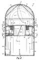
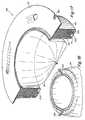
- FIG. 1is a partially cut-away perspective view of a first embodiment of a waste disposal device in accordance with the present invention with a first type of cartridge placed therein;
- FIG. 2is a cross-sectional view taken along line 2 — 2 in FIG. 1 with a second type of cartridge placed therein;
- FIG. 3is a sectional view taken along line 3 — 3 in FIG. 2 ;
- FIG. 4is a sectional view taken along line 4 — 4 in FIG. 2 , showing the gear assembly
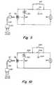
- FIG. 5is an electrical circuit diagram for use in the waste disposal device shown in FIGS. 1-4 ;
- FIG. 6is a perspective view of a second embodiment of a waste disposal device in accordance with the present invention.
- FIG. 7is a cross-sectional side view taken along line 7 — 7 in FIG. 6 ;
- FIG. 7Ais a bottom view of the bayonet-type connection along line 7 A— 7 A in FIG.7 ;
- FIG. 8is a cross-sectional plan view taken along line 8 — 8 in FIG. 6 with the cartridge removed;
- FIG. 9is a cross-sectional side view similar to FIG. 7 but showing an alternate embodiment with the cartridge removed;
- FIG. 10is an electrical circuit diagram for use in the waste disposal device shown in FIGS. 6-9 ;
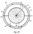
- FIG. 11is a side elevation, partly in section, of another embodiment of a cartridge of flexible tubing for use in the invention.
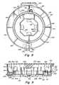
- FIG. 12is a top view of the cartridge shown in FIG. 11 ;
- FIG. 13is a bottom view of the cartridge shown in FIG. 11 ;
- FIG. 14is a perspective view of another embodiment of a cartridge of flexible tubing for use in the invention.
- FIG. 15is a perspective view of a tie upon removal from the cover of the cartridge shown in FIG. 14 ;
- FIG. 16is a perspective view of a clasp upon removal from the cover of the cartridge shown in FIG. 14 ;
- FIG. 17is a perspective, cross-sectional view of another embodiment of a cartridge of flexible tubing for use in the invention.
- FIG. 18is a perspective view of the end of the tubing of the cartridge shown in FIG. 17 after removal from the cartridge.
- the waste disposal devicesprovide for rotation of a retention unit, mechanism or member which holds a quantity of waste in and relative to a cartridge of flexible tubing which is prevented from rotated, e.g., by being held stationary.
- the flexible tubingis caused to twist above the quantity of waste thereby enclosing or encapsulating the held quantity of waste in the tubing.
- the enclosed wasteis then urged into a waste receiving chamber of the waste disposal device upon the insertion of another waste package into the device to be enclosed or in some embodiments, provisions are made to enable the enclosed waste to be drawn into the waste receiving chamber upon twisting of the flexible tubing without dependency on the subsequent insertion of another quantity of waste. In either case, repeated insertions of waste cause the formation of a chain or series of enclosed waste which can be removed from the container when the container is full or the tubing is exhausted.
- FIGS. 1-4show a first embodiment of a waste disposal device according to the present invention designated generally at 10 .
- the waste disposal device 10comprises a generally cylindrical housing or container 12 having a removable cover 14 .
- the cover 14fits snugly on an upper rim 13 of the housing 12 and has a swingable member 16 which is openable to define a waste insertion opening.
- the open position of the swingable member 16is shown in FIG. 2 in chain lines.
- the swingable member 16which is pivotally and swingably mounted to the cover 14 , is shown only by way of example. Other opening devices, or a lift-top cover, can be provided, as desired.
- the swingable member 16is pivotable about a pivot axis defined by a pivot pin at the top of the swingable member 16 and pivots between an open position to provide access to the interior of the housing 12 , and a closed position to essentially close off the interior of the housing 12 .
- a removable or replaceable cartridge 24rests on a flange 18 of the housing 12 and contains a circumferentially pleated length of flexible tubing 34 therein.
- the tubing 34is flexible and may constitute a polybag.
- the cartridge 24includes a cylindrical outer wall 26 , a lower wall 28 , an inner wall 30 and an upper wall 32 which together define a cavity for receiving the circumferentially pleated length of flexible tubing 34 .
- a ring-shaped opening 36is defined between the upper portion of the inner wall 30 and the upper wall 32 for passage of the tubing 34 therethrough, as shown in FIG. 1 .
- the inner wall 30is provided with an annular upper lip 38 over which the tubing 34 passes into a waste insertion chamber 40 defined by a cylindrical member 42 which is rotatable relative to the housing 12 (see FIG. 2 ).
- the waste insertion chamber 40is in communication with the waste insertion opening defined by the cover 14 . In use, waste is placed into the tubing 34 present in the waste insertion chamber 40 .
- the outer wall 26 of the cartridge 24includes an outwardly flared portion which overlies and rests on the flange 18 .
- the cartridge 24may be supported by constructing the annular lip 38 of the inner wall 30 to rest on the upper edge of the cylindrical member 42 . In this case however, the cylindrical member 42 rotates relative to the cartridge 24 so a low-friction supporting accommodation is desirable.
- the cartridge 24may be designed to be a single-use, disposable cartridge with a self-closing function, i.e., include a closing mechanism to enable the cartridge 24 to be closed upon itself so that it can then be pushed through the waste insertion chamber 40 into the waste storage compartment 90 defined in the housing 12 . In this manner, the end of the tubing 34 does not have to be tied or clamped closed as it would be closed upon closure of the cartridge 24 .
- Using such cartridges 24it would not be necessary to remove the cartridge 24 from the housing 12 but rather, the cartridge 24 would be placed into the waste storage compartment 90 and removed with the waste therefrom.
- the cartridge 24when the tubing 34 in the cartridge 24 is used up, the cartridge 24 may be removed from the housing 12 by first removing the cover 14 from the container 12 , and then lifting the cartridge 24 out. A new, full cartridge 24 is then placed on the flange 18 , a length of the tubing 34 from this new, full cartridge is removed, if necessary, and the removed length of tubing 34 is pressed into the waste insertion chamber 40 , and the cover 14 is then closed.
- the tubing 34is preferably sealed at the beginning end thereof (as discussed below with reference to FIGS. 11 - 18 ).
- tubing 34has an open bottom (i.e., is not sealed at the end thereof), it can be tied closed before closing the cover 14 , or some other tie or clamp mechanism can be used, such as a polybag tie, a clip, etc. to close off the open end before use.
- a rotatable retention mechanismis provided to hold the waste in the tubing 34 after its insertion into the waste insertion chamber 40 and a rotation mechanism is provided to rotate the waste when held by the retention mechanism in the waste insertion chamber 40 .
- the rotation mechanismcomprises a driving gear 54 connected to an output, drive shaft of a drive motor 56 which receives power from a battery 130 or an external power source 60 via a cable 62 (see FIG. 1 ).
- the motor 56can be solely battery operated, as desired.
- An exemplary electrical circuit diagram for the rotation mechanismis shown in FIG. 5 .
- the retention mechanismconverts the rotation of the driving gear 54 into rotation of the quantity of waste when received in the tubing 34 in the insertion waste chamber 40 defined by the cylindrical member 42 .
- the retention mechanismincludes the cylindrical member 42 and a ring gear 50 having radially, outwardly facing teeth at the lower end of the cylindrical member 42 (see FIGS. 2 and 4 ).
- the ring gear 50rests on a flange 52 of the housing 12 and is rotatable relative to the flange 52 .
- the cylindrical member 42 and ring gear 50may be formed integral with one another or as separate components and connected together.
- the axis of rotation of the ring gear 50 and the axis of rotation of the driving gear 54are parallel to one another, i.e., the ring gear 50 and the driving gear 54 both rotate in a horizontal plane.
- the ring gear 50is maintained in its position resting on flange 52 by one or more holding members 51 which are connected to the flange 52 (see FIG. 4 ).
- the holding members 51are arranged slightly spaced upwardly from the ring gear 50 to provide clearance so as to permit the ring gear 50 to rotate, while preventing the ring gear 50 from being lifted up out of the device 10 inadvertently. That is, the ring gear 50 is situated and rotates between the flange 52 and the holding members 51 (see FIG. 2 ).
- Other mechanisms for limiting the upward movement of the ring gear 51 from the flange 52instead of or in addition to the holding members 51 , can also be provided.
- a manually operable switch 64is provided to manually start the motor 56 so as to rotate drive gear 54 and in turn rotate driven ring gear 50 .
- the switch 64is connected to complete the electrical power circuit to the motor 56 . Depressing the switch 64 causes the drive shaft of the motor 56 to rotate, thereby rotating the driven ring gear 50 .
- the ring gear 50includes a disengagement member 70 thereon (see FIG. 4 ).
- the electrical systemalso includes a normally closed switch 72 which is operated by the disengagement member 70 .
- the disengagement member 70 and switch 72form part of a mechanism for automatically limiting the rotation of the retention mechanism, i.e., the cylindrical member 42 and the ring gear 50 .
- the mechanismmay be used to limit the rotation to one revolution.
- the switch 64is manually depressed to start rotation of the drive shaft of the motor 56 .
- the disengagement member 70is moved in the clockwise direction so that it no longer engages a switch operation member 73 of the switch 72 .
- the manually operated switch 64can be released, since the normally closed switch 72 will now be in the closed position so as to provide power to the motor 56 to enable the drive shaft of the motor 56 to continue to rotate, thereby continuing to drive the ring gear 50 (and cause rotation of the cylindrical member 42 ) in the clockwise direction.
- the disengagement member 70After a complete rotation of the disengagement member 70 , the disengagement member 70 again contacts the switch operation member 73 of switch 72 , and switches the normally closed switch 72 to the OPEN position, thereby interrupting power to the motor 56 (since the switch 64 was released), stopping the motor 56 and stopping the rotation of the ring gear 50 at the position shown in FIG. 4 .
- Alternative rotation mechanismcan be used in the invention which convert a manual action into limited amount of rotation of the cylindrical member 42 .
- Some rotation mechanisms which include a motive component, such as a motor,are disclosed in U.S. patent application Ser. No. 10/138,058 and can easily be adapted for use with the cylindrical member 42 . It is also possible to provide for manual rotation of the cylindrical member without the use of electronic components and a motor, for example, by connecting a handle to the cylindrical member in a similar manner as disclosed in U.S. patent application Ser. No. 10/138,058.
- the housing 12also includes a mechanism for imparting downward movement to the waste in the waste insertion chamber 40 upon rotation of the cylindrical member 42 .
- this mechanismconstitutes a pair of protruding members or fins 44 formed on the inner surface of the cylindrical member 42 which defines the waste insertion chamber 40 .
- the fins 44may be formed integral with the cylindrical member 42 or formed as separate components and connected thereto.
- the protruding fins 44are inclined so as to drive the waste material, when surrounded by tubing 34 , downward toward the bottom of the housing 12 as the cylindrical member 42 rotates (see FIG. 2 ).
- the angle R of the inclined protruding fins 44 shown in FIG. 2may be approximately 30°. However, other inclination angles may be provided, as desired.
- any number of fins 44may be provided, and the size and inclination of the fins 44 appropriately determined, to ensure that a sufficient amount of downward movement is imparted to the waste held by the fins 44 upon rotation of the cylindrical member 42 .
- the cartridge 24remains stationary since it is held on the flange 18 of the container 12 by a holding mechanism (as described below), thereby causing the flexible tubing 34 to produce a twist in the area 80 shown in FIG. 1 and essentially closing off each waste insertion from the previous waste insertion.
- a holding mechanismas described below, thereby causing the flexible tubing 34 to produce a twist in the area 80 shown in FIG. 1 and essentially closing off each waste insertion from the previous waste insertion.
- FIG. 1three enclosed or encapsulated waste insertions 82 , 84 and 86 are shown, each being closed off from the previous waste insertion by a twist 80 in the tubing 34 .
- a side door 100(partially shown in FIG. 1 ), which is pivotally connected to the housing 12 by means of, for example, hinges 102 , can be pivoted to the open position to gain access to the interior of the waste storage compartment 90 .
- the door 100is open, the chain of enclosed waste insertions 82 , 84 , 86 in the storage compartment 90 can be removed.
- waste insertions 82 , 84 , 86Prior to removal of the chain of enclose waste insertions 82 , 84 , 86 , when a self-closing, single-use cartridge is used (discussed below with reference to FIGS. 11 - 18 ), the cartridge is closed and pushed through the waste insertion chamber 40 into the waste storage compartment 90 . Thus, the chain of enclosed waste insertions 82 , 84 , 86 and cartridge are all removed from the housing 12 when the door 100 is open.
- the tubing 34 above the uppermost waste insertioncan be cut, for example with scissors.
- a cutting devicecould also be included in or on the housing 12 for this purpose.
- the tubing 34can include perforation lines or depression lines at numerous locations along the length thereof so that the tubing 34 can be cut by tearing the tubing 34 along the nearest perforation line above the last waste insertion, with an allowance of some length of tubing 34 to enable the chain of waste insertions to be closed. Closure of the chain of waste insertions may be made with a tie, a clip or some other tie or clamp mechanism. The remaining length of the tubing 34 can also be tied or clamped to seal and close off the open end of the tubing 34 before the next use in order to enable the formation of another chain of enclosed waste insertions.
- the door 100After the removal of the waste, the door 100 is closed, and a latch 104 is engaged to maintain the door 100 securely in its closed position (see FIGS. 3 and 4 ).
- the inner surface of the cylindrical wall of the housing 12 defining the waste storage compartment 90may be provided with anti-rotation ribs or protruding members 92 which are designed to abut one or more of the enclosed waste insertions 82 , 84 , 86 to prevent them from rotating, thereby improving the effectiveness of the rotation of the cylindrical member 42 to produce the twist 80 in the tubing 34 .
- the protruding members 92essentially prevent the already enclosed waste insertions 82 , 84 , 86 in the compartment 90 from rotating, thereby enhancing the effectiveness of the twist 80 produced by rotating the cylindrical member 42 . Also, the protruding members 92 prevent the waste insertions 82 , 84 , 86 from sliding around in the waste storage compartment 90 .
- one or more protruding memberscan also be formed on the bottom wall of the housing 12 defining the waste storage compartment 90 .
- Other constructions for preventing rotation of the enclosed waste insertionsmay also be provided, including those disclosed in U.S. patent application Ser. No. 10/138,058.
- a mechanismin order to provide for relative rotation between the cylindrical member 42 and the cartridge 24 , a mechanism must be provided to hold the cartridge 24 in a stationary position and thereby prevent rotation of the cartridge 24 upon rotation of the waste held by the fins 44 .
- the cartridge 24is held and prevented from rotating relative to the flange 18 on which it rests by engagement members 19 which each engage a respective cut-out portion 21 of the cartridge 24 , thereby making the cartridge 24 non-rotatable relative to the housing 12 .
- the cut-out portions 21may be formed in the flared portion of the outer wall 26 .
- FIG. 3An alternative or additional manner to hold the cartridge 24 stationary and prevent rotation thereof upon rotation of the waste when held by the fins 44 of the cylindrical member 42 would be to form a flange on the cartridge 24 and a cooperating retaining structure on the housing 12 or flange 18 thereof.
- the flange 18has additional engaging members 110 formed on an upper surface which engage a protruding flange portion or upper flange member 112 of a different cartridge 124 . This provides registration and prevents rotation of the cartridge 124 relative to the flange 18 .
- the cartridge 124is thus substantially the same as the cartridge 24 except that it has an upper flange member 112 which positioned between a pair of the members 110 , thus not requiring engagement with the members 19 shown in FIG. 1 .
- multiple cartridge holding mechanismsare provided in the same housing 12 , to the extent possible, to enable different types of cartridges to be retained.
- a single housing 12could be used with multiple types of cartridges and the waste disposal device 10 would not be limited to use with a single type of cartridge.
- a replaceable battery 130may be provided to operate the motor 56 , in addition to, or in place of, the power supply which is connected to the AC mains.
- a switch portion 63 of the socket 59is in the closed position, thereby connecting the battery 130 to supply power to the motor 56 when one of the switches 64 , 72 is closed (switch 64 being closed when manually depressed and switch 72 being normally closed but being open when the disengagement member 70 contacts the switch operation member 73 as shown in FIG. 4 ).
- Member 60may be a conventional transformer used in low voltage applications, such as the present application.
- a manually operable on/off switch 66may be arranged on the housing 12 to enable operation of the motor 56 (an electrical circuit diagram showing the placement of such a switch in a position to enable operation of the motor 56 is shown in FIG. 10 —the switch comparable to switch 66 being designated 202 therein).
- the waste disposal device 150comprises a generally cylindrical housing or container 152 defined by a wall 154 which tapers slightly inward toward a base 156 .
- the device 150includes a cover 158 pivotally connected to a projection 160 extending from an outer surface of the wall 154 .
- a removable or replaceable cartridge 162rests on ribs 164 extending inwardly from an inner surface of the wall 154 and contains a circumferentially pleated length of flexible tubing 34 therein.
- the cartridge 162includes a cylindrical outer wall 166 , a lower wall 168 , a cylindrical inner wall 170 and an upper wall 172 which together define a cavity for receiving the circumferentially pleated length of flexible tubing 34 .
- a flange 216is formed on the outer wall 166 and is attached to the upper wall 172 .
- a ring-shaped opening 174is defined between the upper portion of the inner wall 170 and the upper wall 172 for passage of the tubing 34 therethrough.
- the upper wall 172 of the cartridge 162includes a notch 182 which is designed to accommodate a step 184 in one of the ribs 164 . (The rib 164 with the step 184 does not provide support to the cartridge 162 .)
- the notch 182 and step 184serve to position the cartridge 162 in the housing 152 and also to hold the cartridge 162 stationary relative to the housing 152 and thereby prevent rotation of the cartridge 162 relative to the housing 152 .
- Other mechanisms for holding the cartridge 162 stationary in the housing 152 while preventing rotation of the cartridge 162 relative to the housing 152can also be used in the invention such as disclosed above and in U.S. patent application Ser. No. 10/138,058.
- the cartridge 162may be designed to be a single-use, disposable cartridge with a self-close function. In this manner, the end of the tubing 34 does not have to be tied or clamped closed as it would be closed upon closure of the cartridge 162 . Using such cartridges 162 , it would not be necessary to remove the cartridge 162 from the housing 152 but rather, the cartridge 162 would be placed into the waste storage compartment 90 and removed with the waste therefrom. The cartridge 162 would instead be replaced with a new, full cartridge 162 .
- the cartridge 162when the tubing 34 in the cartridge 162 is used up, the cartridge 162 may be removed from the housing 152 by pivoting the cover 158 upward and then lifting the cartridge 162 out. A new, full cartridge 162 is then placed onto the ribs 164 with the notch 182 positioned in the step 184 , a length of the tubing 34 from this new, full cartridge is removed, if necessary, and the removed length of tubing 34 is pressed into a waste insertion chamber 176 defined by a retention mechanism 178 , and the cover 158 is then closed.
- the tubing 34is preferably sealed at the beginning end thereof.
- tubing 34has an open bottom (i.e., is not sealed at the end thereof), it can be tied closed before closing the cover 158 , or some other tie or clamp mechanism can be used, such as a polybag tie, a clip, etc. to close off the open end before use.
- the cover 158includes a projection 180 removably attached to a bottom surface 158 a in the approximate shape of a truncated cone.
- the projection 180is designed to impart downward movement to waste in the waste insertion chamber 176 defined by the retention mechanism 178 , i.e., push the waste downward into the housing 152 .
- the cover 158thus has an open position in which the waste insertion chamber 176 is accessible and a closed position in which the projection 180 is partly situated in the waste insertion chamber 176 (see FIG. 7 ).
- the connection between the projection 180 and the cover 158may be a bayonet-type connection wherein a projection 186 is formed on the cover 158 with radial stops or projections 188 and slots 190 are formed on the projection 180 (see FIG. 7 A).
- the projection 180is therefore attached to the cover 158 by positioning the projection 180 such that the slots 190 align with the stops 188 and then rotating the projection 180 in one direction relative to the cover 158 . Removal of the projection 180 , e.g., for cleaning purposes, is achieved by rotating the projection 180 relative to the cover 158 in the opposite direction and then once the stops 188 align with the slots 190 , pulling the projection 180 away from the cover 158 .
- the retention mechanism 178holds and rotates the waste after its insertion into the waste insertion chamber 176 .
- the retention mechanism 178rotatably rests on a flange 194 located inside the housing 152 along the inner surface of the wall 154 , and may be integrally formed with the wall 154 .
- Flange 194can conform to the cross-sectional shape of the wall 154 .
- the ribs 164may also be formed in connection with the flange 194 .
- the retention mechanism 178is seated on the flange 194 and includes tongues or springs 196 adapted to grasp waste 82 when received by a portion of tubing 34 (see FIG. 7 ).
- Retention mechanism 178has a frame 192 including a lower planar section 192 a from which vertical walls 192 b extend upward.
- the springs 196extend inward from the vertical walls 192 and the vertical walls 192 b define an enclosure in which the springs 196 retain the waste 82 .
- a stepped section 192 cis adjacent the outer edge of the planar section 192 a and enables the frame 192 to be movably seated on the flange 194 .
- Retention mechanism 178also includes a ring gear 198 formed in connection with the stepped section 192 c .
- the ring gear 198can be formed separate from the frame 192 and connected thereto or formed integral therewith.
- the truncated cone-shaped projection 180is designed to force a waste insertion into the waste insertion chamber 176 and into engagement with the springs 196 upon closure of the cover 158 (see FIG. 7 ).
- the twist 80 in the tubing 34is thus formed between the waste insertion and the projection 180 .
- a lug 212may be formed integral with the cover 158 as shown in FIG. 9 .
- the lug 212serves the same purpose as the projection 180 .
- the vertical walls 192 bcan be constructed to provide various shaped enclosures with a variable number of springs 196 , e.g., a circular enclosure with three springs, a rectangular enclosure with four springs—one on each side and an octagonal enclosure with four springs—one on every other side (as shown in FIG. 8 ).
- springs 196e.g., a circular enclosure with three springs, a rectangular enclosure with four springs—one on each side and an octagonal enclosure with four springs—one on every other side (as shown in FIG. 8 ).
- the waste disposal device 150also includes a mechanism for rotating the retention mechanism 178 .
- the rotation mechanismincludes a driving gear 200 connected to a shaft of a drive motor 56 which receives power from a battery 130 or an external power source 60 via a cable 62 (see FIG. 10 ).
- the motor 56can be solely battery operated, as desired.
- the driving gear 200extends through an aperture formed in the flange 194 into engagement with the ring gear 198 (see FIGS. 7 and 8 ).
- a manually operable on/off switch 202is arranged on the housing 152 to enable operation of the motor 56 , i.e., enable the motor 56 to rotate its output shaft so as to rotate driving gear 200 and in turn rotate ring gear 198 and thus the frame 192 .
- the switch 202When the switch 202 is in its on position, the electrical power circuit to the motor 56 can be completed (in the manner discussed below).
- the switch 202When the switch 202 is in its off position, the electrical power circuit to the motor 56 cannot be completed regardless of whether the motor 56 is to be power by a battery 130 or via the AC mains (see FIG. 10 ).
- a manually operated, momentary on switch 204is also arranged on the housing and depressing the switch 204 causes the output shaft of the motor 56 to rotate, thereby rotating the driving gear 200 and in turn, the ring gear 198 and frame 192 .
- a disengagement member 206is arranged on the stepped portion 192 c of the frame 192 and may take the form of a cam (see FIG. 8 ).
- the electrical systemalso includes a normally closed switch 208 which is operated by the disengagement member 206 .
- the switch 204is manually depressed to start rotation of the output shaft of the motor 56 .
- the disengagement member 206is moved in the clockwise direction so that it no longer engages a switch operation member 210 of the switch 208 .
- the switch 204can be released, since the normally closed switch 204 will now be in the closed position so as to provide power to the motor 56 to enable the output shaft of the motor 56 to continue to rotate, thereby continuing to drive the ring gear 198 (and cause rotation of the frame 192 of the retention mechanism 178 ).
- the disengagement member 206After one complete revolution of the retention mechanism 178 and thus the disengagement member 206 , the disengagement member 206 again contacts the switch operation member 210 of switch 208 , and switches the normally closed switch 208 to the OPEN position, thereby interrupting power to the motor 56 (since the switch 204 was released), stopping the motor 56 and stopping the rotation of the ring gear 198 at the position shown in FIG. 8 .
- Alternative rotation mechanismcan be used in the invention which convert a manual action into limited amount of rotation of the retention mechanism 178 .
- Some rotation mechanismswhich include a motive component, such as a motor, are disclosed in U.S. patent application Ser. No. 6,612,099 and can easily be adapted for use with the retention mechanism 178 . It is also possible to provide for manual rotation of the retention member without the use of electronic components and a motor, for example, by connecting a handle to the retention member in a similar manner as disclosed in U.S. patent application Ser. No. 6,612,099.
- the cartridge 162remains stationary since it is held on the ribs 164 of the housing 152 , with the notch 182 positioned in the step 182 , thereby causing the flexible tubing 34 to produce a twist in the area 80 shown in FIG. 7 and essentially closing off each waste insertion from the previous waste insertion.
- FIG. 7four enclosed or encapsulated waste insertions 82 , 84 , 86 and 88 are shown, each being closed off from the previous waste insertion by a twist 80 in the tubing 34 .
- the side door 100(see FIG. 6 ), which is pivotally connected to the housing 152 by means of, for example, hinges 102 , can be pivoted to the open position to gain access to the interior of the waste storage compartment 90 .
- the door 100is open, the chain of enclosed waste insertions 82 , 84 , 86 , 88 in the storage compartment 90 can be removed.
- the tubing 34 above the uppermost waste insertioncan be cut, for example with scissors.
- a cutting devicecould also be included in or on the housing 152 for this purpose.
- the tubing 34can include perforation lines or depression lines at numerous locations along the length thereof so that the tubing 34 can be cut by tearing the tubing 34 along the nearest perforation line above the last waste insertion, with an allowance of some length of tubing 34 to enable the chain of waste insertions to be closed. Closure of the chain of waste insertions may be made with a tie, a clip or some other tie or clamp mechanism. The remaining length of the tubing 34 can also be tied or clamped to seal and close off the open end of the tubing 34 before the next use in order to enable the formation of another chain of enclosed waste insertions.
- the door 100After the removal of the waste (and cartridge if self-closing and single-use) and closing of the bottom end of the remaining length of tubing 34 (when the cartridge is a multi-use cartridge or a single-use cartridge with an untied beginning end), the door 100 is closed, and the latch 104 is engaged to maintain the door 100 securely in its closed position. If a new cartridge is needed, the cover 158 is pivoted upward relative to the housing 152 and the new cartridge 162 is placed on the ribs 164 with the notch 182 positioned in the step 184 .
- the inner surface of the cylindrical wall 154 of the housing 152 defining the waste storage compartment 90may be provided with anti-rotation ribs or protruding members 92 as discussed above.
- one or more protruding memberscan also be formed on the base 156 of the housing 152 .
- the base 156includes an upward curved central region 156 a which is designed to urge the enclosed waste insertions toward the wall 154 of the housing 152 and thus into engagement with the protruding members 92 .
- a replaceable battery 130may be provided to operate the motor 56 , in addition to, or in place of, the power supply which is connected to the AC mains.
- a switch portion 63 of the socket 59is in the closed position, thereby connecting the battery 130 to supply power to the motor 56 when switch 202 is closed and when one of the switches 204 , 208 is closed (switch 204 being closed when manually depressed and switch 208 being normally closed but being open when the disengagement member 206 contacts the switch operation member 210 as shown in FIG. 8 ).
- the cartridges 24 , 162 described abovemay be designed to eliminate the need to tie the tubing 34 , both at the beginning of use of the cartridge 24 , 162 and when the tubing 34 is used up and/or the waste storage compartment 90 is full.
- the rear end of the tubing 34is usually fixed to the cartridge 24 , 162 to maintain the tubing 34 in connection with the cartridge 24 , 162 .
- the cartridges 24 , 162can also be designed for single uses, i.e., contain an amount of tubing 34 to enable filling of the waste storage compartment 90 with only a single series of waste insertions. In this case, the cartridges 24 , 162 could be made shorter as they would contain less tubing than if designed for multiple uses and thus, the waste disposal devices 10 , 150 could be made shallower.
- a typical height of a single-use, disposable cartridgewould be about 3 ⁇ 4 to about 1 inch.
- FIGS. 11-18will be directed to the cartridge 162 shown in FIGS. 6 and 7 but it should be understood that the same features can be applied to the cartridges 24 shown in FIGS. 1-3 .
- the cartridge 162is constructed with the front end of tubing 34 closed, for example, by using a metal clip or clasp 214 as shown in FIGS. 11 and 13 .
- the clasp 214is secured to the front end of the tubing 34 during manufacture of the cartridge 162 so that the cartridge 162 is ready for use immediately upon purchase without requiring removal of a length of tubing and tying of the end of the removed length of tubing (as in conventional diaper pails of the “Diaper Genie”TM type described above).
- the end of the tubing 34could be closed by heat-sealing (as shown in FIG. 17 ), formed with a closed end, or sewn closed.
- the cartridge 162is provided with a closure mechanism which is effective to close and seal the rear end of tubing 34 without requiring tying of the tubing 34 .
- the closure mechanisminvolves a particular construction of the cartridge 162 with weakened regions to allow for folding of a part of the cartridge 162 onto itself.
- the upper wall 172is provided with score lines 222 , which separate approximately equal parts 172 a , 172 b of the upper wall 172 and enable the upper wall 172 to be folded about the score lines 222 , and with a mechanism to attach the folded parts 172 a , 172 b together (FIG. 12 ).
- score lines 222 on the upper wall 172other types of constructions creating a weakened portion on the upper wall 172 can also be provided, for example, providing a reduced thickness along a fold line.
- the outer, lower and inner walls 166 , 168 , 170 and flange 216are provided with slits or weakened sections 220 extending therethrough (FIG. 13 ).
- Slits 220are substantially in alignment with the score lines 222 in the upper wall 172 .
- the outer, lower and inner walls 166 , 168 , 170 and flange 216separate into two sections about the slits 220 .
- the outer, lower and inner walls 166 , 168 , 170 and flange 216may be actually be broken as the cartridge 162 is folded.
- the outer, lower and upper walls 166 , 168 , 170can be made of a material which is easily broken and score lines or slots provided to enable breaking of the casing along the score lines or slots upon folding of the cartridge 162 .
- the mechanism on the upper wall 172 which will attach the parts 172 a , 172 b thereof togethermay be of the Velcro® type whereby part 172 a includes a section of hook fasteners 218 and part 172 b includes a section of loop fasteners 224 positioned to mate with the hook fastener section 218 when the upper wall 172 is folded about the score lines 222 .
- the size and shape of the hook and loop fastener sections 218 , 224can be varied and adjusted with a view toward obtaining a sufficiently secure bond between the parts 172 a , 172 b of the upper wall 172 when the upper wall 172 is folded about the score lines 222 .
- An alternative mechanismwould be to arrange a strip of adhesive on one part 172 a with a covering pad so that removal of the covering pad would expose the adhesive which would then be folded to engage the opposite part 172 b.
- FIGS. 14-18Another alternative mechanism is shown in FIGS. 14-18 and comprises a tie 226 and a clasp 228 stamped or otherwise integrated into the upper wall 172 ′.
- Upper wall 172 ′also includes an aperture 230 on each part 172 a ′, 172 b ′ which align when the cover 172 ′ is folded.
- the tie 226 and clasp 228are removed from the upper wall 172 ′, the upper wall 172 ′ is folded about the score lines 222 and the tie 226 is inserted through the aligning apertures 230 and the clasp 228 is then attached to the tie 226 to thereby securely keep the upper wall 172 ′ in a folded state.
- the tie 226 and clasp 228can be used to tie off the open end of the tubing 34 in a conventional manner.
- FIGS. 17 and 18show a mechanism which eliminates the need to attach the parts of the upper wall 172 to one another in order to seal and close the tubing 34 .
- a drawstring 242is inserted into a channel formed at the rear edge of the tubing 34 .
- the drawstring 242is pulled from the cartridge 162 and the exposed loops can be pulled to close the end of the tubing 34 .
- the cartridge 162 , 162 ′Once the cartridge 162 , 162 ′ is folded to close and seal the rear end of the tubing 34 , it can be pushed into the waste storage compartment 90 through the waste insertion chamber 40 and the cover 158 may then be raised to enable placement of a new cartridge 162 , 162 ′ into the housing 152 .
- the waste storage compartment 90is emptied when full.
- the length of tubing 34 in the cartridge 162 , 162 ′can be selected so that the waste storage compartment 90 is full when the tubing 34 is exhausted. In this case, emptying of the device 150 and replacement of the cartridge 162 , 162 ′ would occur simultaneously.
- the upper wall 172 of the cartridges 162is provided with a notch 182 to enable engagement with the step 184 formed in one of the ribs 164 and thereby prevent rotation of the cartridge 162 .
- the upper wall 172 of the cartridgewith one or more flanges (such as in the cartridge 124 shown in FIG. 3 ) to engage with projection in the housing and thereby prevent rotation of the cartridge.
- the flange(s)could be provided instead of or in addition to the notch.
- the outer wall 166 of the cartridgewith one or more cut-out portions (such as in the cartridge 24 shown in FIGS. 1 and 3 ) to engage with engagement members in the housing and thereby prevent rotation of the cartridge.
- the cut-out portionscould be provided instead of or in addition to the notch and/or flanges.
- any of the closure mechanism for closing the front end and rear end of the tubing as shown in FIGS. 11-18can thus be applied in connection with the cartridges 24 , 124 shown in FIGS. 1-4 and the cartridge 162 shown in FIGS. 6-9 .
Landscapes
- Engineering & Computer Science (AREA)
- Mechanical Engineering (AREA)
- Environmental & Geological Engineering (AREA)
- Refuse Receptacles (AREA)
- Refuse Collection And Transfer (AREA)
Abstract
Description
Claims (65)
Priority Applications (2)
| Application Number | Priority Date | Filing Date | Title |
|---|---|---|---|
| US10/633,198US6851251B2 (en) | 2002-07-31 | 2003-07-31 | Waste disposal devices |
| US11/032,554US7114314B2 (en) | 2002-07-31 | 2005-01-10 | Waste disposal devices |
Applications Claiming Priority (2)
| Application Number | Priority Date | Filing Date | Title |
|---|---|---|---|
| US40037902P | 2002-07-31 | 2002-07-31 | |
| US10/633,198US6851251B2 (en) | 2002-07-31 | 2003-07-31 | Waste disposal devices |
Related Child Applications (1)
| Application Number | Title | Priority Date | Filing Date |
|---|---|---|---|
| US11/032,554ContinuationUS7114314B2 (en) | 2002-07-31 | 2005-01-10 | Waste disposal devices |
Publications (2)
| Publication Number | Publication Date |
|---|---|
| US20040020175A1 US20040020175A1 (en) | 2004-02-05 |
| US6851251B2true US6851251B2 (en) | 2005-02-08 |
Family
ID=31188682
Family Applications (2)
| Application Number | Title | Priority Date | Filing Date |
|---|---|---|---|
| US10/633,198Expired - LifetimeUS6851251B2 (en) | 2002-07-31 | 2003-07-31 | Waste disposal devices |
| US11/032,554Expired - Fee RelatedUS7114314B2 (en) | 2002-07-31 | 2005-01-10 | Waste disposal devices |
Family Applications After (1)
| Application Number | Title | Priority Date | Filing Date |
|---|---|---|---|
| US11/032,554Expired - Fee RelatedUS7114314B2 (en) | 2002-07-31 | 2005-01-10 | Waste disposal devices |
Country Status (5)
| Country | Link |
|---|---|
| US (2) | US6851251B2 (en) |
| EP (1) | EP1545807A2 (en) |
| AU (1) | AU2003276843A1 (en) |
| CA (1) | CA2499016A1 (en) |
| WO (1) | WO2004011164A2 (en) |
Cited By (70)
| Publication number | Priority date | Publication date | Assignee | Title |
|---|---|---|---|---|
| US20040004080A1 (en)* | 2002-04-24 | 2004-01-08 | Frank Yang | Trash can assembly |
| US20050016890A1 (en)* | 2001-06-12 | 2005-01-27 | Tannock Robert William | Spool for a waste storage device |
| US20050115207A1 (en)* | 2003-09-02 | 2005-06-02 | Chomik Richard S. | Automated twist diaper disposal apparatus |
| US20050126130A1 (en)* | 2002-07-31 | 2005-06-16 | Saniquest Industries Corporation | Waste disposal devices |
| US6931684B1 (en)* | 2004-06-16 | 2005-08-23 | Patricia H. W. Henegar | Bed having an integral refuse disposal system |
| US20050217214A1 (en)* | 2004-04-03 | 2005-10-06 | Richardson Bobbi S | Waste disposal system with flexible tubing |
| US20060248862A1 (en)* | 2005-04-25 | 2006-11-09 | International Refills Company Ltd. | Apparatus for packing disposable objects into an elongated tube of flexible material |
| US20070219425A1 (en)* | 2006-03-17 | 2007-09-20 | Moore Barrett H | Waste Disposal Device |
| USD586971S1 (en) | 2007-11-16 | 2009-02-17 | Playtex Products, Inc. | Waste disposal device |
| US20090126320A1 (en)* | 2007-11-16 | 2009-05-21 | Playtex Products, Inc. | Waste disposal devices and methods |
| US20090127260A1 (en)* | 2007-11-16 | 2009-05-21 | Playtex Products, Inc. | Waste disposal devices and methods |
| US20100005759A1 (en)* | 2008-07-14 | 2010-01-14 | Stravitz David M | Waste Disposal Devices |
| US20100005762A1 (en)* | 2008-07-14 | 2010-01-14 | Stravitz David M | Waste Disposal Devices |
| WO2010008412A1 (en) | 2008-07-14 | 2010-01-21 | Munchkin, Inc. | Waste disposal device |
| US20100089926A1 (en)* | 2006-11-16 | 2010-04-15 | Graham Keith Lacy | Waste Storage Device |
| US7743588B2 (en) | 2003-10-23 | 2010-06-29 | Sangenic International Limited | Waste storage device |
| USD619905S1 (en) | 2009-10-30 | 2010-07-20 | Munchkin, Inc. | Diaper pail bag |
| US20110056942A1 (en)* | 2009-09-10 | 2011-03-10 | Aprica Children's Products, Inc. | Waste Disposal Apparatus |
| US20110056967A1 (en)* | 2009-09-10 | 2011-03-10 | Aprica Children's Products, Inc. | Film Accommodating Cassette for Waste Disposal Apparatus |
| US20110056173A1 (en)* | 2009-09-10 | 2011-03-10 | Aprica Children's Products, Inc. | Waste Disposal Apparatus |
| USD639002S1 (en) | 2009-10-30 | 2011-05-31 | Munchkin, Inc. | Diaper pail bag |
| USD639003S1 (en) | 2009-10-30 | 2011-05-31 | Munchkin, Inc. | Diaper pail bag |
| USD639004S1 (en) | 2009-10-30 | 2011-05-31 | Munchkin, Inc. | Diaper pail bag |
| US7963414B1 (en) | 2008-12-17 | 2011-06-21 | Stravitz David M | Waste disposal device with self-closing lid |
| US8127519B2 (en) | 2008-07-14 | 2012-03-06 | Stravitz David M | Method of inserting and storing waste for disposal |
| US8235237B1 (en) | 2008-12-17 | 2012-08-07 | David M Stravitz | Waste disposal device with self-closing lid |
| US8266871B1 (en) | 2010-07-07 | 2012-09-18 | David M Stravitz | Waste disposal devices with advanced control |
| US8266870B1 (en) | 2010-07-07 | 2012-09-18 | David M Stravitz | Waste disposal devices with manual control |
| US8393489B1 (en) | 2008-12-17 | 2013-03-12 | David M Stravitz | Medical waste disposal device with self-closing lid |
| US8567157B2 (en) | 2009-10-30 | 2013-10-29 | Munchkin, Inc. | System for disposing waste packages such as diapers |
| US20130298506A1 (en)* | 2010-12-17 | 2013-11-14 | Lencon Products B.V. | Device and method for the disposal of waste |
| US8635838B2 (en) | 2009-10-30 | 2014-01-28 | Munchkin, Inc. | System for disposing waste packages such as diapers |
| US8647587B2 (en) | 2009-10-30 | 2014-02-11 | Munchkin, Inc | Powder dispensing assembly for a waste container |
| US8690017B2 (en) | 2009-10-30 | 2014-04-08 | Munchkin, Inc. | Powder dispensing assembly for a waste container |
| US8739501B2 (en) | 2009-10-30 | 2014-06-03 | Munchkin, Inc. | System for disposing waste packages such as diapers |
| US20140208499A1 (en)* | 2011-08-23 | 2014-07-31 | Dry Flush Llc | Bagging Toilet |
| US8833592B2 (en) | 2009-10-30 | 2014-09-16 | Munchkin, Inc. | System and method for disposing waste packages such as diapers |
| US8910821B1 (en) | 2013-09-23 | 2014-12-16 | David M Stravitz | Waste disposal devices with waste treatment component |
| US8973774B1 (en) | 2014-02-25 | 2015-03-10 | David M. Stravitz | Waste container with actuatable, internal bag obstruction member |
| US9056716B1 (en) | 2014-02-25 | 2015-06-16 | David M Stravitz | Waste container with actuatable, internal bag obstruction member |
| USD764136S1 (en) | 2015-11-09 | 2016-08-16 | David M Stravitz | Bag-retaining insert for waste container |
| US9434537B2 (en)* | 2014-08-29 | 2016-09-06 | Thomas E. McConnell | System and apparatus for waste disposal and changing infant-toddler behavior |
| USD766534S1 (en) | 2016-02-26 | 2016-09-13 | David M Stravitz | Bag-securing members for waste containers |
| USD767229S1 (en) | 2015-11-09 | 2016-09-20 | David M Stravitz | Bag-retaining insert for waste container |
| USD775447S1 (en) | 2016-07-06 | 2016-12-27 | David M Stravitz | Pail for use as, for example, a waste container |
| USD777394S1 (en) | 2015-11-09 | 2017-01-24 | David M Stravitz | Bag-retaining insert for waste container |
| US9555963B2 (en)* | 2014-08-29 | 2017-01-31 | Thomas E. McConnell | System and apparatus for waste disposal and changing infant-toddler behavior |
| US9555962B1 (en) | 2013-09-23 | 2017-01-31 | David M Stravitz | Waste containers with bag trapping structure |
| US9573757B1 (en) | 2013-09-23 | 2017-02-21 | David M Stravitz | Waste treatment components |
| USD780395S1 (en) | 2016-03-18 | 2017-02-28 | David M Stravitz | Waste container |
| USD783920S1 (en) | 2015-11-09 | 2017-04-11 | David M Stravitz | Bag-retaining insert for waste container |
| US9694972B1 (en) | 2016-02-26 | 2017-07-04 | David M Stravitz | Rings for securing a bag to a container |
| USD791615S1 (en) | 2016-10-05 | 2017-07-11 | David M Stravitz | Dispenser |
| US9745127B1 (en) | 2013-09-23 | 2017-08-29 | David M Stravitz | Waste containers with unitary insert |
| US9834376B1 (en) | 2016-02-26 | 2017-12-05 | David M Stravitz | Closure components for securing a bag to a container |
| US9994393B2 (en) | 2014-12-11 | 2018-06-12 | Munchkin, Inc. | Container for receiving multiple flexible bag assemblies |
| US10053283B1 (en) | 2013-09-23 | 2018-08-21 | David M Stravitz | Waste container with bag handling assembly |
| US10179697B2 (en) | 2016-01-28 | 2019-01-15 | Edgewell Personal Care Brands, Llc | Compact waste disposal device and cassette |
| US10214347B2 (en) | 2011-02-28 | 2019-02-26 | Sangenic International Limited | Waste storage device |
| US10343842B2 (en) | 2009-10-30 | 2019-07-09 | Munchkin, Inc. | System and method for disposing waste packages such as diapers |
| WO2019177763A1 (en) | 2018-03-16 | 2019-09-19 | David M Stravitz | Waste container with bag handling assembly |
| US10450133B2 (en)* | 2016-05-17 | 2019-10-22 | Huizhen Chen | Garbage can |
| US10486899B1 (en) | 2018-12-03 | 2019-11-26 | Dooli Products, LLC | Waste disposal device with bag-grabbing membrane |
| US10611564B1 (en) | 2019-01-02 | 2020-04-07 | Dooli Products, LLC | Height adjustable waste disposal device with bag-grabbing membrane |
| US10654647B2 (en) | 2016-01-28 | 2020-05-19 | Angelcare Usa, Llc | Film cassette having an ovoid shape |
| EP3659947A1 (en) | 2009-10-30 | 2020-06-03 | Munchkin, Inc. | Method of using a diaper pail assembly |
| USD895918S1 (en) | 2020-02-07 | 2020-09-08 | Dooli Products, LLC | Vertically oriented container with a lid |
| USD895919S1 (en) | 2020-02-07 | 2020-09-08 | Dooli Products, LLC | Container with a lid |
| US10889433B2 (en) | 2007-10-05 | 2021-01-12 | International Refills Company Limited | Cassette and apparatus for packing disposable objects into an elongated tube of flexible material |
| US11008162B1 (en) | 2020-02-03 | 2021-05-18 | Dooli Products, LLC | Baby and adult-safe waste container with bag handling odor control assembly |
Families Citing this family (52)
| Publication number | Priority date | Publication date | Assignee | Title |
|---|---|---|---|---|
| US7708188B2 (en)* | 2001-05-02 | 2010-05-04 | Playtex Products, Inc. | Waste disposal device including a hamper accessible through a movable door |
| US7503159B2 (en)* | 2001-05-02 | 2009-03-17 | Playtex Products, Inc. | Waste disposal device including an external actuation mechanism to operate a cartridge |
| US7958704B2 (en)* | 2001-05-02 | 2011-06-14 | Playtex Products, Inc. | Waste disposal device including a mechanism for scoring a flexible tubing dispensed from a cartridge |
| US7694493B2 (en)* | 2001-05-02 | 2010-04-13 | Playtex Products, Inc. | Waste disposal device including a geared rotating cartridge |
| US7434377B2 (en)* | 2001-05-02 | 2008-10-14 | Playtex Products, Inc. | Waste disposal device including a rotatable geared rim to operate a cartridge |
| US7146785B2 (en) | 2001-05-02 | 2006-12-12 | Stravitz David M | Waste disposal devices |
| US7503152B2 (en)* | 2001-05-02 | 2009-03-17 | Playtex Products, Inc. | Waste disposal device including rotating cartridge coupled to lid |
| US7617659B2 (en)* | 2001-05-02 | 2009-11-17 | Playtex Products, Inc. | Waste disposal device including a cartridge movable by rollers |
| US7712285B2 (en)* | 2001-05-02 | 2010-05-11 | Playtex Products, Inc. | Waste disposal device including a sensing mechanism for delaying the rotation of a cartridge |
| US8091325B2 (en)* | 2001-05-02 | 2012-01-10 | Playtex Products, Inc. | Waste disposal device including a diaphragm for twisting a flexible tubing dispensed from a cartridge |
| US7562025B2 (en)* | 2003-09-19 | 2009-07-14 | Vesta Medical, Llc | Waste sorting system with query function, and method thereof |
| US8195328B2 (en) | 2003-09-19 | 2012-06-05 | Vesta Medical, Llc | Combination disposal and dispensing apparatus and method |
| US7119689B2 (en) | 2003-09-19 | 2006-10-10 | Vesta Medical, Llc | System and method for sorting medical waste for disposal |
| US7660724B2 (en) | 2003-09-19 | 2010-02-09 | Vesta Medical, Llc | Waste sorting system utilizing removable liners |
| GB2444868B (en)* | 2004-09-02 | 2008-12-03 | Playtex Products Inc | Waste disposal device |
| GB2450438B (en)* | 2004-09-02 | 2009-04-01 | Playtex Products Inc | Cartridge for a waste disposal device |
| WO2006029038A2 (en)* | 2004-09-02 | 2006-03-16 | Playtex Products, Inc. | Waste disposal apparatus |
| GB2420994B (en)* | 2004-12-10 | 2009-03-11 | Acco Uk Ltd | Compacting device |
| GB2427838A (en)* | 2005-07-01 | 2007-01-10 | Acco Uk Ltd | A shredder including a compactor plate that forms part of a waste bag support mechanism |
| DE202005015117U1 (en)* | 2005-09-24 | 2007-02-15 | Melitta Haushaltsprodukte Gmbh & Co. Kg | Container for temporary storage of soiled nappies, comprises mechanism for creation of odor barrier |
| US20080272140A1 (en)* | 2007-05-04 | 2008-11-06 | Playtex Products, Inc. | Cassette for dispensing flexible tubing therefrom |
| US20090120825A1 (en)* | 2007-11-13 | 2009-05-14 | Marcille Faye Ruman | Sustainability in personal care product sales |
| US20090120816A1 (en)* | 2007-11-13 | 2009-05-14 | Marcille Faye Ruman | Sustainability in personal care product packaging |
| US20090120834A1 (en)* | 2007-11-13 | 2009-05-14 | Kimberly-Clark Worldwide, Inc. | Sustainability in personal care product retailing |
| PL2077297T3 (en) | 2008-01-02 | 2012-10-31 | Flexopack Sa | PVDC formulation and heat shrinkable film |
| US8087532B2 (en)* | 2008-01-18 | 2012-01-03 | Brown Newman, L.L.C. | Waste container |
| US20090197231A1 (en)* | 2008-02-06 | 2009-08-06 | Paula Mary Sosalla | Toilet training using absorbent article packaging |
| JP2011520731A (en)* | 2008-05-19 | 2011-07-21 | サンジェニック・インターナショナル・リミテッド | Waste storage device |
| US8474642B2 (en)* | 2008-07-22 | 2013-07-02 | Baby Trend Inc. | Diaper disposal container |
| GB0902471D0 (en)* | 2009-02-13 | 2009-04-01 | Sangenic International Ltd | Waste storage device |
| JP5486338B2 (en)* | 2009-09-10 | 2014-05-07 | アップリカ・チルドレンズプロダクツ株式会社 | Waste disposal equipment |
| US20110099945A1 (en)* | 2009-10-30 | 2011-05-05 | Munchkin, Inc. | System and method for disposing waste packages such as diapers |
| US20110101014A1 (en)* | 2009-11-04 | 2011-05-05 | Baby Trend Inc. | Diaper disposal container |
| DE202011110798U1 (en) | 2011-05-03 | 2016-08-09 | Flexopack S.A. | Waste packaging system and foil |
| EP2535279B1 (en) | 2011-06-16 | 2016-11-16 | Flexopack S.A. | Waste packaging system and film |
| EP2597057B1 (en)* | 2011-11-23 | 2018-09-26 | Flexopack S.A. | Waste packing system with fusion seal apparatus |
| US9604430B2 (en) | 2012-02-08 | 2017-03-28 | Flexopack S.A. | Thin film for waste packing cassettes |
| US9598207B2 (en)* | 2012-03-05 | 2017-03-21 | International Refills Company Ltd | Waste-disposal device |
| NL1039491C2 (en)* | 2012-03-26 | 2013-09-30 | Sanalife B V | DEVICE FOR COLLECTING POLLUTED OBJECTS. |
| US10053282B2 (en) | 2012-10-24 | 2018-08-21 | Munchkin, Inc. | Cassette for dispensing pleated tubing |
| USD1077510S1 (en) | 2019-11-06 | 2025-06-03 | Munchkin, Inc. | Cassette |
| USD695541S1 (en) | 2012-10-24 | 2013-12-17 | Munchkin, Inc. | Cassette |
| US11414266B2 (en) | 2012-10-24 | 2022-08-16 | Munchkin, Inc. | Cassette for dispensing pleated tubing |
| US9962227B2 (en) | 2013-03-01 | 2018-05-08 | Lars Andre Slaateng | Container for disposal of solid pharmaceuticals and a use of a container |
| PL2813362T3 (en) | 2013-06-14 | 2020-05-18 | Flexopack S.A. | Heat shrinkable film |
| AU2015258191B2 (en) | 2014-11-19 | 2020-02-27 | Flexopack S.A. | Oven skin packaging process |
| GB2547595B (en)* | 2014-12-04 | 2019-08-21 | Munchkin Inc | Cassette for dispensing pleated tubing |
| HUE071156T2 (en) | 2015-06-15 | 2025-08-28 | Angelcare Canada Inc | Cassette for placing waste materials in an elongated flexible tube |
| EP3501822A1 (en) | 2017-12-22 | 2019-06-26 | Flexopack S.A. | Fibc liner film |
| AU2021357170A1 (en)* | 2020-10-05 | 2023-05-25 | Angelcare Canada Inc. | Waste disposal device and film dispensing cassette |
| WO2022151117A1 (en)* | 2021-01-14 | 2022-07-21 | 姚爱平 | Garbage can, can cover, and rotary packing mechanism |
| CN114620370A (en)* | 2022-02-11 | 2022-06-14 | 宁波金瓴管理咨询有限公司 | Peculiar smell prevention garbage can cover and garbage can |
Citations (25)
| Publication number | Priority date | Publication date | Assignee | Title |
|---|---|---|---|---|
| US3779157A (en)* | 1971-04-29 | 1973-12-18 | T Ross | Receptacle for waste material |
| US4162602A (en) | 1976-11-15 | 1979-07-31 | Windmoller & Holscher | Method and apparatus for filling and closing large sacks |
| US4561563A (en) | 1984-08-10 | 1985-12-31 | Woods David E | Insulated cooler for beverage containers |
| US4760784A (en) | 1987-07-15 | 1988-08-02 | Tennessee Valley Authority | Compacting plate locking device used for packaging expansible material |
| US4869049A (en) | 1987-03-05 | 1989-09-26 | Process Improvements Limited | Apparatus and methods for using packs of flexible tubing in packaging |
| US5120454A (en)* | 1991-01-15 | 1992-06-09 | Resourceful Environmental Ideas, Inc. | Covers for liquid waste receptacles with straining capability |
| US5125526A (en)* | 1991-11-21 | 1992-06-30 | Sumanis Arnold J | Waste receptacle with interior bag that is opened and closed automatically |
| US5183157A (en) | 1991-10-01 | 1993-02-02 | Darden Louis R | Plastic bag dispensing system |
| US5184575A (en) | 1989-06-02 | 1993-02-09 | Reinartz Johann O | Sanitary facility for cats |
| US5520303A (en)* | 1994-01-28 | 1996-05-28 | Safety 1St, Inc. | Diaper pail |
| US5535913A (en)* | 1994-10-20 | 1996-07-16 | Fisher-Price, Inc. | Odorless container |
| US5590512A (en) | 1994-08-26 | 1997-01-07 | Melrose Products Limited | Apparatus for using packs of flexible tubing in packaging |
| US5642810A (en) | 1996-01-02 | 1997-07-01 | Carlisle Plastics, Inc. | Container/dispenser for rolled plastic bags |
| US5655680A (en) | 1994-10-20 | 1997-08-12 | Fisher Price, Inc. | Odorless container |
| US5671847A (en) | 1994-10-27 | 1997-09-30 | Pedersen; Constance Rebecca | Trash bag dispenser |
| US5813200A (en) | 1996-12-17 | 1998-09-29 | Mondial Industries, Ltd. | Packaging and disposal system |
| US5884556A (en) | 1997-09-30 | 1999-03-23 | Koncept Kreations, Ltd. | Trash handling device |
| US6000323A (en) | 1998-07-23 | 1999-12-14 | Schlegel; Dean J. | Trash compacting method and apparatus |
| US6120743A (en)* | 1998-03-17 | 2000-09-19 | Papari; Joanne | Hygienic sanitary napkin disposal system |
| US6128890A (en) | 1998-02-09 | 2000-10-10 | Sangenic International Limited | Waste storage device |
| US6370847B1 (en) | 2000-10-02 | 2002-04-16 | Tim Allan Nygaard Jensen | Sealable diaper-disposal system and method |
| US6453640B1 (en) | 1999-07-28 | 2002-09-24 | Max Co., Ltd. | Bag binding machine |
| WO2002083525A1 (en) | 2001-04-10 | 2002-10-24 | Playtex Products, Inc. | Waste storage device |
| US20020162304A1 (en) | 2001-05-02 | 2002-11-07 | Saniquest Industries Corp. | Waste disposal devices |
| US20030213804A1 (en) | 2002-04-17 | 2003-11-20 | Chomik Richard S. | Disposable cassette for incremental withdrawal of tubular plastic with malodor-counteractant capacity |
Family Cites Families (4)
| Publication number | Priority date | Publication date | Assignee | Title |
|---|---|---|---|---|
| US2271918A (en)* | 1939-08-12 | 1942-02-03 | Glowka Martin | Sanitary silent garbage can |
| JPH06213660A (en)* | 1993-01-19 | 1994-08-05 | Aisin Seiki Co Ltd | Detecting method for approximate straight line of image |
| US5884323A (en)* | 1995-10-13 | 1999-03-16 | 3Com Corporation | Extendible method and apparatus for synchronizing files on two different computer systems |
| US6851251B2 (en)* | 2002-07-31 | 2005-02-08 | Saniquest Industries Corp. | Waste disposal devices |
- 2003
- 2003-07-31USUS10/633,198patent/US6851251B2/ennot_activeExpired - Lifetime
- 2003-07-31CACA002499016Apatent/CA2499016A1/ennot_activeAbandoned
- 2003-07-31EPEP03772185Apatent/EP1545807A2/ennot_activeWithdrawn
- 2003-07-31AUAU2003276843Apatent/AU2003276843A1/ennot_activeAbandoned
- 2003-07-31WOPCT/US2003/024204patent/WO2004011164A2/ennot_activeApplication Discontinuation
- 2005
- 2005-01-10USUS11/032,554patent/US7114314B2/ennot_activeExpired - Fee Related
Patent Citations (28)
| Publication number | Priority date | Publication date | Assignee | Title |
|---|---|---|---|---|
| US3779157A (en)* | 1971-04-29 | 1973-12-18 | T Ross | Receptacle for waste material |
| US4162602A (en) | 1976-11-15 | 1979-07-31 | Windmoller & Holscher | Method and apparatus for filling and closing large sacks |
| US4561563A (en) | 1984-08-10 | 1985-12-31 | Woods David E | Insulated cooler for beverage containers |
| US4869049A (en) | 1987-03-05 | 1989-09-26 | Process Improvements Limited | Apparatus and methods for using packs of flexible tubing in packaging |
| US4760784A (en) | 1987-07-15 | 1988-08-02 | Tennessee Valley Authority | Compacting plate locking device used for packaging expansible material |
| US5184575A (en) | 1989-06-02 | 1993-02-09 | Reinartz Johann O | Sanitary facility for cats |
| US5120454A (en)* | 1991-01-15 | 1992-06-09 | Resourceful Environmental Ideas, Inc. | Covers for liquid waste receptacles with straining capability |
| US5183157A (en) | 1991-10-01 | 1993-02-02 | Darden Louis R | Plastic bag dispensing system |
| US5125526A (en)* | 1991-11-21 | 1992-06-30 | Sumanis Arnold J | Waste receptacle with interior bag that is opened and closed automatically |
| US5520303A (en)* | 1994-01-28 | 1996-05-28 | Safety 1St, Inc. | Diaper pail |
| US5590512A (en) | 1994-08-26 | 1997-01-07 | Melrose Products Limited | Apparatus for using packs of flexible tubing in packaging |
| US5535913A (en)* | 1994-10-20 | 1996-07-16 | Fisher-Price, Inc. | Odorless container |
| US5655680A (en) | 1994-10-20 | 1997-08-12 | Fisher Price, Inc. | Odorless container |
| US5671847A (en) | 1994-10-27 | 1997-09-30 | Pedersen; Constance Rebecca | Trash bag dispenser |
| US5642810A (en) | 1996-01-02 | 1997-07-01 | Carlisle Plastics, Inc. | Container/dispenser for rolled plastic bags |
| US6170240B1 (en) | 1996-12-17 | 2001-01-09 | Playtex Products, Inc. | Packaging and disposal system |
| US5813200A (en) | 1996-12-17 | 1998-09-29 | Mondial Industries, Ltd. | Packaging and disposal system |
| US5884556A (en) | 1997-09-30 | 1999-03-23 | Koncept Kreations, Ltd. | Trash handling device |
| US6128890A (en) | 1998-02-09 | 2000-10-10 | Sangenic International Limited | Waste storage device |
| US6120743A (en)* | 1998-03-17 | 2000-09-19 | Papari; Joanne | Hygienic sanitary napkin disposal system |
| US6000323A (en) | 1998-07-23 | 1999-12-14 | Schlegel; Dean J. | Trash compacting method and apparatus |
| US6453640B1 (en) | 1999-07-28 | 2002-09-24 | Max Co., Ltd. | Bag binding machine |
| US6370847B1 (en) | 2000-10-02 | 2002-04-16 | Tim Allan Nygaard Jensen | Sealable diaper-disposal system and method |
| WO2002083525A1 (en) | 2001-04-10 | 2002-10-24 | Playtex Products, Inc. | Waste storage device |
| US20020162304A1 (en) | 2001-05-02 | 2002-11-07 | Saniquest Industries Corp. | Waste disposal devices |
| US6612099B2 (en) | 2001-05-02 | 2003-09-02 | Saniquest Industries Corp. | Waste disposal devices including cartridge of flexible tubing |
| US20030208995A1 (en) | 2001-05-02 | 2003-11-13 | Saniquest Industries Corp. | Waste disposal devices including cartridge of flexible tubing |
| US20030213804A1 (en) | 2002-04-17 | 2003-11-20 | Chomik Richard S. | Disposable cassette for incremental withdrawal of tubular plastic with malodor-counteractant capacity |
Cited By (107)
| Publication number | Priority date | Publication date | Assignee | Title |
|---|---|---|---|---|
| US9718614B2 (en) | 2001-04-10 | 2017-08-01 | Edgewell Personal Care Brands, Llc. | Waste storage device |
| US10618728B2 (en) | 2001-04-10 | 2020-04-14 | Angelcare Usa, Llc | Waste storage device |
| US20050016890A1 (en)* | 2001-06-12 | 2005-01-27 | Tannock Robert William | Spool for a waste storage device |
| US8484936B2 (en)* | 2001-06-12 | 2013-07-16 | Sangenic International Limited | Spool for a waste storage device |
| US20040004080A1 (en)* | 2002-04-24 | 2004-01-08 | Frank Yang | Trash can assembly |
| US7374060B2 (en)* | 2002-04-24 | 2008-05-20 | Simplehuman Llc | Trash can assembly |
| US7114314B2 (en)* | 2002-07-31 | 2006-10-03 | Saniquest Industries Corp. | Waste disposal devices |
| US20050126130A1 (en)* | 2002-07-31 | 2005-06-16 | Saniquest Industries Corporation | Waste disposal devices |
| US7594376B2 (en)* | 2003-09-02 | 2009-09-29 | Playtex Products, Inc. | Automated twist diaper disposal apparatus |
| US7707808B2 (en) | 2003-09-02 | 2010-05-04 | Playtex Products, Inc. | Cassette for an automated waste disposal device |
| US9102467B2 (en) | 2003-09-02 | 2015-08-11 | Eveready Battery Company, Inc. | Waste storage device |
| US20050115207A1 (en)* | 2003-09-02 | 2005-06-02 | Chomik Richard S. | Automated twist diaper disposal apparatus |
| US20060237461A1 (en)* | 2003-09-02 | 2006-10-26 | Playtex Products, Inc. | Waste storage device |
| US20070157582A1 (en)* | 2003-09-02 | 2007-07-12 | Playtex Products, Inc. | Cassette for an automated waste disposal device |
| US7743588B2 (en) | 2003-10-23 | 2010-06-29 | Sangenic International Limited | Waste storage device |
| US10669095B2 (en) | 2003-10-23 | 2020-06-02 | Sangenic International Ltd. | Waste storage device |
| US20050217214A1 (en)* | 2004-04-03 | 2005-10-06 | Richardson Bobbi S | Waste disposal system with flexible tubing |
| US6993891B2 (en)* | 2004-04-03 | 2006-02-07 | Bobbi Sue Richardson | Waste disposal system with flexible tubing |
| US20050278843A1 (en)* | 2004-06-16 | 2005-12-22 | Henegar Patricia H W | Integral refuse disposal system |
| US7080418B2 (en) | 2004-06-16 | 2006-07-25 | Henegar Patricia H W | Integral refuse disposal system |
| US6931684B1 (en)* | 2004-06-16 | 2005-08-23 | Patricia H. W. Henegar | Bed having an integral refuse disposal system |
| US7406814B2 (en) | 2005-04-25 | 2008-08-05 | International Refills Company Ltd. | Apparatus for packing disposable objects into an elongated tube of flexible material |
| US20060248862A1 (en)* | 2005-04-25 | 2006-11-09 | International Refills Company Ltd. | Apparatus for packing disposable objects into an elongated tube of flexible material |
| WO2007071054A1 (en)* | 2005-12-23 | 2007-06-28 | International Refills Company Limited | Apparatus for packing disposable objects into an elongated tube of flexible material |
| US20070219425A1 (en)* | 2006-03-17 | 2007-09-20 | Moore Barrett H | Waste Disposal Device |
| US20100089926A1 (en)* | 2006-11-16 | 2010-04-15 | Graham Keith Lacy | Waste Storage Device |
| US8662337B2 (en) | 2006-11-16 | 2014-03-04 | Sangenic International Limited | Waste storage device |
| US8783499B2 (en) | 2006-11-16 | 2014-07-22 | Sangenic International Limited | Waste storage device |
| US20110232240A1 (en)* | 2006-11-16 | 2011-09-29 | Graham Keith Lacy | Waste Storage Device |
| US12404096B2 (en) | 2007-10-05 | 2025-09-02 | International Refills Company Limited | Cassette and apparatus for packing disposable objects into an elongated tube of flexible material |
| US11772888B2 (en) | 2007-10-05 | 2023-10-03 | International Refills Company Limited | Cassette and apparatus for packing disposable objects into an elongated tube of flexible material |
| US11383925B2 (en) | 2007-10-05 | 2022-07-12 | International Refills Company Limited | Cassette and apparatus for packing disposable objects into an elongated tube of flexible material |
| US10889433B2 (en) | 2007-10-05 | 2021-01-12 | International Refills Company Limited | Cassette and apparatus for packing disposable objects into an elongated tube of flexible material |
| US20090127260A1 (en)* | 2007-11-16 | 2009-05-21 | Playtex Products, Inc. | Waste disposal devices and methods |
| USD586971S1 (en) | 2007-11-16 | 2009-02-17 | Playtex Products, Inc. | Waste disposal device |
| US8613371B2 (en) | 2007-11-16 | 2013-12-24 | Eveready Battery Company, Inc. | Waste disposal devices for storage of waste in an inner storage area and methods |
| US9493302B2 (en) | 2007-11-16 | 2016-11-15 | Edgewell Personal Care Brands, Llc | Waste disposal services and methods |
| US20090126320A1 (en)* | 2007-11-16 | 2009-05-21 | Playtex Products, Inc. | Waste disposal devices and methods |
| US8127519B2 (en) | 2008-07-14 | 2012-03-06 | Stravitz David M | Method of inserting and storing waste for disposal |
| US8215089B2 (en) | 2008-07-14 | 2012-07-10 | David Stravitz | Waste disposal devices |
| US20100005762A1 (en)* | 2008-07-14 | 2010-01-14 | Stravitz David M | Waste Disposal Devices |
| US20100005759A1 (en)* | 2008-07-14 | 2010-01-14 | Stravitz David M | Waste Disposal Devices |
| WO2010008412A1 (en) | 2008-07-14 | 2010-01-21 | Munchkin, Inc. | Waste disposal device |
| US8235237B1 (en) | 2008-12-17 | 2012-08-07 | David M Stravitz | Waste disposal device with self-closing lid |
| US8393489B1 (en) | 2008-12-17 | 2013-03-12 | David M Stravitz | Medical waste disposal device with self-closing lid |
| US7963414B1 (en) | 2008-12-17 | 2011-06-21 | Stravitz David M | Waste disposal device with self-closing lid |
| CN102020084A (en)* | 2009-09-10 | 2011-04-20 | 爱普力卡幼儿产品株式会社 | Film accommodating cassette for waste disposal apparatus |
| CN102020085A (en)* | 2009-09-10 | 2011-04-20 | 爱普力卡幼儿产品株式会社 | Waste disposal apparatus |
| US20110056173A1 (en)* | 2009-09-10 | 2011-03-10 | Aprica Children's Products, Inc. | Waste Disposal Apparatus |
| US20110056967A1 (en)* | 2009-09-10 | 2011-03-10 | Aprica Children's Products, Inc. | Film Accommodating Cassette for Waste Disposal Apparatus |
| US20110056942A1 (en)* | 2009-09-10 | 2011-03-10 | Aprica Children's Products, Inc. | Waste Disposal Apparatus |
| US8739501B2 (en) | 2009-10-30 | 2014-06-03 | Munchkin, Inc. | System for disposing waste packages such as diapers |
| USD639003S1 (en) | 2009-10-30 | 2011-05-31 | Munchkin, Inc. | Diaper pail bag |
| US8567157B2 (en) | 2009-10-30 | 2013-10-29 | Munchkin, Inc. | System for disposing waste packages such as diapers |
| US8647587B2 (en) | 2009-10-30 | 2014-02-11 | Munchkin, Inc | Powder dispensing assembly for a waste container |
| US9714138B2 (en) | 2009-10-30 | 2017-07-25 | Munchkin Inc. | Method for disposing waste packages such as diapers |
| US8833592B2 (en) | 2009-10-30 | 2014-09-16 | Munchkin, Inc. | System and method for disposing waste packages such as diapers |
| US10343842B2 (en) | 2009-10-30 | 2019-07-09 | Munchkin, Inc. | System and method for disposing waste packages such as diapers |
| EP3659947A1 (en) | 2009-10-30 | 2020-06-03 | Munchkin, Inc. | Method of using a diaper pail assembly |
| USD639004S1 (en) | 2009-10-30 | 2011-05-31 | Munchkin, Inc. | Diaper pail bag |
| US8635838B2 (en) | 2009-10-30 | 2014-01-28 | Munchkin, Inc. | System for disposing waste packages such as diapers |
| US8690017B2 (en) | 2009-10-30 | 2014-04-08 | Munchkin, Inc. | Powder dispensing assembly for a waste container |
| USD639002S1 (en) | 2009-10-30 | 2011-05-31 | Munchkin, Inc. | Diaper pail bag |
| USD619905S1 (en) | 2009-10-30 | 2010-07-20 | Munchkin, Inc. | Diaper pail bag |
| US8266871B1 (en) | 2010-07-07 | 2012-09-18 | David M Stravitz | Waste disposal devices with advanced control |
| US8266870B1 (en) | 2010-07-07 | 2012-09-18 | David M Stravitz | Waste disposal devices with manual control |
| US20130298506A1 (en)* | 2010-12-17 | 2013-11-14 | Lencon Products B.V. | Device and method for the disposal of waste |
| US8752723B2 (en)* | 2010-12-17 | 2014-06-17 | Lencon Products B.V. | Waste disposal device having tubular film |
| US10214347B2 (en) | 2011-02-28 | 2019-02-26 | Sangenic International Limited | Waste storage device |
| US9345369B2 (en)* | 2011-08-23 | 2016-05-24 | Dry Flush Llc | Bagging toilet |
| US20140208499A1 (en)* | 2011-08-23 | 2014-07-31 | Dry Flush Llc | Bagging Toilet |
| US9745127B1 (en) | 2013-09-23 | 2017-08-29 | David M Stravitz | Waste containers with unitary insert |
| US9181028B1 (en) | 2013-09-23 | 2015-11-10 | David M Stravitz | Waste treatment component |
| US9555962B1 (en) | 2013-09-23 | 2017-01-31 | David M Stravitz | Waste containers with bag trapping structure |
| US9573757B1 (en) | 2013-09-23 | 2017-02-21 | David M Stravitz | Waste treatment components |
| US8910821B1 (en) | 2013-09-23 | 2014-12-16 | David M Stravitz | Waste disposal devices with waste treatment component |
| US10053283B1 (en) | 2013-09-23 | 2018-08-21 | David M Stravitz | Waste container with bag handling assembly |
| US9994392B1 (en) | 2013-09-23 | 2018-06-12 | David M Stravitz | Unitary insert for waste containers |
| US8973774B1 (en) | 2014-02-25 | 2015-03-10 | David M. Stravitz | Waste container with actuatable, internal bag obstruction member |
| US9056716B1 (en) | 2014-02-25 | 2015-06-16 | David M Stravitz | Waste container with actuatable, internal bag obstruction member |
| US9555963B2 (en)* | 2014-08-29 | 2017-01-31 | Thomas E. McConnell | System and apparatus for waste disposal and changing infant-toddler behavior |
| US9434537B2 (en)* | 2014-08-29 | 2016-09-06 | Thomas E. McConnell | System and apparatus for waste disposal and changing infant-toddler behavior |
| US10086996B2 (en) | 2014-12-11 | 2018-10-02 | Munchkin, Inc. | Container for receiving multiple flexible bag assemblies |
| US10053284B2 (en) | 2014-12-11 | 2018-08-21 | Munchkin, Inc. | Container for receiving multiple flexible bag assemblies |
| US9994393B2 (en) | 2014-12-11 | 2018-06-12 | Munchkin, Inc. | Container for receiving multiple flexible bag assemblies |
| USD767229S1 (en) | 2015-11-09 | 2016-09-20 | David M Stravitz | Bag-retaining insert for waste container |
| USD783920S1 (en) | 2015-11-09 | 2017-04-11 | David M Stravitz | Bag-retaining insert for waste container |
| USD764136S1 (en) | 2015-11-09 | 2016-08-16 | David M Stravitz | Bag-retaining insert for waste container |
| USD777394S1 (en) | 2015-11-09 | 2017-01-24 | David M Stravitz | Bag-retaining insert for waste container |
| US10836573B2 (en) | 2016-01-28 | 2020-11-17 | Angelcare Usa, Llc | Compact waste disposal device and cassette |
| US10179697B2 (en) | 2016-01-28 | 2019-01-15 | Edgewell Personal Care Brands, Llc | Compact waste disposal device and cassette |
| US10654647B2 (en) | 2016-01-28 | 2020-05-19 | Angelcare Usa, Llc | Film cassette having an ovoid shape |
| USD797393S1 (en) | 2016-02-26 | 2017-09-12 | David M Stravitz | Bag-securing member for waste containers |
| US9834376B1 (en) | 2016-02-26 | 2017-12-05 | David M Stravitz | Closure components for securing a bag to a container |
| USD766534S1 (en) | 2016-02-26 | 2016-09-13 | David M Stravitz | Bag-securing members for waste containers |
| USD815384S1 (en) | 2016-02-26 | 2018-04-10 | David M Stravitz | Bag-securing member for waste container |
| US9694972B1 (en) | 2016-02-26 | 2017-07-04 | David M Stravitz | Rings for securing a bag to a container |
| USD780395S1 (en) | 2016-03-18 | 2017-02-28 | David M Stravitz | Waste container |
| US10450133B2 (en)* | 2016-05-17 | 2019-10-22 | Huizhen Chen | Garbage can |
| USD775447S1 (en) | 2016-07-06 | 2016-12-27 | David M Stravitz | Pail for use as, for example, a waste container |
| USD791615S1 (en) | 2016-10-05 | 2017-07-11 | David M Stravitz | Dispenser |
| WO2019177763A1 (en) | 2018-03-16 | 2019-09-19 | David M Stravitz | Waste container with bag handling assembly |
| US10486899B1 (en) | 2018-12-03 | 2019-11-26 | Dooli Products, LLC | Waste disposal device with bag-grabbing membrane |
| US10611564B1 (en) | 2019-01-02 | 2020-04-07 | Dooli Products, LLC | Height adjustable waste disposal device with bag-grabbing membrane |
| US11008162B1 (en) | 2020-02-03 | 2021-05-18 | Dooli Products, LLC | Baby and adult-safe waste container with bag handling odor control assembly |
| USD895918S1 (en) | 2020-02-07 | 2020-09-08 | Dooli Products, LLC | Vertically oriented container with a lid |
| USD895919S1 (en) | 2020-02-07 | 2020-09-08 | Dooli Products, LLC | Container with a lid |
Also Published As
| Publication number | Publication date |
|---|---|
| AU2003276843A8 (en) | 2004-02-16 |
| US7114314B2 (en) | 2006-10-03 |
| EP1545807A2 (en) | 2005-06-29 |
| WO2004011164A2 (en) | 2004-02-05 |
| AU2003276843A1 (en) | 2004-02-16 |
| CA2499016A1 (en) | 2004-02-05 |
| WO2004011164A3 (en) | 2004-08-05 |
| US20040020175A1 (en) | 2004-02-05 |
| US20050126130A1 (en) | 2005-06-16 |
Similar Documents
| Publication | Publication Date | Title |
|---|---|---|
| US6851251B2 (en) | Waste disposal devices | |
| US7434377B2 (en) | Waste disposal device including a rotatable geared rim to operate a cartridge | |
| US7146785B2 (en) | Waste disposal devices | |
| US7503159B2 (en) | Waste disposal device including an external actuation mechanism to operate a cartridge | |
| US7958704B2 (en) | Waste disposal device including a mechanism for scoring a flexible tubing dispensed from a cartridge | |
| US7316100B2 (en) | Waste disposal device including a film cutting and sealing device | |
| US7503152B2 (en) | Waste disposal device including rotating cartridge coupled to lid | |
| US7617659B2 (en) | Waste disposal device including a cartridge movable by rollers | |
| US6612099B2 (en) | Waste disposal devices including cartridge of flexible tubing | |
| US7694493B2 (en) | Waste disposal device including a geared rotating cartridge | |
| US7708188B2 (en) | Waste disposal device including a hamper accessible through a movable door | |
| US7712285B2 (en) | Waste disposal device including a sensing mechanism for delaying the rotation of a cartridge | |
| US8091325B2 (en) | Waste disposal device including a diaphragm for twisting a flexible tubing dispensed from a cartridge | |
| US20050193692A1 (en) | Waste disposal device including rotating cartridge coupled to hinged lid | |
| WO2006029038A2 (en) | Waste disposal apparatus | |
| GB2446740A (en) | A waste disposal device | |
| GB2444868A (en) | Waste disposal device with a rotation mechanism | |
| AU2002259134A1 (en) | Waste disposal devices |
Legal Events
| Date | Code | Title | Description |
|---|---|---|---|
| AS | Assignment | Owner name:SANIQUEST INDUSTRIES CORP., NEW YORK Free format text:ASSIGNMENT OF ASSIGNORS INTEREST;ASSIGNOR:STRAVITZ, DAVID M.;REEL/FRAME:014334/0930 Effective date:20030730 | |
| FEPP | Fee payment procedure | Free format text:PAYOR NUMBER ASSIGNED (ORIGINAL EVENT CODE: ASPN); ENTITY STATUS OF PATENT OWNER: SMALL ENTITY | |
| FPAY | Fee payment | Year of fee payment:4 | |
| AS | Assignment | Owner name:MUNCHKIN, INC., CALIFORNIA Free format text:ASSIGNMENT OF ASSIGNORS INTEREST;ASSIGNOR:SANIQUEST INDUSTRIES CORP.;REEL/FRAME:021462/0586 Effective date:20080902 | |
| FPAY | Fee payment | Year of fee payment:8 | |
| SULP | Surcharge for late payment | Year of fee payment:7 | |
| REMI | Maintenance fee reminder mailed | ||
| FEPP | Fee payment procedure | Free format text:PETITION RELATED TO MAINTENANCE FEES GRANTED (ORIGINAL EVENT CODE: PMFG); ENTITY STATUS OF PATENT OWNER: SMALL ENTITY Free format text:PETITION RELATED TO MAINTENANCE FEES FILED (ORIGINAL EVENT CODE: PMFP); ENTITY STATUS OF PATENT OWNER: SMALL ENTITY | |
| LAPS | Lapse for failure to pay maintenance fees | ||
| REIN | Reinstatement after maintenance fee payment confirmed | ||
| FP | Lapsed due to failure to pay maintenance fee | Effective date:20170208 | |
| PRDP | Patent reinstated due to the acceptance of a late maintenance fee | Effective date:20170810 | |
| FPAY | Fee payment | Year of fee payment:12 | |
| SULP | Surcharge for late payment | ||
| STCF | Information on status: patent grant | Free format text:PATENTED CASE |