US6850704B1 - Low-overhead fault-tolerance techniques for optical and other cross-connect systems - Google Patents
Low-overhead fault-tolerance techniques for optical and other cross-connect systemsDownload PDFInfo
- Publication number
- US6850704B1 US6850704B1US09/614,436US61443600AUS6850704B1US 6850704 B1US6850704 B1US 6850704B1US 61443600 AUS61443600 AUS 61443600AUS 6850704 B1US6850704 B1US 6850704B1
- Authority
- US
- United States
- Prior art keywords
- code
- output
- input
- check
- signal
- Prior art date
- Legal status (The legal status is an assumption and is not a legal conclusion. Google has not performed a legal analysis and makes no representation as to the accuracy of the status listed.)
- Expired - Lifetime, expires
Links
- 230000003287optical effectEffects0.000titleclaimsdescription46
- 238000000034methodMethods0.000titleclaimsdescription15
- 239000004744fabricSubstances0.000claimsabstractdescription114
- 230000005540biological transmissionEffects0.000claimsdescription14
- 239000000872bufferSubstances0.000claimsdescription13
- 230000003111delayed effectEffects0.000claimsdescription6
- 238000001514detection methodMethods0.000abstractdescription10
- 238000011084recoveryMethods0.000abstractdescription8
- 238000010586diagramMethods0.000description13
- 239000000835fiberSubstances0.000description13
- 238000013459approachMethods0.000description6
- 239000013307optical fiberSubstances0.000description6
- 230000003139buffering effectEffects0.000description3
- 238000012545processingMethods0.000description3
- 230000008901benefitEffects0.000description2
- 238000004891communicationMethods0.000description2
- 230000000903blocking effectEffects0.000description1
- 125000004122cyclic groupChemical group0.000description1
- 230000007423decreaseEffects0.000description1
- 230000001419dependent effectEffects0.000description1
- 230000008030eliminationEffects0.000description1
- 238000003379elimination reactionMethods0.000description1
- 238000005516engineering processMethods0.000description1
- 230000036541healthEffects0.000description1
- 238000009434installationMethods0.000description1
- 239000000463materialSubstances0.000description1
- 230000008569processEffects0.000description1
- 230000009467reductionEffects0.000description1
- 230000001360synchronised effectEffects0.000description1
- 238000012360testing methodMethods0.000description1
Images


Classifications
- H—ELECTRICITY
- H04—ELECTRIC COMMUNICATION TECHNIQUE
- H04L—TRANSMISSION OF DIGITAL INFORMATION, e.g. TELEGRAPHIC COMMUNICATION
- H04L1/00—Arrangements for detecting or preventing errors in the information received
- H04L1/22—Arrangements for detecting or preventing errors in the information received using redundant apparatus to increase reliability
- H—ELECTRICITY
- H04—ELECTRIC COMMUNICATION TECHNIQUE
- H04Q—SELECTING
- H04Q11/00—Selecting arrangements for multiplex systems
- H04Q11/0001—Selecting arrangements for multiplex systems using optical switching
- H04Q11/0005—Switch and router aspects
- H—ELECTRICITY
- H04—ELECTRIC COMMUNICATION TECHNIQUE
- H04Q—SELECTING
- H04Q11/00—Selecting arrangements for multiplex systems
- H04Q11/0001—Selecting arrangements for multiplex systems using optical switching
- H04Q11/0005—Switch and router aspects
- H04Q2011/0037—Operation
- H04Q2011/0043—Fault tolerance
- H—ELECTRICITY
- H04—ELECTRIC COMMUNICATION TECHNIQUE
- H04Q—SELECTING
- H04Q11/00—Selecting arrangements for multiplex systems
- H04Q11/0001—Selecting arrangements for multiplex systems using optical switching
- H04Q11/0062—Network aspects
- H04Q2011/0077—Labelling aspects, e.g. multiprotocol label switching [MPLS], G-MPLS, MPAS
Definitions
- the present inventionrelates to communication systems, and, in particular, to fault-tolerant switches used to route signals in optical telecommunication systems.
- Optical cross-connect systemswill play a very important role in high-speed communication networks as optical technology is deployed.
- An optical channelcan carry terabits of information per second.
- tolerance for signal interruptionsignificantly decreases. For example, a 50-ms interruption in a DS-1 signal (having a bit rate of 1.544 Mb/s) will cause a loss of 77,200 bits of information.
- an optical channelis carrying an OC-192 signal (having a bit rate of 9.92 Gb/s)
- a similar 50-ms signal interruptionwill cause a loss of 496 million bits!
- FIG. 1shows a high-level block diagram of an optical cross-connect system 100 , comprising an optical cross-connect switch fabric 102 configured to a controller 104 , 1024 STS-48 input interfaces 106 , and 1024 STS-48 output interfaces 108 .
- Each input interface 106transmits its input signal to switch fabric 102 via a different input optical fiber 110 .
- switch fabric 102transmits a different output signal to a corresponding output interface 108 via a different output optical fiber 112 .
- Each of the 1024 input signalscan be connected to any of the 1024 output signals in a non-blocking manner.
- Controller 104provides the configuration information to switch fabric 102 such that each signal is routed to the correct output interface 108 .
- any fiber ( 110 or 112 ) or any switching element (within switch fabric 102 )fails, the corresponding signal(s) will be interrupted until the fault is repaired.
- traditional fault-tolerance techniquesrequire a triplicated switch fabric.
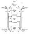
- FIG. 2shows a block diagram of an optical cross-connect system 200 configured with a conventional triplicated switch fabric to provide fault tolerance for error-less switching.
- optical cross-connect system 200comprises three optical cross-connect switch fabrics 202 , each configured to a controller 204 , 1024 STS-48 input interfaces 206 , and 1024 STS-48 output interfaces 208 .
- the input signal from each input interface 206is transmitted to each of the three switch fabrics 202 via three different input fibers 210 and each output interface 208 receives an output signal from each of the three switch fabrics 202 via a different output fiber 212 .
- each output interface 208implements a fault-detection and error-recovery scheme to produce an appropriate output signal.
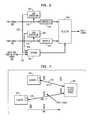
- FIG. 3shows a block diagram of the components used to implement the fault-detection and error-recovery scheme within each output interface 208 of FIG. 2 .
- each output signalis routed via output optical fiber 212 through a buffer 301 to a selector 303 .
- there are three independent monitors 305each of which monitors the corresponding output signal for failure (e.g., a signal open or a signal short).
- a voter 307monitors the status of the signals and causes selector 303 to select a healthy signal from the three incoming signals as the output signal for the corresponding output interface 208 .
- the health of a signalis determined by majority voting. In the event of failure in one signal, information from two healthy signals will match and voter 307 will cause selector 303 to select one of the healthy signals for transmission.
- the present inventionis directed to fault-tolerance techniques having lower overhead than traditional techniques which require triplicated switch fabrics, triplicated fiber cables, and triplicated buffering to achieve error-less switching.
- the present inventionemploys only a duplicated switch fabric and a small amount of storage to ensure error-less transmission in the event of equipment failure or a fiber cut.
- a small electronic byte slice switchis used to transport check bytes for facilitating fast fault detection with a relatively small amount of storage required. As such, the present invention can provide large savings in equipment cost.
- the present inventionis a cross-connect system, comprising (a) two information switch fabrics; (b) a plurality of input interfaces, each of which is coupled to transmit an input information signal to each of the two information switch fabrics; (c) a plurality of output interfaces, each of which is coupled to receive an output information signal from each of the two information switch fabrics; and (d) a code switch fabric, coupled to receive an input check-code signal from each input interface corresponding to the corresponding input information signal and to transmit an output check-code signal to the corresponding output interface.
- Each output interfacegenerates a local check-code signal for an output information signal and compares the local check-code signal to the output check-code signal to select one of the two output information signals as an output signal for the output interface.
- the present invenitionis a method for switching signals in a cross-connect system, comprising the steps of (a) generating an input check-code signal for each input information signal; (b) routing each input information signal through two information switch fabrics to generate two output information signals for the input information signal; (c) routing the input check-code signal through a code switch fabric to generate an output check-code signal; (d) generating a local check-code signal for an output information signal; and (e) comparing the output check-code signal to the local check-code signal to select one of the two output information signals as an output signal corresponding to the input information signal.
- FIG. 1shows a high-level block diagram of an optical cross-connect system
- FIG. 2shows a block diagram of an optical cross-connect system configured with a conventional triplicated switch fabric to provide fault tolerance for error-less switching;
- FIG. 3shows a block diagram of the components used to implement the fault-detection and error-recovery scheme in each output interface of FIG. 2 ;
- FIG. 4shows a block diagram of an optical cross-connect system, according to one embodiment of the present invention.
- FIG. 5shows a block diagram illustrating the clustering scheme for the optical cross-connect system of FIG. 4 ;
- FIG. 6shows a block diagram of the components used to implement the fault-detection and error-recovery scheme in each output interface cluster of FIG. 5 ;
- FIG. 7shows a block diagram illustrating the delay management technique for the system of FIGS. 4 - 6 .
- FIG. 4shows a block diagram of an optical cross-connect system 400 , according to one embodiment of the present invention.
- Optical cross-connect system 400comprises two optical cross-connect information switch fabrics 402 , each configured to a controller 404 , 1024 STS-48 input interfaces 406 , and 1024 STS-48 output interfaces 408 , where the input information signal from each input interface 406 is transmitted to each of the two information switch fabrics 402 via two different input optical fibers 410 and each output interface 408 receives an output information signal from each of the two information switch fabrics 402 via a different output optical fiber 412 .
- Each information switch fabric 402 in optical cross-connect system 400routes optical information signals in a manner analogous to that implemented by each switch fabric 202 of optical cross-connect system 200 of FIG. 2 .
- optical cross-connect system 400implements a code-based fault-detection and error-recovery scheme to achieve error-less switching in the event of a switch failure or a fiber cut.
- optical cross-connect system 400further comprises a code switch fabric 414 , configured to controller 404 and further configured to receive an input check-code signal 416 from each input interface 406 and to transmit an output check-code signal 418 to each output interface 408 .
- code switch fabric 414is an electronic switch fabric, although, in alternative embodiments, code switch fabric 414 may be an optical switch fabric, similar to the two optical cross-connect information switch fabrics 402 .
- each input interface 406generates an input check-code signal 416 based on its corresponding input information signal.
- the present inventioncan be implemented using any one of a variety of different suitable coding techniques, such as parity codes, checksum codes, CRC (cyclic redundancy check) codes, Reed-Solomon codes, or BCH (Bose Chaudhary) codes, to name a few.
- a check-code wordis generated for every 12 information data words.
- the different input check-code signals 416are multiplexed and transported through code switch fabric 414 , which then transmits the corresponding output check-code signals 418 to the appropriate output interfaces 408 .
- the input and output interfaces 406 and 408are clustered to enable efficient multiplexing of the various input and output check-code signals.
- FIG. 5shows a block diagram illustrating the clustering scheme for optical cross-connect system 400 , according to one embodiment of the present invention.
- the 1024 input interfaces 406 of FIG. 4are clustered into 64 input interface clusters 520 , each having a different set of 16 input interfaces 406 .
- the 1024 output interfaces 408are clustered into 64 output interface clusters 522 , each having a different set of 16 input interfaces 408 .
- the 16 different input check-code signals 416 from each input interface cluster 520are multiplexed together into a multiplexed input check-code signal that is transmitted over a single input cable 524 to electronic code switch fabric 414 .
- code switch fabric 414transmits a multiplexed output check-code signal over a single output cable 526 to each output interface cluster 522 , where each multiplexed output check-code signal comprises the 16 corresponding output check-code signals 418 multiplexed together.
- optical cross-connect system 400requires only 64 input cables and only 64 output cables to and from code switch fabric 414 to support all 1024 input check-code signals and all 1024 output check-code signals, respectively.
- code switch fabric 414demultiplexes all of the check bytes in each multiplexed input check-code signal and rearranges the bytes for the 16 STS-48 check-code signals targeted for the same output interface cluster 522 onto one STS-48 check-code signal for routing through code switch fabric 414 .
- FIG. 6shows a block diagram of the components used to implement the fault-detection and error-recovery scheme within each output interface cluster 522 of FIG. 5 , according to one embodiment of the present invention.
- each corresponding output information signal from the two information switch fabrics 402is routed via corresponding output optical fiber 412 through a buffer 601 to a selector 603 .
- there are two independent code-generation modules 605which perform the same code-generation processing on the corresponding output information signal that was performed on the corresponding input information signal in the corresponding input interface 406 of FIG. 4 .
- the resulting local check-code signals 609are transmitted, along with the corresponding output check-code signal 418 received from code switch fabric 414 , to a compare module 607 , which compares the check codes in output check-code signal 418 with the two local check-code signals 609 to determine if either of them is in error.
- the fiber cable lengths between each interface cluster and the switch fabricare made substantially equal.
- Another approachis to employ position-dependent sync management.
- the first approachmay require a relatively large amount of cable storage.
- the second approachis preferred due to the elimination of storage for fiber slack.
- a test frameis sent to the switch fabric and looped back.
- the distanceis then calculated based on the round-trip delay.
- the corresponding frame sync pulseis appropriately delayed. For example, assume that Cluster 1 has a 500-ft cable distance from the optical information switch fabric 402 and Cluster m has a 1000-ft cable distance. Since Cluster 1 is closer to the switch fabric, its frame sync pulse is appropriately delayed compared to that of Cluster m to ensure that the corresponding output data are aligned when they arrive at the output buffers 601
- each STS-48 input signalis demultiplexed into four TXI signals (each having a bit rate of 622 Mb/s).
- Table Ishows the byte order for the four TXI signals relative to each STS-48 signal.
- Table IIshows the alignment of the check codes. Note that C1 is calculated over the first 16 bytes, C2 is calculated over the next 16 bytes, and C3 is calculated over the remaining 16 bytes.
- TXI-11 4 7 10 2 5 8 11 3 6 9 12 TXI-2 13 16 19 22 14 17 20 23 15 18 21 24 TXI-3 25 28 31 34 26 29 32 35 27 30 33 36 TXI-4 37 40 43 46 38 41 44 47 39 42 45 48
- the order of bytes in sets of signalsis rearranged by shuffle blocks prior to routing through the switch fabrics.
- the original order of bytesis then restored by un-shuffle blocks after the shuffled signals are routed through the switch fabrics.
- shuffle blocks (S.B.) 528are implemented in input interface clusters 520 as well as at the input of code switch fabric 414
- un-shuffle blocks (U.B.) 530are implemented in output interface clusters 522 as well as at the output of code switch fabric 414 .
- Table IIIshows the alignment of check bytes before a shuffle block for four different STS-48 signals.
- Each shuffle blocktakes as an input four code TXI from four different STS-48 signals and creates one TXI as shown in Table IV.
- a first shuffle blocktakes as an input [1-]-TXI-C signals shown in Table III and generates a G1-TXI-C signal as shown in Table 4.
- three other shuffle blocksgenerate corresponding TXI signals for the remaining 12 STS-48 signals as [G2-G4]-TXI-C. These four TXIs are then multiplexed to generate one STS-48 check-code signal.
- Table Vshows the overhead involved in the prior-art fault-tolerance scheme of FIGS. 2-3 as compared with the overhead involved in the fault-tolerance scheme of FIGS. 4-6 of the present invention, for three different types of optical cross-connect (XCON) systems (i.e., having different numbers of input and output interfaces).
- XCONoptical cross-connect
- the present inventionprovides significant overhead savings in terms of number of fibers and power dissipation with only a slight increase in buffer storage requirements. Power dissipation values in Table V are estimated based on currently available system data.
- the low-overhead fault-tolerance technique of the present inventionis very effective in offering error-less transmission for optical cross-connect systems with significant reduction in number of cables as well as total system power dissipation. As the capacity of systems increase, the fault-tolerance overhead savings increase even more with the present invention.
- FIG. 6shows two code generation modules 605 generating two local check-code signals 609 , one for each output information signal stored in a different buffer 601 , those skilled in the art will understand that the present invention could be implemented with a single code generation module that generates only one local check-code signal (e.g., for the currently selected “working” signal) and that, if a failure is detected in that one local check-code signal, then protection switching will occur to select the other “protection” signal as the output signal.
- Such an embodimentmight not be preferred (e.g., unnecessary, but harmless protection switching will occur in the event of a failure in the code-check signal path), but it is nevertheless feasible and may even provide even lower fault-tolerance overhead.
- the present inventionhas been described in the context of a system that provides error-less switching, other applications, such as switching of voice signals, may require only hitless switching (in which some errors can be tolerated). For those applications, the present invention can be implemented with less, or even no, buffering, depending on the system requirements.
- electronic code switch fabric 414 of system 400can itself be duplicated to further increase the reliability of the fault-detection scheme of the present invention without much increase in fault-tolerance overhead.
- the present inventionmay be implemented as circuit-based processes, including possible implementation on a single integrated circuit.
- various functions of circuit elementsmay also be implemented as processing steps in a software program.
- Such softwaremay be employed in, for example, a digital signal processor, micro-controller, or general-purpose computer.
Landscapes
- Engineering & Computer Science (AREA)
- Computer Networks & Wireless Communication (AREA)
- Signal Processing (AREA)
- Use Of Switch Circuits For Exchanges And Methods Of Control Of Multiplex Exchanges (AREA)
Abstract
Description
| TABLE I |
| Byte order on incoming TXI signals |
| TXI-1 | 1 | 4 | 7 | 10 | 2 | 5 | 8 | 11 | 3 | 6 | 9 | 12 |
| TXI-2 | 13 | 16 | 19 | 22 | 14 | 17 | 20 | 23 | 15 | 18 | 21 | 24 |
| TXI-3 | 25 | 28 | 31 | 34 | 26 | 29 | 32 | 35 | 27 | 30 | 33 | 36 |
| TXI-4 | 37 | 40 | 43 | 46 | 38 | 41 | 44 | 47 | 39 | 42 | 45 | 48 |
| TABLE II |
| Byte order for check codes |
| TXI-1 | 1 | 4 | 7 | 10 | 2 | 5 | 8 | 11 | 3 | 6 | 9 | 12 |
| TXI-2 | 13 | 16 | 19 | 22 | 14 | 17 | 20 | 23 | 15 | 18 | 21 | 24 |
| TXI-3 | 25 | 28 | 31 | 34 | 26 | 29 | 32 | 35 | 27 | 30 | 33 | 36 |
| TXI-4 | 37 | 40 | 43 | 46 | 38 | 41 | 44 | 47 | 39 | 42 | 45 | 48 |
| TXI-C | C1 | C2 | C3 | |||||||||
| TABLE III |
| Byte order for check bytes |
| 1-TXI- | 1, | 1, | 1, C3 | ||
| 2-TXI- | 2, | 2, | 2, C3 | ||
| 3-TXI- | 3, | 3, | 3, C3 | ||
| 4-TXI-C | 4, C1 | 4, C2 | 4, C3 | ||
| TABLE IV |
| Byte order for check bytes |
| G1-TXI- | 1, | 2, | 3, C1 | 4, | 1, | 2, | 3, C2 | 4, | 1, | 2, | 3, C3 | 4, C3 |
| G2-TXI-C | 5, C1 | 6, C1 | 7, C1 | 8, C1 | 5, C2 | 6, C2 | 7, C2 | 8, C2 | 5, C3 | 6, C3 | 7, C3 | 8, C3 |
| G3-TXI-C | 9, C1 | 10, C1 | 11, C1 | 12, C1 | 9, C2 | 10, C2 | 11, C2 | 12, C2 | 9, C3 | 10, C3 | 11, C3 | 12, C3 |
| G4-TXI-C | 13, C1 | 14, C1 | 15, | 16, C1 | 13, C2 | 14, C2 | 15, | 16, C2 | 13, C3 | 14, C3 | 15, | 16, C3 |
Fault-Tolerance Overhead Savings
| TABLE V |
| Comparison of Prior Art and Invention |
| Prior Art | Invention |
| Number | Buffer | Power | Number | Buffer | Power | |
| of | Storage | Dissipation | of | Storage | Dissipation | |
| Type of System | Fibers | (Bytes) | (Watts) | Fibers | (Bytes) | (Watts) |
| 256 × 256 STS-48 XCON | 1536 | 4 | 3000 | 1056 | 16 | 2100 |
| 512 × 512 STS-48 XCON | 3072 | 4 | 6000 | 2112 | 16 | 4200 |
| 1024 × 1024 STS-48 XCON | 6144 | 4 | 12000 | 4224 | 16 | 8400 |
Claims (15)
Priority Applications (1)
| Application Number | Priority Date | Filing Date | Title |
|---|---|---|---|
| US09/614,436US6850704B1 (en) | 1999-09-14 | 2000-07-12 | Low-overhead fault-tolerance techniques for optical and other cross-connect systems |
Applications Claiming Priority (2)
| Application Number | Priority Date | Filing Date | Title |
|---|---|---|---|
| US15388099P | 1999-09-14 | 1999-09-14 | |
| US09/614,436US6850704B1 (en) | 1999-09-14 | 2000-07-12 | Low-overhead fault-tolerance techniques for optical and other cross-connect systems |
Publications (1)
| Publication Number | Publication Date |
|---|---|
| US6850704B1true US6850704B1 (en) | 2005-02-01 |
Family
ID=34082617
Family Applications (1)
| Application Number | Title | Priority Date | Filing Date |
|---|---|---|---|
| US09/614,436Expired - LifetimeUS6850704B1 (en) | 1999-09-14 | 2000-07-12 | Low-overhead fault-tolerance techniques for optical and other cross-connect systems |
Country Status (1)
| Country | Link |
|---|---|
| US (1) | US6850704B1 (en) |
Cited By (24)
| Publication number | Priority date | Publication date | Assignee | Title |
|---|---|---|---|---|
| US20010024305A1 (en)* | 2000-03-21 | 2001-09-27 | Hiroshi Nishimoto | Optical node device and signal switching and connection method |
| US20030058791A1 (en)* | 2001-09-27 | 2003-03-27 | Joseph Soetemans | Method and apparatus for optimization of redundant link usage in a multi-shelf network element |
| US20030058618A1 (en)* | 2001-09-27 | 2003-03-27 | Joseph Soetemans | Method and apparatus for providing a common support services infrastructure for a network element |
| US20030119555A1 (en)* | 2001-09-27 | 2003-06-26 | Larry Friesen | System for providing fabric activity switch control in a communications system |
| US20030123876A1 (en)* | 2000-01-28 | 2003-07-03 | Erland Almstrom | Cross -connect protection |
| US20030226091A1 (en)* | 2002-05-31 | 2003-12-04 | Scott Platenberg | Redundant path communication methods and systems |
| US20030227945A1 (en)* | 2002-06-10 | 2003-12-11 | Velio Communications, Inc. | Method and apparatus for ensuring cell ordering in large capacity switching systems and for synchronizing the arrival time of cells to a switch fabric |
| US20040003158A1 (en)* | 2002-06-28 | 2004-01-01 | Doblar Drew G. | Centerplaneless computer system |
| US20050083921A1 (en)* | 2000-10-31 | 2005-04-21 | Chiaro Networks Ltd. | Router switch fabric protection using forward error correction |
| US20060080430A1 (en)* | 2004-10-07 | 2006-04-13 | International Business Machines Corporation | System, method and program to identify failed components in storage area network |
| US20100061242A1 (en)* | 2008-09-11 | 2010-03-11 | Pradeep Sindhu | Methods and apparatus related to a flexible data center security architecture |
| US20100061240A1 (en)* | 2008-09-11 | 2010-03-11 | Pradeep Sindhu | Methods and apparatus related to low latency within a data center |
| US20100061241A1 (en)* | 2008-09-11 | 2010-03-11 | Pradeep Sindhu | Methods and apparatus related to flow control within a data center switch fabric |
| US20100061389A1 (en)* | 2008-09-11 | 2010-03-11 | Pradeep Sindhu | Methods and apparatus related to virtualization of data center resources |
| US20100061391A1 (en)* | 2008-09-11 | 2010-03-11 | Pradeep Sindhu | Methods and apparatus related to a low cost data center architecture |
| US20100061394A1 (en)* | 2008-09-11 | 2010-03-11 | Pradeep Sindhu | Methods and apparatus related to any-to-any connectivity within a data center |
| US20100061367A1 (en)* | 2008-09-11 | 2010-03-11 | Pradeep Sindhu | Methods and apparatus related to lossless operation within a data center |
| US20100329249A1 (en)* | 2009-06-30 | 2010-12-30 | Sathish Shenoy | Methods and apparatus for dynamic detection of transit times between stages in distributed multi-stage switch fabrics |
| US7920920B1 (en)* | 2006-08-31 | 2011-04-05 | Pacesetter, Inc. | Algorithm for capture detection |
| US20110238816A1 (en)* | 2010-03-23 | 2011-09-29 | Juniper Networks, Inc. | Methods and apparatus for automatically provisioning resources within a distributed control plane of a switch |
| US9282060B2 (en) | 2010-12-15 | 2016-03-08 | Juniper Networks, Inc. | Methods and apparatus for dynamic resource management within a distributed control plane of a switch |
| US20160173964A1 (en)* | 2014-12-11 | 2016-06-16 | Alcatel-Lucent Usa Inc. | Hybrid optical switch for software-defined networking |
| US9813252B2 (en) | 2010-03-23 | 2017-11-07 | Juniper Networks, Inc. | Multicasting within a distributed control plane of a switch |
| US11271871B2 (en) | 2008-09-11 | 2022-03-08 | Juniper Networks, Inc. | Methods and apparatus related to a flexible data center security architecture |
Citations (9)
| Publication number | Priority date | Publication date | Assignee | Title |
|---|---|---|---|---|
| US4535442A (en)* | 1982-04-24 | 1985-08-13 | The Plessey Company Plc | Digital switching network for telecommunications exchange |
| US4706240A (en)* | 1985-11-29 | 1987-11-10 | American Telephone And Telegraph Co., At&T Bell Labs | Switching system having multiple parallel switching networks |
| US5107361A (en)* | 1989-10-24 | 1992-04-21 | Alcatel N.V. | Optical subscriber network |
| US5130974A (en)* | 1989-03-30 | 1992-07-14 | Nec Corporation | Multidrop control network commonly used for carrying network management signals and topology reconfiguration signals |
| US5450397A (en)* | 1993-02-15 | 1995-09-12 | Telefonaktiebolaget Lm Ericsson | Method for handling redundant switching planes in packet switches and a packet switch for carrying out the method |
| US5485453A (en)* | 1993-02-15 | 1996-01-16 | Telefonaktiebolaget L M Ericsson | Method for handling redundant switching planes in packet switches and a packet switch for carrying out the method |
| US6072610A (en)* | 1996-04-15 | 2000-06-06 | Fujitsu Limited | Optical transmission system |
| US6362905B1 (en)* | 1997-02-24 | 2002-03-26 | Hitachi, Ltd. | Optical crossconnect apparatus and optical transmission system |
| US6433900B1 (en)* | 1998-02-20 | 2002-08-13 | Fujitsu Limited | Optical wavelength multiplexing system having a redundant configuration |
- 2000
- 2000-07-12USUS09/614,436patent/US6850704B1/ennot_activeExpired - Lifetime
Patent Citations (9)
| Publication number | Priority date | Publication date | Assignee | Title |
|---|---|---|---|---|
| US4535442A (en)* | 1982-04-24 | 1985-08-13 | The Plessey Company Plc | Digital switching network for telecommunications exchange |
| US4706240A (en)* | 1985-11-29 | 1987-11-10 | American Telephone And Telegraph Co., At&T Bell Labs | Switching system having multiple parallel switching networks |
| US5130974A (en)* | 1989-03-30 | 1992-07-14 | Nec Corporation | Multidrop control network commonly used for carrying network management signals and topology reconfiguration signals |
| US5107361A (en)* | 1989-10-24 | 1992-04-21 | Alcatel N.V. | Optical subscriber network |
| US5450397A (en)* | 1993-02-15 | 1995-09-12 | Telefonaktiebolaget Lm Ericsson | Method for handling redundant switching planes in packet switches and a packet switch for carrying out the method |
| US5485453A (en)* | 1993-02-15 | 1996-01-16 | Telefonaktiebolaget L M Ericsson | Method for handling redundant switching planes in packet switches and a packet switch for carrying out the method |
| US6072610A (en)* | 1996-04-15 | 2000-06-06 | Fujitsu Limited | Optical transmission system |
| US6362905B1 (en)* | 1997-02-24 | 2002-03-26 | Hitachi, Ltd. | Optical crossconnect apparatus and optical transmission system |
| US6433900B1 (en)* | 1998-02-20 | 2002-08-13 | Fujitsu Limited | Optical wavelength multiplexing system having a redundant configuration |
Non-Patent Citations (2)
| Title |
|---|
| Thuppal, R. and R. Venkatesan. "Design and implementation of control plane and data plane ASICs for pipelined banyan network." IEEE Canadian Conference on Electrical and Computer Engineering, 1998. May 24-28, 1998: 241-244 vol. 1.** |
| Venkatesan, R. et al. "Pipelined balanced gamma network for broadband communications switch fabrics." IEEE 1997 Canadian Conference on Electrical and Computer Engineering, 1997, May 25-28, 1997: 680-683 vol. 2.* |
Cited By (52)
| Publication number | Priority date | Publication date | Assignee | Title |
|---|---|---|---|---|
| US20030123876A1 (en)* | 2000-01-28 | 2003-07-03 | Erland Almstrom | Cross -connect protection |
| US20010024305A1 (en)* | 2000-03-21 | 2001-09-27 | Hiroshi Nishimoto | Optical node device and signal switching and connection method |
| US8315175B2 (en)* | 2000-10-31 | 2012-11-20 | Foundry Networks, Llc | Router switch fabric protection using forward error correction |
| US20050083921A1 (en)* | 2000-10-31 | 2005-04-21 | Chiaro Networks Ltd. | Router switch fabric protection using forward error correction |
| US7099271B2 (en)* | 2001-09-27 | 2006-08-29 | Alcatel Canada Inc. | System for providing fabric activity switch control in a communications system |
| US20030058791A1 (en)* | 2001-09-27 | 2003-03-27 | Joseph Soetemans | Method and apparatus for optimization of redundant link usage in a multi-shelf network element |
| US20030058618A1 (en)* | 2001-09-27 | 2003-03-27 | Joseph Soetemans | Method and apparatus for providing a common support services infrastructure for a network element |
| US20030119555A1 (en)* | 2001-09-27 | 2003-06-26 | Larry Friesen | System for providing fabric activity switch control in a communications system |
| US7710866B2 (en)* | 2001-09-27 | 2010-05-04 | Alcatel-Lucent Canada Inc. | Method and apparatus for optimization of redundant link usage in a multi-shelf network element |
| US7619886B2 (en) | 2001-09-27 | 2009-11-17 | Alcatel-Lucent Canada Inc. | Method and apparatus for providing a common support services infrastructure for a network element |
| US20030226091A1 (en)* | 2002-05-31 | 2003-12-04 | Scott Platenberg | Redundant path communication methods and systems |
| US7127669B2 (en)* | 2002-05-31 | 2006-10-24 | Kiribati Wireless Ventures, Llc | Redundant path communication methods and systems |
| US20070011587A1 (en)* | 2002-05-31 | 2007-01-11 | Kiribati Wireless Ventures, Llc | Redundant path communication methods and systems |
| US7770097B2 (en) | 2002-05-31 | 2010-08-03 | Scott Platenberg | Redundant path communication methods and systems |
| US7408959B2 (en)* | 2002-06-10 | 2008-08-05 | Lsi Corporation | Method and apparatus for ensuring cell ordering in large capacity switching systems and for synchronizing the arrival time of cells to a switch fabric |
| US20030227945A1 (en)* | 2002-06-10 | 2003-12-11 | Velio Communications, Inc. | Method and apparatus for ensuring cell ordering in large capacity switching systems and for synchronizing the arrival time of cells to a switch fabric |
| US7296106B2 (en)* | 2002-06-28 | 2007-11-13 | Sun Microsystems, Inc. | Centerplaneless computer system |
| US20040003158A1 (en)* | 2002-06-28 | 2004-01-01 | Doblar Drew G. | Centerplaneless computer system |
| US7457871B2 (en)* | 2004-10-07 | 2008-11-25 | International Business Machines Corporation | System, method and program to identify failed components in storage area network |
| US20060080430A1 (en)* | 2004-10-07 | 2006-04-13 | International Business Machines Corporation | System, method and program to identify failed components in storage area network |
| US7920920B1 (en)* | 2006-08-31 | 2011-04-05 | Pacesetter, Inc. | Algorithm for capture detection |
| US8958432B2 (en) | 2008-09-11 | 2015-02-17 | Juniper Networks, Inc. | Methods and apparatus related to a flexible data center security architecture |
| US8335213B2 (en) | 2008-09-11 | 2012-12-18 | Juniper Networks, Inc. | Methods and apparatus related to low latency within a data center |
| US20100061367A1 (en)* | 2008-09-11 | 2010-03-11 | Pradeep Sindhu | Methods and apparatus related to lossless operation within a data center |
| US20100061389A1 (en)* | 2008-09-11 | 2010-03-11 | Pradeep Sindhu | Methods and apparatus related to virtualization of data center resources |
| US20100061241A1 (en)* | 2008-09-11 | 2010-03-11 | Pradeep Sindhu | Methods and apparatus related to flow control within a data center switch fabric |
| US9985911B2 (en) | 2008-09-11 | 2018-05-29 | Juniper Networks, Inc. | Methods and apparatus related to a flexible data center security architecture |
| US20100061240A1 (en)* | 2008-09-11 | 2010-03-11 | Pradeep Sindhu | Methods and apparatus related to low latency within a data center |
| US20100061391A1 (en)* | 2008-09-11 | 2010-03-11 | Pradeep Sindhu | Methods and apparatus related to a low cost data center architecture |
| US8265071B2 (en) | 2008-09-11 | 2012-09-11 | Juniper Networks, Inc. | Methods and apparatus related to a flexible data center security architecture |
| US8340088B2 (en) | 2008-09-11 | 2012-12-25 | Juniper Networks, Inc. | Methods and apparatus related to a low cost data center architecture |
| US20100061394A1 (en)* | 2008-09-11 | 2010-03-11 | Pradeep Sindhu | Methods and apparatus related to any-to-any connectivity within a data center |
| US20100061242A1 (en)* | 2008-09-11 | 2010-03-11 | Pradeep Sindhu | Methods and apparatus related to a flexible data center security architecture |
| US10454849B2 (en) | 2008-09-11 | 2019-10-22 | Juniper Networks, Inc. | Methods and apparatus related to a flexible data center security architecture |
| US8730954B2 (en) | 2008-09-11 | 2014-05-20 | Juniper Networks, Inc. | Methods and apparatus related to any-to-any connectivity within a data center |
| US8755396B2 (en) | 2008-09-11 | 2014-06-17 | Juniper Networks, Inc. | Methods and apparatus related to flow control within a data center switch fabric |
| US9847953B2 (en) | 2008-09-11 | 2017-12-19 | Juniper Networks, Inc. | Methods and apparatus related to virtualization of data center resources |
| US12068978B2 (en) | 2008-09-11 | 2024-08-20 | Juniper Networks, Inc. | Methods and apparatus related to a flexible data center security architecture |
| US11451491B2 (en) | 2008-09-11 | 2022-09-20 | Juniper Networks, Inc. | Methods and apparatus related to virtualization of data center resources |
| US11271871B2 (en) | 2008-09-11 | 2022-03-08 | Juniper Networks, Inc. | Methods and apparatus related to a flexible data center security architecture |
| US10536400B2 (en) | 2008-09-11 | 2020-01-14 | Juniper Networks, Inc. | Methods and apparatus related to virtualization of data center resources |
| US8279863B2 (en) | 2009-06-30 | 2012-10-02 | Juniper Networks, Inc. | Methods and apparatus for dynamic detection of transit times between stages in distributed multi-stage switch fabrics |
| US20100329249A1 (en)* | 2009-06-30 | 2010-12-30 | Sathish Shenoy | Methods and apparatus for dynamic detection of transit times between stages in distributed multi-stage switch fabrics |
| US20110238816A1 (en)* | 2010-03-23 | 2011-09-29 | Juniper Networks, Inc. | Methods and apparatus for automatically provisioning resources within a distributed control plane of a switch |
| US9813252B2 (en) | 2010-03-23 | 2017-11-07 | Juniper Networks, Inc. | Multicasting within a distributed control plane of a switch |
| US10645028B2 (en) | 2010-03-23 | 2020-05-05 | Juniper Networks, Inc. | Methods and apparatus for automatically provisioning resources within a distributed control plane of a switch |
| US10887119B2 (en) | 2010-03-23 | 2021-01-05 | Juniper Networks, Inc. | Multicasting within distributed control plane of a switch |
| US9240923B2 (en) | 2010-03-23 | 2016-01-19 | Juniper Networks, Inc. | Methods and apparatus for automatically provisioning resources within a distributed control plane of a switch |
| US9674036B2 (en) | 2010-12-15 | 2017-06-06 | Juniper Networks, Inc. | Methods and apparatus for dynamic resource management within a distributed control plane of a switch |
| US9282060B2 (en) | 2010-12-15 | 2016-03-08 | Juniper Networks, Inc. | Methods and apparatus for dynamic resource management within a distributed control plane of a switch |
| US9712899B2 (en)* | 2014-12-11 | 2017-07-18 | Alcatel Lucent | Hybrid optical switch for software-defined networking |
| US20160173964A1 (en)* | 2014-12-11 | 2016-06-16 | Alcatel-Lucent Usa Inc. | Hybrid optical switch for software-defined networking |
Similar Documents
| Publication | Publication Date | Title |
|---|---|---|
| US6850704B1 (en) | Low-overhead fault-tolerance techniques for optical and other cross-connect systems | |
| Ayanoglu et al. | Diversity coding for transparent self-healing and fault-tolerant communication networks | |
| EP0548648B1 (en) | 1:N Ring-type signal protection apparatus | |
| US6587235B1 (en) | Method and apparatus for capacity-efficient restoration in an optical communication system | |
| US6879559B1 (en) | Router line card protection using one-for-N redundancy | |
| US5729527A (en) | Fault management in a multichannel transmission system | |
| US5333130A (en) | Self-healing drop and insert communication network | |
| US7324500B1 (en) | Router network protection using multiple facility interfaces | |
| JP3740969B2 (en) | Optical cross-connect device | |
| US20120251097A1 (en) | Passive architectural optical distribution network | |
| CN1848709A (en) | Passive optical network system and protection switching method for realizing protection switching | |
| US5978120A (en) | Optical switch arrangement with synchronisation feature and in particular optical protection switching module and optical hitless protection switching module using such an arrangement and methods realized by such arrangement and modules | |
| US5007067A (en) | Diversity coding for transparent self-healing communications networks | |
| US6914879B1 (en) | Network element with redundant switching matrix | |
| US8018838B2 (en) | Apparatus and method for protection switching in a network | |
| US8149687B2 (en) | Intra-node fault recovery within a multi-stage switching architecture | |
| US8861956B2 (en) | Apparatus and method for switching paths in a wavelength-multiplexing network | |
| US6831927B1 (en) | Fault protection for hitless and errorless switching of telecommunications signals | |
| US6870859B1 (en) | Multiplexing system and multiplexing method of tributary signals | |
| US7302190B2 (en) | Optical communication system including replaceable electro-optic and opto-electric converters | |
| EP1202599A2 (en) | System and method for routing IP packets using an optical core | |
| JP3123633B2 (en) | 1: n communication transmission method | |
| US6973041B1 (en) | Path AIS insertion for concatenated payloads across multiple processors | |
| US6950883B1 (en) | Ring capacity efficient architecture | |
| US20100138711A1 (en) | Equipment protection method and apparatus |
Legal Events
| Date | Code | Title | Description |
|---|---|---|---|
| AS | Assignment | Owner name:LUCENT TECHNOLOGIES INC., NEW JERSEY Free format text:ASSIGNMENT OF ASSIGNORS INTEREST;ASSIGNOR:DAVE, BHARAT P.;REEL/FRAME:010964/0385 Effective date:20000711 | |
| FEPP | Fee payment procedure | Free format text:PAYOR NUMBER ASSIGNED (ORIGINAL EVENT CODE: ASPN); ENTITY STATUS OF PATENT OWNER: LARGE ENTITY | |
| STCF | Information on status: patent grant | Free format text:PATENTED CASE | |
| FEPP | Fee payment procedure | Free format text:PAYOR NUMBER ASSIGNED (ORIGINAL EVENT CODE: ASPN); ENTITY STATUS OF PATENT OWNER: LARGE ENTITY Free format text:PAYER NUMBER DE-ASSIGNED (ORIGINAL EVENT CODE: RMPN); ENTITY STATUS OF PATENT OWNER: LARGE ENTITY | |
| FPAY | Fee payment | Year of fee payment:4 | |
| FPAY | Fee payment | Year of fee payment:8 | |
| FPAY | Fee payment | Year of fee payment:12 | |
| AS | Assignment | Owner name:OMEGA CREDIT OPPORTUNITIES MASTER FUND, LP, NEW YORK Free format text:SECURITY INTEREST;ASSIGNOR:WSOU INVESTMENTS, LLC;REEL/FRAME:043966/0574 Effective date:20170822 Owner name:OMEGA CREDIT OPPORTUNITIES MASTER FUND, LP, NEW YO Free format text:SECURITY INTEREST;ASSIGNOR:WSOU INVESTMENTS, LLC;REEL/FRAME:043966/0574 Effective date:20170822 | |
| AS | Assignment | Owner name:WSOU INVESTMENTS, LLC, CALIFORNIA Free format text:ASSIGNMENT OF ASSIGNORS INTEREST;ASSIGNOR:ALCATEL LUCENT;REEL/FRAME:044000/0053 Effective date:20170722 | |
| AS | Assignment | Owner name:BP FUNDING TRUST, SERIES SPL-VI, NEW YORK Free format text:SECURITY INTEREST;ASSIGNOR:WSOU INVESTMENTS, LLC;REEL/FRAME:049235/0068 Effective date:20190516 | |
| AS | Assignment | Owner name:WSOU INVESTMENTS, LLC, CALIFORNIA Free format text:RELEASE BY SECURED PARTY;ASSIGNOR:OCO OPPORTUNITIES MASTER FUND, L.P. (F/K/A OMEGA CREDIT OPPORTUNITIES MASTER FUND LP;REEL/FRAME:049246/0405 Effective date:20190516 | |
| AS | Assignment | Owner name:OT WSOU TERRIER HOLDINGS, LLC, CALIFORNIA Free format text:SECURITY INTEREST;ASSIGNOR:WSOU INVESTMENTS, LLC;REEL/FRAME:056990/0081 Effective date:20210528 | |
| AS | Assignment | Owner name:WSOU INVESTMENTS, LLC, CALIFORNIA Free format text:RELEASE BY SECURED PARTY;ASSIGNOR:TERRIER SSC, LLC;REEL/FRAME:056526/0093 Effective date:20210528 |