US6850557B1 - Signal detector and method employing a coherent accumulation system to correlate non-uniform and disjoint sample segments - Google Patents
Signal detector and method employing a coherent accumulation system to correlate non-uniform and disjoint sample segmentsDownload PDFInfo
- Publication number
- US6850557B1 US6850557B1US09/551,047US55104700AUS6850557B1US 6850557 B1US6850557 B1US 6850557B1US 55104700 AUS55104700 AUS 55104700AUS 6850557 B1US6850557 B1US 6850557B1
- Authority
- US
- United States
- Prior art keywords
- signal
- segment
- interest
- correlation
- correlation data
- Prior art date
- Legal status (The legal status is an assumption and is not a legal conclusion. Google has not performed a legal analysis and makes no representation as to the accuracy of the status listed.)
- Expired - Lifetime
Links
- 238000000034methodMethods0.000titleclaimsdescription95
- 230000001427coherent effectEffects0.000titleabstractdescription41
- 238000009825accumulationMethods0.000titleabstractdescription27
- 238000012545processingMethods0.000claimsabstractdescription41
- 238000004891communicationMethods0.000claimsdescription47
- 230000008569processEffects0.000claimsdescription43
- 230000001186cumulative effectEffects0.000claimsdescription32
- 238000005259measurementMethods0.000claimsdescription25
- 230000005540biological transmissionEffects0.000claimsdescription22
- 230000006870functionEffects0.000claimsdescription10
- 230000001413cellular effectEffects0.000claimsdescription5
- 230000004044responseEffects0.000claimsdescription2
- 230000010267cellular communicationEffects0.000claims4
- 238000004590computer programMethods0.000claims4
- 230000003213activating effectEffects0.000claims3
- 230000004913activationEffects0.000claims3
- 150000001768cationsChemical group0.000claims1
- 238000005314correlation functionMethods0.000claims1
- 230000009977dual effectEffects0.000claims1
- 238000010295mobile communicationMethods0.000claims1
- 238000005070samplingMethods0.000abstractdescription23
- 230000010354integrationEffects0.000abstractdescription14
- 238000013481data captureMethods0.000description49
- 230000000875corresponding effectEffects0.000description38
- 238000003491arrayMethods0.000description24
- 238000012937correctionMethods0.000description15
- 230000010363phase shiftEffects0.000description14
- 230000008859changeEffects0.000description9
- 238000012360testing methodMethods0.000description9
- 210000004027cellAnatomy0.000description8
- 239000013256coordination polymerSubstances0.000description8
- 238000001514detection methodMethods0.000description8
- 238000001228spectrumMethods0.000description7
- 230000008901benefitEffects0.000description6
- 230000007246mechanismEffects0.000description5
- 238000004364calculation methodMethods0.000description4
- 230000002596correlated effectEffects0.000description4
- 238000010219correlation analysisMethods0.000description4
- 238000010586diagramMethods0.000description4
- 230000000694effectsEffects0.000description4
- 230000003287optical effectEffects0.000description4
- 238000007726management methodMethods0.000description2
- 230000000737periodic effectEffects0.000description2
- 238000012805post-processingMethods0.000description2
- 238000007781pre-processingMethods0.000description2
- 230000035945sensitivityEffects0.000description2
- 238000012935AveragingMethods0.000description1
- 101100536250Homo sapiens TMEM120A geneProteins0.000description1
- 102100028548Ion channel TACANHuman genes0.000description1
- 239000004165Methyl ester of fatty acidsSubstances0.000description1
- 241000522620ScorpioSpecies0.000description1
- 238000013459approachMethods0.000description1
- 230000003416augmentationEffects0.000description1
- 238000010276constructionMethods0.000description1
- 125000004122cyclic groupChemical group0.000description1
- 238000013480data collectionMethods0.000description1
- 238000013500data storageMethods0.000description1
- 238000013461designMethods0.000description1
- 238000005516engineering processMethods0.000description1
- 238000005562fadingMethods0.000description1
- 238000001914filtrationMethods0.000description1
- PCHJSUWPFVWCPO-UHFFFAOYSA-NgoldChemical compound[Au]PCHJSUWPFVWCPO-UHFFFAOYSA-N0.000description1
- 239000010931goldSubstances0.000description1
- 229910052737goldInorganic materials0.000description1
- 239000000203mixtureSubstances0.000description1
- 239000013307optical fiberSubstances0.000description1
- 230000002093peripheral effectEffects0.000description1
- 230000009467reductionEffects0.000description1
- 239000009490scorpioSubstances0.000description1
- 239000004065semiconductorSubstances0.000description1
- 230000011664signalingEffects0.000description1
- 210000000352storage cellAnatomy0.000description1
- 230000001360synchronised effectEffects0.000description1
Images


Classifications
- G—PHYSICS
- G01—MEASURING; TESTING
- G01S—RADIO DIRECTION-FINDING; RADIO NAVIGATION; DETERMINING DISTANCE OR VELOCITY BY USE OF RADIO WAVES; LOCATING OR PRESENCE-DETECTING BY USE OF THE REFLECTION OR RERADIATION OF RADIO WAVES; ANALOGOUS ARRANGEMENTS USING OTHER WAVES
- G01S19/00—Satellite radio beacon positioning systems; Determining position, velocity or attitude using signals transmitted by such systems
- G01S19/01—Satellite radio beacon positioning systems transmitting time-stamped messages, e.g. GPS [Global Positioning System], GLONASS [Global Orbiting Navigation Satellite System] or GALILEO
- G01S19/13—Receivers
- G01S19/23—Testing, monitoring, correcting or calibrating of receiver elements
- G01S19/235—Calibration of receiver components
- G—PHYSICS
- G01—MEASURING; TESTING
- G01S—RADIO DIRECTION-FINDING; RADIO NAVIGATION; DETERMINING DISTANCE OR VELOCITY BY USE OF RADIO WAVES; LOCATING OR PRESENCE-DETECTING BY USE OF THE REFLECTION OR RERADIATION OF RADIO WAVES; ANALOGOUS ARRANGEMENTS USING OTHER WAVES
- G01S19/00—Satellite radio beacon positioning systems; Determining position, velocity or attitude using signals transmitted by such systems
- G01S19/01—Satellite radio beacon positioning systems transmitting time-stamped messages, e.g. GPS [Global Positioning System], GLONASS [Global Orbiting Navigation Satellite System] or GALILEO
- G01S19/13—Receivers
- G01S19/24—Acquisition or tracking or demodulation of signals transmitted by the system
- G01S19/29—Acquisition or tracking or demodulation of signals transmitted by the system carrier including Doppler, related
- G—PHYSICS
- G01—MEASURING; TESTING
- G01S—RADIO DIRECTION-FINDING; RADIO NAVIGATION; DETERMINING DISTANCE OR VELOCITY BY USE OF RADIO WAVES; LOCATING OR PRESENCE-DETECTING BY USE OF THE REFLECTION OR RERADIATION OF RADIO WAVES; ANALOGOUS ARRANGEMENTS USING OTHER WAVES
- G01S19/00—Satellite radio beacon positioning systems; Determining position, velocity or attitude using signals transmitted by such systems
- G01S19/01—Satellite radio beacon positioning systems transmitting time-stamped messages, e.g. GPS [Global Positioning System], GLONASS [Global Orbiting Navigation Satellite System] or GALILEO
- G01S19/13—Receivers
- G01S19/24—Acquisition or tracking or demodulation of signals transmitted by the system
- G01S19/30—Acquisition or tracking or demodulation of signals transmitted by the system code related
- H—ELECTRICITY
- H04—ELECTRIC COMMUNICATION TECHNIQUE
- H04B—TRANSMISSION
- H04B1/00—Details of transmission systems, not covered by a single one of groups H04B3/00 - H04B13/00; Details of transmission systems not characterised by the medium used for transmission
- H04B1/69—Spread spectrum techniques
- H04B1/707—Spread spectrum techniques using direct sequence modulation
- G—PHYSICS
- G01—MEASURING; TESTING
- G01S—RADIO DIRECTION-FINDING; RADIO NAVIGATION; DETERMINING DISTANCE OR VELOCITY BY USE OF RADIO WAVES; LOCATING OR PRESENCE-DETECTING BY USE OF THE REFLECTION OR RERADIATION OF RADIO WAVES; ANALOGOUS ARRANGEMENTS USING OTHER WAVES
- G01S19/00—Satellite radio beacon positioning systems; Determining position, velocity or attitude using signals transmitted by such systems
- G01S19/01—Satellite radio beacon positioning systems transmitting time-stamped messages, e.g. GPS [Global Positioning System], GLONASS [Global Orbiting Navigation Satellite System] or GALILEO
- G01S19/13—Receivers
- G01S19/24—Acquisition or tracking or demodulation of signals transmitted by the system
- G01S19/25—Acquisition or tracking or demodulation of signals transmitted by the system involving aiding data received from a cooperating element, e.g. assisted GPS
- G01S19/254—Acquisition or tracking or demodulation of signals transmitted by the system involving aiding data received from a cooperating element, e.g. assisted GPS relating to Doppler shift of satellite signals
- G—PHYSICS
- G01—MEASURING; TESTING
- G01S—RADIO DIRECTION-FINDING; RADIO NAVIGATION; DETERMINING DISTANCE OR VELOCITY BY USE OF RADIO WAVES; LOCATING OR PRESENCE-DETECTING BY USE OF THE REFLECTION OR RERADIATION OF RADIO WAVES; ANALOGOUS ARRANGEMENTS USING OTHER WAVES
- G01S19/00—Satellite radio beacon positioning systems; Determining position, velocity or attitude using signals transmitted by such systems
- G01S19/01—Satellite radio beacon positioning systems transmitting time-stamped messages, e.g. GPS [Global Positioning System], GLONASS [Global Orbiting Navigation Satellite System] or GALILEO
- G01S19/13—Receivers
- G01S19/24—Acquisition or tracking or demodulation of signals transmitted by the system
- G01S19/25—Acquisition or tracking or demodulation of signals transmitted by the system involving aiding data received from a cooperating element, e.g. assisted GPS
- G01S19/256—Acquisition or tracking or demodulation of signals transmitted by the system involving aiding data received from a cooperating element, e.g. assisted GPS relating to timing, e.g. time of week, code phase, timing offset
- H—ELECTRICITY
- H04—ELECTRIC COMMUNICATION TECHNIQUE
- H04L—TRANSMISSION OF DIGITAL INFORMATION, e.g. TELEGRAPHIC COMMUNICATION
- H04L27/00—Modulated-carrier systems
- H04L27/0014—Carrier regulation
- H04L2027/0024—Carrier regulation at the receiver end
- H04L2027/0026—Correction of carrier offset
- H04L2027/0034—Correction of carrier offset using hypothesis testing
Definitions
- This inventionrelates to the field of signal detection using correlation analysis, and more specifically, to correlation analysis in which the results of analyzing segments of samples separated in time and possibly having non-uniform lengths are coherently combined to achieve a greater effective signal-to-noise ratio (SNR).
- SNRsignal-to-noise ratio
- the NAVSTAR global positioning systemis a collection of 24 earth-orbiting satellites. Each of these GPS satellites travels in a precise orbit about 11,000 miles above the earth's surface. A GPS receiver locks onto at least 3 of the satellites, and responsive, thereto, is able to determine its precise location. Each satellite transmits a signal modulated with a unique pseudo-noise (PN) code. Each PN code comprises a sequence of 1023 chips that are repeated every millisecond consistent with a chip rate of 1.023 MHz. Each satellite transmits at the same frequency. For civil applications, the frequency is known as L1 and is 1575.42 MHz. The GPS receiver receives a signal that is a mixture of the transmissions of the satellites that are visible to the receiver.
- PNpseudo-noise
- the receiverdetects the transmission of a particular satellite by correlating the received signal with shifted versions of the PN code for that satellite. If the level of correlation is sufficiently high so that there is a peak in the level of correlation achieved for a particular shift and PN code, the receiver detects the transmission of the satellite corresponding to the particular PN code. The receiver then used the shifted PN code to achieve synchronization with subsequent transmissions from the satellite.
- the receiverdetermines its distance from the satellite by determining the code phase of the transmission from the satellite.
- the code phase(CP) is the delay, in terms of chips or fractions of chips, which a satellite transmission experiences as it travels the approximately 11,000 mile distance from the satellite to the receiver.
- the receiverdetermines the code phase for a particular satellite by correlating shifted versions of the satellite's PN code with the received signal after correction for Doppler shift.
- the code phase for the satelliteis determined to be the shift that maximizes the degree of correlation with the received signal.
- the receiverconverts the code phase for a satellite to a time delay. It determines the distance to the satellite by multiplying the time delay by the velocity of the transmission from the satellite. The receiver also knows the precise orbits of each of the satellites. The receiver uses this information to define a sphere around the satellite at which the receiver must be located, with the radius of the sphere equal to the distance the receiver has determined from the code phase. The receiver performs this process for at least three satellites. The receiver derives its precise location from the points of intersection between the at least three spheres it has defined.
- the Doppler shiftis a frequency shift in the satellite transmission caused by relative movement between the satellite and the receiver along the connection-of-sight (LOS). It can be shown that the frequency shift is equal to v LOS ⁇ , where v LOS is the velocity of the relative movement between the satellite and receiver along the LOS, and ⁇ is the wavelength of the transmission.
- the Doppler shiftis positive if the receiver and satellite are moving towards one another along the LOS, and is negative if the receiver and satellite are moving away from one another along the LOS.
- the Doppler shiftalters the perceived code phase of a satellite transmission from its actual value.
- the GPS receivermust correct the satellite transmissions for Doppler shift before it attempts to determine the code phase for the satellite through correlation analysis.
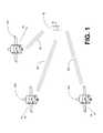
- FIG. 1shows a GPS receiver 10 and three GPS satellites 12 a , 12 b , and 12 c .
- Each satellite 12 a , 12 b , 12 cis transmitting to the GPS receiver 10 .
- Satellite 12 ais moving towards the GPS receiver 10 along the LOS at a velocity v a + 14;
- satellite 12 bis moving away from the GPS receiver 10 along the LOS at a velocity v c ⁇ 16;
- satellite 12 cis moving away from the GPS receiver 10 along the LOS at a velocity v c ⁇ 18.
- the transmission from satellite 12 awill experience a positive Doppler shift of v a + ⁇ ; the transmission from satellite 12 b will experience a negative Doppler shift of v b - ⁇ ; and the transmission from satellite 12 c will experience a negative Doppler shift of v c - ⁇ .
- the GPS receiver 10functions by sampling a finite portion of the received signal 20 and then processing the samples.
- external constraintslimit the size and occurrence of the sampling period.
- the sampling windowshould be limited to those periods in which the phone is not transmitting. The purpose is to avoid interference between the transmitter and the GPS receiver 10 .
- the signal-to-noise (S/N) ratio of the received signal 20 over a finite sampling windowmay not be sufficient to detect the presence and range of the satellites.
- the signalmay be such that there is no correlation value for a particular set of hypotheses which is significantly larger than the correlation values resulting from the other hypotheses tested.
- Such occurrencesare frequent because of the approximately 11,000 mile distance traveled by the GPS satellite transmissions, because of blockage, multipath fading or attenuation due to buildings, terrain or trees, and because of the noise to a particular satellite represented by the other satellite's transmissions.
- This inventionprovides a signal detector that employs a coherent accumulation system that coherently combines the correlation results derived from segments of samples of a received signal.
- the segmentsmay have non-uniform lengths and may have been obtained over different and non-overlapping time periods.
- the segmentsare obtained during sampling windows of arbitrary length and at arbitrary times, and the results of processing the segments are successively combined in a coherent manner (separate magnitude and phase accumulation) until a threshold signal-to-noise ratio (SNR) has been achieved.
- SNRthreshold signal-to-noise ratio
- coherent integrationis enabled by introducing a carrier Doppler phase offset as well as a code Doppler phase offset, so that different segments are aligned in phase.
- the coherent accumulation systemmay be implemented in a receiver configured to receive a first segment of a signal and a second segment of the signal that are acquired during different time periods.
- the received signalcomprises a signal of interest perturbed by noise or pseudo-noise.
- the signal detectorwhich includes the coherent accumulation system, includes a correlator and a combiner.
- the correlatorderives first correlation data representative of a first correlation between the first segment and a hypothesis.
- the correlatorimposes a carrier phase offset upon the second segment so that a carrier phase of the second segment corresponds to that of the first segment.
- the correlatorderives second correlation data representative of a second correlation between the phase shifted second segment and the hypothesis.
- a combinersuch as an integrator, coherently combines the first and second correlation data to obtain cumulative correlation data useful for detecting the signal of interest or a parameter of the signal of interest.
- the signal detectorcan be utilized in and as part of a GPS receiver, and it will be briefly described here in this context.
- the GPS receivermay comprise, for example, a radio frequency (RF) receiver, offset measurement circuitry, a PN code generator, the signal detector, a GPS processor.
- the RF receiverdemodulates the received signal to obtain a baseband signal.
- the PN code generatorgenerates the PN code hypotheses that are correlated with signal samples in the signal detector.
- the signal processorprocesses the segment of samples in accordance with a plurality of PN code, Doppler shift, and code phase hypotheses.
- the signal detectorFor each segment of samples, the signal detector outputs correlation data derived by correlating various combinations of PN code, Doppler shift, and code phase hypotheses with the segment of samples.
- the correlation datacan be grouped into groupings that correspond to various combinations of specific hypotheses and ranges of hypotheses.
- the correlation datacomprises a plurality of arrays, wherein each array corresponds to a PN code hypothesis, each row of an array corresponds to a Doppler shift hypothesis, each column of an array corresponds to a code phase hypothesis, and each entry in the array is a measure of the degree to which the combined PN code, Doppler shift, and code phase hypothesis corresponding to the entry correlates to the samples.
- the GPS processordirects the signal detector to process each segment of samples.
- the GPS processoralso, responsive to timing signals generated locally by the GPS radio receiver, generates frame marks which are input to the offset measurement circuitry.
- the offset measurement circuitrydetermines the offset between the time that a data capture command is issued by the GPS processor and the timing of the next frame mark. This information is provided to the GPS processor for use in determining a carrier phase offset and a code phase offset, so that the correlation results of processing different segments of samples can be coherently combined.
- Correlation datais coherently accumulated.
- the new correlation datais coherently combined with the cumulative correlation data.
- the GPS processoraccumulates the correlation data for a particular satellite until a threshold SNR is achieved.
- the data for a particular satelliteis maintained until the presence and range of the satellite can be determined.
- FIG. 1illustrates satellites transmitting spread spectrum modulated signals, for example, GPS signals, to a receiver.
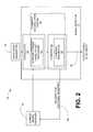
- FIG. 2illustrates an implementation example of a receiver having a signal detector that includes the coherent accumulation system of this invention for quickly and efficiently processing the signals of FIG. 1 .
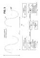
- FIG. 3illustrates the coherent accumulation system of FIG. 2 .
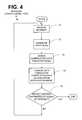
- FIG. 4illustrates an implementation example of a method of operation of the receiver of FIG. 1 .
- FIG. 5illustrates an implementation example of a GPS receiver that employs the signal detector having the coherent accumulation system of FIGS. 2 and 3 .
- FIG. 6illustrates a data format associated with GPS signals transmitted from the satellites of FIG. 1 .
- FIG. 7Aillustrates via a high level block diagram an implementation example of the signal detector of FIG. 5 .
- FIG. 7Billustrates via a low level block diagram the implementation example of the signal detector of FIG. 7 A.
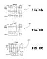
- FIG. 8illustrates examples of data structures output by the signal detector of FIG. 5 situated within the GPS receiver of FIG. 5 .
- FIG. 9illustrates an example of a timing diagram for illustrating the process of combining carrier and code phase shifts to enable coherent accumulation of data correlation values in the signal detector of FIG. 5 situated within the GPS receiver of FIG. 5 .
- FIGS. 10A-10Cillustrate an implementation example of a method of operation of the GPS receiver of FIG. 5 .
- FIG. 2A block diagram of a generalized embodiment (a nonlimiting implementation example) of a receiver 30 that employs a signal detector 32 having the coherent accumulation system 34 in accordance with the subject invention is illustrated in FIG. 2 .
- the receiver 10comprises a carrier signal receiver 36 , for example but not limited to, a conventional radio frequency (RF) receiver, for receiving a carrier signal, continuously or intermittently, encoded with any type of data. Segments of the signal are acquired, and the segments of the signal may be of non-uniform-length and may be disjoint and separated by arbitrary periods of time.
- the signalmay comprise a signal of interest perturbed by noise or pseudo-noise.
- the signalmay comprise the combination of multiple signals of interest each encoded using one of a plurality of pseudo-random noise (PN) codes (e.g., gold codes).
- PNpseudo-random noise
- other signalsappear as noise to a particular coded signal of interest.
- the samples of the signaleach have an in-phase component (I; real number component) and a quadrature phase component (Q; imaginary number component) which are collectively indicative of phase and magnitude and can be represented mathematically as a complex number of the following form: I+jQ.
- a hypothesis generator 38generates a plurality of hypotheses about the signal of interest.
- the hypothesismay include, among other things, a code, a code phase, and a Doppler signal phase shift between the signal source and the receiver 30 .
- a correlator 40 of any suitable typereceives the plurality of hypotheses from hypothesis generator 38 , and the segment received by receiver 36 , and responsive thereto, generates correlation data representative of the correlation between the received segment and the plurality of generated hypotheses.
- Various types of correlators 40are well known in the art. As an example, it could be as simple as a signal mixer or multiplier.
- the correlation datais provided to combiner 42 which combines the correlation data with correlation data accumulated from previous segments received by receiver 36 , if any.
- the correlation datamay be combined using any suitable technique, for instance, integration, accumulation, averaging, etc.
- combiner 42determines whether the cumulative correlation data is sufficient to permit a parameter of the signal of interest to be detected.
- the correlation valuesare analyzed, and one of the tested hypotheses is selected as the correct one. In one implementation example, this is accomplished through peak detection, according to which a correlation value is selected which has a significantly larger magnitude than that of the other correlation values.
- the hypothesis corresponding to this correlation valueis then selected as the correct hypothesis.
- connection 44herein means one or more lines
- signal connection 46means one or more lines
- a coherent accumulation system 34enhances the speed and efficiency of the correlation and integration processes associated with the signal detector 32 . More specifically, the coherent accumulation system 34 provides a carrier phase offset mechanism 48 associated with the correlator 40 and a coherent integrator 50 associated with the combiner 42 .
- the carrier phase offset mechanism 48essentially performs an adjustment on the data that is correlated in order to compensate for the carrier Doppler phase shift in the carrier signal between separate data segments pertaining to separate data captures, so that the correlation values pertaining to separate data captures are combinable in a coherent manner.
- the coherent accumulation system 34further provides for a coherent integrator 50 associated with the combiner 42 for “coherently” integrating the correlation values.
- the coherent integratoralso imposes a code Doppler phase offset upon the correlation values to correct for code Doppler phase shift.
- the coherent integrationis made possible because of the carrier phase offset imposed by the carrier phase offset mechanism 48 as well as the code Doppler phase shift that is imposed by the coherent integrator.
- “coherent”means that the values are combined so that magnitudes and phases (which can be defined by real and imaginary components of a complex number) are preserved and are combined respectively.
- coherent integrationenables faster and more efficient correlation than noncoherent correlation (where only magnitudes, not phases, and accumulated), or said another way, enables the signal to build up faster than the noise so that the S/N value increases faster.
- the hypothesis generator 38 , correlator 40 , combiner 42 , and parts thereofcan be implemented in hardware, software, firmware, or a combination thereof.
- each or allcan be implemented with software that is executed by a suitable processor, such as a conventional digital signal processor (DSP) and/or general purpose microprocessor.
- DSPdigital signal processor
- the correlator 40may be implemented using a well known matched filter in hardware-based combinational logic.
- any of the foregoing elements 38 , 40 , and 42are implemented in hardware, they can implemented with any or a combination of the following technologies, which are all well known in the art: a discrete logic circuit(s) having logic gates for implementing logic functions upon data signals, an application specific integrated circuit having appropriate logic gates, a programmable gate array(s) (PGA), a field programmable gate array (FPGA), etc.
- a discrete logic circuit(s)having logic gates for implementing logic functions upon data signals
- an application specific integrated circuithaving appropriate logic gates
- PGAprogrammable gate array
- FPGAfield programmable gate array
- any of the foregoing elements 38 , 40 , and 42are implemented in software or firmware, which comprises an ordered listing of executable instructions for implementing logical functions, they can be embodied in any computer-readable medium for use by or in connection with an instruction execution system, apparatus, or device, such as a computer-based system, processor-containing system, or other system that can fetch the instructions from the instruction execution system, apparatus, or device and execute the instructions.
- a “computer-readable medium”can be any means that can contain, store, communicate, propagate, or transport the program for use by or in connection with the instruction execution system, apparatus, or device.
- the computer readable mediumcan be, for example but not limited to, an electronic, magnetic, optical, electromagnetic, infrared, or semiconductor system, apparatus, device, or propagation medium. More specific examples (a nonexhaustive list) of the computer-readable medium would include the following: an electrical connection (electronic) having one or more wires, a portable computer diskette (magnetic), a random access memory (RAM) (magnetic), a read-only memory (ROM) (magnetic), an erasable programmable read-only memory (EPROM or Flash memory) (magnetic), an optical fiber (optical), and a portable compact disc read-only memory (CDROM) (optical).
- an electrical connectionelectronic having one or more wires
- a portable computer diskettemagnetic
- RAMrandom access memory
- ROMread-only memory
- EPROM or Flash memoryerasable programmable read-only memory
- CDROMportable compact disc read-only memory
- the computer-readable mediumcould even be paper or another suitable medium upon which the program is printed, as the program can be electronically captured, via for instance optical scanning of the paper or other medium, then compiled, interpreted or otherwise processed in a suitable manner if necessary, and then stored in a computer memory.
- the Doppler phase shift in both the carrier signal and code phase between data capturesshould be accounted for, so that the carrier phase and code phase relationships of separate data captures can be maintained and coherently combined. Note, however, that it is possible to practice one of the foregoing without practicing the other.
- the carrier Doppler hypothesis D carr(Hz; i.e., hypothesized Doppler shift) associated with a received carrier signal is denoted by reference numeral 60 .
- the receiver 30When the receiver 30 (see FIG. 2 ) operates, the receiver 30 is designed to capture data periodically, but not on a known fixed time basis.
- the carrier signal receiver 36FIG. 2
- FIG. 3shows first and second segments 62 a and 62 b pertaining to first and second data captures, which are spaced in time, as indicated by arrow 64 , and which can exhibit the same or different time durations.
- segment 62First segment 62 a , second segment 62 b and other segments processed by the apparatus and method of this invention are generally referred to hereinafter as segment 62 . Moreover, in the context of a direct sequence spread spectrum signal, each segment 62 is correlated with a code phase (sequence of bits) of a particular code that is being tested in an attempt to detect the correct code and code phase.
- code phasesequence of bits
- the start times associated with each of the segments 62 a , 62 bdo not coincide with the same phase of the Doppler shift signal 60 .
- segment 62 a and 62 bare normalized to the same Doppler phase, they cannot be combined coherently.
- a Doppler phase offset 66is imposed upon each new segment 62 b , so that subsequent segments 62 b are aligned in Doppler phase to the preexisting first segment 62 a (or previous segments 62 ).
- the correlation values pertaining to the first segment 62 aor accumulated correlation value pertaining to previous data segments 62
- all subsequent segments 62 bcan be combined coherently.
- the phase shifted datacan then be correlated with the hypotheses in correlator 40 and then coherently combined with the correlation value corresponding with the prior segment 62 a (or cumulative correlation value corresponding to a plurality of previous segments 62 ) in the combiner 42 (FIG. 2 ).
- the resultis a cumulative correlation that more quickly identifies whether or not a code and code phase are correct.
- the code Doppler phase shift between code of the data capturesshould be accounted for, so that the code phase relationship of separate data captures can be maintained and optimally coherently combined.
- the correlation data for different segments 62 of samplesare combined using an algorithm that allows for the differing code phases between the segments 62 to be accounted for even through the actual code phases are unknown. This process is more fully described later in this document in connection with FIGS. 10A-10C .
- FIG. 3A flowchart of an implementation example of a method of operation of the receiver 30 ( FIG. 2 ) employing the coherent accumulation system 34 in accordance with the subject invention is illustrated in FIG. 3 and generally denoted by reference numeral 30 ′. As illustrated, the process begins at step 70 , in which a segment 62 of the type described earlier is received.
- a plurality of hypothesesare generated for testing.
- the hypothesismay include, among other things, a code, a code phase, and a Doppler signal phase shift between the signal source and the receiver 30 (FIG. 2 ).
- step 74correlation data measuring the level of correlation between the received sample and the generated hypotheses is derived.
- the process of correlationis well known in the art.
- the segment 62 that is currently at issueis adjusted, or altered, via a carrier phase offset 66 (FIG. 3 ), if previous correlation data already exists, so that the correlation value pertaining to the current segment 62 can be coherently combined with a preexisting cumulative correlation value pertaining to previous segments 62 .
- a carrier phase offset 66is combined with the current segment 62 at issue, so that the associated carrier Doppler phase substantially matches that of the previous segments 62 associated with the preexisting correlation value(s).
- the foregoing data segments 62can be noncontiguous in time and can be of different durations. This carrier phase offset 66 ultimately enables the correlation values to be coherently combined.
- step 76the correlation data from step 76 is combined cumulatively and coherently with existing correlation data if any exists from correlation analysis performed on previous segments 62 , or otherwise the correlation data is stored as the first sample in the accumulation process.
- the correlation datais adjusted or altered, via the code phase offset, so that it is coherently combinable with the cumulative correlation data.
- step 78a determination is made whether the cumulatively derived correlation data permits accurate and reliable detection of a desired parameter of the signal of interest. If so, the process ends. If not, a jump is made to step 70 and the process repeats itself from this point with a new segment 62 . Optionally, the process iterates until the desired parameter of the signal of interest is detected (or a time-out condition occurs).
- GPSglobal positioning system
- GPS receiver 80that employs the coherent accumulation system 34 in accordance with the subject invention is illustrated in FIG. 5 and is generally denoted by reference numeral 80 .
- the GPS receiver 80comprises a conventional radio frequency (RF) receiver 82 , sampling circuitry 84 , timing circuitry 86 , offset measurement circuitry 88 , a PN code generator 90 , a signal detector 32 (see also signal detector 32 of FIG. 2 and high level signal detector 92 in FIG. 7 A and low level in FIG. 7 B), and a GPS processor 92 , which can be any suitable general purpose or custom made digital signal processor (DSP) or microprocessor without or with support circuitry, as needed.
- DSPdigital signal processor
- each satellite signal 321comprises, among other things, a repeating PN code unique to the satellite.
- Each period 322 of the PN codecomprises 1023 bits, or “chips,” which repeat every 1 millisecond (ms), for a nominal chip rate of 1.023 MHz.
- the point of demarcation between successive code periodsis called a “code epoch,” which is denoted by reference numeral 323 (CE).
- Each satellite signal 323is also modulated with a 50 Hz data signal. More specifically, as shown in FIG. 6 , every twentieth code epoch 223 corresponds to a data epoch (DE) 324 , where a new frame 325 begins.
- the frames 325are coded via differential phase shift keying (PSK), where successive frames 325 change phase (phase reversal by 180 degrees) to indicate one logic state (1 or 0) or remain in the same phase relationship (0 degrees phase shift) to indicate another logic state.
- PSKdifferential phase shift keying
- a frame 325includes 20 code periods 322 (20 ms), each frame 325 is separated by a data epoch 324 , and each code period 322 is separated by a code epoch 323 .
- One purpose, among others, of the 50 Hz data signal encoded on signal 321is to convey location information about the satellite to the receiver 50 .
- the RF receiver 82demodulates the received signal to obtain a baseband signal that is provided to the sampling circuitry 84 over signal connection 94 .
- the sampling circuitry 84provides, responsive to timing signals produced by the timing circuitry 86 , a segment 62 of samples of the baseband signal taken over a defined sampling window.
- the segment 62 of samplesis provided to the signal detector 92 over signal connection 96 .
- the signal detector 32which includes the correlator 40 ( FIG. 2 ) and combiner 42 ( FIG. 2 ) as well as the coherent accumulation system 34 of this invention, processes the segments 62 of samples in accordance with a plurality of PN code, Doppler shift, and code phase hypotheses.
- the PN code generator 90generates the PN code hypotheses that are provided as inputs to the signal detector 92 over signal connection 98 .
- the Doppler shift hypothesesare generated internally within the signal detector 32 .
- the GPS processor 92issues data capture commands on signal connection 100 to the sampling circuitry 84 and the signal detector 32 directs the sampling circuitry 84 to capture a segment 62 of samples, and directs the signal detector 32 to process the segment 62 of samples.
- the GPS processor 92also, responsive to timing signals generated locally by the RF receiver 82 and received over signal connection 102 , generates frame marks which are input to the offset measurement circuitry 88 over signal connection 104 .
- the timing signals generated by the RF receiver 82are generated by a local oscillator within the RF receiver.
- the timing signalsdefine a local time base that is related to the time base maintained by the GPS satellites 12 a , 12 b or 12 c (FIG. 1 ).
- the offset measurement circuitry 88determines the offset between the precise time that a data capture command is issued by the GPS processor, which is actually started by the sampling circuitry 84 , and the time of the next frame mark. This information is provided to the GPS processor 92 for use in determining the Doppler phase shift between segments 62 ( FIG. 3 ) and ultimately coherent combining, in a manner to be described subsequently, the results of processing different segments 62 of samples.
- the GPS processor 92generates a carrier phase offset ⁇ (t) 66 (see also FIG. 3 ) that is forwarded to the signal detector 32 , in particular to a Doppler shift generator 401 (FIGS. 7 A and 7 B), which introduces the carrier phase offset 66 to incoming data segments 62 , as appropriate.
- the GPS processor 93is able to generate the carrier phase offset ⁇ (t) 66 based upon the frame marks and the offsets (OS) of the two segments 62 pertaining to the two segments 62 whose correlation values are sought to be coherently combined.
- the foregoing informationis used by the GPS processor to compute the difference in start time between the two segments 62 , and this time difference information along with the phase difference between the start of the two segments 62 yields the carrier phase offset 66 .
- a signal detector chip named “Magna” which combines the functionality of the sampling circuitry 84 , the timing circuitry 86 , offset measurement circuit 88 , and the signal detector 32 of FIG. 5has been developed by the assignee of the subject application (Conexant Systems, Inc., of Newport Beach, Calif., U.S.A.).
- a processor chip which embodies the functionality of the GPS processor 92 of FIG. 5 code-named “Scorpio”, Part No. 11577-11,is commercially available from the assignee of the subject application.
- the processorhas additional GPS-specific circuits, such as tracking channels for continuously tracking a number of GPS satellite signals.
- the processor 92includes at least an embedded microprocessor with an external bus.
- the processor 92views the signal detector 32 chip as a memory mapped peripheral. It issues commands to the signal detector 32 chip, and retrieves results after it has completed processing for a given set of commands.
- An RF receiver chipwhich embodies the functionality of the GPS radio receiver 82 of FIG. 5 code-named “Gemini/Pices Monopack”, Part 'No. R6732-13, is available from the assignee of the subject application. Additional details regarding this implementation example are available in U.S. application having Ser. No. 09/145,055, previously incorporated herein by reference.
- FIGS. 7A and 7Billustrate one possible nonlimiting example of signal detector 32 in FIG. 5 .
- this example of the signal detector 32comprises random access memory (RAM) 400 that is configured to receive input samples of the received baseband signal from sampling circuitry 84 over signal connection 96 (see also FIG. 5 ).
- a frameis 20 ms in duration, and the RAM 400 is configured to receive one 20 ms frame of samples at a time.
- each 20 ms frame of samplescomprises 40920 samples, obtained by sampling the baseband signal at a nominal sampling rate of 20.46 MHz, and then performing decimation filtering.
- Doppler correction circuitry 403 and Doppler shift generator 401receive the carrier phase offset ⁇ (t) 66 from the GPS processor 92 (FIG. 5 ).
- the RAM 400is configured to provide to Doppler correction circuitry 403 over signal connection 404 at least a portion of a frame of samples stored therein at a time.
- the frame of samples stored in RAM 400is divided into subframes, and is provided to Doppler correction circuitry 403 one subframe at a time.
- the duration of a subframeis equal to the period of the PN codes, which is currently set to 1 ms.
- each subframe of samplescomprises 2046 samples, with each sample represented as a complex number having an in-phase (I) and a quadrature (Q) component which are typically expressed in combination as I+jQ.
- each component, whether I or Q,is represented by 2 bits, and can take on any one of the discrete values ⁇ 1, 0, or +1.
- Doppler shift generator 401generates a plurality of Doppler shift hypotheses that are provided to Doppler correction circuitry 403 over signal connection 405 one hypothesis at a time.
- the Doppler shift generator 401generates Doppler shift hypotheses in the range of ⁇ 62,000 Hz, to allow for additional inaccuracy in the local time base that is not corrected by the input sampling process.
- the GPS processor 92sets the carrier phase offset ⁇ to whatever initial value was used for the prior data capture interval, i.e., for the prior segment 62 .
- Doppler correction circuitry 403receives a subframe of samples from RAM 400 over signal connection 404 , and a Doppler shift hypothesis from Doppler shift generator 401 , and, responsive thereto, generates a corrected subframe of samples which are stored in sample register 406 . Output from the doppler correction circuitry 403 is then sent to the matched filter 410 , which in this embodiment, has a sample register 406 , a sum of products (SOP) circuitry 407 and a PN code register 408 . Additional detail about this procedure and the matched filter 410 is available in U.S. patent application Ser. No. 09/145,055, filed Sep.
- the matched filter 410convolutionally correlates chips of the PN code hypothesis with input samples via a series of multipliers associated with the SOP circuitry 407 and then the multiplication results are summed by the SOP circuitry 407 to produce an overall correlation value.
- each corrected subframe of samplescontinues to comprise 2046 complex samples, each having I and Q components.
- Each of the samples in this implementation examplecan take on any one of the discrete values ⁇ 2, ⁇ 1, 0, +1, and +2, which are represented by 3 bits for each of I and Q.
- PN code register 408is provided to store the current PN code hypothesis provided by PN code generator 90 ( FIG. 5 ) over signal connection 98 .
- each PN code hypothesisrepresents one period of a PN code.
- the PN code periodis 1 ms
- each PN code hypothesisrepresents 1023 chips which repeats every 1 ms, representing a chip rate of 1.023 MHz.
- the PN code registeris configured to store 1023 chips at a time.
- the PN code registeris capable of being circularly shifted by an amount that corresponds to a code phase delay hypothesis.
- the value of the code phase delaycan range from 0 to 2045 half chip increments.
- the PN code registeris configured in this implementation example to be circularly shifted by any number or fraction of chips that correspond to a code phase delay hypothesis under consideration.
- the SOP circuitry 407is also provided as shown. This circuitry 407 is configured to form the integration of the product between the subframe of corrected samples stored in sample register 406 and the PN code hypothesis stored in the PN code register 408 .
- the subframe of samples stored in sample register 406comprises 2046 samples, each having I and Q components, and the PN code hypothesis stored in PN code register 408 comprises 1023 chips
- a correspondenceis present between two of the samples in the sample register 406 , and one of the chips in PN code register 408 .
- the I and the Q components of each of the two samplesis multiplied by the corresponding PN chip.
- the sum of the I component productsis determined, and the sum of the Q component products is separately determined.
- the sum of the I component productsis output on signal connection 414 (FIG. 7 B), and the sum of the Q component products is output on signal connection 415 .
- Adder 411 and RAM 413are also provided. If the subframe under consideration and stored in sample register 406 is the first subframe for the frame of interest, the foregoing complex SOP value (a correlation value) is stored in an array entry in RAM 413 corresponding to the combination of the PN code, Doppler shift, and code phase hypotheses under consideration.
- the arraysare in the format depicted in FIGS. 8A-8C and will eventually become the correlation arrays for the current PN hypothesis.
- the subframe under consideration and stored in sample register 406is not the first subframe analyzed for the frame of interest, there may already be a previous complex value derived from a previous subframe stored in RAM 413 in the entry corresponding to the combination of the PN code, Doppler shift, and code phase hypotheses under consideration.
- the SS value determined aboveis added by adder 411 with the previously stored value that is provided to the adder 411 over signal connection 412 .
- the resultis then stored in lieu of the previously stored value in the array entry corresponding to the combined PN code, Doppler shift, and code phase hypotheses.
- next code phase hypothesisis then selected, and the PN code register 408 circularly shifted in accordance with the selected code phase hypothesis.
- the foregoing processis then repeated. This process continues for each of the code phase hypotheses that are desired to be tested.
- 2046 code phasesare tested for each 1 ms subframe, corresponding to the repetition period of the PN codes.
- the code phase hypotheses that are testedrange from 0 to 2045 half-chip increments, and the next code phase hypothesis is selected simply by circularly shifting the PN code register 408 by one-half chip.
- a signal detector 32capable of two modes of operation.
- the couput of correlator 40shown also in FIG. 71 , is sent to the doppler phase correction system 450 .
- the signal detector 32is capable of two modes of operation controlled by the state of the coherent switch 433 .
- the state of the coherent switch 433can be set to either “0” or “1” by GPS processor 92 (FIG. 5 ).
- a first mode of operationdefined when the state of switch 433 is set to “1”
- the signal detector 32In a first mode of operation, defined when the state of switch 433 is set to “1”, the signal detector 32 is configured to coherently integrate the SI and SQ values which have been computed with corresponding SI and SQ values determined for previous subsegments.
- a second mode of operationdefined when the state of switch 433 is set to “0”, the signal detector 32 is configured to non-coherently integrate the SI and SQ values which have been computed with corresponding SI and SQ values for previous subsegments
- the state of switch 433controls the state of switches 432 a and 432 b .
- switches 432 a and 432 bare configured to pass directly to complex adder 411 the SI and SQ values from signal connections 414 and 415 , respectively.
- switches 432 ais configured to pass the output of sqrt. of sum of squares circuit 416 to complex adder 411
- switch 432 bis configured to provide a null value to complex adder 411 .
- Complex adder 411is configured to perform a complex addition of the two complex values provided at its two inputs, and to store the result in complex RAM 413 .
- One of the inputs to complex adder 411is provided from complex RAM 413 over signal connection 412 .
- the other inputis provided from switches 432 a and 432 b .
- Sqrt.-of-sum-of-squares circuit 431is configured to receive a complex number from complex RAM 413 and compute the magnitude thereof, that is, the square root of the sum of the squares of the real and imaginary components thereof, or equivalently, the sum of the squares of the real and imaginary components. The result can then be stored back in complex RAM 413 through bus 104 .
- Maximum peak detector 430is configured to receive a plurality of correlation values from RAM 413 , and, responsive thereto, select a maximum thereof. Once selected, the maximum value is provided to connection 106 (bus), where it can be provided to GPS processor 92 ( FIG. 5 ) and/or to complex RAM 413 .
- the peak detector 430determines a set, for example, 8, of the largest values.
- a setfor example, 8, of the largest values.
- the maximumis the estimated received code phase to within a half chip.
- the two adjacent valuesare used to refine the code phase estimate.
- other large valuesare an indication of multi-path and cross correlation signals. These can trigger additional tests to further qualify the estimated code phase that has been detected.
- the locations of the 8 largest valuescan be stored in an ordered list, with the location of the largest first, and then the next largest and so on. The foregoing implementation and process helps reduce processor loading.
- Timing circuitry 86 from FIG. 5provides a clock to timing circuit 435 over signal connection 317 . Responsive thereto, timing circuit 435 generates a timing pulse for every subsegment.
- Counter 436receives the timing pulses from timing circuit 435 , and responsive thereto, counts the number of subsegments which have been processed by the signal detector 92 .
- Register 438stores the subsegment number at which the next frame boundary will occur. It is configured to be loaded with this number by GPS processor 92 (FIG. 5 ). In one implementation, in which a segment duration is 20 ms, and the subsegment duration is 1 ms, a segment boundary will occur every 20 subsegments.
- Bit circuitry 439is configured to store the value of the data signal modulated onto the signal of interest beyond the next frame boundary. It is configured to be loaded with this value by GPS processor 92 ( FIG. 5 ) over bus 104 . Bit circuitry 439 is also configured, responsive to the detection of a frame boundary by compare circuit 437 , and the state of the next data bit, to determine whether there will be a phase reversal in the signal 321 ( FIG. 7 ) of interest at the segment boundary. If the data signal does not change state at the frame boundary, then there will not a phase reversal at the frame boundary. Conversely, if the data signal changes state at the frame boundary, there will be a phase reversal at the frame boundary.
- the flip signal output from the bit circuitry 439is asserted.
- This flip signal 440is also provided as an input to incremental Doppler shift generator 401 . Responsive to the assertion of this signal, incremental Doppler shift generator 401 flips the sign of the complex phasor that is multiplied by the current subsegment of samples by doppler correction 403 . Thus, if the sign of the phasor is positive, and the flip signal 440 is then asserted, the sign of the complex phasor will become negative. In equation form, the complex phasor will go from e jw d t to ⁇ e jw d t .
- the complex phasorwill go from ⁇ e jw d t to e jw d t .
- a phase reversal of the samplesis implemented to counteract the phase reversal caused by the change of state of the data signal at the frame boundary.
- the flipdoes not need to be applied to an entire 1 ms subsegment.
- the code epochs(CE) occur at one specific code phase of the code as defined in the GPS system.
- the chip representing the CEis at the end of the code register 408 (shift register).
- the flipwould apply to the entire 1 ms of data.
- the code chipsare cyclically shifted, the position of the code epoch (and therefore the potential location of a data epoch, DE) is within the array.
- DEdata epoch
- the resulting errorcan be arranged to be no more than 1 ⁇ 2 ms.
- This represents a maximum signal loss of 1 ms out of 20, or on the order of 20 log10 ( ⁇ fraction (19/20) ⁇ )⁇ 0.45 dB.
- the flipcan be accomplished at the output of the SOP 407 , since all data for a given 1 ms is either negated, or not. This could be accomplished, for example, by allowing the adder 411 be an adder/subtractor. These alternatives are the logic designer's choice, made to minimize power, area, delay, or whatever the limiting design issue turns out to be.
- the flip bitis disposed at the end of the code register 408 , and an XOR logic operation is performed on the code chips when they are shifted around to the other end of the register 408 .
- the XOR operationis only done if the flip bit is asserted. That way the flip would travel around with the CE boundary. This functionality can be accomplished with less logic than the other alternatives. Note that the flip is only applied once and then the chips are left flipped. It is possible that an XOR gate(s) could be disposed at the shift register input, so the chips can be loaded in an already inverted state. That is needed to continue an inverted process in a later 20 ms data capture. With reference to FIG.
- an XOR gate(s)is inserted in connection 98 for PN code register loading and in connection 409 for cyclic shifting.
- the flip bit outputcan be used to control the XOR gate(s). The operation is a little different, in that there might have to be a special value to make the compare fire during PN loading and the flip bit is only on for on segment, while the compare is “equal” rather than “equal or greater” as in the present concept.
- the data epoch timing and data bit values stored respectively in DE register 438 and bit circuitry 439is typically derived from a source other than the GPS waveform from which the samples stored in RAM 400 are derived.
- Registers 441 and 442are used to store, respectively, the start address of the samples in the segment of samples stored in RAM 400 that integration is to start at, and the number of ms that the integration is to proceed over. These two registers are loadable by GPS processor 92 over bus 104 . Together, they are used to define an arbitrary portion of the current segment over which integration is to proceed.
- switch 433is set to “1”, indicating that coherent integration is to be carried out.
- a segment of complex samplesis stored in RAM 400 .
- the samplesare multiplied by a complex phasor to correct for Doppler shift and stored in sample register 406 .
- the samplesare then multiplied by the PN code stored in register 408 , and the SI and SQ sum of products values computed by SOP circuitry 407 .
- the SI and SQ valuesare then provided over signal connections 414 and 415 respectively, and added by complex adder 411 to any corresponding values previously stored in complex RAM 413 for previous subsegments of the segment stored in RAM 400 .
- the foregoing valuesare stored in an array entry in RAM 413 corresponding to the combination of the PN code, Doppler shift, and code phase hypotheses under consideration.
- the arraysare of the same format as those depicted in FIGS. 8A-8C and will eventually become the correlation arrays for the current segment of samples in RAM 400 .
- the subsegment under consideration and stored in sample register 406is not the first subsegment analyzed for the segment of interest, there may already be a value derived from a previous subsegment stored in RAM 413 in the entry corresponding to the combination of the PN code, Doppler shift, and code phase hypotheses under consideration.
- the SI and SQ values determined aboveare added by adder 411 to the previously stored values for the entry which are provided to the adder 411 over signal connection 412 .
- the resultis then stored in lieu of the previously stored values in the array entry corresponding to the combined PN code, Doppler shift, and code phase hypotheses.
- the signal detector 32 of FIGS. 7A and 7Bis configured to perform the foregoing tasks for each of the subframes of the frame stored in the RAM 400 .
- correlation arrays 500 , 501 , 502 of the form shown in FIG. 8are present in RAM 413 .
- These correlation arrays 500 , 501 , 502are provided to the GPS processor 92 ( FIG. 5 ) over signal connection 106 .
- GPS processor 92combines these correlation arrays 500 , 501 , 502 with correlation arrays 500 , 501 , 502 derived from a previous segment 62 in the manner described previously.
- each array 500 , 501 , 502corresponds to a PN code hypothesis, PN1, PN2, . . . PNr
- each row of an array 500 , 501 , 502corresponds to a Doppler shift hypothesis, DS1, DS2, . . . DSm
- each column of an array 500 , 501 , 502corresponds to a code phase hypothesis, CP1, CP2, . . .
- each entry in an array 500 , 501 , 502is a measure of the degree to which the combined PN code, Doppler shift, and code phase hypothesis corresponding to the entry correlates to the samples.
- reference numeral 500identifies a correlation array corresponding to PN code hypothesis PN1
- reference numeral 501identifies a correlation array corresponding to PN code hypothesis PN2
- reference numeral 502identifies a correlation array corresponding to PN code hypothesis PNr.
- the correlation arrays 500 , 501 , 502are grouped by PN code hypothesis and by Doppler shift hypothesis for a given PN code hypothesis. The result is that each grouping corresponds to a particular combination of PN code hypothesis and Doppler shift hypothesis.
- the correlation arrays 500 , 501 , 502are coherently combined one grouping at a time.
- the GPS processor 92FIG. 5
- satellite 12 a , 12 b or 12 cFor a particular satellite 12 a , 12 b or 12 c (FIG.
- the combination processcontinues until a threshold SNR is obtained for the satellite 12 a , 12 b or 12 c .
- the correlation arrays 500 , 501 , 502 corresponding to a satellite 12 a , 12 b or 12 care coherently combined until the presence and range of the satellite 12 a , 12 b or 12 c can be accurately determined. Typically, this occurs when the correlation value for a particular set of hypotheses is significantly greater than the correlation value for alternative hypotheses.
- the correlation arrays 500 , 501 , 502 derived from different segments 62 of samplesare coherently combined using an algorithm that accounts for the differing Doppler phases between the segments 62 .
- a plurality of cumulative correlation arraysare maintained, which are initially set equal to the correlation arrays derived from a first segment 62 of samples.
- the correlation arrays 500 , 501 , 502 for a second segment 62 of samplesare then coherently combined with the cumulative correlation arrays 500 , 501 , 502 , one row at a time, by adding real component parts together and imaginary component parts together.
- the foregoing combining processis then repeated for additional data in the correlation arrays 500 , 501 , 502 for following segments 62 , until, for a given satellite 12 a , 12 b or 12 c , the SNR is sufficient to permit the presence and range of the satellite 12 a , 12 b or 12 c to be accurately determined.
- FIG. 9Processing of a first segment 62 a ( FIG. 3 ) and a second segment 62 b is illustrated in FIG. 9 .
- Local time base 600 associated with GPS receiver 800( FIG. 5 ) is divided into frames by frame marks T 1 , T 2 , . . . T n .
- the duration of a frameis 20 ms.
- GPS processor 92( FIG. 5 ) issues a command, identified by reference numeral 604 , to capture a first segment 62 a (set) of samples. The capture of the first segment 62 a of samples begins at time 610 .
- the first segment 62 a of samplesis assumed to span at least one frame.
- the offset measurement circuitry 88( FIG. 5 ) detects the next occurrence of a frame mark, T 2 , identified in the FIG. 9 with numeral 602 , and, responsive thereto, determines the offset, OS 1 , between the time 610 that capture of the segment 62 a began, and the time 602 of the frame mark T 2 .
- the segment 62 a of samplesis typically representative of the combination of transmissions from multiple ones of GPS satellites 12 a , 12 b or 12 c (FIG. 1 ), each of which has a different code phase as measured at the receiver 82 (FIG. 5 ).
- the segment 62 awill have a specific code phase, CP 1 , which is identified in the FIG. 9 with reference numeral 606 .
- the GPS processor 92( FIG. 5 ) issues another command to capture a segment 62 of samples.
- This second commandis identified in the FIG. 9 with numeral 605 , and is assumed to occur after the GPS processor 92 has detected the occurrence of frame mark T n ⁇ 1 .
- the capture of the second segment 62 bbegins at a time denoted by reference numeral 611 . Again, the second segment 62 b is assumed to span at least one frame.
- the next frame mark, T noccurs at time 603 .
- the offset measurement circuitry 88( FIG.
- This second frameis assumed to have a particular code phase, CP 2 , which is defined in relation to a particular satellite 12 a , 12 b or 12 c (FIG. 1 ).
- the time ⁇ T in the foregoing equationsis the difference in time between the beginning 611 of the second segment 62 b , and the beginning 610 of the first segment 62 a
- the value ⁇ CP in the foregoing equationsis the difference in code phase between the code phase for the first segment 62 a , CP 1 , and that for the second segment 62 b , CP 2 .
- this valueis determined from the foregoing equations even though the underlying code phases CP 1 and CP 2 are unknown.
- FIGS. 10A-10Care flow charts showing an implementation example 80′ of a method of coherent accumulation of correlation values for non-uniform and disjoint segments 62 ( FIG. 3 ) of captured sample data in the GPS receiver 82 ( FIG. 5 ; its signal detector 32 in FIGS. 2 and 5 ). This is essentially a process that is controlled by the GPS processor 92 (FIG. 5 ), as it executes and is programmed to act based upon suitable software.
- FIG. 10Aat step 700 , the process starts.
- the GPS processor 92( FIG. 5 ) issues commands to the hardware in response to an external interrupt that is controlled by local timing signals.
- the GPS processor 92waits for one of these interrupts before issuing a command to capture data samples from the GPS radio receiver 82 (FIG. 5 ).
- the purpose of this procedureis to ensure that the command will be issued and data capture begun between two local timing epochs T k having known indices.
- the sampling circuitry 84begins storing data in sample RAM 400 (FIG. 7 ).
- the offset measurement circuitry 88begins measuring the time from the start of data capture until the next local timing epoch T k .
- Step 702indicates the occurrence of the processor interrupt
- step 704indicates that the data capture command is issued
- step 706shows the fixed hardware sequence of data capture start and offset counter start associated with the offset measurement circuitry 88 .
- the local timing signalis monitored by the offset measurement circuitry 88 .
- the offset measurement circuitry 88continues to measure elapsed time by counting a clock until another local timing epoch T k is detected, as indicated by step 708 .
- the counter start associated with the offset measurement circuitry 88stops counting (freeze offset), as indicated by step 710 .
- Data capturecontinues until the specified amount of data has been sampled and stored in RAM 400 (FIG. 7 ). At that point, the capture is complete, as indicated by step 712 , and the GPS processor 92 ( FIG. 5 ) reads the offset counter value and stores it in RAM 400 or another suitable memory, as indicated in step 714 , for further use.
- the captured datais then processed multiple times in accordance with the various hypotheses of PN code, Doppler error, and code phase for each of several sub-segments (in this example, corresponds to 1 ms of carrier signal) of the captured data.
- step 720the specific PN code for the current hypothesis is loaded into the code register 408 (FIGS. 7 A and 7 B), pursuant to appropriate control signals from the GPS processor 92 .
- the current Doppler hypothesisis selected in step 722 by the GPS processor 92 .
- the Doppler hypothesis in this stepconsists of the carrier Doppler frequency and the carrier Doppler phase to be used to correct the carrier phase error in the current data capture.
- FIG. 3 and FIG. 9the carrier phases at the start of two successive data captures are denoted as ⁇ 1 and ⁇ 2 . These phases are not known, but their difference can be calculated from ⁇ T.
- phase differenceto adjust the carrier Doppler phase is shown in FIG. 3 .
- This conceptcan be extended to an arbitrary sequence of data segments 62 as follows.
- the initial phase, ⁇ 0is considered to be zero for the first data capture.
- the phase changeis based on all the accumulated time since the start of the first data capture interval.
- the time difference between each succeeding pair of data capturesis denoted ⁇ T k and is calculated according to the procedure of equation (3).
- a slight refinementmay also be made to the calculation of ⁇ k based on the potential availability of knowledge of the rate of change of carrier Doppler, DR carr .
- the carrier Doppler signal 60( FIG. 3 ) is not constant with time. Since the satellites 12 a , 12 b and 12 c ( FIG. 1 ) move in their orbits between successive data segments 62 , the carrier Doppler signal 60 changes to some extent. This rate term is available from almanac and ephemeris data and may also be provided to the GPS receiver 80 ( FIG. 5 ) over another communication channel.
- the E911 network aiding message standardsallow for providing not only the carrier Doppler signals of the visible satellites 12 a , 12 b or 12 c , but also the rate of change (Hz/sec) in the carrier Doppler signals.
- This rate termmay be consequential if the coherent integration extends over time periods where the carrier Doppler rate of change is significant.
- a sub-segment of the current data captureis selected for processing.
- Sub-segmentsare defined to accommodate the amount of data that the correlator 40 ( FIGS. 2 and 6A ) can handle at one time.
- thisis conveniently defined as 1 ms of data, which is nominally 2046 samples at a sample spacing of one half C/A code chip. Consequently, the sub-segment corresponds to the nominal C/A code period of 1023 chips.
- the GPS processor 92detects the case where the current sub-segment includes a data epoch 324 (DE; see FIG. 7 ), as indicated at step 726 .
- the GPS processor 92detects the case where the data epoch 324 is the occasion of a carrier phase inversion due to 50 Hz data modulation on the satellite signal 12 a , 12 b or 12 c ( FIG. 1 ) corresponding to the current PN code hypothesis.
- the data epoch location and phase inversion informationmay be derived locally, for example, based on prior signal tracking and data collection or on timing and data information derived from and external communication channel.
- the hardwareis set by assertion of the flip signal 440 ( FIG. 7B ) to invert an appropriate signal, such as, for example but not limited to, inverting the PN code at the point it is cyclically shifted in its PN code register 408 (FIGS. 7 A and 7 B).
- step 732the current code phase hypothesis is used by the GPS processor 92 to compute the corresponding correlation value.
- the resulting complex valueis accumulated in the output storage cell, or RAM 413 (FIGS. 7 A and 7 B), for that hypothesis of PN code, carrier Doppler, and code phase for the current data capture in step 734 .
- step 738the number of code phase hypotheses to be made is examined by the GPS processor 92 (FIG. 5 ). If more hypotheses are required, the process returns to step 732 (FIG. 10 B). Otherwise, the process proceeds to step 740 .
- step 740the number of sub-segments to be processed is examined. If there are additional sub-segments to be processed, the process returns to step 724 (FIG. 10 B). Otherwise, the process proceeds to step 742 .
- step 742a complete data capture has been processed by the GPS processor 92 for a given PN code and Doppler hypothesis. If this data capture is the first, then the correlation values for this hypothesis are used to initialize a storage area corresponding to this hypothesis in the RAM 413 (FIGS. 7 A and 7 B). If it is not the first data capture, then the corresponding storage area has been previously initialized in RAM 413 , and the correlations resulting from the data capture just processed must be coherently combined with the prior data of the corresponding hypothesis. In the latter case, step 742 is followed by step 744 . In the former case, step 742 is followed directly by step 746 , where the corresponding data storage is initialized.
- the nominal C/A code chip rate F codeis 1.023 ⁇ 10 6 chips/second.
- the typical values of D codeare only a few chips per second, so that second order correction for the rate of change of code Doppler would generally not be required.
- the shift valuecan be rounded to the nearest half chip value.
- the correlation valueswould be shifted by this amount and coherently combined with the prior corresponding correlation values. Following this adjustment, step 744 would be followed by step 746 , where the corresponding correlation values of the same hypothesis would be combined.
- step 748a test is performed by the GPS processor 92 to determine if additional carrier Doppler hypotheses are required. If so, the process returns to step 722 (FIG. 10 B). If not, the process proceeds to step 750 .
- step 750a test is made to determine if additional PN code hypotheses remain to be made. If so, the process returns to step 720 (FIG. 10 B). If not, the process proceeds to step 752 .
- a testis performed by the GPS processor 92 to see if additional data capture intervals are required. In general, this test is adjusted after each accumulation of correlation values for a given data capture.
- the control GPS processor 92is configured to periodically inspect the accumulated correlation arrays 500 , 501 , 502 ( FIGS. 8A-8C ) to determine if a correlation peak is present which exceeds all other peaks in the array 500 , 501 , 502 for that hypothesis by a sufficient margin to declare a detection of a signal for that PN code. If such detection has occurred, the corresponding PN code is removed from the list of PN code hypotheses to be accumulated.
- step 752it can be the case that no further hypotheses remain to be addressed by virtue of all the PN codes (that is, satellites 12 a , 12 b and 12 c of FIG. 1 ) have had signals detected and been removed from the pending list of hypotheses.
- the test in step 752ultimately terminates with a last data capture established by a maximum allowed value.
- test 752indicates that the last hypothesis has been tested, the process terminates in step 754 .
- the parameters which are collected for each set of data sampleschange.
- the first passmay be directed to the parameters OS 1 , T 2 , and CP 1 .
- the second passmay be directed to the parameters T n , OS 2 , and CP 2 .
- the data capture processis not limited to a fixed 20 ms data epoch or segment length. In general, it can be adjusted on each pass to a variable length. In one implementation example, it can be adjusted on each pass to a variable length of from 1 to 20 ms, in 1 ms increments. In other implementation examples, longer periods are possible simply by increasing the amount of RAM 400 (FIGS. 7 A and 7 B).
- the GPS processor 92( FIG. 5 ) has stored within its memory a plurality of correlation arrays, with each array corresponding to a particular PN code hypothesis, and with each row of an array corresponding to a particular Doppler shift hypothesis. Each array represents the combined results derived from multiple sets of samples.
- the embodiments, implementations, and examplesare adaptable to any time base. This means that they can be applied to GPS chip sets, cellular, and PCS chip sets, and standard microprocessors.
- the embodiments, implementations, and implementation examplesallow for the combination of non-uniform receiver sample capture lengths. This is critical for integrated applications such as cellular and PCS, in which it is desirable to receive GPS when the phone is not transmitting. Since the available idle slots will have different durations in the various phone standards, adaptability of time intervals is important.
- the embodiments, implementations, and implementation examplesallow arbitrary offsets in the start of the data capture times. This again is most important for phone applications, but it is also important for the basic GPS application.
- a flexible start time capabilityallows the same capture to be used with any satellite 12 a , 12 b or 12 c ( FIG. 1 ) in the received samples, regardless of their relative code phases.
- Processor RAM and throughputis minimized. This is important for phone applications, in which the baseband device's digital signal processor (DSP) and protocol stack processors may be busy and RAM limited.
- DSPdigital signal processor
- the entire required RAM for a given PN codeis located on or within the signal detector 32 (FIGS. 2 and 5 ).
- the signal detector 32FIG. 2 and 5 .
- data combiningis required to improve SNR, only those satellites 12 a , 12 b or 12 c ( FIG. 1 ) that have not been detected need be processed.
- a generic processoris defined to mean any device, including a computer, DSP, baseband processor, microprocessor, or microcomputer, which is capable of executing a discrete series of instructions stored in a memory accessible by the processor. It should also be understood that embodiments are possible in which analog circuitry is used to perform these functions.
- the present inventioncan be implemented in the system described in U.S. Pat. No. 5,825,327, entitled “GPS Receivers And Garments Containing GPS Receivers And Methods For Using These GPS Receives,” which is incorporated by reference.
- U.S. Pat. No. 5,825,327discloses a GPS receiver having multiple GPS antennas. Also described is a method of tracking employing the GPS receiver and a communication transmitter. Also described is a garment having a GPS receiver, a GPS antenna, a communication antenna, and a communication transmitter.
- the present inventioncan be implemented in the system described in U.S. Pat. No. 5,945,944, entitled “Method And Apparatus For Determining Time For GPS Receivers,” which is incorporated by reference.
- U.S. Pat. No. 5,945,944discloses a method and apparatus of determining the time for a global positioning system receiver.
- Timing signals derived from a communication systemsuch as cellular phone transmission signals, are received by a GPS receiver and decoded to provide accurate time information.
- the timing signalsmay be in the form of synchronized events marked by timing indicators, or as system time information.
- the timing signalsin combination with satellite position signals received by the GPS receiver are used to determine the position of the GPS receiver.
- the present inventioncan be implemented in the system described in U.S. Pat. No. 5,831,574, entitled “Method And Apparatus For Determining the Location OF An Object Which May Have An Obstructed View Of The Sky,” which is incorporated by reference.
- a positioning sensorreceives and stores a predetermined record length of positioning signals while in a fix position located such that the positioning sensor can receive positioning signals. Thereafter, the stored positioning signals rare processed to determine the geographic location of a the fix position.
- the fix positionmay correspond to a location of an object of interest or it may be in a known location relative to the position of the object, in which case once the geographic location of the fix position has been computed, the geographic location of the object can be derived.
- the positioning sensorincludes a Snapshot GPS receiver which may collect and process GPS signals transmitted by GPS satellites using fast convolution operations to compute pseudoranges from the GPS satellites to the fix position. Alternatively, these computations may be performed at a basestation.
- the computed pseudorangesmay then be used to determine the geographic location of the fix position.
- the positioning sensormay be equipped with t depth sensing means, such as a pressure sensor, which allows a determination of the depth of submerged object to be made.
- the positioning sensormay further be equipped with signal detecting means for determining when the positioning sensor is in the fix position.
- the present inventioncan be implemented in the system described in U.S. Pat. No. 5,884,214, entitled “GPS Receiver And Method For Processing GPS Signals,” which is incorporated by reference.
- a global positioning system (GPS) receiverhas first circuitry for receiving and processing pseudorandom sequences transmitted by a number of GPS satellites.
- the first circuitryis configured to perform conventional correlation operations on the received pseudorandom sequences to determine pseudoranges from the GPS receiver to the GPS satellites.
- the GPS receiveralso includes second circuitry coupled to the first circuitry.
- the second circuitryis configured to receive and process the pseudorandom sequences during blockage conditions.
- the second circuitryprocesses the pseudorandum sequences by digitizing and stoning a predetermined record length of the received sequences and then performing fast convolution operations on the stored data to determine the pseudoranges.
- the GPS receivermay have a common circuitry for receiving GPS signals form in view satellites and downconverting the RF frequency of the received GPS signals to an intermediate frequency (IF).
- IF signalsare split into two signal paths; a first of which provides the conventional correlation processing to calculate the pseudoranges.
- the IF signalis passed to the second signal path wherein the IF signals are digitized and stored in memory and later processed using the fast convolution operations to provide the pseudoranges.
- Alternative arrangements for the two signal pathsinclude separate downconverters or shared digitizers.
- One embodimentprovides both signal paths on a single integrated circuit with shared circuitry executing computer readable instructions to perform GPS signal processing appropriate to the reception conditions.
- the present inventioncan be implemented in the system described in U.S. Pat. No. 5,874,914, entitled “GPS Receiver Utilizing A Communication Link”, which is incorporated by reference.
- a GPS receiverin one embodiment includes an antenna which receives GPS signals at an RF frequency from in view satellites; a downconverter coupled to the antenna for reducing the RF frequency of the received GPS signals to an intermediate frequency (IF); a digitizer coupled to the downconverter and sampling the IF GPS signals at a predetermined rate to produce sampled IF GPS signals; a memory coupled to the digitizer storing the sampled IF GPS signals (a snapshot of GPS signals); and a digital signal processor (DPS) coupled to the memory and operating under stored instructions thereby performing Fast Fourier Transform (FFT) operations on the sampled IF GPS signals to provide pseudorange information.
- FFTFast Fourier Transform
- the GPS receiverin one embodiment also includes other power management features and includes, in another embodiment the capability to correct for errors in its local oscillator which is used to sample the GPS signals.
- the calculation speed of pseudoranges, and sensitivity of operation,is enhanced by the transmission of the Doppler frequency shifts of in view satellites to the receiver from an external source, such as a basestation in one embodiment of the invention.
- the present inventioncan be implemented in the system described in U.S. Pat. No. 6,016,119, entitled “Method And Apparatus For Determining The Location Of An Object Which May Have An Obstructed View Of The Sky,” which is incorporated by reference.
- a positioning sensorreceives and stores a predetermined record length of positioning signals while in a fix position located such that the positioning sensor can receive positioning signals. Thereafter, the stored positioning signals are processed to determine the geographic location of the fix position.
- the fix positionmay correspond to a location of an object of interest or it may be in a known location relative to the position of the object, in which case once the geographic location of the fix position has been computed, the geographic location of the object can be derived.
- the positioning sensorincludes a Snapshot GPS receiver which may collect and process GPS signals transmitted by GPS satellites using fast convolution operations to compute pseudoranges from the GPS satellites to the fix position. Alternatively, these computations may be performed at a basestation.
- the computed pseudorangesmay then be used to determine the geographic location of the fix position.
- the positioning sensormay be equipped with depth sensing means, such as a pressure sensor, which allows a determination of the depth of submerged object to be made.
- the positioning sensormay further be equipped with signal detecting means for determining when the positioning sensor is in the fix position.
- the present inventioncan be implemented in the system described in U.S. Pat. No. 5,781,156, entitled “GPS Receiver And Method For processing GPS Signals,” which is incorporated by reference.
- a GPS receiverin one embodiment includes an antenna which receives GPS signals at an RF frequency from in view satellites; a downconverter coupled to the antenna for reducing the RF frequency of the received GPS signals to an intermediate frequency (IF); a digitizer coupled to the downconverter and sampling the IF GPS signals at a predetermined rate to produce sampled IF GPS signals; a memory coupled to the digitizer storing the sampled IF GPS signals (a snapshot of GPS signals); and a digital signal processor (DPS) coupled to the memory and operating under stored instructions thereby performing Fast Fourier Transform (FFT) operations on the sampled IF GPS signals to provide pseudorange information.
- FFTFast Fourier Transform
- the GPS receiverin one embodiment also includes other power management features and includes, in another embodiment the capability to correct for errors in its local oscillator which is used to sample the GPS signals.
- the calculation speed of pseudoranges, and sensitivity of operation,is enhanced by the transmission of the Doppler frequency shifts of in view satellites to the receiver from an external source, such as a basestation in one embodiment of the invention.
- the present inventioncan be implemented in the system described in U.S. Pat. No. 5,841,396, entitled “GPS Receiver Utilizing A Communication Link,” which is incorporated by reference.
- U.S. Pat. No. 5,841,396discloses the following.
- a precision carrier frequency signal for calibrating a local oscillator of a GPS receiverwhich is used to acquire GPS signals.
- the precision carrier frequency signalis sued to calibrate the local oscillator such that the output of the local oscillator, which is used to acquire GPS signals, is modified by a reference signal generated from the precision carrier frequency signal.
- the GPS receiverlocks to this precision carrier frequency signal and generates the reference signal.
- satellite almanac datais transmitted to a remote GPS receiver unit from a basestation via a communication link.
- the remote GPS receiver unituses this satellite almanac data to determine approximate Doppler data for satellites in view of the remote GPS receiver unit.
- the present inventioncan be implemented in the system described in U.S. Pat. No. 5,999,124, entitled “Satellite Positioning System Augmentation With Wireless Communication Signals,” which is incorporated by reference.
- U.S. Pat. No. 5,999,124discloses a method and apparatus for processing position information from satellite positioning system satellites and from cellular based communication signals.
- a SPS receiverreceives SPS signals from at least one SPS satellite.
- This SPS receiveris coupled to and typically integrated with a communication system which receives and transmits messages in a cell based communication system.
- a messageis transmitted in the cell based communication signals between a communication system and a first cell based transceiver.
- a time measurement which represents a time of travel of a message in the cell based communication signals between the cell based transceiver and the communication systemis determined.
- Another time measurement which represents a time of travel of the SPS signalsis also determined.
- a position of the SPS receiveris determined from a combination of at least the time measurement which represents the time of travel of a message in the cell based communication signals and from a time measurement which represents a time travel of the SPS signals.
- the cell based communication signalsare capable of communicating data messages in a two-way direction in one embodiment between the cell based transceiver and the communication system.
- the present inventioncan be implemented in the system described in U.S. Pat. No. 6,002,363, entitled “Combined GPS Positioning System And Communications System Utilizing Shared Circuitry,” which is incorporated by reference.
- U.S. Pat. No. 6,002,363discloses a combined GPS and communication system having shared circuitry.
- the combined systemincludes an antenna for receiving data representative of GPS signals, a frequency converter coupled to the antenna, a frequency synthesizer coupled to the frequency converter, an analog to digital converter coupled to the frequency converter and a processor coupled to the frequency converter.
- the processorprocesses the data representative of GPS signals to determine a pseudorange based on the data representative of GPS signals to determine a pseudorange based on the data representative of GPS signals.
- the integrated communication receiverincludes a shared component which is at least one of the antenna, the frequency converter, the frequency synthesizer and the analog to digital converter.
- the processoralso demodulates communication signals received as well as controls the modulation of data to be transmitted as a communication signal through a communication link.
Landscapes
- Engineering & Computer Science (AREA)
- Radar, Positioning & Navigation (AREA)
- Remote Sensing (AREA)
- Computer Networks & Wireless Communication (AREA)
- Physics & Mathematics (AREA)
- General Physics & Mathematics (AREA)
- Signal Processing (AREA)
- Position Fixing By Use Of Radio Waves (AREA)
- Cable Transmission Systems, Equalization Of Radio And Reduction Of Echo (AREA)
- Radar Systems Or Details Thereof (AREA)
Abstract
Description
where vLOSis the velocity of the relative movement between the satellite and receiver along the LOS, and λ is the wavelength of the transmission. The Doppler shift is positive if the receiver and satellite are moving towards one another along the LOS, and is negative if the receiver and satellite are moving away from one another along the LOS.
the transmission from satellite12bwill experience a negative Doppler shift of
and the transmission from satellite12cwill experience a negative Doppler shift of
- where CHIPiis the ith chip in the PN code hypothesis, Ii1is the I component of the first of the two samples corresponding to CHIPi, Ii2is the I component of the second of the two samples corresponding to CHIPi, Qi1is the Q component of the first of the two samples corresponding to CHIPi, and Qi2is the Q component of the second of the two samples corresponding to CHIPi.
SS=√{square root over ((SI)2+(SQ)2)}{square root over ((SI)2+(SQ)2)}. (3)
ΔT=Tn−T2+OS1—OS2 (Eq 3)
Δθ=2π*Dcarr*ΔT(modulo2π) (Eq. 4)
Δθk=2π·(Dcarr+DRcarr·Tk−1)·ΔTk(mod2π) (Eq. 7)
ωk=2π·(Dcarr+DRcarr·Tk−1) (Eq. 8)
ΔCPk=(Fcode+Dcode)·Tk(
Claims (55)
Priority Applications (6)
| Application Number | Priority Date | Filing Date | Title |
|---|---|---|---|
| US09/551,047US6850557B1 (en) | 2000-04-18 | 2000-04-18 | Signal detector and method employing a coherent accumulation system to correlate non-uniform and disjoint sample segments |
| DE60135226TDE60135226D1 (en) | 2000-04-18 | 2001-04-17 | SIGNAL DETECTOR AND PROCESS WITH COHERENT ACCUMULATION SYSTEM FOR CORRELATION OF DIFFERENT AND DISJUNCED SEGMENTS OF SCAN VALUES |
| EP01919707AEP1301803B1 (en) | 2000-04-18 | 2001-04-17 | Signal detector and method employing a coherent accumulation system to correlate non-uniform and disjoint sample segments |
| JP2001576488AJP3964681B2 (en) | 2000-04-18 | 2001-04-17 | Signal detector and method employing a coherent accumulation system that correlates non-uniform and discrete sample segments |
| AT01919707TATE403884T1 (en) | 2000-04-18 | 2001-04-17 | SIGNAL DETECTOR AND METHOD WITH A COHERENT ACCUMULATION SYSTEM FOR CORRELATION OF DIFFERENT AND DISJUNCT SEGMENTS OF SAMPLES |
| PCT/IB2001/000636WO2001079877A2 (en) | 2000-04-18 | 2001-04-17 | Signal detector and method employing a coherent accumulation system to correlate non-uniform and disjoint sample segments |
Applications Claiming Priority (1)
| Application Number | Priority Date | Filing Date | Title |
|---|---|---|---|
| US09/551,047US6850557B1 (en) | 2000-04-18 | 2000-04-18 | Signal detector and method employing a coherent accumulation system to correlate non-uniform and disjoint sample segments |
Publications (1)
| Publication Number | Publication Date |
|---|---|
| US6850557B1true US6850557B1 (en) | 2005-02-01 |
Family
ID=24199621
Family Applications (1)
| Application Number | Title | Priority Date | Filing Date |
|---|---|---|---|
| US09/551,047Expired - LifetimeUS6850557B1 (en) | 2000-04-18 | 2000-04-18 | Signal detector and method employing a coherent accumulation system to correlate non-uniform and disjoint sample segments |
Country Status (6)
| Country | Link |
|---|---|
| US (1) | US6850557B1 (en) |
| EP (1) | EP1301803B1 (en) |
| JP (1) | JP3964681B2 (en) |
| AT (1) | ATE403884T1 (en) |
| DE (1) | DE60135226D1 (en) |
| WO (1) | WO2001079877A2 (en) |
Cited By (69)
| Publication number | Priority date | Publication date | Assignee | Title |
|---|---|---|---|---|
| US20040143392A1 (en)* | 1999-07-12 | 2004-07-22 | Skybitz, Inc. | System and method for fast acquisition reporting using communication satellite range measurement |
| US20050231424A1 (en)* | 2002-11-01 | 2005-10-20 | Sirf Technology, Inc. | Multi-function device with positioning system and shared processor |
| US20050264446A1 (en)* | 2000-04-18 | 2005-12-01 | Underbrink Paul A | Method and system for data detection in a global positioning system satellite receiver |
| US20060012515A1 (en)* | 2004-07-13 | 2006-01-19 | Samsung Electronics Co., Ltd. | High sensitivity GPS receiver and method for compensating for doppler variation |
| US20060013347A1 (en)* | 2001-05-21 | 2006-01-19 | Jim Brown | Synchronizing a radio network with end user radio terminals |
| US20060114984A1 (en)* | 2004-11-17 | 2006-06-01 | Peter Gaal | Method and apparatus for increasing coherent integration length while receiving a positioning signal |
| US20060121915A1 (en)* | 2002-04-01 | 2006-06-08 | Christopher Patrick | System, method, and apparatus for correction of code doppler shift |
| US20070183487A1 (en)* | 2005-12-21 | 2007-08-09 | Nemerix Sa | Optimal use of resources for signal processors |
| US20070242734A1 (en)* | 2005-10-07 | 2007-10-18 | The Charles Stark Draper Laboratory, Inc. | Method and apparatus for real-time digital processing of satellite positional signals for fast acquisition and low SNR tracking |
| US20070248152A1 (en)* | 2006-04-20 | 2007-10-25 | Chi-Shin Wang | Fast fourier transform based phase locked loop for navigational receivers |
| US20080303742A1 (en)* | 2007-06-11 | 2008-12-11 | Dybdal Robert B | Coherently Combining Antennas |
| US20090002227A1 (en)* | 2007-06-29 | 2009-01-01 | Zhike Jia | High sensitivity gnss receiver platform with shared memory |
| US20090243928A1 (en)* | 2008-03-28 | 2009-10-01 | Seino Shizuhiro | Information processing apparatus, position estimating method, program, artificial satellite system |
| US20090289846A1 (en)* | 2008-05-26 | 2009-11-26 | U-Blox Ag | Method of processing a digital signal derived from an analog input signal of a GNSS receiver, a GNSS receiver base band circuit for carrying out the method and a GNSS receiver |
| US20090310654A1 (en)* | 2008-06-14 | 2009-12-17 | Qualcomm Incorporated | Multiple correlation processing in code space search |
| US20100039326A1 (en)* | 2008-08-15 | 2010-02-18 | Trueposition, Inc. | Variable Coherence Integration for the Location of Weak Signals |
| WO2010034800A1 (en)* | 2008-09-26 | 2010-04-01 | Thales | Method for optimising an acquisition of a spread-spectrum signal from a satellite by a mobile receiver |
| US20100215127A1 (en)* | 2009-02-23 | 2010-08-26 | Commissariat A L' Energie Atomique | Method for estimating a carrier-frequency shift in a telecommunication signals receiver, notably a mobile device |
| US7839916B1 (en)* | 2003-10-08 | 2010-11-23 | L-3 Communications Corporation | Systems and methods for communication in a global positioning system (GPS) device |
| US20120038508A1 (en)* | 2010-08-16 | 2012-02-16 | Seiko Epson Corporation | Satellite signal tracking method and receiver |
| US20120087307A1 (en)* | 2005-06-07 | 2012-04-12 | Frank Poegel | Differential Detection unit for the Zigbee 802.15.4 Standard |
| WO2012050716A1 (en)* | 2010-09-30 | 2012-04-19 | Qualcomm Atheros, Inc. | System and method for detecting packet synchronization |
| US8255149B2 (en) | 1999-07-12 | 2012-08-28 | Skybitz, Inc. | System and method for dual-mode location determination |
| US8780968B1 (en)* | 2013-03-15 | 2014-07-15 | DGS Global Systems, Inc. | Systems, methods, and devices for electronic spectrum management |
| US8787836B1 (en) | 2013-03-15 | 2014-07-22 | DGS Global Systems, Inc. | Systems, methods, and devices having databases and automated reports for electronic spectrum management |
| US8798548B1 (en) | 2013-03-15 | 2014-08-05 | DGS Global Systems, Inc. | Systems, methods, and devices having databases for electronic spectrum management |
| US8805292B1 (en) | 2013-03-15 | 2014-08-12 | DGS Global Systems, Inc. | Systems, methods, and devices for electronic spectrum management for identifying signal-emitting devices |
| CN104090282A (en)* | 2014-06-18 | 2014-10-08 | 北京邮电大学 | Method and device for capturing Doppler frequency shift and pseudo code phase of satellite signal |
| US8873422B2 (en) | 2013-03-15 | 2014-10-28 | DGS Global Systems, Inc. | Systems, methods, and devices for electronic spectrum management for identifying open space |
| US8922430B2 (en) | 2011-12-22 | 2014-12-30 | Trueposition, Inc. | Optimization of variable coherence integration for the location of weak signals |
| US20150015438A1 (en)* | 2013-07-12 | 2015-01-15 | Texas Instruments Incorporated | Method to improve satellite signal detection |
| US8977212B2 (en) | 2013-03-15 | 2015-03-10 | DGS Global Systems, Inc. | Systems, methods, and devices for electronic spectrum management with remote access to data in a virtual computing network |
| US20150201292A1 (en)* | 2013-01-31 | 2015-07-16 | Google Inc. | Method for calculating audio latency in real-time audio processing system |
| US9537586B2 (en) | 2013-03-15 | 2017-01-03 | DGS Global Systems, Inc. | Systems, methods, and devices for electronic spectrum management with remote access to data in a virtual computing network |
| WO2018106301A3 (en)* | 2016-09-30 | 2018-08-02 | Intel Corporation | Methods and devices for compensating misadjustment of a gnss device |
| US10122479B2 (en) | 2017-01-23 | 2018-11-06 | DGS Global Systems, Inc. | Systems, methods, and devices for automatic signal detection with temporal feature extraction within a spectrum |
| US10139473B2 (en)* | 2015-02-02 | 2018-11-27 | Panasonic Intellectual Property Management Co., Ltd. | Radar apparatus including transmitting antenna and receiving antenna |
| US10219163B2 (en) | 2013-03-15 | 2019-02-26 | DGS Global Systems, Inc. | Systems, methods, and devices for electronic spectrum management |
| US10231206B2 (en) | 2013-03-15 | 2019-03-12 | DGS Global Systems, Inc. | Systems, methods, and devices for electronic spectrum management for identifying signal-emitting devices |
| US10237770B2 (en) | 2013-03-15 | 2019-03-19 | DGS Global Systems, Inc. | Systems, methods, and devices having databases and automated reports for electronic spectrum management |
| US10244504B2 (en) | 2013-03-15 | 2019-03-26 | DGS Global Systems, Inc. | Systems, methods, and devices for geolocation with deployable large scale arrays |
| US10257727B2 (en) | 2013-03-15 | 2019-04-09 | DGS Global Systems, Inc. | Systems methods, and devices having databases and automated reports for electronic spectrum management |
| US10257728B2 (en) | 2013-03-15 | 2019-04-09 | DGS Global Systems, Inc. | Systems, methods, and devices for electronic spectrum management |
| US10257729B2 (en) | 2013-03-15 | 2019-04-09 | DGS Global Systems, Inc. | Systems, methods, and devices having databases for electronic spectrum management |
| US10271233B2 (en) | 2013-03-15 | 2019-04-23 | DGS Global Systems, Inc. | Systems, methods, and devices for automatic signal detection with temporal feature extraction within a spectrum |
| US10299149B2 (en) | 2013-03-15 | 2019-05-21 | DGS Global Systems, Inc. | Systems, methods, and devices for electronic spectrum management |
| US10310534B2 (en) | 2012-07-31 | 2019-06-04 | Causam Energy, Inc. | System, method, and data packets for messaging for electric power grid elements over a secure internet protocol network |
| US10459020B2 (en) | 2017-01-23 | 2019-10-29 | DGS Global Systems, Inc. | Systems, methods, and devices for automatic signal detection based on power distribution by frequency over time within a spectrum |
| US10497074B2 (en) | 2012-10-24 | 2019-12-03 | Causam Energy, Inc. | System, method, and apparatus for settlement for participation in an electric power grid |
| US10498951B2 (en) | 2017-01-23 | 2019-12-03 | Digital Global Systems, Inc. | Systems, methods, and devices for unmanned vehicle detection |
| US10523050B2 (en) | 2012-07-31 | 2019-12-31 | Causam Energy, Inc. | System, method, and apparatus for electric power grid and network management of grid elements |
| US10529241B2 (en) | 2017-01-23 | 2020-01-07 | Digital Global Systems, Inc. | Unmanned vehicle recognition and threat management |
| WO2020012298A1 (en)* | 2018-07-09 | 2020-01-16 | University Of Iowa Research Foundation | Pattern and delay recovery with higher-order spectra |
| US10594406B2 (en)* | 2018-03-09 | 2020-03-17 | Nokia Solutions And Networks Oy | Pilot-aided digital signal processing for reception of coherent optical communication |
| CN110907958A (en)* | 2019-10-23 | 2020-03-24 | 深圳华大北斗科技有限公司 | Signal capturing method and device, computer equipment and storage medium |
| US10644815B2 (en) | 2017-01-23 | 2020-05-05 | Digital Global Systems, Inc. | Systems, methods, and devices for automatic signal detection based on power distribution by frequency over time within an electromagnetic spectrum |
| US20200264317A1 (en)* | 2016-03-24 | 2020-08-20 | Focal Point Positioning Limited | Method and system for calibrating a system parameter |
| US10861112B2 (en) | 2012-07-31 | 2020-12-08 | Causam Energy, Inc. | Systems and methods for advanced energy settlements, network-based messaging, and applications supporting the same on a blockchain platform |
| US10943461B2 (en) | 2018-08-24 | 2021-03-09 | Digital Global Systems, Inc. | Systems, methods, and devices for automatic signal detection based on power distribution by frequency over time |
| US10951357B1 (en)* | 2020-04-10 | 2021-03-16 | Totum Labs, Inc. | System and method for detecting a satellite |
| US11004160B2 (en) | 2015-09-23 | 2021-05-11 | Causam Enterprises, Inc. | Systems and methods for advanced energy network |
| US11265076B2 (en)* | 2020-04-10 | 2022-03-01 | Totum Labs, Inc. | System and method for forward error correcting across multiple satellites |
| CN114545459A (en)* | 2021-12-22 | 2022-05-27 | 中国西安卫星测控中心 | Low-orbit satellite routine measurement and control task preprocessing method based on unified logic representation |
| US20220283322A1 (en)* | 2017-09-26 | 2022-09-08 | Focal Point Positioning Limited | Method and system for calibrating a system parameter |
| US11646918B2 (en) | 2013-03-15 | 2023-05-09 | Digital Global Systems, Inc. | Systems, methods, and devices for electronic spectrum management for identifying open space |
| US12183213B1 (en) | 2017-01-23 | 2024-12-31 | Digital Global Systems, Inc. | Unmanned vehicle recognition and threat management |
| US12205477B2 (en) | 2017-01-23 | 2025-01-21 | Digital Global Systems, Inc. | Unmanned vehicle recognition and threat management |
| US12256233B2 (en) | 2013-03-15 | 2025-03-18 | Digital Global Systems, Inc. | Systems and methods for automated financial settlements for dynamic spectrum sharing |
| US12356206B2 (en) | 2013-03-15 | 2025-07-08 | Digital Global Systems, Inc. | Systems and methods for automated financial settlements for dynamic spectrum sharing |
Families Citing this family (15)
| Publication number | Priority date | Publication date | Assignee | Title |
|---|---|---|---|---|
| US6891499B2 (en) | 2001-02-06 | 2005-05-10 | Koninklijke Philips Electronics N.V. | Receiver, apparatus, and method of despreading GPS signals |
| CN1623286A (en)* | 2002-03-28 | 2005-06-01 | 诺基亚有限公司 | Method for determining the correlation between a received beacon signal and a reconstructed signal |
| US7822105B2 (en)* | 2003-09-02 | 2010-10-26 | Sirf Technology, Inc. | Cross-correlation removal of carrier wave jamming signals |
| US7593490B2 (en) | 2003-09-12 | 2009-09-22 | Advantech Advanced Microwave Technologies, Inc. | Joint synchronizer and decoder |
| CN101238385B (en)* | 2005-08-18 | 2011-03-09 | 三菱电机株式会社 | GPS positioning method and GPS positioning device |
| WO2007125978A1 (en) | 2006-04-27 | 2007-11-08 | Seiko Epson Corporation | Global positioning device, global positioning control method, global positioning control program, and recording medium |
| CN101449478B (en)* | 2006-05-24 | 2012-07-04 | 诺基亚公司 | Method for acquisition, tracking and mastering using hardware and software in a CDMA receiver |
| US8553808B2 (en) | 2006-12-13 | 2013-10-08 | Motorola Mobility Llc | Method and apparatus for detecting the presence of a signal in a frequency band using non-uniform sampling |
| JP2008233103A (en)* | 2008-05-19 | 2008-10-02 | Seiko Epson Corp | POSITIONING DEVICE, POSITIONING DEVICE CONTROL METHOD, CONTROL PROGRAM THEREOF, AND RECORDING MEDIUM |
| JP2008261870A (en)* | 2008-05-19 | 2008-10-30 | Seiko Epson Corp | POSITIONING DEVICE, POSITIONING DEVICE CONTROL METHOD, CONTROL PROGRAM THEREOF, AND RECORDING MEDIUM |
| JP2008233102A (en)* | 2008-05-19 | 2008-10-02 | Seiko Epson Corp | POSITIONING DEVICE, POSITIONING DEVICE CONTROL METHOD, CONTROL PROGRAM THEREOF, AND RECORDING MEDIUM |
| US20110050496A1 (en)* | 2009-09-02 | 2011-03-03 | Qualcomm Incorporated | Energy Domain Based Peak Reconstruction Methods And Apparatuses |
| CN103718059B (en)* | 2011-08-02 | 2016-05-18 | 内克斯特纳夫有限公司 | Cell Organization and Transmission Scheme in Wide Area Positioning System (WAPS) |
| CN110703202B (en)* | 2019-10-22 | 2022-06-21 | 哈尔滨工程大学 | Underwater Pulse Acoustic Localization System Based on Multiacoustic Wave Glider and Surface Unmanned Vehicle |
| CN114371460B (en)* | 2022-01-24 | 2022-12-27 | 电子科技大学 | Airborne radar sea surface moving target energy accumulation and sea clutter suppression method |
Citations (4)
| Publication number | Priority date | Publication date | Assignee | Title |
|---|---|---|---|---|
| US5592173A (en)* | 1994-07-18 | 1997-01-07 | Trimble Navigation, Ltd | GPS receiver having a low power standby mode |
| US5825327A (en)* | 1996-03-08 | 1998-10-20 | Snaptrack, Inc. | GPS receivers and garments containing GPS receivers and methods for using these GPS receivers |
| US5852630A (en)* | 1997-07-17 | 1998-12-22 | Globespan Semiconductor, Inc. | Method and apparatus for a RADSL transceiver warm start activation procedure with precoding |
| US6236359B1 (en)* | 1998-05-14 | 2001-05-22 | Nortel Networks Limited | Cellular terminal location using GPS signals in the cellular band |
Family Cites Families (12)
| Publication number | Priority date | Publication date | Assignee | Title |
|---|---|---|---|---|
| US5874914A (en)* | 1995-10-09 | 1999-02-23 | Snaptrack, Inc. | GPS receiver utilizing a communication link |
| US5884214A (en)* | 1996-09-06 | 1999-03-16 | Snaptrack, Inc. | GPS receiver and method for processing GPS signals |
| US5831574A (en)* | 1996-03-08 | 1998-11-03 | Snaptrack, Inc. | Method and apparatus for determining the location of an object which may have an obstructed view of the sky |
| WO1997014055A1 (en)* | 1995-10-09 | 1997-04-17 | Snaptrack, Inc. | Method and apparatus for determining the location of an object which may have an obstructed view of the sky |
| US6002363A (en)* | 1996-03-08 | 1999-12-14 | Snaptrack, Inc. | Combined GPS positioning system and communications system utilizing shared circuitry |
| US5841396A (en)* | 1996-03-08 | 1998-11-24 | Snaptrack, Inc. | GPS receiver utilizing a communication link |
| US5945944A (en)* | 1996-03-08 | 1999-08-31 | Snaptrack, Inc. | Method and apparatus for determining time for GPS receivers |
| US6118808A (en)* | 1996-07-12 | 2000-09-12 | General Electric Company | GPS receiver with efficient signal acquisition |
| US5999124A (en)* | 1998-04-22 | 1999-12-07 | Snaptrack, Inc, | Satellite positioning system augmentation with wireless communication signals |
| US6044105A (en)* | 1998-09-01 | 2000-03-28 | Conexant Systems, Inc. | Doppler corrected spread spectrum matched filter |
| US6327473B1 (en)* | 1998-09-08 | 2001-12-04 | Qualcomm Incorporated | Method and apparatus for increasing the sensitivity of a global positioning satellite receiver |
| US6181911B1 (en)* | 1998-09-09 | 2001-01-30 | Qualcomm Incorporated | Simplified receiver with rotator for performing position location |
- 2000
- 2000-04-18USUS09/551,047patent/US6850557B1/ennot_activeExpired - Lifetime
- 2001
- 2001-04-17WOPCT/IB2001/000636patent/WO2001079877A2/enactiveIP Right Grant
- 2001-04-17ATAT01919707Tpatent/ATE403884T1/ennot_activeIP Right Cessation
- 2001-04-17DEDE60135226Tpatent/DE60135226D1/ennot_activeExpired - Lifetime
- 2001-04-17EPEP01919707Apatent/EP1301803B1/ennot_activeExpired - Lifetime
- 2001-04-17JPJP2001576488Apatent/JP3964681B2/ennot_activeExpired - Fee Related
Patent Citations (4)
| Publication number | Priority date | Publication date | Assignee | Title |
|---|---|---|---|---|
| US5592173A (en)* | 1994-07-18 | 1997-01-07 | Trimble Navigation, Ltd | GPS receiver having a low power standby mode |
| US5825327A (en)* | 1996-03-08 | 1998-10-20 | Snaptrack, Inc. | GPS receivers and garments containing GPS receivers and methods for using these GPS receivers |
| US5852630A (en)* | 1997-07-17 | 1998-12-22 | Globespan Semiconductor, Inc. | Method and apparatus for a RADSL transceiver warm start activation procedure with precoding |
| US6236359B1 (en)* | 1998-05-14 | 2001-05-22 | Nortel Networks Limited | Cellular terminal location using GPS signals in the cellular band |
Cited By (296)
| Publication number | Priority date | Publication date | Assignee | Title |
|---|---|---|---|---|
| US20040143392A1 (en)* | 1999-07-12 | 2004-07-22 | Skybitz, Inc. | System and method for fast acquisition reporting using communication satellite range measurement |
| US8255149B2 (en) | 1999-07-12 | 2012-08-28 | Skybitz, Inc. | System and method for dual-mode location determination |
| US9841506B2 (en) | 1999-07-12 | 2017-12-12 | Skybitz, Inc. | System and method for dual-mode location determination |
| US8630796B2 (en) | 1999-07-12 | 2014-01-14 | Skybitz, Inc. | System and method for fast acquisition position reporting |
| US7269511B2 (en)* | 2000-04-18 | 2007-09-11 | Sirf Technology, Inc. | Method and system for data detection in a global positioning system satellite receiver |
| US20050264446A1 (en)* | 2000-04-18 | 2005-12-01 | Underbrink Paul A | Method and system for data detection in a global positioning system satellite receiver |
| US20060013347A1 (en)* | 2001-05-21 | 2006-01-19 | Jim Brown | Synchronizing a radio network with end user radio terminals |
| US7925210B2 (en)* | 2001-05-21 | 2011-04-12 | Sirf Technology, Inc. | Synchronizing a radio network with end user radio terminals |
| US8437693B2 (en) | 2001-05-21 | 2013-05-07 | Csr Technology Inc. | Synchronizing a radio network with end user radio terminals |
| US20110183606A1 (en)* | 2001-05-21 | 2011-07-28 | Sirf Technology, Inc. | Synchronizing a radio network with end user radio terminals |
| US20060121915A1 (en)* | 2002-04-01 | 2006-06-08 | Christopher Patrick | System, method, and apparatus for correction of code doppler shift |
| US7596190B2 (en)* | 2002-04-01 | 2009-09-29 | Qualcomm Incorporated | System, method, and apparatus for correction of code doppler shift |
| US7212156B2 (en)* | 2002-11-01 | 2007-05-01 | Sirf Technology, Inc. | Multi-function device with positioning system and shared processor |
| US20050231424A1 (en)* | 2002-11-01 | 2005-10-20 | Sirf Technology, Inc. | Multi-function device with positioning system and shared processor |
| US7839916B1 (en)* | 2003-10-08 | 2010-11-23 | L-3 Communications Corporation | Systems and methods for communication in a global positioning system (GPS) device |
| US7391366B2 (en)* | 2004-07-13 | 2008-06-24 | Samsung Electronics Co., Ltd | High sensitivity GPS receiver and method for compensating for Doppler variation |
| US20060012515A1 (en)* | 2004-07-13 | 2006-01-19 | Samsung Electronics Co., Ltd. | High sensitivity GPS receiver and method for compensating for doppler variation |
| US8254512B2 (en)* | 2004-11-17 | 2012-08-28 | Qualcomm Incorporated | Method and apparatus for increasing coherent integration length while receiving a positioning signal |
| US20060114984A1 (en)* | 2004-11-17 | 2006-06-01 | Peter Gaal | Method and apparatus for increasing coherent integration length while receiving a positioning signal |
| US20120087307A1 (en)* | 2005-06-07 | 2012-04-12 | Frank Poegel | Differential Detection unit for the Zigbee 802.15.4 Standard |
| US8477829B2 (en)* | 2005-06-07 | 2013-07-02 | Atmel Corporation | Differential detection a communication system |
| US7498981B2 (en) | 2005-10-07 | 2009-03-03 | The Charles Stark Draper Laboratory, Inc. | Method and apparatus for real-time digital processing of satellite positional signals for fast acquisition and low SNR tracking |
| US20070242734A1 (en)* | 2005-10-07 | 2007-10-18 | The Charles Stark Draper Laboratory, Inc. | Method and apparatus for real-time digital processing of satellite positional signals for fast acquisition and low SNR tracking |
| US7903719B2 (en) | 2005-12-21 | 2011-03-08 | Qualcomm Incorporated | Optimal use of resources for signal processors |
| US20070183487A1 (en)* | 2005-12-21 | 2007-08-09 | Nemerix Sa | Optimal use of resources for signal processors |
| US20070248152A1 (en)* | 2006-04-20 | 2007-10-25 | Chi-Shin Wang | Fast fourier transform based phase locked loop for navigational receivers |
| US7693211B2 (en)* | 2006-04-20 | 2010-04-06 | Sirf Technology Holdings, Inc. | Fast fourier transform based phase locked loop for navigational receivers |
| US7602336B2 (en)* | 2007-06-11 | 2009-10-13 | The Aerospace Corporation | Coherently combining antennas |
| US20080303742A1 (en)* | 2007-06-11 | 2008-12-11 | Dybdal Robert B | Coherently Combining Antennas |
| US7743177B2 (en)* | 2007-06-29 | 2010-06-22 | Sirf Technology Holdings, Inc. | High sensitivity global navigation satellite system (GNSS) receiver platform having DMA controller for transferring between internal and external memory |
| US20090002227A1 (en)* | 2007-06-29 | 2009-01-01 | Zhike Jia | High sensitivity gnss receiver platform with shared memory |
| US20090243928A1 (en)* | 2008-03-28 | 2009-10-01 | Seino Shizuhiro | Information processing apparatus, position estimating method, program, artificial satellite system |
| EP2128641A1 (en)* | 2008-05-26 | 2009-12-02 | U-Blox-AG | A method of processing a digital signal derived from an analog input signal of GNSS receiver, a GNSS receiver base band circuit for carrying out the method and a GNSS receiver |
| US20090289846A1 (en)* | 2008-05-26 | 2009-11-26 | U-Blox Ag | Method of processing a digital signal derived from an analog input signal of a GNSS receiver, a GNSS receiver base band circuit for carrying out the method and a GNSS receiver |
| US7940212B2 (en) | 2008-05-26 | 2011-05-10 | U-Blox Ag | Method of processing a digital signal derived from an analog input signal of a GNSS receiver, a GNSS receiver base band circuit for carrying out the method and a GNSS receiver |
| US8350757B2 (en) | 2008-05-26 | 2013-01-08 | U-Blox Ag | Method of processing a digital signal derived from an analog input signal of a GNSS receiver, a GNSS receiver base band circuit for carrying out the method and a GNSS receiver |
| US20110193745A1 (en)* | 2008-05-26 | 2011-08-11 | U-Blox Ag | Method of processing a digital signal derived from an analog input signal of a gnss receiver, a gnss receiver base band circuit for carrying out the method and a gnss receiver |
| US8442095B2 (en)* | 2008-06-14 | 2013-05-14 | Qualcomm Incorporated | Multiple correlation processing in code space search |
| US20090310654A1 (en)* | 2008-06-14 | 2009-12-17 | Qualcomm Incorporated | Multiple correlation processing in code space search |
| US20100039326A1 (en)* | 2008-08-15 | 2010-02-18 | Trueposition, Inc. | Variable Coherence Integration for the Location of Weak Signals |
| CN102124770A (en)* | 2008-08-15 | 2011-07-13 | 真实定位公司 | Variable coherent integration for localization of weak signals |
| WO2010019477A1 (en)* | 2008-08-15 | 2010-02-18 | Trueposition, Inc. | Variable coherence integration for the location of weak signals |
| CN102124770B (en)* | 2008-08-15 | 2014-03-19 | 真实定位公司 | Method and system for determining precise time of arrival of transmissions from wireless devices using partially coherent processing paths |
| US7924224B2 (en)* | 2008-08-15 | 2011-04-12 | Trueposition, Inc. | Variable coherence integration for the location of weak signals |
| FR2936669A1 (en)* | 2008-09-26 | 2010-04-02 | Thales Sa | METHOD FOR OPTIMIZING ACQUISITION OF A SPECTRA SIGNAL FROM A SATELLITE BY A MOBILE RECEIVER |
| CN102209910A (en)* | 2008-09-26 | 2011-10-05 | 泰勒斯公司 | Method for Optimizing Acquisition of Spread Spectrum Signals from Satellites by Mobile Receivers |
| US20110206090A1 (en)* | 2008-09-26 | 2011-08-25 | Thales | Method for Optimizing an Acquisition of a Spread-Spectrum Signal from a Satellite by a Mobile Receiver |
| WO2010034800A1 (en)* | 2008-09-26 | 2010-04-01 | Thales | Method for optimising an acquisition of a spread-spectrum signal from a satellite by a mobile receiver |
| US8472504B2 (en) | 2008-09-26 | 2013-06-25 | Thales | Method for optimizing an acquisition of a spread-spectrum signal from a satellite by a mobile receiver |
| CN102209910B (en)* | 2008-09-26 | 2013-06-26 | 泰勒斯公司 | Method for Optimizing Acquisition of Spread Spectrum Signals from Satellites by Mobile Receivers |
| US8503504B2 (en)* | 2009-02-23 | 2013-08-06 | Comissariat á l'Energie Atomique | Method for estimating a carrier-frequency shift in a telecommunication signals receiver, notably a mobile device |
| US20100215127A1 (en)* | 2009-02-23 | 2010-08-26 | Commissariat A L' Energie Atomique | Method for estimating a carrier-frequency shift in a telecommunication signals receiver, notably a mobile device |
| US20120038508A1 (en)* | 2010-08-16 | 2012-02-16 | Seiko Epson Corporation | Satellite signal tracking method and receiver |
| US9075139B2 (en)* | 2010-08-16 | 2015-07-07 | Seiko Epson Corporation | Satellite signal tracking method and receiver |
| US8559413B2 (en) | 2010-09-30 | 2013-10-15 | Qualcomm Incorporated | System and method for detecting packet synchronization |
| CN103154773A (en)* | 2010-09-30 | 2013-06-12 | 高通股份有限公司 | System and method for detecting packet synchronization |
| CN103154773B (en)* | 2010-09-30 | 2016-07-06 | 高通股份有限公司 | Systems and methods for detecting packet synchronization |
| US9209893B2 (en) | 2010-09-30 | 2015-12-08 | Qualcomm Incorporated | System and method for detecting packet synchronization |
| WO2012050716A1 (en)* | 2010-09-30 | 2012-04-19 | Qualcomm Atheros, Inc. | System and method for detecting packet synchronization |
| US8922430B2 (en) | 2011-12-22 | 2014-12-30 | Trueposition, Inc. | Optimization of variable coherence integration for the location of weak signals |
| US11747849B2 (en) | 2012-07-31 | 2023-09-05 | Causam Enterprises, Inc. | System, method, and apparatus for electric power grid and network management of grid elements |
| US10852760B2 (en) | 2012-07-31 | 2020-12-01 | Causam Enterprises, Inc. | System, method, and data packets for messaging for electric power grid elements over a secure internet protocol network |
| US11782471B2 (en) | 2012-07-31 | 2023-10-10 | Causam Enterprises, Inc. | System, method, and data packets for messaging for electric power grid elements over a secure internet protocol network |
| US11774996B2 (en) | 2012-07-31 | 2023-10-03 | Causam Enterprises, Inc. | System, method, and apparatus for electric power grid and network management of grid elements |
| US10310534B2 (en) | 2012-07-31 | 2019-06-04 | Causam Energy, Inc. | System, method, and data packets for messaging for electric power grid elements over a secure internet protocol network |
| US11681317B2 (en) | 2012-07-31 | 2023-06-20 | Causam Enterprises, Inc. | System, method, and data packets for messaging for electric power grid elements over a secure internet protocol network |
| US11650613B2 (en) | 2012-07-31 | 2023-05-16 | Causam Enterprises, Inc. | System, method, and apparatus for electric power grid and network management of grid elements |
| US11501389B2 (en) | 2012-07-31 | 2022-11-15 | Causam Enterprises, Inc. | Systems and methods for advanced energy settlements, network-based messaging, and applications supporting the same on a blockchain platform |
| US12282349B2 (en) | 2012-07-31 | 2025-04-22 | Causam Enterprises, Inc. | System, method, and data packets for messaging for electric power grid elements over a secure internet protocol network |
| US11307602B2 (en) | 2012-07-31 | 2022-04-19 | Causam Enterprises, Inc. | System, method, and data packets for messaging for electric power grid elements over a secure internet protocol network |
| US10523050B2 (en) | 2012-07-31 | 2019-12-31 | Causam Energy, Inc. | System, method, and apparatus for electric power grid and network management of grid elements |
| US12013711B2 (en) | 2012-07-31 | 2024-06-18 | Causam Enterprises, Inc. | System, method, and data packets for messaging for electric power grid elements over a secure internet protocol network |
| US10861112B2 (en) | 2012-07-31 | 2020-12-08 | Causam Energy, Inc. | Systems and methods for advanced energy settlements, network-based messaging, and applications supporting the same on a blockchain platform |
| US10985609B2 (en) | 2012-07-31 | 2021-04-20 | Causam Enterprises, Inc. | System, method, and apparatus for electric power grid and network management of grid elements |
| US10998764B2 (en) | 2012-07-31 | 2021-05-04 | Causam Enterprises, Inc. | System, method, and apparatus for electric power grid and network management of grid elements |
| US12007802B2 (en) | 2012-07-31 | 2024-06-11 | Causam Enterprises, Inc. | System, method, and apparatus for electric power grid and network management of grid elements |
| US11195239B2 (en) | 2012-10-24 | 2021-12-07 | Causam Enterprises, Inc. | System, method, and apparatus for settlement for participation in an electric power grid |
| US11823292B2 (en) | 2012-10-24 | 2023-11-21 | Causam Enterprises, Inc. | System, method, and apparatus for settlement for participation in an electric power grid |
| US11263710B2 (en) | 2012-10-24 | 2022-03-01 | Causam Exchange, Inc. | System, method, and apparatus for settlement for participation in an electric power grid |
| US11798103B2 (en) | 2012-10-24 | 2023-10-24 | Causam Exchange, Inc. | System, method, and apparatus for settlement for participation in an electric power grid |
| US11270392B2 (en) | 2012-10-24 | 2022-03-08 | Causam Exchange, Inc. | System, method, and apparatus for settlement for participation in an electric power grid |
| US10529037B2 (en) | 2012-10-24 | 2020-01-07 | Causam Energy, Inc. | System, method, and apparatus for settlement for participation in an electric power grid |
| US10521868B2 (en) | 2012-10-24 | 2019-12-31 | Causam Energy, Inc. | System, method, and apparatus for settlement for participation in an electric power grid |
| US11288755B2 (en) | 2012-10-24 | 2022-03-29 | Causam Exchange, Inc. | System, method, and apparatus for settlement for participation in an electric power grid |
| US10497073B2 (en) | 2012-10-24 | 2019-12-03 | Causam Energy, Inc. | System, method, and apparatus for settlement for participation in an electric power grid |
| US11816744B2 (en) | 2012-10-24 | 2023-11-14 | Causam Exchange, Inc. | System, method, and apparatus for settlement for participation in an electric power grid |
| US10497074B2 (en) | 2012-10-24 | 2019-12-03 | Causam Energy, Inc. | System, method, and apparatus for settlement for participation in an electric power grid |
| US11803921B2 (en) | 2012-10-24 | 2023-10-31 | Causam Exchange, Inc. | System, method, and apparatus for settlement for participation in an electric power grid |
| US20150201292A1 (en)* | 2013-01-31 | 2015-07-16 | Google Inc. | Method for calculating audio latency in real-time audio processing system |
| US9307334B2 (en)* | 2013-01-31 | 2016-04-05 | Google Inc. | Method for calculating audio latency in real-time audio processing system |
| US11653236B2 (en) | 2013-03-15 | 2023-05-16 | Digital Global Systems, Inc. | Systems, methods, and devices for electronic spectrum management |
| US12278669B2 (en) | 2013-03-15 | 2025-04-15 | Digital Global Systems, Inc. | Systems and methods for spectrum analysis utilizing signal degradation data |
| US9749069B2 (en) | 2013-03-15 | 2017-08-29 | DGS Global Systems, Inc. | Systems, methods, and devices for electronic spectrum management |
| US9537586B2 (en) | 2013-03-15 | 2017-01-03 | DGS Global Systems, Inc. | Systems, methods, and devices for electronic spectrum management with remote access to data in a virtual computing network |
| US9985810B2 (en) | 2013-03-15 | 2018-05-29 | DGS Global Systems, Inc. | Systems, methods, and devices for electronic spectrum management for identifying open space |
| US11974149B2 (en) | 2013-03-15 | 2024-04-30 | Digital Global Systems, Inc. | Systems, methods, and devices having databases and automated reports for electronic spectrum management |
| US11991547B2 (en) | 2013-03-15 | 2024-05-21 | Digital Global Systems, Inc. | Systems, methods, and devices for automatic signal detection with temporal feature extraction within a spectrum |
| US12003990B2 (en) | 2013-03-15 | 2024-06-04 | Digital Global Systems, Inc. | Systems, methods, and devices for electronic spectrum management |
| US10219163B2 (en) | 2013-03-15 | 2019-02-26 | DGS Global Systems, Inc. | Systems, methods, and devices for electronic spectrum management |
| US11665664B2 (en) | 2013-03-15 | 2023-05-30 | Digital Global Systems, Inc. | Systems, methods, and devices for electronic spectrum management for identifying signal-emitting devices |
| US10231206B2 (en) | 2013-03-15 | 2019-03-12 | DGS Global Systems, Inc. | Systems, methods, and devices for electronic spectrum management for identifying signal-emitting devices |
| US10237770B2 (en) | 2013-03-15 | 2019-03-19 | DGS Global Systems, Inc. | Systems, methods, and devices having databases and automated reports for electronic spectrum management |
| US10237099B2 (en) | 2013-03-15 | 2019-03-19 | DGS Global Systems, Inc. | Systems, methods, and devices for electronic spectrum management for identifying open space |
| US10244504B2 (en) | 2013-03-15 | 2019-03-26 | DGS Global Systems, Inc. | Systems, methods, and devices for geolocation with deployable large scale arrays |
| US10257727B2 (en) | 2013-03-15 | 2019-04-09 | DGS Global Systems, Inc. | Systems methods, and devices having databases and automated reports for electronic spectrum management |
| US10257728B2 (en) | 2013-03-15 | 2019-04-09 | DGS Global Systems, Inc. | Systems, methods, and devices for electronic spectrum management |
| US10257729B2 (en) | 2013-03-15 | 2019-04-09 | DGS Global Systems, Inc. | Systems, methods, and devices having databases for electronic spectrum management |
| US10271233B2 (en) | 2013-03-15 | 2019-04-23 | DGS Global Systems, Inc. | Systems, methods, and devices for automatic signal detection with temporal feature extraction within a spectrum |
| US10284309B2 (en) | 2013-03-15 | 2019-05-07 | DGS Global Systems, Inc. | Systems, methods, and devices for electronic spectrum management |
| US10299149B2 (en) | 2013-03-15 | 2019-05-21 | DGS Global Systems, Inc. | Systems, methods, and devices for electronic spectrum management |
| US9420473B2 (en) | 2013-03-15 | 2016-08-16 | DGS Global Systems, Inc. | Systems, methods, and devices for electronic spectrum management |
| US12401433B2 (en) | 2013-03-15 | 2025-08-26 | Digital Global Systems, Inc. | Systems and methods for spectrum analysis utilizing signal degradation data |
| US10492091B2 (en) | 2013-03-15 | 2019-11-26 | DGS Global Systems, Inc. | Systems, methods, and devices having databases and automated reports for electronic spectrum management |
| US9414237B2 (en) | 2013-03-15 | 2016-08-09 | DGS Global Systems, Inc. | Systems, methods, and devices for electronic spectrum management |
| US9622041B2 (en) | 2013-03-15 | 2017-04-11 | DGS Global Systems, Inc. | Systems, methods, and devices for electronic spectrum management |
| US12395875B2 (en) | 2013-03-15 | 2025-08-19 | Digital Global Systems, Inc. | Systems, methods, and devices having databases for electronic spectrum management |
| US10517005B2 (en) | 2013-03-15 | 2019-12-24 | Digital Global Systems, Inc. | Systems, methods, and devices for electronic spectrum management |
| US9288683B2 (en) | 2013-03-15 | 2016-03-15 | DGS Global Systems, Inc. | Systems, methods, and devices for electronic spectrum management |
| US9253648B2 (en) | 2013-03-15 | 2016-02-02 | DGS Global Systems, Inc. | Systems, methods, and devices for electronic spectrum management |
| US12388690B2 (en) | 2013-03-15 | 2025-08-12 | Digital Global Systems, Inc. | Systems, methods, and devices for electronic spectrum management for identifying open space |
| US10531323B2 (en) | 2013-03-15 | 2020-01-07 | Digital Global Systems, Inc. | Systems, methods, and devices having databases and automated reports for electronic spectrum management |
| US9253673B2 (en) | 2013-03-15 | 2016-02-02 | DGS Global Systems, Inc. | Systems, methods, and devices having databases and automated reports for electronic spectrum management |
| US12382326B2 (en) | 2013-03-15 | 2025-08-05 | Digital Global Systems, Inc. | Systems, methods, and devices having databases and automated reports for electronic spectrum management |
| US10554317B2 (en) | 2013-03-15 | 2020-02-04 | Digital Global Systems, Inc. | Systems, methods, and devices for electronic spectrum management |
| US10555180B2 (en) | 2013-03-15 | 2020-02-04 | Digital Global Systems, Inc. | Systems, methods, and devices for electronic spectrum management |
| US10575274B2 (en) | 2013-03-15 | 2020-02-25 | Digital Global Systems, Inc. | Systems, methods, and devices for electronic spectrum management for identifying signal-emitting devices |
| US10582471B2 (en) | 2013-03-15 | 2020-03-03 | Digital Global Systems, Inc. | Systems, methods, and devices for geolocation with deployable large scale arrays |
| US12382424B2 (en) | 2013-03-15 | 2025-08-05 | Digital Global Systems, Inc. | Systems, methods, and devices for electronic spectrum management for identifying signal-emitting devices |
| US12375194B2 (en) | 2013-03-15 | 2025-07-29 | Digital Global Systems, Inc. | Systems, methods, and devices for electronic spectrum management |
| US10609586B2 (en) | 2013-03-15 | 2020-03-31 | Digital Global Systems, Inc. | Systems, methods, and devices having databases for electronic spectrum management |
| US10623976B2 (en) | 2013-03-15 | 2020-04-14 | Digital Global Systems, Inc. | Systems, methods, and devices for electronic spectrum management |
| US10645601B2 (en) | 2013-03-15 | 2020-05-05 | Digital Global Systems, Inc. | Systems, methods, and devices for automatic signal detection with temporal feature extraction within a spectrum |
| US12363552B2 (en) | 2013-03-15 | 2025-07-15 | Digital Global Systems, Inc. | Systems and methods for automated financial settlements for dynamic spectrum sharing |
| US10644912B2 (en) | 2013-03-15 | 2020-05-05 | Digital Global Systems, Inc. | Systems, methods, and devices for electronic spectrum management for identifying open space |
| US10694413B2 (en) | 2013-03-15 | 2020-06-23 | Digital Global Systems, Inc. | Systems, methods, and devices having databases and automated reports for electronic spectrum management |
| US12356206B2 (en) | 2013-03-15 | 2025-07-08 | Digital Global Systems, Inc. | Systems and methods for automated financial settlements for dynamic spectrum sharing |
| US8787836B1 (en) | 2013-03-15 | 2014-07-22 | DGS Global Systems, Inc. | Systems, methods, and devices having databases and automated reports for electronic spectrum management |
| US10797917B2 (en) | 2013-03-15 | 2020-10-06 | Digital Global Systems, Inc. | Systems, methods, and devices for electronic spectrum management for identifying open space |
| US12348995B2 (en) | 2013-03-15 | 2025-07-01 | Digital Global Systems, Inc. | Systems, methods, and devices having databases for electronic spectrum management |
| US9191848B2 (en) | 2013-03-15 | 2015-11-17 | DGS Global Systems, Inc. | Systems, methods, and devices for electronic spectrum management for identifying signal-emitting devices |
| US9185591B2 (en) | 2013-03-15 | 2015-11-10 | DGS Global Systems, Inc. | Systems, methods, and devices for electronic spectrum management with remote access to data in a virtual computing network |
| US9635573B2 (en) | 2013-03-15 | 2017-04-25 | DGS Global Systems, Inc. | Systems, methods, and devices for electronic spectrum management for identifying open space |
| US10945146B2 (en) | 2013-03-15 | 2021-03-09 | Digital Global Systems, Inc. | Systems, methods, and devices having databases and automated reports for electronic spectrum management |
| US12302146B2 (en) | 2013-03-15 | 2025-05-13 | Digital Global Systems, Inc. | Systems, methods, and devices having databases and automated reports for electronic spectrum management |
| US12302144B2 (en) | 2013-03-15 | 2025-05-13 | Digital Global Systems, Inc. | Systems, methods, and devices for electronic spectrum management |
| US12284539B2 (en) | 2013-03-15 | 2025-04-22 | Digital Global Systems, Inc. | Systems, methods, and devices for electronic spectrum management |
| US10959204B2 (en) | 2013-03-15 | 2021-03-23 | Digital Global Systems, Inc. | Systems, methods, and devices for geolocation with deployable large scale arrays |
| US9094974B2 (en) | 2013-03-15 | 2015-07-28 | DGS Globals Systems, Inc. | Systems, methods, and devices for electronic spectrum management |
| US10999752B2 (en) | 2013-03-15 | 2021-05-04 | Digital Global Systems, Inc. | Systems, methods, and devices for electronic spectrum management |
| US9094975B2 (en) | 2013-03-15 | 2015-07-28 | DGS Global Systems, Inc. | Systems, methods, and devices for electronic spectrum management |
| US11943737B2 (en) | 2013-03-15 | 2024-03-26 | Digital Global Systems, Inc. | Systems, methods, and devices for electronic spectrum management for identifying signal-emitting devices |
| US11076308B2 (en) | 2013-03-15 | 2021-07-27 | Digital Global Systems, Inc. | Systems, methods, and devices for electronic spectrum management |
| US11082869B2 (en) | 2013-03-15 | 2021-08-03 | Digital Global Systems, Inc. | Systems, methods, and devices having databases for electronic spectrum management |
| US11082870B2 (en) | 2013-03-15 | 2021-08-03 | Digital Global Systems, Inc. | Systems, methods, and devices for automatic signal detection with temporal feature extraction within a spectrum |
| US11082859B2 (en) | 2013-03-15 | 2021-08-03 | Digital Global Systems, Inc. | Systems, methods, and devices for electronic spectrum management |
| US12284538B2 (en) | 2013-03-15 | 2025-04-22 | Digital Global Systems, Inc. | Systems, methods, and devices having databases and automated reports for electronic spectrum management |
| US11140648B2 (en) | 2013-03-15 | 2021-10-05 | Digital Global Systems, Inc. | Systems, methods, and devices for electronic spectrum management for identifying signal-emitting devices |
| US8780968B1 (en)* | 2013-03-15 | 2014-07-15 | DGS Global Systems, Inc. | Systems, methods, and devices for electronic spectrum management |
| US12279141B2 (en) | 2013-03-15 | 2025-04-15 | Digital Global Systems, Inc. | Systems, methods, and devices having databases for electronic spectrum management |
| US11985013B2 (en) | 2013-03-15 | 2024-05-14 | Digital Global Systems, Inc. | Systems, methods, and devices for electronic spectrum management for identifying open space |
| US9078162B2 (en) | 2013-03-15 | 2015-07-07 | DGS Global Systems, Inc. | Systems, methods, and devices for electronic spectrum management |
| US11223431B2 (en) | 2013-03-15 | 2022-01-11 | Digital Global Systems, Inc. | Systems, methods, and devices for electronic spectrum management |
| US11930382B2 (en) | 2013-03-15 | 2024-03-12 | Digital Global Systems, Inc. | Systems, methods, and devices having databases and automated reports for electronic spectrum management |
| US11234146B2 (en) | 2013-03-15 | 2022-01-25 | Digital Global Systems, Inc. | Systems, methods, and devices having databases and automated reports for electronic spectrum management |
| US11259197B2 (en) | 2013-03-15 | 2022-02-22 | Digital Global Systems, Inc. | Systems, methods, and devices having databases and automated reports for electronic spectrum management |
| US9008587B2 (en) | 2013-03-15 | 2015-04-14 | DGS Digital Global Systems, Inc. | Systems, methods, and devices having databases for electronic spectrum management |
| US12267117B2 (en) | 2013-03-15 | 2025-04-01 | Digital Global Systems, Inc. | Systems, methods, and devices for electronic spectrum management |
| US8977212B2 (en) | 2013-03-15 | 2015-03-10 | DGS Global Systems, Inc. | Systems, methods, and devices for electronic spectrum management with remote access to data in a virtual computing network |
| US8964824B2 (en) | 2013-03-15 | 2015-02-24 | DGS Global Systems, Inc. | Systems, methods, and devices for electronic spectrum management |
| US11665565B2 (en) | 2013-03-15 | 2023-05-30 | Digital Global Systems, Inc. | Systems, methods, and devices having databases for electronic spectrum management |
| US11901963B1 (en) | 2013-03-15 | 2024-02-13 | Digital Global Systems, Inc. | Systems and methods for analyzing signals of interest |
| US12256233B2 (en) | 2013-03-15 | 2025-03-18 | Digital Global Systems, Inc. | Systems and methods for automated financial settlements for dynamic spectrum sharing |
| US12224888B2 (en) | 2013-03-15 | 2025-02-11 | Digital Global Systems, Inc. | Systems, methods, and devices for electronic spectrum management for identifying open space |
| US12207118B1 (en) | 2013-03-15 | 2025-01-21 | Digital Global Systems, Inc. | Systems, methods, and devices for automatic signal detection with temporal feature extraction within a spectrum |
| US12207119B1 (en) | 2013-03-15 | 2025-01-21 | Digital Global Systems, Inc. | Systems, methods, and devices for automatic signal detection with temporal feature extraction within a spectrum |
| US11463898B2 (en) | 2013-03-15 | 2022-10-04 | Digital Global Systems, Inc. | Systems, methods, and devices for electronic spectrum management |
| US11470572B2 (en) | 2013-03-15 | 2022-10-11 | Digital Global Systems, Inc. | Systems, methods, and devices for geolocation with deployable large scale arrays |
| US12028729B2 (en) | 2013-03-15 | 2024-07-02 | Digital Global Systems, Inc. | Systems, methods, and devices having databases for electronic spectrum management |
| US8891401B1 (en) | 2013-03-15 | 2014-11-18 | DGS Global Systems, Inc. | Systems, methods, and devices for electronic spectrum management for identifying open space |
| US11509512B2 (en) | 2013-03-15 | 2022-11-22 | Digital Global Systems, Inc. | Systems, methods, and devices for electronic spectrum management for identifying open space |
| US12191925B2 (en) | 2013-03-15 | 2025-01-07 | Digital Global Systems, Inc. | Systems and methods for spectrum analysis utilizing signal degradation data |
| US12185143B2 (en) | 2013-03-15 | 2024-12-31 | Digital Global Systems, Inc. | Systems, methods, and devices for electronic spectrum management |
| US11558764B2 (en) | 2013-03-15 | 2023-01-17 | Digital Global Systems, Inc. | Systems, methods, and devices having databases for electronic spectrum management |
| US11588562B2 (en) | 2013-03-15 | 2023-02-21 | Digital Global Systems, Inc. | Systems, methods, and devices for electronic spectrum management |
| US11601833B2 (en) | 2013-03-15 | 2023-03-07 | Digital Global Systems, Inc. | Systems, methods, and devices for automatic signal detection with temporal feature extraction within a spectrum |
| US11617089B2 (en) | 2013-03-15 | 2023-03-28 | Digital Global Systems, Inc. | Systems, methods, and devices for electronic spectrum management |
| US12177701B2 (en) | 2013-03-15 | 2024-12-24 | Digital Global Systems, Inc. | Systems, methods, and devices having databases for electronic spectrum management |
| US11637641B1 (en) | 2013-03-15 | 2023-04-25 | Digital Global Systems, Inc. | Systems, methods, and devices for electronic spectrum management |
| US11647409B2 (en) | 2013-03-15 | 2023-05-09 | Digital Global Systems, Inc. | Systems, methods, and devices having databases and automated reports for electronic spectrum management |
| US12160763B2 (en) | 2013-03-15 | 2024-12-03 | Digital Global Systems, Inc. | Systems, methods, and devices for automatic signal detection with temporal feature extraction within a spectrum |
| US11646918B2 (en) | 2013-03-15 | 2023-05-09 | Digital Global Systems, Inc. | Systems, methods, and devices for electronic spectrum management for identifying open space |
| US12028121B2 (en) | 2013-03-15 | 2024-07-02 | Digital Global Systems, Inc. | Systems, methods, and devices for electronic spectrum management |
| US8798548B1 (en) | 2013-03-15 | 2014-08-05 | DGS Global Systems, Inc. | Systems, methods, and devices having databases for electronic spectrum management |
| US12267714B2 (en) | 2013-03-15 | 2025-04-01 | Digital Global Systems, Inc. | Systems, methods, and devices having databases and automated reports for electronic spectrum management |
| US8886131B1 (en) | 2013-03-15 | 2014-11-11 | DGS Global Systems, Inc. | Systems, methods, and devices for electronic spectrum management for identifying signal-emitting devices |
| US12160762B2 (en) | 2013-03-15 | 2024-12-03 | Digital Global Systems, Inc. | Systems, methods, and devices for automatic signal detection with temporal feature extraction within a spectrum |
| US12095518B2 (en) | 2013-03-15 | 2024-09-17 | Digital Global Systems, Inc. | Systems, methods, and devices for electronic spectrum management |
| US8874044B1 (en) | 2013-03-15 | 2014-10-28 | DGS Global Systems, Inc. | Systems, methods, and devices having databases and automated reports for electronic spectrum management |
| US11706651B1 (en) | 2013-03-15 | 2023-07-18 | Digital Global Systems, Inc. | Systems, methods, and devices for automatic signal detection with temporal feature extraction within a spectrum |
| US11736952B2 (en) | 2013-03-15 | 2023-08-22 | Digital Global Systems, Inc. | Systems, methods, and devices for electronic spectrum management |
| US12126392B2 (en) | 2013-03-15 | 2024-10-22 | Digital Global Systems, Inc. | Systems, methods, and devices for electronic spectrum management |
| US8873422B2 (en) | 2013-03-15 | 2014-10-28 | DGS Global Systems, Inc. | Systems, methods, and devices for electronic spectrum management for identifying open space |
| US12127021B2 (en) | 2013-03-15 | 2024-10-22 | Digital Global Systems, Inc. | Systems, methods, and devices having databases and automated reports for electronic spectrum management |
| US8868005B1 (en) | 2013-03-15 | 2014-10-21 | DGS Global Systems, Inc. | Systems, methods, and devices having databases for electronic spectrum management |
| US8868004B2 (en) | 2013-03-15 | 2014-10-21 | DGS Global Systems, Inc. | Systems, methods, and devices for electronic spectrum management |
| US12119966B2 (en) | 2013-03-15 | 2024-10-15 | Digital Global Systems, Inc. | Systems, methods, and devices for electronic spectrum management for identifying open space |
| US11791913B2 (en) | 2013-03-15 | 2023-10-17 | Digital Global Systems, Inc. | Systems, methods, and devices for electronic spectrum management |
| US11792762B1 (en) | 2013-03-15 | 2023-10-17 | Digital Global Systems, Inc. | Systems, methods, and devices for electronic spectrum management for identifying signal-emitting devices |
| US12101655B2 (en) | 2013-03-15 | 2024-09-24 | Digital Global Systems, Inc. | Systems, methods, and devices having databases for electronic spectrum management |
| US8824536B1 (en) | 2013-03-15 | 2014-09-02 | DGS Global Systems, Inc. | Systems, methods, and devices for electronic spectrum management |
| US11838154B2 (en) | 2013-03-15 | 2023-12-05 | Digital Global Systems, Inc. | Systems, methods, and devices for electronic spectrum management for identifying open space |
| US8805292B1 (en) | 2013-03-15 | 2014-08-12 | DGS Global Systems, Inc. | Systems, methods, and devices for electronic spectrum management for identifying signal-emitting devices |
| US8805291B1 (en) | 2013-03-15 | 2014-08-12 | DGS Global Systems, Inc. | Systems, methods, and devices for electronic spectrum management |
| US11838780B2 (en) | 2013-03-15 | 2023-12-05 | Digital Global Systems, Inc. | Systems, methods, and devices for automatic signal detection with temporal feature extraction within a spectrum |
| US20150015438A1 (en)* | 2013-07-12 | 2015-01-15 | Texas Instruments Incorporated | Method to improve satellite signal detection |
| US9612338B2 (en)* | 2013-07-12 | 2017-04-04 | Texas Instruments Incorporated | Method to improve satellite signal detection |
| CN104090282A (en)* | 2014-06-18 | 2014-10-08 | 北京邮电大学 | Method and device for capturing Doppler frequency shift and pseudo code phase of satellite signal |
| US10139473B2 (en)* | 2015-02-02 | 2018-11-27 | Panasonic Intellectual Property Management Co., Ltd. | Radar apparatus including transmitting antenna and receiving antenna |
| US11004160B2 (en) | 2015-09-23 | 2021-05-11 | Causam Enterprises, Inc. | Systems and methods for advanced energy network |
| US12270920B2 (en) | 2016-03-24 | 2025-04-08 | Focal Point Positioning Limited | Method and system for calibrating a system parameter |
| US11808865B2 (en)* | 2016-03-24 | 2023-11-07 | Focal Point Positioning Limited | Method and system for calibrating a system parameter |
| US20220350036A9 (en)* | 2016-03-24 | 2022-11-03 | Focal Point Positioning Limited | Method and system for calibrating a system parameter |
| US20200264317A1 (en)* | 2016-03-24 | 2020-08-20 | Focal Point Positioning Limited | Method and system for calibrating a system parameter |
| US12135380B2 (en) | 2016-03-24 | 2024-11-05 | Focal Point Positioning Limited | Method and system for calibrating a system parameter |
| US12436299B2 (en)* | 2016-03-24 | 2025-10-07 | Focal Point Positioning Limited | Method and system for calibrating a system parameter |
| US10222480B2 (en) | 2016-09-30 | 2019-03-05 | Intel Corporation | Methods and devices for compensating misadjustment of a GNSS device |
| WO2018106301A3 (en)* | 2016-09-30 | 2018-08-02 | Intel Corporation | Methods and devices for compensating misadjustment of a gnss device |
| US10859619B2 (en) | 2017-01-23 | 2020-12-08 | Digital Global Systems, Inc. | Systems, methods, and devices for automatic signal detection based on power distribution by frequency over time within a spectrum |
| US12323196B1 (en) | 2017-01-23 | 2025-06-03 | Digital Global Systems, Inc. | Systems, methods, and devices for automatic signal detection based on power distribution by frequency over time within an electromagnetic spectrum |
| US11965922B2 (en) | 2017-01-23 | 2024-04-23 | Digital Global Systems, Inc. | Systems, methods, and devices for automatic signal detection based on power distribution by frequency over time within a spectrum |
| US11956025B2 (en) | 2017-01-23 | 2024-04-09 | Digital Global Systems, Inc. | Systems, methods, and devices for automatic signal detection based on power distribution by frequency over time within an electromagnetic spectrum |
| US10122479B2 (en) | 2017-01-23 | 2018-11-06 | DGS Global Systems, Inc. | Systems, methods, and devices for automatic signal detection with temporal feature extraction within a spectrum |
| US12431992B2 (en) | 2017-01-23 | 2025-09-30 | Digital Global Systems, Inc. | Systems, methods, and devices for automatic signal detection based on power distribution by frequency over time within an electromagnetic spectrum |
| US11893893B1 (en) | 2017-01-23 | 2024-02-06 | Digital Global Systems, Inc. | Unmanned vehicle recognition and threat management |
| US12407914B1 (en) | 2017-01-23 | 2025-09-02 | Digital Global Systems, Inc. | Systems, methods, and devices for unmanned vehicle detection |
| US10459020B2 (en) | 2017-01-23 | 2019-10-29 | DGS Global Systems, Inc. | Systems, methods, and devices for automatic signal detection based on power distribution by frequency over time within a spectrum |
| US11871103B2 (en) | 2017-01-23 | 2024-01-09 | Digital Global Systems, Inc. | Systems, methods, and devices for unmanned vehicle detection |
| US11860209B2 (en) | 2017-01-23 | 2024-01-02 | Digital Global Systems, Inc. | Systems, methods, and devices for automatic signal detection based on power distribution by frequency over time within a spectrum |
| US12101132B2 (en) | 2017-01-23 | 2024-09-24 | Digital Global Systems, Inc. | Systems, methods, and devices for automatic signal detection based on power distribution by frequency over time within an electromagnetic spectrum |
| US11783712B1 (en) | 2017-01-23 | 2023-10-10 | Digital Global Systems, Inc. | Unmanned vehicle recognition and threat management |
| US11764883B2 (en) | 2017-01-23 | 2023-09-19 | Digital Global Systems, Inc. | Systems, methods, and devices for automatic signal detection based on power distribution by frequency over time within an electromagnetic spectrum |
| US11750911B2 (en) | 2017-01-23 | 2023-09-05 | Digital Global Systems, Inc. | Systems, methods, and devices for unmanned vehicle detection |
| US10498951B2 (en) | 2017-01-23 | 2019-12-03 | Digital Global Systems, Inc. | Systems, methods, and devices for unmanned vehicle detection |
| US12143162B2 (en) | 2017-01-23 | 2024-11-12 | Digital Global Systems, Inc. | Systems, methods, and devices for automatic signal detection based on power distribution by frequency over time within an electromagnetic spectrum |
| US10529241B2 (en) | 2017-01-23 | 2020-01-07 | Digital Global Systems, Inc. | Unmanned vehicle recognition and threat management |
| US11668739B2 (en) | 2017-01-23 | 2023-06-06 | Digital Global Systems, Inc. | Systems, methods, and devices for automatic signal detection based on power distribution by frequency over time within a spectrum |
| US11645921B2 (en) | 2017-01-23 | 2023-05-09 | Digital Global Systems, Inc. | Unmanned vehicle recognition and threat management |
| US11622170B2 (en) | 2017-01-23 | 2023-04-04 | Digital Global Systems, Inc. | Systems, methods, and devices for unmanned vehicle detection |
| US11549976B2 (en) | 2017-01-23 | 2023-01-10 | Digital Global Systems, Inc. | Systems, methods, and devices for automatic signal detection based on power distribution by frequency over time within a spectrum |
| US12184963B2 (en) | 2017-01-23 | 2024-12-31 | Digital Global Systems, Inc. | Systems, methods, and devices for unmanned vehicle detection |
| US12183213B1 (en) | 2017-01-23 | 2024-12-31 | Digital Global Systems, Inc. | Unmanned vehicle recognition and threat management |
| US11521498B2 (en) | 2017-01-23 | 2022-12-06 | Digital Global Systems, Inc. | Unmanned vehicle recognition and threat management |
| US12387608B1 (en) | 2017-01-23 | 2025-08-12 | Digital Global Systems, Inc. | Unmanned vehicle recognition and threat management |
| US12372563B2 (en) | 2017-01-23 | 2025-07-29 | Digital Global Systems, Inc. | Systems, methods, and devices for automatic signal detection based on power distribution by frequency over time within a spectrum |
| US12205477B2 (en) | 2017-01-23 | 2025-01-21 | Digital Global Systems, Inc. | Unmanned vehicle recognition and threat management |
| US10644815B2 (en) | 2017-01-23 | 2020-05-05 | Digital Global Systems, Inc. | Systems, methods, and devices for automatic signal detection based on power distribution by frequency over time within an electromagnetic spectrum |
| US11328609B2 (en) | 2017-01-23 | 2022-05-10 | Digital Global Systems, Inc. | Unmanned vehicle recognition and threat management |
| US12243431B2 (en) | 2017-01-23 | 2025-03-04 | Digital Global Systems, Inc. | Unmanned vehicle recognition and threat management |
| US10700794B2 (en) | 2017-01-23 | 2020-06-30 | Digital Global Systems, Inc. | Systems, methods, and devices for automatic signal detection based on power distribution by frequency over time within an electromagnetic spectrum |
| US10798297B2 (en) | 2017-01-23 | 2020-10-06 | Digital Global Systems, Inc. | Systems, methods, and devices for unmanned vehicle detection |
| US12255694B1 (en) | 2017-01-23 | 2025-03-18 | Digital Global Systems, Inc. | Systems, methods, and devices for automatic signal detection based on power distribution by frequency over time within an electromagnetic spectrum |
| US12261650B2 (en) | 2017-01-23 | 2025-03-25 | Digital Global Systems, Inc. | Systems, methods, and devices for automatic signal detection based on power distribution by frequency over time within an electromagnetic spectrum |
| US12309483B1 (en) | 2017-01-23 | 2025-05-20 | Digital Global Systems, Inc. | Systems, methods, and devices for unmanned vehicle detection |
| US12307905B2 (en) | 2017-01-23 | 2025-05-20 | Digital Global Systems, Inc. | Unmanned vehicle recognition and threat management |
| US12266272B1 (en) | 2017-01-23 | 2025-04-01 | Digital Global Systems, Inc. | Unmanned vehicle recognition and threat management |
| US11221357B2 (en) | 2017-01-23 | 2022-01-11 | Digital Global Systems, Inc. | Systems, methods, and devices for automatic signal detection based on power distribution by frequency over time within a spectrum |
| US12272258B2 (en) | 2017-01-23 | 2025-04-08 | Digital Global Systems, Inc. | Unmanned vehicle recognition and threat management |
| US12301976B2 (en) | 2017-01-23 | 2025-05-13 | Digital Global Systems, Inc. | Systems, methods, and devices for unmanned vehicle detection |
| US10943493B2 (en) | 2017-01-23 | 2021-03-09 | Digital Global Systems, Inc. | Unmanned vehicle recognition and threat management |
| US11159256B2 (en) | 2017-01-23 | 2021-10-26 | Digital Global Systems, Inc. | Systems, methods, and devices for automatic signal detection based on power distribution by frequency over time within an electromagnetic spectrum |
| US12298337B2 (en) | 2017-01-23 | 2025-05-13 | Digital Global Systems, Inc. | Systems, methods, and devices for automatic signal detection based on power distribution by frequency over time within a spectrum |
| US11115585B2 (en) | 2017-01-23 | 2021-09-07 | Digital Global Systems, Inc. | Systems, methods, and devices for unmanned vehicle detection |
| US11982753B2 (en)* | 2017-09-26 | 2024-05-14 | Focal Point Positioning Limited | Method and system for calibrating a system parameter |
| US20220283322A1 (en)* | 2017-09-26 | 2022-09-08 | Focal Point Positioning Limited | Method and system for calibrating a system parameter |
| US10594406B2 (en)* | 2018-03-09 | 2020-03-17 | Nokia Solutions And Networks Oy | Pilot-aided digital signal processing for reception of coherent optical communication |
| WO2020012298A1 (en)* | 2018-07-09 | 2020-01-16 | University Of Iowa Research Foundation | Pattern and delay recovery with higher-order spectra |
| US11159258B2 (en) | 2018-07-09 | 2021-10-26 | University Of Iowa Research Foundation | Pattern and delay recovery with higher-order spectra |
| US11676472B2 (en) | 2018-08-24 | 2023-06-13 | Digital Global Systems, Inc. | Systems, methods, and devices for automatic signal detection based on power distribution by frequency over time |
| US10943461B2 (en) | 2018-08-24 | 2021-03-09 | Digital Global Systems, Inc. | Systems, methods, and devices for automatic signal detection based on power distribution by frequency over time |
| US12437628B2 (en) | 2018-08-24 | 2025-10-07 | Digital Global Systems, Inc. | Systems, methods, and devices for automatic signal detection based on power distribution by frequency over time |
| US11322011B2 (en) | 2018-08-24 | 2022-05-03 | Digital Global Systems, Inc. | Systems, methods, and devices for automatic signal detection based on power distribution by frequency over time |
| US12243406B2 (en) | 2018-08-24 | 2025-03-04 | Digital Global Systems, Inc. | Systems, methods, and devices for automatic signal detection based on power distribution by frequency over time |
| US11948446B1 (en) | 2018-08-24 | 2024-04-02 | Digital Global Systems, Inc. | Systems, methods, and devices for automatic signal detection based on power distribution by frequency over time |
| US12142127B1 (en) | 2018-08-24 | 2024-11-12 | Digital Global Systems, Inc. | Systems, methods, and devices for automatic signal detection based on power distribution by frequency over time |
| US12087147B2 (en) | 2018-08-24 | 2024-09-10 | Digital Global Systems, Inc. | Systems, methods, and devices for automatic signal detection based on power distribution by frequency over time |
| US12277849B2 (en) | 2018-08-24 | 2025-04-15 | Digital Global Systems, Inc. | Systems, methods, and devices for automatic signal detection based on power distribution by frequency over time |
| US12380793B1 (en) | 2018-08-24 | 2025-08-05 | Digital Global Systems, Inc. | Systems, methods, and devices for automatic signal detection based on power distribution by frequency over time |
| US11869330B2 (en) | 2018-08-24 | 2024-01-09 | Digital Global Systems, Inc. | Systems, methods, and devices for automatic signal detection based on power distribution by frequency over time |
| US12198527B2 (en) | 2018-08-24 | 2025-01-14 | Digital Global Systems, Inc. | Systems, methods, and devices for automatic signal detection based on power distribution by frequency over time |
| CN110907958A (en)* | 2019-10-23 | 2020-03-24 | 深圳华大北斗科技有限公司 | Signal capturing method and device, computer equipment and storage medium |
| CN110907958B (en)* | 2019-10-23 | 2022-04-01 | 深圳华大北斗科技股份有限公司 | Signal capturing method and device, computer equipment and storage medium |
| US10951357B1 (en)* | 2020-04-10 | 2021-03-16 | Totum Labs, Inc. | System and method for detecting a satellite |
| WO2021206966A1 (en)* | 2020-04-10 | 2021-10-14 | Totum Labs, Inc. | System and method for detecting a satellite |
| US11265076B2 (en)* | 2020-04-10 | 2022-03-01 | Totum Labs, Inc. | System and method for forward error correcting across multiple satellites |
| CN114545459A (en)* | 2021-12-22 | 2022-05-27 | 中国西安卫星测控中心 | Low-orbit satellite routine measurement and control task preprocessing method based on unified logic representation |
| CN114545459B (en)* | 2021-12-22 | 2024-04-05 | 中国西安卫星测控中心 | Low orbit satellite routine measurement and control task preprocessing method based on unified logic characterization |
Also Published As
| Publication number | Publication date |
|---|---|
| EP1301803B1 (en) | 2008-08-06 |
| WO2001079877A2 (en) | 2001-10-25 |
| WO2001079877A3 (en) | 2002-05-16 |
| DE60135226D1 (en) | 2008-09-18 |
| ATE403884T1 (en) | 2008-08-15 |
| JP2004501352A (en) | 2004-01-15 |
| JP3964681B2 (en) | 2007-08-22 |
| EP1301803A2 (en) | 2003-04-16 |
Similar Documents
| Publication | Publication Date | Title |
|---|---|---|
| US6850557B1 (en) | Signal detector and method employing a coherent accumulation system to correlate non-uniform and disjoint sample segments | |
| US6961660B2 (en) | Method and system for data detection in a global positioning system satellite receiver | |
| US6952440B1 (en) | Signal detector employing a Doppler phase correction system | |
| US6931055B1 (en) | Signal detector employing a doppler phase correction system | |
| US6191730B1 (en) | Two-channel fast-sequencing high-dynamics GPS navigation receiver | |
| US7002516B2 (en) | Signal detector employing correlation analysis of non-uniform and disjoint sample segments | |
| EP1169653B1 (en) | Signal detector employing coherent integration | |
| FI106580B (en) | GPS tracking system | |
| EP1925085B1 (en) | Apparatus for and method of making pulse-shape measurements for and method of correlating to rising chip edges | |
| US9116234B2 (en) | System, method, and computer program for a low power and low cost GNSS receiver | |
| EP2093584B1 (en) | Processing received satellite radio signals | |
| US6570533B2 (en) | Method for determining the phase of information, and an electronic device | |
| EP2472284A1 (en) | Method for open loop tracking GPS signals | |
| US20020177450A1 (en) | Method and apparatus for estimating velocity of a terminal in a wireless communication system | |
| US7982668B2 (en) | Method for processing combined navigation signals | |
| EP1825289B1 (en) | Method and apparatus for increasing coherent integration length while receiving a positioning signal | |
| EP2066040A1 (en) | Multipath mitigation GNSS Receiver | |
| US7151793B2 (en) | Method for synchronizing a receiver, a positioning system, a receiver and an electronic device | |
| US20210026021A1 (en) | Receiver for satellite navigation | |
| US6750814B1 (en) | Efficient algorithm for processing GPS signals | |
| US7876738B2 (en) | Preventing an incorrect synchronization between a received code-modulated signal and a replica code | |
| Sekhar | Technical Report of GNSS Software receivers: baseband processing with FPGA | |
| Lohan | VECTOR TRACKING LOOP DESIGN FOR DEGRADED SIGNAL ENVIRONMENT | |
| Kondo et al. | Evaluation of GPS dual frequency application using L2 Civilian signal |
Legal Events
| Date | Code | Title | Description |
|---|---|---|---|
| AS | Assignment | Owner name:CONEXANT SYSTEMS, INC., CALIFORNIA Free format text:ASSIGNMENT OF ASSIGNORS INTEREST;ASSIGNOR:GRONEMEYER, STEVEN A.;REEL/FRAME:010734/0544 Effective date:20000407 | |
| AS | Assignment | Owner name:SIRF TECHNOLOGY HOLDINGS, INC., CALIFORNIA Free format text:ASSIGNMENT OF ASSIGNORS INTEREST;ASSIGNOR:CONEXANT SYSTEMS, INC.;REEL/FRAME:013014/0400 Effective date:20010921 | |
| AS | Assignment | Owner name:SIRF TECHNOLOGY, INC., CALIFORNIA Free format text:ASSIGNMENT OF ASSIGNORS INTEREST;ASSIGNOR:SIRF TECHNOLOGY HOLDINGS, INC.;REEL/FRAME:013462/0561 Effective date:20020620 | |
| STCF | Information on status: patent grant | Free format text:PATENTED CASE | |
| FPAY | Fee payment | Year of fee payment:4 | |
| AS | Assignment | Owner name:CSR TECHNOLOGY INC., CALIFORNIA Free format text:CHANGE OF NAME;ASSIGNOR:SIRF TECHNOLOGY, INC.;REEL/FRAME:027437/0324 Effective date:20101119 | |
| FPAY | Fee payment | Year of fee payment:8 | |
| FPAY | Fee payment | Year of fee payment:12 | |
| AS | Assignment | Owner name:QUALCOMM INCORPORATED, CALIFORNIA Free format text:ASSIGNMENT OF ASSIGNORS INTEREST;ASSIGNOR:CSR TECHNOLOGY INC.;REEL/FRAME:069221/0001 Effective date:20241004 |