US6850475B1 - Single frequency laser source for optical data storage system - Google Patents
Single frequency laser source for optical data storage systemDownload PDFInfo
- Publication number
- US6850475B1 US6850475B1US08/883,320US88332097AUS6850475B1US 6850475 B1US6850475 B1US 6850475B1US 88332097 AUS88332097 AUS 88332097AUS 6850475 B1US6850475 B1US 6850475B1
- Authority
- US
- United States
- Prior art keywords
- optical
- diode laser
- single frequency
- data storage
- recited
- Prior art date
- Legal status (The legal status is an assumption and is not a legal conclusion. Google has not performed a legal analysis and makes no representation as to the accuracy of the status listed.)
- Expired - Lifetime
Links
Images


Classifications
- G—PHYSICS
- G02—OPTICS
- G02B—OPTICAL ELEMENTS, SYSTEMS OR APPARATUS
- G02B6/00—Light guides; Structural details of arrangements comprising light guides and other optical elements, e.g. couplings
- G02B6/24—Coupling light guides
- G02B6/26—Optical coupling means
- G02B6/35—Optical coupling means having switching means
- G02B6/351—Optical coupling means having switching means involving stationary waveguides with moving interposed optical elements
- G02B6/3512—Optical coupling means having switching means involving stationary waveguides with moving interposed optical elements the optical element being reflective, e.g. mirror
- B—PERFORMING OPERATIONS; TRANSPORTING
- B81—MICROSTRUCTURAL TECHNOLOGY
- B81B—MICROSTRUCTURAL DEVICES OR SYSTEMS, e.g. MICROMECHANICAL DEVICES
- B81B3/00—Devices comprising flexible or deformable elements, e.g. comprising elastic tongues or membranes
- B81B3/0035—Constitution or structural means for controlling the movement of the flexible or deformable elements
- B81B3/0051—For defining the movement, i.e. structures that guide or limit the movement of an element
- G—PHYSICS
- G02—OPTICS
- G02B—OPTICAL ELEMENTS, SYSTEMS OR APPARATUS
- G02B26/00—Optical devices or arrangements for the control of light using movable or deformable optical elements
- G02B26/08—Optical devices or arrangements for the control of light using movable or deformable optical elements for controlling the direction of light
- G02B26/0816—Optical devices or arrangements for the control of light using movable or deformable optical elements for controlling the direction of light by means of one or more reflecting elements
- G02B26/0833—Optical devices or arrangements for the control of light using movable or deformable optical elements for controlling the direction of light by means of one or more reflecting elements the reflecting element being a micromechanical device, e.g. a MEMS mirror, DMD
- G02B26/0841—Optical devices or arrangements for the control of light using movable or deformable optical elements for controlling the direction of light by means of one or more reflecting elements the reflecting element being a micromechanical device, e.g. a MEMS mirror, DMD the reflecting element being moved or deformed by electrostatic means
- G—PHYSICS
- G02—OPTICS
- G02B—OPTICAL ELEMENTS, SYSTEMS OR APPARATUS
- G02B26/00—Optical devices or arrangements for the control of light using movable or deformable optical elements
- G02B26/08—Optical devices or arrangements for the control of light using movable or deformable optical elements for controlling the direction of light
- G02B26/0816—Optical devices or arrangements for the control of light using movable or deformable optical elements for controlling the direction of light by means of one or more reflecting elements
- G02B26/0833—Optical devices or arrangements for the control of light using movable or deformable optical elements for controlling the direction of light by means of one or more reflecting elements the reflecting element being a micromechanical device, e.g. a MEMS mirror, DMD
- G02B26/085—Optical devices or arrangements for the control of light using movable or deformable optical elements for controlling the direction of light by means of one or more reflecting elements the reflecting element being a micromechanical device, e.g. a MEMS mirror, DMD the reflecting means being moved or deformed by electromagnetic means
- G—PHYSICS
- G02—OPTICS
- G02B—OPTICAL ELEMENTS, SYSTEMS OR APPARATUS
- G02B26/00—Optical devices or arrangements for the control of light using movable or deformable optical elements
- G02B26/08—Optical devices or arrangements for the control of light using movable or deformable optical elements for controlling the direction of light
- G02B26/0816—Optical devices or arrangements for the control of light using movable or deformable optical elements for controlling the direction of light by means of one or more reflecting elements
- G02B26/0833—Optical devices or arrangements for the control of light using movable or deformable optical elements for controlling the direction of light by means of one or more reflecting elements the reflecting element being a micromechanical device, e.g. a MEMS mirror, DMD
- G02B26/0866—Optical devices or arrangements for the control of light using movable or deformable optical elements for controlling the direction of light by means of one or more reflecting elements the reflecting element being a micromechanical device, e.g. a MEMS mirror, DMD the reflecting means being moved or deformed by thermal means
- G—PHYSICS
- G02—OPTICS
- G02B—OPTICAL ELEMENTS, SYSTEMS OR APPARATUS
- G02B6/00—Light guides; Structural details of arrangements comprising light guides and other optical elements, e.g. couplings
- G02B6/10—Light guides; Structural details of arrangements comprising light guides and other optical elements, e.g. couplings of the optical waveguide type
- G02B6/12—Light guides; Structural details of arrangements comprising light guides and other optical elements, e.g. couplings of the optical waveguide type of the integrated circuit kind
- G02B6/126—Light guides; Structural details of arrangements comprising light guides and other optical elements, e.g. couplings of the optical waveguide type of the integrated circuit kind using polarisation effects
- G—PHYSICS
- G02—OPTICS
- G02B—OPTICAL ELEMENTS, SYSTEMS OR APPARATUS
- G02B6/00—Light guides; Structural details of arrangements comprising light guides and other optical elements, e.g. couplings
- G02B6/24—Coupling light guides
- G02B6/26—Optical coupling means
- G02B6/35—Optical coupling means having switching means
- G02B6/351—Optical coupling means having switching means involving stationary waveguides with moving interposed optical elements
- G02B6/3512—Optical coupling means having switching means involving stationary waveguides with moving interposed optical elements the optical element being reflective, e.g. mirror
- G02B6/3518—Optical coupling means having switching means involving stationary waveguides with moving interposed optical elements the optical element being reflective, e.g. mirror the reflective optical element being an intrinsic part of a MEMS device, i.e. fabricated together with the MEMS device
- G—PHYSICS
- G02—OPTICS
- G02B—OPTICAL ELEMENTS, SYSTEMS OR APPARATUS
- G02B6/00—Light guides; Structural details of arrangements comprising light guides and other optical elements, e.g. couplings
- G02B6/24—Coupling light guides
- G02B6/42—Coupling light guides with opto-electronic elements
- G02B6/4201—Packages, e.g. shape, construction, internal or external details
- G02B6/4246—Bidirectionally operating package structures
- G—PHYSICS
- G11—INFORMATION STORAGE
- G11B—INFORMATION STORAGE BASED ON RELATIVE MOVEMENT BETWEEN RECORD CARRIER AND TRANSDUCER
- G11B11/00—Recording on or reproducing from the same record carrier wherein for these two operations the methods are covered by different main groups of groups G11B3/00 - G11B7/00 or by different subgroups of group G11B9/00; Record carriers therefor
- G11B11/10—Recording on or reproducing from the same record carrier wherein for these two operations the methods are covered by different main groups of groups G11B3/00 - G11B7/00 or by different subgroups of group G11B9/00; Record carriers therefor using recording by magnetic means or other means for magnetisation or demagnetisation of a record carrier, e.g. light induced spin magnetisation; Demagnetisation by thermal or stress means in the presence or not of an orienting magnetic field
- G11B11/105—Recording on or reproducing from the same record carrier wherein for these two operations the methods are covered by different main groups of groups G11B3/00 - G11B7/00 or by different subgroups of group G11B9/00; Record carriers therefor using recording by magnetic means or other means for magnetisation or demagnetisation of a record carrier, e.g. light induced spin magnetisation; Demagnetisation by thermal or stress means in the presence or not of an orienting magnetic field using a beam of light or a magnetic field for recording by change of magnetisation and a beam of light for reproducing, i.e. magneto-optical, e.g. light-induced thermomagnetic recording, spin magnetisation recording, Kerr or Faraday effect reproducing
- G11B11/10532—Heads
- G11B11/10534—Heads for recording by magnetising, demagnetising or transfer of magnetisation, by radiation, e.g. for thermomagnetic recording
- G—PHYSICS
- G11—INFORMATION STORAGE
- G11B—INFORMATION STORAGE BASED ON RELATIVE MOVEMENT BETWEEN RECORD CARRIER AND TRANSDUCER
- G11B11/00—Recording on or reproducing from the same record carrier wherein for these two operations the methods are covered by different main groups of groups G11B3/00 - G11B7/00 or by different subgroups of group G11B9/00; Record carriers therefor
- G11B11/10—Recording on or reproducing from the same record carrier wherein for these two operations the methods are covered by different main groups of groups G11B3/00 - G11B7/00 or by different subgroups of group G11B9/00; Record carriers therefor using recording by magnetic means or other means for magnetisation or demagnetisation of a record carrier, e.g. light induced spin magnetisation; Demagnetisation by thermal or stress means in the presence or not of an orienting magnetic field
- G11B11/105—Recording on or reproducing from the same record carrier wherein for these two operations the methods are covered by different main groups of groups G11B3/00 - G11B7/00 or by different subgroups of group G11B9/00; Record carriers therefor using recording by magnetic means or other means for magnetisation or demagnetisation of a record carrier, e.g. light induced spin magnetisation; Demagnetisation by thermal or stress means in the presence or not of an orienting magnetic field using a beam of light or a magnetic field for recording by change of magnetisation and a beam of light for reproducing, i.e. magneto-optical, e.g. light-induced thermomagnetic recording, spin magnetisation recording, Kerr or Faraday effect reproducing
- G11B11/10532—Heads
- G11B11/10541—Heads for reproducing
- G11B11/10543—Heads for reproducing using optical beam of radiation
- G—PHYSICS
- G11—INFORMATION STORAGE
- G11B—INFORMATION STORAGE BASED ON RELATIVE MOVEMENT BETWEEN RECORD CARRIER AND TRANSDUCER
- G11B11/00—Recording on or reproducing from the same record carrier wherein for these two operations the methods are covered by different main groups of groups G11B3/00 - G11B7/00 or by different subgroups of group G11B9/00; Record carriers therefor
- G11B11/10—Recording on or reproducing from the same record carrier wherein for these two operations the methods are covered by different main groups of groups G11B3/00 - G11B7/00 or by different subgroups of group G11B9/00; Record carriers therefor using recording by magnetic means or other means for magnetisation or demagnetisation of a record carrier, e.g. light induced spin magnetisation; Demagnetisation by thermal or stress means in the presence or not of an orienting magnetic field
- G11B11/105—Recording on or reproducing from the same record carrier wherein for these two operations the methods are covered by different main groups of groups G11B3/00 - G11B7/00 or by different subgroups of group G11B9/00; Record carriers therefor using recording by magnetic means or other means for magnetisation or demagnetisation of a record carrier, e.g. light induced spin magnetisation; Demagnetisation by thermal or stress means in the presence or not of an orienting magnetic field using a beam of light or a magnetic field for recording by change of magnetisation and a beam of light for reproducing, i.e. magneto-optical, e.g. light-induced thermomagnetic recording, spin magnetisation recording, Kerr or Faraday effect reproducing
- G11B11/1055—Disposition or mounting of transducers relative to record carriers
- G11B11/1058—Flying heads
- G—PHYSICS
- G11—INFORMATION STORAGE
- G11B—INFORMATION STORAGE BASED ON RELATIVE MOVEMENT BETWEEN RECORD CARRIER AND TRANSDUCER
- G11B11/00—Recording on or reproducing from the same record carrier wherein for these two operations the methods are covered by different main groups of groups G11B3/00 - G11B7/00 or by different subgroups of group G11B9/00; Record carriers therefor
- G11B11/10—Recording on or reproducing from the same record carrier wherein for these two operations the methods are covered by different main groups of groups G11B3/00 - G11B7/00 or by different subgroups of group G11B9/00; Record carriers therefor using recording by magnetic means or other means for magnetisation or demagnetisation of a record carrier, e.g. light induced spin magnetisation; Demagnetisation by thermal or stress means in the presence or not of an orienting magnetic field
- G11B11/105—Recording on or reproducing from the same record carrier wherein for these two operations the methods are covered by different main groups of groups G11B3/00 - G11B7/00 or by different subgroups of group G11B9/00; Record carriers therefor using recording by magnetic means or other means for magnetisation or demagnetisation of a record carrier, e.g. light induced spin magnetisation; Demagnetisation by thermal or stress means in the presence or not of an orienting magnetic field using a beam of light or a magnetic field for recording by change of magnetisation and a beam of light for reproducing, i.e. magneto-optical, e.g. light-induced thermomagnetic recording, spin magnetisation recording, Kerr or Faraday effect reproducing
- G11B11/10595—Control of operating function
- G—PHYSICS
- G11—INFORMATION STORAGE
- G11B—INFORMATION STORAGE BASED ON RELATIVE MOVEMENT BETWEEN RECORD CARRIER AND TRANSDUCER
- G11B7/00—Recording or reproducing by optical means, e.g. recording using a thermal beam of optical radiation by modifying optical properties or the physical structure, reproducing using an optical beam at lower power by sensing optical properties; Record carriers therefor
- G11B7/08—Disposition or mounting of heads or light sources relatively to record carriers
- G11B7/085—Disposition or mounting of heads or light sources relatively to record carriers with provision for moving the light beam into, or out of, its operative position or across tracks, otherwise than during the transducing operation, e.g. for adjustment or preliminary positioning or track change or selection
- G11B7/08547—Arrangements for positioning the light beam only without moving the head, e.g. using static electro-optical elements
- G11B7/08564—Arrangements for positioning the light beam only without moving the head, e.g. using static electro-optical elements using galvanomirrors
- G—PHYSICS
- G11—INFORMATION STORAGE
- G11B—INFORMATION STORAGE BASED ON RELATIVE MOVEMENT BETWEEN RECORD CARRIER AND TRANSDUCER
- G11B7/00—Recording or reproducing by optical means, e.g. recording using a thermal beam of optical radiation by modifying optical properties or the physical structure, reproducing using an optical beam at lower power by sensing optical properties; Record carriers therefor
- G11B7/12—Heads, e.g. forming of the optical beam spot or modulation of the optical beam
- G11B7/122—Flying-type heads, e.g. analogous to Winchester type in magnetic recording
- G—PHYSICS
- G11—INFORMATION STORAGE
- G11B—INFORMATION STORAGE BASED ON RELATIVE MOVEMENT BETWEEN RECORD CARRIER AND TRANSDUCER
- G11B7/00—Recording or reproducing by optical means, e.g. recording using a thermal beam of optical radiation by modifying optical properties or the physical structure, reproducing using an optical beam at lower power by sensing optical properties; Record carriers therefor
- G11B7/12—Heads, e.g. forming of the optical beam spot or modulation of the optical beam
- G11B7/125—Optical beam sources therefor, e.g. laser control circuitry specially adapted for optical storage devices; Modulators, e.g. means for controlling the size or intensity of optical spots or optical traces
- G11B7/127—Lasers; Multiple laser arrays
- G—PHYSICS
- G11—INFORMATION STORAGE
- G11B—INFORMATION STORAGE BASED ON RELATIVE MOVEMENT BETWEEN RECORD CARRIER AND TRANSDUCER
- G11B7/00—Recording or reproducing by optical means, e.g. recording using a thermal beam of optical radiation by modifying optical properties or the physical structure, reproducing using an optical beam at lower power by sensing optical properties; Record carriers therefor
- G11B7/12—Heads, e.g. forming of the optical beam spot or modulation of the optical beam
- G11B7/135—Means for guiding the beam from the source to the record carrier or from the record carrier to the detector
- G11B7/1362—Mirrors
- G—PHYSICS
- G11—INFORMATION STORAGE
- G11B—INFORMATION STORAGE BASED ON RELATIVE MOVEMENT BETWEEN RECORD CARRIER AND TRANSDUCER
- G11B7/00—Recording or reproducing by optical means, e.g. recording using a thermal beam of optical radiation by modifying optical properties or the physical structure, reproducing using an optical beam at lower power by sensing optical properties; Record carriers therefor
- G11B7/12—Heads, e.g. forming of the optical beam spot or modulation of the optical beam
- G11B7/135—Means for guiding the beam from the source to the record carrier or from the record carrier to the detector
- G11B7/1365—Separate or integrated refractive elements, e.g. wave plates
- G—PHYSICS
- G11—INFORMATION STORAGE
- G11B—INFORMATION STORAGE BASED ON RELATIVE MOVEMENT BETWEEN RECORD CARRIER AND TRANSDUCER
- G11B7/00—Recording or reproducing by optical means, e.g. recording using a thermal beam of optical radiation by modifying optical properties or the physical structure, reproducing using an optical beam at lower power by sensing optical properties; Record carriers therefor
- G11B7/12—Heads, e.g. forming of the optical beam spot or modulation of the optical beam
- G11B7/135—Means for guiding the beam from the source to the record carrier or from the record carrier to the detector
- G11B7/1372—Lenses
- G—PHYSICS
- G11—INFORMATION STORAGE
- G11B—INFORMATION STORAGE BASED ON RELATIVE MOVEMENT BETWEEN RECORD CARRIER AND TRANSDUCER
- G11B7/00—Recording or reproducing by optical means, e.g. recording using a thermal beam of optical radiation by modifying optical properties or the physical structure, reproducing using an optical beam at lower power by sensing optical properties; Record carriers therefor
- G11B7/12—Heads, e.g. forming of the optical beam spot or modulation of the optical beam
- G11B7/135—Means for guiding the beam from the source to the record carrier or from the record carrier to the detector
- G11B7/1384—Fibre optics
- G—PHYSICS
- G11—INFORMATION STORAGE
- G11B—INFORMATION STORAGE BASED ON RELATIVE MOVEMENT BETWEEN RECORD CARRIER AND TRANSDUCER
- G11B7/00—Recording or reproducing by optical means, e.g. recording using a thermal beam of optical radiation by modifying optical properties or the physical structure, reproducing using an optical beam at lower power by sensing optical properties; Record carriers therefor
- G11B7/12—Heads, e.g. forming of the optical beam spot or modulation of the optical beam
- G11B7/22—Apparatus or processes for the manufacture of optical heads, e.g. assembly
- H—ELECTRICITY
- H02—GENERATION; CONVERSION OR DISTRIBUTION OF ELECTRIC POWER
- H02N—ELECTRIC MACHINES NOT OTHERWISE PROVIDED FOR
- H02N1/00—Electrostatic generators or motors using a solid moving electrostatic charge carrier
- H02N1/002—Electrostatic motors
- H02N1/006—Electrostatic motors of the gap-closing type
- H02N1/008—Laterally driven motors, e.g. of the comb-drive type
- H—ELECTRICITY
- H04—ELECTRIC COMMUNICATION TECHNIQUE
- H04B—TRANSMISSION
- H04B10/00—Transmission systems employing electromagnetic waves other than radio-waves, e.g. infrared, visible or ultraviolet light, or employing corpuscular radiation, e.g. quantum communication
- H04B10/25—Arrangements specific to fibre transmission
- H04B10/2507—Arrangements specific to fibre transmission for the reduction or elimination of distortion or dispersion
- H04B10/2572—Arrangements specific to fibre transmission for the reduction or elimination of distortion or dispersion due to forms of polarisation-dependent distortion other than PMD
- G—PHYSICS
- G02—OPTICS
- G02B—OPTICAL ELEMENTS, SYSTEMS OR APPARATUS
- G02B6/00—Light guides; Structural details of arrangements comprising light guides and other optical elements, e.g. couplings
- G02B6/10—Light guides; Structural details of arrangements comprising light guides and other optical elements, e.g. couplings of the optical waveguide type
- G02B6/105—Light guides; Structural details of arrangements comprising light guides and other optical elements, e.g. couplings of the optical waveguide type having optical polarisation effects
- G—PHYSICS
- G02—OPTICS
- G02B—OPTICAL ELEMENTS, SYSTEMS OR APPARATUS
- G02B6/00—Light guides; Structural details of arrangements comprising light guides and other optical elements, e.g. couplings
- G02B6/24—Coupling light guides
- G02B6/26—Optical coupling means
- G02B6/35—Optical coupling means having switching means
- G02B6/354—Switching arrangements, i.e. number of input/output ports and interconnection types
- G02B6/3544—2D constellations, i.e. with switching elements and switched beams located in a plane
- G02B6/3548—1xN switch, i.e. one input and a selectable single output of N possible outputs
- G—PHYSICS
- G02—OPTICS
- G02B—OPTICAL ELEMENTS, SYSTEMS OR APPARATUS
- G02B6/00—Light guides; Structural details of arrangements comprising light guides and other optical elements, e.g. couplings
- G02B6/24—Coupling light guides
- G02B6/26—Optical coupling means
- G02B6/35—Optical coupling means having switching means
- G02B6/3564—Mechanical details of the actuation mechanism associated with the moving element or mounting mechanism details
- G02B6/3568—Mechanical details of the actuation mechanism associated with the moving element or mounting mechanism details characterised by the actuating force
- G02B6/357—Electrostatic force
- G—PHYSICS
- G02—OPTICS
- G02B—OPTICAL ELEMENTS, SYSTEMS OR APPARATUS
- G02B6/00—Light guides; Structural details of arrangements comprising light guides and other optical elements, e.g. couplings
- G02B6/24—Coupling light guides
- G02B6/26—Optical coupling means
- G02B6/35—Optical coupling means having switching means
- G02B6/3564—Mechanical details of the actuation mechanism associated with the moving element or mounting mechanism details
- G02B6/3584—Mechanical details of the actuation mechanism associated with the moving element or mounting mechanism details constructional details of an associated actuator having a MEMS construction, i.e. constructed using semiconductor technology such as etching
- G—PHYSICS
- G11—INFORMATION STORAGE
- G11B—INFORMATION STORAGE BASED ON RELATIVE MOVEMENT BETWEEN RECORD CARRIER AND TRANSDUCER
- G11B11/00—Recording on or reproducing from the same record carrier wherein for these two operations the methods are covered by different main groups of groups G11B3/00 - G11B7/00 or by different subgroups of group G11B9/00; Record carriers therefor
- G11B11/10—Recording on or reproducing from the same record carrier wherein for these two operations the methods are covered by different main groups of groups G11B3/00 - G11B7/00 or by different subgroups of group G11B9/00; Record carriers therefor using recording by magnetic means or other means for magnetisation or demagnetisation of a record carrier, e.g. light induced spin magnetisation; Demagnetisation by thermal or stress means in the presence or not of an orienting magnetic field
- G11B11/105—Recording on or reproducing from the same record carrier wherein for these two operations the methods are covered by different main groups of groups G11B3/00 - G11B7/00 or by different subgroups of group G11B9/00; Record carriers therefor using recording by magnetic means or other means for magnetisation or demagnetisation of a record carrier, e.g. light induced spin magnetisation; Demagnetisation by thermal or stress means in the presence or not of an orienting magnetic field using a beam of light or a magnetic field for recording by change of magnetisation and a beam of light for reproducing, i.e. magneto-optical, e.g. light-induced thermomagnetic recording, spin magnetisation recording, Kerr or Faraday effect reproducing
- G11B11/10502—Recording on or reproducing from the same record carrier wherein for these two operations the methods are covered by different main groups of groups G11B3/00 - G11B7/00 or by different subgroups of group G11B9/00; Record carriers therefor using recording by magnetic means or other means for magnetisation or demagnetisation of a record carrier, e.g. light induced spin magnetisation; Demagnetisation by thermal or stress means in the presence or not of an orienting magnetic field using a beam of light or a magnetic field for recording by change of magnetisation and a beam of light for reproducing, i.e. magneto-optical, e.g. light-induced thermomagnetic recording, spin magnetisation recording, Kerr or Faraday effect reproducing characterised by the transducing operation to be executed
- G11B11/10515—Reproducing
- G—PHYSICS
- G11—INFORMATION STORAGE
- G11B—INFORMATION STORAGE BASED ON RELATIVE MOVEMENT BETWEEN RECORD CARRIER AND TRANSDUCER
- G11B11/00—Recording on or reproducing from the same record carrier wherein for these two operations the methods are covered by different main groups of groups G11B3/00 - G11B7/00 or by different subgroups of group G11B9/00; Record carriers therefor
- G11B11/10—Recording on or reproducing from the same record carrier wherein for these two operations the methods are covered by different main groups of groups G11B3/00 - G11B7/00 or by different subgroups of group G11B9/00; Record carriers therefor using recording by magnetic means or other means for magnetisation or demagnetisation of a record carrier, e.g. light induced spin magnetisation; Demagnetisation by thermal or stress means in the presence or not of an orienting magnetic field
- G11B11/105—Recording on or reproducing from the same record carrier wherein for these two operations the methods are covered by different main groups of groups G11B3/00 - G11B7/00 or by different subgroups of group G11B9/00; Record carriers therefor using recording by magnetic means or other means for magnetisation or demagnetisation of a record carrier, e.g. light induced spin magnetisation; Demagnetisation by thermal or stress means in the presence or not of an orienting magnetic field using a beam of light or a magnetic field for recording by change of magnetisation and a beam of light for reproducing, i.e. magneto-optical, e.g. light-induced thermomagnetic recording, spin magnetisation recording, Kerr or Faraday effect reproducing
- G11B11/1055—Disposition or mounting of transducers relative to record carriers
- G11B11/10552—Arrangements of transducers relative to each other, e.g. coupled heads, optical and magnetic head on the same base
- G11B11/10554—Arrangements of transducers relative to each other, e.g. coupled heads, optical and magnetic head on the same base the transducers being disposed on the same side of the carrier
- G—PHYSICS
- G11—INFORMATION STORAGE
- G11B—INFORMATION STORAGE BASED ON RELATIVE MOVEMENT BETWEEN RECORD CARRIER AND TRANSDUCER
- G11B11/00—Recording on or reproducing from the same record carrier wherein for these two operations the methods are covered by different main groups of groups G11B3/00 - G11B7/00 or by different subgroups of group G11B9/00; Record carriers therefor
- G11B11/10—Recording on or reproducing from the same record carrier wherein for these two operations the methods are covered by different main groups of groups G11B3/00 - G11B7/00 or by different subgroups of group G11B9/00; Record carriers therefor using recording by magnetic means or other means for magnetisation or demagnetisation of a record carrier, e.g. light induced spin magnetisation; Demagnetisation by thermal or stress means in the presence or not of an orienting magnetic field
- G11B11/105—Recording on or reproducing from the same record carrier wherein for these two operations the methods are covered by different main groups of groups G11B3/00 - G11B7/00 or by different subgroups of group G11B9/00; Record carriers therefor using recording by magnetic means or other means for magnetisation or demagnetisation of a record carrier, e.g. light induced spin magnetisation; Demagnetisation by thermal or stress means in the presence or not of an orienting magnetic field using a beam of light or a magnetic field for recording by change of magnetisation and a beam of light for reproducing, i.e. magneto-optical, e.g. light-induced thermomagnetic recording, spin magnetisation recording, Kerr or Faraday effect reproducing
- G11B11/1055—Disposition or mounting of transducers relative to record carriers
- G11B11/10556—Disposition or mounting of transducers relative to record carriers with provision for moving or switching or masking the transducers in or out of their operative position
- G11B11/10563—Access of indexed parts
- G—PHYSICS
- G11—INFORMATION STORAGE
- G11B—INFORMATION STORAGE BASED ON RELATIVE MOVEMENT BETWEEN RECORD CARRIER AND TRANSDUCER
- G11B11/00—Recording on or reproducing from the same record carrier wherein for these two operations the methods are covered by different main groups of groups G11B3/00 - G11B7/00 or by different subgroups of group G11B9/00; Record carriers therefor
- G11B11/10—Recording on or reproducing from the same record carrier wherein for these two operations the methods are covered by different main groups of groups G11B3/00 - G11B7/00 or by different subgroups of group G11B9/00; Record carriers therefor using recording by magnetic means or other means for magnetisation or demagnetisation of a record carrier, e.g. light induced spin magnetisation; Demagnetisation by thermal or stress means in the presence or not of an orienting magnetic field
- G11B11/105—Recording on or reproducing from the same record carrier wherein for these two operations the methods are covered by different main groups of groups G11B3/00 - G11B7/00 or by different subgroups of group G11B9/00; Record carriers therefor using recording by magnetic means or other means for magnetisation or demagnetisation of a record carrier, e.g. light induced spin magnetisation; Demagnetisation by thermal or stress means in the presence or not of an orienting magnetic field using a beam of light or a magnetic field for recording by change of magnetisation and a beam of light for reproducing, i.e. magneto-optical, e.g. light-induced thermomagnetic recording, spin magnetisation recording, Kerr or Faraday effect reproducing
- G11B11/1055—Disposition or mounting of transducers relative to record carriers
- G11B11/10556—Disposition or mounting of transducers relative to record carriers with provision for moving or switching or masking the transducers in or out of their operative position
- G11B11/10567—Mechanically moving the transducers
- G11B11/10569—Swing arm positioners
- G—PHYSICS
- G11—INFORMATION STORAGE
- G11B—INFORMATION STORAGE BASED ON RELATIVE MOVEMENT BETWEEN RECORD CARRIER AND TRANSDUCER
- G11B7/00—Recording or reproducing by optical means, e.g. recording using a thermal beam of optical radiation by modifying optical properties or the physical structure, reproducing using an optical beam at lower power by sensing optical properties; Record carriers therefor
- G11B7/002—Recording, reproducing or erasing systems characterised by the shape or form of the carrier
- G11B7/0037—Recording, reproducing or erasing systems characterised by the shape or form of the carrier with discs
- G—PHYSICS
- G11—INFORMATION STORAGE
- G11B—INFORMATION STORAGE BASED ON RELATIVE MOVEMENT BETWEEN RECORD CARRIER AND TRANSDUCER
- G11B7/00—Recording or reproducing by optical means, e.g. recording using a thermal beam of optical radiation by modifying optical properties or the physical structure, reproducing using an optical beam at lower power by sensing optical properties; Record carriers therefor
- G11B7/08—Disposition or mounting of heads or light sources relatively to record carriers
- G11B7/085—Disposition or mounting of heads or light sources relatively to record carriers with provision for moving the light beam into, or out of, its operative position or across tracks, otherwise than during the transducing operation, e.g. for adjustment or preliminary positioning or track change or selection
- G11B7/0857—Arrangements for mechanically moving the whole head
- G11B7/08576—Swinging-arm positioners
- G—PHYSICS
- G11—INFORMATION STORAGE
- G11B—INFORMATION STORAGE BASED ON RELATIVE MOVEMENT BETWEEN RECORD CARRIER AND TRANSDUCER
- G11B7/00—Recording or reproducing by optical means, e.g. recording using a thermal beam of optical radiation by modifying optical properties or the physical structure, reproducing using an optical beam at lower power by sensing optical properties; Record carriers therefor
- G11B7/08—Disposition or mounting of heads or light sources relatively to record carriers
- G11B7/09—Disposition or mounting of heads or light sources relatively to record carriers with provision for moving the light beam or focus plane for the purpose of maintaining alignment of the light beam relative to the record carrier during transducing operation, e.g. to compensate for surface irregularities of the latter or for track following
- G11B7/0901—Disposition or mounting of heads or light sources relatively to record carriers with provision for moving the light beam or focus plane for the purpose of maintaining alignment of the light beam relative to the record carrier during transducing operation, e.g. to compensate for surface irregularities of the latter or for track following for track following only
- G—PHYSICS
- G11—INFORMATION STORAGE
- G11B—INFORMATION STORAGE BASED ON RELATIVE MOVEMENT BETWEEN RECORD CARRIER AND TRANSDUCER
- G11B7/00—Recording or reproducing by optical means, e.g. recording using a thermal beam of optical radiation by modifying optical properties or the physical structure, reproducing using an optical beam at lower power by sensing optical properties; Record carriers therefor
- G11B7/12—Heads, e.g. forming of the optical beam spot or modulation of the optical beam
- G11B7/14—Heads, e.g. forming of the optical beam spot or modulation of the optical beam specially adapted to record on, or to reproduce from, more than one track simultaneously
Definitions
- the present inventionrelates generally to laser sources used in data storage systems. More particularly, the present invention relates to the use of single-frequency laser sources and-optical fibers-in optical data storage systems.
- a magneto-optical storage systemusing a magneto-optical (MO) recording material deposited on a rotating disk, information may be recorded on the disk as spatial variations of magnetic domains.
- a magnetic domain patternmodulates an optical polarization, and a detection system converts a resulting signal from optical to electronic format
- a magneto-optical head assemblyIs located on a linear actuator that moves the head along a radial direction of the disk to position the optical head assembly over data tracks during recording and readout
- a magnetic coilis placed on a separate assembly on the head assembly to create a magnetic field that has a magnetic component in a direction perpendicular to the disk surface.
- a vertical magnetization of polarity, opposite to that of the surrounding magnetic material of the disk mediumis recorded as a mark indicating zero or a one by first focusing a beam of laser light to form an optical spot on the disk.
- the optical spotfunctions to heat the magneto-optical material to a temperature near or above a Curie point (a temperature at which the magnetization may be readily altered with an applied magnetic field), A current passed through the magnetic coil orients the spontaneous vertical magnetization either up or down. This orientation process occurs in the region of the optical spot where the temperature is suitably high.
- the orientation of the magnetization markis preserved after the laser beam is removed. The mark is erased or overwritten if it is locally reheated to the Curie point by the laser beam during a time the magnetic coil creates a magnetic field in the opposite direction.
- Informationis read back from a particular mark of interest on the disk by taking advantage of the magnetic Kerr effect so as to detect a Kerr rotation of the optical polarization that is imposed on a reflected beam by the magnetization at the mark of interest.
- the magnitude of the Kerr rotationIs determined by the material's properties (embodied in the Kerr coefficient).
- the sense of the rotationis measured by established differential detection schemes and depending on the direction of the spontaneous magnetization at the mark of interest, is oriented clockwise or counterclockwise.
- a commercial magneto-optical storage devicepresently available provides access to only one side of a 130 mm double sided 2.6 ISO gigabyte magneto-optical disk, a 40 ms disk access time, and a data transfer rate of 4.6 MB/Sec.
- YamadaU.S. Pat. No. 5,255,260 discloses a low-profile flying optical head for accessing an upper and lower surface of a plurality of optical disks.
- the flying optical head disclosed by Yamadadescribes an actuating arm that has a static (fixed relative to the arm) mirror or prism mounted thereon, for delivering light to and receiving light from a phase-change optical disk.
- the static optics described by Yamadaprovides access to both surfaces of a plurality of phase-change optical disks contained within a fixed volume
- Yamadais limited by the size and mass of the optics. Consequently, the performance and the number of optical disks that can be manufactured to function within a given volume is also limited.
- optical data storage systemthat is compact and that allows an increase in the number of disks that can be placed within a given volume, as compared to the prior art.
- the improved optical headshould preferably provide a high numerical aperture, a reduced head size and mass. Additionally, the optical head should improve upon prior art access to disk surfaces, disk drive access times, data transfer rates, optically induced noise, and ease of alignment and manufacture.
- the present inventionprovides improvements over prior art optical disk drives.
- the improvementsallow an increase in the number of storage disks that can be placed within any given volume.
- the improvementsinclude the use of optical fibers to transfer information to and from optical storage media.
- the optical disk drivefurther includes a high resonance frequency tracking servo device on a reduced profile head which in conjunction with the optical fibers provides Improved access to storage media, improved disk drive access times, and improved data transfer rates.
- the optical disk of the present inventionutilizes Winchester magnetic disk technology.
- a laser optics assemblycouples an optical light source through an optical switch to one or more rotary arms, each of which support an optical head for writing and reading data to the storage media.
- LightingIs delivered through an optical fiber to a respective optical head for the purpose of probing the storage media with a focused optical spot.
- the reflected light signal from the storage mediacouples back through the optical head and optical fiber for subsequent processing.
- the optical path of the light delivered by the optical fiberis altered by a steerable micro-machined mirror.
- Track following and seeks to adjacent tracksare performed by rotating a central mirror portion of the mirror about an axis of rotation.
- a reflected light from the steerable micro-machined mirroris directed through an embedded micro-objective lens such as a GRIN (Graded Index) lens or a molded lens.
- a focused optical spotis scanned back and forth in a direction which is approximately parallel to the radial direction of the storage media.
- track following and seeks to adjacent tracksmay be performed with more than one storage media at a time by operating a set of steerable micro-machined mirrors independently from each other.
- the informationis transferred to and from magneto-optical storage disks using optical fibers that are single-mode polarization maintaining optical fibers. Due to inherent birefringence of single-mode polarization maintaining optical fibers, the present invention identifies that by using single frequency laser source (ie., a distributed feedback (DFB) laser diodes,) a polarization state conveyed by the polarization maintaining optical fibers may be conveyed with significantly reduced noise over that when used with conventional Fabry-Perot diode lasers.
- single frequency laser sourceie., a distributed feedback (DFB) laser diodes
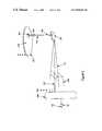
- FIG. 1illustrates a magneto-optical storage and retrieval system, generally illustrated in a top view:
- FIG. 2is a diagram showing one embodiment of the laser-optics assembly of the magneto-optical data storage and retrieval system of FIG. 1 ;
- FIG. 3is a diagram showing a representative optical path
- FIGS. 4A and 4Billustrate a comparison of the spectral output of a Fabry-Perot diode laser to that of a frequency-stabilized DFB laser diode source;
- FIGS. 5 and 6illustrate a representative structure of a DFB diode laser source and exemplary power vs. current characteristics, respectively;
- FIG. 7illustrates a DFB laser source
- FIGS. 8 a-care diagrams showing a magneto-optical head in a top view, a side cross-sectional view, and a front cross-sectional view, respectively;
- FIG. 9 a-billustrate two embodiments of a magneto-optical data storage and retrieval system as used in a magneto-optical disk drive.
- the magneto-optical (MO) data storage and retrieval system 100includes a set of Winchester-type flying heads 106 that are adapted for use with a set of double-sided first surface MO disks 107 (one flying head for each MO disk surface).
- the set of flying heads 106(hereinafter referred to as flying MO heads) are coupled to a rotary actuator magnet and coil assembly 120 by a respective suspension 130 and actuator arm 105 so as to be positioned over the surfaces of the set of MO disks 107 .
- the set of MO disks 107are rotated by a spindle motor 195 so as to generate aerodynamic lift forces between the set of flying MO heads 106 and so as to maintain the set of flying MO heads 106 in a flying condition approximately 15 micro-inches above the upper and lower surfaces of the set of MO disks 107 .
- the lift forcesare opposed by equal and opposite spring forces applied by the set of suspensions 130 .
- the set of flying MO heads 106are maintained statically in a storage condition away from the surfaces of the set of MO disks 107 .
- System 100further includes: a laser-optics assembly 101 , an optical switch 104 , and a set of single-mode polarization maintaining (PM) optical fibers 102 .
- Each of the set of single-mode PM optical fibers 102may be respectively coupled through a respective one of the set of actuator arms 105 and set of suspensions 130 to a respective one of the set of flying MO heads 106 .
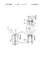
- FIG. 2is a diagram showing one embodiment of the laser-optics assembly of the magneto-optical data storage and retrieval system of FIG. 1 .
- the laser-optics assembly 101includes a linearly polarized distributed feedback (DFB) laser source 231 .
- the laser source 231operates at a single wavelength, preferably at 635-685 nm within a red region of the visible light spectrum; however, it is understood that laser sources operating at other wavelengths could also be used.
- the laser-optics assembly 101further includes: a collimating optics 234 , a low wavelength dispersion leaky beam splitter 232 , and a coupling lens 233 .
- the laser-optics assembly 101directs (from the linearly polarized laser source 231 ) a linearly polarized outgoing laser beam 191 (shown in FIG. 1 ) toward the optical switch 104 .
- Laser-optics assembly 101further includes: a 1 ⁇ 4 wave plate 238 , a mirror 235 , and a polarizing beam splitter 232 .
- a linearly polarized reflected laser beam 192(shown in FIG. 1 and discussed below) is directed by the optical switch 104 to the coupling lens 233 , and is routed by the leaky beam splitter 232 to a differential detector comprising: the 1 ⁇ 4 wave plate 238 , the mirror 235 , and the polarizing beam splitter 239 .
- the laser-optics assembly 101may further include an optical isolator 297 positioned between the laser source 231 and the collimating lens 234 .
- this type of differential detection schememeasures the optical power in two orthogonal polarization components of the reflected laser beam 192 , with a differential signal being a sensitive measure of polarization rotation induced by the Kerr effect at the surface of one of the set of MO disks 107 .
- the differential signalis processed by the differential amplifier 237 and is output as signal 294 .
- FIG. 3is a diagram showing a representative optical path that includes: the optical switch 104 , one of the set of single-mode PM optical fibers 102 , and one of the set of flying MO heads 106 .
- the optical switch 104provides degrees of selectivity so as to direct the outgoing laser beam 191 towards a respective proximal end of a respective single-mode PM optical fiber 102 .
- the linearly polarized outgoing laser beam 191 from the laser-optics assembly 101is preferably aligned in the optical path so as to enter the proximal end of the PM optical fiber 102 at an 45 degree angle relative to a fast axis of the PM optical fiber 102 .
- the outgoing laser beam 191is further directed by the single-mode PM optical fiber 102 to exit a respective distal end so as to pass through the flying MO head 106 onto a surface recording layer 349 of a respective MO disk 107 .
- FIGS. 4A and 4Billustrate a comparison of the spectral output of a Fabry-Perot diode laser ( FIG. 4A ) to the spectral output of a frequency-stabilized DFB laser diode source (FIG. 4 B).
- the DFB laser source 231is a distributed feedback (DFB) diode laser source.
- a DFB laser source 231unlike an RF-modulated Fabry-Perot diode laser, produces a very narrowband single-frequency output due to the use of a wavelength selective grating element inside the laser cavity.
- the present inventionidentifies that when linearly polarized light from a DFB laser source 231 is launched into the single-mode PM optical fiber 102 , the light exiting the optical fiber comprises a polarization state that depends on the relative orientation between the fiber axes and the incident polarization, and moreover, the output polarization state is very stable in time as long as external perturbations which alter the fiber birefringence are negligible. This behavior contrasts to that observed when using prior art RF-modulated Fabry-Perot diode laser sources.
- Fabry-Perot laser diodesare characterized by high-frequency fluctuations in their spectral output; therefore, when linearly polarized light Is launched into a single-mode PM optical fiber 102 , fluctuations in the laser wavelength fluctuations lead to corresponding polarization fluctuations in the laser light exiting the output of the optical fiber.
- the resulting polarization noiseis larger than the corresponding DFB diode laser source case owing to wavelength dependent mode coupling.
- Mode coupling in PM fibersis a phenomenon whereby a small portion of the light that is being guided along one polarization axis is coupled into the orthogonal axis by intrinsic or stress-induced defects.
- MO recordingit is important that the polarization noise be kept to a minimum, such that an SNR in the range of 20-25 dB can be achieved.
- a DFB laser source 231it is possible to achieve the aforementioned level of SNR in the magneto-optical (MO) data storage and retrieval system 100 when utilizing the single-mode PM optical fiber 102 for the delivery and return of polarized light to and from the MO disk 107 .
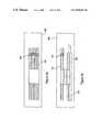
- FIGS. 5 and 6illustrate representative structure of a DFB diode laser source and exemplary power vs. current characteristics, respectively.
- DFB diode laser sourcesutilize buried grating layer structures 552 in order to stabilize the laser wavelength.
- a DFB diode laser's performancedegrades as damage occurs to it's facets 551 (only the front facet labeled).
- the facetsare passivated with a coating to prevent oxygen from reaching the facet.
- the coatingcan also be designed to thermally heat-sink the facets, cooling the laser source 231 so as to permit increased laser source output power and thus reduce concomitant damage to the facets.
- DFB laser diodes as discussed aboveare developed by SDL Inc., San Jose, Calif.
- FIG. 7illustrates a DFB laser source 754 proposed to operate as a GaN single-frequency blue diode laser source 754 .
- the active layer of the laser sourceconsists of InGaN wells 756 , roughly 50 A thick, sandwiched between thin InGaN layers of low in content. This mule quantum-well structure is bounded by thicker GaN layers 755 to form a separate confinement hetrostucture.
- the coreis itself surrounded by AlGaN cladding layers 753 roughly 0.5 ⁇ m thick.
- the entire structureis grown on a GaN buffer 757 approximately 3 ⁇ m in thickness, atop a substrate 758 which is typically sapphire, spinel, or SiC.
- a single-frequency devicecan be formed by introducing a grating layer 759 which couples the output into a single longitudinal mode.
- the architecture discussed for single-frequency GaN DFB structuresis similar to that of the red laser source 231 described above; however, blue GaN DFB laser diodes require shorter period gratings. It is understood that single frequency properties of diode laser sources such as distributed Bragg reflector (DBR) laser diodes may also being utilized with the single-mode PM optical fibers 102 .
- DBRdistributed Bragg reflector
- the outgoing laser beam 191is selectively routed by the optical switch 104 to the MO disk 107 so as to lower a coercivity of the surface recording layer 349 by heating a selected spot of interest 340 to approximately the Curie point of the MO recording layer 349 .
- the optical intensity of outgoing laser beam 191is held constant at a power on a range of 30-40 mw, while a time varying vertical bias magnetic field is used to define a pattern of “up” or “down” magnetic domains perpendicular to the MO disk 107 . This technique is known as magnetic field modulation (MFM).
- MFMmagnetic field modulation
- outgoing laser beam 191may be modulated in synchronization with the time varying vertical bias magnetic field at the spot of interest 340 in order to better control domain wall locations and reduce domain edge jitter. Subsequently, as the selected spot of interest 340 cools at the surface layer 349 , information is encoded at the surface of the respective spinning disk 107 .
- the outgoing laser beam 191(at a lower power compared to writing) is selectively routed to the MO disk 107 such that at any given spot of interest 340 the Kerr effect causes (upon reflection of the outgoing laser beam 191 from the surface layer 349 ) a reflected laser beam 192 to have a rotated polarization of either clockwise or counter clockwise sense 363 that depends on the magnetic domain polarity at the spot of interest 340 .
- the aforementioned optical pathis bi-directional in nature. Accordingly, the reflected laser beam 192 is received through the flying MO head 106 and enters the distal end of the single-mode PM optical fiber 102 . The reflected laser beam 192 propagates along the single-mode PM optical fiber 102 to exit at its proximal end and is selectively routed by the optical switch 104 for transmission to laser-optics assembly 101 for subsequent optical and electronic conversion.
- FIGS. 8- a-care diagrams showing a magneto-optical head in a top view, a side cross-sectional view, and a front cross-sectional view, respectively.
- the set of flying MO headsmay be illustrated with reference to a single representative flying MO head 106 .
- a single representative flying MO head 106is shown in FIGS. 8- b-c to be positioned respectively above a surface recording layer 349 of one of the set of spinning MO disks 107 .
- the flying MO head 106includes: a slider body 844 , an air bearing surface 847 , a transmissive quarter-wave plate 893 , a steerable micro-machined mirror assembly 800 , an objective optics 846 , and a magnetic coil 860 in an exemplary embodiment, the magnetic coil 860 is a micro multi-turn coil positioned near the air-bearing surface 847 so as to generate a magnetic field that is: approximately 300 Oersteds of either polarity, reversible in a time of about 4 ns, and approximately perpendicular to the plane of the spinning MO disk 107 .
- the magnetic coilshould not interfere with the outgoing and reflected laser beams 191 and 192 during passage through the flying MO head 106 to the spinning MO disk 107 , or vice versa.
- the slider body 844includes a height of approximately 889 urn and a planar footprint area that corresponds to that of a nano slider (2032 urn ⁇ 1600 um).
- the quarter-wave plate 893includes a square dimension of approximately 250 um, a thickness of approximately 89 um, and a phase retardation of about 90 degrees (+/ ⁇ 3 degrees) at a wavelength of interest.
- Single-mode PM optical fiber 102is preferably coupled to the flying MO head 106 and is held along an axis of the slider body 844 by a v-groove 843 or other suitably dimensioned channel.
- the single-mode PM optical fiber 102is positioned within the v-groove 843 to preferably direct the outgoing laser beam 191 as an optimally focused optical spot 848 .
- the single-mode PM optical fiber 102may be subsequently secured in place by using an ultraviolet curing epoxy or a similar adhesive. Use of the PM optical fiber 102 within a V-groove permits accurate alignment and delivery of the outgoing laser beam 191 relative to the small mirror assembly 800 .
- the steerable micro-machined mirror assembly 800 , the quarter-wave plate 893 , and objective optics 846are preferably compact and low mass so as to fit within a physical volume defined approximately the rectangular outer dimensions of the slider body 844 and yet sufficiently large to direct a full cross section of the outgoing and reflected laser beams 191 and 192 so that minimal power is lost and significant distortion and aberrations in the outgoing and reflected laser beams 191 and 192 are not introduced.
- the steerable micro-machined mirror assembly 800is aligned in the representative optical path so as to direct the outgoing laser beam 191 through the objective optics 846 and quarter-wave plate 893 and so as to direct the reflected laser beam 192 from the MO disk 107 back to the laser optics assembly 101 .
- the objective optics 846may be a microlens with a numerical aperture (NA) of approximately 0.67. In an exemplary embodiment, at a wavelength of 650 nm, the micro-lens focuses the optical spot 848 with a full width at half-maximum intensity (FWHM) of approximately 0.54 um.
- the microlensmay be a GRIN (Graded Index) lens 846 , of simple and compact cylindrical shape.
- a cylindrical shapepermits the lens 846 to be easily inserted into a simple receiving aperture provided in the slider body 844 .
- the GRIN lens 846may be polished to assume a plano-convex shape, with the convex surface being a simple spherical shape.
- the desired thickness and radius of curvature of the GRIN lens 846is a function of a number of factors including: the magnitude of the refractive index gradient, the wavelength of light, the numerical aperture of the PM optical fiber 102 , and the desired focused optical spot 848 size.
- the GRIN lens 846 heightis approximately 350 um
- the radius of curvatureis approximately 200 um
- the lens diameteris approximately 250 um.
- the optimum focusoccurs on the planar side of the GRIN lens 846 and preferably comprises a depth of focus that Is approximately 25 micro-inches. Because flying height of the air bearing surface 847 is preferably maintained at a value to be approximately 15 micro-inches, a focusing servo is not necessarily required.
- the single-mode PM optical fiber 102functions as an aperture of a confocal optical system that has a large depth resolution along its optical axis and an improved transverse resolution.
- the improved transverse resolutionimproves the detection of smaller magnetic domain orientations as well as detection of magnetic domain edges as compared to a nonconfocal system.
- the large depth resolutionminimizes cross-talk between closely spaced surface recording levels when using multi-level storage media.
- Another advantage that arises from the confocal nature of the present inventionis that stray light reflected from the objective optics 846 is filtered.
- fine tracking and short seeks to nearby tracksare performed by rotating a reflective central mirror portion of the steerable micro-machined mirror assembly 800 about a rotation axis so that the propagation angle of the outgoing laser beam 191 is changed before transmission to the objective optics 846 .
- a suitable micro-machined mirror assemblyis disclosed in commonly assigned U.S. patent application Ser. No. 08/823,422, entitled “Optical Head Using Micro-Machined Elements, filed on 24 Mar. 1997.
- the reflective central mirror portionis rotated by applying a differential voltage to drive electrodes.
- the differential voltagecreates an electrostatic force that rotates the reflective central minor portion about an axis and enables the focused optical spot 848 to be moved in the radial direction 850 on the MO media 107 .
- the central mirror portionrotates approximately +/ ⁇ 2 degrees, which is equivalent to approximately +/ ⁇ 4 tracks at the surface of the MO disk 107 .
- a movement of +1-4 tracksis disclosed, depending on the desired performance characteristics of the steerable micro-machined mirror 800 described above, a range of movement greater or fewer than +/ ⁇ 4 tracks is understood to also be possible.
- movement of the focused optical spot 848 across the MO disk 107 and detection of the reflected laser beam 192may be used in storage and retrieval of information, track following, and seeks from one data track to another data track.
- Coarse trackingmay be maintained by adjusting a current to rotary actuator magnet and coil assembly 120 (FIG. 1 ).
- the track following signals used to follow a particular track of the MO disk 107may be derived using combined coarse and fine tracking servo techniques that are well known in the art.
- a sampled sector servo formatmay be used to define tracks.
- the servo formatmay include either embossed pits stamped into the MO disk 107 or magnetic domain orientations that are read similar to data marks.
- an adder output circuitmay be used to supplement the differential output circuit 237 (FIG. 2 ).
- Those skilled id the artwill recognize that conventional prior art multiple magnetic disk Winchester magnetic disk drives use a set of respective suspensions and actuator arms that move in tandem as one integral unit. Therefore, because each flying head of such an integral unit is fixed relative to another flying head, during track following of a particular magnetic disk surface, simultaneous track following of another magnetic disk surface is not possible.
- a set of steerable micro-machined mirror assemblies 800may be used to operate independently and thus permit track following and seeks so as to read and/or write information using more than one MO disk surface at any given time.
- Independent track following and seeks using a set of concurrently operating steerable micro-machined assemblies 800preferably requires a set of separate respective read channel and fine track electronics and mirror driving electronics. Because the aforementioned embodiment would also preferably require use of separate laser-optics assemblies 101 , an optical switch 104 for switching between each of the separate optical paths in and not necessarily be required.
- FIG. 9 ais a diagram showing a magneto-optical data storage and retrieval system as part of a magneto-optical disk drive.
- the magneto-optical system 100comprises a compact high-speed and high-capacity MO disk drive 908 that includes an industry standard 5.25 inch half-height form factor (1.625 inch), at least six double-sided MO disks 107 , and at least twelve flying MO heads 106 .
- the flying MO heads 106may be manufactured to include PM optical fibers 102 as part of a very small mass and low profile high NA optical system so as to enable utilization of multiple MO disks 107 at a very dose spacing within the MO disk drive 908 and; therefore, to comprise a higher areal and volumetric and storage capacity than is permitted in art equivalent volume of the prior art in the preferred embodiment, a spacing between each of the at least six MO disks 107 can be reduced to at least 0.182 inches.
- the present inventionidentifies that by using a single frequency laser source such as distributed feedback (DFB) laser diode 231 , a polarization state conveyed by the PM optical fibers 102 may be conveyed with significantly reduced noise over that when used with conventional Fabry-Perot diode lasers.
- a single frequency laser sourcesuch as distributed feedback (DFB) laser diode 231
- DFBdistributed feedback
- the half-height form factor MO disk drive 908may include a removable MO disk cartridge portion 910 and two fixed internal MO disks 107 .
- the removable MO disk cartridge portion 910By providing the removable MO disk cartridge portion 910 , the fixed internal and removable combination permits external information to be efficiently delivered to the MO disk drive 908 for subsequent transfer to the internal MO disks 107 . The copied information may, subsequently, be recorded back onto the removable MO disk cartridge portion 910 for distribution to other computer systems.
- the removable MO disk cartridge portion 910allows for very convenient and high speed back-up storage of the internal MO spinning disks 107 .
- the fixed internal and removable combinationalso permits storage of data files on the removable MO disk cartridge portion 910 and system files and software applications on the internal MO spinning disks 107 .
- an MO disk drive 908may include: any number (including zero) of internal MO disks 107 and/or any number of MO disks 107 within any number of removable MO disk cartridge portions.
- the present inventiondoes not necessarily require use of rotary actuator arms, for example, linear actuator arms may be used.
- the low profile optical paths disclosed by the present inventionmay be used to convey information to and from a storage location without requiring objective optics (e.g., using a tapered optical fiber or an optical fiber with a lens formed on an end); and/or reflective substrates (e.g., using a curved optical fiber to convey information along surfaces of the magneto-optical head 106 ).
Landscapes
- Physics & Mathematics (AREA)
- Optics & Photonics (AREA)
- General Physics & Mathematics (AREA)
- Engineering & Computer Science (AREA)
- Electromagnetism (AREA)
- Microelectronics & Electronic Packaging (AREA)
- Computer Networks & Wireless Communication (AREA)
- Signal Processing (AREA)
- Computer Hardware Design (AREA)
- Optical Head (AREA)
Abstract
Description
Claims (14)
Priority Applications (2)
| Application Number | Priority Date | Filing Date | Title |
|---|---|---|---|
| US08/883,320US6850475B1 (en) | 1996-07-30 | 1997-06-26 | Single frequency laser source for optical data storage system |
| PCT/US1997/015212WO1998009280A1 (en) | 1996-08-27 | 1997-08-27 | Single-frequency laser source for optical data storage system |
Applications Claiming Priority (5)
| Application Number | Priority Date | Filing Date | Title |
|---|---|---|---|
| US2277596P | 1996-07-30 | 1996-07-30 | |
| US2347696P | 1996-08-06 | 1996-08-06 | |
| US2580196P | 1996-08-27 | 1996-08-27 | |
| US82342297A | 1997-03-24 | 1997-03-24 | |
| US08/883,320US6850475B1 (en) | 1996-07-30 | 1997-06-26 | Single frequency laser source for optical data storage system |
Related Parent Applications (1)
| Application Number | Title | Priority Date | Filing Date |
|---|---|---|---|
| US82342297AContinuation-In-Part | 1996-07-30 | 1997-03-24 |
Publications (1)
| Publication Number | Publication Date |
|---|---|
| US6850475B1true US6850475B1 (en) | 2005-02-01 |
Family
ID=32996236
Family Applications (3)
| Application Number | Title | Priority Date | Filing Date |
|---|---|---|---|
| US08/883,320Expired - LifetimeUS6850475B1 (en) | 1996-07-30 | 1997-06-26 | Single frequency laser source for optical data storage system |
| US09/271,440Expired - Fee RelatedUS6798729B1 (en) | 1996-07-30 | 1999-03-18 | Optical head using micro-machined elements |
| US09/587,063Expired - LifetimeUS6360035B1 (en) | 1996-07-30 | 2000-06-02 | Optical head using micro-machined elements |
Family Applications After (2)
| Application Number | Title | Priority Date | Filing Date |
|---|---|---|---|
| US09/271,440Expired - Fee RelatedUS6798729B1 (en) | 1996-07-30 | 1999-03-18 | Optical head using micro-machined elements |
| US09/587,063Expired - LifetimeUS6360035B1 (en) | 1996-07-30 | 2000-06-02 | Optical head using micro-machined elements |
Country Status (1)
| Country | Link |
|---|---|
| US (3) | US6850475B1 (en) |
Cited By (8)
| Publication number | Priority date | Publication date | Assignee | Title |
|---|---|---|---|---|
| US20030112542A1 (en)* | 2001-12-18 | 2003-06-19 | Rettner Charles T. | Optical aperture for data recording having transmission enhanced by surface plasmon resonance |
| US20030123335A1 (en)* | 2001-12-18 | 2003-07-03 | International Business Machines Corporation | Optical aperture for data recording having transmission enhanced by waveguide mode resonance |
| US8379495B2 (en)* | 2008-12-31 | 2013-02-19 | HGST Netherlands B.V. | System, method and apparatus for internal polarization rotation for horizontal cavity, surface emitting laser beam for thermally assisted recording in disk drive |
| US8422342B1 (en)* | 2010-06-25 | 2013-04-16 | Western Digital (Fremont), Llc | Energy assisted magnetic recording disk drive using a distributed feedback laser |
| US8441896B2 (en) | 2010-06-25 | 2013-05-14 | Western Digital (Fremont), Llc | Energy assisted magnetic recording head having laser integrated mounted to slider |
| US9202489B2 (en) | 2014-01-24 | 2015-12-01 | Seagate Technology Llc | Laser mounted on edge of a slider |
| US9581188B2 (en) | 2011-12-12 | 2017-02-28 | Commissariat A L'energie Atomique Et Aux Energies Alternatives | Mechanical connection forming a pivot for MEMS and NEMS mechanical structures |
| TWI610450B (en)* | 2005-05-13 | 2018-01-01 | 半導體能源研究所股份有限公司 | Semiconductor device and method of manufacturing same |
Families Citing this family (51)
| Publication number | Priority date | Publication date | Assignee | Title |
|---|---|---|---|---|
| US6301403B1 (en)* | 1996-07-30 | 2001-10-09 | Iolon, Inc. | Optical microswitch with rotary electrostatic microactuator |
| US6328482B1 (en)* | 1998-06-08 | 2001-12-11 | Benjamin Bin Jian | Multilayer optical fiber coupler |
| JP2001117026A (en)* | 1999-10-19 | 2001-04-27 | Sony Corp | Micro mirror device and optical disk device |
| US7219165B1 (en)* | 2000-01-14 | 2007-05-15 | G&H Nevada Tek | High-speed data transfer in a networked server environment via laser communication |
| US7970950B1 (en) | 2007-04-09 | 2011-06-28 | G&H Nevada—Tek | High-speed data transfer in a networked server environment via laser communication |
| WO2001053872A1 (en)* | 2000-01-18 | 2001-07-26 | Cornell Research Foundation, Inc. | Single crystal silicon micromirror and array |
| US20010040419A1 (en) | 2000-03-24 | 2001-11-15 | Behrang Behin | Biased rotatable combdrive sensor methods |
| US6612029B2 (en) | 2000-03-24 | 2003-09-02 | Onix Microsystems | Multi-layer, self-aligned vertical combdrive electrostatic actuators and fabrication methods |
| JP2001281506A (en)* | 2000-03-31 | 2001-10-10 | Ngk Insulators Ltd | Optical head |
| US6785086B1 (en)* | 2000-04-05 | 2004-08-31 | Seagate Technology Llc | Transducer-level microactuator with dual-axis control |
| US7190854B1 (en) | 2000-05-24 | 2007-03-13 | Active Optical Networks, Inc. | Methods for forming an array of MEMS optical elements |
| US6963679B1 (en)* | 2000-05-24 | 2005-11-08 | Active Optical Networks, Inc. | Micro-opto-electro-mechanical switching system |
| US20020008922A1 (en)* | 2000-05-31 | 2002-01-24 | Conant Robert A. | Actuator and micromirror for fast beam steering and method of fabricating the same |
| US7346093B2 (en)* | 2000-11-17 | 2008-03-18 | Cymer, Inc. | DUV light source optical element improvements |
| US6678437B2 (en)* | 2001-03-30 | 2004-01-13 | Analog Devices, Inc. | Method of and architecture for optically switching light communication signals in fiber optic networks and the like |
| US6526197B2 (en)* | 2001-04-09 | 2003-02-25 | Adc Telecommunications, Inc. | MEMS optical balanced path switch |
| US6760196B1 (en)* | 2001-12-12 | 2004-07-06 | Western Digital, Inc. | Microactuator with offsetting hinges and method for high-resolution positioning of magnetic read/write head |
| US6809848B2 (en)* | 2001-06-01 | 2004-10-26 | Agere Systems Inc. | MEMS device |
| US7755867B2 (en)* | 2001-07-16 | 2010-07-13 | Seagate Technology Llc | Controlled air bearing (CAB) for magnetic spacing control |
| US6836585B2 (en)* | 2001-08-06 | 2004-12-28 | Fiberyard, Inc. | Photonic switch |
| US6886234B2 (en)* | 2002-01-22 | 2005-05-03 | Seagate Technology Llc | Top cover removal machine for disc drives |
| EP1398766A3 (en)* | 2002-08-13 | 2005-08-17 | Lg Electronics Inc. | Micro-actuator, manufacturing method thereof, optical pickup head of optical recording/reproducing apparatus with micro-actuator and fabrication method thereof |
| JP2005092174A (en)* | 2003-08-12 | 2005-04-07 | Fujitsu Ltd | Micro oscillating device |
| DE102004037833A1 (en)* | 2003-08-25 | 2005-03-31 | Advanced Nano Systems Inc., San Jose | Micro-electro-mechanical system scanning mirror device for laser printer, has springs that connect beam structure which is supporting scanning mirror by several support attachment, to stationary support structure |
| US7014115B2 (en)* | 2003-08-25 | 2006-03-21 | Advanced Nano Systems, Inc. | MEMS scanning mirror with distributed hinges and multiple support attachments |
| US7203395B2 (en)* | 2003-10-10 | 2007-04-10 | Japan Aviation Electronics Industry Limited | Miniature movable device |
| US7173795B2 (en)* | 2003-12-09 | 2007-02-06 | Headway Technologies, Inc. | Bias point adjustment of a read head by means of an external magnet |
| US7542188B2 (en)* | 2004-01-20 | 2009-06-02 | National University Of Singapore | Optical scanning using vibratory diffraction gratings |
| KR101091129B1 (en) | 2004-02-09 | 2011-12-09 | 세이코 엡슨 가부시키가이샤 | Mems scanner adapted to a laser printer |
| US7482730B2 (en)* | 2004-02-09 | 2009-01-27 | Microvision, Inc. | High performance MEMS scanner |
| JP2005317178A (en)* | 2004-03-29 | 2005-11-10 | Sharp Corp | RECORDING / REPRODUCING DEVICE, RECORDING MEDIUM, RECORDING / REPRODUCING DEVICE DRIVING METHOD, SEMICONDUCTOR LASER LIFE PREDICTION METHOD, PROGRAM, PROGRAM RECORDING MEDIUM, SEMICONDUCTOR LASER |
| US7442918B2 (en)* | 2004-05-14 | 2008-10-28 | Microvision, Inc. | MEMS device having simplified drive |
| US7310242B2 (en)* | 2004-05-21 | 2007-12-18 | General Motors Corporation | Self-shielding high voltage distribution box |
| US7636101B2 (en)* | 2005-02-09 | 2009-12-22 | Microvision, Inc. | MEMS scanner adapted to a laser printer |
| US7839497B1 (en)* | 2006-07-13 | 2010-11-23 | Seagate Technology Llc | Phase compensator for coupling an electromagnetic wave into an optical condenser |
| US8003176B2 (en)* | 2006-10-04 | 2011-08-23 | 3M Innovative Properties Company | Ink receptive article |
| US8012550B2 (en)* | 2006-10-04 | 2011-09-06 | 3M Innovative Properties Company | Ink receptive article |
| JP5049017B2 (en)* | 2007-01-05 | 2012-10-17 | エイチジーエスティーネザーランドビーブイ | Magnetic disk drive and manufacturing method thereof |
| US8027123B2 (en)* | 2007-12-19 | 2011-09-27 | Hitachi Global Storage Technologies, Netherlands, B.V. | Integrated windage blocker for reduction of flex cable vibration in a disk drive |
| US8085508B2 (en)* | 2008-03-28 | 2011-12-27 | Hitachi Global Storage Technologies Netherlands B.V. | System, method and apparatus for flexure-integrated microactuator |
| EP2207190B9 (en)* | 2009-01-08 | 2014-09-24 | Epcos AG | Resilient device |
| JP2010176756A (en)* | 2009-01-30 | 2010-08-12 | Hitachi Ltd | Magnetic disk device |
| EP2435355B1 (en)* | 2009-05-29 | 2018-10-24 | DigitalOptics Corporation MEMS | Mechanical isolation for mems electrical contacts |
| US8624471B1 (en)* | 2010-07-30 | 2014-01-07 | Georgia Tech Research Corporation | Piezoelectric-on-semiconductor micromechanical resonators with linear acoustic bandgap tethers |
| DE102013209814B4 (en) | 2013-05-27 | 2015-01-22 | Fraunhofer-Gesellschaft zur Förderung der angewandten Forschung e.V. | Optical structure with webs disposed thereon and method of making the same |
| US8885280B1 (en)* | 2013-06-03 | 2014-11-11 | Seagate Technology Llc | Polarization rotator |
| US9369208B2 (en)* | 2014-02-21 | 2016-06-14 | Optomedia Technology Inc. | Optical communication module |
| US9437229B2 (en) | 2014-04-09 | 2016-09-06 | Seagate Technology Llc | Isolator element for heat-assisted magnetic recording |
| US10211757B2 (en) | 2015-08-04 | 2019-02-19 | Mems Drive, Inc. | Multi-directional actuator |
| CN112334867A (en) | 2018-05-24 | 2021-02-05 | 纽约州立大学研究基金会 | Capacitive sensor |
| US11892619B2 (en)* | 2019-09-04 | 2024-02-06 | Lumentum Operations Llc | MEMS device with a three-layer comb actuator structure and a two-layer hinge |
Citations (65)
| Publication number | Priority date | Publication date | Assignee | Title |
|---|---|---|---|---|
| US3737236A (en) | 1972-01-03 | 1973-06-05 | Corning Glass Works | Magnetooptic readout system utilizing optical waveguide fibers |
| US4003059A (en) | 1974-02-07 | 1977-01-11 | Canon Kabushiki Kaisha | Optical recorder having focus controlling means |
| US4135083A (en) | 1976-05-12 | 1979-01-16 | U.S. Philips Corporation | Optical scanning device |
| GB2016744A (en) | 1978-03-16 | 1979-09-26 | Philips Nv | Optical read/write apparatus |
| US4298245A (en) | 1978-09-21 | 1981-11-03 | Siemens Aktiengesellschaft | Waveguides with a low birefringence |
| US4337531A (en) | 1980-05-12 | 1982-06-29 | Northern Telecom Limited | Scanning head for an optical disc system |
| US4449204A (en)* | 1980-03-31 | 1984-05-15 | Agency Of Industrial Science And Technology | Information processing apparatus using a semiconductor laser diode |
| JPS59117180A (en) | 1982-12-23 | 1984-07-06 | Toshiba Corp | Semiconductor light-emitting element |
| US4510544A (en) | 1981-10-16 | 1985-04-09 | Compagnie Internationale Pour L'informatique Cii-Honeywell Bull | Optoelectronic device for reading data contained on a magnetic medium |
| US4532619A (en)* | 1982-01-22 | 1985-07-30 | Hitachi, Ltd. | Method and apparatus for reducing semiconductor laser optical noise |
| US4539519A (en) | 1981-04-23 | 1985-09-03 | Max-Planck-Gesellschaft Zur Forderung Der Wissenschaften E.V. | Fiber optics device for measuring the intensity of an electric current utilizing the Faraday effect |
| US4581529A (en) | 1983-08-15 | 1986-04-08 | At&T Bell Laboratories | Read/write system for optical disc apparatus with fiber optics |
| US4609871A (en) | 1984-07-02 | 1986-09-02 | The United States Of America As Represented By The Secretary Of The Navy | Temperature compensated optical fiber interferometric magnetometer |
| US4626679A (en) | 1982-09-22 | 1986-12-02 | Canon Kabushiki Kaisha | Optical head and method of detecting the focus thereof |
| US4683421A (en) | 1985-03-29 | 1987-07-28 | Westinghouse Electric Corp. | Drift compensation technique for a magneto-optic current sensor |
| US4740951A (en) | 1985-03-13 | 1988-04-26 | Commissariat A L'energie Atomique | Reversible device for the demultiplexing of several light signals in integrated optics |
| US4796226A (en) | 1986-11-18 | 1989-01-03 | Commissariat A L'energie Atomique | Reading head in integrated optics for reading information recorded on a magnetic support |
| US4799210A (en) | 1986-11-05 | 1989-01-17 | Unisys Corporation | Fiber optic read/write head for an optical disk memory system |
| US4806885A (en) | 1986-08-08 | 1989-02-21 | Sumitomo Electric Industries, Ltd. | Magnet-electro-optic effect light modulator |
| US4847823A (en) | 1987-06-19 | 1989-07-11 | Siscan Systems, Inc. | Method and apparatus for reading or measuring magneto-optical storage media using pinhole aperture |
| EP0331331A2 (en) | 1988-03-03 | 1989-09-06 | AT&T Corp. | Subassembly for optoelectronic devices |
| US4866372A (en) | 1987-05-31 | 1989-09-12 | Hamamatsu Photonics Kabushiki Kaisha | Voltage detector having compensation for polarization change caused by spontaneous birefringence |
| US4945400A (en) | 1988-03-03 | 1990-07-31 | At&T Bell Laboratories | Subassembly for optoelectronic devices |
| US4978187A (en)* | 1988-05-27 | 1990-12-18 | Hitachi, Ltd. | Optical element, optical disc and rotary encoder with the optical element |
| US5029023A (en)* | 1989-09-29 | 1991-07-02 | Regents Of The University Of California | Laser-amplified motion detector and method |
| US5033043A (en) | 1989-04-19 | 1991-07-16 | Eastman Kodak Company | Optical head apparatus for optical disks |
| US5034679A (en) | 1989-12-14 | 1991-07-23 | Sundstrand Corporation | Polarization feedback control of polarization rotating sensor |
| US5039220A (en) | 1988-09-14 | 1991-08-13 | Phononetics, S.A. | Optical fiber measuring device, gyrometer, central navigation and stabilizing system |
| EP0460890A2 (en) | 1990-06-06 | 1991-12-11 | Texas Instruments Incorporated | Optical tracking system |
| US5111326A (en)* | 1991-04-25 | 1992-05-05 | United Technologies Corporation | Integrated Kerr shutter and fiber laser optical modulation |
| US5119361A (en) | 1988-09-29 | 1992-06-02 | Asahi Glass Company Ltd. | Optical information readout apparatus |
| US5124961A (en) | 1989-12-28 | 1992-06-23 | Fuji Xerox Co., Ltd. | Floating head for use with a recording apparatus of magneto-optical memory device |
| US5135295A (en) | 1990-02-27 | 1992-08-04 | Queen's University At Kingston | Fiber-optic piezoelectric devices |
| US5137359A (en) | 1991-03-18 | 1992-08-11 | Litton Systems, Inc. | Digital phase modulator for fiber optic sagnac interferometer |
| US5152597A (en) | 1990-12-03 | 1992-10-06 | Eastman Kodak Company | Magneto-optic readout using a polarization-preserving optical fiber |
| US5164956A (en) | 1991-10-21 | 1992-11-17 | The United States Of America As Represented By The Administrator Of The National Aeronautics And Space Administration | Multiperiod-grating surface-emitting lasers |
| US5191387A (en) | 1990-01-10 | 1993-03-02 | Ando Electric Co., Ltd. | Polarization control system |
| US5199090A (en) | 1992-03-06 | 1993-03-30 | Hewlett-Packard Company | Flying magnetooptical read/write head employing an optical integrated circuit waveguide |
| US5212583A (en) | 1992-01-08 | 1993-05-18 | Hughes Aircraft Company | Adaptive optics using the electrooptic effect |
| US5218582A (en) | 1990-12-03 | 1993-06-08 | Eastman Kodak Company | Magneto-optic readout using a polarization-preserving optical guide |
| US5229834A (en) | 1990-01-12 | 1993-07-20 | Bertin & Cie | Sensor for detecting and measuring the angle of rotation of a plane of light polarization |
| US5233444A (en)* | 1989-07-25 | 1993-08-03 | Olympus Optical Co., Ltd. | Focus error detecting apparatus |
| US5245491A (en) | 1989-06-02 | 1993-09-14 | Hitachi Cable Limited | Magneto-optical head employing optical fiber connected stationary and movable portions |
| US5278812A (en)* | 1992-02-18 | 1994-01-11 | At&T Bell Laboratories | Tracking and focussing functions in optical disk apparatus |
| US5296988A (en) | 1991-05-20 | 1994-03-22 | Canon Kabushiki Kaisha | Optical head with an adjusting mechanism for adjusting the position of an optical mirror |
| US5311360A (en) | 1992-04-28 | 1994-05-10 | The Board Of Trustees Of The Leland Stanford, Junior University | Method and apparatus for modulating a light beam |
| US5323373A (en)* | 1991-07-11 | 1994-06-21 | Sony Corporation | Optical pickup device |
| US5325116A (en) | 1992-09-18 | 1994-06-28 | Texas Instruments Incorporated | Device for writing to and reading from optical storage media |
| EP0614101A2 (en) | 1993-02-03 | 1994-09-07 | Canon Kabushiki Kaisha | Optical deflector and method of manufacturing the same |
| US5383048A (en) | 1993-02-03 | 1995-01-17 | Seaver; George | Stress-optical phase modulator and modulation system and method of use |
| EP0650133A2 (en) | 1993-10-25 | 1995-04-26 | Symbol Technologies, Inc. | Integrated scanner on a common substrate |
| WO1995013638A1 (en) | 1993-11-08 | 1995-05-18 | International Business Machines Corporation | Hybrid external coupled cavity semiconductor laser device |
| US5446574A (en) | 1993-03-26 | 1995-08-29 | Telefonaktiebolaget Lm Ericsson | System and method for dispersion compensation in fibre optic high speed systems |
| US5448548A (en)* | 1992-10-21 | 1995-09-05 | Sharp Kabushiki Kaisha | Optical information reading method for reducing laser noise using a semiconductor laser and a driving device for the semiconductor laser |
| US5477323A (en) | 1992-11-06 | 1995-12-19 | Martin Marietta Corporation | Fiber optic strain sensor and read-out system |
| US5483607A (en) | 1993-05-11 | 1996-01-09 | Martin Marietta Corporation | Two-mode remote fiber optic sensor |
| US5493220A (en) | 1993-03-05 | 1996-02-20 | Northeastern University | Magneto-optic Kerr effect stress sensing system |
| US5495456A (en)* | 1993-09-29 | 1996-02-27 | Sony Corporation | Magneto-optical recording and reproducing apparatus having a laser driving circuit which superimposes a signal having a frequency at least double the maximum recording signal frequency |
| US5495464A (en)* | 1993-01-20 | 1996-02-27 | Olympus Optical Co., Ltd. | Optical data recording/reproducing apparatus |
| EP0712121A2 (en) | 1994-11-10 | 1996-05-15 | Kabushiki Kaisha Toshiba | Galvanomirror and optical disk drive using the same |
| US5521999A (en)* | 1994-03-17 | 1996-05-28 | Eastman Kodak Company | Optical system for a laser printer |
| US5536926A (en) | 1993-12-22 | 1996-07-16 | Omron Corporation | Optical scanner and optical scanning device, optical sensor, coded data reader, and POS system which employ the optical scanner |
| US5625483A (en) | 1990-05-29 | 1997-04-29 | Symbol Technologies, Inc. | Integrated light source and scanning element implemented on a semiconductor or electro-optical substrate |
| US5633959A (en) | 1994-10-11 | 1997-05-27 | Advantest Corporation | Polarization state changing apparatus and polarization degree measuring apparatus using the same |
| US5742419A (en) | 1995-11-07 | 1998-04-21 | The Board Of Trustees Of The Leland Stanford Junior Universtiy | Miniature scanning confocal microscope |
Family Cites Families (68)
| Publication number | Priority date | Publication date | Assignee | Title |
|---|---|---|---|---|
| JPS53108403A (en) | 1977-03-04 | 1978-09-21 | Sony Corp | Mirror supporting device for video disc |
| US4304460A (en) | 1978-03-10 | 1981-12-08 | Matsushita Electric Industrial Co., Ltd. | Optical switching device |
| US4265513A (en) | 1978-08-17 | 1981-05-05 | Nippon Electric Co., Ltd. | Light switch |
| US4239330A (en) | 1978-10-18 | 1980-12-16 | Bell Telephone Laboratories, Incorporated | Multiple optical switch |
| JPS55105210A (en) | 1979-02-08 | 1980-08-12 | Nec Corp | Photo switch element |
| US4626066A (en) | 1983-12-30 | 1986-12-02 | At&T Bell Laboratories | Optical coupling device utilizing a mirror and cantilevered arm |
| US4674319A (en) | 1985-03-20 | 1987-06-23 | The Regents Of The University Of California | Integrated circuit sensor |
| JPS62222455A (en)* | 1985-12-24 | 1987-09-30 | Seiko Epson Corp | Optical information recording and reproducing device |
| GB8707854D0 (en) | 1987-04-02 | 1987-05-07 | British Telecomm | Radiation deflector assembly |
| US4805456A (en) | 1987-05-19 | 1989-02-21 | Massachusetts Institute Of Technology | Resonant accelerometer |
| US4943750A (en) | 1987-05-20 | 1990-07-24 | Massachusetts Institute Of Technology | Electrostatic micromotor |
| US4740410A (en) | 1987-05-28 | 1988-04-26 | The Regents Of The University Of California | Micromechanical elements and methods for their fabrication |
| US5105408A (en) | 1988-05-12 | 1992-04-14 | Digital Equipment Corporation | Optical head with flying lens |
| US5000532A (en) | 1988-08-02 | 1991-03-19 | At&T Bell Laboratories | Optical fiber switch |
| US4896937A (en) | 1988-08-02 | 1990-01-30 | American Telephone And Telegraph Company, At&T Bell Laboratories | Optical fiber switch |
| US5025346A (en) | 1989-02-17 | 1991-06-18 | Regents Of The University Of California | Laterally driven resonant microstructures |
| US5153870A (en) | 1989-06-29 | 1992-10-06 | Digital Equipment Corporation | Rotary head actuator for optical disk |
| US5255260A (en) | 1989-07-28 | 1993-10-19 | Matsushita Electric Industrial Co., Ltd. | Optical recording apparatus employing stacked recording media with spiral grooves and floating optical heads |
| US4954789A (en) | 1989-09-28 | 1990-09-04 | Texas Instruments Incorporated | Spatial light modulator |
| JPH03122855A (en) | 1989-10-06 | 1991-05-24 | Fuji Xerox Co Ltd | Floating head for magneto-optical recording type recorder |
| US5243241A (en) | 1990-03-15 | 1993-09-07 | Digital Equipment Corporation | Totally magnetic fine tracking miniature galvanometer actuator |
| US5291473A (en) | 1990-06-06 | 1994-03-01 | Texas Instruments Incorporated | Optical storage media light beam positioning system |
| US5043043A (en) | 1990-06-22 | 1991-08-27 | Massachusetts Institute Of Technology | Method for fabricating side drive electrostatic micromotor |
| US5083857A (en) | 1990-06-29 | 1992-01-28 | Texas Instruments Incorporated | Multi-level deformable mirror device |
| US5233587A (en) | 1990-06-29 | 1993-08-03 | Kabushiki Kaisha Toshiba | Rotary-type optical head |
| US5331454A (en) | 1990-11-13 | 1994-07-19 | Texas Instruments Incorporated | Low reset voltage process for DMD |
| JPH0520723A (en) | 1991-07-09 | 1993-01-29 | Fuji Xerox Co Ltd | Floating head of magneto-optical recording type recorder |
| EP0539889A3 (en) | 1991-10-30 | 1993-07-28 | Steinbichler, Hans, Dr. | Micromechanical actuator |
| US5351229A (en) | 1991-12-24 | 1994-09-27 | International Business Machines Corporation | Tribo-attractive contact slider for an optical read/write system |
| US5253245A (en) | 1992-01-21 | 1993-10-12 | International Business Machines Corporation | Optical data storage tracking system |
| JP2617057B2 (en) | 1992-02-27 | 1997-06-04 | 富士通株式会社 | Optical disk drive |
| US5212582A (en) | 1992-03-04 | 1993-05-18 | Texas Instruments Incorporated | Electrostatically controlled beam steering device and method |
| US5504731A (en) | 1992-03-06 | 1996-04-02 | Quantum Corporation | Remote fine positioning mechanism |
| US5872663A (en) | 1992-03-06 | 1999-02-16 | Quantum Corporation | Apparatus and method for fabricating a deflection mirror tower |
| US5260928A (en) | 1992-03-06 | 1993-11-09 | Digital Equipment Corporation | Apparatus and method for fabricating a lens/mirror tower |
| US5208880A (en) | 1992-04-30 | 1993-05-04 | General Electric Company | Microdynamical fiber-optic switch and method of switching using same |
| JPH06150362A (en)* | 1992-11-11 | 1994-05-31 | Seiko Epson Corp | Optical reproducing device and optical recording medium |
| US5359681A (en) | 1993-01-11 | 1994-10-25 | University Of Washington | Fiber optic sensor and methods and apparatus relating thereto |
| DE4404635C2 (en) | 1993-02-17 | 1998-06-18 | Hitachi Ltd | Floating optical pickup head integrally formed with a light source and a photodetector and optical disc device with such |
| US5327416A (en) | 1993-02-22 | 1994-07-05 | Lee Neville K | Surface selection mechanism for optical storage system |
| US5432763A (en) | 1993-03-15 | 1995-07-11 | Hewlett-Packard Company | Subminiature rotary actuator optical head |
| US5519677A (en) | 1993-03-22 | 1996-05-21 | Sony Corporation | Biaxial actuator for driving an objective lens in both focusing and tracking directions |
| US5450751A (en) | 1993-05-04 | 1995-09-19 | General Motors Corporation | Microstructure for vibratory gyroscope |
| US5563466A (en) | 1993-06-07 | 1996-10-08 | Rennex; Brian G. | Micro-actuator |
| GB9318804D0 (en) | 1993-09-10 | 1993-10-27 | Ici Plc | Optical data recordal |
| US5493440A (en) | 1993-10-19 | 1996-02-20 | Matsushita Electric Industrial Co., Ltd. | Optical isolator and optical fiber amplifier |
| US5563871A (en) | 1993-11-09 | 1996-10-08 | International Business Machines Corporation. | Rotary actuator with a magnetic bias bearing configuration for rotating an optical element in an optical data storage system |
| US5583688A (en) | 1993-12-21 | 1996-12-10 | Texas Instruments Incorporated | Multi-level digital micromirror device |
| US5444566A (en) | 1994-03-07 | 1995-08-22 | Texas Instruments Incorporated | Optimized electronic operation of digital micromirror devices |
| US5446811A (en) | 1994-03-14 | 1995-08-29 | Hewlett-Packard Company | Thermally actuated optical fiber switch |
| US5444801A (en) | 1994-05-27 | 1995-08-22 | Laughlin; Richard H. | Apparatus for switching optical signals and method of operation |
| US5586206A (en) | 1994-09-09 | 1996-12-17 | Deacon Research | Optical power splitter with electrically-controlled switching structures |
| US5835458A (en) | 1994-09-09 | 1998-11-10 | Gemfire Corporation | Solid state optical data reader using an electric field for routing control |
| US6108163A (en) | 1994-10-12 | 2000-08-22 | International Business Machines Corporation | Sensitive sensor internally mounted shock for a disk drive |
| DE4442976A1 (en) | 1994-12-02 | 1996-06-05 | Thomson Brandt Gmbh | Device for the contactless optical scanning of information when recording on and / or playing back from a recording medium with recording tracks |
| US5535293A (en) | 1994-12-09 | 1996-07-09 | Buchin; Michael P. | High-speed electro-optical modulator, chopper, and multiplexer/demultiplexer |
| US5646928A (en) | 1995-06-22 | 1997-07-08 | The Regents Of The University Of California | Free-space integrated micro-pickup head for optical data storage and a micro-optical bench |
| JP3622800B2 (en) | 1995-11-17 | 2005-02-23 | リコープリンティングシステムズ株式会社 | Optical recording device |
| JP3576677B2 (en) | 1996-01-19 | 2004-10-13 | キヤノン株式会社 | Electrostatic actuator, probe using the actuator, scanning probe microscope, processing device, recording / reproducing device |
| JP2809190B2 (en)* | 1996-04-30 | 1998-10-08 | 日本電気株式会社 | Optical isolator |
| US5850375A (en) | 1996-07-30 | 1998-12-15 | Seagate Technology, Inc. | System and method using optical fibers in a data storage and retrieval system |
| US5742712A (en) | 1996-10-08 | 1998-04-21 | E-Tek Dynamics, Inc. | Efficient electromechanical optical switches |
| US5960132A (en)* | 1997-09-09 | 1999-09-28 | At&T Corp. | Fiber-optic free-space micromachined matrix switches |
| US5982585A (en) | 1997-12-30 | 1999-11-09 | International Business Machines Corporation | Rotary electrostatic microactuator with optimum flexure arrangement |
| US5998906A (en) | 1998-01-13 | 1999-12-07 | Seagate Technology, Inc. | Electrostatic microactuator and method for use thereof |
| US5960131A (en)* | 1998-02-04 | 1999-09-28 | Hewlett-Packard Company | Switching element having an expanding waveguide core |
| US6278812B1 (en)* | 1998-12-14 | 2001-08-21 | At&T Corporation | Protection schemes for mirror-failure in free-space micromachined optical switches |
| US6229640B1 (en)* | 1999-08-11 | 2001-05-08 | Adc Telecommunications, Inc. | Microelectromechanical optical switch and method of manufacture thereof |
- 1997
- 1997-06-26USUS08/883,320patent/US6850475B1/ennot_activeExpired - Lifetime
- 1999
- 1999-03-18USUS09/271,440patent/US6798729B1/ennot_activeExpired - Fee Related
- 2000
- 2000-06-02USUS09/587,063patent/US6360035B1/ennot_activeExpired - Lifetime
Patent Citations (67)
| Publication number | Priority date | Publication date | Assignee | Title |
|---|---|---|---|---|
| US3737236A (en) | 1972-01-03 | 1973-06-05 | Corning Glass Works | Magnetooptic readout system utilizing optical waveguide fibers |
| US4003059A (en) | 1974-02-07 | 1977-01-11 | Canon Kabushiki Kaisha | Optical recorder having focus controlling means |
| US4135083A (en) | 1976-05-12 | 1979-01-16 | U.S. Philips Corporation | Optical scanning device |
| GB2016744A (en) | 1978-03-16 | 1979-09-26 | Philips Nv | Optical read/write apparatus |
| US4298245A (en) | 1978-09-21 | 1981-11-03 | Siemens Aktiengesellschaft | Waveguides with a low birefringence |
| US4449204A (en)* | 1980-03-31 | 1984-05-15 | Agency Of Industrial Science And Technology | Information processing apparatus using a semiconductor laser diode |
| US4337531A (en) | 1980-05-12 | 1982-06-29 | Northern Telecom Limited | Scanning head for an optical disc system |
| US4539519A (en) | 1981-04-23 | 1985-09-03 | Max-Planck-Gesellschaft Zur Forderung Der Wissenschaften E.V. | Fiber optics device for measuring the intensity of an electric current utilizing the Faraday effect |
| US4510544A (en) | 1981-10-16 | 1985-04-09 | Compagnie Internationale Pour L'informatique Cii-Honeywell Bull | Optoelectronic device for reading data contained on a magnetic medium |
| US4532619A (en)* | 1982-01-22 | 1985-07-30 | Hitachi, Ltd. | Method and apparatus for reducing semiconductor laser optical noise |
| US4626679A (en) | 1982-09-22 | 1986-12-02 | Canon Kabushiki Kaisha | Optical head and method of detecting the focus thereof |
| JPS59117180A (en) | 1982-12-23 | 1984-07-06 | Toshiba Corp | Semiconductor light-emitting element |
| US4581529A (en) | 1983-08-15 | 1986-04-08 | At&T Bell Laboratories | Read/write system for optical disc apparatus with fiber optics |
| US4609871A (en) | 1984-07-02 | 1986-09-02 | The United States Of America As Represented By The Secretary Of The Navy | Temperature compensated optical fiber interferometric magnetometer |
| US4740951A (en) | 1985-03-13 | 1988-04-26 | Commissariat A L'energie Atomique | Reversible device for the demultiplexing of several light signals in integrated optics |
| US4683421A (en) | 1985-03-29 | 1987-07-28 | Westinghouse Electric Corp. | Drift compensation technique for a magneto-optic current sensor |
| US4806885A (en) | 1986-08-08 | 1989-02-21 | Sumitomo Electric Industries, Ltd. | Magnet-electro-optic effect light modulator |
| US4799210A (en) | 1986-11-05 | 1989-01-17 | Unisys Corporation | Fiber optic read/write head for an optical disk memory system |
| US4796226A (en) | 1986-11-18 | 1989-01-03 | Commissariat A L'energie Atomique | Reading head in integrated optics for reading information recorded on a magnetic support |
| US4866372A (en) | 1987-05-31 | 1989-09-12 | Hamamatsu Photonics Kabushiki Kaisha | Voltage detector having compensation for polarization change caused by spontaneous birefringence |
| US4847823A (en) | 1987-06-19 | 1989-07-11 | Siscan Systems, Inc. | Method and apparatus for reading or measuring magneto-optical storage media using pinhole aperture |
| EP0331331A2 (en) | 1988-03-03 | 1989-09-06 | AT&T Corp. | Subassembly for optoelectronic devices |
| US4945400A (en) | 1988-03-03 | 1990-07-31 | At&T Bell Laboratories | Subassembly for optoelectronic devices |
| US4978187A (en)* | 1988-05-27 | 1990-12-18 | Hitachi, Ltd. | Optical element, optical disc and rotary encoder with the optical element |
| US5039220A (en) | 1988-09-14 | 1991-08-13 | Phononetics, S.A. | Optical fiber measuring device, gyrometer, central navigation and stabilizing system |
| US5119361A (en) | 1988-09-29 | 1992-06-02 | Asahi Glass Company Ltd. | Optical information readout apparatus |
| US5033043A (en) | 1989-04-19 | 1991-07-16 | Eastman Kodak Company | Optical head apparatus for optical disks |
| US5245491A (en) | 1989-06-02 | 1993-09-14 | Hitachi Cable Limited | Magneto-optical head employing optical fiber connected stationary and movable portions |
| US5233444A (en)* | 1989-07-25 | 1993-08-03 | Olympus Optical Co., Ltd. | Focus error detecting apparatus |
| US5029023A (en)* | 1989-09-29 | 1991-07-02 | Regents Of The University Of California | Laser-amplified motion detector and method |
| US5034679A (en) | 1989-12-14 | 1991-07-23 | Sundstrand Corporation | Polarization feedback control of polarization rotating sensor |
| US5124961A (en) | 1989-12-28 | 1992-06-23 | Fuji Xerox Co., Ltd. | Floating head for use with a recording apparatus of magneto-optical memory device |
| US5191387A (en) | 1990-01-10 | 1993-03-02 | Ando Electric Co., Ltd. | Polarization control system |
| US5229834A (en) | 1990-01-12 | 1993-07-20 | Bertin & Cie | Sensor for detecting and measuring the angle of rotation of a plane of light polarization |
| US5135295A (en) | 1990-02-27 | 1992-08-04 | Queen's University At Kingston | Fiber-optic piezoelectric devices |
| US5625483A (en) | 1990-05-29 | 1997-04-29 | Symbol Technologies, Inc. | Integrated light source and scanning element implemented on a semiconductor or electro-optical substrate |
| US5491680A (en) | 1990-06-06 | 1996-02-13 | Texas Instruments Incorporated | Optical tracking system for positioning a beam of light |
| EP0460890A2 (en) | 1990-06-06 | 1991-12-11 | Texas Instruments Incorporated | Optical tracking system |
| US5152597A (en) | 1990-12-03 | 1992-10-06 | Eastman Kodak Company | Magneto-optic readout using a polarization-preserving optical fiber |
| US5218582A (en) | 1990-12-03 | 1993-06-08 | Eastman Kodak Company | Magneto-optic readout using a polarization-preserving optical guide |
| US5137359A (en) | 1991-03-18 | 1992-08-11 | Litton Systems, Inc. | Digital phase modulator for fiber optic sagnac interferometer |
| US5111326A (en)* | 1991-04-25 | 1992-05-05 | United Technologies Corporation | Integrated Kerr shutter and fiber laser optical modulation |
| US5296988A (en) | 1991-05-20 | 1994-03-22 | Canon Kabushiki Kaisha | Optical head with an adjusting mechanism for adjusting the position of an optical mirror |
| US5323373A (en)* | 1991-07-11 | 1994-06-21 | Sony Corporation | Optical pickup device |
| US5164956A (en) | 1991-10-21 | 1992-11-17 | The United States Of America As Represented By The Administrator Of The National Aeronautics And Space Administration | Multiperiod-grating surface-emitting lasers |
| US5212583A (en) | 1992-01-08 | 1993-05-18 | Hughes Aircraft Company | Adaptive optics using the electrooptic effect |
| US5278812A (en)* | 1992-02-18 | 1994-01-11 | At&T Bell Laboratories | Tracking and focussing functions in optical disk apparatus |
| US5199090A (en) | 1992-03-06 | 1993-03-30 | Hewlett-Packard Company | Flying magnetooptical read/write head employing an optical integrated circuit waveguide |
| US5311360A (en) | 1992-04-28 | 1994-05-10 | The Board Of Trustees Of The Leland Stanford, Junior University | Method and apparatus for modulating a light beam |
| US5325116A (en) | 1992-09-18 | 1994-06-28 | Texas Instruments Incorporated | Device for writing to and reading from optical storage media |
| US5448548A (en)* | 1992-10-21 | 1995-09-05 | Sharp Kabushiki Kaisha | Optical information reading method for reducing laser noise using a semiconductor laser and a driving device for the semiconductor laser |
| US5477323A (en) | 1992-11-06 | 1995-12-19 | Martin Marietta Corporation | Fiber optic strain sensor and read-out system |
| US5495464A (en)* | 1993-01-20 | 1996-02-27 | Olympus Optical Co., Ltd. | Optical data recording/reproducing apparatus |
| US5383048A (en) | 1993-02-03 | 1995-01-17 | Seaver; George | Stress-optical phase modulator and modulation system and method of use |
| EP0614101A2 (en) | 1993-02-03 | 1994-09-07 | Canon Kabushiki Kaisha | Optical deflector and method of manufacturing the same |
| US5493220A (en) | 1993-03-05 | 1996-02-20 | Northeastern University | Magneto-optic Kerr effect stress sensing system |
| US5446574A (en) | 1993-03-26 | 1995-08-29 | Telefonaktiebolaget Lm Ericsson | System and method for dispersion compensation in fibre optic high speed systems |
| US5483607A (en) | 1993-05-11 | 1996-01-09 | Martin Marietta Corporation | Two-mode remote fiber optic sensor |
| US5495456A (en)* | 1993-09-29 | 1996-02-27 | Sony Corporation | Magneto-optical recording and reproducing apparatus having a laser driving circuit which superimposes a signal having a frequency at least double the maximum recording signal frequency |
| EP0650133A2 (en) | 1993-10-25 | 1995-04-26 | Symbol Technologies, Inc. | Integrated scanner on a common substrate |
| WO1995013638A1 (en) | 1993-11-08 | 1995-05-18 | International Business Machines Corporation | Hybrid external coupled cavity semiconductor laser device |
| US5536926A (en) | 1993-12-22 | 1996-07-16 | Omron Corporation | Optical scanner and optical scanning device, optical sensor, coded data reader, and POS system which employ the optical scanner |
| US5521999A (en)* | 1994-03-17 | 1996-05-28 | Eastman Kodak Company | Optical system for a laser printer |
| US5633959A (en) | 1994-10-11 | 1997-05-27 | Advantest Corporation | Polarization state changing apparatus and polarization degree measuring apparatus using the same |
| EP0712121A2 (en) | 1994-11-10 | 1996-05-15 | Kabushiki Kaisha Toshiba | Galvanomirror and optical disk drive using the same |
| US5737302A (en) | 1994-11-10 | 1998-04-07 | Kabushiki Kaisha Toshiba | Galvanomirror and optical disk drive using the same |
| US5742419A (en) | 1995-11-07 | 1998-04-21 | The Board Of Trustees Of The Leland Stanford Junior Universtiy | Miniature scanning confocal microscope |
Non-Patent Citations (18)
| Title |
|---|
| 3M Corp. "Introduction to Polarization-Maintaining Fibers" 3M Specialty Fiber Sales Publication 78-6900-3455-4 rev. A 1995. |
| Abstract of European Patent Application Publication No. EP 0 550 095 A3. |
| Barnes et al. "Use of optical fiber heads for optical disks," Applied Optics vol. 25, No. 22 11/86 pp 4010-4012. |
| Garvey et al. "Single-mode nonlinear-optical polymer fibers," J. Opt. Soc. Am. B. vol. 13 No. 9 9/96 pp 2017-2023. |
| K.S. Lau, Engineering Laboratory Notes insert to Aug. 1996 Issue of Optics and Phototonics News (OPN) "An economical piezoelectric phase modulator for fiber optic sensors". |
| M. Daneman, O. Solgaard, N. Tien, K. Lau, R. Muller, "Laser-to-Fiber Coupling Module Using a Micromachined Alignment Mirror", IEEE Photonics Technology Letters, vol. 8, No. 3, Mar. 1996, pp. 396-398. |
| Opsasnick et al. "Optical fibers for magneto-optical recording," SPIE vol. 1499 1991 pp 276-280. |
| Patent Abstracts of Japan Publication No. 01092935. |
| Patent Abstracts of Japan Publication No. 04295634. |
| Patent Abstracts of Japan Publication No. 08181390. |
| Patent Abstracts of Japan Publication No. 60047244. |
| Patent Abstracts of Japan Publication No. 60154337. |
| Patent Abstracts of Japan Publication No. 61242070. |
| Patent Abstracts of Japan Publication No. 61265742. |
| Patent Abstracts of Japan Publication No. 61287056. |
| Patent Abstracts of Japan Publication No. 63167439. |
| R. Boysel, T. McDonald, G. Magel, G. Smith, J. Leonard, "Integration of Deformable Mirror Devices with Optical Fibers and Waveguides", SPIE, vol. 1793, Integrated Optics and Microstructures (1992), pp. 34-39. |
| Renard et al. "Magneto Optical Reading and Writing Integrated Heads . . ." SPIE vol. 1499 1991 pp 238-247. |
Cited By (16)
| Publication number | Priority date | Publication date | Assignee | Title |
|---|---|---|---|---|
| US20030112542A1 (en)* | 2001-12-18 | 2003-06-19 | Rettner Charles T. | Optical aperture for data recording having transmission enhanced by surface plasmon resonance |
| US20030123335A1 (en)* | 2001-12-18 | 2003-07-03 | International Business Machines Corporation | Optical aperture for data recording having transmission enhanced by waveguide mode resonance |
| US20050254355A1 (en)* | 2001-12-18 | 2005-11-17 | Rettner Charles T | Optical devices having transmission enhanced by surface plasmon mode resonance, and their use in data recording |
| US6975580B2 (en)* | 2001-12-18 | 2005-12-13 | Interntional Business Machines Corporation | Optical aperture for data recording having transmission enhanced by waveguide mode resonance |
| US6982844B2 (en) | 2001-12-18 | 2006-01-03 | International Business Machines Corporation | Optical aperture for data recording having transmission enhanced by surface plasmon resonance |
| US7289422B2 (en) | 2001-12-18 | 2007-10-30 | International Business Machines Corporation | Optical devices having transmission enhanced by surface plasmon mode resonance, and their use in data recording |
| TWI610450B (en)* | 2005-05-13 | 2018-01-01 | 半導體能源研究所股份有限公司 | Semiconductor device and method of manufacturing same |
| US9972646B2 (en) | 2005-05-13 | 2018-05-15 | Semiconductor Energy Laboratory Co., Ltd. | Semiconductor device and manufacturing method of the same |
| US10847550B2 (en) | 2005-05-13 | 2020-11-24 | Semiconductor Energy Laboratory Co., Ltd. | Semiconductor device and manufacturing method of the same |
| US11081505B2 (en) | 2005-05-13 | 2021-08-03 | Semiconductor Energy Laboratory Co., Ltd. | Semiconductor device and manufacturing method of the same |
| US8379495B2 (en)* | 2008-12-31 | 2013-02-19 | HGST Netherlands B.V. | System, method and apparatus for internal polarization rotation for horizontal cavity, surface emitting laser beam for thermally assisted recording in disk drive |
| US8422342B1 (en)* | 2010-06-25 | 2013-04-16 | Western Digital (Fremont), Llc | Energy assisted magnetic recording disk drive using a distributed feedback laser |
| US8441896B2 (en) | 2010-06-25 | 2013-05-14 | Western Digital (Fremont), Llc | Energy assisted magnetic recording head having laser integrated mounted to slider |
| US9245543B1 (en) | 2010-06-25 | 2016-01-26 | Western Digital (Fremont), Llc | Method for providing an energy assisted magnetic recording head having a laser integrally mounted to the slider |
| US9581188B2 (en) | 2011-12-12 | 2017-02-28 | Commissariat A L'energie Atomique Et Aux Energies Alternatives | Mechanical connection forming a pivot for MEMS and NEMS mechanical structures |
| US9202489B2 (en) | 2014-01-24 | 2015-12-01 | Seagate Technology Llc | Laser mounted on edge of a slider |
Also Published As
| Publication number | Publication date |
|---|---|
| US6360035B1 (en) | 2002-03-19 |
| US6798729B1 (en) | 2004-09-28 |
Similar Documents
| Publication | Publication Date | Title |
|---|---|---|
| US6850475B1 (en) | Single frequency laser source for optical data storage system | |
| US5850375A (en) | System and method using optical fibers in a data storage and retrieval system | |
| US6178150B1 (en) | Offset optics for use with optical heads | |
| US6058094A (en) | Flying magneto-optical head with a steerable mirror | |
| US6781927B1 (en) | Data storage system having an optical processing flying head | |
| US6081499A (en) | Magneto-optical data storage system having an optical-processing flying head | |
| KR100530244B1 (en) | Flying optical head with dynamic mirror, apparatus, system and method for storing and retrieving data information | |
| US6226233B1 (en) | Magneto-optical system utilizing MSR media | |
| US5999303A (en) | Micro-machined mirror using tethered elements | |
| US6181673B1 (en) | Slider design | |
| US6009064A (en) | Optical head having dielectric transition layer in near-field optical storage system | |
| US6529464B2 (en) | Low-birefringence optical fiber for use in an optical data storage system | |
| KR100381937B1 (en) | Optical data storage system with means for reducing noise from spurious reflections | |
| US5940549A (en) | Optical system and method using optical fibers for storage and retrieval of information | |
| KR100381936B1 (en) | Optical data storage system utilizing polarization maintaining optical fiber | |
| WO1998009280A1 (en) | Single-frequency laser source for optical data storage system | |
| US6407966B1 (en) | Apparatus and method for differential wax-wane focusing and push-pull tracking for magneto-optical data storage | |
| WO1999016061A1 (en) | Apparatus and method for differential wax-wane focusing and push-pull tracking for magneto-optical data storage |
Legal Events
| Date | Code | Title | Description |
|---|---|---|---|
| AS | Assignment | Owner name:QUINTA CORPORATION, CALIFORNIA Free format text:ASSIGNMENT OF ASSIGNORS INTEREST;ASSIGNORS:HEANUE, JOHN F.;HURST, JERRY E., JR.;WILDE, JEFFREY P.;REEL/FRAME:008668/0566 Effective date:19970626 | |
| AS | Assignment | Owner name:SEAGATE TECHNOLOGY, INC., CALIFORNIA Free format text:ASSIGNMENT OF ASSIGNORS INTEREST;ASSIGNOR:QUINTA CORPORATION, A CORP OF CA;REEL/FRAME:009213/0013 Effective date:19980416 | |
| AS | Assignment | Owner name:SEAGATE TECHNOLOGY, INC., CALIFORNIA Free format text:ASSIGNMENT OF ASSIGNORS INTEREST;ASSIGNOR:QUINTA CORPORATION A CORPORATION OF THE STATE OF CALIFORNIA;REEL/FRAME:009319/0912 Effective date:19980416 | |
| AS | Assignment | Owner name:SEAGATE TECHNOLOGY LLC, CALIFORNIA Free format text:ASSIGNMENT OF ASSIGNORS INTEREST;ASSIGNOR:SEAGATE TECHNOLOGY, INC.;REEL/FRAME:010983/0166 Effective date:20000628 | |
| AS | Assignment | Owner name:JPMORGAN CHASE BANK, AS COLLATERAL AGENT, NEW YORK Free format text:SECURITY AGREEMENT;ASSIGNOR:SEAGATE TECHNOLOGY LLC;REEL/FRAME:013177/0001 Effective date:20020513 Owner name:JPMORGAN CHASE BANK, AS COLLATERAL AGENT,NEW YORK Free format text:SECURITY AGREEMENT;ASSIGNOR:SEAGATE TECHNOLOGY LLC;REEL/FRAME:013177/0001 Effective date:20020513 | |
| STCF | Information on status: patent grant | Free format text:PATENTED CASE | |
| AS | Assignment | Owner name:SEAGATE TECHNOLOGY LLC, CALIFORNIA Free format text:RELEASE OF SECURITY INTERESTS IN PATENT RIGHTS;ASSIGNOR:JPMORGAN CHASE BANK, N.A. (FORMERLY KNOWN AS THE CHASE MANHATTAN BANK AND JPMORGAN CHASE BANK), AS ADMINISTRATIVE AGENT;REEL/FRAME:016967/0001 Effective date:20051130 | |
| FEPP | Fee payment procedure | Free format text:PAYOR NUMBER ASSIGNED (ORIGINAL EVENT CODE: ASPN); ENTITY STATUS OF PATENT OWNER: LARGE ENTITY | |
| FPAY | Fee payment | Year of fee payment:4 | |
| AS | Assignment | Owner name:WELLS FARGO BANK, NATIONAL ASSOCIATION, AS COLLATERAL AGENT AND SECOND PRIORITY REPRESENTATIVE, CALIFORNIA Free format text:SECURITY AGREEMENT;ASSIGNORS:MAXTOR CORPORATION;SEAGATE TECHNOLOGY LLC;SEAGATE TECHNOLOGY INTERNATIONAL;REEL/FRAME:022757/0017 Effective date:20090507 Owner name:JPMORGAN CHASE BANK, N.A., AS ADMINISTRATIVE AGENT AND FIRST PRIORITY REPRESENTATIVE, NEW YORK Free format text:SECURITY AGREEMENT;ASSIGNORS:MAXTOR CORPORATION;SEAGATE TECHNOLOGY LLC;SEAGATE TECHNOLOGY INTERNATIONAL;REEL/FRAME:022757/0017 Effective date:20090507 Owner name:JPMORGAN CHASE BANK, N.A., AS ADMINISTRATIVE AGENT Free format text:SECURITY AGREEMENT;ASSIGNORS:MAXTOR CORPORATION;SEAGATE TECHNOLOGY LLC;SEAGATE TECHNOLOGY INTERNATIONAL;REEL/FRAME:022757/0017 Effective date:20090507 Owner name:WELLS FARGO BANK, NATIONAL ASSOCIATION, AS COLLATE Free format text:SECURITY AGREEMENT;ASSIGNORS:MAXTOR CORPORATION;SEAGATE TECHNOLOGY LLC;SEAGATE TECHNOLOGY INTERNATIONAL;REEL/FRAME:022757/0017 Effective date:20090507 | |
| AS | Assignment | Owner name:SEAGATE TECHNOLOGY HDD HOLDINGS, CALIFORNIA Free format text:RELEASE;ASSIGNOR:JPMORGAN CHASE BANK, N.A., AS ADMINISTRATIVE AGENT;REEL/FRAME:025662/0001 Effective date:20110114 Owner name:SEAGATE TECHNOLOGY LLC, CALIFORNIA Free format text:RELEASE;ASSIGNOR:JPMORGAN CHASE BANK, N.A., AS ADMINISTRATIVE AGENT;REEL/FRAME:025662/0001 Effective date:20110114 Owner name:MAXTOR CORPORATION, CALIFORNIA Free format text:RELEASE;ASSIGNOR:JPMORGAN CHASE BANK, N.A., AS ADMINISTRATIVE AGENT;REEL/FRAME:025662/0001 Effective date:20110114 Owner name:SEAGATE TECHNOLOGY INTERNATIONAL, CALIFORNIA Free format text:RELEASE;ASSIGNOR:JPMORGAN CHASE BANK, N.A., AS ADMINISTRATIVE AGENT;REEL/FRAME:025662/0001 Effective date:20110114 | |
| AS | Assignment | Owner name:THE BANK OF NOVA SCOTIA, AS ADMINISTRATIVE AGENT, CANADA Free format text:SECURITY AGREEMENT;ASSIGNOR:SEAGATE TECHNOLOGY LLC;REEL/FRAME:026010/0350 Effective date:20110118 Owner name:THE BANK OF NOVA SCOTIA, AS ADMINISTRATIVE AGENT, Free format text:SECURITY AGREEMENT;ASSIGNOR:SEAGATE TECHNOLOGY LLC;REEL/FRAME:026010/0350 Effective date:20110118 | |
| FPAY | Fee payment | Year of fee payment:8 | |
| AS | Assignment | Owner name:SEAGATE TECHNOLOGY INTERNATIONAL, CAYMAN ISLANDS Free format text:TERMINATION AND RELEASE OF SECURITY INTEREST IN PATENT RIGHTS;ASSIGNOR:WELLS FARGO BANK, NATIONAL ASSOCIATION, AS COLLATERAL AGENT AND SECOND PRIORITY REPRESENTATIVE;REEL/FRAME:030833/0001 Effective date:20130312 Owner name:EVAULT INC. (F/K/A I365 INC.), CALIFORNIA Free format text:TERMINATION AND RELEASE OF SECURITY INTEREST IN PATENT RIGHTS;ASSIGNOR:WELLS FARGO BANK, NATIONAL ASSOCIATION, AS COLLATERAL AGENT AND SECOND PRIORITY REPRESENTATIVE;REEL/FRAME:030833/0001 Effective date:20130312 Owner name:SEAGATE TECHNOLOGY LLC, CALIFORNIA Free format text:TERMINATION AND RELEASE OF SECURITY INTEREST IN PATENT RIGHTS;ASSIGNOR:WELLS FARGO BANK, NATIONAL ASSOCIATION, AS COLLATERAL AGENT AND SECOND PRIORITY REPRESENTATIVE;REEL/FRAME:030833/0001 Effective date:20130312 Owner name:SEAGATE TECHNOLOGY US HOLDINGS, INC., CALIFORNIA Free format text:TERMINATION AND RELEASE OF SECURITY INTEREST IN PATENT RIGHTS;ASSIGNOR:WELLS FARGO BANK, NATIONAL ASSOCIATION, AS COLLATERAL AGENT AND SECOND PRIORITY REPRESENTATIVE;REEL/FRAME:030833/0001 Effective date:20130312 | |
| FPAY | Fee payment | Year of fee payment:12 | |
| AS | Assignment | Owner name:SEAGATE TECHNOLOGY PUBLIC LIMITED COMPANY, CALIFORNIA Free format text:RELEASE BY SECURED PARTY;ASSIGNOR:THE BANK OF NOVA SCOTIA;REEL/FRAME:072193/0001 Effective date:20250303 Owner name:SEAGATE TECHNOLOGY, CALIFORNIA Free format text:RELEASE BY SECURED PARTY;ASSIGNOR:THE BANK OF NOVA SCOTIA;REEL/FRAME:072193/0001 Effective date:20250303 Owner name:SEAGATE TECHNOLOGY HDD HOLDINGS, CALIFORNIA Free format text:RELEASE BY SECURED PARTY;ASSIGNOR:THE BANK OF NOVA SCOTIA;REEL/FRAME:072193/0001 Effective date:20250303 Owner name:I365 INC., CALIFORNIA Free format text:RELEASE BY SECURED PARTY;ASSIGNOR:THE BANK OF NOVA SCOTIA;REEL/FRAME:072193/0001 Effective date:20250303 Owner name:SEAGATE TECHNOLOGY LLC, CALIFORNIA Free format text:RELEASE BY SECURED PARTY;ASSIGNOR:THE BANK OF NOVA SCOTIA;REEL/FRAME:072193/0001 Effective date:20250303 Owner name:SEAGATE TECHNOLOGY INTERNATIONAL, CAYMAN ISLANDS Free format text:RELEASE BY SECURED PARTY;ASSIGNOR:THE BANK OF NOVA SCOTIA;REEL/FRAME:072193/0001 Effective date:20250303 Owner name:SEAGATE HDD CAYMAN, CAYMAN ISLANDS Free format text:RELEASE BY SECURED PARTY;ASSIGNOR:THE BANK OF NOVA SCOTIA;REEL/FRAME:072193/0001 Effective date:20250303 Owner name:SEAGATE TECHNOLOGY (US) HOLDINGS, INC., CALIFORNIA Free format text:RELEASE BY SECURED PARTY;ASSIGNOR:THE BANK OF NOVA SCOTIA;REEL/FRAME:072193/0001 Effective date:20250303 |