US6848845B2 - Thermal ribbon cartridge or roll with slack ribbon retraction - Google Patents
Thermal ribbon cartridge or roll with slack ribbon retractionDownload PDFInfo
- Publication number
- US6848845B2 US6848845B2US10/141,322US14132202AUS6848845B2US 6848845 B2US6848845 B2US 6848845B2US 14132202 AUS14132202 AUS 14132202AUS 6848845 B2US6848845 B2US 6848845B2
- Authority
- US
- United States
- Prior art keywords
- consumable web
- consumable
- web
- ribbon
- resilient structure
- Prior art date
- Legal status (The legal status is an assumption and is not a legal conclusion. Google has not performed a legal analysis and makes no representation as to the accuracy of the status listed.)
- Expired - Lifetime
Links
- 229920001971elastomerPolymers0.000claimsdescription8
- 239000000806elastomerSubstances0.000claimsdescription8
- 230000007246mechanismEffects0.000description8
- 238000012986modificationMethods0.000description2
- 230000004048modificationEffects0.000description2
- 230000037303wrinklesEffects0.000description2
- JOYRKODLDBILNP-UHFFFAOYSA-NEthyl urethaneChemical compoundCCOC(N)=OJOYRKODLDBILNP-UHFFFAOYSA-N0.000description1
- 239000011248coating agentSubstances0.000description1
- 238000000576coating methodMethods0.000description1
- 239000011096corrugated fiberboardSubstances0.000description1
- 239000013536elastomeric materialSubstances0.000description1
- 239000000835fiberSubstances0.000description1
- 238000010438heat treatmentMethods0.000description1
- 238000004519manufacturing processMethods0.000description1
- 239000000463materialSubstances0.000description1
- 238000002844meltingMethods0.000description1
- 230000008018meltingEffects0.000description1
- 239000002699waste materialSubstances0.000description1
- 238000004804windingMethods0.000description1
Images


Classifications
- B—PERFORMING OPERATIONS; TRANSPORTING
- B41—PRINTING; LINING MACHINES; TYPEWRITERS; STAMPS
- B41J—TYPEWRITERS; SELECTIVE PRINTING MECHANISMS, i.e. MECHANISMS PRINTING OTHERWISE THAN FROM A FORME; CORRECTION OF TYPOGRAPHICAL ERRORS
- B41J33/00—Apparatus or arrangements for feeding ink ribbons or like character-size impression-transfer material
- B41J33/14—Ribbon-feed devices or mechanisms
- B41J33/24—Ribbon-feed devices or mechanisms with drive applied directly to ribbon
- B—PERFORMING OPERATIONS; TRANSPORTING
- B41—PRINTING; LINING MACHINES; TYPEWRITERS; STAMPS
- B41J—TYPEWRITERS; SELECTIVE PRINTING MECHANISMS, i.e. MECHANISMS PRINTING OTHERWISE THAN FROM A FORME; CORRECTION OF TYPOGRAPHICAL ERRORS
- B41J35/00—Other apparatus or arrangements associated with, or incorporated in, ink-ribbon mechanisms
- B41J35/28—Detachable carriers or holders for ink-ribbon mechanisms
- B—PERFORMING OPERATIONS; TRANSPORTING
- B41—PRINTING; LINING MACHINES; TYPEWRITERS; STAMPS
- B41J—TYPEWRITERS; SELECTIVE PRINTING MECHANISMS, i.e. MECHANISMS PRINTING OTHERWISE THAN FROM A FORME; CORRECTION OF TYPOGRAPHICAL ERRORS
- B41J17/00—Mechanisms for manipulating page-width impression-transfer material, e.g. carbon paper
- B41J17/16—Holders in the machine for sheets of impression transfer material
- B—PERFORMING OPERATIONS; TRANSPORTING
- B41—PRINTING; LINING MACHINES; TYPEWRITERS; STAMPS
- B41J—TYPEWRITERS; SELECTIVE PRINTING MECHANISMS, i.e. MECHANISMS PRINTING OTHERWISE THAN FROM A FORME; CORRECTION OF TYPOGRAPHICAL ERRORS
- B41J33/00—Apparatus or arrangements for feeding ink ribbons or like character-size impression-transfer material
- B41J33/14—Ribbon-feed devices or mechanisms
Definitions
- the present inventionrelates to thermal transfer printers and more specifically to a ribbon cartridge or roll for a thermal transfer printer, which automatically retracts ribbon slack resulting from backfeed.
- Thermal transfer printersare well known in the art.
- a transfer ribbon coated on one side with a heat-transferable ink layeris interposed between the surface of a non-sensitized web and a thermal print head having a line of small heater elements.
- an electrical signal or pulseis applied to a selected subset of the heater elements, localized melting and transfer of the ink to the web occurs, resulting in a corresponding line of dots being transferred.
- the webis then advanced to print an adjacent location, and the transfer ribbon is repositioned to provide a replenished ink coating.
- the selecting and heating processis repeated to print an adjacent line of dots. Patterns of successive dots produce printed text or graphics on the web.
- Thermal transfer printersare particularly well suited to printing a web of individual tags, tickets, and labels.
- the webis advanced past the print head so the trailing edge of a tag, ticket, or label extends beyond a mechanical cutter or tear-off edge.
- known thermal label ticket and tag printersare typically equipped with a spindle for the ribbon supply roll having a torsion spring and clutch. Forward advancement of the ribbon winds the spring until the spring force overcomes the clutch force, at which point the ribbon feeds at a desired tension determined by the clutch torque.
- the ribbon tensionwill vary with ribbon width, and no single setting of clutch torque may suffice.
- the ribbonmay wrinkle if the tension is set too low to accommodate a narrower ribbon than is being used, and it may slip if it is set too high to accommodate a wider ribbon than is being used.
- the ribbon supply spindlemay be equipped with user or technician adjustment for spindle torque.
- the ribbon supply spindlecan be segmented and may have a separate spring and clutch for each segment, such that wider ribbons will engage progressively higher torque segments to maintain relatively constant ribbon tension.
- European Patent Application 0 408 356 A2 to Inoueteaches a ribbon supply core that is reversely rotated to prevent slack. However, the mechanism is reverse driven by the printer rather than operating on elastically stored energy, and it is connected to the printer frame rather than being part of a ribbon cartridge.
- U.S. Pat. No. 5,284,396 to Masamura, et. al.teaches two embodiments of a ribbon supply spindle in which energy is stored in an extension spring or torsion spring.
- energyis stored in an extension spring and the resulting torque is transferred to a rotatable shaft on which a ribbon supply spool is fixedly mounted.
- the shaftis fixed and a ribbon supply spool is rotatably mounted and made nonremovable by a collar, which bears upon a clutch plate and torsion spring, which provides the stored energy.
- the spring and clutchare part of the printer mechanism, and therefore require operator torque adjustment to accommodate a range of ribbon widths.
- such componentsmust be made of material suitable to the useful life of the printer rather than the useful life of the ribbon.
- European Patent Application 0 165 396 to Kitagishiteaches a ribbon cassette with a constant tension imparting mechanism consisting of friction members that are compressed by a plate spring and which sandwich the ribbon.
- the springprovides frictional force rather than storing energy, and is “H-shaped” to specifically prevent it from doing so, thereby producing equal drag in both directions of ribbon movement.
- U.S. Pat. Nos. 6,126,344 and 5,788,387 and 5,595,447 to Takayama et al.teach a tape cartridge and printing device having an anti-slack mechanism for preventing slack of the ink ribbon through engagement of a ribbon winding core with an anti-rotational engagement piece. This mechanism, however is intentionally disengaged when the cartridge is set in the printing device rather than being intended to work during printing.
- U.S. Pat. No. 4,838,716 to Shinadateaches a ribbon cartridge having a brake mechanism for preventing unnecessary rotation of the feeding ribbon roll.
- a springis used to urge a takeup roller against a driven roller so as to pull ribbon from the supply.
- Shinadadoes not teach or suggest a mechanism to store energy in the supply cartridge or roll and retract slack ribbon into the cartridge or onto the roll.
- the present inventionprovides a thermal transfer ribbon cartridge and alternatively a ribbon roll capable of supplying ribbon and maintaining a minimum ribbon tension by retracting a limited amount of ribbon slack. Further, in accordance with the present invention, there is provided a thermal transfer printer having passive support means for the cooperating ribbon cartridge in lieu of a ribbon spindle.
- FIG. 1is a side elevation view of a specific embodiment of thermal transfer printer provided by the present invention showing a transfer ribbon cartridge adapted to cooperate with the printer in advancing the transfer ribbon and maintaining constant ribbon tension.
- FIG. 2is a perspective view of a specific embodiment of the cooperating ribbon cartridge according to the preferred embodiment.
- FIGS. 3 a and 3 bare sectional views of the cooperating ribbon cartridge according to the preferred embodiment.
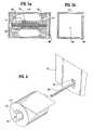
- FIGS. 4 a and 4 bare sectional views of an alternate embodiment.
- FIGS. 5 a and 5 bare sectional views of an alternate embodiment.
- FIG. 6is a perspective view of an alternate embodiment.
- FIG. 1is a pictorial representation of a thermal transfer printer 10 .
- Thermal transfer printer 10includes a thermal print head 12 for printing images on a web 14 , such as a roll of pressure sensitive labels, tickets, or tags, by transferring ink from a transfer ribbon 16 to web 14 at print line 18 .
- Web 14is advanced by a platen 20 , which carries transfer ribbon 16 along with it due to the frictional contact with web 14 at print line 18 under pressure of spring 15 .
- Platen 20is driven by a stepper motor 22 through a belt 24 and a drive pulley 26 .
- After printing a label, ticket, or tag, web 14is advanced to a cutting edge 28 where the label, ticket, or tag can be torn off by the user.
- the torn edge 30is then retracted before printing the next label, ticket, or tag.
- Spent transfer ribbon 32passes from print line 18 via a guide 34 to a takeup core 36 removably positioned on a takeup spindle 38 .
- Takeup spindle 38is driven by belt 24 through a pulley 40 and a clutch (not shown), which limits the takeup torque to avoid breaking the ribbon.
- Transfer ribbon 16is fed from ribbon roll 42 , which is wound on core 44 and contained within a ribbon cartridge 46 , passing around guide 47 to print line 18 .
- Thermal printer 10is adapted to receive and support ribbon cartridge 46 on shelf 48 .
- Cartridge 46includes certain novel features and structural details further illustrated in FIG. 2 and described below.
- cartridge 46includes a carton 47 , preferably formed of cardboard or corrugated fiber-board, which encloses ribbon roll 42 , wound on hollow core 44 , and preferably formed of fiber or alternatively formed of plastic.
- Core 44further encloses brake 48 , formed of an elastomer, preferably urethane. Slots 92 and 94 in facing walls of carton 47 capture the ends of brake 48 and prevent its rotation.
- brake 48includes a clutch section 66 , spring sections 68 and 70 , and end sections 72 and 74 .
- Clutch section 66is dimensioned for an interference fit with core 44 .
- the degree of interference and the durometer and thickness of brake 48are chosen to define a desired drag torque on roll 42 at which core 44 will begin to slip against clutch section 66 .
- brake 48 and the corresponding slots 92 and 94may be, for example, non-rectangular in cross section while remaining within the scope of the invention.
- Spring sections 68 and 70are typically of smaller cross section so as not to interfere with the rotation of core 44 , but rather to twist elastically as indicated in FIG. 3 b , thus permitting clutch section 66 to rotate until the drag torque is reached and clutch section 66 slips continuously against core 44 as ribbon 16 is withdrawn.
- the energy thus stored in spring sections 68 and 70serve to retract slack when ribbon 16 is backfed.
- spring sections 68 and 70may be, for example, notches or slits in brake 48 .
- brake 48is rotated ninety degrees and inserts 58 and 60 , preferably formed of thermoformed plastic, support the weight of roll 42 by means of protrusions 62 and 64 respectively protruding into core 44 .
- inserts 58 and 60include slots 59 and 61 (not shown) to capture the ends of brake 48 .
- Supports 58 and 60may be used in addition to slots in the carton as previously described, or in the alternative.
- a multi-diametral (i.e., having more than one diameter) spring 76has a clutch section 78 having an outer diameter chosen for an interference fit to core 44 and forming a spring clutch structure, and two torsion spring sections 80 and 82 of lesser diameter.
- Spring 76is anchored to holes 84 and 86 (not shown) in inserts 88 and 90 that prevent its overall rotation.
- spring 76may be anchored directly to holes in the facing walls of cartridge 46 in lieu of inserts at the loss of some ease of assembly.
- brake 48further includes axial hole 96 .
- Ribbon roll 42is supported by a passive pin 98 fixed to printer 10 .
- Brake 48is captured and prevented from rotating by slot 99 , also a part of printer 10 .
- brake 48 or the equivalent multi-diametral spring 76is not limited to a single structure to lie within the scope of the invention, and that either may equivalently be comprised of individual parts performing the spring and clutch functions.
- the ribboncan be wound on a core longer than the ribbon width, or the core as described can be fitted to an internal spindle and the clutch functionality coupled to the outside diameter of the core or spindle rather than to the inside diameter. While such embodiments may be more costly to manufacture, it is intended that they fall within the scope of the invention.
- Cartridge 46is intended to be disposable, hence core 44 , and brake 48 or equivalently spring 76 can be dimensioned to provide the drag torque specific to the composition and width of ribbon 16 . This eliminates the ribbon supply torque mechanisms or user adjustments of the prior art thermal printers.
Landscapes
- Impression-Transfer Materials And Handling Thereof (AREA)
- Handling Of Continuous Sheets Of Paper (AREA)
- Printers Characterized By Their Purpose (AREA)
Abstract
Description
Claims (14)
Priority Applications (14)
| Application Number | Priority Date | Filing Date | Title |
|---|---|---|---|
| US10/141,322US6848845B2 (en) | 2002-05-08 | 2002-05-08 | Thermal ribbon cartridge or roll with slack ribbon retraction |
| JP2004503269AJP2005528251A (en) | 2002-05-08 | 2003-01-10 | Thermal ribbon cartridge or roll with loose ribbon contraction |
| PCT/US2003/000731WO2003095214A1 (en) | 2002-05-08 | 2003-01-10 | Thermal ribbon cartridge or roll with slack ribbon retraction |
| BR0311857-6ABR0311857A (en) | 2002-05-08 | 2003-01-10 | Ribbon cartridge, loose peel-off ribbon roll, self-contained clutch action, and printer assembly |
| IL16471503AIL164715A0 (en) | 2002-05-08 | 2003-01-10 | Thermal ribbon cartridge or roll with slack ribbonretraction |
| RU2004135532/12ARU2004135532A (en) | 2002-05-08 | 2003-01-10 | CARTRIDGE OR ROLL OF HEAT TRANSFER TAPES WITH PERFORMANCE OF SAGING TAPE |
| EP03750015AEP1503902A1 (en) | 2002-05-08 | 2003-01-10 | Thermal ribbon cartridge or roll with slack ribbon retraction |
| MXPA04011047AMXPA04011047A (en) | 2002-05-08 | 2003-01-10 | Thermal ribbon cartridge or roll with slack ribbon retraction. |
| AU2003267720AAU2003267720A1 (en) | 2002-05-08 | 2003-01-10 | Thermal ribbon cartridge or roll with slack ribbon retraction |
| KR10-2004-7016589AKR20050006166A (en) | 2002-05-08 | 2003-01-10 | Thermal ribbon cartridge or roll with slack ribbon retraction |
| CA002482539ACA2482539A1 (en) | 2002-05-08 | 2003-01-10 | Thermal ribbon cartridge or roll with slack ribbon retraction |
| CNA038101181ACN1649740A (en) | 2002-05-08 | 2003-01-10 | Thermal ribbon cartridge or roll with slack ribbon retraction |
| US10/736,882US20040141783A1 (en) | 2002-05-08 | 2003-12-16 | Thermal ribbon cartridge or roll with slack ribbon retraction |
| ZA200408823AZA200408823B (en) | 2002-05-08 | 2004-11-01 | Thermal ribbon cartridge or roll with slack ribbonretraction. |
Applications Claiming Priority (1)
| Application Number | Priority Date | Filing Date | Title |
|---|---|---|---|
| US10/141,322US6848845B2 (en) | 2002-05-08 | 2002-05-08 | Thermal ribbon cartridge or roll with slack ribbon retraction |
Related Child Applications (1)
| Application Number | Title | Priority Date | Filing Date |
|---|---|---|---|
| US10/736,882DivisionUS20040141783A1 (en) | 2002-05-08 | 2003-12-16 | Thermal ribbon cartridge or roll with slack ribbon retraction |
Publications (2)
| Publication Number | Publication Date |
|---|---|
| US20030210941A1 US20030210941A1 (en) | 2003-11-13 |
| US6848845B2true US6848845B2 (en) | 2005-02-01 |
Family
ID=29399634
Family Applications (2)
| Application Number | Title | Priority Date | Filing Date |
|---|---|---|---|
| US10/141,322Expired - LifetimeUS6848845B2 (en) | 2002-05-08 | 2002-05-08 | Thermal ribbon cartridge or roll with slack ribbon retraction |
| US10/736,882AbandonedUS20040141783A1 (en) | 2002-05-08 | 2003-12-16 | Thermal ribbon cartridge or roll with slack ribbon retraction |
Family Applications After (1)
| Application Number | Title | Priority Date | Filing Date |
|---|---|---|---|
| US10/736,882AbandonedUS20040141783A1 (en) | 2002-05-08 | 2003-12-16 | Thermal ribbon cartridge or roll with slack ribbon retraction |
Country Status (13)
| Country | Link |
|---|---|
| US (2) | US6848845B2 (en) |
| EP (1) | EP1503902A1 (en) |
| JP (1) | JP2005528251A (en) |
| KR (1) | KR20050006166A (en) |
| CN (1) | CN1649740A (en) |
| AU (1) | AU2003267720A1 (en) |
| BR (1) | BR0311857A (en) |
| CA (1) | CA2482539A1 (en) |
| IL (1) | IL164715A0 (en) |
| MX (1) | MXPA04011047A (en) |
| RU (1) | RU2004135532A (en) |
| WO (1) | WO2003095214A1 (en) |
| ZA (1) | ZA200408823B (en) |
Cited By (3)
| Publication number | Priority date | Publication date | Assignee | Title |
|---|---|---|---|---|
| US20070086823A1 (en)* | 2003-10-20 | 2007-04-19 | Zih Corp. | Replaceable Ribbon Supply and Substrate Cleaning Apparatus |
| US10819869B1 (en) | 2019-07-19 | 2020-10-27 | Zebra Technologies Corporation | Media curl mitigation system |
| US11413893B2 (en) | 2019-06-07 | 2022-08-16 | Zebra Technologies Corporation | Bidirectional printer ribbon supply system |
Families Citing this family (7)
| Publication number | Priority date | Publication date | Assignee | Title |
|---|---|---|---|---|
| US8465220B2 (en) | 2007-12-07 | 2013-06-18 | Dymo, N.V. | Label printing apparatus |
| EP2370262B1 (en)* | 2008-11-10 | 2013-07-24 | Brady Worldwide, Inc. | Cartridge media retention mechanism |
| CN105922779A (en)* | 2016-04-21 | 2016-09-07 | 南京富士通电子信息科技股份有限公司 | Method for preventing wrinkles of color tape of flat-bed printer from causing fed paper blockage |
| JP6931300B2 (en)* | 2017-06-22 | 2021-09-01 | 東芝テック株式会社 | Printers and programs |
| JP7287860B2 (en)* | 2019-03-19 | 2023-06-06 | セイコーエプソン株式会社 | cartridge and tape printers |
| CN109910453B (en)* | 2019-04-01 | 2024-05-10 | 佛山市顺德区高宝实业发展有限公司 | Ribbon rack assembly machine |
| CN115056578A (en)* | 2022-05-20 | 2022-09-16 | 深圳市美松智能设备有限公司 | Thermal transfer printer and printing method |
Citations (20)
| Publication number | Priority date | Publication date | Assignee | Title |
|---|---|---|---|---|
| EP0165396A2 (en) | 1984-04-12 | 1985-12-27 | Hitachi, Ltd. | Ink ribbon cassette for a printer |
| US4625931A (en)* | 1982-08-27 | 1986-12-02 | Kabushiki Kaisha Sato | Web-meandering preventing device |
| US4773775A (en) | 1983-11-04 | 1988-09-27 | Kroy Inc. | Tape-ribbon cartridge |
| US4838716A (en) | 1985-03-04 | 1989-06-13 | Mitsubishi Denki Kabushiki Kaisha | Ribbon cartridge for a printer |
| US4886384A (en) | 1985-01-19 | 1989-12-12 | Francotyp-Postalia Gmbh | Ribbon cassettes |
| US5170956A (en)* | 1991-03-04 | 1992-12-15 | Mctaggart Willam R | Dispenser for rolled sheet material |
| US5284396A (en) | 1991-07-29 | 1994-02-08 | Kanzaki Paper Mfg. Co., Ltd. | Ribbon feeder for a printer having a tension mechanism |
| US5297750A (en)* | 1992-12-16 | 1994-03-29 | Hunt Jack E | Holder for rolls of material |
| US5297879A (en) | 1992-04-27 | 1994-03-29 | Kabushiki Kaisha Sato | Mechanism for preventing slack in printer carbon ribbon |
| EP0408356B1 (en) | 1989-07-14 | 1994-06-22 | Tokyo Electric Co., Ltd. | Thermal printer and ink ribbon arrangement therefor |
| US5443319A (en)* | 1986-07-15 | 1995-08-22 | Monarch Marking Systems, Inc. | Ink ribbon cartridge installation and methods relating thereto |
| US5595447A (en) | 1992-10-13 | 1997-01-21 | Seiko Epson Corporation | Tape cartridge and printing device having print medium cartridge |
| US5772341A (en)* | 1993-10-15 | 1998-06-30 | Monarch Marking Systems, Inc. | Ink ribbon cartridge |
| US5938350A (en)* | 1997-06-19 | 1999-08-17 | Datamax Corporation | Thermal ink printer with ink ribbon supply |
| US6130699A (en) | 1997-07-03 | 2000-10-10 | Datamax Corporation | Thermal ink printer with media supply |
| US6129463A (en) | 1997-11-24 | 2000-10-10 | Datamax Corporation | Ribbon tensioning assembly |
| US6142686A (en)* | 1998-03-02 | 2000-11-07 | Brady Worldwide | Method and apparatus for maintaining ribbon tension |
| USRE36953E (en)* | 1995-09-22 | 2000-11-14 | Eltron International, Inc. | Computer driven printer |
| US6231253B1 (en) | 1997-10-31 | 2001-05-15 | Zih Corporation | Label printer with a peel bar, a separator bar and anti-buckle means |
| US6307583B1 (en) | 1999-09-01 | 2001-10-23 | Illinois Tool Works Inc. | Thermal printer with reversible ribbon and method therefor |
Family Cites Families (7)
| Publication number | Priority date | Publication date | Assignee | Title |
|---|---|---|---|---|
| KR960003354B1 (en)* | 1986-04-24 | 1996-03-08 | 타우러스 임프레션스 인코오포레이티드 | Book cover serial stamp printer |
| US4886364A (en)* | 1987-04-06 | 1989-12-12 | Kearfott Guidance & Navigation Corporation | Ring laser gyroscope beam combiner for separating and combining circulating laser beams for power and fringe pattern detections |
| US5087137A (en)* | 1988-07-19 | 1992-02-11 | Datamax Corporation | Ribbon assembly including indicia to identify operating parameters and ribbon depletion |
| US5035325A (en)* | 1989-07-18 | 1991-07-30 | Dai Nippon Insatsu Kabushiki Kaisha | Cassette for thermal transfer printing film |
| US5719616A (en)* | 1995-01-23 | 1998-02-17 | Dai Nippon Printing Co., Ltd. | Thermal transfer film cassette and thermal transfer recording method |
| US5620544A (en)* | 1995-06-07 | 1997-04-15 | Minnesota Mining And Manufacturing Company | Tape roll liner/tab, application apparatus and method |
| JP3827204B2 (en)* | 2000-12-19 | 2006-09-27 | 富士写真フイルム株式会社 | Photosensitive material magazine |
- 2002
- 2002-05-08USUS10/141,322patent/US6848845B2/ennot_activeExpired - Lifetime
- 2003
- 2003-01-10CNCNA038101181Apatent/CN1649740A/enactivePending
- 2003-01-10WOPCT/US2003/000731patent/WO2003095214A1/ennot_activeApplication Discontinuation
- 2003-01-10AUAU2003267720Apatent/AU2003267720A1/ennot_activeAbandoned
- 2003-01-10EPEP03750015Apatent/EP1503902A1/ennot_activeWithdrawn
- 2003-01-10JPJP2004503269Apatent/JP2005528251A/enactivePending
- 2003-01-10KRKR10-2004-7016589Apatent/KR20050006166A/ennot_activeWithdrawn
- 2003-01-10CACA002482539Apatent/CA2482539A1/ennot_activeAbandoned
- 2003-01-10RURU2004135532/12Apatent/RU2004135532A/ennot_activeApplication Discontinuation
- 2003-01-10ILIL16471503Apatent/IL164715A0/enunknown
- 2003-01-10BRBR0311857-6Apatent/BR0311857A/ennot_activeApplication Discontinuation
- 2003-01-10MXMXPA04011047Apatent/MXPA04011047A/enunknown
- 2003-12-16USUS10/736,882patent/US20040141783A1/ennot_activeAbandoned
- 2004
- 2004-11-01ZAZA200408823Apatent/ZA200408823B/enunknown
Patent Citations (22)
| Publication number | Priority date | Publication date | Assignee | Title |
|---|---|---|---|---|
| US4625931A (en)* | 1982-08-27 | 1986-12-02 | Kabushiki Kaisha Sato | Web-meandering preventing device |
| US4773775A (en) | 1983-11-04 | 1988-09-27 | Kroy Inc. | Tape-ribbon cartridge |
| EP0165396A2 (en) | 1984-04-12 | 1985-12-27 | Hitachi, Ltd. | Ink ribbon cassette for a printer |
| US4886384A (en) | 1985-01-19 | 1989-12-12 | Francotyp-Postalia Gmbh | Ribbon cassettes |
| US4838716A (en) | 1985-03-04 | 1989-06-13 | Mitsubishi Denki Kabushiki Kaisha | Ribbon cartridge for a printer |
| US5443319A (en)* | 1986-07-15 | 1995-08-22 | Monarch Marking Systems, Inc. | Ink ribbon cartridge installation and methods relating thereto |
| EP0408356B1 (en) | 1989-07-14 | 1994-06-22 | Tokyo Electric Co., Ltd. | Thermal printer and ink ribbon arrangement therefor |
| US5170956A (en)* | 1991-03-04 | 1992-12-15 | Mctaggart Willam R | Dispenser for rolled sheet material |
| US5284396A (en) | 1991-07-29 | 1994-02-08 | Kanzaki Paper Mfg. Co., Ltd. | Ribbon feeder for a printer having a tension mechanism |
| US5297879A (en) | 1992-04-27 | 1994-03-29 | Kabushiki Kaisha Sato | Mechanism for preventing slack in printer carbon ribbon |
| US5595447A (en) | 1992-10-13 | 1997-01-21 | Seiko Epson Corporation | Tape cartridge and printing device having print medium cartridge |
| US5788387A (en) | 1992-10-13 | 1998-08-04 | Meisei International Patent Firm | Tape cartidge and printing device |
| US6126344A (en) | 1992-10-13 | 2000-10-03 | Seiko Epson Corporation | Tape cartridge and printing device |
| US5297750A (en)* | 1992-12-16 | 1994-03-29 | Hunt Jack E | Holder for rolls of material |
| US5772341A (en)* | 1993-10-15 | 1998-06-30 | Monarch Marking Systems, Inc. | Ink ribbon cartridge |
| USRE36953E (en)* | 1995-09-22 | 2000-11-14 | Eltron International, Inc. | Computer driven printer |
| US5938350A (en)* | 1997-06-19 | 1999-08-17 | Datamax Corporation | Thermal ink printer with ink ribbon supply |
| US6130699A (en) | 1997-07-03 | 2000-10-10 | Datamax Corporation | Thermal ink printer with media supply |
| US6231253B1 (en) | 1997-10-31 | 2001-05-15 | Zih Corporation | Label printer with a peel bar, a separator bar and anti-buckle means |
| US6129463A (en) | 1997-11-24 | 2000-10-10 | Datamax Corporation | Ribbon tensioning assembly |
| US6142686A (en)* | 1998-03-02 | 2000-11-07 | Brady Worldwide | Method and apparatus for maintaining ribbon tension |
| US6307583B1 (en) | 1999-09-01 | 2001-10-23 | Illinois Tool Works Inc. | Thermal printer with reversible ribbon and method therefor |
Non-Patent Citations (1)
| Title |
|---|
| Internal Solutions for Wed Designers and Builders Professional-Structuring XML Documents by Richard V. Dragan, Article from Website http://www.pcmag.com. |
Cited By (5)
| Publication number | Priority date | Publication date | Assignee | Title |
|---|---|---|---|---|
| US20070086823A1 (en)* | 2003-10-20 | 2007-04-19 | Zih Corp. | Replaceable Ribbon Supply and Substrate Cleaning Apparatus |
| US7934881B2 (en) | 2003-10-20 | 2011-05-03 | Zih Corp. | Replaceable ribbon supply and substrate cleaning apparatus |
| US11413893B2 (en) | 2019-06-07 | 2022-08-16 | Zebra Technologies Corporation | Bidirectional printer ribbon supply system |
| US12208634B2 (en) | 2019-06-07 | 2025-01-28 | Zebra Technologies Corporation | Bidirectional printer ribbon supply system |
| US10819869B1 (en) | 2019-07-19 | 2020-10-27 | Zebra Technologies Corporation | Media curl mitigation system |
Also Published As
| Publication number | Publication date |
|---|---|
| RU2004135532A (en) | 2005-07-20 |
| MXPA04011047A (en) | 2005-02-14 |
| US20040141783A1 (en) | 2004-07-22 |
| EP1503902A1 (en) | 2005-02-09 |
| WO2003095214A1 (en) | 2003-11-20 |
| US20030210941A1 (en) | 2003-11-13 |
| BR0311857A (en) | 2005-04-26 |
| CA2482539A1 (en) | 2003-11-20 |
| CN1649740A (en) | 2005-08-03 |
| JP2005528251A (en) | 2005-09-22 |
| AU2003267720A1 (en) | 2003-11-11 |
| KR20050006166A (en) | 2005-01-15 |
| IL164715A0 (en) | 2005-12-18 |
| ZA200408823B (en) | 2005-11-15 |
Similar Documents
| Publication | Publication Date | Title |
|---|---|---|
| KR101532396B1 (en) | Printer with printhead assembly, clutch assembly, and printer ribbon transport assembly | |
| US6848845B2 (en) | Thermal ribbon cartridge or roll with slack ribbon retraction | |
| JP2007502221A (en) | Printer with pivot gear mechanism | |
| JP2008265180A (en) | Tape cartridge and tape printer | |
| EP0408356B1 (en) | Thermal printer and ink ribbon arrangement therefor | |
| GB2033340A (en) | Web cartridges | |
| JPH01235678A (en) | Thermal transfer recorder | |
| JP4933234B2 (en) | Printing apparatus and printing method | |
| JP3164154B2 (en) | Cassette for thermal transfer printer | |
| US5051011A (en) | Thermal printer with shutter ribbon end detector | |
| JP4538059B2 (en) | Ribbon feeder | |
| JP3031450B2 (en) | Printing cassette | |
| JP5607971B2 (en) | Printer for ink ribbon cassette and printer for ink ribbon cassette | |
| RU2201873C1 (en) | Method of printing using heat-transfer printer and heat- transfer printer for implementing the method | |
| US6290408B1 (en) | Ribbon cassette with friction mechanism | |
| JPH0443518B2 (en) | ||
| JPS60204559A (en) | Device for appropriately sending out belt material | |
| JP2004262499A (en) | Label printer | |
| JPH0839908A (en) | Printing cassette | |
| JP3033283B2 (en) | Thermal transfer recording apparatus and ink paper loading method thereof | |
| JPS6350126Y2 (en) | ||
| JP4346727B2 (en) | Ink ribbon support device | |
| JPS59185687A (en) | printing device | |
| JP2000177222A (en) | Ribbon refill mechanism for printing device | |
| JPH02279380A (en) | Manual printer |
Legal Events
| Date | Code | Title | Description |
|---|---|---|---|
| AS | Assignment | Owner name:ZEBRA INVESTMENT HOLDING CORPORATION, DELAWARE Free format text:ASSIGNMENT OF ASSIGNORS INTEREST;ASSIGNOR:POOLE, DAVID L.;REEL/FRAME:013021/0126 Effective date:20020610 | |
| AS | Assignment | Owner name:ZIH CORP., DELAWARE Free format text:ASSIGNMENT OF ASSIGNORS INTEREST;ASSIGNOR:POOLE, DAVID L.;REEL/FRAME:013534/0079 Effective date:20021107 | |
| FEPP | Fee payment procedure | Free format text:PAYOR NUMBER ASSIGNED (ORIGINAL EVENT CODE: ASPN); ENTITY STATUS OF PATENT OWNER: LARGE ENTITY | |
| STCF | Information on status: patent grant | Free format text:PATENTED CASE | |
| AS | Assignment | Owner name:ZIH CORP., BERMUDA Free format text:CORRECTIVE COVERSHEET TO CORRECT THE ADDRESS OF THE ASSIGNEE THAT WAS PREVIOUSLY RECORDED ON REEL 013534, FRAME 0079.;ASSIGNOR:POOLE, DAVID L.;REEL/FRAME:016835/0590 Effective date:20021107 | |
| FPAY | Fee payment | Year of fee payment:4 | |
| FPAY | Fee payment | Year of fee payment:8 | |
| AS | Assignment | Owner name:ZIH CORP., DELAWARE Free format text:CORRECTIVE ASSIGNMENT TO CORRECT THE ASSIGNEE NAME PREVIOUSLY RECORDED ON REEL 013021 FRAME 0126. ASSIGNOR(S) HEREBY CONFIRMS THE ASSIGNEE NAME IS "ZIH CORP." AND THE CONVEYANCE TYPE AT REEL/FRAME 013534/0079 SHOULD BE "CORRECTIVE ASSIGNMENT";ASSIGNOR:POOLE, DAVID L.;REEL/FRAME:033087/0488 Effective date:20021107 | |
| AS | Assignment | Owner name:MORGAN STANLEY SENIOR FUNDING, INC. AS THE COLLATERAL AGENT, MARYLAND Free format text:SECURITY AGREEMENT;ASSIGNORS:ZIH CORP.;LASER BAND, LLC;ZEBRA ENTERPRISE SOLUTIONS CORP.;AND OTHERS;REEL/FRAME:034114/0270 Effective date:20141027 Owner name:MORGAN STANLEY SENIOR FUNDING, INC. AS THE COLLATE Free format text:SECURITY AGREEMENT;ASSIGNORS:ZIH CORP.;LASER BAND, LLC;ZEBRA ENTERPRISE SOLUTIONS CORP.;AND OTHERS;REEL/FRAME:034114/0270 Effective date:20141027 | |
| FPAY | Fee payment | Year of fee payment:12 | |
| AS | Assignment | Owner name:JPMORGAN CHASE BANK, N.A., AS THE SUCCESSOR AGENT, NEW YORK Free format text:PATENT SECURITY INTEREST ASSIGNMENT AGREEMENT;ASSIGNOR:MORGAN STANLEY SENIOR FUNDING, INC., AS THE EXISTING AGENT;REEL/FRAME:044791/0842 Effective date:20170907 Owner name:JPMORGAN CHASE BANK, N.A., AS THE SUCCESSOR AGENT, Free format text:PATENT SECURITY INTEREST ASSIGNMENT AGREEMENT;ASSIGNOR:MORGAN STANLEY SENIOR FUNDING, INC., AS THE EXISTING AGENT;REEL/FRAME:044791/0842 Effective date:20170907 | |
| AS | Assignment | Owner name:ZEBRA TECHNOLOGIES CORPORATION, ILLINOIS Free format text:MERGER;ASSIGNOR:ZIH CORP.;REEL/FRAME:048884/0618 Effective date:20181220 | |
| AS | Assignment | Owner name:JPMORGAN CHASE BANK, N.A., AS COLLATERAL AGENT, NE Free format text:NOTICE OF TRANSFER OF SECURITY INTEREST IN PATENTS;ASSIGNOR:ZEBRA TECHNOLOGIES CORPORATION;REEL/FRAME:049675/0049 Effective date:20190701 Owner name:JPMORGAN CHASE BANK, N.A., AS COLLATERAL AGENT, NEW YORK Free format text:NOTICE OF TRANSFER OF SECURITY INTEREST IN PATENTS;ASSIGNOR:ZEBRA TECHNOLOGIES CORPORATION;REEL/FRAME:049675/0049 Effective date:20190701 | |
| AS | Assignment | Owner name:JPMORGAN CHASE BANK, N.A., NEW YORK Free format text:SECURITY INTEREST;ASSIGNORS:ZEBRA TECHNOLOGIES CORPORATION;LASER BAND, LLC;TEMPTIME CORPORATION;REEL/FRAME:053841/0212 Effective date:20200901 | |
| AS | Assignment | Owner name:ZEBRA TECHNOLOGIES CORPORATION, ILLINOIS Free format text:RELEASE OF SECURITY INTEREST - 364 - DAY;ASSIGNOR:JPMORGAN CHASE BANK, N.A.;REEL/FRAME:056036/0590 Effective date:20210225 Owner name:TEMPTIME CORPORATION, NEW JERSEY Free format text:RELEASE OF SECURITY INTEREST - 364 - DAY;ASSIGNOR:JPMORGAN CHASE BANK, N.A.;REEL/FRAME:056036/0590 Effective date:20210225 Owner name:LASER BAND, LLC, ILLINOIS Free format text:RELEASE OF SECURITY INTEREST - 364 - DAY;ASSIGNOR:JPMORGAN CHASE BANK, N.A.;REEL/FRAME:056036/0590 Effective date:20210225 |