US6846588B2 - Hollow inorganic membranes produced by metal or composite electrodeposition - Google Patents
Hollow inorganic membranes produced by metal or composite electrodepositionDownload PDFInfo
- Publication number
- US6846588B2 US6846588B2US10/053,241US5324102AUS6846588B2US 6846588 B2US6846588 B2US 6846588B2US 5324102 AUS5324102 AUS 5324102AUS 6846588 B2US6846588 B2US 6846588B2
- Authority
- US
- United States
- Prior art keywords
- electrode
- metal
- core
- membrane
- ceramic
- Prior art date
- Legal status (The legal status is an assumption and is not a legal conclusion. Google has not performed a legal analysis and makes no representation as to the accuracy of the status listed.)
- Expired - Lifetime, expires
Links
Images


Classifications
- H—ELECTRICITY
- H01—ELECTRIC ELEMENTS
- H01M—PROCESSES OR MEANS, e.g. BATTERIES, FOR THE DIRECT CONVERSION OF CHEMICAL ENERGY INTO ELECTRICAL ENERGY
- H01M4/00—Electrodes
- H01M4/86—Inert electrodes with catalytic activity, e.g. for fuel cells
- H01M4/88—Processes of manufacture
- C—CHEMISTRY; METALLURGY
- C25—ELECTROLYTIC OR ELECTROPHORETIC PROCESSES; APPARATUS THEREFOR
- C25D—PROCESSES FOR THE ELECTROLYTIC OR ELECTROPHORETIC PRODUCTION OF COATINGS; ELECTROFORMING; APPARATUS THEREFOR
- C25D13/00—Electrophoretic coating characterised by the process
- C25D13/02—Electrophoretic coating characterised by the process with inorganic material
- C—CHEMISTRY; METALLURGY
- C04—CEMENTS; CONCRETE; ARTIFICIAL STONE; CERAMICS; REFRACTORIES
- C04B—LIME, MAGNESIA; SLAG; CEMENTS; COMPOSITIONS THEREOF, e.g. MORTARS, CONCRETE OR LIKE BUILDING MATERIALS; ARTIFICIAL STONE; CERAMICS; REFRACTORIES; TREATMENT OF NATURAL STONE
- C04B38/00—Porous mortars, concrete, artificial stone or ceramic ware; Preparation thereof
- C04B38/06—Porous mortars, concrete, artificial stone or ceramic ware; Preparation thereof by burning-out added substances by burning natural expanding materials or by sublimating or melting out added substances
- C—CHEMISTRY; METALLURGY
- C25—ELECTROLYTIC OR ELECTROPHORETIC PROCESSES; APPARATUS THEREFOR
- C25D—PROCESSES FOR THE ELECTROLYTIC OR ELECTROPHORETIC PRODUCTION OF COATINGS; ELECTROFORMING; APPARATUS THEREFOR
- C25D1/00—Electroforming
- C25D1/12—Electroforming by electrophoresis
- C25D1/14—Electroforming by electrophoresis of inorganic material
- C—CHEMISTRY; METALLURGY
- C25—ELECTROLYTIC OR ELECTROPHORETIC PROCESSES; APPARATUS THEREFOR
- C25D—PROCESSES FOR THE ELECTROLYTIC OR ELECTROPHORETIC PRODUCTION OF COATINGS; ELECTROFORMING; APPARATUS THEREFOR
- C25D13/00—Electrophoretic coating characterised by the process
- C25D13/12—Electrophoretic coating characterised by the process characterised by the article coated
- C25D13/14—Tubes; Rings; Hollow bodies
- H—ELECTRICITY
- H01—ELECTRIC ELEMENTS
- H01M—PROCESSES OR MEANS, e.g. BATTERIES, FOR THE DIRECT CONVERSION OF CHEMICAL ENERGY INTO ELECTRICAL ENERGY
- H01M8/00—Fuel cells; Manufacture thereof
- H01M8/06—Combination of fuel cells with means for production of reactants or for treatment of residues
- H01M8/0606—Combination of fuel cells with means for production of reactants or for treatment of residues with means for production of gaseous reactants
- H01M8/0612—Combination of fuel cells with means for production of reactants or for treatment of residues with means for production of gaseous reactants from carbon-containing material
- H—ELECTRICITY
- H01—ELECTRIC ELEMENTS
- H01M—PROCESSES OR MEANS, e.g. BATTERIES, FOR THE DIRECT CONVERSION OF CHEMICAL ENERGY INTO ELECTRICAL ENERGY
- H01M8/00—Fuel cells; Manufacture thereof
- H01M8/10—Fuel cells with solid electrolytes
- H01M8/12—Fuel cells with solid electrolytes operating at high temperature, e.g. with stabilised ZrO2 electrolyte
- H01M8/1213—Fuel cells with solid electrolytes operating at high temperature, e.g. with stabilised ZrO2 electrolyte characterised by the electrode/electrolyte combination or the supporting material
- H01M8/1226—Fuel cells with solid electrolytes operating at high temperature, e.g. with stabilised ZrO2 electrolyte characterised by the electrode/electrolyte combination or the supporting material characterised by the supporting layer
- H—ELECTRICITY
- H01—ELECTRIC ELEMENTS
- H01M—PROCESSES OR MEANS, e.g. BATTERIES, FOR THE DIRECT CONVERSION OF CHEMICAL ENERGY INTO ELECTRICAL ENERGY
- H01M8/00—Fuel cells; Manufacture thereof
- H01M8/24—Grouping of fuel cells, e.g. stacking of fuel cells
- H01M8/2465—Details of groupings of fuel cells
- H01M8/247—Arrangements for tightening a stack, for accommodation of a stack in a tank or for assembling different tanks
- H01M8/2475—Enclosures, casings or containers of fuel cell stacks
- H—ELECTRICITY
- H01—ELECTRIC ELEMENTS
- H01M—PROCESSES OR MEANS, e.g. BATTERIES, FOR THE DIRECT CONVERSION OF CHEMICAL ENERGY INTO ELECTRICAL ENERGY
- H01M8/00—Fuel cells; Manufacture thereof
- H01M8/24—Grouping of fuel cells, e.g. stacking of fuel cells
- H01M8/2465—Details of groupings of fuel cells
- H01M8/2484—Details of groupings of fuel cells characterised by external manifolds
- H01M8/2485—Arrangements for sealing external manifolds; Arrangements for mounting external manifolds around a stack
- C—CHEMISTRY; METALLURGY
- C04—CEMENTS; CONCRETE; ARTIFICIAL STONE; CERAMICS; REFRACTORIES
- C04B—LIME, MAGNESIA; SLAG; CEMENTS; COMPOSITIONS THEREOF, e.g. MORTARS, CONCRETE OR LIKE BUILDING MATERIALS; ARTIFICIAL STONE; CERAMICS; REFRACTORIES; TREATMENT OF NATURAL STONE
- C04B2111/00—Mortars, concrete or artificial stone or mixtures to prepare them, characterised by specific function, property or use
- C04B2111/00474—Uses not provided for elsewhere in C04B2111/00
- C04B2111/00853—Uses not provided for elsewhere in C04B2111/00 in electrochemical cells or batteries, e.g. fuel cells
- Y—GENERAL TAGGING OF NEW TECHNOLOGICAL DEVELOPMENTS; GENERAL TAGGING OF CROSS-SECTIONAL TECHNOLOGIES SPANNING OVER SEVERAL SECTIONS OF THE IPC; TECHNICAL SUBJECTS COVERED BY FORMER USPC CROSS-REFERENCE ART COLLECTIONS [XRACs] AND DIGESTS
- Y02—TECHNOLOGIES OR APPLICATIONS FOR MITIGATION OR ADAPTATION AGAINST CLIMATE CHANGE
- Y02E—REDUCTION OF GREENHOUSE GAS [GHG] EMISSIONS, RELATED TO ENERGY GENERATION, TRANSMISSION OR DISTRIBUTION
- Y02E60/00—Enabling technologies; Technologies with a potential or indirect contribution to GHG emissions mitigation
- Y02E60/30—Hydrogen technology
- Y02E60/50—Fuel cells
Definitions
- This inventionrelates generally to the production of hollow inorganic membranes produced by metal or composite electrodeposition, and in particular to hollow inorganic laminated composite membranes produced by such methods and that are particularly useful in solid oxide fuel cell applications.
- EPDelectrophoretic deposition
- electrophoretic depositionIt is well known to deposit coatings of material on a conductive core by electrophoretic deposition (EPD).
- EPDis a combination of electrophoresis and deposition. Electrophoresis is the movement of charged particles in an electric field. Deposition is the coagulation of particles into a mass.
- Applicant's own PCT application no. PCT/CA01/00634relates generally to the production of hollow ceramic membranes by EPD, and in particular to the production of hollow ceramic electrodes by EPD for solid oxide fuel cells (SOFC).
- SOFCsolid oxide fuel cells
- a SOFCcomprises two electrodes (anode and cathode) separated by a ceramic, solid-phase electrolyte.
- the SOFCoperates at an elevated temperature, typically in the order of about 1000° C.
- the material in typical SOFC electrolytesis a fully dense (i.e. non-porous) yttria-stabilized zirconia (YSZ) which is an excellent conductor of negatively charged oxygen (oxide) ions at high temperatures.
- Typical SOFC anodesare made from a porous nickel/zirconia cermet while typical cathodes are made from magnesium doped lanthanum manganate (LaMnO 3 ), or a strontium doped lanthanum manganate (also known as lanthanum strontium manganate (LSM)).
- LaMnO 3magnesium doped lanthanum manganate
- LSMstrontium doped lanthanum manganate
- hydrogen or carbon monoxide (CO) in a fuel stream passing over the anodereacts with oxide ions conducted through the electrolyte to produce water and/or CO 2 and electrons.
- COcarbon monoxide
- the electronspass from the anode to outside the fuel cell via an external circuit, through a load on the circuit, and back to the cathode where oxygen from an air stream receives the electrons and is converted into oxide ions which are injected into the electrolyte.
- SOFC reactionsinclude:
- Known SOFC designsinclude planar and tubular fuel cells.
- Applicant's own PCT application no. PCT/CA01/00634discloses a method of producing a tubular electrode supported electrochemical fuel cell by
- the inner electrodemay be the anode
- the outer electrodemay be the cathode.
- fuelmay be supplied to the anode by passing through the tube, and air may be supplied to the cathode by passing over the outer surface of the tube.
- a method of producing a porous hollow inorganic electrode for a solid oxide fuel cellcomprising
- the ceramic particlesmay be co-deposited with the metal on the core by electrodeposition to form a single-layered electrode.
- the metal and some combustible particlesmay first be electrodeposited on the core to form a metal layer, then the ceramic particles and some combustible particles are deposited onto the metal layer by one of electrodeposition or electrophoretic deposition, thereby forming a dual-layered electrode.
- the methodmay further comprise prior to deposition, applying a masking material onto the combustible core, and after deposition, removing the masking material, thereby leaving an electrode structure that has openings that correspond to the masked areas; these openings allow the passage of reactant through the electrode.
- the coremay be made of a flexible material, such that after electrodepositing and before sintering, the electrode can be manipulated into a suitable electrode shape.
- the shapesmay include one or a combination of shapes from the group of U-shaped, serpentine-shaped, or coiled shaped.
- the metal of the electrodemay be chosen from the group of nickel, copper, palladium, chromium, platinum, gold silver and/or their alloys.
- the coremay be chose from the group of a carbon fibre, a carbon fibre bundle, a carbon tow, or a carbon rod.
- the combustible particlesmay be chosen from the group consisting of carbon, carbon black, and organic and polymeric compounds.
- the porosity of the electrodemay be controlled by one or more of controlling the duration and temperature of the sintering step, controlling the particle size, size distribution and/or surface area of the combustible particles, controlling the thickness of the electrode, or controlling the sintering atmosphere.
- a method of producing a hollow solid oxide fuel cellthat includes the method of producing the electrode as described above. After the electrode has dried, and before it is sintered, a ceramic electrolyte membrane is attached to the outside surface of the electrode by electrophoretically depositing ceramic particles onto the electrode. These ceramic particles may be yittria-stabilized zirconia.
- an outer electrode layeris attached to the outer surface of the electrolyte.
- the electrophoretic deposition stepmay be repeated before sintering to form the outer electrode layer on the electrolyte.
- the ceramic particulate material for the outer electrodemay be different or have different characteristics than the electrolyte.
- the outer particulate materialmay include combustible particles, that create a porous outer electrode after sintering. If the composition of the ceramic material of the electrolyte and outer electrode are the same, one or more of the particle size, distribution, surface area, microstructure and porosity can be different.
- a method of producing a hollow inorganic membranecomprises
- the inorganic materialmay also include ceramic particles that are co-deposited with the metal on the core by electrodeposition, thereby producing a hollow inorganic cermet membrane.
- the materialmay also include combustible particles, such that upon sintering the membrane the combustible particles also comubst, thereby producing a hollow porous inorganic membrane. Such a membrane may be useful in fluid separation applications.
- ceramic particlesmay be electrophoretically deposited onto the metallic membrane, thereby forming a multi-membrane hollow structure having an inner metal-containing membrane, and an outer ceramic membrane.
- an outer ceramic membranemay be useful as a support structure for a thin inner metallic membrane used in gas separation applications.
- Combustible particlesmay be electrophoretically co-deposited with the ceramic particles onto the metallic membrane. Then, the multi-membrane structure may be sintered so that the electrophoretically deposited combustible particles can also combust, thereby producing a multi-membrane structure having a porous inner and outer membrane.
- the coremay be of a flexible material, and the method may further comprising after electrodepositing and before sintering, manipulating the membrane into a desired shape.
- the electrodemay be manipulated into one or a combination of shapes from the group of U-shaped, serpentine-shaped, or coiled shaped.
- the metalmay be chosen from the group of nickel, copper, palladium, chromium, platinum, gold silver and/or their alloys.
- An inner membrane made of thin palladium layermay be particularly useful in hydrogen gas separation applications.
- the ceramic particlesmay be from the group of be yittria-stabilized zirconia.
- the coremay be chosen from the group of a carbon fibre, a carbon fibre bundle, a carbon tow, or a carbon rod.
- the combustible particlesmay be chosen from the group consisting of carbon, carbon black, and organic and polymeric compounds.
- the membrane porositymay be controlled by one or more of controlling the duration and temperature of the sintering step, controlling the sintering atmosphere, controlling the particle size, size distribution and/or surface area of the combustable particles, or controlling the thickness of the membrane.
- a hollow inorganic multi-layered membrane apparatus, and a hollow solid oxide fuel cellmay be produced by one or more of the above methods.
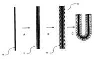
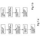
- FIG. 1is a flowchart of the steps for producing an inner electrode of a tubular SOFC; in particular, FIG. 1 ( a ) illustrates the production of a dual-layered electrode structure, and FIG. 1 ( b ) illustrates the production of a single-layered electrode structure.
- FIG. 2is a schematic illustration of the method of producing a dual-layered electrode as shown in the flowchart of FIG. 1 ( a ).
- FIG. 3is a schematic illustration of the method of producing a single-layered electrode structure as shown in the flowchart of FIG. 1 ( b ).
- FIG. 4is a flowchart of a method of producing an electrolyte by EPD on the electrode of FIGS. 1 ( a ) or 1 ( b ).
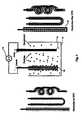
- FIG. 5is a schematic illustration of an EPD apparatus used to produce the electrolyte shown in FIG. 4 .
- FIGS. 6 ( a ) and 6 ( b )are schematic illustrations of forming openings in a fuel cell electrode by applying masking strips over a conductive core.
- a method of producing a HIM made of either metal or cermetwherein the metal membrane is produced by metal electrodeposition (MED) on a flexible conductive core, and the cermet membrane by composite electrodeposition (CED) also on a flexible conductive core, and wherein the HIM produced by either method is ductile enough to be manipulated into a suitable shape.
- MEDmetal electrodeposition
- CEDcomposite electrodeposition
- the present inventionalso provides a method of producing a HICLM having at least one of the HIMs produced according to above aspect of the invention.
- a HICLM for SOFC applicationsmay have a porous inner HIM that serves as an electrode, a non-porous middle HIM that serves as an electrolyte, and a porous outer membrane that serves as an electrode, wherein the inner HIM is manufactured by one or more of MED and CED.
- a method of manufacturing a HICLM for use as a solid oxide fuel cell(SOFC).
- SOFChas three membranes: an inner electrode membrane, a middle electrolyte membrane, and an outer electrode membrane.
- the electrodesserve as a current collector and a catalyst.
- the electrolyteallows oxygen ions to pass from one electrode (cathode) to the other (anode), and is impermeable to nitrogen in air and fuel gas flows on either side of the electrolyte.
- the first stage in producing the SOFCis to produce an inner electrode 10 .
- the inner electrode 10may be produced as a two-layered structure (FIGS. 1 ( a ) and 2 ) or a single-layered structure (FIGS. 1 ( b ) and 3 ).
- an electrically conductive metal layer 12is first deposited by metal electrodeposition (MED) onto a conductive core 14 .
- an ionically conductive ceramic-containing layer 16is deposited over the metal layer 12 by electrophoretic deposition (EPD), or by composite electrodeposition (CED).
- ELDelectrophoretic deposition
- CEDcomposite electrodeposition
- the anode 10is formed by depositing an electrically and ionically conductive cermet layer 18 onto the conductive core 14 by CED.
- MEDis a process of depositing a metal onto a conductive core by electrolysis.
- the conductive coreis commonly referred to as an “electrode” in the electrodeposition art.
- the conductive core electrode 10will herein be referred to as the “deposition electrode”.
- the MED processrequires two deposition electrodes 14 (anode and cathode), an electrolyte bath (i.e. metal salt solution), and a source of electrons.
- the electrons “e”may be supplied by an external DC current source that is connected via an external circuit to the deposition anode and cathode.
- metal ions M n ⁇ ⁇ M n+travel through the bath from the deposition anode and deposit on the deposition cathode, and electrons travel via the circuit from the deposition anode to the deposition cathode.
- An MED apparatus(not shown) is provided for carrying out the MED process.
- the apparatusincludes a container for holding a metal salt solution, a deposition anode in the container having a metal to be deposited, a deposition cathode in the container for receiving the deposited metal, an external DC electric current source, and, an external circuit electrically connected to the deposition anode, the deposition cathode, and the external current source.
- the inner electrode 10may serve as anode or cathode; in this embodiment, the inner electrode 10 is the anode.
- a suitable anode metalis deposited by MED on the deposition cathode 14 (step A in FIG. 2 ); such suitable metal may be nickel.
- Other suitable metalsinclude copper, palladium, chromium, platinum, gold, silver and/or their alloys.
- the inner electrode 10preferably comprises one of platinum, gold, silver and/or their alloys.
- the metal salt solutionmay suitably be Krohn Bright Nickel Electrolyte Solution by Krohn Technical Products, Carlstadt N.J. 07072.
- Nickelis a particularly suitable choice for use in the anode, as it is relatively cheap, is effective as an electron conductor and as a catalyst for the anode, and helps to break down natural gas fuel into hydrogen atoms and carbon monoxide.
- an ionically conductive ceramic-containing materialis then deposited onto the nickel layer (step B in FIG. 2 ).
- a layer of nickel/zirconium oxide cermetmay be deposited over the nickel layer by CED or EPD, to form a dual-layered anode structure.
- the cermet layeris deposited by CED, as the cermet tends to adhere to the core in a way that allows for easy manipulation.
- cermet deposited by EPDtends to break or flake away from the core if manipulated; in such case, the core bearing the metal layer may be manipulated prior to the deposition of cermet by EPD.
- the dual-layered anode structurehas a thickness of between 1 ⁇ m to 200 ⁇ m.
- the CED processis similar to the MED process except that the electrolyte bath contains ceramic particles in addition to metal.
- the aforementioned Krohn plating solutionmay also serve as a suitable such electrolyte bath.
- metal and ceramic particlesdeposit simultaneously forming a cermet coating. Cermet particles are deposited on a deposition cathode on application of a DC electric field (continuous or pulse DC field) from an external current source.
- the cermet membranehas electron and ion conductive and catalytic properties.
- the anode 10may comprise a single layer 18 that is both electrically and ionically conductive.
- a layer 18may be formed by CED of cermet particles directly on the deposition electrode 14 (step A in FIG. 3 ).
- the electrode 10can be made porous by adding to the electrolyte bath combustable additives such as carbon, carbon black, graphite powder, corn starch, and rice starch. As discussed in more detail below, a sintering process is applied to the electrode 10 that causes the combustible materials to burn away, leaving behind pores in the electrode 10 .
- the electrolyte bath combustable additivessuch as carbon, carbon black, graphite powder, corn starch, and rice starch.
- the anode 10is porous and is deposited around the deposition electrode 14 such that it completely surrounds the deposition electrode 14 .
- non-conductive masking material 20may be placed on the deposition electrode prior to MED, such that when the anode materials are deposited, they are deposited only on the portions of the deposition electrode 14 not covered by the masking material 20 .
- an anode 10is formed having openings 22 (where the masking material used to be) that allow access of reactant to the electrolyte.
- the masking material 20may be in the form of spaced parallel strips 24 .
- the masking material 20may take the form of a rectangular mesh 26 ; after the mesh 26 is removed, an anode 10 is formed having a pattern of rectangles 28 corresponding to the openings of the mesh 26 . It is evident that the masking material 20 may be arranged in a number of other shapes.
- the strips 24may comprise a plurality of squares (not shown) such that when the strips are removed, an anode is formed having a mesh-like pattern.
- the electrode 10can be formed on a number of different combustable, electrically conductive cores including a carbon fibre 14 or carbon tow (not shown) or a carbon rod (not shown).
- the carbon fibre 14may have a diameter of approximately 5 microns or less and may be suitable to produce very fine HIMs.
- fibre tow having a diameter of about 5 or 6 mmmay be used to produce larger HIMs.
- rods having a desired diametermay be used in place of fibre tow 10 .
- the rodsmay have any suitable cross-sectional configuration.
- Fibre towmay be used either treated with a polymeric binder or untreated.
- a treated fibre corewill produce a ceramic tube having substantially a single hole.
- a fibre core made from untreated fibre towmay result in a tube having a plurality of holes in a porous core.
- the fibre towmay be treated by briefly dipping the tow into a solution of an organic or polymeric binder.
- a solution of nitrocellulose in acetoneis suitable.
- the nitrocelluloseforms a very thin coating on the tow and seals the interfilamentous gaps.
- the bindershould preferably be insoluble in the EPD medium. Nitrocellulose is a preferred binder because it is insoluble in ethanol, which is a preferred EPD medium.
- the deposited particlesmay infiltrate the tow during the deposition process, resulting in the porous core referred to above.
- the porous coremay be preferred in some applications in which a high internal surface area may be beneficial. Examples of such application include high surface area catalyst supports or membrane reactors.
- the electrode 10is disconnected from the electroplating apparatus external circuit and removed from the electrolyte bath. Then, if desired, it is manipulated into a suitable shape (step C in FIGS. 2 and 3 ). Both nickel and cermet layers are ductile (provided the cermet was deposited by CED), and enable the electrode to be manipulated into a number of complex shapes without cracking. Also, carbon fibre and untreated fibre tow are flexible and can be manipulated into various shapes without breaking. If the fibre tow is treated with an organic binder, the manipulation should be made before the binder dries, since after drying, the binder will harden and become inflexible.
- a solventcan be applied to the binder to soften it.
- a polymer binderis used, manipulation may be made even after drying, as the polymer binder has a glass transition temperature (T g ) lower than room temperature and does not tend to harden after drying.
- T gglass transition temperature
- a thermoplastic bindermay be used, which hardens after drying, but can be made flexible by application of heat.
- the electrode 10can be manipulated into shapes that are particularly suitable for its intended application. For example, in SOFC applications, it is desirable to maximize the active surface area of the fuel cell in a given volume. Shapes that provide a high surface area per volume include coiled or serpentine shapes (see FIG. 5 ). Also, a fuel cell that has its reactant inlet and outlets at the same end may be advantageous: because a SOFC system operates at a very high temperature, the fuel cells must be effectively thermally insulated from other components in the system, and thus may be located inside a thermally insulated enclosure.
- the fuel cellscan be shaped so that the inlets and outlets of the fuel cell pass through the same opening in the thermally insulated enclosure.
- the electrodemay be bent into a “U” shape so that a U-shaped fuel cell can be produced.
- a coiled or serpentine shaped fuel cellmay also be formed such that the reactant inlets and outlets are at the same end.
- the electrode 10is washed with water to rinse off any electrolyte bath solution, and dried (either at ambient or at an elevated temperature). Then, a ceramic electrolyte layer 30 is deposited by EPD onto the outside surface of the electrode 10 .
- EPDgenerally speaking is a process whereby particles are deposited from a colloid suspension onto a conductive core (deposition electrode) of an opposite charge, upon application of an external DC electrical field.
- the particlesinclude metals, glass, ceramics, polymers or carbon. The application of the electric field causes the migration of particles toward a specific deposition electrode.
- Particles in a colloidare known to develop a surface charge relative to the suspension medium, which may be dependent on the pH of the suspension medium.
- aluminahas a positive charge at a pH of below about 7.
- the ceramic particlesmay be positively or negatively charged; in case of positively charged particles they are deposited on the deposition cathode; in case of negatively charged particles , they are deposited on the deposition anode. It is not essential for the deposition process that the particles have to reach the oppositely charged deposition electrode; particles can be deposited around a deposition electrode onto a semi-permeable membrane which allow ions to pass but not the particles themselves.
- the EPD processis used to deposit a ceramic electrolyte layer 30 onto the electrode 10 according to the following steps:
- the electrolyte/electrode assembly 40After the electrolyte/electrode assembly 40 has dried, it is sintered at a temperature sufficient to burn out the combustible conductive core 14 as well as any combustible additives in the membranes.
- the sinteringalso enables the electrolyte 30 to achieve full density while maintaining the porosity of the inner electrode 10 .
- the sintering cycle for a zirconia deposit where the sintering atmosphere is airmay begin by raising the temperature to about 500° C. to about 900° C. at a heating rate of between 20° C./hr to 300° C./hr and preferably over a period of about 6 hours to about 9 hours and held that temperature for about 3 hours. The temperature may then be raised at a rate of about 100° C.
- the temperaturemay then be lowered at a rate of about 100° C. to about 300° C. per hour to room temperature.
- the powderserves to distribute the heat evenly in all directions to the sample that is placed in the powder-containing plate.
- a suitable such powder for zirconia-based samplesis coarse zirconia (if the powder completely sinters during the sample sintering temperature, it is difficult to recover the sample from the powder; however, a powder that partially sinters may be acceptable if the powder can be readily broken away from the sample after sintering).
- an outer electrode layer(not shown) is formed by any suitable means, including but not restricted to EPDing electrode material onto the electrolyte 30 , or dip-coating, brushing, spraying or sol-gel coating the electrolyte 30 in a electrode slurry (not shown).
- the slurrymay suitably be composed of LSM (or a Mg-doped lanthanum manganate), binder, and solvent and combustible particles.
- the outer electrode compositionmay suitably be LSM, or a LSM/zirconia mixture, or another electrically and ionically conductive ceramic material.
- the outer electrodeis subjected to a drying stage wherein the electrode is subjected to heat at increasing temperatures of 40° C., 60° C., 80° C., 100° C., 120° C., and 140° C.
- the outer electrodemay be heated at each temperature for a period between 10 minutes to 5 hours.
- a final sintering stageis applied to partially density the outer electrode layer, to bond the outer electrode layer to the electrolyte 40 , and to combust any combustible particles in the outer electrode material.
- the sintering cycle where the sintering atmosphere is airmay begin by raising the temperature from room temperature to a first temperature of about 200-250° C., then to a second temperature between about 400-600° C., then to a third temperature between about 800-900° C., then finally to a temperature of between 1200 to 1300° C.
- the heating rate for each of these sintering stepsis between about 20-200° C./hr.
- the electrodeis held at each of these temperatures for between about 15 minutes to 5 hours.
- the temperaturemay then be lowered at a rate of about 60-300° C. per hour to room temperature.
- the inner electrode diametercan be selected by selecting a particular diameter of the core.
- the ductility of the inner electrodecan be controlled by controlling the amount of additives (generally, the greater the amount of second phase additives, the less ductile the electrode).
- Porosity of the electrodes 10can be controlled by controlling the quantity and type of combustible particles added to the ceramic particle suspension.
- combustible particlescan include carbon black, carbon, graphite, different polymer powders and cellulose base powders.
- the combustible particlesare co-deposited onto the conductive core during MED or CED.
- the electrodesare heated during sintering, the combustible particles are burned off (along with the core), leaving a porous hollow structure.
- the porositycan also be controlled by controlling the temperature and time of the sintering process. Long sintering times or sintering at higher temperatures or a combination of both can reduce porosity. Porosity can also be controlled by controlling the ceramic particle size distribution and its surface area. Finer and high surface area ceramic particles normally will have a lower porosity than coarse and low surface area powder when both of them are sintered under identical conditions. Porosity can also be controlled by sintering additives which are well known in the art, such as glassy or sol-get phase or any other liquid forming phases. The time and temperature parameters in a typical sintering cycle, may be varied by one skilled in the art to achieve a particular desired result.
- a tubular SOFCis produced according the steps in the above method along with an additional sintering step that occurs after the inner electrode is deposited on the conductive core, but before the electrolyte is deposited onto the inner electrode.
- a method of producing a tubular SOFCis provided having three sintering cycles. In the first cycle, and after the inner electrode is formed, the core bearing the inner electrode is subjected to the first sintering cycle, wherein the temperature is raised from room temperature to about 500 C. at a heating rate of about 30-100° C./hr and held at that temperature for between about 10 minutes to 3 hours. Then the temperature is raised at a rate of about 60-200° C./hr to 900° C.
- the temperatureis raised at a rate of between about 100-300° C./ hr to 1100-1300 C. and held there for between about 1 to 5 hours.
- the combustible core and combustible particles (if any)combust, leaving behind a hollow (and porous if combustible particles in the electrode material are present) electrode structure .
- the electrodeis cooled at a rate of 100-300° C./hr to room temperature.
- zirconia electrolyteis deposited onto the electrode by EPD or by vacuum casting, and the electrode/electrolyte structure is subjected to the second sintering cycle.
- the structureis heated from room temp to 900° C. at a rate of between about 60-200° C./hr, then without holding at that temperature to between about 1300-1500° C. (preferably at 1400° C.) at a rate of between about 200-300° C./hr and held at that temperature for between about 1-5 hours. Then, the structure is cooled at 300° C. per hour to room temperature. Then, ceramic material is applied onto the electrolyte to form the outer electrode by painting, dip coating etc. and the fuel cell structure is subjected to the third sintering cycle.
- the structureis heated from room temperature to a first temperature of about 200-250° C., then to a second temperature between about 400-600° C., then to a third temperature between about 800-900° C., then finally to a temperature of between 1200 to 1300° C.
- the heating rate for each of these sintering stepsis between about 20-200° C./hr.
- the electrodeis sintered at each of these temperatures for between about 15 minutes to 5 hours. The temperature may then be lowered at a rate of about 60-300° C. per hour to room temperature.
- HIM or HICLM structures according to the inventionhave other applications, including:
- a HICLMis provided having a metal (or cermet) inner membrane and a ceramic outer membrane in adjacent contact. Both metal (or cermet) and ceramic membranes are porous, i.e. there are pores extending through the radial (thickness) dimension of the membrane. The porosity of each membrane can be selected depending on the type of separation required; smaller pores may be required to separate liquids having smaller molecular sizes from other liquids or solids.
- This HICLMis suitable for fresh water treatment, waste water treatment, waste oil treatment, gas separation, and biotechnology/pharmaceutical-related purification and concentration applications.
- a HICLMhaving a thin non-porous Pd or Pd-alloy metal (or cermet) inner membrane, and a porous ceramic outer membrane.
- This HICLMis useful for hydrogen gas separation applications since hydrogen gas is diffusible through the Pd or Pd-alloy.
- the Pd or Pd-alloy inner membraneis kept thin to minimize costs and reduce hydrogen diffusion time; the outer membrane thus acts as a support substrate for the metal membrane.
- the HICLMmay be provided with a porous Pd or Pd-alloy metal (or cermet) inner membrane and a dense ceramic outer membrane that is non-porous, and that is an ionic or mixed conductor.
- the metal layerserves as an electrode and catalyst.
- the properties of the electrolyteare selected so that the electrolyte is impermeable to certain gases, but will allow certain ions to pass therethrough.
- the ceramicis made from stabilized zirconia
- the HICLMcan separate oxygen from air by separating oxygen molecules into electrons and oxygen ions at the inner membrane upon application of electric current from an external DC source, then pass the oxygen ions through the electrolyte, for recombining with the electrons that have traveled from the inner membrane to the outside surface of the electrolyte through an external circuit.
Landscapes
- Chemical & Material Sciences (AREA)
- Engineering & Computer Science (AREA)
- Chemical Kinetics & Catalysis (AREA)
- Electrochemistry (AREA)
- Life Sciences & Earth Sciences (AREA)
- Organic Chemistry (AREA)
- General Chemical & Material Sciences (AREA)
- Manufacturing & Machinery (AREA)
- Materials Engineering (AREA)
- Sustainable Development (AREA)
- Sustainable Energy (AREA)
- Metallurgy (AREA)
- Inorganic Chemistry (AREA)
- Ceramic Engineering (AREA)
- Molecular Biology (AREA)
- Health & Medical Sciences (AREA)
- Structural Engineering (AREA)
- Inert Electrodes (AREA)
- Fuel Cell (AREA)
Abstract
Description
- H2+O=→H2O+2e−
- CO+O=→CO2+2e−
- CH4+4O=→2H2O+CO2+8e−
- O2+4e−→2O=
- (a) electrophoretically depositing an anodic or cathodic material onto a fibre core to create a porous electrode layer;
- (b) depositing a solid electrolyte layer onto the electrode layer;
- (c) drying and sintering the core bearing the deposited material or cathode layer and the solid electrolyte layer at a temperature and for a length of time sufficient to combust the fibre core and to create a fully dense electrolyte layer while maintaining the porosity of the inner electrode layer;
- (d) depositing an outer electrode layer onto the solid electrolyte layer, which is of an anodic material if the inner layer comprises a cathodic material, or a cathodic material if the inner layer comprises a anodic material;
- (e) sintering the end product at a temperature and for a length of time sufficient to bond the outer layer to the solid electrolyte layer while maintaining the porosity of the outer and inner electrode layers.
- (a) depositing electrode material onto an electrically conductive combustible core, the electrode material including electrically conductive metal, ionically conductive ceramic particles, and combustible particles, wherein at least the metal is deposited by electrodeposition;
- (b) drying the core bearing the deposited electrode material; then,
- (c) sintering the core bearing the deposited electrode material such that the core and combustible particles combust, thereby producing a porous hollow inorganic electrode.
- (a) electrodepositing an inorganic material that includes electrically conductive metal onto an electrically conductive combustible core;
- (b) drying the core bearing the deposited inorganic material; then,
- (c) sintering the core bearing the deposited inorganic material such that the core combusts, thereby producing a hollow inorganic metal-containing membrane.
- The term “fibre” or “filament” refers to a single strand of fibrous material; “fibre tow” or “fibre bundle” shall refer to a multi-filament yarn or an array of fibres; and “fibre core” shall refer to a fibre, filament, fibre tow or fibre bundle. In all cases, the fibre core is electrically conductive or treated to be electrically conductive to allow its use as an electrode.
- The term “ceramic” refers to inorganic non-metallic solid materials with a prevalent covalent or ionic bond including, but not limited to metallic oxides (such as oxides of aluminum, silicon, magnesium, zirconium, titanium, chromium, lanthanum, hafnium, yttrium and mixtures thereof) and nonoxide compounds including but not limited to carbides (such as of titanium tungsten, boron, silicon), silicides (such as molybdenum disicilicide), nitrides (such as of boron, aluminum, titanium, silicon) and borides (such as of tungsten, titanium, uranium) and mixtures thereof; spinels, titanates (such as barium titanate, lead titanate, lead zirconium titanates, strontium titanate, iron titanate), ceramic super conductors, zeolites, and ceramic solid ionic conductors (such as yittria stabilized zirconia, beta-alumina and cerates).
- The term “cermet” refers to a composite material comprising a ceramic in combination with a metal, typically but not necessarily a sintered metal, and typically exhibiting a high resistance to temperature, corrosion, and abrasion.
- The term “hollow inorganic membrane (HIM)” refers to a tubular body comprising an inorganic material. The cross-sectional geometry may be any shape such as circular, square, rectangular, triangular, and polygonal. The longitudinal geometry of the tubular body may be any shape such as elongate, serpentine, and coiled. The membrane may be porous or non-porous. The inorganic material includes metal, cermet composite, and ceramic.
- The term “hollow inorganic composite laminated membranes (HICLM)” refers to an assembly of multiple concentric contacting layers of hollow inorganic membranes, wherein one or more membrane layers may have different material compositions.
- The term “porous” in the context of hollow ceramic, metal, and cermet membranes means that the ceramic material contains pores (voids). Therefore, the density of the porous membrane material is lower than that of the theoretical density of the material. The voids in the porous membranes can be connected (i.e., channel type) or disconnected (i.e. isolated). In a porous hollow membrane, the majority of the pores are connected. To be considered porous as used herein in reference to membranes, a membrane should have a density which is at most about 95% of the theoretical density of the material. The amount of porosity can be determined by measuring the bulk density of the porous body and from the theoretical density of the materials in the porous body. Pore size and its distribution in a porous body can be measured by mercury or non-mercury porosimeters, BET or microstructural image analysis as is well known in the art.
- (a) prepare a EPD suspension comprising a selected ratio of ceramic powder, solvent and grinding media, by grinding and mixing these materials together until the average particle size reaches an appropriate size range. In one embodiment the particle size range may range from 150 nm to about 10,000 nm. The particles should preferably be no larger than 15,000 nm. More preferably, the particle size range may be between 200 nm to 1000 nm. As will be appreciated by those skilled in the art, larger particle sizes may result in the ceramic membrane having greater porosity than a ceramic membrane having a smaller particle size in identical sintering conditions (e.g. temperature, time, atmosphere);
- (b) Add additional solvent to get the desired concentration; the solvent may a non-aqueous organic fluid such as ethanol, isopropanol, butanol, butylamine, acetylacetone, methyl ethyl ketone, acetone, methanol, absolute alcohol or mixtures thereof; suitable concentrations include 0.25 vol % to 30 vol % of particles in the suspension;
- (c) Add additives to stabilize the suspension, e.g. acetic acid;
- (d) Transfer the suspension to an EPD cell as shown in
FIG. 5 ; the EPD cell includescontainer 32, adeposition anode 34, a deposition cathode36 and an external DCelectrical source 38; - (e) Place the
electrode 10 in the suspension, and electrically connect it to thedeposition anode 34; when so connected, theelectrode 10 serves as the deposition cathode in the EPD process; - (f) Turn on the DC
electrical source 38 to activate the EPD process; continue until theelectrode 10 is coated with ceramic material30 of a desired thickness between the range of 1 μm to 1000 μm; - (g) Disconnect and remove the electrolyte/electrode assembly40 from the circuit, and remove it from the EPD cell; and,
- (h) Dry the electrolyte/electrode assembly40 in preparation for sintering; drying may take place at room temperature or at a slightly elevated temperature.
Claims (45)
Priority Applications (12)
| Application Number | Priority Date | Filing Date | Title |
|---|---|---|---|
| US10/053,241US6846588B2 (en) | 2002-01-16 | 2002-01-16 | Hollow inorganic membranes produced by metal or composite electrodeposition |
| US10/078,548US6824907B2 (en) | 2002-01-16 | 2002-02-14 | Tubular solid oxide fuel cell stack |
| US10/156,755US6936367B2 (en) | 2002-01-16 | 2002-05-23 | Solid oxide fuel cell system |
| US10/207,668US6893762B2 (en) | 2002-01-16 | 2002-07-25 | Metal-supported tubular micro-fuel cell |
| KR10-2004-7011066AKR20040081131A (en) | 2002-01-16 | 2003-01-16 | Hollow Inorganic Membranes Produced by Metal or Composite Electodeposition |
| CA2472778ACA2472778C (en) | 2002-01-16 | 2003-01-16 | Hollow inorganic membranes produced by metal or composite electrodeposition |
| PCT/CA2003/000059WO2003062503A1 (en) | 2002-01-16 | 2003-01-16 | Hollow inorganic membranes produced by metal or composite electrodeposition |
| EP03731643AEP1466040A1 (en) | 2002-01-16 | 2003-01-16 | Hollow inorganic membranes produced by metal or composite electrodeposition |
| JP2003562363AJP2005515610A (en) | 2002-01-16 | 2003-01-16 | Hollow inorganic membrane produced by electrodeposition method of metal or composite material |
| RU2004125150/02ARU2004125150A (en) | 2002-01-16 | 2003-01-16 | HOLLOW INORGANIC MEMBRANES OBTAINED BY ELECTRODEPOSITION OF METAL OR COMPOSITE MATERIAL |
| CNA038045869ACN1639391A (en) | 2002-01-16 | 2003-01-16 | Hollow inorganic membranes produced by metal or composite electrodeposition |
| US10/522,235US7452622B2 (en) | 2002-01-16 | 2003-07-24 | Metal-supported tubular fuel cell |
Applications Claiming Priority (1)
| Application Number | Priority Date | Filing Date | Title |
|---|---|---|---|
| US10/053,241US6846588B2 (en) | 2002-01-16 | 2002-01-16 | Hollow inorganic membranes produced by metal or composite electrodeposition |
Related Parent Applications (1)
| Application Number | Title | Priority Date | Filing Date |
|---|---|---|---|
| US10/078,548Continuation-In-PartUS6824907B2 (en) | 2002-01-16 | 2002-02-14 | Tubular solid oxide fuel cell stack |
Related Child Applications (3)
| Application Number | Title | Priority Date | Filing Date |
|---|---|---|---|
| US10/078,548Continuation-In-PartUS6824907B2 (en) | 2002-01-16 | 2002-02-14 | Tubular solid oxide fuel cell stack |
| US10/156,755Continuation-In-PartUS6936367B2 (en) | 2002-01-16 | 2002-05-23 | Solid oxide fuel cell system |
| US10/207,668Continuation-In-PartUS6893762B2 (en) | 2002-01-16 | 2002-07-25 | Metal-supported tubular micro-fuel cell |
Publications (2)
| Publication Number | Publication Date |
|---|---|
| US20030134176A1 US20030134176A1 (en) | 2003-07-17 |
| US6846588B2true US6846588B2 (en) | 2005-01-25 |
Family
ID=21982850
Family Applications (1)
| Application Number | Title | Priority Date | Filing Date |
|---|---|---|---|
| US10/053,241Expired - LifetimeUS6846588B2 (en) | 2002-01-16 | 2002-01-16 | Hollow inorganic membranes produced by metal or composite electrodeposition |
Country Status (8)
| Country | Link |
|---|---|
| US (1) | US6846588B2 (en) |
| EP (1) | EP1466040A1 (en) |
| JP (1) | JP2005515610A (en) |
| KR (1) | KR20040081131A (en) |
| CN (1) | CN1639391A (en) |
| CA (1) | CA2472778C (en) |
| RU (1) | RU2004125150A (en) |
| WO (1) | WO2003062503A1 (en) |
Cited By (6)
| Publication number | Priority date | Publication date | Assignee | Title |
|---|---|---|---|---|
| US20040137286A1 (en)* | 2003-01-15 | 2004-07-15 | Gregory Hilmas | Solid oxide fuel cell and method for preparing the same |
| US20060051643A1 (en)* | 2002-01-16 | 2006-03-09 | Alberta Research Council Inc. | Metal-supported tubular fuel cell |
| US20070228273A1 (en)* | 2006-03-31 | 2007-10-04 | Mingui Sun | Portable apparatus that delivers power and information to implantable devices |
| US20080318071A1 (en)* | 2007-06-21 | 2008-12-25 | Moen Incorporated | Metallic coating on substrate |
| US20090155660A1 (en)* | 2007-12-14 | 2009-06-18 | Korea Institute Of Energy Research | Tubular solid oxide fuel cells |
| US8182668B1 (en) | 2008-07-29 | 2012-05-22 | Technion Research And Development Foundation Ltd. | Method for producing a barium titanate layer by cathodic electrophoretic deposition from aqueous solution |
Families Citing this family (29)
| Publication number | Priority date | Publication date | Assignee | Title |
|---|---|---|---|---|
| US6824907B2 (en)* | 2002-01-16 | 2004-11-30 | Alberta Reasearch Council, Inc. | Tubular solid oxide fuel cell stack |
| US7736772B2 (en)* | 2002-02-14 | 2010-06-15 | Alberta Research Council, Inc. | Tubular solid oxide fuel cell stack |
| US6844100B2 (en)* | 2002-08-27 | 2005-01-18 | General Electric Company | Fuel cell stack and fuel cell module |
| US7758992B2 (en)* | 2002-11-15 | 2010-07-20 | Battelle Memorial Institute | Copper-substituted perovskite compositions for solid oxide fuel cell cathodes and oxygen reduction electrodes in other electrochemical devices |
| CA2414622A1 (en) | 2002-12-17 | 2004-06-17 | Alberta Research Council Inc. | Compact solid oxide fuel cell stack |
| CA2452938A1 (en) | 2003-12-15 | 2005-06-15 | Alberta Research Council Inc. | Heat exchanger for solid oxide fuel cell stack |
| CA2457609A1 (en) | 2004-02-13 | 2005-08-13 | Alberta Research Council Inc. | Heating solid oxide fuel cell stack |
| US7335432B2 (en) | 2004-04-30 | 2008-02-26 | Motorola, Inc. | Solid oxide fuel cell portable power source |
| WO2006044313A2 (en)* | 2004-10-12 | 2006-04-27 | The Trustrees Of The University Of Pennsylvania | Preparation of solid oxide fuel cell electrodes by electrodeposition |
| JP4687406B2 (en)* | 2005-11-10 | 2011-05-25 | トヨタ自動車株式会社 | Fuel cell |
| JP4915045B2 (en)* | 2005-02-04 | 2012-04-11 | トヨタ自動車株式会社 | Membrane electrode composite for tube fuel cell and tube fuel cell |
| CA2587705C (en)* | 2005-02-04 | 2010-09-28 | Toyota Jidosha Kabushiki Kaisha | Hollow-type fuel cell having hollow-shaped membrane electrode assembly |
| US8709674B2 (en)* | 2005-04-29 | 2014-04-29 | Alberta Research Council Inc. | Fuel cell support structure |
| JP2006344486A (en)* | 2005-06-08 | 2006-12-21 | Japan Fine Ceramics Center | Solid oxide fuel cell and method for producing the same |
| KR100818383B1 (en)* | 2005-08-05 | 2008-04-01 | 마이티테크, 인코퍼레이티드. | Method for manufacturing nanostructured composite electrode by electrophoretic electrodeposition and product manufactured by the method |
| JP4817230B2 (en)* | 2005-10-20 | 2011-11-16 | 独立行政法人産業技術総合研究所 | Electrochemical microcoil reactor and electrochemical reaction system comprising the same |
| WO2008038293A2 (en)* | 2006-09-27 | 2008-04-03 | Yissum Research Development Company Of The Hebrew University Of Jerusalem | Electrochemical co-deposition of sol-gel films |
| JP4999436B2 (en)* | 2006-12-01 | 2012-08-15 | 新光電気工業株式会社 | Direct flame fuel cell |
| KR100918472B1 (en) | 2007-07-23 | 2009-09-24 | 삼성전기주식회사 | Supercapacitor electrode and manufacturing method thereof |
| KR100974001B1 (en) | 2008-04-08 | 2010-08-05 | 한국에너지기술연구원 | Manufacturing method of acid resistant ceramic separator using electrophoresis method and ceramic separator prepared therefrom |
| US20100116733A1 (en)* | 2008-11-12 | 2010-05-13 | Korea Electrotechnology Research Institute | Nanoporous oxide ceramic membranes of tubular and hollow fiber shape and method of making the same |
| WO2010061854A1 (en)* | 2008-11-26 | 2010-06-03 | 国立大学法人横浜国立大学 | System for degrading and removing toxic substance by means of thermal excitation of chromium oxide or nickel oxide |
| CN101787556B (en)* | 2009-01-23 | 2012-02-01 | 中国科学院海洋研究所 | an electrolytic cell |
| FR2982083B1 (en)* | 2011-11-02 | 2014-06-27 | Fabien Gaben | METHOD FOR PRODUCING SOLID ELECTROLYTE THIN FILMS FOR LITHIUM ION BATTERIES |
| KR101462798B1 (en)* | 2013-07-16 | 2014-11-20 | 삼성전기주식회사 | Conductive paste composition for external electrode and multilayer ceramic components using the same |
| RU2586371C1 (en)* | 2014-12-03 | 2016-06-10 | Федеральное государственное бюджетное образовательное учреждение высшего профессионального образования "Российский химико-технологический университет имени Д. И. Менделеева (РХТУ им. Д. И. Менделеева) | Method for electrodeposition of nickel-based composite coatings and nano-sized zirconium dioxide |
| US10457001B2 (en)* | 2017-04-13 | 2019-10-29 | Infineon Technologies Ag | Method for forming a matrix composite layer and workpiece with a matrix composite layer |
| FR3080957B1 (en) | 2018-05-07 | 2020-07-10 | I-Ten | MESOPOROUS ELECTRODES FOR THIN FILM ELECTROCHEMICAL DEVICES |
| CN116024619B (en)* | 2022-11-25 | 2024-11-15 | 梧州三和新材料科技有限公司 | Porous metal with open framework and method of making same |
Citations (65)
| Publication number | Priority date | Publication date | Assignee | Title |
|---|---|---|---|---|
| US3707234A (en) | 1971-05-04 | 1972-12-26 | Westinghouse Electric Corp | Support module for reverse osmosis membrane |
| US4454207A (en) | 1983-07-13 | 1984-06-12 | The United States Of America As Represented By The United States Department Of Energy | Steam reforming of fuel to hydrogen in fuel cells |
| US4490444A (en) | 1980-12-22 | 1984-12-25 | Westinghouse Electric Corp. | High temperature solid electrolyte fuel cell configurations and interconnections |
| US4567117A (en) | 1982-07-08 | 1986-01-28 | Energy Research Corporation | Fuel cell employing non-uniform catalyst |
| US4728584A (en) | 1986-10-21 | 1988-03-01 | Westinghouse Electric Corp. | Fuel cell generator containing self-supporting high gas flow solid oxide electrolyte fuel cells |
| US4729931A (en) | 1986-11-03 | 1988-03-08 | Westinghouse Electric Corp. | Reforming of fuel inside fuel cell generator |
| US4791035A (en) | 1987-12-10 | 1988-12-13 | Westinghouse Electric Corp. | Cell and current collector felt arrangement for solid oxide electrochemical cell combinations |
| DE3922673A1 (en) | 1989-07-10 | 1991-01-24 | Siemens Ag | HIGH TEMPERATURE FUEL CELL |
| US5002647A (en) | 1988-07-21 | 1991-03-26 | Mitsubishi Metal Corporation | Process for preparation of thick films by electrophoresis |
| EP0424673A1 (en) | 1989-09-26 | 1991-05-02 | Asea Brown Boveri Aktiengesellschaft | Process for the production of a shaped ceramic product |
| EP0451971A1 (en) | 1990-03-26 | 1991-10-16 | Ngk Insulators, Ltd. | Solid oxide fuel cells |
| US5077148A (en) | 1989-05-03 | 1991-12-31 | Institute Of Gas Technology | Fully internal manifolded and internal reformed fuel cell stack |
| US5103871A (en) | 1988-12-22 | 1992-04-14 | Ngk Insulators, Ltd. | One-end closed ceramic double tube and method of manufacturing the same |
| JPH04237964A (en) | 1991-01-21 | 1992-08-26 | Toto Ltd | Fuel cell |
| JPH04248272A (en) | 1991-01-09 | 1992-09-03 | Central Res Inst Of Electric Power Ind | Manufacture of interconnector of lateral-striped cylindrical solid electrolyte fuel cell |
| US5169731A (en) | 1990-04-24 | 1992-12-08 | Yoshida Kogyo K.K. | Solid oxide fuel cell and method for manufacturing the same |
| US5190834A (en)* | 1990-10-24 | 1993-03-02 | Imperial Chemical Industries Plc | Composite membrarnes and electrochemical cells containing them |
| US5244752A (en) | 1991-12-06 | 1993-09-14 | Westinghouse Electric Corp. | Apparatus tube configuration and mounting for solid oxide fuel cells |
| US5273837A (en) | 1992-12-23 | 1993-12-28 | Corning Incorporated | Solid electrolyte fuel cells |
| US5302319A (en) | 1991-01-07 | 1994-04-12 | United Technologies Corporation | Preparation of sol gel composition for electrophoresis |
| US5342704A (en) | 1992-04-29 | 1994-08-30 | Westinghouse Electric Corporation | Method of making an air electrode material having controlled sinterability |
| US5380600A (en) | 1989-06-19 | 1995-01-10 | Haldor Topsoe A/S | Fuel cell system |
| US5385700A (en)* | 1991-05-03 | 1995-01-31 | Programme 3 Patent Holdings | Method of making a holder of ceramic material |
| US5458989A (en) | 1992-08-21 | 1995-10-17 | Dodge; Cleveland E. | Tubular fuel cells with structural current collectors |
| EP0678597A1 (en) | 1991-01-07 | 1995-10-25 | United Technologies Corporation | Electrophoresis process for preparation of ceramic fibers |
| US5518827A (en) | 1993-04-28 | 1996-05-21 | Mitsubishi Denki Kabushiki Kaisha | Internal reforming type fuel cell device and fuel cell generating system |
| EP0713931A2 (en) | 1994-11-24 | 1996-05-29 | Nkk Corporation | Method of manufacturing thin zirconia films by electrophoretic deposition |
| JPH09283161A (en)* | 1996-04-15 | 1997-10-31 | Fujikura Ltd | Method for manufacturing cylindrical solid oxide fuel cell |
| US5693230A (en) | 1996-01-25 | 1997-12-02 | Gas Research Institute | Hollow fiber contactor and process |
| US5763114A (en) | 1994-09-01 | 1998-06-09 | Gas Research Institute | Integrated reformer/CPN SOFC stack module design |
| JPH10158894A (en) | 1996-11-29 | 1998-06-16 | Fujikura Ltd | Method for depositing solid electrolyte |
| US5807642A (en) | 1995-11-20 | 1998-09-15 | Xue; Liang An | Solid oxide fuel cell stacks with barium and strontium ceramic bodies |
| US5827620A (en) | 1993-03-20 | 1998-10-27 | Keele University | Solid oxide fuel cell structures |
| EP0896378A1 (en) | 1997-08-08 | 1999-02-10 | Mitsubishi Heavy Industries, Ltd. | Solid electrolyte type fuel battery |
| WO1999017390A1 (en) | 1997-10-01 | 1999-04-08 | Waikatolink Limited | Integrated solid oxide fuel cell and reformer |
| US5895573A (en) | 1996-10-07 | 1999-04-20 | Prime Water Systems N.V. | Ultrafiltration device for domestic/drinking water purification |
| US5908713A (en) | 1997-09-22 | 1999-06-01 | Siemens Westinghouse Power Corporation | Sintered electrode for solid oxide fuel cells |
| US5935727A (en) | 1997-04-10 | 1999-08-10 | The Dow Chemical Company | Solid oxide fuel cells |
| US5942348A (en) | 1994-12-01 | 1999-08-24 | Siemens Aktiengesellschaft | Fuel cell with ceramic-coated bipolar plates and a process for producing the fuel cell |
| JPH11226370A (en) | 1998-02-17 | 1999-08-24 | Nok Corp | Porous ceramic type hollow fiber membrane module |
| US5952116A (en) | 1995-02-16 | 1999-09-14 | Siemens Aktiengesellschaft | Solid electrolyte high temperature fuel cell module and method for its operation |
| US5976721A (en) | 1997-09-15 | 1999-11-02 | Limaye; Santosh Y. | Chemical cogeneration process |
| US5993989A (en) | 1997-04-07 | 1999-11-30 | Siemens Westinghouse Power Corporation | Interfacial material for solid oxide fuel cell |
| US5993985A (en) | 1998-04-09 | 1999-11-30 | Siemens Westinghouse Power Corporation | Fuel cell tubes and method of making same |
| US6001501A (en) | 1998-02-03 | 1999-12-14 | Siemens Westinghouse Power Corporation | Connections for solid oxide fuel cells |
| US6007932A (en) | 1996-10-16 | 1999-12-28 | Gore Enterprise Holdings, Inc. | Tubular fuel cell assembly and method of manufacture |
| US6017646A (en) | 1998-06-03 | 2000-01-25 | Praxair Technology, Inc. | Process integrating a solid oxide fuel cell and an ion transport reactor |
| US6051330A (en) | 1998-01-15 | 2000-04-18 | International Business Machines Corporation | Solid oxide fuel cell having vias and a composite interconnect |
| US6051173A (en) | 1998-01-15 | 2000-04-18 | International Business Machines Corporation | Method of making a solid oxide fuel cell with controlled porosity |
| US6074771A (en) | 1998-02-06 | 2000-06-13 | Igr Enterprises, Inc. | Ceramic composite electrolytic device and method for manufacture thereof |
| US6093297A (en) | 1996-04-02 | 2000-07-25 | Nkk Corporation | Method for depositing solid electrolyte layer |
| US6099985A (en) | 1997-07-03 | 2000-08-08 | Gas Research Institute | SOFC anode for enhanced performance stability and method for manufacturing same |
| US6183897B1 (en) | 1998-09-16 | 2001-02-06 | Sofco | Via filled interconnect for solid oxide fuel cells |
| US6214490B1 (en) | 1998-12-17 | 2001-04-10 | Eveready Battery Company, Inc. | Foam collector for electrochemical cells |
| US6217822B1 (en) | 1998-02-09 | 2001-04-17 | Siemens Westinghouse Power Corporation | Method of making straight fuel cell tubes |
| WO2001028011A1 (en) | 1999-10-08 | 2001-04-19 | Reveo, Inc. | Electrochemical electrode for fuel cell |
| US6238819B1 (en) | 1998-01-23 | 2001-05-29 | Stork, N.V. | Metal foam support, electrode and method of making same |
| US6290756B1 (en) | 1997-12-03 | 2001-09-18 | Praxair Technology, Inc. | Hollow fiber membrane tubesheets of variable epoxy composition and hardness |
| US6312847B1 (en) | 1998-07-27 | 2001-11-06 | Mitsubishi Heavy Industries, Ltd. | Base tube for fuel cell |
| WO2001086030A1 (en) | 2000-05-10 | 2001-11-15 | Alberta Research Council Inc. | Production of hollow ceramic membranes by electrophoretic deposition |
| US20020028367A1 (en)* | 2000-05-22 | 2002-03-07 | Nigel Sammes | Electrode-supported solid state electrochemical cell |
| US6436565B1 (en)* | 1999-10-01 | 2002-08-20 | Korea Institute Of Energy Research | Fuel electrode-supported tubular solid oxide fuel cell and method of manufacturing the same |
| US20030134170A1 (en) | 2002-01-16 | 2003-07-17 | Partho Sarkar | Solid oxide fuel cell system |
| US20030134169A1 (en) | 2002-01-16 | 2003-07-17 | Alberta Research Council | Tubular solid oxide fuel cell stack |
| US20030134171A1 (en)* | 2002-01-16 | 2003-07-17 | Partho Sarkar | Metal-supported tubular micro-fuel cell |
- 2002
- 2002-01-16USUS10/053,241patent/US6846588B2/ennot_activeExpired - Lifetime
- 2003
- 2003-01-16EPEP03731643Apatent/EP1466040A1/ennot_activeWithdrawn
- 2003-01-16CACA2472778Apatent/CA2472778C/ennot_activeExpired - Fee Related
- 2003-01-16KRKR10-2004-7011066Apatent/KR20040081131A/ennot_activeWithdrawn
- 2003-01-16WOPCT/CA2003/000059patent/WO2003062503A1/enactiveApplication Filing
- 2003-01-16JPJP2003562363Apatent/JP2005515610A/enactivePending
- 2003-01-16RURU2004125150/02Apatent/RU2004125150A/ennot_activeApplication Discontinuation
- 2003-01-16CNCNA038045869Apatent/CN1639391A/enactivePending
Patent Citations (66)
| Publication number | Priority date | Publication date | Assignee | Title |
|---|---|---|---|---|
| US3707234A (en) | 1971-05-04 | 1972-12-26 | Westinghouse Electric Corp | Support module for reverse osmosis membrane |
| US4490444A (en) | 1980-12-22 | 1984-12-25 | Westinghouse Electric Corp. | High temperature solid electrolyte fuel cell configurations and interconnections |
| US4567117A (en) | 1982-07-08 | 1986-01-28 | Energy Research Corporation | Fuel cell employing non-uniform catalyst |
| US4454207A (en) | 1983-07-13 | 1984-06-12 | The United States Of America As Represented By The United States Department Of Energy | Steam reforming of fuel to hydrogen in fuel cells |
| US4728584A (en) | 1986-10-21 | 1988-03-01 | Westinghouse Electric Corp. | Fuel cell generator containing self-supporting high gas flow solid oxide electrolyte fuel cells |
| US4729931A (en) | 1986-11-03 | 1988-03-08 | Westinghouse Electric Corp. | Reforming of fuel inside fuel cell generator |
| US4791035A (en) | 1987-12-10 | 1988-12-13 | Westinghouse Electric Corp. | Cell and current collector felt arrangement for solid oxide electrochemical cell combinations |
| US5002647A (en) | 1988-07-21 | 1991-03-26 | Mitsubishi Metal Corporation | Process for preparation of thick films by electrophoresis |
| US5103871A (en) | 1988-12-22 | 1992-04-14 | Ngk Insulators, Ltd. | One-end closed ceramic double tube and method of manufacturing the same |
| US5077148A (en) | 1989-05-03 | 1991-12-31 | Institute Of Gas Technology | Fully internal manifolded and internal reformed fuel cell stack |
| US5380600A (en) | 1989-06-19 | 1995-01-10 | Haldor Topsoe A/S | Fuel cell system |
| DE3922673A1 (en) | 1989-07-10 | 1991-01-24 | Siemens Ag | HIGH TEMPERATURE FUEL CELL |
| EP0424673A1 (en) | 1989-09-26 | 1991-05-02 | Asea Brown Boveri Aktiengesellschaft | Process for the production of a shaped ceramic product |
| EP0451971A1 (en) | 1990-03-26 | 1991-10-16 | Ngk Insulators, Ltd. | Solid oxide fuel cells |
| US5169731A (en) | 1990-04-24 | 1992-12-08 | Yoshida Kogyo K.K. | Solid oxide fuel cell and method for manufacturing the same |
| US5190834A (en)* | 1990-10-24 | 1993-03-02 | Imperial Chemical Industries Plc | Composite membrarnes and electrochemical cells containing them |
| EP0678597A1 (en) | 1991-01-07 | 1995-10-25 | United Technologies Corporation | Electrophoresis process for preparation of ceramic fibers |
| US5302319A (en) | 1991-01-07 | 1994-04-12 | United Technologies Corporation | Preparation of sol gel composition for electrophoresis |
| JPH04248272A (en) | 1991-01-09 | 1992-09-03 | Central Res Inst Of Electric Power Ind | Manufacture of interconnector of lateral-striped cylindrical solid electrolyte fuel cell |
| JPH04237964A (en) | 1991-01-21 | 1992-08-26 | Toto Ltd | Fuel cell |
| US5385700A (en)* | 1991-05-03 | 1995-01-31 | Programme 3 Patent Holdings | Method of making a holder of ceramic material |
| US5244752A (en) | 1991-12-06 | 1993-09-14 | Westinghouse Electric Corp. | Apparatus tube configuration and mounting for solid oxide fuel cells |
| US5342704A (en) | 1992-04-29 | 1994-08-30 | Westinghouse Electric Corporation | Method of making an air electrode material having controlled sinterability |
| US5458989A (en) | 1992-08-21 | 1995-10-17 | Dodge; Cleveland E. | Tubular fuel cells with structural current collectors |
| US5273837A (en) | 1992-12-23 | 1993-12-28 | Corning Incorporated | Solid electrolyte fuel cells |
| US5827620A (en) | 1993-03-20 | 1998-10-27 | Keele University | Solid oxide fuel cell structures |
| US5518827A (en) | 1993-04-28 | 1996-05-21 | Mitsubishi Denki Kabushiki Kaisha | Internal reforming type fuel cell device and fuel cell generating system |
| US5763114A (en) | 1994-09-01 | 1998-06-09 | Gas Research Institute | Integrated reformer/CPN SOFC stack module design |
| EP0713931A2 (en) | 1994-11-24 | 1996-05-29 | Nkk Corporation | Method of manufacturing thin zirconia films by electrophoretic deposition |
| US5942348A (en) | 1994-12-01 | 1999-08-24 | Siemens Aktiengesellschaft | Fuel cell with ceramic-coated bipolar plates and a process for producing the fuel cell |
| US5952116A (en) | 1995-02-16 | 1999-09-14 | Siemens Aktiengesellschaft | Solid electrolyte high temperature fuel cell module and method for its operation |
| US5807642A (en) | 1995-11-20 | 1998-09-15 | Xue; Liang An | Solid oxide fuel cell stacks with barium and strontium ceramic bodies |
| US5693230A (en) | 1996-01-25 | 1997-12-02 | Gas Research Institute | Hollow fiber contactor and process |
| US6093297A (en) | 1996-04-02 | 2000-07-25 | Nkk Corporation | Method for depositing solid electrolyte layer |
| JPH09283161A (en)* | 1996-04-15 | 1997-10-31 | Fujikura Ltd | Method for manufacturing cylindrical solid oxide fuel cell |
| US5895573A (en) | 1996-10-07 | 1999-04-20 | Prime Water Systems N.V. | Ultrafiltration device for domestic/drinking water purification |
| US6007932A (en) | 1996-10-16 | 1999-12-28 | Gore Enterprise Holdings, Inc. | Tubular fuel cell assembly and method of manufacture |
| JPH10158894A (en) | 1996-11-29 | 1998-06-16 | Fujikura Ltd | Method for depositing solid electrolyte |
| US5993989A (en) | 1997-04-07 | 1999-11-30 | Siemens Westinghouse Power Corporation | Interfacial material for solid oxide fuel cell |
| US6207311B1 (en) | 1997-04-07 | 2001-03-27 | Siemens Westinghouse Power Corporation | Solid oxide fuel cell operable over wide temperature range |
| US5935727A (en) | 1997-04-10 | 1999-08-10 | The Dow Chemical Company | Solid oxide fuel cells |
| US6099985A (en) | 1997-07-03 | 2000-08-08 | Gas Research Institute | SOFC anode for enhanced performance stability and method for manufacturing same |
| EP0896378A1 (en) | 1997-08-08 | 1999-02-10 | Mitsubishi Heavy Industries, Ltd. | Solid electrolyte type fuel battery |
| US5976721A (en) | 1997-09-15 | 1999-11-02 | Limaye; Santosh Y. | Chemical cogeneration process |
| US5908713A (en) | 1997-09-22 | 1999-06-01 | Siemens Westinghouse Power Corporation | Sintered electrode for solid oxide fuel cells |
| WO1999017390A1 (en) | 1997-10-01 | 1999-04-08 | Waikatolink Limited | Integrated solid oxide fuel cell and reformer |
| US6290756B1 (en) | 1997-12-03 | 2001-09-18 | Praxair Technology, Inc. | Hollow fiber membrane tubesheets of variable epoxy composition and hardness |
| US6051173A (en) | 1998-01-15 | 2000-04-18 | International Business Machines Corporation | Method of making a solid oxide fuel cell with controlled porosity |
| US6051330A (en) | 1998-01-15 | 2000-04-18 | International Business Machines Corporation | Solid oxide fuel cell having vias and a composite interconnect |
| US6238819B1 (en) | 1998-01-23 | 2001-05-29 | Stork, N.V. | Metal foam support, electrode and method of making same |
| US6001501A (en) | 1998-02-03 | 1999-12-14 | Siemens Westinghouse Power Corporation | Connections for solid oxide fuel cells |
| US6074771A (en) | 1998-02-06 | 2000-06-13 | Igr Enterprises, Inc. | Ceramic composite electrolytic device and method for manufacture thereof |
| US6217822B1 (en) | 1998-02-09 | 2001-04-17 | Siemens Westinghouse Power Corporation | Method of making straight fuel cell tubes |
| JPH11226370A (en) | 1998-02-17 | 1999-08-24 | Nok Corp | Porous ceramic type hollow fiber membrane module |
| US5993985A (en) | 1998-04-09 | 1999-11-30 | Siemens Westinghouse Power Corporation | Fuel cell tubes and method of making same |
| US6017646A (en) | 1998-06-03 | 2000-01-25 | Praxair Technology, Inc. | Process integrating a solid oxide fuel cell and an ion transport reactor |
| US6312847B1 (en) | 1998-07-27 | 2001-11-06 | Mitsubishi Heavy Industries, Ltd. | Base tube for fuel cell |
| US6183897B1 (en) | 1998-09-16 | 2001-02-06 | Sofco | Via filled interconnect for solid oxide fuel cells |
| US6214490B1 (en) | 1998-12-17 | 2001-04-10 | Eveready Battery Company, Inc. | Foam collector for electrochemical cells |
| US6436565B1 (en)* | 1999-10-01 | 2002-08-20 | Korea Institute Of Energy Research | Fuel electrode-supported tubular solid oxide fuel cell and method of manufacturing the same |
| WO2001028011A1 (en) | 1999-10-08 | 2001-04-19 | Reveo, Inc. | Electrochemical electrode for fuel cell |
| WO2001086030A1 (en) | 2000-05-10 | 2001-11-15 | Alberta Research Council Inc. | Production of hollow ceramic membranes by electrophoretic deposition |
| US20020028367A1 (en)* | 2000-05-22 | 2002-03-07 | Nigel Sammes | Electrode-supported solid state electrochemical cell |
| US20030134170A1 (en) | 2002-01-16 | 2003-07-17 | Partho Sarkar | Solid oxide fuel cell system |
| US20030134169A1 (en) | 2002-01-16 | 2003-07-17 | Alberta Research Council | Tubular solid oxide fuel cell stack |
| US20030134171A1 (en)* | 2002-01-16 | 2003-07-17 | Partho Sarkar | Metal-supported tubular micro-fuel cell |
Cited By (10)
| Publication number | Priority date | Publication date | Assignee | Title |
|---|---|---|---|---|
| US20060051643A1 (en)* | 2002-01-16 | 2006-03-09 | Alberta Research Council Inc. | Metal-supported tubular fuel cell |
| US7452622B2 (en)* | 2002-01-16 | 2008-11-18 | Alberta Research Council Inc. | Metal-supported tubular fuel cell |
| US20040137286A1 (en)* | 2003-01-15 | 2004-07-15 | Gregory Hilmas | Solid oxide fuel cell and method for preparing the same |
| US7090938B2 (en)* | 2003-01-15 | 2006-08-15 | Curators Of The University Of Missouri | Method of preparing a solid oxide fuel cell |
| US20070228273A1 (en)* | 2006-03-31 | 2007-10-04 | Mingui Sun | Portable apparatus that delivers power and information to implantable devices |
| WO2008066941A3 (en)* | 2006-03-31 | 2008-07-31 | Univ Pittsburgh | A portable apparatus that delivers power and information to implantable devices |
| US7672732B2 (en) | 2006-03-31 | 2010-03-02 | University Of Pittsburgh - Of The Commonwealth System Of Higher Education | Portable apparatus that delivers power and information to implantable devices |
| US20080318071A1 (en)* | 2007-06-21 | 2008-12-25 | Moen Incorporated | Metallic coating on substrate |
| US20090155660A1 (en)* | 2007-12-14 | 2009-06-18 | Korea Institute Of Energy Research | Tubular solid oxide fuel cells |
| US8182668B1 (en) | 2008-07-29 | 2012-05-22 | Technion Research And Development Foundation Ltd. | Method for producing a barium titanate layer by cathodic electrophoretic deposition from aqueous solution |
Also Published As
| Publication number | Publication date |
|---|---|
| EP1466040A1 (en) | 2004-10-13 |
| KR20040081131A (en) | 2004-09-20 |
| RU2004125150A (en) | 2005-06-10 |
| CA2472778C (en) | 2011-09-13 |
| CA2472778A1 (en) | 2003-07-31 |
| CN1639391A (en) | 2005-07-13 |
| WO2003062503A1 (en) | 2003-07-31 |
| JP2005515610A (en) | 2005-05-26 |
| US20030134176A1 (en) | 2003-07-17 |
Similar Documents
| Publication | Publication Date | Title |
|---|---|---|
| US6846588B2 (en) | Hollow inorganic membranes produced by metal or composite electrodeposition | |
| US6824907B2 (en) | Tubular solid oxide fuel cell stack | |
| US7736772B2 (en) | Tubular solid oxide fuel cell stack | |
| US6607645B1 (en) | Production of hollow ceramic membranes by electrophoretic deposition | |
| US6893762B2 (en) | Metal-supported tubular micro-fuel cell | |
| CA2680534C (en) | Solid state electrochemical cell having reticulated electrode matrix and method of manufacturing same | |
| EP0466418A1 (en) | Solid oxide fuel cell and porous electrode for use in the same | |
| RU2778334C1 (en) | Method for electrophoretic deposition of a solid electrolyte layer on nonconducting substrates | |
| JPH09283161A (en) | Method for manufacturing cylindrical solid oxide fuel cell | |
| JP3405659B2 (en) | Cylindrical solid oxide fuel cell | |
| JP3924199B2 (en) | Manufacturing method of fuel cell | |
| JP3981718B2 (en) | Method for producing a porous substrate having a dense solid oxide film formed on the surface | |
| JP3326470B2 (en) | A method for producing a solid oxide sintered membrane for a solid oxide fuel cell. |
Legal Events
| Date | Code | Title | Description |
|---|---|---|---|
| AS | Assignment | Owner name:ALBERTA RESEARCH COUNCIL, INC., CANADA Free format text:ASSIGNMENT OF ASSIGNORS INTEREST;ASSIGNOR:SARKAR, PARTHO;REEL/FRAME:012987/0184 Effective date:20020531 | |
| AS | Assignment | Owner name:ALBERTA RESEARCH COUNCIL INC., CANADA Free format text:ASSIGNMENT OF ASSIGNORS INTEREST;ASSIGNOR:RHO, HONGSANG;REEL/FRAME:014460/0754 Effective date:20030603 | |
| STCF | Information on status: patent grant | Free format text:PATENTED CASE | |
| CC | Certificate of correction | ||
| CC | Certificate of correction | ||
| FPAY | Fee payment | Year of fee payment:4 | |
| AS | Assignment | Owner name:ALBERTA INNOVATES - TECHNOLOGY FUTURES, CANADA Free format text:NUNC PRO TUNC ASSIGNMENT;ASSIGNOR:ALBERTA RESEARCH COUNCIL INC.;REEL/FRAME:025499/0106 Effective date:20091217 | |
| FPAY | Fee payment | Year of fee payment:8 | |
| FPAY | Fee payment | Year of fee payment:12 | |
| AS | Assignment | Owner name:ALBERTA INNOVATES, CANADA Free format text:CHANGE OF NAME;ASSIGNOR:ALBERTA INNOVATES - TECHNOLOGY FUTURE;REEL/FRAME:043315/0074 Effective date:20161101 | |
| AS | Assignment | Owner name:ALBERTA INNOVATES, CANADA Free format text:CORRECTIVE ASSIGNMENT TO CORRECT THE ASSIGNEE NAME PREVIOUSLY RECORDED ON REEL 043315 FRAME 0074. ASSIGNOR(S) HEREBY CONFIRMS THE CHANGE OF NAME;ASSIGNOR:ALBERTA INNOVATES - TECHNOLOGY FUTURES;REEL/FRAME:043790/0646 Effective date:20161101 | |
| AS | Assignment | Owner name:INNOTECH ALBERTA INC., ALBERTA Free format text:ASSIGNMENT OF ASSIGNORS INTEREST;ASSIGNOR:ALBERTA INNOVATES;REEL/FRAME:044935/0144 Effective date:20161101 |