US6845670B1 - Single proof mass, 3 axis MEMS transducer - Google Patents
Single proof mass, 3 axis MEMS transducerDownload PDFInfo
- Publication number
- US6845670B1 US6845670B1US10/615,328US61532803AUS6845670B1US 6845670 B1US6845670 B1US 6845670B1US 61532803 AUS61532803 AUS 61532803AUS 6845670 B1US6845670 B1US 6845670B1
- Authority
- US
- United States
- Prior art keywords
- transducer
- proof mass
- sense
- fingers
- disposed
- Prior art date
- Legal status (The legal status is an assumption and is not a legal conclusion. Google has not performed a legal analysis and makes no representation as to the accuracy of the status listed.)
- Expired - Lifetime
Links
Images


Classifications
- G—PHYSICS
- G01—MEASURING; TESTING
- G01P—MEASURING LINEAR OR ANGULAR SPEED, ACCELERATION, DECELERATION, OR SHOCK; INDICATING PRESENCE, ABSENCE, OR DIRECTION, OF MOVEMENT
- G01P15/00—Measuring acceleration; Measuring deceleration; Measuring shock, i.e. sudden change of acceleration
- G01P15/18—Measuring acceleration; Measuring deceleration; Measuring shock, i.e. sudden change of acceleration in two or more dimensions
- G—PHYSICS
- G01—MEASURING; TESTING
- G01P—MEASURING LINEAR OR ANGULAR SPEED, ACCELERATION, DECELERATION, OR SHOCK; INDICATING PRESENCE, ABSENCE, OR DIRECTION, OF MOVEMENT
- G01P15/00—Measuring acceleration; Measuring deceleration; Measuring shock, i.e. sudden change of acceleration
- G01P15/02—Measuring acceleration; Measuring deceleration; Measuring shock, i.e. sudden change of acceleration by making use of inertia forces using solid seismic masses
- G01P15/08—Measuring acceleration; Measuring deceleration; Measuring shock, i.e. sudden change of acceleration by making use of inertia forces using solid seismic masses with conversion into electric or magnetic values
- G01P15/125—Measuring acceleration; Measuring deceleration; Measuring shock, i.e. sudden change of acceleration by making use of inertia forces using solid seismic masses with conversion into electric or magnetic values by capacitive pick-up
- G—PHYSICS
- G01—MEASURING; TESTING
- G01P—MEASURING LINEAR OR ANGULAR SPEED, ACCELERATION, DECELERATION, OR SHOCK; INDICATING PRESENCE, ABSENCE, OR DIRECTION, OF MOVEMENT
- G01P15/00—Measuring acceleration; Measuring deceleration; Measuring shock, i.e. sudden change of acceleration
- G01P15/02—Measuring acceleration; Measuring deceleration; Measuring shock, i.e. sudden change of acceleration by making use of inertia forces using solid seismic masses
- G01P15/08—Measuring acceleration; Measuring deceleration; Measuring shock, i.e. sudden change of acceleration by making use of inertia forces using solid seismic masses with conversion into electric or magnetic values
- G01P2015/0805—Measuring acceleration; Measuring deceleration; Measuring shock, i.e. sudden change of acceleration by making use of inertia forces using solid seismic masses with conversion into electric or magnetic values being provided with a particular type of spring-mass-system for defining the displacement of a seismic mass due to an external acceleration
- G01P2015/0808—Measuring acceleration; Measuring deceleration; Measuring shock, i.e. sudden change of acceleration by making use of inertia forces using solid seismic masses with conversion into electric or magnetic values being provided with a particular type of spring-mass-system for defining the displacement of a seismic mass due to an external acceleration for defining in-plane movement of the mass, i.e. movement of the mass in the plane of the substrate
- G01P2015/082—Measuring acceleration; Measuring deceleration; Measuring shock, i.e. sudden change of acceleration by making use of inertia forces using solid seismic masses with conversion into electric or magnetic values being provided with a particular type of spring-mass-system for defining the displacement of a seismic mass due to an external acceleration for defining in-plane movement of the mass, i.e. movement of the mass in the plane of the substrate for two degrees of freedom of movement of a single mass
- G—PHYSICS
- G01—MEASURING; TESTING
- G01P—MEASURING LINEAR OR ANGULAR SPEED, ACCELERATION, DECELERATION, OR SHOCK; INDICATING PRESENCE, ABSENCE, OR DIRECTION, OF MOVEMENT
- G01P15/00—Measuring acceleration; Measuring deceleration; Measuring shock, i.e. sudden change of acceleration
- G01P15/02—Measuring acceleration; Measuring deceleration; Measuring shock, i.e. sudden change of acceleration by making use of inertia forces using solid seismic masses
- G01P15/08—Measuring acceleration; Measuring deceleration; Measuring shock, i.e. sudden change of acceleration by making use of inertia forces using solid seismic masses with conversion into electric or magnetic values
- G01P2015/0805—Measuring acceleration; Measuring deceleration; Measuring shock, i.e. sudden change of acceleration by making use of inertia forces using solid seismic masses with conversion into electric or magnetic values being provided with a particular type of spring-mass-system for defining the displacement of a seismic mass due to an external acceleration
- G01P2015/0822—Measuring acceleration; Measuring deceleration; Measuring shock, i.e. sudden change of acceleration by making use of inertia forces using solid seismic masses with conversion into electric or magnetic values being provided with a particular type of spring-mass-system for defining the displacement of a seismic mass due to an external acceleration for defining out-of-plane movement of the mass
- G01P2015/0825—Measuring acceleration; Measuring deceleration; Measuring shock, i.e. sudden change of acceleration by making use of inertia forces using solid seismic masses with conversion into electric or magnetic values being provided with a particular type of spring-mass-system for defining the displacement of a seismic mass due to an external acceleration for defining out-of-plane movement of the mass for one single degree of freedom of movement of the mass
- G01P2015/0831—Measuring acceleration; Measuring deceleration; Measuring shock, i.e. sudden change of acceleration by making use of inertia forces using solid seismic masses with conversion into electric or magnetic values being provided with a particular type of spring-mass-system for defining the displacement of a seismic mass due to an external acceleration for defining out-of-plane movement of the mass for one single degree of freedom of movement of the mass the mass being of the paddle type having the pivot axis between the longitudinal ends of the mass, e.g. see-saw configuration
Definitions
- the present inventionrelates generally to microelectromechanical sensors (MEMS), and more particularly to transducers containing proof masses.
- MEMSmicroelectromechanical sensors
- Transducersare useful in inertial guidance systems to sense the acceleration or orientation of a device, such as a spacecraft, aircraft, land-based vehicle, or handheld device. They are also used in vehicles to sense impacts and deploy various devices to protect the passengers (for example, air bags in automobiles). Transducers may be required to sense acceleration or other phenomena along one, two, or three axes or directions. From this information, the movement or orientation of the device can be ascertained.
- the capacitive structuresgenerally consist of at least one conductive plate, formed of doped silicon or the like, which is mounted on a substrate by way of a compliant suspension.
- the plateis positioned parallel to a planar surface of the substrate and forms capacitances with fixed structures mounted on the substrate. When the plate moves due to acceleration, the capacitances between the plate and these fixed structures changes. These changes are then sensed by the electronic circuitry of the device and are converted to signals representative of the acceleration.
- FIGS. 1 and 2illustrate one example of a prior art capacitive accelerometer 111 of the type described above.
- the accelerometerwhich is adapted to sense Z axis accelerations (that is, accelerations perpendicular to the major planar surface of the device) comprises a proof mass plate 113 that is suspended by torsional spring flexures 115 in a see-saw type configuration. This proof mass is “unbalanced” because of the extra mass present on the “heavy” end 116 .
- the proof mass plateis supported by a central anchor 121 which is attached to a substrate 123 (see FIG. 2 ). When the device experiences an acceleration along the Z-axis, the proof mass rotates (or tips) around the flexure axis defined by the suspension.
- the resulting motionwhich is proportional to the amount of acceleration the device is experiencing, is measured by capacitive sensor plates 117 , 119 disposed beneath the proof mass, and is converted into electronic signals representative of the acceleration.
- capacitive sensor plates 117 , 119disposed beneath the proof mass, and is converted into electronic signals representative of the acceleration.
- the device shown in FIGS. 1 and 2is a single axis accelerometer which senses acceleration only along the Z axis.
- accelerometersare also known to the art which are adapted to sense accelerations along multiple axes.
- FIG. 3One such device is shown in FIG. 3 .
- the device illustrated thereinis an XY displacement accelerometer 231 that is adapted to sense accelerations along two orthogonal in-plane axes of the device.
- the accelerometerincludes a proof mass plate 233 that comprises a central mass 235 attached to a frame 237 by way of first 241 and second 243 sets of sense fingers. The first and second sets of sense fingers are disposed in a mutually perpendicular arrangement.
- the frameis supported by a plurality of anchors 245 to which it is attached by a series of compliant springs 247 .
- the springs 247will have similar stiffness in the X and Y directions.
- each sense finger 241is surrounded by two sets of fixed fingers 251 and 252 , respectively.
- each sense finger 243is surrounded by two sets of fixed fingers 253 and 254 , respectively, which are anchored to the substrate.
- the capacitances between the moving fingers 241 and the fixed fingers 251 , 252change.
- the capacitances between the moving fingers 243 and the fixed fingers 253 , 254change.
- the deviceis provided with electronic circuitry which converts these capacitive changes to signals representative of the acceleration along the X and Y axes.
- the accelerometers described aboveare manufactured as single axis or dual axis devices. However, some applications require the ability to sense acceleration along three mutually orthogonal axes. This has been achieved, in some instances, by utilizing three accelerometers of the type depicted in FIG. 1 , and positioning them such that their sensitive axes are disposed in a mutually orthogonal configuration.
- the final package resulting from such a configurationis inherently bulky, since each accelerometer must be positioned such that its sense axis is orthogonal to the sense axes of the other accelerometers. Hence, the entire package can never be formed as a single planar device.
- FIGS. 7 and 8An example of such a transducer is shown in FIGS. 7 and 8 .
- the middle layer 32typically serves as a single proof mass equipped with capacitive plates 30 for sensing accelerations along the X and Y axes.
- the devices of FIGS. 7 and 8are similar in some respects to the devices of FIG. 3 , but have additional plates 40 and 43 disposed above the proof mass 32 , as well as a series of conductors 23 , 24 , 26 and 27 mounted on the substrate 11 and disposed below the proof mass that arc capacitively coupled to the proof mass.
- Accelerations along the Z axisare sensed in this type of device by measuring the differential capacitance between the proof mass 30 and the plates above, 40 - 43 , vs. below, 23 , 24 , 26 and 27 .
- Accelerations in the x-y planeare sensed by measuring differential overlap capacitances between the proof mass and the appropriate plates below it (i.e., 13 and 14 vs. 18 and 19 , 16 and 17 vs. 21 and 22 ).
- FIGS. 7 and 8While the transducers shown in FIGS. 7 and 8 are a notable advance in the art and do achieve reductions in the size of the overall package, their construction requires a “three layer” process flow. This phrase refers to the number of layers of conductive material (typically doped polysilicon) used to fabricate the sense capacitor plates present in the device or required by the manufacturing process. In particular, the devices of FIGS. 7 and 8 require one conductive layer each for the proof mass 32 , the series of conductors 23 , 24 , 26 and 27 , and the plates 40 and 41 . By contrast, the accelerometers depicted in FIGS. 1 and 2 may be fabricated by a “two layer” process flow.
- conductive materialtypically doped polysilicon
- the bottom plates 117 , 119are formed from a first conductive layer, and the proof mass 113 is formed from a second conductive layer.
- a three layer process flowis less desirable in that it requires at least two additional masking steps. Consequently, devices manufactured by a three layer process are generally more expensive to manufacture, and have a lower yield, than comparable devices manufactured via a two layer process.
- Transducers made by a three layer process floware also typically more susceptible to packaging stresses and conductive layer stress gradients than those made by two layer process flows. These effects are particularly problematic for the Z axis output of the device.
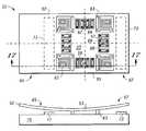
- FIG. 9depicts a general three layer device 121 containing top 123 , middle 125 and bottom 127 layers supported on a substrate 129 .
- the middle layer 125 and top layer 123are supported several microns above the substrate 129 , and thus tends to deform along the Z axis when the device is subjected to strain along the in-plane axes of the substrate. Such strain is commonly encountered, for example, during thermal cycling.
- stress gradients in the conductive layers 123 and 125also contribute to the deformation (curvature) of these layers.
- the deformation of the top layermodifies the capacitance 131 between the top and middle layers, and hence changes the Z axis output of the device.
- Packaging stressescan be reduced by coating the transducer die with an elastomer (sometimes referred to as a “dome coat”). However, such coatings complicate the manufacturing process.
- a transducerwhich comprises an unbalanced proof mass, and which is adapted to sense acceleration in at least two, and preferably three, mutually orthogonal directions.
- the transducerpreferably contains a single proof mass that is mounted to the substrate on a suspension that is compliant in all three axes, and two or more conductive plates that are mounted on the substrate under the proof mass.
- the proof masspreferably comprises a first set of sense fingers aligned along a first axis, and a second set of sense fingers aligned along a second axis, wherein said first and second axes are orthogonal.
- Each of the sense fingers in the first and second setis typically surrounded by two parallel fingers that are fixably attached to a substrate.
- the first and second set of sense fingersare preferably disposed in an arrangement that has at least two planes of symmetry, and more preferably, at least four planes of symmetry. It is also preferred that the conductive plates are arranged with the same planes of symmetry as the first and second sets of sense fingers, that the substrate is mounted on compliant springs that are disposed in an arrangement having at least two planes of symmetry, and that the proof mass is asymmetric about the line of symmetry between the two bottom plates.
- the first and second set of sense fingers in the transducerpreferably have longitudinal axes that are parallel to a first plane, and one of said two mutually orthogonal directions is perpendicular to said first plane.
- the proof mass of the transducerhas a central portion with a plurality of sense fingers disposed therein, and opposing sides adjacent to the central portion that are of unequal mass.
- the opposing sidesare of preferably of unequal dimensions.
- the transducermay further comprise first and second capacitive plates which are disposed beneath the proof mass, and which are adapted to detect movement of the proof mass along an axis perpendicular to the first plane.
- a transducersuch as an accelerometer
- a transducerwhich comprises a proof mass having first and second sets of fingers adapted to sense acceleration along first and second mutually orthogonal axes, first and second capacitive plates adapted to sense acceleration along a third axis that is orthogonal to said first and second axes, and a plurality of anchors for said proof mass, each of said anchors being attached to said proof mass by way of a spring, and wherein the weight of the proof mass is asymmetrically supported by the anchors.
- the first and second platesare typically disposed on the same side (vertically) of the proof mass and are supported on a substrate, and are adapted to capacitively sense acceleration in a direction perpendicular to said first and second axes.
- a method for making a transducercomprising the steps of providing a substrate, depositing a first conductive layer on said substrate, patterning said first conductive layer to define first and second capacitive structures therein, depositing a sacrificial layer over said first conductive layer, depositing a second conductive layer over the sacrificial layer, and patterning the second conductive layer to define a proof mass therein such that the center of mass of the proof mass is asymmetrically disposed relative to said first and second plates.
- the first and second conductive layersmay comprise a metal, but preferably comprise polysilicon, and the first and second capacitive structures are plates.
- the proof masswhich may be asymmetrically disposed relative to said first and second plates, preferably comprises a first set of sense fingers whose longitudinal axes are parallel to a first axis, and a second set of sense fingers whose longitudinal axes are parallel to a second axis.
- the proof massalso preferably comprises a plurality of fixed fingers, such that each sense finger is disposed between a pair of fixed fingers, and a plurality of compliant structures that support the proof mass above the first and second capacitive structures.
- the transducermay be an accelerometer adapted to sense acceleration in a direction perpendicular to the substrate by measuring the capacitances between the proof mass and the first and second capacitive structures.
- the first and second sets of sense fingers, the plurality of compliant structures, and the plurality of fixed fingersare disposed in an arrangement that has at least one plane, and more preferably at least two planes, of mirror symmetry orthogonal to a major surface of the second conductive layer.
- the methodmay further comprise the steps of removing at least a portion of the sacrificial layer to obtain release of the proof mass, or depositing a metal on a surface of the proof mass such that the center of mass of the proof mass is asymmetrically disposed relative to said first and second plates.
- FIG. 1is an illustration of a prior art Z axis accelerometer
- FIG. 2is a cross-section taken along LINE 2 — 2 of FIG. 1 ;
- FIG. 3is an illustration of a prior art XY accelerometer
- FIG. 4is an illustration of a first embodiment of a 3-axis accelerometer made in accordance with the teachings herein;
- FIG. 5is a simplified cross-sectional illustration showing the unbalanced proof mass in a device of the type depicted in FIG. 4 (a more detailed cross-sectional illustration taken along LINE 17 — 17 of FIG. 4 is shown in FIG. 17 );
- FIG. 6is an illustration of a second embodiment of a 3-axis accelerometer made in accordance with the teachings herein;
- FIG. 7is an illustration of a prior art accelerometer made by a three layer process flow
- FIG. 8is a cross-section taken along LINE 8 — 8 of FIG. 7 ;
- FIG. 9is an illustration depicting the effect of packaging stress in an accelerometer made by a three layer process flow
- FIG. 10is an illustration depicting the effect of packaging stress in an accelerometer made in accordance with the teachings herein;
- FIGS. 11-17illustrate one embodiment of a method for making a transducer in accordance with the teachings herein.
- conductive materialtypically doped polysilicon
- a compact, single die transducerwhich may be, for example, an accelerometer or other sensing device, is provided which may be fabricated in a two layer process flow.
- Embodiments made from a two layer process flowmay be easier and less expensive to implement than a typical three layer process flow.
- the resulting transducerhas no contribution to package stress sensitivity from the third conductive layer.
- the transducercan be made to sense along two or more mutually orthogonal axes.
- FIGS. 4-5depict one embodiment of a transducer 51 made in accordance with the teachings herein.
- the devicecomprises a central mass 53 which is supported from a frame 55 by Y sense fingers 57 and X sense fingers 59 .
- the frameis attached to a plurality of anchors 61 by a series of springs 63 that are preferably compliant in three mutually orthogonal directions.
- the anchorsare mounted on a die or other substrate 75 (see FIG. 5 ).
- Each Y sense finger 57is surrounded by two pairs of fixed fingers 66 and 68 .
- each X sense finger 59is surrounded by two fixed fingers 62 and 64 .
- the frame 55has opposing sides 65 , 67 which are of unequal mass. In this particular embodiment, this is accomplished by constructing the frame such that the opposing sides 65 and 67 are essentially equal in thickness and width, but unequal in length. Consequently, side 65 has greater mass than side 67 , thus causing the proof mass 52 (which includes the frame 55 and the central mass 53 ) to rotate/tilt about the Y axis in response to acceleration along the Z axis. This acceleration is sensed by capacitive plates 71 and 73 which are disposed beneath the proof mass.
- the Y sense fingers 57 , the X sense fingers 59 , the fixed fingers 62 , 64 , 66 , 68 , and the springs 63are evenly spaced and are disposed on opposing sides of the central mass 53 in such a way that the arrangement of these elements has two planes of mirror symmetry.
- Such symmetryis advantageous in that it allows for the substantial cancellation of cross-axis sensitivities so that, in sensing acceleration along the X and Y axes, the device senses only the components of acceleration that occur along each of these axes.
- this symmetryhas the effect that each cross-axis sensitivity occurring at one sense finger is cancelled by an equal, but opposite, cross-axis sensitivity occurring at another sense finger.
- the transducer 81 depicted thereincomprises a central mass 83 which is supported from a frame 85 by first 87 and second 89 sets of sensing fingers. Each of the first set of sensing fingers 87 is disposed between fixed fingers 86 and 88 . Likewise, each of the second set of sensing fingers 89 is disposed between fixed fingers 82 and 84 .
- the frameis supported by a series of springs 93 that are preferably compliant in three mutually orthogonal directions. Each of the springs is attached to an anchor 91 .
- the anchors 91 and the fixed fingers 82 , 84 , 86 and 88arc mounted on a die or other substrate (not shown).
- the framehas opposing sides 95 and 97 which are of unequal mass. As with the embodiment of FIGS. 4-5 , this is accomplished by constructing the frame such that the opposing sides 95 and 97 are essentially equal in thickness and width, but unequal in length. Consequently, side 95 has greater mass than side 97 .
- the proof masstilts about the Y axis in response to acceleration along the Z axis. This acceleration is sensed by capacitive plates 101 , 103 disposed beneath the proof mass.
- the transducer of FIGS. 4-5is designed such that the arrangement of the first 67 and second 69 sets of sense fingers, the fixed fingers 62 , 64 , 66 , 68 , and the springs 63 has two planes of mirror symmetry.
- the first 87 and second 89 sets of fingers used to support the central mass 83 , the fixed fingers 82 , 84 , 86 , 88 , and the springs 93are disposed in an arrangement that has two planes of mirror symmetry. Both arrangements allow for the effective elimination of cross-axis sensitivities.
- the disposition of mass in the proof massis caused to be asymmetric by making one end of the proof mass larger than the other.
- the opposing sides 65 and 67 of FIGS. 4-5could be of the same length and width, but of differing thickness.
- the mass of one of the sidescould also be made greater than that of the other side through the selective addition of materials to it, as through selective metallization or the addition of further layers or structures to a surface thereof.
- the use of such techniques to increase the weight of a proof massare described in commonly assigned and copending application U.S. Ser. No. 10/426,148, which was filed on Apr. 29, 2003, and which is incorporated by reference herein in its entirety.
- transducer designs described abovemay have a number of advantages.
- these devicesmay be made in the same type of two layer process flow used for single axis accelerometers of the type depicted in FIGS. 1 and 2 or the dual axis accelerometers of the type depicted in FIG. 3 , with all the advantages that may occur attendant thereto as have been noted above.
- the compact nature of these transducersallows them to be packaged in single small packages (similar to those used for single-axis accelerometers) with an appropriate ASIC (application specific integrated circuitry).
- ASICapplication specific integrated circuitry
- These transducersmay be less complex than existing three-axis transducers, with some embodiments requiring only one proof mass and one movable element bond pad, since all three sense axes use the same intermediate layer.
- each transducerhas its own proof mass and is supplied with its own movable element bond pad.
- the transducers disclosed hereinare inherently less expensive to manufacture than three-axis devices fashioned out of individual transducers, since these transducers may be fabricated as unitary packaged devices whose fabrication costs are about the same as that for a single axis transducer.
- the cost of fabricating a three-axis device fashioned out of individual transducersis approximately three times as much.
- the designs described hereinmay also be resistant to polysilicon stress gradients and to package stress. This fact can be appreciated with reference to FIG. 10 .
- the transducer 141 depicted thereincontains a first conductive layer in the form of first 147 and second 149 sense plates, a second conductive layer 145 , and a substrate 151 .
- the second conductive layerforms a first capacitance 155 with the first sense plate, and a second capacitance 153 with the second sense plate.
- Package stresscauses in-plane strain (stretching) of the substrate 151 , which can cause the second layer of polysilicon to move vertically, thereby increasing the gap between the second layer of polysilicon and each of the first 147 and second 149 sense plates.
- first 147 and second 149 sense platesare located symmetrically with respect to the anchor locations for the second layer 145 , there is also no change in the output signal as a result of the curvature arising from stress gradients in the second conductive layer 145 .
- transducers described hereincan be achieved through a number of different fabrication routes.
- One such routeis depicted in FIGS. 11-17 .
- a substrate 75is provided, which typically comprises silicon.
- a first conductive layer 70 of a first conductive materialis deposited on a major surface of the substrate.
- the surface to which this layer is to be appliedmay be coated with one or more layers of a dielectric material.
- the first conductive layer 70preferably comprises polysilicon (which may be suitably doped in some applications), but may also comprise other semiconductor materials or various metals.
- the first conductive layer 70is deposited, it is then masked, patterned and etched (not shown) to define capacitive plates 71 and 73 , as shown in FIG. 12.
- a sacrificial layer 72is then deposited over the capacitive plates as shown in FIG. 13 .
- the sacrificial layeris preferably phosphorosilicate glass (PSG), but may also comprise other suitable sacrificial materials as are known to the art.
- a series of contact openings 74 , 76arc then formed in the sacrificial layer to define, respectively, the anchors 61 for the spring suspension system and the fixed fingers 62 , 64 (see FIG. 4 ).
- the sacrificial layeris PSG, this may be accomplished by a suitable oxide etch that exhibits etch stop behavior at the substrate 75 .
- a second conductive material 52is deposited in the openings and overlying the sacrificial layer 72 , as shown in FIG. 15 .
- the second conductive materialpreferably comprises polysilicon (which may be suitably doped according to the application), but may also comprise various metals.
- the second conductive materialis the same, or similar to, the first conductive material of layer 70 (see FIG. 11 ).
- the first and second conductive materialsare both polysilicon.
- the second conductive material 52may be deposited through chemical vapor deposition (CVD) or by other suitable means as are known to the art.
- the second conductive layeris then masked, patterned and etched (not shown) to define the various elements of the proof mass as are shown in FIG. 16 .
- theseinclude the spring anchor 61 , the fixed fingers 62 and 64 , the sense fingers 59 , and the springs 63 .
- Release of the structureis then achieved through the use of a suitable etchant to result in the device depicted in FIG. 17 , which is a cross-section taken along LINE 17 — 17 of FIG. 4 .
- the etchantis preferably aqueous HF.
- the sacrificial layerpreferably comprises PSG and the second conductive material overlying it preferably comprises polysilicon.
- the use of these materialsis advantageous in that aqueous HF, which can be used to achieve release of the structure, is highly selective to polysilicon.
- the contacts 74 and 76which define the anchors for the springs and fixed fingers is overlaid with polysilicon, and if aqueous HF is used to release the structure, the perimeters of these anchors will be well defined and will be relatively independent of release etch process parameters such as etch time and HF concentration.
- the transducerwhich may be fabricated as a planar structure in a two layer polysilicon process flow, is thus easier to fabricate than those build in a three layer process.
Landscapes
- Physics & Mathematics (AREA)
- General Physics & Mathematics (AREA)
- Pressure Sensors (AREA)
Abstract
Description
Claims (46)
Priority Applications (7)
| Application Number | Priority Date | Filing Date | Title |
|---|---|---|---|
| US10/615,328US6845670B1 (en) | 2003-07-08 | 2003-07-08 | Single proof mass, 3 axis MEMS transducer |
| PCT/US2004/021927WO2005017536A1 (en) | 2003-07-08 | 2004-07-06 | Single proof mass, 3 axis mems transducer |
| EP04777789AEP1646878A1 (en) | 2003-07-08 | 2004-07-06 | Single proof mass, 3 axis mems transducer |
| KR1020067000408AKR101145999B1 (en) | 2003-07-08 | 2004-07-06 | Tranceducer and method for making a transducer |
| CNB2004800192805ACN100437118C (en) | 2003-07-08 | 2004-07-06 | Single proof mass, 3 axis MEMS transducer |
| JP2006518908AJP4787746B2 (en) | 2003-07-08 | 2004-07-06 | Method for manufacturing transducer |
| US11/009,109US6936492B2 (en) | 2003-07-08 | 2004-12-10 | Single proof mass, 3 axis MEMS transducer |
Applications Claiming Priority (1)
| Application Number | Priority Date | Filing Date | Title |
|---|---|---|---|
| US10/615,328US6845670B1 (en) | 2003-07-08 | 2003-07-08 | Single proof mass, 3 axis MEMS transducer |
Related Child Applications (1)
| Application Number | Title | Priority Date | Filing Date |
|---|---|---|---|
| US11/009,109DivisionUS6936492B2 (en) | 2003-07-08 | 2004-12-10 | Single proof mass, 3 axis MEMS transducer |
Publications (2)
| Publication Number | Publication Date |
|---|---|
| US20050005698A1 US20050005698A1 (en) | 2005-01-13 |
| US6845670B1true US6845670B1 (en) | 2005-01-25 |
Family
ID=33564535
Family Applications (2)
| Application Number | Title | Priority Date | Filing Date |
|---|---|---|---|
| US10/615,328Expired - LifetimeUS6845670B1 (en) | 2003-07-08 | 2003-07-08 | Single proof mass, 3 axis MEMS transducer |
| US11/009,109Expired - Fee RelatedUS6936492B2 (en) | 2003-07-08 | 2004-12-10 | Single proof mass, 3 axis MEMS transducer |
Family Applications After (1)
| Application Number | Title | Priority Date | Filing Date |
|---|---|---|---|
| US11/009,109Expired - Fee RelatedUS6936492B2 (en) | 2003-07-08 | 2004-12-10 | Single proof mass, 3 axis MEMS transducer |
Country Status (6)
| Country | Link |
|---|---|
| US (2) | US6845670B1 (en) |
| EP (1) | EP1646878A1 (en) |
| JP (1) | JP4787746B2 (en) |
| KR (1) | KR101145999B1 (en) |
| CN (1) | CN100437118C (en) |
| WO (1) | WO2005017536A1 (en) |
Cited By (67)
| Publication number | Priority date | Publication date | Assignee | Title |
|---|---|---|---|---|
| US20050173233A1 (en)* | 2002-08-02 | 2005-08-11 | Robert Bosch Gmbh | Micromechanical switch |
| US20050200938A1 (en)* | 2004-03-09 | 2005-09-15 | Greywall Dennis S. | MEMS device for an adaptive optics mirror |
| US20060075816A1 (en)* | 2002-12-10 | 2006-04-13 | Koninklijke Philips Electronics, N.V. | Activity monitoring |
| US7038150B1 (en)* | 2004-07-06 | 2006-05-02 | Sandia Corporation | Micro environmental sensing device |
| US20060277997A1 (en)* | 2005-06-14 | 2006-12-14 | Innovative Micro Technology | MEMS teeter-totter apparatus with curved beam and method of manufacture |
| US20070034007A1 (en)* | 2005-08-12 | 2007-02-15 | Cenk Acar | Multi-axis micromachined accelerometer |
| US7180019B1 (en)* | 2006-06-26 | 2007-02-20 | Temic Automotive Of North America, Inc. | Capacitive accelerometer or acceleration switch |
| US20070059857A1 (en)* | 2003-08-14 | 2007-03-15 | Kathirgamasundaram Sooriakumar | Three-axis accelerometer |
| US20070113653A1 (en)* | 2005-11-21 | 2007-05-24 | Nasiri Steven S | Multiple axis accelerometer |
| US20070214891A1 (en)* | 2006-03-14 | 2007-09-20 | Commissariat A L'energie Atomique | Triaxial membrane accelerometer |
| US20070220973A1 (en)* | 2005-08-12 | 2007-09-27 | Cenk Acar | Multi-axis micromachined accelerometer and rate sensor |
| US20080000297A1 (en)* | 2006-06-30 | 2008-01-03 | Koury Daniel N | MEMS suspension and anchoring design |
| US20080016964A1 (en)* | 2006-07-19 | 2008-01-24 | Koury Daniel N | MEMS device and method of reducing stiction in a MEMS device |
| WO2007133824A3 (en)* | 2006-01-31 | 2008-01-24 | Good Samaritan Hospital | Muscle stimulation method and system to improve walking |
| US20080087085A1 (en)* | 2006-10-11 | 2008-04-17 | Freescale Semiconductor, Inc. | Sensor having free fall self-test capability and method therefor |
| US20080142914A1 (en)* | 2006-12-18 | 2008-06-19 | Akustica, Inc. | Proof-mass with supporting structure on integrated circuit-MEMS platform and method of fabricating the same |
| US20080173091A1 (en)* | 2007-01-18 | 2008-07-24 | Freescale Semiconductor, Inc. | Differential capacitive sensor and method of making same |
| CN100458466C (en)* | 2005-07-05 | 2009-02-04 | 威海双丰物探设备股份有限公司 | MEMS acceleration earthquake sensor |
| WO2009048621A1 (en)* | 2007-10-11 | 2009-04-16 | Georgia Tech Research Corporation | Bulk acoustic wave accelerometers |
| US20090126486A1 (en)* | 2007-11-20 | 2009-05-21 | Baker Hughes Incorporated | Orientation independent gravity sensor |
| US20090165558A1 (en)* | 2007-12-28 | 2009-07-02 | Schultz Peter S | Caddie-corner single proof mass xyz mems transducer |
| US20090183570A1 (en)* | 2008-01-18 | 2009-07-23 | Custom Sensors & Technologies, Inc. | Micromachined cross-differential dual-axis accelerometer |
| US20090241670A1 (en)* | 2008-03-28 | 2009-10-01 | Oki Semiconductor Co., Ltd. | Semiconductor acceleration sensor |
| US20090282916A1 (en)* | 2008-05-16 | 2009-11-19 | Rosemount Aerospace Inc. | System and Method for Providing High-Range Capability with Closed-Loop Inertial Sensors |
| US20090297146A1 (en)* | 2008-05-30 | 2009-12-03 | Pessoa Lucio F C | Multiple core system |
| US20090295415A1 (en)* | 2008-05-30 | 2009-12-03 | Pessoa Lucio F C | Testing of multiple integrated circuits |
| US20100024554A1 (en)* | 2008-07-30 | 2010-02-04 | Johannes Classen | Triaxial acceleration sensor |
| US20100043549A1 (en)* | 2008-08-19 | 2010-02-25 | Johannes Classen | Triaxial acceleration sensor |
| US20100058864A1 (en)* | 2008-09-05 | 2010-03-11 | Industrial Technology Research Institute | Multi-axis capacitive accelerometer |
| US20100122579A1 (en)* | 2008-11-18 | 2010-05-20 | Industrial Technology Research Institute | Multi-axis capacitive accelerometer |
| US7767484B2 (en) | 2006-05-31 | 2010-08-03 | Georgia Tech Research Corporation | Method for sealing and backside releasing of microelectromechanical systems |
| US20100212423A1 (en)* | 2007-10-05 | 2010-08-26 | Dirk Rehle | Acceleration sensor |
| US20100242600A1 (en)* | 2009-03-24 | 2010-09-30 | Freescale Semiconductor, Inc. | Vertically integrated mems acceleration transducer |
| US20100242602A1 (en)* | 2009-03-31 | 2010-09-30 | Ming-Ching Wu | Process for fabricating a capacitance type tri-axial accelerometer |
| US20100313660A1 (en)* | 2009-06-15 | 2010-12-16 | Rohm Co., Ltd. | Mems device and method of fabricating the mems device |
| US20110023606A1 (en)* | 2008-04-03 | 2011-02-03 | Continental Teves Ag & Co.Ohg | Micromechanical acceleration sensor |
| US20110030475A1 (en)* | 2009-08-07 | 2011-02-10 | Heiko Stahl | Sensor element and method for operating a sensor element |
| US20110056295A1 (en)* | 2009-09-04 | 2011-03-10 | Johannes Classen | Micromechanical system |
| US20110162453A1 (en)* | 2010-01-05 | 2011-07-07 | PixArt Imaging Incorporation, R.O.C. | Mass for use in a micro-electro-mechanical-system sensor and 3-dimensional micro-electro-mechanical-system sensor using same |
| US8020443B2 (en) | 2008-10-30 | 2011-09-20 | Freescale Semiconductor, Inc. | Transducer with decoupled sensing in mutually orthogonal directions |
| US20110265568A1 (en)* | 2010-04-30 | 2011-11-03 | Qualcomm Mems Technologies, Inc. | Stacked lateral overlap transducer (slot) based three-axis accelerometer |
| US20120000287A1 (en)* | 2010-06-15 | 2012-01-05 | Stmicroelectronics S.R.L. | Microelectromechanical three-axis capacitive accelerometer |
| US8117919B2 (en) | 2008-11-13 | 2012-02-21 | PixArt Imaging Incorporation, R.O.C. | Micro-electro-mechanical system device |
| US20120125104A1 (en)* | 2010-11-24 | 2012-05-24 | Invensense, Inc. | Anchor-tilt cancelling accelerometer |
| US8372677B2 (en) | 2006-05-10 | 2013-02-12 | Qualtre, Inc. | Three-axis accelerometers and fabrication methods |
| US20130042686A1 (en)* | 2011-08-17 | 2013-02-21 | Sitronix Technology Corp. | Inertia sensing apparatus |
| US20130104654A1 (en)* | 2011-10-27 | 2013-05-02 | Robert Bosch Gmbh | Micromechanical component and method for manufacturing a micromechanical component |
| US20140024162A1 (en)* | 2010-08-19 | 2014-01-23 | MCube Inc. | Anchor design and method for mems transducer apparatuses |
| US9010185B2 (en) | 2011-12-02 | 2015-04-21 | PixArt Imaging Incorporation, R.O.C. | Three-dimensional micro-electro-mechanical-system sensor |
| US20150247879A1 (en)* | 2014-03-03 | 2015-09-03 | Infineon Technologies Ag | Acceleration sensor |
| US20150268269A1 (en)* | 2014-03-20 | 2015-09-24 | Freescale Semiconductor, Inc. | Sensor with combined sense elements for multiple axis sensing |
| US9360496B2 (en) | 2014-10-03 | 2016-06-07 | Freescale Semiconductor, Inc. | Three-axis microelectromechanical systems device with single proof mass |
| US20170023608A1 (en)* | 2015-07-21 | 2017-01-26 | Freescale Semiconductor, Inc. | Multi-axis inertial sensor with dual mass and integrated damping structure |
| US10207916B2 (en) | 2014-05-28 | 2019-02-19 | 3M Innovative Properties Company | MEMS devices on flexible substrate |
| US10352960B1 (en)* | 2015-10-30 | 2019-07-16 | Garmin International, Inc. | Free mass MEMS accelerometer |
| US10436812B2 (en) | 2015-03-20 | 2019-10-08 | Nxp Usa, Inc. | Micro-electro-mechanical acceleration sensor device |
| US20200174035A1 (en)* | 2016-03-31 | 2020-06-04 | Stmicroelectronics S.R.L. | Mems accelerometric sensor having high accuracy and low sensitivity to temperature and aging |
| US10712359B2 (en) | 2018-05-01 | 2020-07-14 | Nxp Usa, Inc. | Flexure with enhanced torsional stiffness and MEMS device incorporating same |
| US10732196B2 (en) | 2017-11-30 | 2020-08-04 | Invensense, Inc. | Asymmetric out-of-plane accelerometer |
| US10732198B2 (en) | 2017-08-09 | 2020-08-04 | Analog Devices, Inc. | Integrated linear and angular MEMS accelerometers |
| US10794701B2 (en) | 2018-05-01 | 2020-10-06 | Nxp Usa, Inc. | Inertial sensor with single proof mass and multiple sense axis capability |
| US10816569B2 (en) | 2018-09-07 | 2020-10-27 | Analog Devices, Inc. | Z axis accelerometer using variable vertical gaps |
| US11099207B2 (en) | 2018-10-25 | 2021-08-24 | Analog Devices, Inc. | Low-noise multi-axis accelerometers and related methods |
| US11255873B2 (en) | 2018-09-12 | 2022-02-22 | Analog Devices, Inc. | Increased sensitivity z-axis accelerometer |
| US11467181B2 (en)* | 2019-09-11 | 2022-10-11 | Murata Manufacturing Co., Ltd. | Low-noise multi-axis MEMS accelerometer |
| US11733263B2 (en) | 2018-09-21 | 2023-08-22 | Analog Devices, Inc. | 3-axis accelerometer |
| US12153065B2 (en) | 2016-01-07 | 2024-11-26 | Analog Devices, Inc. | 3-axis angular accelerometer |
Families Citing this family (81)
| Publication number | Priority date | Publication date | Assignee | Title |
|---|---|---|---|---|
| US20060192353A1 (en)* | 2005-02-08 | 2006-08-31 | Schubert Peter J | Method of producing a rollover arming signal based on off-axis acceleration |
| FI121539B (en)* | 2005-06-03 | 2010-12-31 | Valtion Teknillinen | A process for the production of micromechanical components, and a silicon micromechanical structure prepared by such a process and its use |
| US7337671B2 (en) | 2005-06-03 | 2008-03-04 | Georgia Tech Research Corp. | Capacitive microaccelerometers and fabrication methods |
| US7371982B2 (en)* | 2005-07-29 | 2008-05-13 | Lucent Technologies Inc. | MEMS safety and arming devices having launch and rotation interlocks and method of manufacturing the same |
| ITTO20050628A1 (en)* | 2005-09-15 | 2007-03-16 | St Microelectronics Srl | IMAGE STABILIZER DEVICE, IN PARTICULAR FOR THE ACQUISITION BY MEANS OF A DIGITAL IMAGE SENSOR |
| US20070159456A1 (en)* | 2006-01-10 | 2007-07-12 | Unkrich Mark A | Navigation system |
| JP4605087B2 (en)* | 2006-04-28 | 2011-01-05 | パナソニック電工株式会社 | Capacitive sensor |
| JP2007298405A (en)* | 2006-04-28 | 2007-11-15 | Matsushita Electric Works Ltd | Electrostatic capacity type sensor |
| US8176782B2 (en)* | 2006-04-28 | 2012-05-15 | Panasonic Electric Works Co., Ltd. | Capacitive sensor |
| JP4600344B2 (en)* | 2006-04-28 | 2010-12-15 | パナソニック電工株式会社 | Capacitive sensor |
| US7767483B1 (en)* | 2006-07-25 | 2010-08-03 | The United States Of America As Represented By The Secretary Of The Navy | Dual-suspension system for MEMS-based devices and method for fabricating same |
| DE102006048381A1 (en)* | 2006-10-12 | 2008-04-17 | Fraunhofer-Gesellschaft zur Förderung der angewandten Forschung e.V. | Sensor for detecting accelerations |
| US7851876B2 (en)* | 2006-10-20 | 2010-12-14 | Hewlett-Packard Development Company, L.P. | Micro electro mechanical system |
| TWI335903B (en)* | 2007-10-05 | 2011-01-11 | Pixart Imaging Inc | Out-of-plane sensing device |
| TWI398887B (en) | 2007-10-23 | 2013-06-11 | Pixart Imaging Inc | Method for manufacturing variable parallel capacitor plate |
| US8079262B2 (en)* | 2007-10-26 | 2011-12-20 | Rosemount Aerospace Inc. | Pendulous accelerometer with balanced gas damping |
| DE102008001442A1 (en)* | 2008-04-29 | 2009-11-05 | Robert Bosch Gmbh | Micromechanical component and method for operating a micromechanical component |
| CN102538834B (en)* | 2008-05-27 | 2015-01-14 | 原相科技股份有限公司 | Coplanar sensor and manufacturing method thereof |
| US8096182B2 (en)* | 2008-05-29 | 2012-01-17 | Freescale Semiconductor, Inc. | Capacitive sensor with stress relief that compensates for package stress |
| US8056415B2 (en)* | 2008-05-30 | 2011-11-15 | Freescale Semiconductor, Inc. | Semiconductor device with reduced sensitivity to package stress |
| US8371167B2 (en)* | 2008-07-29 | 2013-02-12 | Pixart Imaging Inc. | In-plane sensor, out-of-plane sensor, and method for making same |
| JP5103326B2 (en) | 2008-08-20 | 2012-12-19 | 株式会社オーディオテクニカ | Cooked rice molding method |
| DE102009002701B4 (en)* | 2009-04-28 | 2018-01-18 | Hanking Electronics, Ltd. | Micromechanical sensor |
| JP5089807B2 (en)* | 2009-06-03 | 2012-12-05 | アルプス電気株式会社 | Physical quantity sensor |
| EP2439542B1 (en)* | 2009-06-03 | 2014-01-15 | Alps Electric Co., Ltd. | Physical quantity sensor |
| JP2011022018A (en) | 2009-07-16 | 2011-02-03 | Mitsubishi Electric Corp | Capacitive acceleration sensor |
| US7736931B1 (en) | 2009-07-20 | 2010-06-15 | Rosemount Aerospace Inc. | Wafer process flow for a high performance MEMS accelerometer |
| DE102009027897B4 (en)* | 2009-07-21 | 2023-07-20 | Robert Bosch Gmbh | Micromechanical rotation rate sensor |
| EP2462408B1 (en)* | 2009-08-04 | 2020-05-13 | Fairchild Semiconductor Corporation | Micromachined inertial sensor devices |
| US8710599B2 (en)* | 2009-08-04 | 2014-04-29 | Fairchild Semiconductor Corporation | Micromachined devices and fabricating the same |
| US8138007B2 (en)* | 2009-08-26 | 2012-03-20 | Freescale Semiconductor, Inc. | MEMS device with stress isolation and method of fabrication |
| TWI398400B (en)* | 2009-11-25 | 2013-06-11 | Pixart Imaging Inc | Mass for use in a micro-electro-mechanical-system sensor and 3-dimensional micro-electro-mechanical-system sensor using same |
| US8984941B2 (en) | 2009-12-16 | 2015-03-24 | Y-Sensors Ltd. | Tethered, levitated-mass accelerometer |
| US9095072B2 (en) | 2010-09-18 | 2015-07-28 | Fairchild Semiconductor Corporation | Multi-die MEMS package |
| KR101443730B1 (en) | 2010-09-18 | 2014-09-23 | 페어차일드 세미컨덕터 코포레이션 | A microelectromechanical die, and a method for making a low-quadrature-error suspension |
| US9278845B2 (en) | 2010-09-18 | 2016-03-08 | Fairchild Semiconductor Corporation | MEMS multi-axis gyroscope Z-axis electrode structure |
| CN103221779B (en) | 2010-09-18 | 2017-05-31 | 快捷半导体公司 | The axle inertial sensor of micromechanics monoblock type six |
| CN103221778B (en) | 2010-09-18 | 2016-03-30 | 快捷半导体公司 | There is single micromechanics one chip three-axis gyroscope driven |
| WO2012037536A2 (en) | 2010-09-18 | 2012-03-22 | Fairchild Semiconductor Corporation | Packaging to reduce stress on microelectromechanical systems |
| WO2012040211A2 (en) | 2010-09-20 | 2012-03-29 | Fairchild Semiconductor Corporation | Microelectromechanical pressure sensor including reference capacitor |
| WO2012040245A2 (en) | 2010-09-20 | 2012-03-29 | Fairchild Semiconductor Corporation | Through silicon via with reduced shunt capacitance |
| US8555719B2 (en)* | 2011-01-24 | 2013-10-15 | Freescale Semiconductor, Inc. | MEMS sensor with folded torsion springs |
| JP5427199B2 (en) | 2011-03-17 | 2014-02-26 | 日立オートモティブシステムズ株式会社 | Semiconductor physical quantity detection sensor |
| CN102323449B (en)* | 2011-05-26 | 2012-11-28 | 西北工业大学 | Dual mass block-based triaxial micro accelerometer |
| DE102011076551B4 (en) | 2011-05-26 | 2024-02-22 | Robert Bosch Gmbh | Inertial sensor |
| TWI437231B (en)* | 2011-08-22 | 2014-05-11 | Richwave Technology Corp | Micro electro-mechanical system circuit capable of compensating capacitance variation and method thereof |
| WO2013105591A1 (en)* | 2012-01-11 | 2013-07-18 | アルプス電気株式会社 | Physical quantity sensor |
| US9062972B2 (en) | 2012-01-31 | 2015-06-23 | Fairchild Semiconductor Corporation | MEMS multi-axis accelerometer electrode structure |
| US8978475B2 (en) | 2012-02-01 | 2015-03-17 | Fairchild Semiconductor Corporation | MEMS proof mass with split z-axis portions |
| CN102539029B (en)* | 2012-02-29 | 2013-09-25 | 上海交通大学 | Three-dimensional fluid stress sensor based on flexible MEMS (microelectromechanical system) technology and array thereof |
| US8754694B2 (en) | 2012-04-03 | 2014-06-17 | Fairchild Semiconductor Corporation | Accurate ninety-degree phase shifter |
| US8742964B2 (en) | 2012-04-04 | 2014-06-03 | Fairchild Semiconductor Corporation | Noise reduction method with chopping for a merged MEMS accelerometer sensor |
| US9488693B2 (en) | 2012-04-04 | 2016-11-08 | Fairchild Semiconductor Corporation | Self test of MEMS accelerometer with ASICS integrated capacitors |
| EP2647952B1 (en) | 2012-04-05 | 2017-11-15 | Fairchild Semiconductor Corporation | Mems device automatic-gain control loop for mechanical amplitude drive |
| US9069006B2 (en) | 2012-04-05 | 2015-06-30 | Fairchild Semiconductor Corporation | Self test of MEMS gyroscope with ASICs integrated capacitors |
| KR102058489B1 (en) | 2012-04-05 | 2019-12-23 | 페어차일드 세미컨덕터 코포레이션 | Mems device front-end charge amplifier |
| EP2647955B8 (en) | 2012-04-05 | 2018-12-19 | Fairchild Semiconductor Corporation | MEMS device quadrature phase shift cancellation |
| US9625272B2 (en) | 2012-04-12 | 2017-04-18 | Fairchild Semiconductor Corporation | MEMS quadrature cancellation and signal demodulation |
| US9094027B2 (en) | 2012-04-12 | 2015-07-28 | Fairchild Semiconductor Corporation | Micro-electro-mechanical-system (MEMS) driver |
| CN102749157B (en)* | 2012-07-27 | 2014-02-19 | 江苏物联网研究发展中心 | Flexible multi-parameter sensor and manufacture method thereof |
| DE102013014881B4 (en) | 2012-09-12 | 2023-05-04 | Fairchild Semiconductor Corporation | Enhanced silicon via with multi-material fill |
| CN102865969B (en)* | 2012-09-28 | 2014-03-26 | 江苏物联网研究发展中心 | Testing device for temperature characteristic of pressure sensor |
| FR3000484B1 (en)* | 2012-12-27 | 2017-11-10 | Tronic's Microsystems | MICROELECTROMECHANICAL DEVICE COMPRISING A MOBILE MASS THAT IS ABLE TO MOVE OUT OF THE PLAN |
| DE102013216915A1 (en)* | 2013-08-26 | 2015-02-26 | Robert Bosch Gmbh | Micromechanical sensor and method for producing a micromechanical sensor |
| CN103513057A (en)* | 2013-10-23 | 2014-01-15 | 成都市宏山科技有限公司 | Two-dimensional micro acceleration sensor |
| CN103645342B (en)* | 2013-12-06 | 2016-08-17 | 杭州士兰微电子股份有限公司 | Multi-axis capacitive accelerometer and acceleration detection method |
| TWI580632B (en) | 2014-03-14 | 2017-05-01 | 財團法人工業技術研究院 | Micro-electromechanical apparatus utilizing folded spring for rotation element |
| US10203351B2 (en) | 2014-10-03 | 2019-02-12 | Analog Devices, Inc. | MEMS accelerometer with Z axis anchor tracking |
| US9733269B2 (en)* | 2014-11-06 | 2017-08-15 | Richtek Technology Corporation | Micro-electro-mechanical system (MEMS) device with multi-dimensional spring structure and frame |
| US11231441B2 (en) | 2015-05-15 | 2022-01-25 | Invensense, Inc. | MEMS structure for offset minimization of out-of-plane sensing accelerometers |
| US9952252B2 (en) | 2015-05-15 | 2018-04-24 | Invensense, Inc. | Offset rejection electrodes |
| US10274627B2 (en)* | 2015-10-30 | 2019-04-30 | Ion Geophysical Corporation | Ocean bottom seismic systems |
| US10184951B2 (en) | 2016-02-10 | 2019-01-22 | Globalfoundries Singapore Pte. Ltd. | Three-axis monolithic MEMS accelerometers and methods for fabricating same |
| US10203352B2 (en) | 2016-08-04 | 2019-02-12 | Analog Devices, Inc. | Anchor tracking apparatus for in-plane accelerometers and related methods |
| US10589983B2 (en) | 2016-09-07 | 2020-03-17 | The Government Of The United States Of America, As Represented By The Secretary Of The Navy | Silicon carbide microelectromechanical structure, device, and method |
| US10261105B2 (en) | 2017-02-10 | 2019-04-16 | Analog Devices, Inc. | Anchor tracking for MEMS accelerometers |
| US10697994B2 (en) | 2017-02-22 | 2020-06-30 | Semiconductor Components Industries, Llc | Accelerometer techniques to compensate package stress |
| US11204365B2 (en) | 2018-09-13 | 2021-12-21 | Ion Geophysical Corporation | Multi-axis, single mass accelerometer |
| US11029327B2 (en)* | 2018-10-31 | 2021-06-08 | Nxp Usa, Inc. | Inertial sensor with suspension spring structure surrounding anchor |
| CN110568220B (en)* | 2019-08-27 | 2021-04-30 | 华东光电集成器件研究所 | Anti-interference overload-resistant MEMS accelerometer |
| US20210385586A1 (en)* | 2020-06-04 | 2021-12-09 | Georgia Tech Research Corporation | Systems and methods having multi-axis sensitivity and translational mode shapes |
Citations (10)
| Publication number | Priority date | Publication date | Assignee | Title |
|---|---|---|---|---|
| US4736629A (en)* | 1985-12-20 | 1988-04-12 | Silicon Designs, Inc. | Micro-miniature accelerometer |
| US5487305A (en) | 1991-12-19 | 1996-01-30 | Motorola, Inc. | Three axes accelerometer |
| US5594171A (en) | 1994-10-31 | 1997-01-14 | Kabushiki Kaisha Tokai Rika Denki Seisakusho | Capacitance type acceleration sensor |
| US5806365A (en) | 1996-04-30 | 1998-09-15 | Motorola, Inc. | Acceleration sensing device on a support substrate and method of operation |
| US5939633A (en) | 1997-06-18 | 1999-08-17 | Analog Devices, Inc. | Apparatus and method for multi-axis capacitive sensing |
| US5962787A (en)* | 1995-10-24 | 1999-10-05 | Wacoh Corporation | Acceleration sensor |
| US6159761A (en)* | 1997-05-08 | 2000-12-12 | Wacoh Corporation | Method of manufacturing a force sensor having an electrode which changes resistance or electrostatic capacitance in response to force |
| US6223598B1 (en) | 1997-06-18 | 2001-05-01 | Analog Devices, Inc. | Suspension arrangement for semiconductor accelerometer |
| US6629461B2 (en)* | 2000-03-24 | 2003-10-07 | Onix Microsystems, Inc. | Biased rotatable combdrive actuator methods |
| US6705167B2 (en)* | 2000-07-10 | 2004-03-16 | Sensonor Asa | Accelerometer |
Family Cites Families (5)
| Publication number | Priority date | Publication date | Assignee | Title |
|---|---|---|---|---|
| DE4022464C2 (en)* | 1990-07-14 | 2000-12-28 | Bosch Gmbh Robert | Acceleration sensor |
| JP3308043B2 (en)* | 1993-06-08 | 2002-07-29 | 正喜 江刺 | Multi-axis acceleration detector |
| JPH07245413A (en)* | 1994-03-07 | 1995-09-19 | Fuji Electric Co Ltd | Acceleration sensor |
| DE19541388A1 (en)* | 1995-11-07 | 1997-05-15 | Telefunken Microelectron | Micromechanical acceleration sensor |
| US5644086A (en)* | 1996-10-08 | 1997-07-01 | Tokyo Gas Co., Ltd. | Preloaded linear beam vibration sensor |
- 2003
- 2003-07-08USUS10/615,328patent/US6845670B1/ennot_activeExpired - Lifetime
- 2004
- 2004-07-06WOPCT/US2004/021927patent/WO2005017536A1/enactiveApplication Filing
- 2004-07-06EPEP04777789Apatent/EP1646878A1/ennot_activeWithdrawn
- 2004-07-06KRKR1020067000408Apatent/KR101145999B1/ennot_activeExpired - Fee Related
- 2004-07-06CNCNB2004800192805Apatent/CN100437118C/ennot_activeExpired - Fee Related
- 2004-07-06JPJP2006518908Apatent/JP4787746B2/ennot_activeExpired - Fee Related
- 2004-12-10USUS11/009,109patent/US6936492B2/ennot_activeExpired - Fee Related
Patent Citations (11)
| Publication number | Priority date | Publication date | Assignee | Title |
|---|---|---|---|---|
| US4736629A (en)* | 1985-12-20 | 1988-04-12 | Silicon Designs, Inc. | Micro-miniature accelerometer |
| US5487305A (en) | 1991-12-19 | 1996-01-30 | Motorola, Inc. | Three axes accelerometer |
| US5594171A (en) | 1994-10-31 | 1997-01-14 | Kabushiki Kaisha Tokai Rika Denki Seisakusho | Capacitance type acceleration sensor |
| US5962787A (en)* | 1995-10-24 | 1999-10-05 | Wacoh Corporation | Acceleration sensor |
| US5806365A (en) | 1996-04-30 | 1998-09-15 | Motorola, Inc. | Acceleration sensing device on a support substrate and method of operation |
| US6159761A (en)* | 1997-05-08 | 2000-12-12 | Wacoh Corporation | Method of manufacturing a force sensor having an electrode which changes resistance or electrostatic capacitance in response to force |
| US5939633A (en) | 1997-06-18 | 1999-08-17 | Analog Devices, Inc. | Apparatus and method for multi-axis capacitive sensing |
| US6148670A (en) | 1997-06-18 | 2000-11-21 | Analog Devices, Inc. | Apparatus and method for multi-axis capacitive sensing |
| US6223598B1 (en) | 1997-06-18 | 2001-05-01 | Analog Devices, Inc. | Suspension arrangement for semiconductor accelerometer |
| US6629461B2 (en)* | 2000-03-24 | 2003-10-07 | Onix Microsystems, Inc. | Biased rotatable combdrive actuator methods |
| US6705167B2 (en)* | 2000-07-10 | 2004-03-16 | Sensonor Asa | Accelerometer |
Non-Patent Citations (10)
| Title |
|---|
| "Low Cost ±2 g/±10 g Dual Axis iMEMS(R) Accelerometers with Digital Output-ADXL202/ADXL210", Analog Devices, Inc. (C3037b-2, Rev. B, Apr., 1999). |
| "Low-Cost 2 g Dual-Axis Accelerometer with Duty Cycle Output-ADXL202E*", Analog Devices, Inc. (C02064-2.5-10, rev. A, 2000). |
| Arjun Selvakumar et al., "A High-Sensitivity Z-Axis Capacitive Silicon Microaccelerometer with a Torsional Suspension," Journal of Micromechanical Systems, vol. 7, No. 2, Jun. 1998, pp. 192-200.** |
| C. Byl, D. W. Howard, S. D. Collins and R. L. Smith, "Micromachined, Multi-Axis, Accelerometer with Liquid Proof Mass",Dept of Electrical & Computer Engineering University of California, Davis, California, Final Report 1998-99 for MICRO Project 98-145. |
| Gary Li and Ampere A. Tseng, "Low Stress Packaging of a Micromachined Accelerometer", IEEE Transactions on Electronics Packaging Manufacturing, vol. 24, No. 1 (Jan. 2001). |
| Giorgio Fontana, "High Performance Electrostatic Sensors and Actuators for LISA Proof Mass Control", arXiv:physics/0111006, vol. 4 (Jan. 25, 2002). |
| Harvey Weinberg, "Dual Axis, Low g, Fully Integrated Accelerometers", Analog Dialogue 33-1 (1999 Analog Devices). |
| Huikai Xie, Gary K. Fedder; "Vertical Comb-Finger Capacitive Actuation and Sensing For CMOS MEMS", Sensors and Actuators A95, 212-221 (2001). |
| J. Connelly, A. Kourepenis, T. Marinis, "Micromechanical Sensors in Tactical GN&C Applications", The Charles Stark Draper Laboratory, Inc., Published by the American Institute of Aeronautics and Astronautics, Inc. (2000). |
| Michael Kraft, "Micromachined Inertial Sensors-Recent Developments at BSAC", pp. 1-37 (University of California-Berkeley) (presentation given at the New England American Vacuum Society Meeting in Burlington, MA, Jun. 15, 1998). |
Cited By (127)
| Publication number | Priority date | Publication date | Assignee | Title |
|---|---|---|---|---|
| US7081592B2 (en)* | 2002-08-02 | 2006-07-25 | Robert Bosch Gmbh | Micromechanical switch |
| US20050173233A1 (en)* | 2002-08-02 | 2005-08-11 | Robert Bosch Gmbh | Micromechanical switch |
| US20060075816A1 (en)* | 2002-12-10 | 2006-04-13 | Koninklijke Philips Electronics, N.V. | Activity monitoring |
| US7845228B2 (en)* | 2002-12-10 | 2010-12-07 | Koninklijke Philips Electronics N.V. | Activity monitoring |
| US7361523B2 (en)* | 2003-08-14 | 2008-04-22 | Sensfab Pte Ltd | Three-axis accelerometer |
| US20070059857A1 (en)* | 2003-08-14 | 2007-03-15 | Kathirgamasundaram Sooriakumar | Three-axis accelerometer |
| US20050200938A1 (en)* | 2004-03-09 | 2005-09-15 | Greywall Dennis S. | MEMS device for an adaptive optics mirror |
| US7099063B2 (en)* | 2004-03-09 | 2006-08-29 | Lucent Technologies Inc. | MEMS device for an adaptive optics mirror |
| US7038150B1 (en)* | 2004-07-06 | 2006-05-02 | Sandia Corporation | Micro environmental sensing device |
| US20060277997A1 (en)* | 2005-06-14 | 2006-12-14 | Innovative Micro Technology | MEMS teeter-totter apparatus with curved beam and method of manufacture |
| US7210352B2 (en)* | 2005-06-14 | 2007-05-01 | Innovative Micro Technology | MEMS teeter-totter apparatus with curved beam and method of manufacture |
| CN100458466C (en)* | 2005-07-05 | 2009-02-04 | 威海双丰物探设备股份有限公司 | MEMS acceleration earthquake sensor |
| WO2007021399A3 (en)* | 2005-08-12 | 2007-11-08 | Bei Technologies Inc | Multi-axis micromachined accelerometer |
| US20070034007A1 (en)* | 2005-08-12 | 2007-02-15 | Cenk Acar | Multi-axis micromachined accelerometer |
| US20070220973A1 (en)* | 2005-08-12 | 2007-09-27 | Cenk Acar | Multi-axis micromachined accelerometer and rate sensor |
| US20070113653A1 (en)* | 2005-11-21 | 2007-05-24 | Nasiri Steven S | Multiple axis accelerometer |
| US7258011B2 (en)* | 2005-11-21 | 2007-08-21 | Invensense Inc. | Multiple axis accelerometer |
| WO2007133824A3 (en)* | 2006-01-31 | 2008-01-24 | Good Samaritan Hospital | Muscle stimulation method and system to improve walking |
| US20070214891A1 (en)* | 2006-03-14 | 2007-09-20 | Commissariat A L'energie Atomique | Triaxial membrane accelerometer |
| US7600428B2 (en)* | 2006-03-14 | 2009-10-13 | Commissariat A L'energie Atomique | Triaxial membrane accelerometer |
| US8372677B2 (en) | 2006-05-10 | 2013-02-12 | Qualtre, Inc. | Three-axis accelerometers and fabrication methods |
| US7767484B2 (en) | 2006-05-31 | 2010-08-03 | Georgia Tech Research Corporation | Method for sealing and backside releasing of microelectromechanical systems |
| US7180019B1 (en)* | 2006-06-26 | 2007-02-20 | Temic Automotive Of North America, Inc. | Capacitive accelerometer or acceleration switch |
| US20080000297A1 (en)* | 2006-06-30 | 2008-01-03 | Koury Daniel N | MEMS suspension and anchoring design |
| US7637160B2 (en) | 2006-06-30 | 2009-12-29 | Freescale Semiconductor, Inc. | MEMS suspension and anchoring design |
| US20080016964A1 (en)* | 2006-07-19 | 2008-01-24 | Koury Daniel N | MEMS device and method of reducing stiction in a MEMS device |
| US7628072B2 (en) | 2006-07-19 | 2009-12-08 | Freescale Semiconductor, Inc. | MEMS device and method of reducing stiction in a MEMS device |
| EP2074434A4 (en)* | 2006-10-11 | 2017-01-11 | North Star Innovations Inc. | Sensor having free fall self-test capability and method therefor |
| US20080087085A1 (en)* | 2006-10-11 | 2008-04-17 | Freescale Semiconductor, Inc. | Sensor having free fall self-test capability and method therefor |
| WO2008045660A3 (en)* | 2006-10-11 | 2008-09-12 | Freescale Semiconductor Inc | Sensor having free fall self-test capability and method therefor |
| US7487661B2 (en) | 2006-10-11 | 2009-02-10 | Freescale Semiconductor, Inc. | Sensor having free fall self-test capability and method therefor |
| JP2010507074A (en)* | 2006-10-11 | 2010-03-04 | フリースケール セミコンダクター インコーポレイテッド | Sensor having free fall self-test performance and method thereof |
| US8094980B2 (en) | 2006-12-18 | 2012-01-10 | Akustica, Inc. | Proof-mass with supporting structure on integrated circuit-MEMS platform and method of fabricating the same |
| US20100147076A1 (en)* | 2006-12-18 | 2010-06-17 | Diamond Brett M | Proof-mass with supporting structure on integrated circuit-MEMS platform and method of fabricating the same |
| US20080142914A1 (en)* | 2006-12-18 | 2008-06-19 | Akustica, Inc. | Proof-mass with supporting structure on integrated circuit-MEMS platform and method of fabricating the same |
| US7640805B2 (en) | 2006-12-18 | 2010-01-05 | Akustica, Inc. | Proof-mass with supporting structure on integrated circuit-MEMS platform |
| US7610809B2 (en) | 2007-01-18 | 2009-11-03 | Freescale Semiconductor, Inc. | Differential capacitive sensor and method of making same |
| US20080173091A1 (en)* | 2007-01-18 | 2008-07-24 | Freescale Semiconductor, Inc. | Differential capacitive sensor and method of making same |
| US8516890B2 (en)* | 2007-10-05 | 2013-08-27 | Robert Bosch Gmbh | Acceleration sensor having substrate, web, and seismic mass |
| US20100212423A1 (en)* | 2007-10-05 | 2010-08-26 | Dirk Rehle | Acceleration sensor |
| US8528404B2 (en) | 2007-10-11 | 2013-09-10 | Georgia Tech Research Corporation | Bulk acoustic wave accelerometers |
| US20160258976A1 (en)* | 2007-10-11 | 2016-09-08 | Georgia Tech Research Corporation | Bulk acoustic wave accelerometers |
| US10036764B2 (en)* | 2007-10-11 | 2018-07-31 | Georgia Tech Research Corporation | Bulk acoustic wave accelerometers |
| WO2009048621A1 (en)* | 2007-10-11 | 2009-04-16 | Georgia Tech Research Corporation | Bulk acoustic wave accelerometers |
| US20090095079A1 (en)* | 2007-10-11 | 2009-04-16 | Georgia Tech Research Corporation | Bulk acoustic wave accelerometers |
| US20090126486A1 (en)* | 2007-11-20 | 2009-05-21 | Baker Hughes Incorporated | Orientation independent gravity sensor |
| WO2009088567A1 (en)* | 2007-11-20 | 2009-07-16 | Baker Hughes Incorporated | Orientation independent gravity sensor |
| US7793542B2 (en) | 2007-12-28 | 2010-09-14 | Freescale Semiconductor, Inc. | Caddie-corner single proof mass XYZ MEMS transducer |
| US20090165558A1 (en)* | 2007-12-28 | 2009-07-02 | Schultz Peter S | Caddie-corner single proof mass xyz mems transducer |
| US20090183570A1 (en)* | 2008-01-18 | 2009-07-23 | Custom Sensors & Technologies, Inc. | Micromachined cross-differential dual-axis accelerometer |
| US20090241670A1 (en)* | 2008-03-28 | 2009-10-01 | Oki Semiconductor Co., Ltd. | Semiconductor acceleration sensor |
| US8024973B2 (en)* | 2008-03-28 | 2011-09-27 | Oki Semiconductor Co., Ltd. | Semiconductor acceleration sensor |
| US8752430B2 (en)* | 2008-04-03 | 2014-06-17 | Continental Teves Ag & Co. Ohg | Micromechanical acceleration sensor |
| US20110023606A1 (en)* | 2008-04-03 | 2011-02-03 | Continental Teves Ag & Co.Ohg | Micromechanical acceleration sensor |
| US20090282916A1 (en)* | 2008-05-16 | 2009-11-19 | Rosemount Aerospace Inc. | System and Method for Providing High-Range Capability with Closed-Loop Inertial Sensors |
| US8020440B2 (en)* | 2008-05-16 | 2011-09-20 | Rosemount Aerospace Inc. | System and method for providing high-range capability with closed-loop inertial sensors |
| US8294483B2 (en) | 2008-05-30 | 2012-10-23 | Freescale Semiconductor, Inc. | Testing of multiple integrated circuits |
| US20090297146A1 (en)* | 2008-05-30 | 2009-12-03 | Pessoa Lucio F C | Multiple core system |
| US20090295415A1 (en)* | 2008-05-30 | 2009-12-03 | Pessoa Lucio F C | Testing of multiple integrated circuits |
| US8032030B2 (en) | 2008-05-30 | 2011-10-04 | Freescale Semiconductor, Inc. | Multiple core system |
| TWI464404B (en)* | 2008-07-30 | 2014-12-11 | Bosch Gmbh Robert | Dreiachsiger beschleunigungssensor |
| US20100024554A1 (en)* | 2008-07-30 | 2010-02-04 | Johannes Classen | Triaxial acceleration sensor |
| US8333113B2 (en)* | 2008-07-30 | 2012-12-18 | Robert Bosch Gmbh | Triaxial acceleration sensor |
| DE102008040855B4 (en) | 2008-07-30 | 2022-05-25 | Robert Bosch Gmbh | Triaxial accelerometer |
| US20100043549A1 (en)* | 2008-08-19 | 2010-02-25 | Johannes Classen | Triaxial acceleration sensor |
| DE102008041327B4 (en) | 2008-08-19 | 2021-12-30 | Robert Bosch Gmbh | Triaxial accelerometer |
| US8272268B2 (en)* | 2008-08-19 | 2012-09-25 | Robert Bosch Gmbh | Triaxial acceleration sensor |
| TWI464406B (en)* | 2008-08-19 | 2014-12-11 | Bosch Gmbh Robert | Dreiachsiger beschleunigungssensor |
| US8459114B2 (en)* | 2008-09-05 | 2013-06-11 | Industrial Technology Research Institute | Multi-axis capacitive accelerometer |
| US20100058864A1 (en)* | 2008-09-05 | 2010-03-11 | Industrial Technology Research Institute | Multi-axis capacitive accelerometer |
| US8020443B2 (en) | 2008-10-30 | 2011-09-20 | Freescale Semiconductor, Inc. | Transducer with decoupled sensing in mutually orthogonal directions |
| US8117919B2 (en) | 2008-11-13 | 2012-02-21 | PixArt Imaging Incorporation, R.O.C. | Micro-electro-mechanical system device |
| US8205498B2 (en) | 2008-11-18 | 2012-06-26 | Industrial Technology Research Institute | Multi-axis capacitive accelerometer |
| US20100122579A1 (en)* | 2008-11-18 | 2010-05-20 | Industrial Technology Research Institute | Multi-axis capacitive accelerometer |
| US20100242600A1 (en)* | 2009-03-24 | 2010-09-30 | Freescale Semiconductor, Inc. | Vertically integrated mems acceleration transducer |
| US8186221B2 (en)* | 2009-03-24 | 2012-05-29 | Freescale Semiconductor, Inc. | Vertically integrated MEMS acceleration transducer |
| US20100242602A1 (en)* | 2009-03-31 | 2010-09-30 | Ming-Ching Wu | Process for fabricating a capacitance type tri-axial accelerometer |
| US8664029B2 (en)* | 2009-03-31 | 2014-03-04 | Domintech Co., Ltd. | Process for fabricating a capacitance type tri-axial accelerometer |
| US20100313660A1 (en)* | 2009-06-15 | 2010-12-16 | Rohm Co., Ltd. | Mems device and method of fabricating the mems device |
| US20110030475A1 (en)* | 2009-08-07 | 2011-02-10 | Heiko Stahl | Sensor element and method for operating a sensor element |
| US8402827B2 (en)* | 2009-08-07 | 2013-03-26 | Robert Bosch Gmbh | Sensor element and method for operating a sensor element |
| US8689633B2 (en)* | 2009-09-04 | 2014-04-08 | Robert Bosch Gmbh | Micromechanical system |
| US20110056295A1 (en)* | 2009-09-04 | 2011-03-10 | Johannes Classen | Micromechanical system |
| US8424383B2 (en) | 2010-01-05 | 2013-04-23 | Pixart Imaging Incorporation | Mass for use in a micro-electro-mechanical-system sensor and 3-dimensional micro-electro-mechanical-system sensor using same |
| US20110162453A1 (en)* | 2010-01-05 | 2011-07-07 | PixArt Imaging Incorporation, R.O.C. | Mass for use in a micro-electro-mechanical-system sensor and 3-dimensional micro-electro-mechanical-system sensor using same |
| US20110265568A1 (en)* | 2010-04-30 | 2011-11-03 | Qualcomm Mems Technologies, Inc. | Stacked lateral overlap transducer (slot) based three-axis accelerometer |
| US9605965B2 (en) | 2010-04-30 | 2017-03-28 | Snaptrack, Inc. | Micromachined piezoelectric x-axis gyroscope |
| US8584522B2 (en) | 2010-04-30 | 2013-11-19 | Qualcomm Mems Technologies, Inc. | Micromachined piezoelectric x-axis gyroscope |
| US8516886B2 (en) | 2010-04-30 | 2013-08-27 | Qualcomm Mems Technologies, Inc. | Micromachined piezoelectric X-Axis gyroscope |
| US9459099B2 (en) | 2010-04-30 | 2016-10-04 | Qualcomm Mems Technologies, Inc. | Micromachined piezoelectric x-axis gyroscope |
| US9021880B2 (en) | 2010-04-30 | 2015-05-05 | Qualcomm Mems Technologies, Inc. | Micromachined piezoelectric three-axis gyroscope and stacked lateral overlap transducer (slot) based three-axis accelerometer |
| US9032796B2 (en)* | 2010-04-30 | 2015-05-19 | Qualcomm Mems Technologies, Inc. | Stacked lateral overlap transducer (SLOT) based three-axis accelerometer |
| US8516887B2 (en) | 2010-04-30 | 2013-08-27 | Qualcomm Mems Technologies, Inc. | Micromachined piezoelectric z-axis gyroscope |
| US9410805B2 (en) | 2010-04-30 | 2016-08-09 | Qualcomm Mems Technologies, Inc. | Micromachined piezoelectric z-axis gyroscope |
| US10209072B2 (en) | 2010-04-30 | 2019-02-19 | Snaptrack Inc. | Stacked lateral overlap transducer (SLOT) based three-axis accelerometer |
| US20120000287A1 (en)* | 2010-06-15 | 2012-01-05 | Stmicroelectronics S.R.L. | Microelectromechanical three-axis capacitive accelerometer |
| US8863575B2 (en)* | 2010-06-15 | 2014-10-21 | Stmicroelectronics S.R.L. | Microelectromechanical three-axis capacitive accelerometer |
| US20140024162A1 (en)* | 2010-08-19 | 2014-01-23 | MCube Inc. | Anchor design and method for mems transducer apparatuses |
| US9376312B2 (en)* | 2010-08-19 | 2016-06-28 | MCube Inc. | Method for fabricating a transducer apparatus |
| US20120125104A1 (en)* | 2010-11-24 | 2012-05-24 | Invensense, Inc. | Anchor-tilt cancelling accelerometer |
| US8839670B2 (en)* | 2010-11-24 | 2014-09-23 | Invensense, Inc. | Anchor-tilt cancelling accelerometer |
| US20130042686A1 (en)* | 2011-08-17 | 2013-02-21 | Sitronix Technology Corp. | Inertia sensing apparatus |
| US9097736B2 (en)* | 2011-10-27 | 2015-08-04 | Robert Bosch Gmbh | Micromechanical component and method for manufacturing a micromechanical component |
| US20130104654A1 (en)* | 2011-10-27 | 2013-05-02 | Robert Bosch Gmbh | Micromechanical component and method for manufacturing a micromechanical component |
| US9010185B2 (en) | 2011-12-02 | 2015-04-21 | PixArt Imaging Incorporation, R.O.C. | Three-dimensional micro-electro-mechanical-system sensor |
| US20150247879A1 (en)* | 2014-03-03 | 2015-09-03 | Infineon Technologies Ag | Acceleration sensor |
| US10648999B2 (en) | 2014-03-03 | 2020-05-12 | Infineon Technologies Ag | Method for manufacturing an acceleration sensor |
| US20150268269A1 (en)* | 2014-03-20 | 2015-09-24 | Freescale Semiconductor, Inc. | Sensor with combined sense elements for multiple axis sensing |
| US10207916B2 (en) | 2014-05-28 | 2019-02-19 | 3M Innovative Properties Company | MEMS devices on flexible substrate |
| US9360496B2 (en) | 2014-10-03 | 2016-06-07 | Freescale Semiconductor, Inc. | Three-axis microelectromechanical systems device with single proof mass |
| US10436812B2 (en) | 2015-03-20 | 2019-10-08 | Nxp Usa, Inc. | Micro-electro-mechanical acceleration sensor device |
| US20170023608A1 (en)* | 2015-07-21 | 2017-01-26 | Freescale Semiconductor, Inc. | Multi-axis inertial sensor with dual mass and integrated damping structure |
| US9720012B2 (en)* | 2015-07-21 | 2017-08-01 | Nxp Usa, Inc. | Multi-axis inertial sensor with dual mass and integrated damping structure |
| US10352960B1 (en)* | 2015-10-30 | 2019-07-16 | Garmin International, Inc. | Free mass MEMS accelerometer |
| US12153065B2 (en) | 2016-01-07 | 2024-11-26 | Analog Devices, Inc. | 3-axis angular accelerometer |
| US20200174035A1 (en)* | 2016-03-31 | 2020-06-04 | Stmicroelectronics S.R.L. | Mems accelerometric sensor having high accuracy and low sensitivity to temperature and aging |
| US11835541B2 (en)* | 2016-03-31 | 2023-12-05 | Stmicroelectronics S.R.L. | MEMS accelerometric sensor having high accuracy and low sensitivity to temperature and aging |
| US10732198B2 (en) | 2017-08-09 | 2020-08-04 | Analog Devices, Inc. | Integrated linear and angular MEMS accelerometers |
| US10732196B2 (en) | 2017-11-30 | 2020-08-04 | Invensense, Inc. | Asymmetric out-of-plane accelerometer |
| US10794701B2 (en) | 2018-05-01 | 2020-10-06 | Nxp Usa, Inc. | Inertial sensor with single proof mass and multiple sense axis capability |
| US10712359B2 (en) | 2018-05-01 | 2020-07-14 | Nxp Usa, Inc. | Flexure with enhanced torsional stiffness and MEMS device incorporating same |
| US10816569B2 (en) | 2018-09-07 | 2020-10-27 | Analog Devices, Inc. | Z axis accelerometer using variable vertical gaps |
| US11255873B2 (en) | 2018-09-12 | 2022-02-22 | Analog Devices, Inc. | Increased sensitivity z-axis accelerometer |
| US11733263B2 (en) | 2018-09-21 | 2023-08-22 | Analog Devices, Inc. | 3-axis accelerometer |
| US11099207B2 (en) | 2018-10-25 | 2021-08-24 | Analog Devices, Inc. | Low-noise multi-axis accelerometers and related methods |
| US12146893B2 (en) | 2018-10-25 | 2024-11-19 | Analog Devices, Inc. | Low-noise multi-axis accelerometers and related methods |
| US11467181B2 (en)* | 2019-09-11 | 2022-10-11 | Murata Manufacturing Co., Ltd. | Low-noise multi-axis MEMS accelerometer |
Also Published As
| Publication number | Publication date |
|---|---|
| WO2005017536A1 (en) | 2005-02-24 |
| US20050005698A1 (en) | 2005-01-13 |
| US20050097957A1 (en) | 2005-05-12 |
| CN1816747A (en) | 2006-08-09 |
| KR20060033779A (en) | 2006-04-19 |
| EP1646878A1 (en) | 2006-04-19 |
| JP2007530914A (en) | 2007-11-01 |
| JP4787746B2 (en) | 2011-10-05 |
| US6936492B2 (en) | 2005-08-30 |
| KR101145999B1 (en) | 2012-05-15 |
| CN100437118C (en) | 2008-11-26 |
Similar Documents
| Publication | Publication Date | Title |
|---|---|---|
| US6845670B1 (en) | Single proof mass, 3 axis MEMS transducer | |
| KR101301403B1 (en) | Micromechanical acceleration sensor | |
| US8056415B2 (en) | Semiconductor device with reduced sensitivity to package stress | |
| US8468888B2 (en) | MEMS sensor capable of sensing acceleration and pressure | |
| US8020443B2 (en) | Transducer with decoupled sensing in mutually orthogonal directions | |
| US7578190B2 (en) | Symmetrical differential capacitive sensor and method of making same | |
| EP1952165B1 (en) | A tri-axis accelerometer | |
| US7368312B1 (en) | MEMS sensor suite on a chip | |
| US8443670B2 (en) | 3-axis accelerometer with gap-closing capacitive electrodes | |
| US7779689B2 (en) | Multiple axis transducer with multiple sensing range capability | |
| EP2106553B1 (en) | Differential capacitive sensor and method of making same | |
| EP1738181B1 (en) | Out-of-plane compensation electrode suspension for an accelerometer | |
| US20080314147A1 (en) | Vertically integrated 3-axis mems accelerometer with electronics | |
| US20040219340A1 (en) | Method of adding mass to MEMS structures | |
| EP3151018B1 (en) | Mems sensor with reduced cross-axis sensitivity | |
| TWI616656B (en) | A mems sensor and a semiconductor package | |
| US20070034007A1 (en) | Multi-axis micromachined accelerometer | |
| JP5292600B2 (en) | Acceleration sensor | |
| EP1365211B1 (en) | Integrated gyroscope of semiconductor material with at least one sensitive axis in the sensor plane |
Legal Events
| Date | Code | Title | Description |
|---|---|---|---|
| AS | Assignment | Owner name:MOTOROLA, INC., ILLINOIS Free format text:ASSIGNMENT OF ASSIGNORS INTEREST;ASSIGNORS:MCNEIL, ANDREW C.;LI, GARY;KOURY, DANIEL N. JR.;REEL/FRAME:014295/0300;SIGNING DATES FROM 20030702 TO 20030703 | |
| AS | Assignment | Owner name:FREESCALE SEMICONDUCTOR, INC., TEXAS Free format text:ASSIGNMENT OF ASSIGNORS INTEREST;ASSIGNOR:MOTOROLA, INC;REEL/FRAME:015360/0718 Effective date:20040404 Owner name:FREESCALE SEMICONDUCTOR, INC.,TEXAS Free format text:ASSIGNMENT OF ASSIGNORS INTEREST;ASSIGNOR:MOTOROLA, INC;REEL/FRAME:015360/0718 Effective date:20040404 | |
| STCF | Information on status: patent grant | Free format text:PATENTED CASE | |
| AS | Assignment | Owner name:CITIBANK, N.A. AS COLLATERAL AGENT, NEW YORK Free format text:SECURITY AGREEMENT;ASSIGNORS:FREESCALE SEMICONDUCTOR, INC.;FREESCALE ACQUISITION CORPORATION;FREESCALE ACQUISITION HOLDINGS CORP.;AND OTHERS;REEL/FRAME:018855/0129 Effective date:20061201 Owner name:CITIBANK, N.A. AS COLLATERAL AGENT,NEW YORK Free format text:SECURITY AGREEMENT;ASSIGNORS:FREESCALE SEMICONDUCTOR, INC.;FREESCALE ACQUISITION CORPORATION;FREESCALE ACQUISITION HOLDINGS CORP.;AND OTHERS;REEL/FRAME:018855/0129 Effective date:20061201 | |
| FEPP | Fee payment procedure | Free format text:PAYOR NUMBER ASSIGNED (ORIGINAL EVENT CODE: ASPN); ENTITY STATUS OF PATENT OWNER: LARGE ENTITY | |
| FPAY | Fee payment | Year of fee payment:4 | |
| AS | Assignment | Owner name:CITIBANK, N.A., AS COLLATERAL AGENT,NEW YORK Free format text:SECURITY AGREEMENT;ASSIGNOR:FREESCALE SEMICONDUCTOR, INC.;REEL/FRAME:024397/0001 Effective date:20100413 Owner name:CITIBANK, N.A., AS COLLATERAL AGENT, NEW YORK Free format text:SECURITY AGREEMENT;ASSIGNOR:FREESCALE SEMICONDUCTOR, INC.;REEL/FRAME:024397/0001 Effective date:20100413 | |
| FPAY | Fee payment | Year of fee payment:8 | |
| AS | Assignment | Owner name:CITIBANK, N.A., AS NOTES COLLATERAL AGENT, NEW YORK Free format text:SECURITY AGREEMENT;ASSIGNOR:FREESCALE SEMICONDUCTOR, INC.;REEL/FRAME:030633/0424 Effective date:20130521 Owner name:CITIBANK, N.A., AS NOTES COLLATERAL AGENT, NEW YOR Free format text:SECURITY AGREEMENT;ASSIGNOR:FREESCALE SEMICONDUCTOR, INC.;REEL/FRAME:030633/0424 Effective date:20130521 | |
| AS | Assignment | Owner name:CITIBANK, N.A., AS NOTES COLLATERAL AGENT, NEW YORK Free format text:SECURITY AGREEMENT;ASSIGNOR:FREESCALE SEMICONDUCTOR, INC.;REEL/FRAME:031591/0266 Effective date:20131101 Owner name:CITIBANK, N.A., AS NOTES COLLATERAL AGENT, NEW YOR Free format text:SECURITY AGREEMENT;ASSIGNOR:FREESCALE SEMICONDUCTOR, INC.;REEL/FRAME:031591/0266 Effective date:20131101 | |
| AS | Assignment | Owner name:FREESCALE SEMICONDUCTOR, INC., TEXAS Free format text:PATENT RELEASE;ASSIGNOR:CITIBANK, N.A., AS COLLATERAL AGENT;REEL/FRAME:037356/0143 Effective date:20151207 Owner name:FREESCALE SEMICONDUCTOR, INC., TEXAS Free format text:PATENT RELEASE;ASSIGNOR:CITIBANK, N.A., AS COLLATERAL AGENT;REEL/FRAME:037356/0553 Effective date:20151207 Owner name:FREESCALE SEMICONDUCTOR, INC., TEXAS Free format text:PATENT RELEASE;ASSIGNOR:CITIBANK, N.A., AS COLLATERAL AGENT;REEL/FRAME:037354/0225 Effective date:20151207 | |
| AS | Assignment | Owner name:MORGAN STANLEY SENIOR FUNDING, INC., MARYLAND Free format text:ASSIGNMENT AND ASSUMPTION OF SECURITY INTEREST IN PATENTS;ASSIGNOR:CITIBANK, N.A.;REEL/FRAME:037486/0517 Effective date:20151207 | |
| AS | Assignment | Owner name:MORGAN STANLEY SENIOR FUNDING, INC., MARYLAND Free format text:ASSIGNMENT AND ASSUMPTION OF SECURITY INTEREST IN PATENTS;ASSIGNOR:CITIBANK, N.A.;REEL/FRAME:037518/0292 Effective date:20151207 | |
| AS | Assignment | Owner name:NORTH STAR INNOVATIONS INC., CALIFORNIA Free format text:ASSIGNMENT OF ASSIGNORS INTEREST;ASSIGNOR:FREESCALE SEMICONDUCTOR, INC.;REEL/FRAME:037694/0264 Effective date:20151002 | |
| FPAY | Fee payment | Year of fee payment:12 | |
| AS | Assignment | Owner name:NXP, B.V., F/K/A FREESCALE SEMICONDUCTOR, INC., NETHERLANDS Free format text:RELEASE BY SECURED PARTY;ASSIGNOR:MORGAN STANLEY SENIOR FUNDING, INC.;REEL/FRAME:040925/0001 Effective date:20160912 Owner name:NXP, B.V., F/K/A FREESCALE SEMICONDUCTOR, INC., NE Free format text:RELEASE BY SECURED PARTY;ASSIGNOR:MORGAN STANLEY SENIOR FUNDING, INC.;REEL/FRAME:040925/0001 Effective date:20160912 | |
| AS | Assignment | Owner name:NXP B.V., NETHERLANDS Free format text:RELEASE BY SECURED PARTY;ASSIGNOR:MORGAN STANLEY SENIOR FUNDING, INC.;REEL/FRAME:040928/0001 Effective date:20160622 | |
| AS | Assignment | Owner name:MORGAN STANLEY SENIOR FUNDING, INC., MARYLAND Free format text:CORRECTIVE ASSIGNMENT TO CORRECT THE REMOVE PATENTS 8108266 AND 8062324 AND REPLACE THEM WITH 6108266 AND 8060324 PREVIOUSLY RECORDED ON REEL 037518 FRAME 0292. ASSIGNOR(S) HEREBY CONFIRMS THE ASSIGNMENT AND ASSUMPTION OF SECURITY INTEREST IN PATENTS;ASSIGNOR:CITIBANK, N.A.;REEL/FRAME:041703/0536 Effective date:20151207 | |
| AS | Assignment | Owner name:SHENZHEN XINGUODU TECHNOLOGY CO., LTD., CHINA Free format text:CORRECTIVE ASSIGNMENT TO CORRECT THE TO CORRECT THE APPLICATION NO. FROM 13,883,290 TO 13,833,290 PREVIOUSLY RECORDED ON REEL 041703 FRAME 0536. ASSIGNOR(S) HEREBY CONFIRMS THE THE ASSIGNMENT AND ASSUMPTION OF SECURITYINTEREST IN PATENTS.;ASSIGNOR:MORGAN STANLEY SENIOR FUNDING, INC.;REEL/FRAME:048734/0001 Effective date:20190217 | |
| AS | Assignment | Owner name:MORGAN STANLEY SENIOR FUNDING, INC., MARYLAND Free format text:CORRECTIVE ASSIGNMENT TO CORRECT THE REMOVE APPLICATION11759915 AND REPLACE IT WITH APPLICATION 11759935 PREVIOUSLY RECORDED ON REEL 037486 FRAME 0517. ASSIGNOR(S) HEREBY CONFIRMS THE ASSIGNMENT AND ASSUMPTION OF SECURITYINTEREST IN PATENTS;ASSIGNOR:CITIBANK, N.A.;REEL/FRAME:053547/0421 Effective date:20151207 | |
| AS | Assignment | Owner name:NXP B.V., NETHERLANDS Free format text:CORRECTIVE ASSIGNMENT TO CORRECT THE REMOVEAPPLICATION 11759915 AND REPLACE IT WITH APPLICATION11759935 PREVIOUSLY RECORDED ON REEL 040928 FRAME 0001. ASSIGNOR(S) HEREBY CONFIRMS THE RELEASE OF SECURITYINTEREST;ASSIGNOR:MORGAN STANLEY SENIOR FUNDING, INC.;REEL/FRAME:052915/0001 Effective date:20160622 | |
| AS | Assignment | Owner name:NXP, B.V. F/K/A FREESCALE SEMICONDUCTOR, INC., NETHERLANDS Free format text:CORRECTIVE ASSIGNMENT TO CORRECT THE REMOVEAPPLICATION 11759915 AND REPLACE IT WITH APPLICATION11759935 PREVIOUSLY RECORDED ON REEL 040925 FRAME 0001. ASSIGNOR(S) HEREBY CONFIRMS THE RELEASE OF SECURITYINTEREST;ASSIGNOR:MORGAN STANLEY SENIOR FUNDING, INC.;REEL/FRAME:052917/0001 Effective date:20160912 | |
| AS | Assignment | Owner name:ORGANIZATION - WORLD INTELLECTUAL PROPERTY, LOUISIANA Free format text:MERGER AND CHANGE OF NAME;ASSIGNORS:UNITED STATES OF AMERICA;ORGANIZATION - WORLD INTELLECTUAL PROPERTY;REEL/FRAME:056813/0978 Effective date:19650115 |